


Owner’s Guide 0300198-03 Rev. B
COMPACT™ I/O
UNIVERSAL
ANALOG INPUT MODULE
Catalog Number: 1769sc-IF8u
Important Notes |
1. Please read all the information in this owner’s guide before installing |
|
the product. |
|
2. The information in this owner's guide applies to hardware Series A and |
|
firmware version 1.0 or later. |
|
3. This guide assumes that the reader has a full working knowledge of the |
|
relevant processor. |
|
Notice |
|
The products and services described in this owner's guide are useful in a |
|
wide variety of applications. Therefore, the user and others responsible |
|
for applying the products and services described herein are responsible |
|
for determining their acceptability for each application. While efforts |
|
have been made to provide accurate information within this owner's |
|
guide, Spectrum Controls assumes no responsibility for the accuracy, |
|
completeness, or usefulness of the information herein. |
|
Under no circumstances will Spectrum Controls be responsible or liable |
|
for any damages or losses, including indirect or consequential damages |
|
or losses, arising out of either the use of any information within this |
|
owner's guide or the use of any product or service referenced herein. |
|
No patent liability is assumed by Spectrum Controls with respect to the |
|
use of any of the information, products, circuits, programming, or |
|
services referenced herein. |
|
The information in this owner's guide is subject to change without notice. |
|
LimitedWarranty |
|
Spectrum Controls warrants that its products are free from defects in |
|
material and workmanship under normal use and service, as described in |
|
Spectrum Controls literature covering this product, for a period of 1 year. |
|
The obligations of Spectrum Controls under this warranty are limited to |
|
replacing or repairing, at its option, at its factory or facility, any product |
|
which shall, in the applicable period after shipment, be returned to the |
|
Spectrum Controls facility, transportation charges prepaid, and which |
|
after examination is determined, to the satisfaction of Spectrum Controls, |
|
to be thus defective. |
|
This warranty shall not apply to any such equipment which shall have |
|
been repaired or altered except by Spectrum Controls or which shall |
|
have been subject to misuse, neglect, or accident. In no case shall the |
|
liability of Spectrum Controls exceed the purchase price. The |
|
aforementioned provisions do not extend the original warranty period of |
|
any product which has either been repaired or replaced by Spectrum |
|
Controls. |
Table of Contents
Preface ix
Chapter 1 Module Overview 1
Chapter 2
Quick Start
for Experienced Users 9
Chapter 3
Installation and
Wiring 17
Who Should Use This |
|
Manual ..................................................................................................................... |
ix |
How to Use This Manual ........................................................................................ |
ix |
Related Documentation ........................................................................................... |
ix |
Conventions Used in |
|
This Manual ............................................................................................................. |
x |
General Description .................................................................................................. |
1 |
Input Types and Ranges .......................................................................................... |
1 |
Data Formats ............................................................................................................ |
2 |
Filter Frequencies ..................................................................................................... |
2 |
Hardware Features .................................................................................................... |
3 |
System Overview ...................................................................................................... |
4 |
Module Operation .................................................................................................... |
5 |
Module Field Calibration .......................................................................................... |
7 |
Before You Begin ...................................................................................................... |
9 |
Required Tools and |
|
Equipment ................................................................................................................. |
9 |
What You Need To Do ............................................................................................. |
9 |
Compliance to European |
|
Union Directives ..................................................................................................... |
17 |
Power Requirements ............................................................................................... |
18 |
General Considerations .......................................................................................... |
18 |
System Assembly ................................................................................................... |
20 |
Mounting ................................................................................................................ |
22 |
Replacing a Single |
|
Module within a System ......................................................................................... |
24 |
Field Wiring |
|
Connections |
|
System Wiring Guidelines ...................................................................................... |
25 |
Cold Junction |
|
Compensation ......................................................................................................... |
30 |
vi |
Compact IO™ Universal Input Module |
Chapter 4
Module Data, Status,
and Channel
Configuration 33
Chapter 5 Diagnostics and Troubleshooting 57
Appendix A 1769sc-IF8U Specifications 65
Appendix B
Two’s Complement
Binary
Numbers 69
Appendix C
Thermocouple
Descriptions 73
Module Memory Map ............................................................................................ |
33 |
Accessing Input Image File Data ........................................................................... |
34 |
Input Data File ........................................................................................................ |
34 |
Module Configuration ............................................................................................ |
36 |
Determining Effective Resolution and Range ........................................................ |
50 |
Determining Module Update Time ......................................................................... |
52 |
Safety Considerations ............................................................................................ |
57 |
Module Operation vs. Channel Operation ............................................................. |
58 |
Power-up Diagnostics ............................................................................................ |
58 |
Channel Diagnostics .............................................................................................. |
59 |
Non-critical vs. Critical Module Errors ................................................................... |
60 |
Module Error Definition Table ............................................................................... |
61 |
Error Codes ............................................................................................................. |
62 |
Module Inhibit Function ........................................................................................ |
63 |
Electrical Specifications |
|
1769sc-IF8U ............................................................................................................ |
65 |
Environmental Conditions ...................................................................................... |
68 |
Regulatory |
|
Compliance ............................................................................................................. |
68 |
Positive Decimal |
|
Values ..................................................................................................................... |
69 |
Negative Decimal Values ........................................................................................ |
70 |
International Temperature Scale of 1990 ................................................................ |
73 |
Type B Thermocouples .......................................................................................... |
73 |
Type E Thermocouples .......................................................................................... |
75 |
Type J Thermocouples ........................................................................................... |
77 |
Type K Thermocouples .......................................................................................... |
78 |
Type N Thermocouples .......................................................................................... |
80 |
Type R Thermocouples .......................................................................................... |
82 |
Type S Thermocouples .......................................................................................... |
83 |
Type T Thermocouples .......................................................................................... |
86 |
References .............................................................................................................. |
88 |
Table of Contents |
vii |
Appendix D
Using
Thermocouple
Junctions 95
Appendix E Module
Configuration Using MicroLogix 1500 and RSLogix 500 101
Appendix F Configuring Your 1769sc-IF8U Module with the Generic Profile for CompactLogix Controllers in RSLogix 5000 107
Using a Grounded Junction Thermocouple ........................................................... |
95 |
Using an Ungrounded (Isolated) Junction Thermocouple .................................... |
97 |
Using an Exposed Junction Thermocouple ........................................................... |
97 |
Module Addressing ............................................................................................. |
101 |
Configuring the 1769sc-IF8U |
|
in a MicroLogix 1500 System ................................................................................ |
103 |
Configuring I/O Modules ..................................................................................... |
111 |
Configuring a 1769sc-IF8U Universal Module .................................................... |
112 |
Declaration of Conformity .................................................................................... |
115 |
viii |
Compact IO™ Universal Input Module |
Who Should Use
This
Manual
How to Use This Manual
Related
Documentation
Preface
Read this preface to familiarize yourself with the rest of the manual. This preface covers the following topics:
·who should use this manual
·how to use this manual
·related publications
·conventions used in this manual
·Rockwell Automation support
Use this manual if you are responsible for designing, installing, programming, or troubleshooting control systems that use Allen-Bradley Compact™ I/O and/or compatible controllers, such as MicroLogix 1500 or CompactLogix.
As much as possible, we organized this manual to explain, in a task-by- task manner, how to install, configure, program, operate and troubleshoot a control system using the 1769sc-IF8u.
The table below provides a listing of publications that contain important information about MicroLogix 1500 systems.
Document Title |
Document Number |
|
|
MicroLogix™ 1500 User Manual |
1764-UM001A-US-P |
1769 Compact Discrete Input/Output Modules |
|
Product Data |
1769-2.1 |
MicroLogix™ 1500 System Overview |
1764-SO001B-EN-P |
Compact™ I/O System Overview |
1769-SO001A-EN-P |
CompactLogix User Manual |
1769-UM007B-EN-P |
Allen-Bradley Programmable Controller |
|
Grounding and Wiring Guidelines |
1770-4.1 |
If you would like a manual, you can:
·download a free electronic version from the internet at www.theautomationbookstore.com
·purchase a printed manual by:
contacting your local distributor or Rockwell Automation representative · visiting www.theautomationbookstore.com and placing your order

xCompact™ I/O Universal Input Module
·calling 1.800.963.9548 (USA/Canada) or 001.330.725.1574 (Outside USA/Canada)
Conventions Used in
This Manual
The following conventions are used throughout this manual:
·Bulleted lists (like this one) provide information not procedural steps.
·Numbered lists provide sequential steps or hierarchical information.
·Italic type is used for emphasis.
·Text in this font indicates words or phrases you should type.
General
Description
Input Types and R a n g e s
Chapter 1
Module Overview
This chapter describes the 1769-IF8u Universal Input Module and explains how the module reads current, voltage, RTD, Resistance and thermocouple/millivolt analog input data. Included is information about:
·the module’s hardware and diagnostic features
·an overview of the system and module operation
·compatibility
The universal input module supports current, voltage, RTD, resistance, thermocouple and millivolt type inputs. The module digitally converts and stores analog data from any combination mentioned above. Each input channel is individually configured via software for a specific input device, data format and filter frequency, and provides open-circuit, over-range and under-range detection and indication.
Note: There are 8 on-board jumpers to configure between voltage and current modes. In current modes the module measures the input current across a low-drift precision resistor, measures the voltage, and converts to a current reading. For any input other than direct current measurements, the jumpers must be configured for voltage mode..
The tables below list the input types and their associated ranges.
Input Type |
|
Ohm s |
|
Resistance |
|
0-150, 0-1000, 0-3000 |
|
|
|
|
|
RTD Type |
Temperature Range (*C) |
|
|
Copper 426 |
-100 to 260 |
|
|
Nickel 618 |
-100 to 260 |
|
|
Nickel 672 |
-80 to 260 |
|
|
Nickel-Iron 518 |
-200 to 200 |
|
|
Platinum385 |
-200 to 850 |
|
|
|
|
|
|
Platinum3916 |
-200 to 630 |
|
|
|
|
|
|

2 |
Compact IO™ Universal Input module |
Data Formats
Filter
Fr equencies
Therm ocouple Type |
Tem perature Range |
Type B |
300 to 1820C |
|
|
Type C |
0 to 2315C |
|
|
Type E |
-270 to 1000C |
|
|
Type J |
-210 to 1200C |
|
|
Type K |
-270 to 1370C |
|
|
Type N |
0 to 1300C |
Type R |
0 to 1768C |
Type S |
0 to 1768C |
Type T |
-270 to 400C |
Voltage Types
±50 mV
±100 mV
±10 V
0 to 10 V
0 to 5 V
1 to 5 V
Current Input Range
0 to 20mA
4mA to 20mA
The data can be configured on board each module as:
·engineering units x 1
·engineering units x 10
·scaled-for-PID
·percent of full-scale
·raw/proportional data
The module uses a digital filter that provides high frequency noise rejection for the input signals. The filter is programmable, allowing you to select from six different filter frequencies for each channel:
·10 Hz
·50 Hz
·60 Hz
·250 Hz
·500 Hz
·1000 Hz
Chapter 1: Module Overview |
3 |
H a r d w a r e Featur es
The module contains a removable terminal block. Channels are wired as differential inputs with the exception of RTD and resistance type inputs. One cold junction compensation (CJC) sensor can be added to the terminal block to enable accurate readings when using thermocouple input types. The CJC sensor compensates for offset voltages introduced into the input signal as a result of the cold-junction where the thermocouple wires are connected to the module.
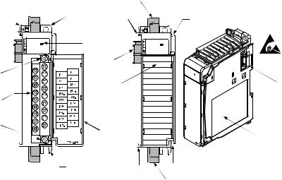
Module configuration is done via the controller’s programming software and hardware jumper settings. In addition, some controllers support configuration via the user program. In either case, the module configuration is stored in the memory of the controller. Refer to your controller’s user manual for more information. The illustration below shows the module’s hardware features.
1 |
2a |
|
OK |
|
Universal |
|
DANGER |
|
Do Not Remove RTB Under |
|
PowerUnless Area is Non- |
10a |
Hazardous |
|
|
10 |
|
10b |
|
|
Ensure Adjacent Bus |
|
Lever is Unlatched/ |
|
Latched Before/After |
|
Removing/Inserting |
|
Module |
|
2b |
|
8a |
7a |
7a |
3 |
OK |
|
Universal |
5a |
|
9 |
5b |
4 |
6 |
|
|
7b |
7b |
|
8b |
Item |
Description |
|
|
1 |
bus lever |
2a |
upper panel mounting tab |
2b |
lower panel mounting tab |
3module status LED
4module door with terminal identification label
5a |
movable bus connector (bus interface) with female pins |
5b |
stationary bus connector (bus interface) with male pins |
6 |
nameplate label |
7a |
upper tongue-and-groove slots |
7b |
lower tongue-and-groove slots |
8a |
upper DIN rail latch |
4 |
Compact IO™ Universal Input module |
8b |
lower DIN rail latch |
9write-on label for user identification tags
10removable terminal block (RTB) with finger-safe cover
10a |
RTB upper retaining screw |
10b |
RTB lower retaining screw |
11 |
CJC sensor |
S y s t e m O ve r v i e w
General Diagnostic Features
The module contains a diagnostic LED that helps you identify the source of problems that may occur during power-up or during normal channel operation. The LED indicates both status and power. Power-up and channel diagnostics are explained in Chapter 5, Diagnostics and Troubleshooting.
The modules communicate to the controller through the bus interface. The modules also receive 5 and 24V dc power through the bus interface.
System Operation
At power-up, the module performs a check of its internal circuits, memory, and basic functions. During this time, the module status LED remains off. If no faults are found during power-up diagnostics, the module status LED is turned on.
After power-up checks are complete, the module waits for valid channel configuration data. If an invalid configuration is detected, the module generates a configuration error. Once a channel is properly configured and enabled, it continuously converts the input data to a value within the range selected for that channel.
Each time a channel is read by the input module, that data value is tested by the module for an over-range, under-range, open-circuit, or “input data not valid” condition. If such a condition is detected, a unique bit is set in the channel status word. The channel status word is described in the Input Data File in chapter 4.
Using the module image table, the controller reads the two’s complement binary converted input data from the module. This typically occurs at the end of the program scan or when commanded by the control program. If the controller and the module determine that the data transfer has been made without error, the data is used in the control program.

Chapter 1: Module Overview |
5 |
M o d u l e Operation
When the module receives the input from an analog device, the module’s circuitry multiplexes the input into an A/D converter. The converter reads the signal and converts it as required for the type of input. If thermocouples are being utilized, the module continuously samples the CJC sensor and compensates for temperature changes at the terminal block cold junction, between the thermocouple wire and the input channel. See the block diagram below.
|
|
|
|
|
|
|
|
|
|
|
|
|
500V DC Isolation |
|
|
|
|
|
|
|
|
|
|
|
|
|
|||||||||||||
|
|
|
|
|
|
|
|
|
|
|
|
|
|
|
|
|
|
|
|
||||||||||||||||||||
|
|
|
|
|
|
|
|
|
|
|
|
|
|
|
|
|
|
|
|
|
|
|
|
|
|
|
Isource |
|
|
|
|
|
|
|
CJC Input |
||||
|
|
|
|
|
|
|
|
|
|
|
|
|
|
|
|
|
|
|
|
|
|
|
|
|
|
|
|
|
|
|
|
|
|||||||
|
|
|
Mercury ASIC |
|
|
|
|
|
|
|
|
|
|
|
|
|
|
|
|
|
|
|
|
|
|
|
|
|
|
|
|
|
|
|
|||||
|
|
|
|
|
|
|
|
|
|
|
|
|
|
|
|
|
|
|
|
|
|
|
|
|
|
|
|
|
|
|
|
|
|
|
|
||||
|
|
|
|
|
|
|
|
|
|
|
|
|
|
|
|
2.5 |
|
|
|
|
|
|
|
|
|
|
|
|
|
|
|
|
|
|
|||||
|
|
|
|
|
|
|
|
|
|
|
|
|
|
Isolation |
|
|
|
|
|
MHz |
|
|
|
|
|
|
|
|
|
|
|
18-pin |
|
|
|||||
|
|
|
|
|
|
|
|
|
|
|
|
|
|
|
|
|
|
|
Input |
|
|
|
|
Inputs |
|||||||||||||||
|
|
|
|
|
|
|
|
|
|
|
|
|
|
|
|
|
|
|
|
|
|
|
|
|
|
|
|
|
|
|
|
|
|
||||||
|
|
|
|
|
|
|
|
|
|
|
|
|
|
|
|
|
|
|
|
|
|
|
|
|
|
|
|
|
|
|
|
|
|
||||||
|
|
|
|
|
|
|
|
|
|
|
|
|
|
|
|
|
|
|
|
|
|
|
|
|
|
|
|
|
|
|
|
|
|
||||||
|
|
|
|
|
|
|
|
|
|
|
|
|
|
|
|
|
|
ADC |
|
|
|
|
|
|
|
|
|
|
|||||||||||
|
|
|
|
|
|
|
|
|
|
|
|
|
|
|
|
|
|
|
|
|
|
|
|
|
|
|
Block |
||||||||||||
|
|
|
|
|
|
|
|
|
|
|
|
|
|
Optical |
|
|
Sigma Delta |
|
|
|
|
|
|
Mux |
|
|
|
|
Terminal |
RTD/Ohm/V/I/TC |
|||||||||
|
|
|
|
|
|
|
|
|
|
|
|
|
|
|
|
|
|
|
|
|
|
|
|
|
|
|
|
|
|
|
|
|
|
|
|
|
|
|
|
|
|
|
|
|
|
|
|
|
|
|
|
|
|
|
|
|
|
|
|
|
|
|
|
|
|
|
|
|
|
|
|
|
|
|
|
|
|
|
|
|
|
|
|
|
|
|
|
|
|
|
|
|
|
|
|
|
|
|
|
|
|
|
|
|
|
|
|
|
|
|
|||||||||
|
|
|
80c51XA |
|
|
|
|
|
|
|
|
|
|
|
|
|
2.5V Ref |
|
|
|
|
|
|
|
|
|
|
|
|
|
|
||||||||
|
|
|
|
|
|
|
|
|
|
|
|
|
|
|
|
|
|
|
|
|
|
|
|
|
|
|
|
||||||||||||
|
|
|
processor w/ |
|
|
|
|
|
|
|
|
|
|
|
|
|
|
|
|
|
|
|
|
|
|
|
|
|
|
|
|
|
|
|
|
|
|||
LED |
|
|
flash & SRAM |
|
|
|
|
|
|
|
|
|
|
|
|
|
|
|
|
|
|
|
|
|
|
|
|
|
|
|
|
|
|
|
|
|
|||
|
|
|
|
|
|
|
|
|
|
|
|
|
|
|
|
|
|
|
|
|
|
|
|
|
|
|
|
Offset Calibration |
|
|
|
|
|
|
|
||||
|
|
|
|
|
|
|
|
|
|
|
|
|
|
|
|
|
|
|
|
|
|
|
|
|
|
|
|
|
|
|
|
|
|
|
|||||
|
|
|
|
|
|
|
|
|
|
|
|
|
|
|
|
|
|
|
|
|
|
|
|
|
|
|
|
|
|
|
|
|
|
||||||
|
|
|
|
5VD |
|
|
|
3.3VD |
|
|
|
|
|
|
|
|
|
|
|
|
|
|
|
|
|
|
|
|
|
|
|
|
|||||||
|
|
5V |
|
|
|
|
|
|
|
|
|
|
|
|
|
|
|
|
|
|
|
|
|
|
|
|
|
|
|
|
|
|
|
|
|
|
|
|
|
|
|
|
|
3.3V |
|
|
|
|
|
|
|
|
|
|
|
|
|
|
|
|
|
|
|
|
|
|
|
|
|
|
|
|
|
|
|
||||
|
|
|
|
|
|
|
|
|
|
|
|
|
|
|
|
|
|
|
|
|
|
|
|
|
|
|
|
|
|
|
|
|
|
|
|||||
|
|
|
|
|
|
|
Reg |
|
|
|
|
Isolated |
|
|
|
|
|
|
+/-15V |
|
|
|
|
|
|
5VI |
|
|
|||||||||||
|
|
24V |
|
|
|
|
|
|
|
|
|
|
|
|
|
|
|
|
|
|
|
|
|
|
|
|
|
|
|
|
|
|
|||||||
|
|
|
|
|
|
|
|
Power Supply |
|
|
|
|
|
|
|
|
|
|
|
|
|
5V Reg |
|
|
|
|
|
|
|
|
|||||||||
|
|
|
|
|
|
|
|
|
|
|
|
|
24V to +/-15V |
|
|
|
|
|
|
|
|
|
|
|
|
|
|
|
|
|
|
|
|
|
|||||
|
|
|
|
|
|
|
|
|
|
|
|
|
|
|
|
|
|
|
|
|
|
|
|
|
|
|
|
|
|
|
|
|
|
|
|
|
|||
|
|
|
|
|
|
|
|
|
|
|
|
|
|
|
|
|
|
|
|
|
|
|
|
|
|
|
|
|
|
|
|
|
|
|
|
|
|
|
|
The module is designed to support up to 4 channels of RTD or resistance and up to 8 channels of voltage, current, or thermocouple, but not concurrently. For every channel of RTD or resistance the module consumes 2 possible channels of voltage, current or thermocouple inputs. This is due to terminal block limitations in a single board module. There are five possible channel configuration combinations under this design architecture. See table below.
Configuration Choices for the 1769sc-IF8u
8 channels Voltage/Current/Thermocouple + 0 channels RTD/Resistance
6 channels Voltage/Current/Thermocouple + 1 channels RTD/Resistance
4 channels Voltage/Current/Thermocouple + 2 channels RTD/Resistance
2 channels Voltage/Current/Thermocouple + 3 channels RTD/Resistance
0 channels Voltage/Current/Thermocouple + 4 channels RTD/Resistance
6 |
Compact IO™ Universal Input module |
Thermocouple and RTD measurements are linearized using the specifications listed in the table below.
Input Type |
Specification |
100? Pt 385 |
IEC-751, 1983 |
200Ω Pt 385 |
IEC-751, 1983 |
500Ω Pt 385 |
IEC-751, 1983 |
1000Ω Pt 385 |
IEC-751, 1983 |
100Ω Pt 3916 |
JIS C 1604, 1989 |
200Ω Pt 3916 |
IEC-751, 1983 |
500Ω Pt 3916 |
IEC-751, 1983 |
1000Ω Pt 3916 |
IEC-751, 1983 |
10Ω Cu 426 |
SAMA RC21-4-1966 |
120Ω Ni 618 |
DIN 43760 Sept. 1987 |
120Ω Ni 672 |
MINCO Application Aid #18, Date 5/90 |
604Ω Ni Fe 518 |
MINCO Application Aid #18, Date 5/90 |
J |
NIST ITS 90 |
K |
NIST ITS 90 |
T |
NIST ITS 90 |
E |
NIST ITS 90 |
R |
NIST ITS 90 |
S |
NIST ITS 90 |
B |
NIST ITS 90 |
N |
NIST ITS 90 |
C |
From the Annual Book of Standards, American Society for Testing Materials |
Thermocouple measurements utilize a single cold junction compensation sensor placed in the center of the terminal block. Thermocouple support includes types J, K, T, E, R, S, B, N, C with a range to 100 mV. In thermocouple mode the 1769sc-IF8u will measure thermocouple and CJC sensor voltages and convert the results to a linearized temperature reading. RTD support includes types Pt 385, Pt 3916, Ni 618, Ni 672, and Cu 426. In RTD and resistance modes the module will inject a constant current through the RTD or resistor, measure the voltage across the resistance, and convert to a linearized temperature or resistance reading. RTD and resistance input types support 2, 3, or 4-wire resistance measurements.
When configured for current or voltage type inputs, the module converts the analog values directly into digital counts.
Chapter 1: Module Overview |
7 |
Module Field
Calibration
The module provides autocalibration, which compensates for offset and gain drift of the A/D converter caused by a temperature change within the module. An internal, high-precision, low drift voltage and system ground reference is used for this purpose. The input module performs autocalibration when a channel is initially enabled. In addition, you can program the module to perform a calibration cycle once every 5 minutes. See Selecting Enable/Disable Cyclic Calibration (Configuration Word 0, Bit 14) in chapter 4 for information on configuring the module to perform periodic autocalibration.
8 |
Compact IO™ Universal Input module |
|
Chapter 2 |
|
Quick Start |
|
for Experienced Users |
Before You Begin |
This chapter can help you to get started using the 1769sc-IF8u Universal |
|
input module. We base the procedures here on the assumption that you |
|
have an understanding of Allen-Bradley controllers. You should |
|
understand electronic process control and be able to interpret the ladder |
|
logic instructions required to generate the electronic signals that control |
|
your application. |
|
Because it is a start-up guide for experienced users, this chapter does not |
|
contain detailed explanations about the procedures listed. It does, |
|
however, reference other chapters in this book where you can get more |
|
information about applying the procedures described in each step. |
|
If you have any questions or are unfamiliar with the terms used or |
|
concepts presented in the procedural steps, always read the referenced |
|
chapters and other recommended documentation before trying to apply |
|
the information. |
Required Tools and |
|
Equipment |
Have the following tools and equipment ready: |
|
· medium blade or cross-head screwdriver |
|
· thermocouple or millivolt analog input device |
|
· shielded, twisted-pair cable for wiring (Belden™ 8761 or equivalent for |
|
millivolt and current inputs, Belden™ 9501, 9533 for RTD or shielded |
|
thermocouple extension wire for thermocouple inputs) |
|
· controller (for example, a MicroLogix™ 1500 or CompactLogix™ |
|
controller) |
|
· programming device and software (for example, RSLogix 500™ or |
|
RSLogix 5000™) |
What You Need To Do |
This chapter covers: |
|
1. Ensuring that your power supply is adequate |
|
2. Attaching and locking the module |

10Compact IO™ Universal Input module
3.Wiring the module
4.Configuring the module
5.Going through the startup procedure
6.Monitoring module operation
Step 1: Ensure that your 1769 system |
|
power supply(1) has sufficient current |
Reference |
output to support your system configuration. |
|
|
Chapter 3 |
|
(Installation and Wiring) |
The modules maximum current draw is shown below
5V dc |
24V dc |
|
|
150 mA |
45 mA |
NOTE The module cannot be located more than 8 modules away from the system power supply.
(1) The system power supply could be a 1769-PA2, -PB2, -PA4, -PB4, or the internal supply of the MicroLogix 1500 packaged controller.
Step 2: Attach and lock the module. |
Reference |
Chapter 3
(Installation and Wiring)
NOTE The module can be panel or DIN rail mounted. Modules can be assembled before or after mounting.
|
Chapter 2: Quick Start for Experienced Users |
11 |
|
|
|
!ATTENTION! Remove power before removing or inserting this
module. If you remove or insert a module with power applied, an electrical arc may occur.
1.Check that the bus lever of the module to be installed is in the unlocked (fully right) position.
2.Use the upper and lower tongue-and-groove slots (1) to secure the modules together (or to a controller).
3.Move the module back along the tongue-and-groove slots until the bus connectors (2) line up with each other.
4.Push the bus lever back slightly to clear the positioning tab (3). Use your fingers or a small screwdriver.
5.To allow communication between the controller and module, move the bus lever fully to the left (4) until it clicks. Ensure it is locked firmly in place.
6.Attach an end cap terminator (5) to the last module in the system by using the tongue-and-groove slots as before.
7.Lock the end cap bus terminator (6).
!ATTENTION! When attaching I/O modules, it is very important that the
bus connectors are securely locked together to ensure proper electrical connection.
! IMPORTANT A 1769-ECR or 1769-ECL right or left end cap respectively
must be used to terminate the end of the 1769 communication bus.

12 |
Compact IO™ Universal Input module |
|
|
Step 3: Wire the module. |
Reference |
Chapter 3
(Installation and Wiring)
Follow the guidelines below when wiring the module.
General
•Power and input wiring must be in accordance with Class 1, Division 2 wiring methods, Article 501-4(b) of the National Electric Code, NFPA 70, and in accordance with the authority having jurisdiction.
•Channels are isolated from one another by ±10V dc maximum.
•Route field wiring away from any other wiring and keep it as far as possible from sources of electrical noise, such as motors, transformers, contactors, and ac devices. As a general rule, allow at least 15.2 cm (6 in.) of separation for every 120V of power.
•Routing field wiring in a grounded conduit can reduce electrical noise.
•If field wiring must cross ac or power cables, ensure that they cross at right angles.
•If multiple power supplies are used with analog millivolt inputs, the power supply commons must be connected.
Terminal Block
•Do not remove the CJC sensor from the terminal block if thermocouples are to be utilized. Removal of the sensor will reduce accuracy.
Note: For improved accuracy, use a remote terminal block configuration when possible. See chapter 3 for more details.
•For millivolt and current sensors, use Belden 8761 shielded, twistedpair wire (or equivalent) to ensure proper operation and high immunity to electrical noise.
•For RTD and resistance sensors, use Belden 9501 (2 wire), 9533 (3 wire) and 83503 ( for runs over 100 feet) or equivalent.
•For a thermocouple, use the shielded, twisted-pair thermocouple extension lead wires specified by the thermocouple manufacturer. Using the incorrect type of thermocouple extension wire or not following the correct polarity will cause invalid readings.
Chapter 2: Quick Start for Experienced Users |
13 |
•To ensures optimum accuracy, limit overall cable impedance by keeping a cable as short as possible. Locate the module as close to input devices as the application permits.
Grounding
!ATTENTION! The possibility exists that a grounded or exposed
thermocouple can become shorted to a potential greater than that of the thermocouple itself. Due to possible shock hazard, take care when wiring grounded or exposed thermocouples. See Appendix D, Using Thermocouple Junctions.
•This product is intended to be mounted to a well-grounded mounting surface such as a metal panel. Additional grounding connections from the module’s mounting tabs or DIN rail (if used) are not required unless the mounting surface cannot be grounded.
•Keep cable shield connections to ground as short as possible.
•Ground the shield drain wire at one end only. The preferred location is as follows.
-For grounded thermocouples or millivolt sensors, this is at the sensor end.
-For RTD and resistance sensors, this is at the module end.
-For insulated/ungrounded thermocouples, this is at the module end. Contact your sensor manufacturer for additional details.
•Refer to Industrial Automation Wiring and Grounding Guidelines, Allen-Bradley publication 1770-4.1, for additional information.
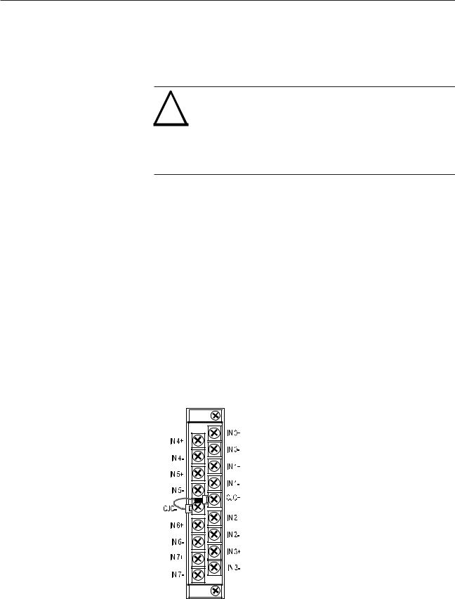
The terminal connections for the CJC sensor are shown below:

14 |
Compact IO™ Universal Input module |
|
|
Step 4: Configure the module. |
Reference |
Chapter 4
(Module Data, Status, and Channel
Configuration)
Circuit jumpers are located on the module to change the input path from current to voltage.
The configuration file is typically modified using the programming software compatible with your controller. It can also be modified through the control program, if supported by the controller. See Channel Configuration in chapter 4 for more information.
Step 5: Go through the startup procedure. |
Reference |
Chapter 5 (Diagnostics and Troubleshooting)
1.Apply power to the controller system.
2.Download your program, which contains the universal module configuration settings, to the controller.
3.Put the controller in Run mode. During a normal start-up, the module status LED turns on.
NOTE If the module status LED does not turn on, cycle power. If the condition persists, contact your local distributor or Spectrum Controls for assistance.
Step 6: Monitor the module |
|
status to check if the module |
Reference |
is operating correctly |
|
|
Chapter 5 (Diagnostics and |
|
Troubleshooting) |
Module and channel configuration errors are reported to the controller. These errors are typically reported in the controller’s I/O status file. Channel status data is also reported in the module’s input data table, so these bits can be used in your control program to flag a channel error.
Chapter 2: Quick Start for Experienced Users |
15 |
16 |
Compact IO™ Universal Input module |
Chapter 3
Installation and Wiring
This chapter tells you how to:
·determine the power requirements for the module
·avoid electrostatic damage
·install the module
·wire the module’s terminal block
·wire input devices
Compliance to European
Union Directives This product is approved for installation within the European Union and EEA regions. It has been designed and tested to meet the following directives.
EMC Directive
The 1769sc-IF8u module is tested to meet Council Directive 89/336/ EEC Electromagnetic Compatibility (EMC) and the following standards, in whole or in part, documented in a technical construction file:
· EN 61000-6-4
EMC – Generic Emission Standard, Part 2 - Industrial Environment
· EN 61000-6-2
EMC – Generic Immunity Standard, Part 2 - Industrial Environment
This product is intended for use in an industrial environment.
Low Voltage Directive
This product is tested to meet Council Directive 2006/95/EC Low Voltage, by applying the safety requirements of EN 61131-2 Programmable Controllers, Part 2 – Equipment Requirements and Tests. For specific information required by EN61131-2, see the appropriate sections in this publication, as well as the following AllenBradley publications:
·Industrial Automation, Wiring and Grounding Guidelines for Noise Immunity, publication 1770-4.1
·Automation Systems Catalog, publication B113
18 Compact IO™ Universal Input module
Power Requirements |
The module receives power through the bus interface from the +5V dc/ |
||
|
+24V dc system power supply. The maximum current drawn by the |
||
|
module is shown in the table below. |
|
|
|
Module Current Draw |
at 5V dc |
at 24V dc |
|
|
|
|
|
|
150 mA |
45 mA |
General
Considerations Compact I/O is suitable for use in an industrial environment when installed in accordance with these instructions. Specifically, this equipment is intended for use in clean, dry environments (Pollution degree 2(1)) and to circuits not exceeding Over Voltage Category II(2) (IEC 60664-1).(3)
Hazardous Location Considerations
This equipment is suitable for use in Class I, Division 2, Groups A, B, C, D or non-hazardous locations only. The following WARNING statement applies to use in hazardous locations.
!WARNING!
·EXPLOSION HAZARD
·Substitution of components may impair suitability for Class I, Division2.
·Do not replace components or disconnect equipment unless power has been switched off or the area is known to be non-hazardous.
·Do not connect or disconnect components unless power has been switched off or the area is known to be non-hazardous.
·This product must be installed in an enclosure.
·All wiring must comply with N.E.C. article 501-4(b).
(1)Pollution Degree 2 is an environment where, normally, only non-conductive pollution occurs except that occasionally a temporary conductivity caused by condensation shall be expected.
(2)Over Voltage Category II is the load level section of the electrical distribution system. At this level transient voltages are controlled and do not exceed the impulse voltage capability of the product’s insulation.
(3)Pollution Degree 2 and Over Voltage Category II are International Electrotechnical Commission (IEC) designations.

Chapter 3: Installation and Wiring |
19 |
Prevent Electrostatic Discharge
!ATTENTION! Electrostatic discharge can damage integrated circuits or
semiconductors if you touch analog I/O module bus connector pins or the terminal block on the input module. Follow these guidelines when you handle the module:
·Touch a grounded object to discharge static potential.
·Wear an approved wrist-strap grounding device.
·Do not touch the bus connector or connector pins.
·Do not touch circuit components inside the module.
·If available, use a static-safe work station.
·When it is not in use, keep the module in its static-shield bag.
Remove Power
!ATTENTION! Remove power before removing or inserting this module.
When you remove or insert a module with power applied, an electrical arc may occur.
An electrical arc can cause personal injury or property damage by:
·sending an erroneous signal to your system’s field devices, causing unintended machine motion
·causing an explosion in a hazardous environment
Electrical arcing causes excessive wear to contacts on both the module and its mating connector and may lead to premature failure.
Selecting a Location
Reducing Noise
Most applications require installation in an industrial enclosure to reduce the effects of electrical interference. Analog inputs are highly susceptible to electrical noise. Electrical noise coupled to the analog inputs will reduce the performance (accuracy) of the module.
Group your modules to minimize adverse effects from radiated electrical noise and heat. Consider the following conditions when selecting a location for the analog module. Position the module:
20Compact IO™ Universal Input module
•away from sources of electrical noise such as hard-contact switches, relays, and AC motor drives
•away from modules which generate significant radiated heat, such as the 1769-IA16. Refer to the module’s heat dissipation specification.
In addition, route shielded, twisted-pair analog input wiring away from any high voltage I/O wiring.
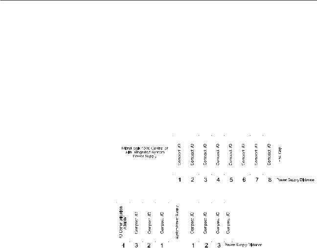
Power Supply Distance
You can install as many modules as your power supply can support. However, all 1769 I/O modules have a power supply distance rating. The maximum I/O module rating is 8, which means that a module may not be located more than 8 modules away from the system power supply.
System Assembly |
|
|
|
|
|
|
|
|
|
|
|
|
|
|
|
|
|
|
|
|
|
|
|
|
|
|
|
|
|
|
|
|
|
|
|
|
|
|
|
|
|
|
|
|
|
|
|
|
|
|
|
|
|
|
|
|
|
|
|
|
|
|
|
|
|
|
|
|
|
|
|
|
|
|
|
|
|
|
|
|
|
|
|
|
|
|
|
|
|
|
|
|
|
|
|
|
|
|
|
|
|
|
|
|
|
|
|
|
|
|
|
|
|
|
|
|
|
|
|
|
|
|
|
|
|
|
|
|
|
|
|
|
|
|
|
|
|
|
|
|
|
|
|
|
|
|
|
|
|
|
|
|
|
|
|
|
|
|
|
|
|
|
|
|
|
|
|
|
|
|
|
|
|
|
|
|
|
|
|
|
|
|
|
|
|
|
|
|
|
|
|
|
|
|
|
|
|
|
|
|
|
|
|
|
|
|
|
|
|
|
|
|
|
|
|
|
|
|
|
|
|
|
|
|
|
|
|
|
|
|
|
|
|
|
|
|
|
|
|
|
|
|
|
|
|
|
|
|
|
|
|
|
|
|
|
|
|
|
|
|
|
|
|
|
|
|
|
|
|
|
|
|
|
|
|
|
|
|
|
|
|
|
|
|
|
|
|
|
|
|
|
|
|
|
|
|
|
|
|
|
|
|
|
|
|
|
|
|
|
|
|
|
|
|
|
|
|
|
|
|
|
|
|
|
|
|
|
|
|
|
|
|
|
|
|
|
|
|
|
|
|
|
|
|
|
|
|
|
|
|
|
|
|
|
|
|
|
|
|
|
|
|
|
|
|
|
|
|
|
|
|
|
|
|
|
|
|
|
|
|
|
|
|
|
|
|
|
|
|
|
|
|
|
|
|
|
|
|
|
|
|
|
|
|
|
|
|
|
|
|
|
|
|
|
|
|
|
|
|
|
|
|
|
|
|
|
|
|
|
|
|
|
|
|
|
|
|
|
|
|
|
|
|
|
|
|
|
|
|
|
|
|
|
|
|
|
|
|
|
|
|
|
|
|
|
|
|
|
|
|
|
|
|
|
|
|
|
|
|
|
|
|
|
|
|
|
|
|
|
|
|
|
|
|
|
|
|
|
|
|
|
|
|
|
|
|
|
|
|
|
|
|
|
|
|
|
|
|
|
|
|
|
|
|
|
|
|
|
|
|
|
|
|
|
|
|
|
|
|
|
|
|
|
|
|
|
|
|
|
|
|
|
|
|
|
|
|
|
|
|
|
|
|
|
|
|
|
|
|
|
|
|
|
|
|
|
|
|
|
|
|
|
|
|
|
|
|
|
|
|
|
|
|
|
|
|
|
|
|
|
|
|
|
|
|
|
|
|
|
|
The module can be attached to the controller or an adjacent I/O module |
||||||||||||||||||||||||||||||||||||||||||||||
|
before or after mounting. For mounting instructions, see Panel |
|||||||||||||||||||||||||||||||||||||||||||||
|
Mounting Using the Dimensional Template, or DIN Rail Mounting. To |
|||||||||||||||||||||||||||||||||||||||||||||
|
work with a system that is already mounted, see Replacing a Single |
|||||||||||||||||||||||||||||||||||||||||||||
|
Module within a System. |
|||||||||||||||||||||||||||||||||||||||||||||
|
The following procedure shows you how to assemble the Compact I/O |
|||||||||||||||||||||||||||||||||||||||||||||
|
system. |
|||||||||||||||||||||||||||||||||||||||||||||
 Loading...