

Page 1
Micro800™ 2 Ch High Current Digital Output Module 20
For Technical Support
USA 440-646-6900
United Kingdom 01908 635230
Australia 1800-809-929
Brazil (55) 11 3618 8800
Europe (49) 2104 960 630
Install Guide
Micro800
2 Ch High Current Digital Output Module
(Catalog Number 2080sc-OW2IHC)
Contents
For More Information ................................................................................. 2
Environment and Enclosure ...................................................................... 3
Prevent Electrostatic Discharge ................................................................ 4
Parts List ................................................................................................... 5
Insert Module into Controller ..................................................................... 6
Wire the Module ........................................................................................ 7
Configuring the Module ............................................................................. 7
Module Input Data ..................................................................................... 7
Module Output Data .................................................................................. 8
™
1705 132nd Ave NE
Bellevue, WA 98005 USA
Tel: 425-746-9481
Fax: 425-641-9473
Email: spectrum@spectrumcontrols.com
Web: www.spectrumcontrols.com
Micro800 is a trademark of Rockwell Automation.
Publication 2080sc-OW2IHC Install Guide – June 2012
© 2012 Spectrum Controls, Inc. Printed in the USA.
Publication 0100188-01 Rev. A
Adding the OW2IHC to CCW .................................................................... 8
Electrical Specifications .......................................................................... 11
Environmental Specifications .................................................................. 13
Hazardous Location Considerations ....................................................... 15
Environnements dangereux .................................................................... 16
Page 2

Micro800™ 2 Ch High Current Digital Output Module 2
For More Information
PLC sample projects and documentation are available on our website at
http://www.spectrumcontrols.com
Micro800™ 2 Ch High Current Digital Output Module 19
Intentionally Left Blank
Publication 0100188-01 Rev. A
Publication 0100188-01 Rev. A
Page 3

Micro800™ 2 Ch High Current Digital Output Module 18
Intentionally Left Blank
Micro800™ 2 Ch High Current Digital Output Module 3
Environment and Enclosure
This equipment is intended for use in a Pollution
Degree 2 industrial environment, in overvoltage
Category II applications (as defined in IEC
publication 60664-1), at altitudes up to 2000 meters
(6562 ft) without derating.
This equipment is considered Group 1, Class A
industrial equipment according to IEC/CISPR
Publication 11. Without appropriate precautions,
there may be potential difficulties ensuring
electromagnetic compatibility in other environments
due to conducted as well as radiated disturbance.
This equipment is supplied as open-type equipment.
It must be mounted within an enclosure that is
suitably designed for those specific environmental
conditions that will be present and appropriately
designed to prevent personal injury resulting from
accessibility to live parts. The enclosure must have
suitable flame-retardant properties to prevent or
minimize the spread of flame, complying with a flame
spread rating of 5VA, V2, V1, V0 (or equivalent) if
non-metallic. The interior of the enclosure must be
accessible only by the use of a tool. Subsequent
sections of this publication may contain additional
information regarding specific enclosure type ratings
that are required to comply with certain product
safety certifications.
In addition to this publication, see:
Industrial Automation Wiring and Grounding
Guidelines, Allen-Bradley publication 1770-
4.1, for additional installation requirements.
NEMA Standards publication 250 and IEC
publication 60529, as applicable, for
explanations of the degrees of protection
provided by different types of enclosure
Publication 0100188-01 Rev. A
Publication 0100188-01 Rev. A
Page 4

Micro800™ 2 Ch High Current Digital Output Module 4
Prevent Electrostatic Discharge
Electrostatic discharge can damage integrated
circuits or semiconductors if you touch bus connector
pins. Follow these guidelines when you handle the
module:
Touch a grounded object to discharge static
potential.
Wear an approved wrist-strap grounding
device.
Do not touch connectors or pins on
component boards.
Do not touch circuit components inside the
module.
If available, use a static-safe work station.
When not in use, keep the module in its
static-shield box.
To comply with the CE Low Voltage Directive (LVD),
all connected I/O must be powered from a source
compliant with the following: Safety Extra Low
Voltage (SELV) or Protected Extra Low Voltage
(PELV).
Micro800™ 2 Ch High Current Digital Output Module 17
Intentionally Left Blank
Publication 0100188-01 Rev. A
Publication 0100188-01 Rev. A
Page 5

Micro800™ 2 Ch High Current Digital Output Module 16
Environnements dangereux
Cet équipement est conçu pour être utilisé dans des environnements de
Classe I, Division 2, Groupes A, B, C, D endroit dangereux ou non
dangereux. La mise en garde suivante s’applique à une utilisation dans
des environnements dangereux.
Micro800™ 2 Ch High Current Digital Output Module 5
Parts List
Your package contains one Micro800 High Current Digital Output Plug-in
Module and one Quick Start guide.
DANGER D’EXPLOSION
La substitution de composants peut
rendre cet équipement impropre à une
utilisation en environnement de Classe
1, Division 2.
Ne pas remplacer de composants ou
déconnecter l'équipement sans s'être
assuré que l'alimentation est coupée
ou que l’endroit soit depourvu de
concentrations inflammables.
Ne pas connecter ou déconnecter des
composants sans s'être assuré que
l'alimentation est coupée.
Ce produit doit être installé dans une
armoire.
Tout le cablage doit agreer la norme
N.E.C. article 501-4(b).
Publication 0100188-01 Rev. A
You can choose to wire the plug-in before inserting it onto the controller,
or wire it once the module is secured in place.
Publication 0100188-01 Rev. A
This equipment is considered Group 1, Class
A industrial equipment according to
IEC/CISPR 11. Without appropriate
precautions, there may be difficulties with
electromagnetic compatibility in residential
and other environments due to conducted
and radiated disturbance.
Be careful when stripping wires. Wire
fragments that fall into the controller could
cause damage. Once wiring is complete,
make sure the controller is free of all metal
fragments before removing the protective
debris strip.
Do not wire more than 2 conductors on any
single terminal.
If you insert or remove the plug-in module
while power is on, an electrical arc can
occur. This could cause an explosion in
hazardous location installations. Be sure that
power is removed or the area is
nonhazardous before proceeding.
Cable length should be less than 10 meters.
Do not insert or remove the plug-in module
while power is applied, otherwise, permanent
damage to equipment may occur.
Page 6

Micro800™ 2 Ch High Current Digital Output Module 6
Micro800™ 2 Ch High Current Digital Output Module 15
Insert Module into Controller
Follow the instructions to insert and secure the plug-in module to the
controller.
1. Position the plug-in module with the terminal block facing the
front of the controller as shown.
2. Snap the module into the module bay.
3. Using a screwdriver, tighten the 10…12 mm (0.39…0.47 in.) M3
self tapping screw to torque specifications.
Hazardous Location Considerations
This equipment is suitable for use in Class I, Division 2, Groups A, B, C,
D hazardous locations or non-hazardous locations only. The following
WARNING statement applies to use in hazardous locations.
EXPLOSION HAZARD
Substitution of components may impair
suitability for Class I, Division 2.
Do not replace components or disconnect
equipment unless power has been
switched off or the area is known to be
free of ignitable concentrations.
Do not disconnect equipment unless
power has been removed or the area is
known to be non-hazardous.
This product must be installed in an
enclosure.
All wiring must comply with N.E.C. article
501-4(b).
Publication 0100188-01 Rev. A
Publication 0100188-01 Rev. A
Page 7

Micro800™ 2 Ch High Current Digital Output Module 14
Environmental Tests Industry Standards Test Level Limits
Signal Ports:
EFT/B immunity IEC 61000-4-4*
± 3 kV @ 5 kHz for 5 minutes
Power Ports:
± 2 kV @ 5 kHz for 5 minutes
Micro800™ 2 Ch High Current Digital Output Module 7
Wire the Module
Follow the wiring diagrams below to wire the module.
CM0 O-0 NC NC CM1 O-1
Surge transient immunity
(Performance Criteria B)
Conducted RF immunity
(Performance Criteria A)
Magnetic Field
(Performance Criteria A)
AC Mains Voltage Dips,
Interruptions and Variations
Safety Tests Industry Standards
UL Safety
UL Hazardous Locations
CE Low Voltage Directive
Signal Ports:
± 2 kV line-earth
IEC 61000-4-5
IEC 61000-4-6
IEC 61000-4-8 30Arms/m
IEC 61000-4-11 Standard
UL 508 Industrial Control Equipment Seventeenth
Edition Dated January 28 1999, with revisions
through July 11, 2005 (ANSI/UL 508-
2005) (NRAQ, NRAQ7)
cUL CSA C22.2 No. 142 -M1987 Process Control
Equipment May 1987
ULH ANSI/ISA–12.12.01–2007 Nonincendive
Electrical Equipment for Use in Class I, Division 2
Hazardous (Classified) Locations
cULH CSA C22.2 No. 213-M1987 - Nonincendive Electrical Equipment for use in Class I
Division 2 Hazardous Locations - March 1987
IEC 61131-2 Programmable Controllers Part 2:
Equipment Requirements and Tests; Second
Edition 2003-02, Section 11-14
Power Ports
± 2kV CM
± 1kV DM
10V rms with 1 kHz sine wave
80%AM from 150 kHz…80 MHz
on signal and power ports
Test Level
Limits
As required
As required
As required
CM0 O-0 NC NC CM1 O-1
L1
or
+DC
L2
or
-DC
Load
L1
or
+DC
Load
L2
or
-DC
Note: In the diagram above, terminals with the same label are internally shorted together.
Example, CM0 (Top Row) and CM0 (Bottom Row) are internally shorted together.
Configuring the Module
The 2080sc-OW2IHC doesn’t really require configuration. It only needs
to be placed into run mode. Write a value of 165 decimal to memory
location 17 (MOD_MODE_CONTROL). See Table 3 for more
information.
Micro 800 controllers running OS firmware
revision 1.12 or older, require a decimal value of
16 be written to memory location 11
(CONTR_OPS_STATUS) before the module will
go into run mode. See program sample on
page 9.
Module Input Data
General module status can be read from memory location 16. Refer to
table below for possible responses.
Table 1 (General Module Status)
Bit Number Description
These 2 bits define module operation mode,
0-1
0: Idle: Module is ready to RUN, and I/O is off.
1: RUN: Module is under RUN, and I/O is on.
2: Error: Error happens, and I/O is off.
3: Busy: Module is busy, cannot go to RUN, and I/O is off.
Publication 0100188-01 Rev. A
Publication 0100188-01 Rev. A
Page 8

Micro800™ 2 Ch High Current Digital Output Module 8
Micro800™ 2 Ch High Current Digital Output Module 13
Module Output Data
The two output channels on the OW2IHC are controlled by memory
location 64, bits 0 and 1 control channels 0 and 1 respectively. See
Table 3 for memory location offsets. The table below describes the state
of each output channel in relation to the control bits.
Table 2 (Output States)
Channel # Bit state Output State
0 OPEN
0
1 CLOSED
0 OPEN
1
1 CLOSED
Adding the OW2IHC to CCW
The 2080sc-OW2IHC is configured for CCW (Connected Components
Workbench) using the PLUGIN_READ and PLUGIN_WRITE instructions
for generic plug-in modules.
The configuration, output data, and status structures discussed in the
sections above, are stored at different memory locations in the module.
The following table lists the memory location offset for each parameter
which is used when configuring the PLUGIN_READ, WRITE, and INFO
instructions.
Table 3 (Parameter Offset)
Parameter
MOD_ID_LO 0 Module ID
MOD_ID_HI 1
VENDOR_ID_LO 2 Vendor ID
VENDOR_ID_HI 3
PRODUCT_TYPE_LO 4
PRODUCT_TYPE_HI 5
PRODUCT_CODE_LO 6
PRODUCT_CODE_HI 7
MOD_REV_LO 8 Minor revision, 1-255
MOD_REV_HI 9 Major revision, 1-127
CONTR_OPS_STATUS
MOD_STATUS
Publication 0100188-01 Rev. A
Offset
(Dec) Comments
Controller operation status information
11
(see Table 4)
Module status register
16
(see
Table 1)
Environmental Specifications
Environmental Tests Industry Standards Test Level Limits
IEC60068-2-1: (Test Ad, Operating Cold),
Temperature (Operating)
Temperature
(Non-operating)
Operating Altitude 2000 meters (6561 feet) Not tested
Humidity (Operating)
Vibration (Operating) IEC60068-2-6: (Test Fc, Operating)
Shock (Operating)
Shock (Non-operating) IEC60068-2-27: (Test Ea, Unpackaged Shock) 50 g
Radiated Emissions CSIPR 11; Group 1, Class A 30MHz – 1GHz
Conducted Emissions
ESD immunity IEC 61000-4-2
Radiated RF immunity IEC 61000-4-3: Level 3
IEC60068-2-2: (Test Bd, Operating Dry Heat),
IEC60068-2-14: (Test Nb, Operating Thermal Shock)
IEC60068-2-1:
(Test Ab, Unpackaged Non-operating Cold),
IEC60068-2-2:
(Test Bb, Unpackaged Non-operating Dry Heat),
IEC60068-2-14:
(Test Na, Unpackaged Non-operating Thermal Shock)
IEC60068-2-30:
(Test Db, Unpackaged Damp Heat):
IEC60068-2-27: (Test Ea, Unpackaged Shock) 10 g
IEC 61000-6-4:2007
Group 1, Class A (AC Mains)
Publication 0100188-01 Rev. A
-20 to 65°C (-4 to 149°F)
-40 to 85°C (-40 to 185°F)
5 to 95% non-condensing
5G
150kHz – 30MHz
4kV Indirect (Coupling Plate)
4kV Contact Discharge (to points
of initial contact)
8kV Air Discharge (to points of
initial contact)
10 V/M with 1 kHz sine-wave
80%AM from 80…2000 MHz
10 V/M with 200 Hz sine-wave
50% Pulse 100%AM @900 MHz
10 V/M with 200 Hz sine-wave
50% Pulse 100%AM @1890 MHz
3 V/M with 1 kHz sine-wave
80%AM from 2000…2700 MHz
Page 9

Micro800™ 2 Ch High Current Digital Output Module 12
Minimum Load 10mA at 5VDC per point.
Initial Contact
Res. of Relay
Expected Life
of
Electrical
Contacts
Switching
Frequency
Bounce Time 1.2 ms average
Maximum Off
State Leakage
Output Delay
Time
(From the time
the module
receives data)
Status
Indicators
Power source 3.3 VDC, 24 VDC from backplane
Input to
backplane
isolation
Channel to
channel
isolation
Power
consumption
Inrush current <120 mA at 3.3V, <120 mA at 24V
Fusing Use external if desired
Terminal block
Wire size
Terminal block
torque
Mounting
torque
Manufacturing RoHS compliant
Dimensions 58.4mm x 29.3mm x 25mm
Status
Indicators
(This value can change due to the switching frequency, environmental conditions, and desired
reliability level, therefore it is recommended to check this with the actual load.)
< 5mΩ typical, 30 mΩ max
100k operations @ 20 times/min, at rated resistive capacity and temperature.
Maximum 1 cycle /3s at rated load (1.5s on, 1.5s off)
1.5mA Maximum
10ms maximum on/off (5 ms typical) excluding bounce time
2 yellow Status Indicators (I/O)
250 VAC continuous, tested at 2300VAC for 1 min.
250 VAC continuous, tested at 1500VAC for 1 minute
<=35 mA at 3.3V, <=20 mA at 24V, <1.5 W
#16 - #30 AWG
0.19 Nm (1.7 lb-in)
0.2 Nm (1.48 lb-in)
Individual OFF/ON Status for each I/O point
Micro800™ 2 Ch High Current Digital Output Module 9
Parameter
MOD_MODE_CONTROL 17 Module Mode Control Register
OUTPUT_DATA 64 Output Data Register
Offset
(Dec) Comments
Table 4(Controller Operation Status Register)
Bit Number Description
0-3 Controller Error info:
0x00: no Error;
0x01: Operation Error;
0x02: Fatal Error
0x03-0x0F: reserved ;
4-5 Controller mode:
0x00: non-RUN mode;
0x01: RUN mode;
0x02-0x03 : reserved ;
6-7 Controller Power info:
0x00: Power O.K.;
0x01: power failure triggered;
0x02-0x03: reserved
The following sample program, written in structured text, demonstrates
how to configure the module in CCW.
u800Slot := 1; (* Slot number for module. *)
(* This section of code is to handle the controller with Firmware earlier than rev 1.13 *)
SYS_INFO_FW(True);
IF (SYS_INFO_FW.Sts.OSMajRev = 1 and SYS_INFO_FW.Sts.OSMinRev <=12) THEN
IF SYS_INFO_FW.Sts.MajErrCode = 0 THEN
ControllerStatus[1] := 2#00010000;
WriteControllerStatus(True,u800Slot,11,1,ControllerStatus);
END_IF;
END_IF;
RunMode[1] := 16#A5; (* Initialize RunMode register *)
WriteModModeControl(true,u800Slot,17,1,RunMode); (* Write A5 Hex to MOD_MODE_CONTROL for run mode*)
ReadModStatus(true,u800Slot,16,1,OW2IHC_S1_ModStatus); (* Read general module status *)
WriteOutputs(True,u800Slot,64,1,OW2IHC_S1_Outputs); (* Write Output states *)
Table 5 (CCW Program Variables)
Variable Name Data Type Dimension
U800Slot UINT NA
SYS_INFO_FW SYS_INFO NA
ControllerStatus USINT [1..1]
WriteControllerStatus Plugin_Write NA
WriteModModeControl Plugin_Write NA
RunMode USINT [1..1]
ReadModStatus Plugin_Read NA
OW2IHC_S1_ModStatus USINT [1..1]
WriteOutputs Plugin_Write NA
OW2IHC_S1_Outputs USINT [1..1]
Publication 0100188-01 Rev. A
Publication 0100188-01 Rev. A
Page 10
Micro800™ 2 Ch High Current Digital Output Module 10
1
The sample project on the previous page, can be downloaded from our
website at http://www.spectrumcontrols.com/downloads.htm
Micro800™ 2 Ch High Current Digital Output Module 11
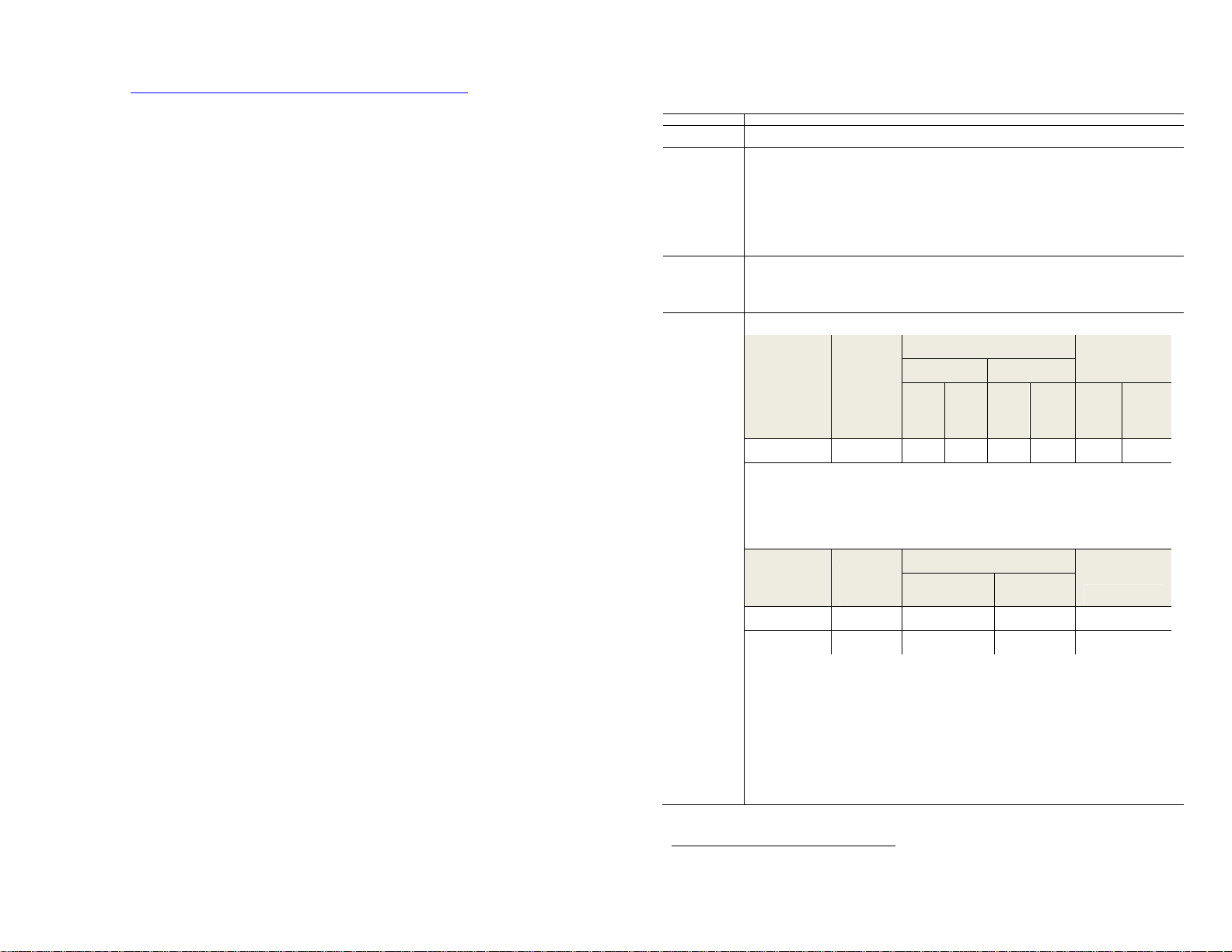
Electrical Specifications
Relay Output Specifications
Description 2 channel relay output module.
Relay
Functionality
Output Current
Rating
(at rated
power)
Output Power
Rating
(Resistive
Inductive Loads
UL Pilot
Duty Contact
Ratings (Power
factor 0.35 or
less for AC):
Additional UL
ratings:
Form A normally open
Resistive load at up to 30° C
10A @ 5-30V dc
10A @ 125V ac
10A @ 250V ac
Resistive load at up to 65° C
6A @ 5-30V dc
6A @ 125V ac
6A @ 250V ac
Resistive load at up to 30° C
300W Maximum for 30.0VDC
1250VA Maximum for 125VAC
2500VA Maximum for 250VAC
Max. current (A)
AC Contact Rating
Code Designation
B300 5 30 3 15 1.5 3600 360
Notes:
a
Power factor 0.35 or less
b
For maximum ratings at voltages between the maximum design value and 120 volts, the maximum
make and break ratings are to be obtained by dividing the volt-amperes rating by the application
voltage. For voltages below 120 volts, the maximum make current is to be the same as for 120 volts,
and the maximum break current is to be obtained by dividing the break volt-amperes by the application
voltage, but these currents are not to exceed the thermal continuous test current.
DC Contact
Rating Code
Designation
R150 1.0 0.22 - 28
R300 1.0 0.22 0.11 28
Notes:
c
The maximum make and break ratings are to be obtained by dividing the volt-ampere rating by the
application voltage, but the current values are not to exceed the thermal continuous test current.
d
Inductive loads as specified in Section 8.2.7 of Industrial Control and Systems; Control Circuit and Pilot
Devices, ANSI/NEMA
ICS5-1993.
1/3 hp, 125 V ac, 250V ac
30V dc Make / Break 2A (Pilot Duty)
250V ac, Make 20A / Break 2A (Pilot Duty)
2A, 250V ac, Tungsten Lamp
2A, 30V dc, Tungsten Lamp
Thermal
continuous test
current (A)
Thermal
continuous
test current
(A)
Make Break Make Break Make Break
Max. make/break current (A)
a,b
Max. VA 120 VAC 240VAC
c,d
Max. make / break
VA 125 VDC 250VDC
1
Connecting surge suppressors across your external load will extend the life of the relay
contacts.
Publication 0100188-01 Rev. A
Publication 0100188-01 Rev. A
 Loading...