

Page 1

User's Manual 0300215-03 Rev. A
User's Manual 0300215-03 Rev . A
Compact™ I/O
Isolated HART
Analog Module
Catalog Number: 1769sc-IF4IH
Page 2

Page 3

User's Manual 0300215-03 Rev. A
Table of Contents
TABLE OF CONTENTS ............................................................................................................................................ I
CHAPTER 1 MODULE OVERVIEW .................................................................................................................. 1-1
SECTION 1.1GENERAL DESCRIPTION .................................................................................................................... 1-1
SECTION 1.2DATA FORMATS ................................................................................................................................. 1-1
SECTION 1.3FILTER FREQUENCIES ........................................................................................................................ 1-2
SECTION 1.4HARDWARE FEATURES ...................................................................................................................... 1-2
1.4.1 General Diagnostic Features.................................................................................................................... 1-3
SECTION 1.5SYSTEM OVERVIEW........................................................................................................................... 1-3
1.5.1 System Operation ...................................................................................................................................... 1-3
SECTION 1.6MODULE OPERATION ........................................................................................................................ 1-4
CHAPTER 2 QUICK START FOR EXPERIENCED USERS ........................................................................... 2-1
SECTION 2.1BEFORE YOU BEGIN .......................................................................................................................... 2-1
SECTION 2.2REQUIRED TOOLS AND EQUIPMENT .................................................................................................. 2-1
SECTION 2.3WHAT YOU NEED TO DO .................................................................................................................. 2-1
CHAPTER 3 INSTALLATION AND WIRING ................................................................................................... 3-1
SECTION 3.1COMPLIANCE TO EUROPEAN UNION DIRECTIVES ............................................................................. 3-1
3.1.1 EMC Directive .......................................................................................................................................... 3-1
3.1.2 Low Voltage Directive .............................................................................................................................. 3-1
3.1.3 CE Safety .................................................................................................................................................. 3-1
SECTION 3.2POWER REQUIREMENTS .................................................................................................................... 3-2
SECTION 3.3GENERAL CONSIDERATIONS .............................................................................................................. 3-2
3.3.1 Hazardous Location Considerations ........................................................................................................ 3-2
3.3.2 Prevent Electrostatic Discharge ............................................................................................................... 3-2
3.3.3 Remove Power .......................................................................................................................................... 3-3
3.3.4 Selecting a Location ................................................................................................................................. 3-3
SECTION 3.4SYSTEM ASSEMBLY ........................................................................................................................... 3-4
SECTION 3.5MOUNTING ......................................................................................................................................... 3-5
3.5.1 Minimum Spacing ..................................................................................................................................... 3-5
3.5.2 Panel Mounting ........................................................................................................................................ 3-5
3.5.3 DIN Rail Mounting ................................................................................................................................... 3-6
SECTION 3.6REPLACING A SINGLE MODULE WITHIN A SYSTEM ........................................................................... 3-7
SECTION 3.7FIELD WIRING CONNECTIONS &SYSTEM WIRING GUIDELINES ...................................................... 3-7
3.7.2 Terminal Door Label ................................................................................................................................ 3-8
3.7.3 Removing and Replacing the Terminal Block ........................................................................................... 3-8
3.7.4 Wiring the Finger-Safe Terminal Block .................................................................................................... 3-8
3.7.5 Wiring the Module .................................................................................................................................... 3-9
3.7.6 Wiring Diagram ...................................................................................................................................... 3-10
3.7.7 Calibration.............................................................................................................................................. 3-10
CHAPTER 4 CONFIGURING THE IF4IH FOR COMPACTLOGIX USING RSLOGIX 5000 ................... 4-1
SECTION 4.1SETTING UP THE GENERIC PROFILE ................................................................................................... 4-1
SECTION 4.2USING THE ADD-ON PROFILE ............................................................................................................ 4- 5
4.2.1 Installing the Add-On profile .................................................................................................................... 4-5
4.2.2 Adding the IF4IH Module To Your Logix Project .................................................................................... 4-6
SECTION 4.3USER DEFINED DATA TYPES ............................................................................................................. 4-7
SECTION 4.4PROJECT TAGS ................................................................................................................................... 4-8
SECTION 4.5SAMPL E PROJECT LADDER ................................................................................................................. 4-9
CHAPTER 5 CONFIGURING THE IF4IH FOR A MICROLOGIX 1500 USING RSLOGIX 500 .............. 5-1
Page 4

Compact™ IO Isolated HART Analog Input Module
User's Manual 0300215-03 Rev. A
ii
S
ECTION 5.1MODULE ADDRESSING ...................................................................................................................... 5-1
SECTION 5.2CONFIGURING THE 1769SC-IF4IH IN A MICROLOGIX 1500SYSTEM ............................................... 5-2
SECTION 5.3USING THE LADDER SAMPL E ............................................................................................................. 5-6
5.3.1 Copying Subroutines from the Sample Project ......................................................................................... 5-6
5.3.2 Copying Ladder from the Sample Project................................................................................................. 5-7
5.3.3 Importing Tag Database and Rung Comments ......................................................................................... 5-8
CHAPTER 6 MODULE DATA, STATUS, AND CHANNEL CONFIGURATION ......................................... 6-1
SECTION 6.1MODULE MEMORY MAP ................................................................................................................... 6-1
SECTION 6.2ACCESSING INPUT IMAGE FILE DATA ................................................................................................ 6-2
SECTION 6.3INPUT DATA FILE ............................................................................................................................... 6-2
6.3.1 Input Data Values (Words 0 to 3) ............................................................................................................. 6-2
6.3.2 Time Stamp Value (Word 4)...................................................................................................................... 6-2
6.3.3 General Status Bits S0 to S3 (Word 5) ...................................................................................................... 6-2
6.3.4 Out of Service Status Bits OS0 to OS3 (Word 5) ...................................................................................... 6-3
6.3.5 Over-Range Flag Bits O0 to O3 (Word 6) ................................................................................................ 6-3
6.3.6 Under-Range Flag Bits U0 to U3 (Word 6) .............................................................................................. 6-3
6.3.7 High Process Alarm Flag Bits H0 to H3 (Word 6) ................................................................................... 6-3
6.3.8 Low Process Alarm Flag Bits L0 to L3 (Word 6) ..................................................................................... 6-4
6.3.9 Pad (Word 7) ............................................................................................................................................ 6-4
6.3.10 HART Data (Words 8 to 27) ................................................................................................................... 6-4
6.3.11 Message Slave Control (Word 28) .......................................................................................................... 6-4
6.3.12 Message Reply Size (Word 29) ............................................................................................................... 6-4
6.3.13 Message Reply Buffer (Words 30…49) ................................................................................................... 6-4
6.3.14 Reserved (Words 50…71) ....................................................................................................................... 6-4
SECTION 6.4MODULE CONFIGURATION ................................................................................................................ 6-5
6.4.1 Real Time Sample Value (Word 0)............................................................................................................ 6-6
6.4.2 General Configuration Bits (Word 1) ....................................................................................................... 6-6
6.4.3 Filter Frequency and General Settings (Words 2, 8, 14, 20) .................................................................... 6-7
6.4.4 Input Type and Data Format (Words 3, 9, 15, 21) ................................................................................. 6-11
6.4.5 Process Alarm High Setpoint (Word s 4, 10, 16, 22) ............................................................................... 6-13
6.4.6 Process Alarm Low Setpoint (Words 5, 11, 17, 23) ................................................................................ 6-13
6.4.7 Process Alarm Deadband (Words 6, 12, 18, 24) .................................................................................... 6-13
6.4.8 Pad (Words 7, 13, 19, 25) ....................................................................................................................... 6-14
6.4.9 Channel X HART Slot Variables 0 & 1 (Words 26, 28, 30, 32) .............................................................. 6-14
6.4.10 Channel X HART Slot Variables 2 & 3 (Words 25, 27, 31, 33) ............................................................ 6-14
SECTION 6.5OUTPUT DATA FILE ......................................................................................................................... 6-15
6.5.1 Unlatch Process High Alarms UH0 to UH3 (Word 0) ........................................................................... 6-15
6.5.2 Unlatch Process Low Alarms UL0 to UL3 (Word 0) .............................................................................. 6-15
6.5.3 Hart Suspend HS0 to HS3 (Word 0) ....................................................................................................... 6-15
6.5.4 Packet Just Scanned (Word 1) ................................................................................................................ 6-15
6.5.5 Message Master Control (Word 2) ......................................................................................................... 6-16
6.5.6 Message Request Size (Word 3) .............................................................................................................. 6-16
6.5.7 Message Request Buffer (Words 4…23) ................................................................................................. 6-16
6.5.8 Reserved (Words 24…45) ....................................................................................................................... 6-16
SECTION 6.6DETERMINING EFFECTIVE RESOLUTION AND RANGE .................................................................... 6-17
SECTION 6.7DETERMINING MODULE UPDATE TIME .......................................................................................... 6-18
6.7.1 Calculating Module Update Time ........................................................................................................... 6-18
CHAPTER 7 ENABLING AND USING HART ON THE 1769SC-IF4IH ......................................................... 7-1
SECTION 7.1CONFIGURING THE MODULE FOR HART ........................................................................................... 7-1
7.1.1 Configuring the IF4IH Module for (Hart Acquisition/Communication)................................................... 7-1
SECTION 7.2HART PACKET DATA ........................................................................................................................ 7-2
7.2.1 How the Module Connects to a Field Device ........................................................................................... 7-2
7.2.2 Auto Acquisition........................................................................................................................................ 7-3
7.2.3 Packet Interval ........................................................................................................................................ 7-10
Page 5

Table of Contents
User's Manual 0300215-03 Rev. A
iii
S
ECTION 7.3SENDING AND RECEIVING MESSAGES .............................................................................................. 7-11
7.3.1 Module Output Tags Used For Messaging ............................................................................................. 7-11
7.3.2 Module Input Tags Used For Messaging ................................................................................................ 7-12
7.3.3 Processing a Message ............................................................................................................................. 7-13
SECTION 7.4MODULE SPECIFIC COMMANDS ....................................................................................................... 7-30
7.4.1 Get HART Device Information ............................................................................................................... 7-30
7.4.2 HART Channel Suspension and Resume ................................................................................................. 7-33
7.4.3 HART Pass-Through Command ............................................................................................................. 7-34
SECTION 7.5HART PROTOCOL OVERVIEW ......................................................................................................... 7-43
7.5.1 Message Format ..................................................................................................................................... 7-43
7.5.2 Sending a HART Command to a Field Device via Pass-through ........................................................... 7-45
CHAPTER 8 PROGRAMMING EXAMPLES .................................................................................................... 8-1
SECTION 8.1COMPACTLOGIX ................................................................................................................................ 8-1
8.1.1 Reset/Reconfig .......................................................................................................................................... 8-1
8.1.2 Swap Byte Order ....................................................................................................................................... 8-3
8.1.3 Converting Unpacked ASCII to Packed ASCI I ......................................................................................... 8-3
SECTION 8.2MICROLOGIX 1500 ............................................................................................................................ 8-6
8.2.1 MAIN Routine ........................................................................................................................................... 8-7
8.2.2 PACKETS Routine .................................................................................................................................... 8-8
8.2.3 MSG_TO_MOD Routine ........................................................................................................................ 8-11
8.2.4 SRC_CHECK Routine ............................................................................................................................ 8-28
8.2.5 DEST_CHECKSUM Routine .................................................................................................................. 8-30
8.2.6 HART_MSG Routine ............................................................................................................................... 8-32
8.2.7 WORD_BYTE Routine ............................................................................................................................ 8-43
8.2.8 HART_CHECK Routine .......................................................................................................................... 8-46
8.2.9 BYTE_WORD Routine ............................................................................................................................ 8-48
CHAPTER 9 DIAGNOSTICS AND TROUBLESHOOTING ............................................................................ 9-1
SECTION 9.1SAFETY CONSIDERATIONS................................................................................................................. 9-1
9.1.1 Indicator Lights ........................................................................................................................................ 9-1
9.1.2 Stand Clear of Equipment ......................................................................................................................... 9-1
9.1.3 Program Alteration ................................................................................................................................... 9-1
9.1.4 Safety Circuits ........................................................................................................................................... 9-1
SECTION 9.2MODULE OPERATION VS.CHANNEL OPERATION .............................................................................. 9-2
SECTION 9.3POWER-UP DIAGNOSTICS .................................................................................................................. 9-2
SECTION 9.4CHANNEL DIAGNOSTICS .................................................................................................................... 9-2
9.4.1 Invalid Channel Configuration Detection ................................................................................................ 9-2
9.4.2 Over or Under-Range Detection ............................................................................................................... 9-3
SECTION 9.5NON-CRITICAL VS.CRITICAL MODULE ERRORS ............................................................................... 9-3
SECTION 9.6MODULE ERROR DEFINITION TABLE ................................................................................................. 9-3
9.6.1 Module Error Field................................................................................................................................... 9-3
9.6.2 Extended Error Information Field ............................................................................................................ 9-4
SECTION 9.7ERROR CODES .................................................................................................................................... 9-4
SECTION 9.8MODULE INHIBIT FUNCTION ............................................................................................................. 9-5
APPENDIX A MODULE SPECIFICATIONS .................................................................................................... A-1
SECTION A.1 ELECTRICAL SPECIFICATIONS .......................................................................................................... A-1
SECTION A.2 ENVIRONMENTAL SPECIFICATIONS ................................................................................................. A- 2
SECTION A.3 REGULATORY COMPLIANCE ............................................................................................................ A-3
APPENDIX B HART UNIVERSAL AND COMMON PRACTICE COMMANDS ......................................... B-1
Page 6

Compact™ IO Isolated HART Analog Input Module
User's Manual 0300215-03 Rev. A
iv
Page 7

User's Manual 0300215-03 Rev. A
Preface
Read this preface to familiarize yourself with the rest of the manual. This preface covers
the following topics:
• Who should use t his manual
• How to use this manual
• Related publications
• Conventions used in this manual
• Rockwell Automation support
Who Should
Use This Manual
Use this manual if you are responsible for designing, installing, programming, or
troubleshooting control systems that use Allen-Bradle y Compact™ I/O and/or
compatible controllers, such as MicroLogix 1500 or CompactLogix.
How to Use
This Manual
As much as possible, we organized this manual to explain, in a task-by-task manner, how
to install, configure, program, operate and troubleshoot a control system using the
1769sc-IF4IH.
Related
Documentation
The table below provides a listing of publications that contain important information
about MicroLogix 1500 syste ms.
Document Title Document Number
MicroLogix™ 1500 User Manual 1764-UM001A-US-P
1769 Compact Discrete Input/Output Modules
Product Data
1769-2.1
MicroLogix™ 1500 System Overview 1764-SO001B-EN-P
Compact™ I/O System Overview 1769-SO001A-EN-P
CompactLogix User Manual 1769-UM007B-EN-P
Allen-Bradley Programmable Controller
Grounding and Wiring Guidelines
1770-4.1
If you would like a manual, you can:
• Download a free electronic version from the internet at
www.theautomationbookstore.com
• Purchase a printed manual by:
o Contacting your local distributor or Rockwell Automation representative
o Visiting www.theautomationbookstore.com and placing your order
o Calling 1.800.963.9548 (USA/Canada) or 001.330.725.1574 (Outside
USA/Canada)
Page 8

Compact IO™ Isolated HART Analog Input Module
User's Manual 0300215-03 Rev. A
ii
Conventions
Used in This
Manual
The following conventions are used throughout this manual:
• Bulleted lists (like this one) provide information not procedural steps.
• Numbered lists provide sequential steps or hierarchical information.
• Italic type is used for emphasis
• Bold type identifies headings and sub-headings
•
!
Attention
Are used to identify critical information to the reader
Page 9

User's Manual 0300215-03 Rev. A
Chapter 1
Module Overview
This chapter describes the 1769sc-IF4IH isolated HART analog input module and
explains how the module reads current, voltage, and current wit h H ART input data.
Included is information about:
• The module’s hardware and diagnostic features
• An overview of the system and module operation
Section 1.1
General
Description
The IF4IH is a four channel isolated module that allows each channel to be configured
independently for either current, voltage, or current with HART communication. The
module digitally converts and stores analog data from any combination mentioned above
as well as HART data for channels configured for HART. Each input channel is
individually configured via software for a specific input device, data forma t and filter
frequency, and provides over-range and under-range detection and indication.
The tables below list the input types and their associated ranges.
Table 1-1
Current Input Types
0 t o 20mA
4mA to 20mA
Table 1-2
Volt age Input Types
± 10 V
0 to 10 V
0 t o 5 V
1 t o 5 V
Section 1.2
Data Formats
The data can be configured on board each module as:
• Engineering un it s
• Scaled-for-PID
• Percent of full-scale
• Raw/proportional data
Page 10
Compact™ IO Isolated HART Analog Input Module
User's Manual 0300215-03 Rev . A
1-2
Section 1.3
Filter
Frequencies
The module uses a digital filter that provides high frequency noise rejection for the input
signals. The filter is programmable, allowing you to select from five different filter
frequencies for each channel:
• 28.5 Hz
• 50 Hz
• 60 Hz
• 300 Hz
• 360 Hz
Section 1.4
Hardware
Features
The module contains a removable terminal block. Channels are wired as differential
inputs (i.e. each channel will have a dedicated ground).
Note: A jumper must be installed on the terminal block between CH- and CH-iRtn for
all current input ranges.
Module configuration is done via the controller’s programming software. In addition,
some controllers support configuration via the user program. In either case, the module
configuration is stored in the memory of the controller. Refer to your controller’s user
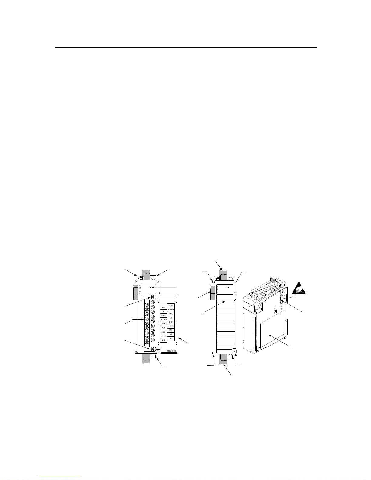
manual for more information. The illustration below shows the module’s hardware
features.
Figure 1-1
5a
9
5b
6
7a
7b
8b
7b
8a
7a
OK
HART
10a
10b
4
10
2b
3
2a
1
DANGER
Do Not Remov e RTB Under
Power Unless Are a is No nHazardous
Ensure Adjacent Bus
Lever is Unlatched/
Latched Before/After
Removing/I nserting
Module
OK
HART
Item Description
1 bus lever
2a upper panel mounting tab
2b lower panel mounting tab
3 module status LED
4 module door with terminal identification label
Page 11

Chapter 1: Module Overview
User's Manual 0300215-03 Rev . A
1-3
5a movable bus connector (bus interface) with female pins
5b stationary bus connector (bus interface) with male pins
6 nameplate label
7a upper tongue-and-groove slots
7b lower tongue-and-groove slots
8a upper DIN rail latch
8b lower DIN rail latch
9 write-on label for user identification tags
10 removable termi nal block (RTB) with finger-safe cover
10a RTB upper retaining screw
10b RTB lower retaining screw
1.4.1 General Diagnostic Features
The module contains a diagnostic LED that helps you identify the source of problems that
may occur during power-up or during normal channel operation. The LED indicates both
status and power. Power-up and channel diagnostics are explained in Chapter 9
Diagnostics and Troubleshooting.
Section 1.5
System
Overview
The modules communicate to the controller through the bus interface. The modules also
receive 5 and 24V dc power through the bus interface.
1.5.1 System Operation
At power-up, the module performs a check of its internal circuits, memory, and basic
functions. During this time, the module status LED remains off. If no faults are found
during power-up diagnostic s, the module status LED is turned on.
After power-up checks are complete, the module waits for valid channel configuration
data. If an invalid configuration is detected, the module generates a configuration error.
Once a channel is properly configured and enabled, it continuously converts the input
data to a value within the range selected for that channel.
Each time a channel is read by the input module, that data value is tested by the module
for an over-range, under-range, open-circuit, or “i nput data not valid” condition. If such a
condition is detected, a unique bit is set in the channel status word. The channel status
word is described in Section 6.3 Input Data File.
Using the module image table, the controller reads the two’s comp lement binary
converted input data from the module. This typically occurs at the end of the program
scan or when commanded by the control program. If the controller and the module
determine that the data transfer has been made without error, the data is used in the
control program.
Page 12
Compact™ IO Isolated HART Analog Input Module
User's Manual 0300215-03 Rev . A
1-4
Section 1.6
Module
Operation
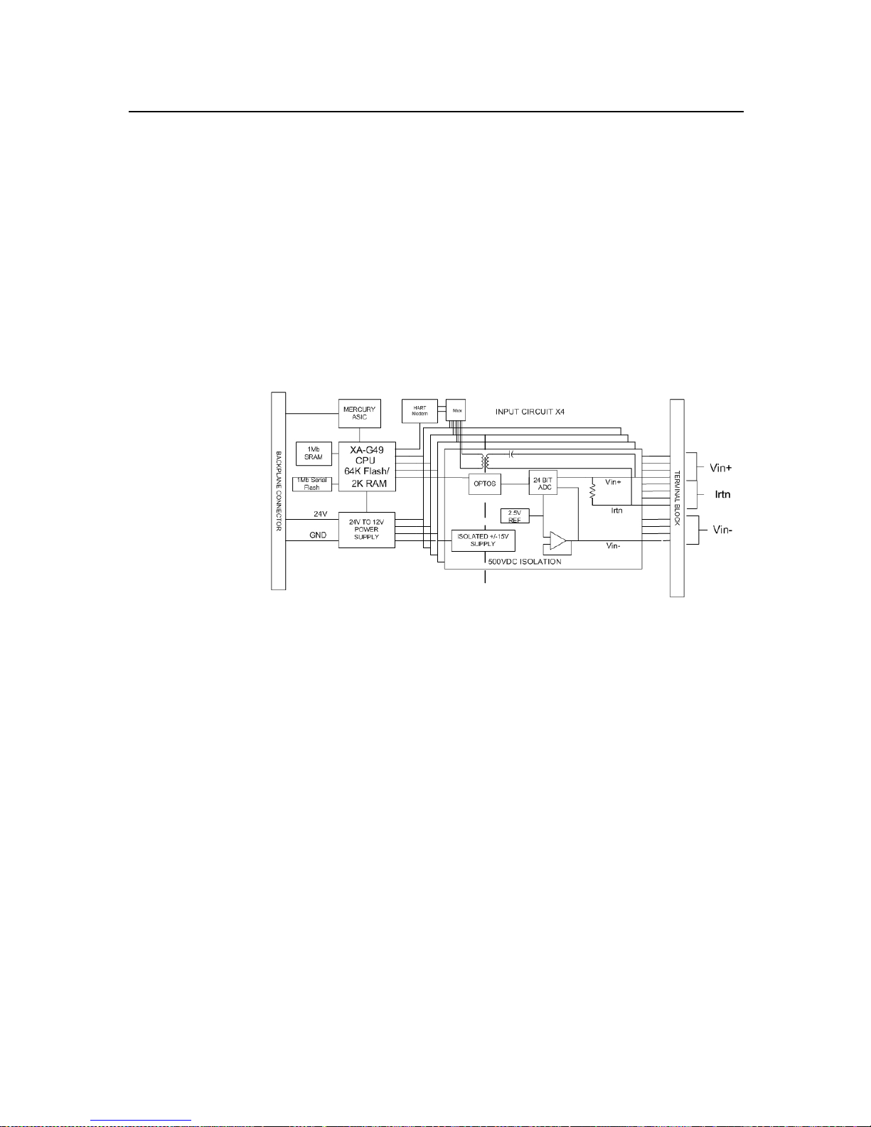
When the module receives the input from an analog device, the module’s circuitry
multiplexes the input into an A/D converter. The converter reads the signal and converts
it as required for the type of input. If HART is enabled on a channel, the HART data is
acquired my means of an onboard HART mode m.
Note: The HART data is acquired asynchronously from the analog acquisition process
and therefore does not directly effect the analog update time.
See the block diagram below.
Figure 1-2
The module is designed to support up to 4 isolated channels which can be independe ntly
configured for voltage, current, or current with HART. The module converts the analog
values directly into digital counts which are viewed and accessed from within the PLC
via controller input tags.
The HART data, if enabled, is converted directly to a block of twent y controller input
tags. The data within this block of twenty tags is multiplexed. For information on HART
and how to demultiplex the HART data, refer to Chapter 7.
Page 13

User's Manual 0300215-03 Rev . A
Chapter 2
Quick Start for Experienced
Users
Section 2.1
Before
You Begin
This chapter can help you get started using the 1769sc-IF4IH isolated HART analog
input module. We base the procedures here on the assumption that you have an
understanding of Allen-Bradley controllers. You should understand electronic process
control and be able to interpret the ladder logic instructions required to generate the
electronic signals that control your application.
Because it is a start-up guide for experienced users, this chapter does no t contain detailed
explanations about the procedures listed. It does, however, reference other chapters in
this book where you can get more information about applying the procedures described in
each step.
If you have any questions or are unfamiliar with the terms used or concepts presented in
the procedural steps, always read the referenced chapters and other recommended
documentation before trying to apply the information.
Section 2.2
Required
Tools and
Equipment
Have the following tools and equipment ready:
• Medium blade or cross-head screwdriver
• Analog input device
• Shielded, twisted-pair cable for wiring (Belden™ 8761 or equivalent for voltage and
current inputs)
• Controller (for example, a MicroLogix™ 1500 or CompactLogix™ controller)
• Programming device and software (for example, RSLogix 500™ or RSLogix
5000™)
Section 2.3
What You
Need To Do
This chapter covers:
1. Ensuring that your power supply is adequate
2. Attaching and locking the module
3. Wiring the module
4. Configuring the module
5. Going through the startup procedure
6. Monitoring module operation
Page 14
Chapter 2: Quick Start for Experienced Users
User's Manual 0300215-03 Rev . A
2-2
Step 1: Ensure that your 1769 system
power supply
1
has sufficient current
output to support your system
configuration. Reference
Chapter 3 (Installation and Wiring)
The modules maximum current draw is shown below:
5V dc 24V dc
175 mA 60 mA
NOTE: The module cannot be located more than 8 modules away from the system
power supply.
Step 2: Attach and lock the module. Reference
Chapter 3 (Installation and Wiring)
Remove power before removing or inserting this module. If you remove or insert a
module with power applied an electrical arc may occur.
NOTE: The module can be panel or DIN rail mounted. Modules can be assembled
before or after mounting.
!
Attention
Remove power before removing or inserting this module. If you remove
or insert a module with power applied an electrical arc may occur.
1. Check that the bus lever of the module to be installed is in the unlocked (fully right)
position.
2. Use the upper and lower tongue-and-groove slots (1) to secure the modules together
(or to a controller).
3. Move the module back along the tongue-and-groove slots until the bus connectors
(2) line up with each other.
4. Push the bus lever back slightly to clear the positioning tab (3). Use your fingers or a
small screwdriver.
1
The system power supply could be a 1769-PA2, -PB2, -PA4, -PB4, or the internal supply of the MicroLogix 1500
packaged controller.
Page 15

Chapter 2: Quick Start For Experienced Users
User's Manual 0300215-03 Rev . A
2-3
5. To allow communication between the controller and module, move the bus lever
fully to the left (4) until it clicks. Ensure it is locked firmly in place.
6. Attach a n end cap terminator (5) to the last module in the system by using the
tongue-and-groove slots as before.
7. Lock the end cap bus terminator (6).
!
Attention
When attaching I/O modules it is very important that the bus connectors
are securely locked together to ensure proper electrical connection.
!
Attention
A 1769-ECR or 1769-ECL right or left end cap respectively must be used
to terminate the end of the 1769 communication bus.
Step 3: Wire the module. Reference
Chapter 3 (Installation and Wiring)
Follow the guidelines below when wiring the module.
General
• Power and input wiring must be in accordance with Class 1, Division 2 wiring
methods, Article 501-4(b) of the National Electric Code, NFPA 70, and in
accordance with the authority having jurisdiction.
• Channels are isolated from one another by ±500V dc maximum.
• Route field wiring away from any other wiring and keep it as far as possible from
sources of electrical noise, such as motors, transformers, contactors, and ac devices.
As a general rule, allow at least 15.2 cm (6 in.) of separation for every 120V of
power.
• Routing field wiring in a grounded conduit can reduce electrical noise.
• If field wiring must cross ac or power cables, ensure that they cross at right angles.
Terminal Block
• For voltage and current sensors, use Belden 8761 shielded, twisted-pair wire (or
equivalent) to ensure proper operation and high immunity to electrical noise.
• To ensure optimum accuracy, limit overall cable impedance by keeping a cable as
short as possible. Locate the module as close to input devices as the application
permits.
Grounding
• This product is intended to be mounted to a well-grounded mounting surface such as
a metal panel. Additional grounding connections from the module’s mounting tabs or
DIN rail (if used) are not required unless the mounting surface cannot be grounded.
• Keep cable shield connections to ground as short as possible.
• Ground the shield drain wire at one end only. The preferred location is as follows.
• Refer to Industrial Automation Wiring and Grounding Guidelines, Allen-Bradley
publication 1770-4.1, for additional information.
Page 16

Chapter 2: Quick Start for Experienced Users
User's Manual 0300215-03 Rev . A
2-4
The terminal block layout is shown below:
Figure 2-1
N/C
Ch1-iRtn
N/C
Ch3-iRtn
Ch0+
N/C
Ch0-iRtn
Ch0-
Ch1+
N/C
Ch2-iRtn
Ch2-
Ch3+
Ch3-
N/C
N/C
Ch2+
Ch1-
Step 4: Configure the module for the
proper controller.
Reference
Chapter 4 (Configuring the IF4IH for
CompactLogix Using
RSLogix 5000) or Chapter 5 (Configuring
the IF4IH for a MicroLogix 1500 Using
RSLogix 500)
Step 5: Configure the module. Reference
Chapter 6 (Module Data, Status, and
Channel Configuration)
The configuration file is typically modified using the programming software compatible
with your controller. It can also be modified through the control program, if supported by
the controller. See Section 6.4 Module
Configuration for more information.
Step 6: Go through the startup
procedure. Reference
Chapter 9 (Diagnostics and
Troubleshooting)
1. Apply power to the controller system.
2. Download your program, which contains the Isolated HART module configuration
settings, to the controller.
3. Put the controller in Run mode. During a normal start-up, the module status LED
turns on.
NOTE: If the module status LED does not turn on, cycle power. If the conditio n
persists, contact your local distributor or Spectrum Controls for assistance.
Page 17

Chapter 2: Quick Start For Experienced Users
User's Manual 0300215-03 Rev . A
2-5
Step 7: Monitor the module status to
check if the module is operating
correctly Reference
Chapter 9 (Diagnostics and
Troubleshooting)
Module and channel configuration errors are reported to the controller. These errors are
typically reported in the controller’s I/O status file. Channel status data is also reported in
the module’s input data table, so these bits can be used in your control program to flag a
channel error.
Page 18

Chapter 2: Quick Start for Experienced Users
User's Manual 0300215-03 Rev . A
2-6
Page 19

User's Manual 0300215-03 Rev . A
Chapter 3
Installation and Wiring
This chapter explains how to:
• Determine the power requirements for the module
• Avoid electrostatic damage
• Install the module
• Wire the module’s terminal block
• Wire input devices
Section 3.1
Compliance to
European Union
Directives
This product is approved for installation within the European Union and EEA regions. It
has been designed and tested to meet the following directives.
3.1.1 EMC Directive
The 1769sc-IF4IH module is tested to meet Council Directive 89/336/EEC
Electromagnetic Compatibility (EMC) and the following standards, in whole or in part,
documented in a technical construction file:
• EN 50081-2 EMC – Generic Emission Standard, Part 2 - Industrial Environment
• EN 50082-2 EMC – Generic Immunity Standard, Part 2 - Industrial Environment
This product is intended for use in an industrial environment.
3.1.2 Low Voltage Directive
This product is tested to meet Council Directive 73/23/EEC Low Voltage, by applying
the safety requirements of EN 61131-2 Programmable Controllers, Part 2 – Equipment
Requirements and Tests. For specific information required by EN61131-2, see the
appropriate sections in this publication, as well as the following Allen-Bradley
publications:
• Industrial Automation, Wiring and Grounding Guidelines for Noise Immunity,
publication 1770-4.1
• Automation Systems Catalog, p ublication B113
3.1.3 CE Safety
This product is designed to, and verified compliance with, European Union Safety
Standards:
• EN61131-2
• EN61010-1
Page 20

Compact IO™ Isolated HART Analog Input Module
User's Manual 0300215-03 Rev . A
3-2
Section 3.2
Power
Requirements
The module receives power through the bus inter face from the +5V dc/ +24V dc system
power supply. The maximum current drawn by the module is shown in the table below.
Module Current Draw at 5V dc at 24V dc
175 mA 60 mA
Section 3.3 General
Considerations
Compact I/O is suitable for use in an industrial environment when installed in accordance
with these instructions. Specifically, this equipment is intended for use in clean, dry
environments (Pollution degree 2
1
and to circuits not exceeding Over Voltage Category
II
2
(IEC 60664-1)
3
3.3.1 Hazardous Location Considerations
This equipment is suitable for use in Class I, Division 2, Groups A, B, C, D or nonhazardous locations only. The following WARNING statement applies to use in
hazardous locations.
!
Attention
· EXPLOSION HAZARD
· Substitution of components may impair suitability for Class I,
Division2.
· Do not replace components or disconnect equipment unless power has
been switched off or the area is known to be non-hazardous.
· Do not connect or disconnect components unless power has been
switched off or the area is known to be non-hazardous.
· This product must be installed in an enclosure.
· All wiring must comply with N.E.C. article 501-4(b).
3.3.2 Prevent Electrostatic Discharge
!
Attention
Electrostatic discharge can damage integrated circuits or
semiconductors if you touch analog I/O module bus connector pins or
the terminal block on the input module. Follow these guidelines when
you handle the module:
Touch a grounded object to discharge static potential.
Wear an approved wrist-strap grounding device.
Do not touch the bus connector or connector pins.
Do not touch circuit components inside the module.
If available, use a static-safe work station.
When it is not in use, keep the module in its static-shield bag.
1
Pollution Degree 2 is an environment where, normally, only non-conductive pollution occurs except that
occasionally a temporary conductivity caused by condensation shall be expected.
2
Over Voltage Category II is the load level section of the electrical distribution system. At this level transient
voltages are controlled and do not exceed the impulse voltage capability of the product’s insulation.
3
Pollution Degree 2 and Over Voltage Category II are International Electrotechnical Commission (IEC)
designations.
Page 21
Chapter 3: Installation and Wiring
User's Manual 0300215-03 Rev . A
3-3
3.3.3 Remove Power
!
Attention
Remove power before removing or inserting this module. When you
remove or insert a module with power applied, an electrical arc may
occur. An electrical arc can cause personal injury or property damage
by:
Sending an erroneous signal to your system’s field devices, causing
unintended machine motion
Causing an explosion in a hazardous environment
Electrical arcing causes excessive wear to contacts on both the module
and its mating connector and may lead to premature failure.
3.3.4 Selecting a Location
Reducing Noise
Most applications require installation in an industrial enclosure to reduce the effects of
electrical interference. Analog inputs are highly susceptible to electrical noise. Electrical
noise coupled to the analog inputs will reduce the performance (accuracy) of the module.
Group your modules to minimize adverse effects from radiated electrical noise and heat.
Consider the following conditions when selecting a location for the analog module.
Position the module:
• Away from sources of electrical noise such as hard-contact switches, relays, and AC
motor drives
• Away from modules which generate significant radiated heat, such as the 1769-IA16.
Refer to the module’s heat dissipation specification.
In addition, route shielded, twisted-pair analog input wiring away from any high voltage
I/O wiring.
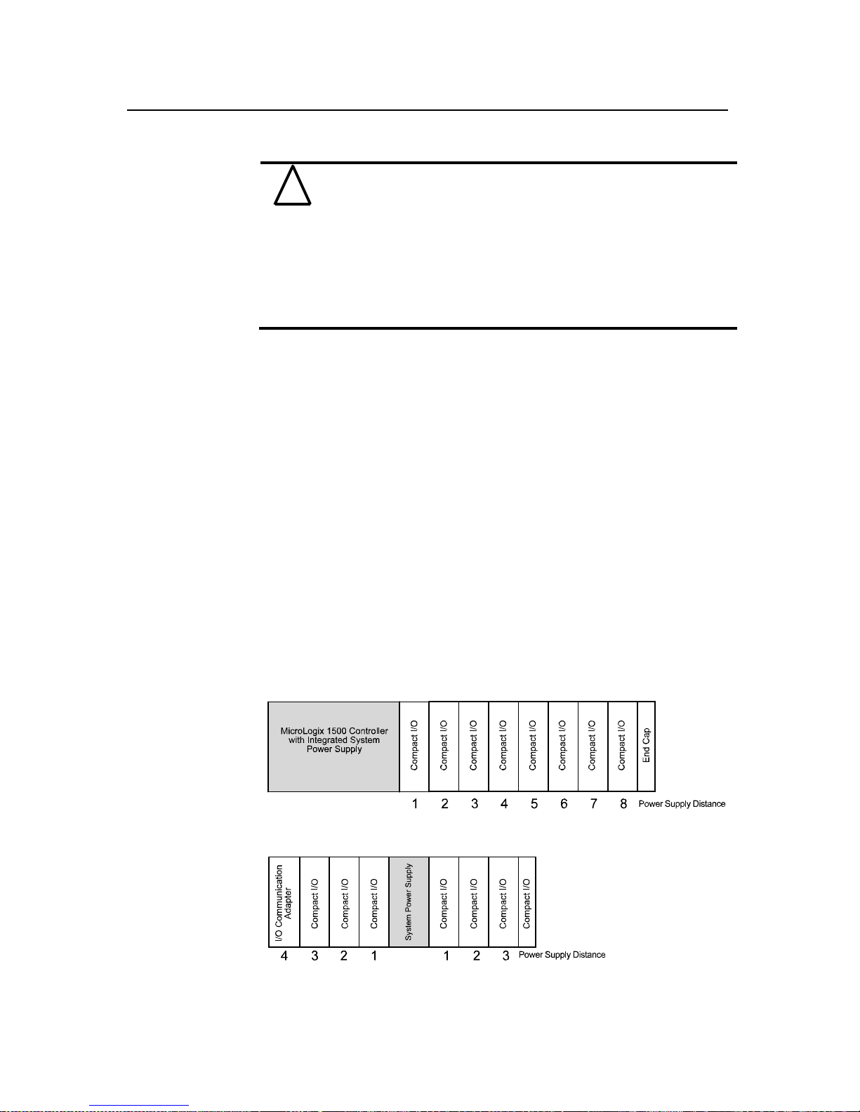
Power Supply Distance
You can install as many modules as your power supply can support. However, all 1769
I/O modules have a power supply distance rating. The maximum I/O module rati ng is 8,
which means that a module may not be located more than 8 modules away from the
system power supply.
Figure 3-1
Page 22
Compact IO™ Isolated HART Analog Input Module
User's Manual 0300215-03 Rev . A
3-4
Section 3.4
System Assembly
The module can be attached to the controller or an adjacent I/O module before or after
mounting. For mounting instructions, see Panel Mounting Using the Dimensional
Template, or DIN Rail Mounting. To work with a system that is already mounted, see
Replacing a Single Module within a System.
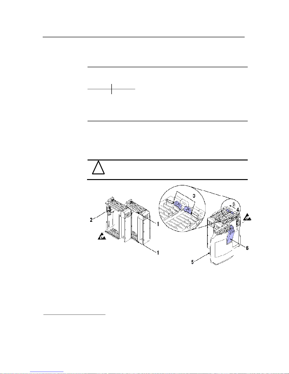
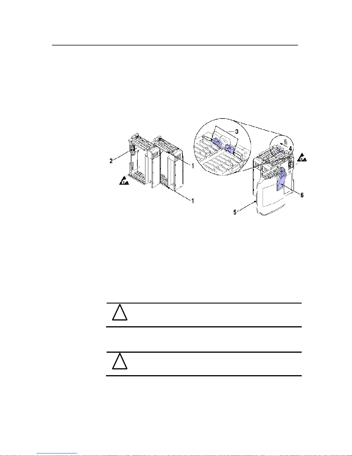
The following procedure shows you how to assemble the Compact I/O system.
Figure 3-2
1. Disconnect power.
2. Check that the bus lever of the module to be installed is in the unlocked (fully right)
position.
NOTE: If the module is being installed to the left of an existing module, check that the
right-side adjacent module’s bus lever is in the unlocked (fully right) p osition.
3. Use the upper and lower tongue-and-groove slots (1) to secure the modules together
(or to a controller).
4. Move the module back along the tongue-and-groove slots until the bus connectors
(2) line up with each other.
5. Push the bus lever back slightly to clear the positioning tab (3). Use your fingers or a
small screwdriver.
6. To allow communication between the controller and module, move the bus lever
fully to the left (4) until it clicks. Ensure it is locked firmly in place.
!
Attention
When attaching I/O modules, it is very important that the bus
connectors are securely locked together to ensure proper electrical
connection.
7. Attach a n end cap terminator (5) to the last module in the system by using the
tongue-and-groove slots as before.
8. Lock the end cap bus terminator (6).
!
Attention
A 1769-ECR or 1769-ECL right or left end cap respectively must be
used to terminate the end of the bus.
Page 23
Chapter 3: Installation and Wiring
User's Manual 0300215-03 Rev . A
3-5
Section 3.5
Mounting
!
Attention
During panel or DIN rail mounting of all devices, be sure that all debris
(metal chips, wire strands, etc.) is kept from falling into the module.
Debris that falls into the module could cause damage at power up.
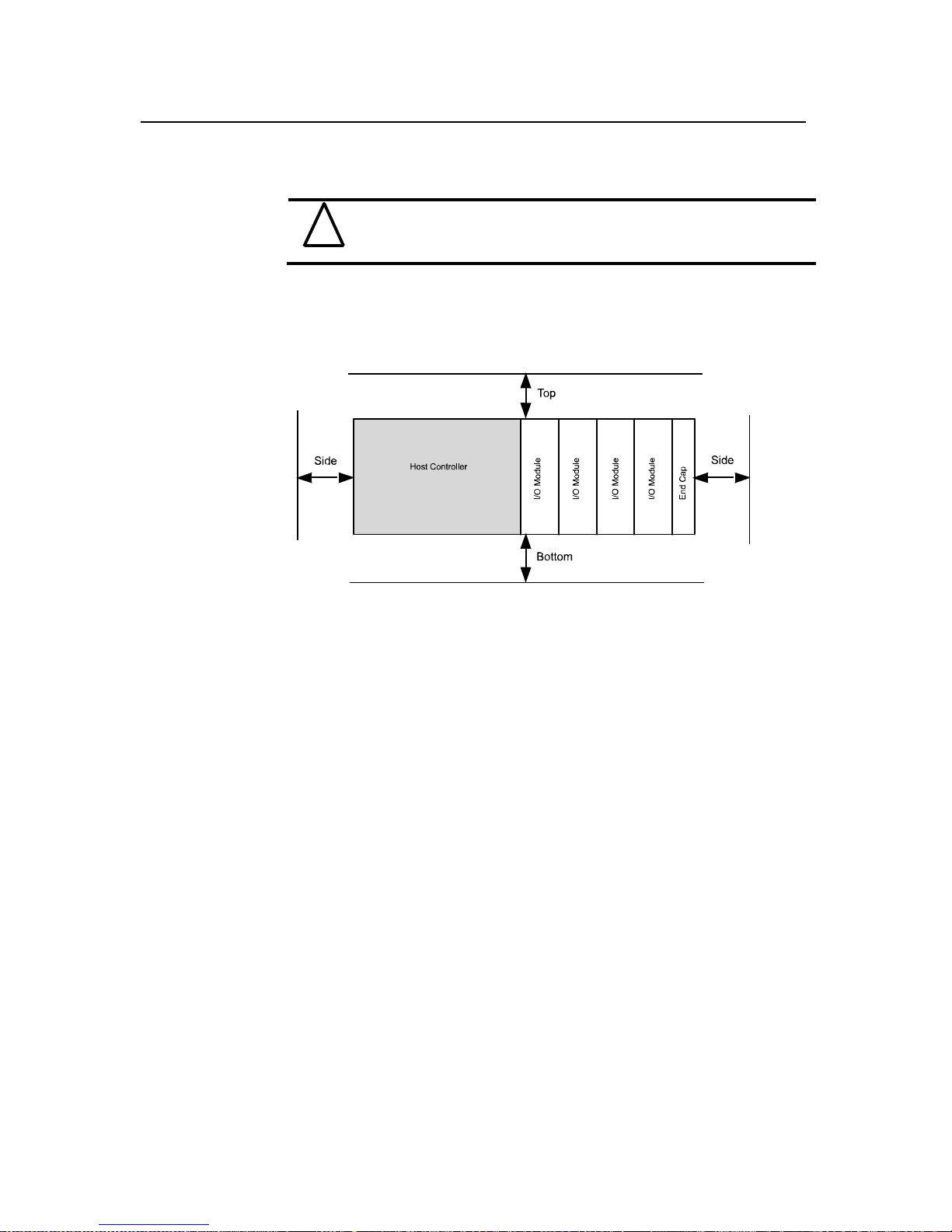
3.5.1 Minimum Spacing
Maintain spacing from enclosure walls, wireways, adjacent equipment, etc. Allow 50 mm
(2 in.) of space on all sides for adequate ventilation, as shown below:
Figure 3-3
3.5.2 Panel Mounting
Mount the module to a panel using two screws per module. Use M4 or #8 panhead
screws. Mounting screws are required on every module.
Page 24
Compact IO™ Isolated HART Analog Input Module
User's Manual 0300215-03 Rev . A
3-6
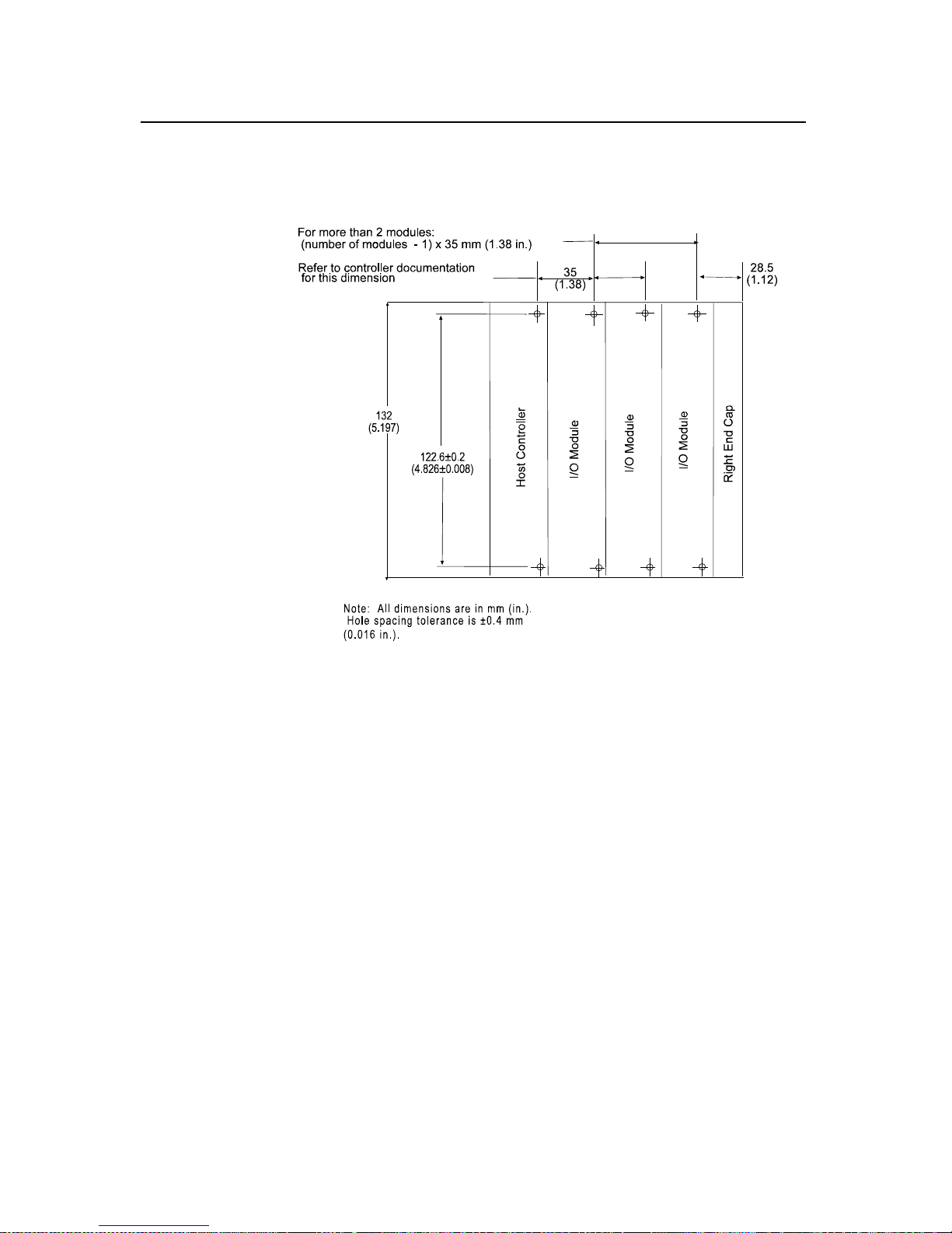
Panel Mounting Using the Dimensional Template
Figure 3-4
Panel Mounting Procedure Using Modules a s a Template
The following procedure allows you to use the assembled modules as a template for
drilling holes in the panel. If you have sophisticated panel mounting equipment, you can
use the dimensional template provided on the previous page. Due to module mounting
hole tolerance, it is important to follow these procedures:
1. On a clean work surface, assemble no more than three modules.
2. Using the assembled modules as a template, carefully mark the center of all module-
mounting holes on the panel.
3. Return the assembled modules to the clean work surface, including any previously
mounted module s.
4. Drill and tap the mounting holes for the recommended M4 or #8 screw.
5. Place the modules back on the panel, and check for proper hole alignment.
6. Attach the modules to the panel using the mounting screws.
NOTE If mounting more modules, mount only the last one of this group and put the
others aside. This reduces remounting time during drilling and tapping of the next
group.
7. Repeat steps 1 to 6 for any remaining modules.
3.5.3 DIN Rail Mounting
The module can be mounted using the following DIN rails:
• 35 x 7.5 mm (EN 50 022 - 35 x 7.5), or
• 35 x 15 mm (EN 50 022 - 35 x 15).
Page 25

Chapter 3: Installation and Wiring
User's Manual 0300215-03 Rev . A
3-7
Before mounting the module on a DIN rail, close the DIN rail latches. Press the DIN rail
mounting area of the module against the DIN rail. The latches will momentarily open and
lock into place.
Section 3.6
Replacing a Single
Module within
a System
The module can be replaced while the system is mounted to a panel (or DIN rail). Follow
these steps in order:
1. Re move power. See important note at the beginning of this chapter.
2. On the module to be removed, remove the upper and lower mounting screws from
the module (or open the DIN latches using a flat-blade or phillips- st yle screwdriver).
3. Move the bus lever to the right to disconnect (unlock) the bus.
4. On the right-side adjacent module, move its bus lever to the right (unlock) to
disconnect it from the module to be removed.
5. Gently slide the disconnected module forward. If you feel excessive resistance,
check that the module has been disconnected from the bus, and that both mounting
screws have bee n removed (or DIN latches opene d).
NOTE: It may be necessary to rock the module slightly fro m front to back to remove it,
or, in a panel-mounted system, to loosen the screws of adjacent modules.
6. Before installing the replacement module, be sure that the bus lever on the module to
be installed and on the right-side adjacent module or end cap are in the unlocked
(fully right) position.
7. Slide the replacement module into the open slot.
8. Connect the modules together by locking (fully left) the bus levers on the
replacement module and the right-side adjacent module.
9. Replace the mounting screws (or snap the module onto the DIN rail).
Section 3.7
Field Wiring
Connections &
System Wiring
Guidelines
Consider the following when wiring your system:
General
• Power and input wiring must be in accordance with Class 1, Division 2 wiring
methods, Article 501-4(b) of the National Electric Code, NFPA 70, and in
accordance with the authority having jurisdiction.
• Channels are isolated from one another by ±500 Vdc maximum.
• Route field wiring away from any other wiring and as far as possible from sources of
electrical noise, such as motors, transformers, contactors, and ac devices. As a
general rule, allow at least 15.2 cm (6 in.) of separation for every 120V of power.
• Routing field wiring in a grounded conduit can reduce electrical noise.
• If field wiring must cross ac or power cables, ensure that they cross at right angles.
• Provision shall be made to prevent the rated voltage being exceeded by the transient
disturbances of more than 40%.
• The system shall be mounted in an ATEX certified enclosure with a minimum
ingress protection rating of at least IP54 as defined in IEC60529 or EN60529 and
used in an environment of not more than pollution degree 2.
• Earthing is accomplished through mounting of modules on rail.
Page 26

Compact IO™ Isolated HART Analog Input Module
User's Manual 0300215-03 Rev . A
3-8
• Subject devices are for operation in Ambient Temperature Range: 0 C to +60 C
Terminal Block
• For voltage and current sensors, use Belden 8761 shielded, twisted-pair wire (or
equivalent) to ensure proper operation and high immunity to electrical noise.
• To ensure optimum accuracy, limit overall cable impedance by keeping a cable as
short as possible. Locate the module as close to input devices as the application
permits.
Grounding
• This product is intended to be mounted to a well-grounded mounting surface such as
a metal panel. Additional grounding connections from the module’s mo untin g tabs or
DIN rail (if used) are not required unless the mounting surface cannot be grounded.
• Keep cable shield connections to ground as short as possible.
• Ground the shield drain wire at one end only. The typical location is as follows.
• If it is necessary to connect the shield drain wire at the module end, connect it to
earth ground using a panel or DIN rail mounting screw.
• Refer to Industrial Automation Wiring and Grounding Guidelines, Allen-Bradley
publication 1770-4.1, for additional information.
Noise Prevention
• To limit the pickup of electrical noise, keep analog signal wires as far as possible
from power and load lines.
• If noise persists for a device, try grounding the opposite end of the cable shield. (You
can only ground one end at a time.)
3.7.2 Terminal Door Label
A removable, write-on label is provided with the module. Remove the label from the
door, mark your unique identification of each terminal with permanent ink, and slide the
label back into the door. Your markings (ID tag) will be visible when the module door is
closed.
3.7.3 Removing and Replacing the Terminal Block
When wiring the module, you do not ha ve to remove the terminal block. If you remove
the terminal block, use the write-on label located on the side of the terminal block to
identify the module location and type.
Figure 3-5
To remove the terminal block, loosen the upper and lower retaining screws. The terminal
block will back away from the module as you remove the screws. When replacing the
terminal block, torque the retaining screws to 0.46 Nm (4.1 in-lbs).
3.7.4 Wiring the Finger-Safe Terminal Block
When wiring the terminal block, keep the finger-safe cover in place.
1. Loosen the terminal screws to be wired.
2. Route the wire under the terminal pressure plate. You can use the bare wire or a
spade lug. The terminals accept a 6.35 mm (0.25 in.) spade lug.
Page 27
Chapter 3: Installation and Wiring
User's Manual 0300215-03 Rev . A
3-9
NOTE: The terminal screws are non-captive. Therefore, it is possible to use a ring lug
[maximum 1/4 inch o.d. with a 0.139 inch minimum i.d. (M3.5)] with the module.
3. Tighten the terminal screw making sure the pressure plate secures the wire.
Recommended torque when tightening terminal screws is 0.68 Nm (6 in-lbs).
NOTE: If you need to remove the finger-safe cover, insert a screwdriver into one of the
square, wiring holes and gently pry the cover off. If you wire the term inal block with
the finger-safe cover removed, you may not be able to put it back on the terminal block
because the wires will be in the way.
Wire Size and Terminal Screw Torque
Each terminal accepts up to two wires with the following restrictions:
Wire Type Wire Size Terminal Screw
Torque
Retaining Screw
Torque
Solid Cu-90°C
(194°F)
#14 to #22 AWG
(1.63 to 0.65 mm)
0.68 Nm (6 in-lbs) 0.46 Nm (4.1 in-lbs)
Stranded Cu-90°C
(194°F)
#16 to #22 AWG
(1.63 to 0.65 mm)
0.68 Nm (6 in-lbs) 0.46 Nm (4.1 in-lbs)
!
Attention
Use supply wires suitable for 20°C above surrounding a mbient.
3.7.5 Wiring the Module
!
Attention
To prevent shock hazard, care should be taken when wiring the module
to analog signal sources. Before wiring any module, disconnect power
from the system power supply and from any other source to the module.
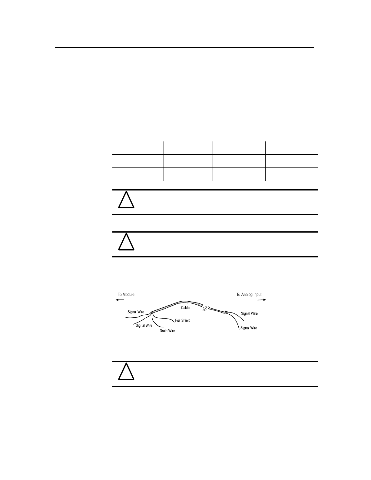
After the module is properly installed, follow the wiring procedure below, using the
proper cable, Belden 8761.
Figure 3-6
To wire your module follow t hese steps.
1. At each end of the cable, strip some casing to expose the individual wires.
2. Trim the signal wires to 2-inch (5 cm) lengths. Strip about 3/16 inch (5 mm) of
insulation away to expose the end of the wire.
!
Attention
Be careful when stripping wires. Wire fragments that fall into a module
could cause damage at power up.
3. At one end of the cable, twist the drain wire and foil shield together, bend them away
from the cable, and apply shrink wrap. Then earth ground at the preferred location
based on the type of sensor you are using. See Grounding for more details.
4. At the other end of the cable, cut the drain wire and foil shield back to the cable and
apply shrink wrap.
Page 28
Compact IO™ Isolated HART Analog Input Module
User's Manual 0300215-03 Rev . A
3-10
5. Connect the signal wires to the terminal block. Connect the other end of the cable to
the analog input device.
6. Repeat steps 1 through 5 for each channel on the module.
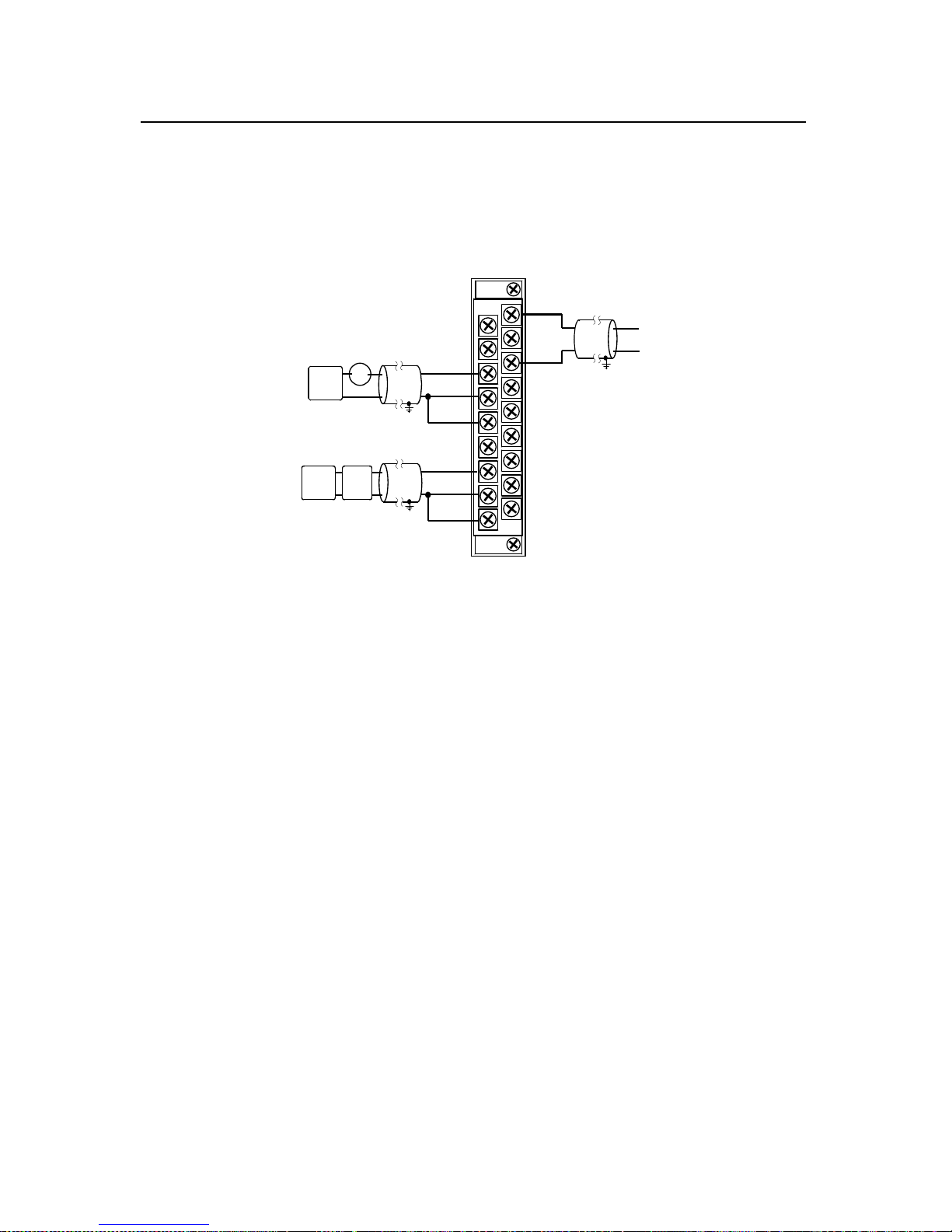
3.7.6 Wiring Diagram
Figure 3-7
N/C
Ch1-iRtn
N/C
Ch3-iRtn
Ch0+
N/C
Ch0-iRtn
Ch0-
Ch1+
N/C
Ch2-iRtn
Ch2-
Ch3+
Ch3-
N/C
N/C
Ch2+
Ch1-
+ -
2 Wire
XMTR
+
-
24V DC
Power
Supply
2 Wire Current Input
+
-
4 Wire Current Input
4 Wire
XMTR
+
+
--
24V DC
Power
Supply
+V
- V
Voltage Input
3.7.7 Calibration
The isolated HART module is initially calibrated at the factory.
Page 29

User's Manual 0300215-03 Rev . A
Chapter 4
Configuring the IF4IH for
CompactLogix Using
RSLogix 5000
This chapter explains how to incorporate the IF4IH module into a CompactLo gix syste m
using RSLogix 5000 programming soft ware. The process of incorporating your HART
module into the CompactLogix system is similar to the process needed to add an AllenBradley module. You will use your RSLogix 5000 programming software to install and
configure your HART module.
An Add-On profile is available on our website to ease the installation of the module, if
you choose not to use the generic module profile. The Add-On profile download also
includes an RSLogix 5000 sample project demonstrating how to read and write H ART
data to and from each channel. The sample project contains user defined data types,
configuration tags, input tags, output tags, and ladder samples needed to configure each
HART module. The topics discussed in this chapter include:
• Setting up the generic profile
• Using the Add-On profile
• Understanding user defined data types
• Adding the controller and program tags
• Using the provided ladder sample
Section 4.1
Setting up the
Generic Profile
The generic profile defines the module for the CompactBus, so that the right number of
input, output and configuration words are reserved. To co nfigure the generic profi le you
can use the profile already created in the sample project, see Figure 4-1, or follow the
procedures outlined below.
Figure 4-1 (Pre-Defined Generic Profile)
Page 30
Compact IO™ Isolated HART Analog Input Module
User's Manual 0300215-03 Rev . A
4-2
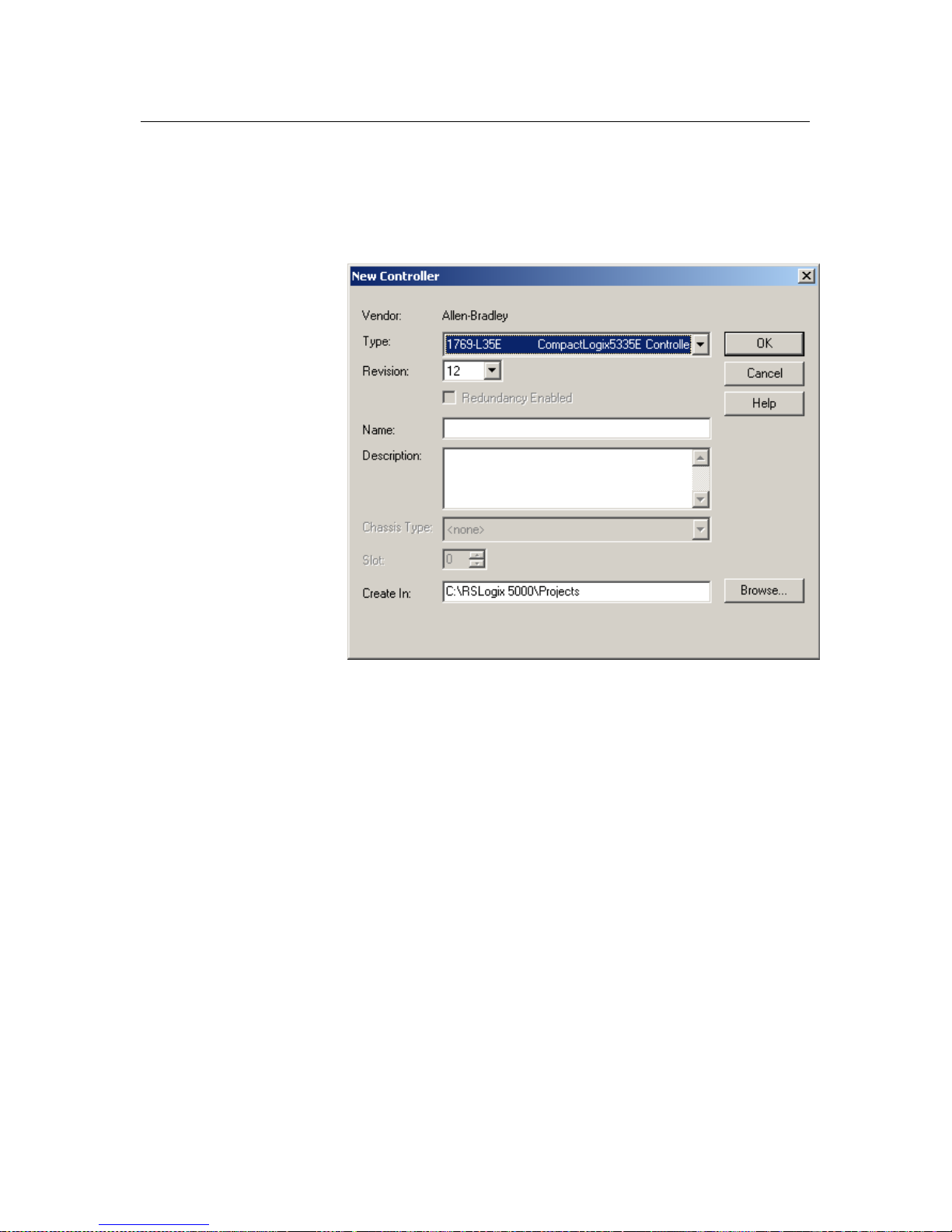
1. Create a new RSLogix 5000 project file. Click on the new project icon or on the
FILE pull-down menu and select NEW. The following screen appears:
Figure 4-2
2. Choose your controller type and enter a name for your project, then click OK.
The following main RSLogix 5000 screen appears:
Page 31

Chapter 4: Configuring the IF4IH for CompactLogix Using RSLogix 5000
User's Manual 0300215-03 Rev . A
4-3
Figure 4-3
3. In the ControllerOrganizer on the left of the screen, right click on
“[0]CompactBus Local”, select New Module, and the following screen appears:
Figure 4-4
Page 32

Compact IO™ Isolated HART Analog Input Module
User's Manual 0300215-03 Rev . A
4-4
4. This screen is used to narrow your search for I/O modules to configure into your
system. With the initial release of the CompactLogix5320 controller, this screen
only includes the “Generic 1769 Module”. Click the OK button and the
following default Generic Profile screen appears:
Figure 4-5
5. First, select the Comm Format (“Data – INT” for the 1769sc-IF4IH), then fill in
the name field. For this example, “IF4IH” is used to help identify the module
type in the Controller Organizer. The Description field is optional and may be
used to provide more details concerning this I/O module in your application.
The slot number must be selected next, although it will begin with the first
available slot number, 1, and increments automatically for each subsequent
Generic Profile you configure. For this example, the 1769sc-IF4IH HART
module is located in slot 1.
The Comm Format, Assembly Instance and Size values are listed in the
following table for the 1769sc-IF4IH HART module:
Table 4-1 (Generic Profile Parameters)
1769 I/O
Module
Comm
Format
Parameter
Assembly
Instance
Size
(16-Bit)
IF4IH Data-INT Input
Output
Config
101
100
102
72
46
34
6. Enter the Assembly Instance numbers and their associated sizes for the 1769scIF4IH module into the Generic Profile. When complete, the Generic Profile for a
1769sc-IF4IH module should look like the following:
Page 33

Chapter 4: Configuring the IF4IH for CompactLogix Using RSLogix 5000
User's Manual 0300215-03 Rev . A
4-5
Figure 4-6
7. At this point you may click “Finish” to complete the configuration of your I/O
module.
Configure each I/O module in this manner. The CompactLogix5320 controller
supports a maximum of 8 I/O modules. The valid slot numbers to select when
configuring I/O modules are 1 through 8.
Section 4.2
Using
The Add-On
Profile
For RSLogix 5000 version 15 and greater an Add-On module profile is available for
download at (http://www.spectrumcontrols.com/downloads.htm
). The Add-On profile
allows the user to add the IF4IH module to the RSLogix 5000 module pick list. The
profile provides configuration and information screens to the user, to simplify
installation. Follow the procedure below to install and use the Add-On pro file.
!
Attention
Module firmware 2.0 and greater is required in order to use the Add-On
profile.
4.2.1 Installing the Add-On profile
1. Download the zipped file from the Spectrum Controls website and unzip the file.
http://www.spectrumcontrols.com/pdfs/abio/SC 1769sc-IF4IH DTM 1.0.0.3 Setup.zip
Page 34

Compact IO™ Isolated HART Analog Input Module
User's Manual 0300215-03 Rev . A
4-6
2. Open the created folder and double-click on the MPSetup.exe file.
3. Follow the online prompts.
4.2.2 Adding the IF4IH Module To Your Logix Project
Once the profiles are installed you can access them through RSLogix 5000 via the I/O
Configuration. Follow the procedure below to add a module:
1. In the I/O Configuration, right mouse click on the 1769 CompactBus and select
“New Module”.
2. When the dialog screen opens, select the “By Vender” tab and expand the
Spectrum Controls folder.
Page 35

Chapter 4: Configuring the IF4IH for CompactLogix Using RSLogix 5000
User's Manual 0300215-03 Rev . A
4-7
3. Highlight the module and press the “OK” button.
4. Configure the module using the custom configuration screens.
Note: The 1769sc-IF4IH still requires ladder to demultiplex the HART data and send
HART messages via the controller. Please refer to the sample project packaged with
the profile install for more information.
Section 4.3
User Defined
Data Types
The sample project contains user defined data types which define the structure for tags
used within the project. The data types organize the HART data returned by the module
and are referenced throughout this manual, so it is highly recommended that these data
types be used whenever possible.
Select the data type you wish to copy from the Controller Organizer and past it into your
project under user defined data types. See figure below.
Figure 4-7 (Copying Data Types)
!
Attention
The user defined data types should be copied before copying the tags or
ladder.
Drag and
drop one at a
time
Sample
Project
Your
Project
Page 36

Compact IO™ Isolated HART Analog Input Module
User's Manual 0300215-03 Rev . A
4-8
The table below gives a brief description of each data type.
Table 4-2 (User Defined Data Type Descriptions)
User Defined Data Type Description
GetDeviceInfoStructure Defines the structure of the HART data returned by the
module when the module specific command, Get
Device Information, is sent to module.
1
If4ihMessage This data type defines the structure for tags used to
send messages to and from the module using the paging
scheme.
1
If4ihPassThruMsg Defines the structure for tags used to send HART pass
through messages to and from the module.
1
Packet0 Defines the data structure for HART packet 0. HART
packet zero contains device information for the
connected HART device.
1
Packet1 Defines the data structure for HART packet 1. HART
packet 1 is used to display the four dynamic variables
for the selected HART device.
1
Packet2 Defines the data structure for HART packet 2. HART
packet 2 is used to display the slot variables for the
connected HART device.
1
Packet3 Defines the data structure for HART packet 3. HART
packet 3 displays the ASCII message for the connected
HART device.
1
Packet4 Defines the data structure for HART packet 4. HART
packet 4 contains the extended status for the connected
HART device.
1
Section 4.4
Project Tags
The project tags were created to simplify the configuration of the module. Some of the
tags defined in the sample project utilize the user defined data types described in the
previous section.
The user defined tags from the controller scope should be copied to your project before
the tags contained in the individual program sections. Open the controller tags on the
sample project and select the edit tags mode. Grab the t ags you want to copy by using
the left mouse button and dragging. See figure below.
1
Refer to Chapter 6 for more details.
2
Refer to Chapter 7 for more details.
Page 37

Chapter 4: Configuring the IF4IH for CompactLogix Using RSLogix 5000
User's Manual 0300215-03 Rev . A
4-9
Figure 4-8 (Copying Controller Tags)
After copying the controller tags you can copy the program tags next. Follow the same
procedure shown in Figure 4-8.
Section 4.5
Sample Project
Ladder
The ladder contained in the sample project is used to perform se veral different operations.
The main routine in the MainProgram is used to jump to the routines that copy the
multiplexed HART data from the module.
The If4ih0_Packet_Data routine in the MainProgram contains the ladder that
demultiplexes the HART data for each individual packet. Refer to Chapter 7 for more
information on HART and the HART packets.
The If4ih0Messaging program contains several routines needed to send and receive
HART messages to and from the module and the connected HART devices.
To copy any of the ladder, programs or routines, follow the procedure below:
1. Select the program or routine.
2. Right mouse click and select copy.
3. Go to your project and select the appropriate program or task to place the new
routine or program.
4. Right mouse click and select paste.
Sample
Project
Your
Project
Copy and
paste tags
Page 38

Compact IO™ Isolated HART Analog Input Module
User's Manual 0300215-03 Rev . A
4-10
The figure below outlines this procedure:
Figure 4-9 (Copying Routines or Programs)
You can follow a similar procedure for copying ladder as well.
1. Open the routine that contains the ladder you want to copy.
2. Select the rungs to copy.
3. Right mouse click and select copy.
4. Open the routine in your project where you wish to paste the new rungs.
5. Right mouse click and select paste.
The figure below demonstrates this procedure:
Sample
Project
Your
Project
Copy
and
p
aste
Page 39

Chapter 4: Configuring the IF4IH for CompactLogix Using RSLogix 5000
User's Manual 0300215-03 Rev . A
4-11
Figure 4-10 (Copying Ladder)
Sample
Project
Your
Project
Page 40

Compact IO™ Isolated HART Analog Input Module
User's Manual 0300215-03 Rev . A
4-12
Page 41

User's Manual 0300215-03 Rev . A
Chapter 5
Configuring the IF4IH for a
MicroLogix 1500 Using
RSLogix 500
This chapter examines the 1769sc-IF4IH module’s addressing scheme and describes
module configuration using RSLogix 500 and a MicroLogix 1500 controller. This
chapter will cover the following:
• Module Addressing
• Configuring the IF4IH in a MicroLogix 1500 System
• Using the Ladder Sample
Section 5.1
Module
Addressing
The following memory map shows the input, output, and configuration image tables for
the module. Detailed information on the image table is located in Chapter 6.
Figure 5-1 (Module Memory Map)
slot e
Input Image File
Input Image
72 Words
Memory Map
Word 0: Channel 0 Data Word
Word 1: Channel 1 Data Word
Word 2: Channel 2 Data Word
Word 3: Channel 3 Data Word
Word 4: Time Stamp Value
Word 5: General Channel Status
Word 6: Process & Range Alarms
Word 7: Pad
Words 8..27: HART Packet Data
Word 28: ScanMSG Slave Control
Word 29: ScanMSG Response Size
Words 30..49: ScanMSG Response Buffer
Bit 15
Bit 1
slot e
Configuration File
Configuration
34 Words
Words 2..7: Channel 0 Configuration
Words 8..13: Channel 1 Configuration
Words 14..19: Channel 2 Configuration
Words 20..25: Channel 3 Configuration
Bit 15
Bit 1
Word 1: Module Configuration
Word 0: Real Time Sample
slot e
Output File
Output
46 Words
Word 2: ScanMSG Master Control
Word 3: ScanMSG Request Size
Word 4..23: ScanMSG Request Buffer
Bit 15
Bit 1
Word 1: Last Packet Scanned
Word 0: Unlatch Alarms/HART Suspend
Word 26: Ch0 Slot Variables 0 & 1
Word 27: Ch0 Slot Variables 2 & 3
Word 28: Ch1 Slot Variables 0 & 1
Word 29: Ch1 Slot Variables 2 & 3
Word 30: Ch2 Slot Variables 0 & 1
Word 31: Ch2 Slot Variables 2 & 3
Word 32: Ch3 Slot Variables 0 & 1
Word 33: Ch3 Slot Variables 2 & 3
Words 50..71: Reserved
Word 24..45: Reserved
Page 42

Compact IO™ Isolated HART Analog Input Module
User's Manual 0300215-03 Rev . A
5-2
For example, to obtain the general status for channel 2 of the module located in slot e, use
address I:e.5/2.
Figure 5-2 (Address Example)
Slot
Word
Bit
Input File Type
Element
Delimiter
Word
Delimiter
Bit
Delimiter
I:e.5/2
NOTE: The end cap does not use a slot address.
Section 5.2
Configuring
the 1769sc-IF4IH
in a MicroLogix
1500 System
This example takes you through configuring your 1769scIF4IH isolated HART analog
input module with RSLogix 500 programming so ftware, assumes your module i s
installed as expansion I/O in a MicroLogix 1500 system, and that RSLinx™ is properly
configured and a communications link has been established between the MicroLogix
processor and RSLogix 500.
!
Attention
It is recommended that a 1764-LRP series C processor with firm ware
version 5 or higher be used. The LRP processor supports floating point files,
which is required to read floating point data from the IF4IH.
Start RSLogix and create a MicroLogix 1500 application. The following screen appears:
Page 43

Chapter 5: Configuring the IF4IH for A MicroLogix 1500 Using RSLogix 500
User's Manual 0300215-03 Rev . A
5-3
Figure 5-3
While offline, double-click on the IO Configuration icon under the controller folder and
the following IO Configuration screen appears.
Figure 5-4
This screen allows you to manually enter expansion modules into expansion slots, or to
automatically read the configuration of the controller. To read the existing controller
configuration, click on the Read IO Config button.
A communications dialog appears, identifying the current communications confi g uration
so that you can verify the target controller. If the communication settings are correct,
click on Read IO Config.
Page 44

Compact IO™ Isolated HART Analog Input Module
User's Manual 0300215-03 Rev . A
5-4
Figure 5-5
The actual I/O configuration is displayed. In this example, a second tier of I/O is attached
to the MicroLogix 1500 processor.
Figure 5-6
The 1769sc-IF4IH module is installed in slot 1. To configure the module, double-click on
the module/slot. The general configuration screen appears.
Page 45

Chapter 5: Configuring the IF4IH for A MicroLogix 1500 Using RSLogix 500
User's Manual 0300215-03 Rev . A
5-5
Figure 5-7
!
Attention
When using the read IO configuration feature in RS Lo gix, you need to
manually enter 34 into the “extra data length” field.
To configure the module select the Generic Extra Data Configuration tab. Enter the
decimal equivalent of each configuration word. There are a total of thirty four words that
need to be configured altogether. The module default settings are used if all the
configuration words are left at zero.
Figure 5-8
NOTE: For a complete description of each of these parameters and the choices
available for each of them, refer to Chapter 6.
Page 46

Compact IO™ Isolated HART Analog Input Module
User's Manual 0300215-03 Rev . A
5-6
Section 5.3
Using the
Ladder Sample
To get started we recommend that you use the provided MicroLogix 1500 sample project.
Refer to Chapter 8 for the sample project or visit our website at
(www.spectrumcontrols.com
).
The sample project contains nine different subroutines which are used to perform various
HART related tasks. The following list describes the function of each subroutine within
the project file.
Table 5-1 (Ladder Routines)
Routine Description
MAIN
The main routine is the starting point for the ladder
program.
PACKETS
The “packets” routine is used to demultiplex the HART
data from the input file to individual integer files, so that
the data can be viewed or used within the ladder program.
This routine is called from the MAIN routine.
MSG_TO_MOD
This routine is used to send and receive messages to and
from the module. Refer to Chapter 7 for more details
regarding sending and receiving messages. This routine is
called from the HART_MSG routine.
SRC_CHECK
Calculates the checksum for a message sent to the module
one page at a time. This routine is called from the
MSG_TO_MOD routine.
DEST_CHECKSUM
This routine calculates the checksum for a message
received from the module one page at a time. This routine
is called from the MSG_TO_MOD routine.
HART_MSG
This routine composes HART messages that will be sent to
the module/field transmitter. This routine is called from
the MAIN routine.
WORD_BYTE
Converts word data to its byte equivalent. This routine is
called from the HART_MSG routine.
HART_CHECK
Calculates the checksum for the HART message being sent
to the module/field device. This routine is called from the
HART_MSG routine.
BYTE_WORD
Converts byte data to its word equivalent. This routine is
called by the HART_MSG routine.
You have the choice to either use the sample project or copy and past the pieces you need
from the project.
5.3.1 Copying Subroutines from the Sample Project
To copy subroutines from the sample project to your project, fo llow the steps below:
1. Open the sample project and your project.
2. Select the subroutine you wish to co py.
3. Right mouse click and select copy.
4. Go to your project and select where you would like to place the new routine.
Page 47

Chapter 5: Configuring the IF4IH for A MicroLogix 1500 Using RSLogix 500
User's Manual 0300215-03 Rev . A
5-7
5. Right mouse click and select paste.
Figure 5-9 (Copying Routines)
5.3.2 Copying Ladder from the Sample Project
To copy ladder, follow the procedure below:
1. Open the sample project and your project
2. Open the routine that you wish to copy the ladder from.
3. Select the rungs by clicking the left mouse button. To select more rungs, select
the first rung you wish to copy and while holding the shift key, select the last
rung you wish to copy.
4. Right mouse click and select copy.
5. Open the routine in your project where you wish to place the new rungs.
6. Select the paste point by left mouse clicking.
7. Right mouse click and select paste.
Copy
and
p
aste
Sample
Pro
ject
Your
Pro
ject
Page 48

Compact IO™ Isolated HART Analog Input Module
User's Manual 0300215-03 Rev . A
5-8
Figure 5-10 (Copying Ladder)
5.3.3 Importing Tag Database and Rung Comments
After copying the subroutines and or the ladder, you may wish to import the tags and
rung comments. Follow the procedure below to import the tag database and rung
comments:
1. Open the sample project and your project.
2. In the sample project, go to the tools menu, select database, and then select
ASCII export. See image below:
Copy
and
p
aste
Sample
Pro
j
ect
Your
Pro
j
ect
Page 49

Chapter 5: Configuring the IF4IH for A MicroLogix 1500 Using RSLogix 500
User's Manual 0300215-03 Rev . A
5-9
3. After selecting ASCII export the following screen appears:
4. Select the RSLogix 500 tab and press the OK button.
5. Select the location for the export file.
6. In your project, go to the tools menu, select database, and select ASCII import.
See image below:
Page 50

Compact IO™ Isolated HART Analog Input Module
User's Manual 0300215-03 Rev . A
5-10
7. After selecting ASCII import the following screen should appear:
8. Select the RSLogix 500 radio button and leave everything else at default. After
making your selections, press the OK button.
9. Select the export file from steps 4 and 5 and press the open button. You may be
prompted for multiple files depending on the selections you made in step 8.
Page 51

User's Manual 0300215-03 Rev . A
Chapter 6
Module Data, Status, and
Channel Configuration
After installing the 1769sc-IF4IH isolated HART input module, you must configure it for
operation, usually using the programming software compatible with the controller (for
example, RSLogix 500 or RSLogix 5000). Once confi guration is complete and reflected
in the ladder logic, you need to operate the module and verify its config uration.
This chapter contains information on the following:
• Modu l e memory ma p
• Accessing input image file data ·
• Configuring channels
• Determining effective resolution and range
• Determining module update time
Section 6.1
Module Memory
Map
The module uses fifty input words for data and status bits (input image), twenty four
output words, and thirty four configuration word s.
Figure 6-1 (Module Memory Map)
NOTE: Not all
controllers support
program access to the
configuration file. Refer
to your controller’s user
manual.
slot e
Input Image File
Input Image
72 Words
Memory Map
Word 0: Channel 0 Data Word
Word 1: Channel 1 Data Word
Word 2: Channel 2 Data Word
Word 3: Channel 3 Data Word
Word 4: Time Stamp Value
Word 5: General Ch annel Status
Word 6: Process & R ange Alarms
Word 7: Pad
Words 8..27: HART Packet Data
Word 28: ScanMSG Slave Contro l
Word 29: ScanMSG Response Size
Words 30..49: ScanM SG Response Buffer
Bit 15
Bit 1
slot e
Configuration File
Configuration
34 Words
Words 2..7: Channel 0 Configura tion
Words 8..13: Channel 1 Configuration
Words 14..19: Channel 2 Configur ation
Words 20..25: Channel 3 Configur ation
Bit 15
Bit 1
Word 1: Module Configuration
Word 0: Real Time Sample
slot e
Output File
Output
46 Words
Word 2: ScanMSG Master Control
Word 3: ScanMSG Request Size
Word 4..23: ScanMSG Request Buffer
Bit 15
Bit 1
Word 1: Last Packet Scanned
Word 0: U nlatch Alarms/HART Suspend
Word 26: Ch0 Slot Variables 0 & 1
Word 27: Ch0 Slot Variables 2 & 3
Word 28: Ch1 Slot Variables 0 & 1
Word 29: Ch1 Slot Variables 2 & 3
Word 30: Ch2 Slot Variables 0 & 1
Word 31: Ch2 Slot Variables 2 & 3
Word 32: Ch3 Slot Variables 0 & 1
Word 33: Ch3 Slot Variables 2 & 3
Words 50..71: Reserved
Word 24..45: Reserved
Page 52

Compact IO™ Isolated HART Analog Input Module
User's Manual 0300215-03 Rev . A
6-2
Section 6.2
Accessing Input
Image File Data
The input image file represents data words and status words. Input words 0 through 3
hold the input data that represents the value of the analog inputs for channels 0 through 3.
These data words are valid only when the channel is enabled and there are no errors.
Input word 4 contains the time stamp value. Words 5 and 6 contain status information
for the four channels including process alarms and over and under range flags. Word 7
contains the HART channel identification and status information. Words 8 through 27
include the HART packet data. Refer to Chapter 7 for information on how to demultiplex
the HART packet data. Input word 28 holds the message control. Word 29 holds the
message response size. Words 30 through 49 hold the message response buffer. Refer to
Chapter 7 for more information regarding input words 28 through 49.
You can access the information in the input image file using the programming software
configuration screen. For information on configuring the module in a MicroLogix 1500
system using RSLogix 500, see Chapter 5; and for the CompactLogix using RSLogix
5000, see Chapter 4.
Section 6.3
Input Data File
The input data file allows you to access module input data for use in the control program,
via word and bit access. The data table structure is shown in the table below.
Table 6-1 (Module Input Imag e )
Word/Bit¹15 14 13 12 11 10 9 8 7 6 5 4 3 2 1 0
0
1
2
3
4
5 OS3 OS2 OS1 OS0 S3 S2 S1 S0
6 L3H3U3O3L2H2U2O2L1H1U1O1L0H0U0O0
7
8..27
28
29
30..49
50..71
(1) Ch anging bit values is not supported by all controllers . Refe r to your controller manual for details.
Reserved
Time S tamp Value
Messag e Re sponse Size
Not Used
Pad (1 6 bi t a lignment)
Message Re sponse Buffer
Analog Input Data Cha nnel 0
Analog Input Data Cha nnel 1
Analog Input Data Cha nnel 2
A
nalog Input Data Channel 3
HART Pa cket Data
Messa
g
e Slave Control
6.3.1 Input Data Values (Words 0 to 3)
Data words 0 through 3 correspond to channels 0 through 3 and contain the converted
analog input data from the input device. The most significant bit, bit 15, is the sign bit
(SGN).
6.3.2 Time Stamp Value (Word 4)
The time stamp value represents the instant in time that the current input data was read.
The time stamp value is measured in milliseconds from 0 to 32767. When the value
reaches 32767, the timer will roll over to 0 and then the process will repeat.
6.3.3 General Status Bits S0 to S3 (Word 5)
Bits S0 through S3 of word 5 contain the general status information for channels 0
through 3, respectively. If set (1), this bit indicates an error (over- or under-range, low or
high alarm, or channel data not valid). The data not valid condition is described below.
Page 53

Chapter 4: Module Data, Status, and Configuration
User's Manual 0300215-03 Rev . A
6-3
Input Data Not Valid Condition
The general status bits S0 to S3 also indicate whether or not the input data for a particular
channel, 0 through 3, is being properly converted (valid) by the module. This “invalid
data” condition can occur (bit set) when the download of a new configuration to a
channel is accepted by the module (proper configuration) but before the A/D converter
can provide valid (properly configured) data to the 1769 bus master/controller. The
following information highlights the bit operation of the Data Not Valid condition.
1. The default and module power-up bit condition is reset (0).
2. The bit condition is set (1) when a new configuration is received and determined
valid by the module. The set (1) bit condition remains until the module begins
converting analog data for the previously accepted new configuration. When
conversion begins, the bit condition is reset (0). The amount of time it takes for the
module to begin the conversion process depends on the number of channels being
configured and the amount of configuration data downloaded by the controller.
NOTE: If the new configuration is invalid, the bit functio n remains reset (0) and the
module posts a configuration error. See Configuration Errors on page 9-4.
3. If A/D hardware errors prevent the conversion process from taking place, the bit
condition is set (1).
6.3.4 Out of Service Status Bits OS0 to OS3 (Word 5)
Bits SO0 through SO3 of word 0 indicate whether the associated channel is out of service
(i.e. automatic HART acquisition is suspended).
Note: A channel that is placed out-of-service (i.e. Suspended) will automatically
resume service after three minutes, as long a s no pass-through commands are issued
before the three minutes expires.
6.3.5 Over-Range Flag Bits O0 to O3 (Word 6)
Over-range bits for channels 0 through 3 are contained i n word 6, even-numbered bits.
They apply to all input types. When set (1), the over-range flag bit indicates an input
signal that is at the maximum of its normal operating range for the represented channel or
sensor. The module automatically resets (0) the bit when the data value falls below the
maximum for that range.
Note: If a channel is configured for a voltage type input and an open-circuit co ndition
is present, the over-range flag bit will be set to indicate the open circuit condition and
the associated channel data word will disp lay the full-scale value.
6.3.6 Under-Range Flag Bits U0 to U3 (Word 6)
Under-range bits for channels 0 through 3 are contained in word 6, odd-numbered bits.
They apply to all input types. When set (1), the under-range flag bit indicates an input
signal that is at the minimum of its normal operating range for the represented channel or
sensor. The module automatically resets (0) the bit when the under-range condition is
cleared and the data value is within the normal operating range.
Note: If a channel is configured for a current type input and an open-circuit condition
is present, the under-range flag bit will be set to indicate the o pen circuit condition and
the associated channel data word will display the minimum scale value.
6.3.7 High Process Alarm Flag Bits H0 to H3 (Word 6)
The high process alarm flag is set when the measured analog signal exceeds the high
process alarm setpoint. The high process alarm setpoint is defined in Section 6.4 Module
Configuration.
Page 54

Compact IO™ Isolated HART Analog Input Module
User's Manual 0300215-03 Rev . A
6-4
6.3.8 Low Process Alarm Flag Bits L0 to L3 (Word 6)
The low process alarm flag is set when the measured analog signal falls below the low
process alarm setpoint. The low process alarm setpoint is defined in Section 6.4 Module
Configuration.
6.3.9 Pad (Word 7)
Word 7 is not used and will always be zero. This word is used to maintain 16 bit
alignment.
6.3.10 HART Data (Words 8 to 27)
This block of twenty words contains the multiplexed HART data for all four channels.
1
6.3.11 Message Slave Control (Word 28)
The message slave control word controls how data is returned from the mo dule after
sending a mess age using output words 2 through 23
1
.
6.3.12 Message Reply Size (Word 29)
The message reply size indicates the number of bytes returned by the module after
sending a mess age using output words 2 through 23
1
.
6.3.13 Message Reply Buffer (Words 30…49)
After sending a message to the module, the response data for the messa ge is stored in the
message reply buffer
1
.
6.3.14 Reserved (Words 50…71)
Reserved for future expansion.
1
For more details refer to Chapter 7
Page 55

Chapter 4: Module Data, Status, and Configuration
User's Manual 0300215-03 Rev . A
6-5
Section 6.4
Module
Configuration
After module installation, you must configure operation details, such as input type, data
format, etc., for each channel. Configuration data for the module is stored in t he
controller configuration file, which is both readable and writable.
The default value of the configuration data is represented by zeros in the data file. The
structure of the channel configuration file is shown below.
Table 6-2a (Module Configuration)
15 14 13 12 11 10 9 8 7 6 5 4
3
210
0
Real Time Sample
1
ETS 0 EH3EH2EH1EH0
Ge ner a l Co nf igu r at io n
Bits
2
EC EA AL EI
Ch0 Filter Frequency and
Gener al Settings
3
Ch0 Data forma t and
inp ut type
4
Ch 0 Process Alarm High
Value
5
Ch0 Process Al arm Low
Value
6
Ch0 Alarm Deadband
7
Data Padding
8
EC EA AL EI
Ch1 Filter Frequency and
Gener al Settings
9
Ch1 Data forma t and
inp ut type
10
Ch 1 Process Alarm High
Value
11
Ch1 Process Al arm Low
Value
12
Ch1 Alarm Deadband
13
Data Padding
14
EC EA AL EI
Ch2 Filter Frequency and
Gener al Settings
15
Ch2 Data forma t and
inp ut type
16
Ch 2 Process Alarm High
Value
17
Ch2 Process Al arm Low
Value
18
Ch2 Alarm Deadband
19
Data Padding
20
EC EA AL EI
Ch3 Filter Frequency and
Gener al Settings
21
Ch3 Data forma t and
inp ut type
22
Ch 3 Process Alarm High
Value
23
Ch3 Process Al arm Low
Value
24
Ch3 Alarm Deadband
25
Data Padding
Function
Real Ti me Sample Value
Reserved Slot Variable ( 0-3) Input Filter Ch3
Reserved
Ch3 Data
Reser v ed Ch3 Inpu t Type
PA
Reserved Slot Variable (0-3) Input Filter Ch 0
Handle Timeout
Word
Bit
Ch1 Input Type
Pad
Channel 0 High Pr ocess Alarm Setpoint
Channel 0 Low Process Alarm Setpoint
Channel 0 Alarm Deadband
Reserved
Ch0 Data
Reser v ed Ch0 Inpu t Type
Pad
Channel 1 High Pr ocess Alarm Setpoint
Channel 1 Lo w Proc ess Alarm Setpoint
Channel 1 Alarm Deadband
Reserved Slot Variable (0-3) Input Filter Ch 1
Reserved
Ch1 Data
Reserve d
Channel 2 High Pr ocess Alarm Setpoint
Channel 2 Lo w Proc ess Alarm Setpoint
Channel 2 Alarm Deadband
Reserved Slot Variable (0-3) Input Filter Ch 2
Reserved
Ch2 Data
Reser v ed Ch2 Inpu t Type
Pad
Pad
Channel 3 High Pr ocess Alarm Setpoint
Channel 3 Lo w Proc ess Alarm Setpoint
Channel 3 Alarm Deadband
Page 56

Compact IO™ Isolated HART Analog Input Module
User's Manual 0300215-03 Rev . A
6-6
Table 6-2b (Module Configuration)
1514 13 12 11 10 9 8 7 6
5
43210
26
Defines Slot
Variables
27
Defines Slot
Variables
28
Defines Slot
Variables
29
Defines Slot
Variables
30
Defines Slot
Variables
31
Defines Slot
Variables
32
Defines Slot
Variables
33
Defines Slot
Variables
Channel 3 HART Slot Variables 2 & 3
Channel 1 HART Slot Variables 2 & 3
Channel 2 HART Slot Variables 0 & 1
Channel 2 HART Slot Variables 2 & 3
Channel 3 HART Slot Variables 0 & 1
Word
Bit
Function
Channel 0 HART Slot Variables 2 & 3
Channel 0 HART Slot Variables 0 & 1
Channel 1 HART Slot Variables 0 & 1
6.4.1 Real Time Sample Value (Word 0)
The real time sample value determines when the module will scan its input channels for
available data. After the channels are scanned, the data is made available to the PLC.
The valid range for the real time sample is 0
1
to 5000 ms (i.e. Enter a value of 0 to 5000).
Note: The Real Time Sample rate must be greater than or equal to the slowest channel
step response time. See Table 6-5 to determine the proper RTS rate.
Note: The configuration file can also be modified throug h the control program, if
supported by the controller. For information on configuring the module using
RSLogix 500 (with MicroLogix 1500 controller), see Chapter 5; for RSLogix 5000
(CompactLogix controller), see Chapter 4.
6.4.2 General Configuration Bits (Word 1)
Word 1 is used to configure general module properties like enabling and disabling
HART, setting a HART handle time for HART messaging, and selecting one of three
scanning schemes for HART pass-through messages. The table below shows the
available settings for word 1.
Table 6-3 (General Configuration Bits)
1514 13121110987654
3
210
Disable
0
Enabl ed
1
Disable
0
Enabl ed
1
Disable
0
Enabl ed
1
Disable
0
Enabl ed
1
Pass-Through Scheme
Two Ch an nel Sc an s 0 0
Once P er Module Scan
01
Every Ch annel Scan 1 0
Reserved
Set to Zero 0
ETS
Disabled
0
Enabled
1
Make the se bit setti n gs
Han dle Timeo ut (1 to 255 sec)
CH0 HART Enable
CH1 HART Enable
CH2 HART Enable
CH3 HART Enable
To Select
Handle Timeout
1
When RTS is set to zero, all channels are acquired freely and independently with no idle time. A channel
configured at a high filter frequency can be acquired multiple times in the time that a single acquisition is made for a
channel configured at a lower filter frequency.
Page 57

Chapter 4: Module Data, Status, and Configuration
User's Manual 0300215-03 Rev . A
6-7
NOTE Default settings for a particular function are indicated by zero(s). For example,
the default filter frequency is 60Hz. Publication
Handle Timeout
There is a handle timeout associated with the final reply message. After the module
obtains the requested information from the HART device, it will start the Handle Timeout
timer. The reply message will be kept in memory during the Handle Timeout period.
After the timeout occurs or after the message is retrieved by the pass -through response
query command, the storage buffer will be discarded, and another pass through message
will be serviced without being rejected. Handle Timeout is in the range of 0 to 255
seconds.
Note: A handle timeout of zero is valid. When set to zero t he handle timeout will
default to 10 seconds.
Channel HART Enable (Bits 8, 9, 10, 11)
These bits allow the user to enable HART on channels 0 through 3, respectively.
Pass-Through Scheme
The pass-thro ugh scheme determines how ofte n a pass through command is serviced.
• Two Channel Scans: Pass-through serviced once every two channel scans
• Once Per Module Scan: Pass-through serviced once per module scan
• Every Channel Scan: Pass-through serviced once every channel scan
Note: The pass-through scheme can increase the HART packet update time if passthrough messages are serviced every channel scan. Refer to Chapter 7 for more
details.
ETS (Enable Time Stamp)
Allows module time stamping function to be enabled. See section 6.3.2 for more details.
6.4.3 Filter Frequency and General Settings (Words 2, 8, 14, 20)
This section of the configuration allows the user to configure filter frequencies, enable or
disable the associated channel, etc.
Page 58

Compact IO™ Isolated HART Analog Input Module
User's Manual 0300215-03 Rev . A
6-8
Table 6-4 (Filter Frequency and General Settings)
15 14 13121110987654321
0
60 H z 0
000
50 Hz 0
0
0
1
28.5 Hz 0
010
300 Hz 0
0
11
360 Hz 0100
Disable 0
Enable 1
Disable 0
Enable 1
Disable 0
Enable 1
Disable 0
Enable 1
Disable 0
Enable 1
Disable 0
Enable 1
Disable
0
Enable 1
Reserved
Set To Zero 0000
Disable 0
Enable 1
EI (Enable Interrupt)
AL (Alarm La tch)
EA (Enable Al arm)
To Select
Make these bit setti n gs
EC (Enable Channel)
Slot Code 0
Slot Code 1
Slot Code 2
Slot Code 3
Filter Frequenc y
Input Filter Selection (Bits 0 through 3)
Each channel can be configured for five different filter settings. Select one of the five
filters, for the associated channel.
Effects of Filter Frequency on Noise Rejection
The filter frequency that you choose for a module channel determines the amount of
noise rejection for the inputs. A lower frequency (50 Hz versus 300 Hz) provides better
noise rejection and increases effective resolution, but also increases channel update time.
A higher filter frequency provides lower noise rejection, but decreases the channel update
time and effective resolution.
When selecting a filter frequency, be sure to consider cut-off frequency and channel step
response to obtain acceptable noise rejection. Choose a filter frequency so that your
fastest-changing signal is below that of the filter’s cut-off frequency.
Common Mode Rejection is better than 60 dB at 50 and 60 Hz, with the 50 and 60 Hz
filters selected, respectively, or with the 28.5Hz filter selected. The module performs well
in the presence of common mode noise as long as the signals applied to the user positive
and negative input terminals do not exceed the common mode voltage rating (±500V) of
the module. Improper earth ground may be a source of common mode noise.
NOTE: Transducer power supply noise, transducer circuit noise, or process variable
irregularities may also be sources of normal mode noise.
Effects of Filter Frequency on Channel Step Respon se
The selected channel filter frequency determines the channel’s step response. The step
response is the time required for the analog input signal to reach 100% of its expected
final value, given a full-scale step change in the input signal. This means that if an input
signal changes faster than the channel step response, a portion of that signal will be
attenuated by the channel filter. The channel step response is calculated by a settling time
of 3 x (1/filter frequency).
!
Attention
The Real Time Sample rate must be greater than or equal to the slowest
channel step response time or a configuration error will occur.
Page 59

Chapter 4: Module Data, Status, and Configuration
User's Manual 0300215-03 Rev . A
6-9
Table 6-5 (Filter Frequency and Step Response)
Fil te r Frequency
Step Response
1
28 .5 Hz 10 8 ms
50 Hz 62 ms
60 Hz
52 ms
300 Hz
12 ms
360 Hz
10 ms
1
The c hann el update time is equ al to the channel step respose.
Channel Cut-Off Frequency
The filter cut-off frequency, -3 dB, is the point on the frequency response curve where
frequency components of the input signal are passed with 3 dB of attenuation. The
following table shows cut-off frequencies for the supported filters.
Table 6-6 (Filter Frequency versus Channel Cut-off Frequency)
Filte r FrequencyCut -off FrequencyRejection
28 .5 Hz
2. 3 H z 67 db @ 50/60 H z
50 Hz 4.0 Hz 96 db @ 50 Hz
60 Hz 4.7 Hz 96 db @ 60 Hz
300 Hz
24 Hz
25 db @ 50 Hz
360 Hz 28 Hz 25 db @ 60 Hz
All input frequency components at or below the cut-off fr equency are passed by the
digital filter with less than 3 dB of attenuation. All frequency components above the cutoff frequency are increasingly attenuated as shown i n Figure 6-2 (Frequency Response).
Page 60

Compact IO™ Isolated HART Analog Input Module
User's Manual 0300215-03 Rev . A
6-10
Figure 6-2 (Frequency Response)
The cut-off frequency for each channel is defined by its filter frequency selection. Choose
a filter frequency so that your fastest changing signal is below that of the filter’s cut-off
frequency. The cut-off frequency should not be confused with the update time. The cutoff frequency relates to how the digital filter attenuates frequency components of the
input signal.
The update time defines the rate at which an input channel is scanned and its channel data
word is updated.
28.5Hz Filter
-120
-100
-80
-60
-40
-20
0
0102030405060708090
Filter Rejection (dB)
50 Hz Filter
-120
-100
-80
-60
-40
-20
0
0 20 40 60 80 100 120 140 160
Filter Rejection (dB)
60Hz Filter Oper ation
-120
-100
-80
-60
-40
-20
0
0 50 100 150 200
Filter Rejection (dB)
300Hz Filter Ope ration
-120
-100
-80
-60
-40
-20
0
0 200 400 600 800 1000
Filter Re jection (dB)
360Hz Filter Ope ration
-120
-100
-80
-60
-40
-20
0
0 200 400 600 800 1000 1200
Filter Rejection (dB)
Page 61

Chapter 4: Module Data, Status, and Configuration
User's Manual 0300215-03 Rev . A
6-11
Slot Variable Enable (Bits 4 through 7)
Slot variable enable bits 4 through 7 can be used to enable HART slot variables 0 through
3, respectively, for the connected HART device. The variable code which is used to
define each slot variable for each associated channel is entered into configuration words
26 through 33. Refer to section 6.4 .9 for more information regarding configuri ng slot
variables.
Note: Slot variables are not supported by all HART devices.
Note: Slot codes must be enabled in sequential order. For example, SV0 (Enabled),
SV1 (Disabled), and SV2 (Enabled), is not a valid configuration. In this case, all three
slot variables would be enabled.
EI (Enable Interrupt)
Allows each channel’s process alarm interrupts to be enabled.
AL (Alarm Latch)
Allows latching of each channel’s process alarms to be enabled.
EA (Enable Alarm)
Enable process alarming on the associated channel.
Reserved
Reserved for future expansion and should be set to zero.
EC (Enable Channel)
Enable associated channel.
6.4.4 Input Type and Data Format (Words 3, 9, 15, 21)
This section of the configuration allows the user to define the input type (i.e. 0 to 20mA,
4 to 20 mA, 0 to 10VDC, etc) and the data format for the associated channel.
Table 6-7 (Input Type and Data Format)
15 14 13 12 11 10 9 8 7
654
3210
-10 to +10V
0000
0 to 5V
0001
0 to 10V
0010
4 to 20mA
0011
1 to 5V
0100
0 to 20mA
0101
Reserved
S et To Ze ro
0000
Raw/Prop ortional
000
En gi ne er i ng U ni t s
001
Scaled for PID
010
Perc e nt Rang e
011
Reserved
S et To Ze ro
00000
To Select
Make these bit setting s
Input Type
Data Type
Input Type
Allows the user to configure the input type and range for the associated channel.
Note: To enable HART you must select the 4 to 20 mA range.
Page 62

Compact IO™ Isolated HART Analog Input Module
User's Manual 0300215-03 Rev . A
6-12
Reserved
Reserved for future expansion and should be set to zero.
Data Format
This selection allows the associated channel to present analog data in any of the
followin g fo rmats:
•
Raw/Proportional Data
The value presented to the controller is proportional to the selected input and
scaled into the maximum data range allowed by the bit resolution of the A/D
converter and filter selected. The raw/proportional data format also provides the
best resolution of all the data formats.
If you select the raw/proportional data format for a channel, the data wo rd will
be a number between -32767 and +32767. For example, if a 4 to 20 mA input
type is selected, 4 mA corresponds to -32767 counts and 20 mA corresponds to
+32767. See Determining
Effective
Resolution
and Range.
NOTE: The raw/proportional counts, scaled-for-PID and percent of full-scale data
formats may yield the highest effective resolutions, but may also require that you
convert channel data to real engineering units in your control program.
•
Engineering Units
When using this data format, the module scales the input data to the actual
engineering values for the selected input type. Values are expressed with an
assumed decimal place. Refer to Table 6-8 (Data Formats).
The resolution of the engineering units data format is dependent on the ra nge
selected and the filter selected. See Determining
Effective
Resolution
and Range.
•
Scaled-for-PID
The value presented to the controller is a signed integer with 0 representing the
lower input range and +16383 representing the upper input range.
To obtain the value, the module scales the input signal range to a 0 to +16383
range, which is standard to the PID algorithm for the MicroLogix 1500 and
other Allen-Bradley controllers (e.g. SLC). For example, if a 4 to 20 mA input
type is selected, 4 mA corresponds to 0 counts and 20 mA corresponds to
+16384 counts.
• Percent Range
Input data is presented to the user as a percent of the specified range. The
module scales the input signal range to a 0 to +10000 range. For example, if a 4
to 20 mA input type is selected , 4 mA corresponds to 0 counts and 20 mA
corresponds to +10000 counts
Page 63

Chapter 4: Module Data, Status, and Configuration
User's Manual 0300215-03 Rev . A
6-13
Table 6-8 (Data Formats)
Input Range: Signal:
RAW/
Proportional
Engineering
Units
PID % Full Scale
-10 to +10V
-10.500V -32767 -10500 -410 -10500
-10.000V -31207 -10000 0 -10000
+10.000V 31207 10000 16383 10000
+10.500V 32767 10500 16793 10500
0 to 5V
-0.500V -32767 -500 -1638 -1000
+0.000V -27068 0 0 0
+5.000V 29646 5000 16383 10000
+5.250V 32767 5250 17202 10500
0 to 10V
-0.500V -32767 -500 -819 -500
+0.000V -29788 0 0 0
+10.000V 29646 10000 16383 10000
+10.500V 32767 10500 17202 10500
4 to 20mA
+3.200mA -32767 3200 -819 -500
+4.000mA -29822 4000 0 0
+20.000mA 29085 20000 16383 10000
+21.000mA 32767 21000 17407 10625
1 to 5V
+0.500V -32767 500 -2048 -1250
+1.000V -25869 1000 0 0
+5.000V 29318 5000 16383 10000
+5.250V 32767 5250 17407 10625
0 to 20mA
+0.000mA -32767 0 0 0
+0.000mA -32767 0 0 0
+20.000mA 29646 20000 16383 10000
+21.000mA 32767 21000 17202 10500
6.4.5 Process Alarm High Setpoint (Words 4, 10, 16, 22)
The user defines the process alarm high value using this signed word element. The range
of this value is dictated by the selected data format. When the measured analog signal for
the associated channel exceeds the high process alarm, an alarm bit will be set in the
input data table that corresponds to the associated channel. See Input Type and Data
Format (Words 3, 9, 15, 21) for more information regarding data format.
6.4.6 Process Alarm Low Setpoint (Words 5, 11, 17, 23)
The user defines the process alarm low value using this signed word element. The range
of this value is dictated by the selected data format. When the measured analog signal for
the associated channel drops below the low process alarm, an alarm bit will be set in the
input data table that corresponds to the associated channel. See Input Type and Data
Format (Words 3, 9, 15, 21) for more information regarding data format.
6.4.7 Process Alarm Deadband (Words 6, 12, 18, 24)
The deadband is a range through which the measured input may be varied without
initiating an alarm response. The deadband will use the data format selected in the
channel configuration. See Input Type and Data Format (Words 3, 9, 15, 21) for more
information regarding input type and format. The deadband is added to the low alarm
value and subtracted from the high alarm value. In both cases, the resulting value mus t
Page 64

Compact IO™ Isolated HART Analog Input Module
User's Manual 0300215-03 Rev . A
6-14
be reached to clear the associated alarm state. For example, if the high alarm was defined
to be 95 and the deadband was 3, a high alarm state would not be cleared until the
measured analog signal reached 92. The deadband range can be described by the
followin g gr ap h:
Figure 6-3 (Alarm Deadband)
6.4.8 Pad (Words 7, 13, 19, 25)
The pad is used to enforce 32 bit alignment of the confi guration data.
Note: The pad should be set to zero at all times.
6.4.9 Channel X1 HART Slot Variables 0 & 1 (Words 26, 28, 30, 32)
This word defines HART slot variables 0 and 1 for the selected channel. The first byte
defines slot variable 0 and the second defines slot variable 1. The variable is defined as a
hexadecimal value between 0 and FF.
The HART slot variable is a floating point value that represents a device specific variable
defined by the manufacturer for the connected HART field device. This is an optional
configuration setting and is not supported by all HART field devices.
For more information regarding slot variables, refer to Chapter 7.
6.4.10 Channel X1 HART Slot Variables 2 & 3 (Words 25, 27, 31, 33)
This word defines HART slot variables 2 and 3 for the selected channel. The first byte
defines slot variable 2 and the second defines slot variable 3.
The HART slot variable is a floating point value that represents a device specific variable
defined by the manufacturer for the connected HART field device. This is an optional
configuration setting and is not supported by all HART field devices.
For more information regarding slot variables, refer to Chapter 7.
1
Where X is the channel number (0 to 3)
No
Alarm
High
Alarm
Low
Alarm
Deadband
Page 65

Chapter 4: Module Data, Status, and Configuration
User's Manual 0300215-03 Rev . A
6-15
Section 6.5
Output Data File
The output data file allows you to control module features such as, clearing process
alarms, suspending HART acquisition, and allows managing of HART messages to and
from HART field devices. The data table structure is shown in the table below.
Table 6-9 (Output Data File)
Word/Bit 15 14131211109876543210
0 HS3 HS2 HS1 HS0 UL3 UH3 UL2 UH2 UL1 UH1 UL0 UH0
1
2
3
4..23
24..45 Reserved
Reserved
M ess ag e Requ es t Bu ffer
Packet Just Sca nned
Message Master Con trol
Messa
g
e Request S ize
6.5.1 Unlatch Process High Alarms UH0 to UH3 (Word 0)
UH0 through UH3 will unlatch the high process alarms for channels 0 through 3
respectively. Refer to section Filter Frequency and General Settings (Words 2, 8, 14, 20)
for more information regarding setting the alarm latch function. To unlatch the high
process alarm on a given channel, set the unlatch bit to 1.
Note: Setting the unlatch process alarm bit will no t clear the alarm latch if the
conditions that generated the alarm are still present.
Note: It is up to the user to keep the unlatch bit set until verifica tion that the process
alarm bit has cleared. When the process alarm bit has cleared the user can then clear
the unlatch process alarm bit.
Note: The module will not latch the high process alarm if a transitio n fro m “no alarm
condition” to “alarm condition” occurs while the unlatch high process alarm bit is set.
6.5.2 Unlatch Process Low Alarms UL0 to UL3 (Word 0)
UL0 through UL3 will unlatch the low process alarms for channels 0 through 3
respectively. Refer to section Filter Frequency and General Settings (Words 2, 8, 14, 20)
for more information regarding setting the alarm latch function. To unlatch the low
process alarm on a given channel, set the associated unlatch alarm bit to 1.
Note: Setting the unlatch process alarm bit will no t clear the alarm latch if the
conditions that generated the alarm are still present.
Note: It is up to the user to keep the unlatch bit set until verifica tion that the process
alarm bit has cleared. When the process alarm bit has cleared the user can then clear
the unlatch process alarm bit.
Note: The module will not latch the low process alarm if a transition from “no alarm
condition” to “alarm condition” occurs wh ile the unlatch low process alarm bit is set.
6.5.3 Hart Suspend HS0 to HS3 (Word 0)
HS0 to HS3 are used to suspend all HART acquisition, except Pass-thr ough messages, on
channels 0 through 3 respectively. To suspend HART acquisition, set the associated
channel suspend bit to 1. Normal HART acquisition will resume when the bit is cleared.
6.5.4 Packet Just Scanned (Word 1)
When demultiplexing HART data from the module, this output word can be used to
speed up the acquisition process by overriding the automatic 500ms acquisition dela y
Page 66

Compact IO™ Isolated HART Analog Input Module
User's Manual 0300215-03 Rev . A
6-16
between packets.
1
To override the delay, the packet just scanned word needs to be
populated with word seven from the input data file on each scan of the ladder program.
Input word seven contains the channel and packet number just scanned.
Note: Input word seven is the first word of twenty which contains the multiplexed
HART data for each channel.
6.5.5 Message Master Control (Word 2)
This word is used to control the data flow of a message sent to the module. These
messages include module commands such as HART pass-through, HART suspend and
resume, and get device information.
1
6.5.6 Message Request Size (Word 3)
The message request size determines the size of the message, in bytes, that will be sent to
the module.
1
6.5.7 Message Request Buffer (Words 4…23)
The message request buffer contains the data making up the message that will be sent to
the module.
1
6.5.8 Reserved (Words 24…45)
Reserved for future expansion.
1
Refer to Chapter 7 for more details.
Page 67

Chapter 4: Module Data, Status, and Configuration
User's Manual 0300215-03 Rev . A
6-17
Section 6.6
Determining
Effective
Resolution
and Range
The effective resolution for an input channel depends upon the filter frequency selected
for that channel. The following tables provide the effective resolution for each of the
range selections at the six available frequencies. The tables do not include the affects of
unfiltered input noise. Choose the frequency that most closely matches your
requirements.
Table 6-10 (Effective Resolution)
Range Filter (Hz) Channel Input Value Measured
Max
Deviation
+/-10V 28.5 0 5.0V 1
+/-10V 50 1 5.0V 1
+/-10V 60 2 5.0V 1
+/-10V 300 3 5.0V 3
+/-10V 360 0 5.0V 3
0-10V 28.5 1 5.0V 1
0-10V 50 2 5.0V 1
0-10V 60 3 5.0V 1
0-10V 300 0 5.0V 5
0-10V 360 1 5.0V 8
0-5V 28.5 2 2.5V 1
0-5V 50 3 2.5V 1
0-5V 60 0 2.5V 1
0-5V 300 1 2.5V 11
0-5V 360 2 2.5V 12
1-5V 28.5 3 3.0V 1
1-5V 50 0 3.0V 1
1-5V 60 1 3.0V 1
1-5V 300 2 3.0V 9
1-5V 360 3 3.0V 26
0-20mA 28.5 0 10mA 1
0-20mA 50 1 10mA 3
0-20mA 60 2 10mA 1
0-20mA 300 3 10mA 13
0-20mA 360 0 10mA 16
4-20mA 28.5 1 10mA 1
4-20mA 50 2 10mA 1
4-20mA 60 3 10mA 1
4-20mA 300 0 10mA 13
4-20mA 360 1 10mA 20
Page 68

Compact IO™ Isolated HART Analog Input Module
User's Manual 0300215-03 Rev . A
6-18
Section 6.7
Determining
Module
Update Time
The module update time is defined as the time required for the module to sample and
convert the input signals of all enabled input channels and provide the resulting data
values to the processor. The module update time is equal to the slowest channel step
response.
6.7.1 Calculating Module Update Time
To determine the module update time, locate the channel with the slowest step response,
this will be the approximate module update time.
Example:
Channel 0: +/- 10 Vdc with 60 Hz filter
Channel 1: 4 to 20 mA with 28.5 Hz filter
Channel 2: 4 to 20 mA with 300 Hz filter
Channel 3: 4 to 20 mA with 28.5 Hz filter
Module Update Time
= slowest step response = 28.5Hz or 108 ms
Page 69

User's Manual 0300215-03 Rev . A
Chapter 7
Enabling and Using HART on
the 1769sc-IF4IH
This chapter outlines the detailed settings and configuration related to HART
communication for the 1769sc-IF4IH module. These settings determine how the module
acquires HART data.
The chapter is broken down into the following sections:
• Configuring the module for HART
• HART Packet Data
•
Sending and Receiving Messages
• Module Specific Commands
• HART protocol overview
!
Attention
The ladder samples and tags referenced in this chapter were created for
the Compact Logix controller using RSLogix 5000 software, see Chapter
4. If you plan on using a MicroLogix 1500 controller, refer to Chapter
5.
Section 7.1
Configuring the
Module for HART
7.1.1 Configuring the IF4IH Module for (Hart
Acquisition/Communication)
In order fo r HART to be active on any given channel, the channel configuration must
contain the following basic settings:
The channel must be enabled, set for 4 to 20 mA and the enable HART checkbox must be
checked. See figure below.
Page 70

Compact IO™ Isolated HART Analog Input Module
User's Manual 0300215-03 Rev . A
7-2
Figure 7-1
!
Attention
HART throughput time can be improved by disabling HART
communication on unused channels or channels that include non-HART
devices.
Section 7.2
HART Packet
Data
7.2.1 How the Module Connects to a Field Device
The HART input module behaves as a HART master in which case the field device is
considered the slave. In other words, the master must initiate the communication with the
field device and the device simply replies with an appropriate response. Any given
channel may have a master, a secondary master (hand held configuration tool), and a
slave connected simultaneously. Please see Figure below.
Page 71

Chapter 7: Enabling and Using H ART on the 1769sc-IF4IH0
User's Manual 0300215-03 Rev . A
7-3
Figure 7-2
!
Attention
Hart multi-drop is not supported by the IF4 IH .
The HART module communicates to the controller using the input and output image.
Data communicated over the input and output image are transmitted at a rate that is
controlled by the PLC. The rate at which data is communicated to the controller and to
the compactbus is adjustable by using the RTS (Real Time Sample) and RPI (Requested
Packet Interval) respectively. The data passed via the input and output image include,
analog data, module status, HART data, and module sp ecific commands.
Module specific commands include the HART pass-through commands, HART susp end,
HART resume, and the get HART device information command.
Gathering HART data is accomplished using two processes auto acquisition, and or
using the module specific commands.
7.2.2 Auto Acquisition
When a channel is configured for HART, the module will automatically search and
establish a connection to any HART field device wired to the channel. Once the mo dule
establishes a connection it will begin to acquire HART data, including device specific
codes (i.e. Manufacturer ID, serial number, etc.), the four dynamic variables, extended
device status, slot variables (if enabled), and any stored ASCII message descriptor that
may be present. The HART data retrieved automatically by the module is then displayed
in the input image (If4ih0Input.HartData) and is accessible by ladder logic. The HART
data will update, on average, every 3.5 seconds if all four channels are enabled for
HART. The module initiates the connection by sending a string of HART co mmands to
the field device. Please see figure below.
Page 72

Compact IO™ Isolated HART Analog Input Module
User's Manual 0300215-03 Rev . A
7-4
Figure 7-3 (Auto Acquisition Flow)
The data that is collected from the process described in Figure 7-3 (Auto Acq uisition
Flow) is buffered to the module RAM memory. Since the amount of data retur ned from
the auto-acquisition process is extensive, the data is multiple xed into five separate
packets and for each individual channel. The multiplexed data can be read from a 40 byte
array which is located in the Local:X:I.HartData tag. The multiplexed data is
demultiplexed using ladder and stored in five different arrays which are structured using
packets zero through four. The packets are defined as “user defined data types” and can
be seen in Table 7-1 through Table 7-5.
Start
Channel
Switch
Initialized
for
HART?
Connect to field
device
Read device
codes
Read extended
status
Read ASCII
messages
Read PVU and
PVL
Read 4 dynamic
variables
Read slot variables
if enabled
No
Yes
Page 73

Chapter 7: Enabling and Using H ART on the 1769sc-IF4IH0
User's Manual 0300215-03 Rev . A
7-5
Table 7-1 (HART Packet 0)
Tag Nam
e
Data T
ype
Styl
e
Descr iption
If4 ih0Packet0 Packet0[4,1] NA Two dimmensi onal array containing
p acket 0 data for al l 4 ch anne ls.
If4ih0 Packet0
[X,0]
1
Packet0 NA Packet 0 data for channel X
If4ih0 Packet0[X,0].HartChan nelID INT BIN Bits 0 to 3: Channel number (0 – 3).
Bit 4: Searching/Initializing HAR T device
Bit 5: HART communication failure or
device not f ound
Bit 6: Pass-through me ssage pending ( ready)
Bit 7: Unused (0)
Bi ts 8 to 10: Packet I D
Bit 11 through 15: Unused
If4ih0 Packet0[X,0].ManufacturerID SINT DEC
HART device Manufa cturer ID
If4ih0 Packet0[X,0].DeviceType SINT DEC HART device t
yp
e code
If4ih0 Packet0[X,0].NumPreambl es SINT DEC Minimum number of preambles t he de vi ce
re
q
uires.
If4ih0 Packet0[X,0].UniversalCmdCode SINT DEC HART Universal com mand set 5.0
If4ih0 Packet0[X,0].XmitterRe v SINT DEC HAR T Tra nsmitter s
p
ecific re vision
If4ih0 Packet0[X,0].SwRev SINT DEC HART device softwar e revision num be
r
If4ih0 Packet0[X,0].HwRev SINT DEC HART device har dware revision numbe
r
If4ih0 Packet0[X,0].HartFlags SINT BIN HAR T fl ags
If4ih0 Packet0[X,0].RangeUnits SINT DEC Un i t s code for ran
ge p
aramete
r
If4ih0 Packet0[X,0].DeviceSe rialNu mber SINT[3] HEX HART de vic e ID numbe
r
If4ih0 Packet0[X,0].DeviceTag SINT[8] ASCII 8 char acter device ta
g
If4ih0 Packet0[X,0].DeviceDescripto r SINT[16] ASCII
1
X represents the module channel number (0 to 3
)
Page 74

Compact IO™ Isolated HART Analog Input Module
User's Manual 0300215-03 Rev . A
7-6
Table 7-2 (HART Packet 1)
Tag Name Dat a Type
St
y
le
Descri
p
tion
If4ih0Packet1
1
Packet1[4,1] N A Two dimensional array containing packet
1 data for all 4 channel s.
If4ih0Packet1
[X,0]
1
Packet1 NA Packet 1 data for channel X
If4ih0Packet1[X,0].HartChannelID INT BIN
Bits 0 t o 3: Channel number (0 – 3).
Bit 4: Searching/Initializing HART device
Bit 5: HART c ommunication fa ilure or
device not found
Bit 6: Pa ss-through message pending ( re ady)
Bit 7: Unuse d (0)
Bits 8 t o 10: Pa cke t ID
Bit 11 throug h 15: Unused
If4ih0Packet1[X,0].HartCommStatus SINT BIN
H ART com mun ication st atu s by te. R efer to appendix D
for more details.
If4ih0Packet1[X,0].HartDevStatus SINT BIN
HART device stat us byte. Ref e r t o appendix D for more
details.
If4ih0Packet1[X,0].HartPV REAL F LOAT
HART P ri m a ry Va r ia ble
If4ih0Packet1[X,0].HartSV REAL F LOAT
HART Secondary Variable
If4ih0Packet1[X,0].HartTV REAL F LOAT
HART T ertiary V ariabl e
If4ih0Packet1[X,0].HartFV REAL F LOAT
HART F ourt h Var ia bl e
If4ih0Packet1[X,0].HartPVUnits SINT DEC
HART Primary Variable units code
If4ih0Packet1[X,0].HartSVUnits SINT DEC
HART Secondary Variable units code
If4ih0Packet1[X,0].HartTVUnits SINT DEC
HART Tertiary Variable units code
If4ih0Packet1[X,0].HartFVUni ts SINT DEC
HART F ourt h Var ia bl e un its code
If4ih0Packet1[X,0].PV_Assignment SINT DEC
HART Primary Variable code
If4ih0Packet1[X,0].SV_Assignment SINT DEC
HART Secondary Variable code
If4ih0Packet1[X,0].TV_Assignment SINT DEC
HART Tertiary Variable code
If4ih0Packet1[X,0].FV_Assignment SINT DEC
HART F ourt h Var ia bl e code
If4ih0Packet1[X,0].RangeLow REAL F LOAT
Low transmit ter range for analog signal in
en
g
inee ring units
If4ih0Packet1[X,0].RangeHi REAL F LOAT
High t rans mitter range f or analog si gnal in
en
g
inee ring units
If4ih0Packet1[X,0].Pad SINT[4] DEC
Packet pad (32 bit alignment)
1
X represent s the module chann el n umber (0 to 3
)
Page 75

Chapter 7: Enabling and Using H ART on the 1769sc-IF4IH0
User's Manual 0300215-03 Rev . A
7-7
Table 7-3 (HART Packet 2)
Tag Name Data Type
St
y
le
Descri
p
tion
If4 ih0Packet2 Packet2[4,1] NA Two dimensional array containing packet
2 data for all 4 channels.
If4ih0 Packet2
[X,0]
1
Pa cket2 NA Packet 2 data for chan n el X
If4ih0 Packet2[X,0].HartChannelID INT BIN Bits 0 to 3: Channel number (0 – 3).
Bit 4: Se arching/Initializing HART device
Bit 5: HART communic ation failure or
device not found
Bit 6: Pass-through message pending (ready)
Bit 7: Unused (0)
Bits 8 to 10: Packet ID
Bit 11 through 15: Unused
If4ih0 Packet2[X,0].S lot0Data REA L Float
Variable for slot 0
If4ih0 Packet2[X,0].S lot1Data REA L Float Variable for slot 1
If4ih0 Packet2[X,0].S lot2Data REA L Float Variable for slot 2
If4ih0 Packet2[X,0].S lot3Data REA L Float
Variable for slot 3
If4ih0 Packet2[X,0].S lot0Uni ts SINT DEC Slot 0 units code
If4ih0 Packet2[X,0].S lot1Uni ts SINT DEC Slot 1 units code
If4ih0 Packet2[X,0].S lot2Uni ts SINT DEC Slot 2 units code
If4ih0 Packet2[X,0].S lot3Uni ts SINT DEC Slot 3 units code
If4ih0Packet2[X,0].Slot0Assignment SINT D EC Slot 0 va riable code
If4ih0Packet2[X,0].Slot1Assignment SINT D EC Slot 1 va riable code
If4ih0Packet2[X,0].Slot2Assignment SINT D EC Slot 2 va riable code
If4ih0Packet2[X,0].Slot3Assignment SINT D EC Slot 3 va riable code
If4ih0 Packet2[X,0].P ad SINT[12] DEC Packe t
p
ad
1
X represents the module channel number (0 to 3
)
Table 7-4 (HART Packet 3)
Tag Nam
e
Data T
ype
Styl
e
Descr iption
If4 ih0Packet3 Packet3[4,1] NA Two dimensional array contain ing packet
3 da ta for all 4 channe ls.
If4ih0 Packet3
[X,0]
1
Packet3 NA Packet 3 data for channel X
If4ih0 Packet3[X,0].HartChan nelID INT BIN Bits 0 to 3: Cha nne l number (0 – 3).
Bit 4: Searching/Initializing HART device
Bit 5: HART communication failure or
device not f ound
Bit 6: Pass-through me ssage pending ( ready)
Bit 7: Unused (0)
Bi ts 8 to 10: Packet ID
Bit 11 through 15: Unused
If4ih0 Packet3[X,0].Message SINT[32] AS CII
32 charact er messa
ge
If4ih0 Packet3[X,0].P ad SINT[4] DEC Pad 32 bit alignment.
1
X represent s th e module channel number (0 to 3
)
Page 76

Compact IO™ Isolated HART Analog Input Module
User's Manual 0300215-03 Rev . A
7-8
Table 7-5 (HART Packet 4)
Tag Name Data Type
St
y
le
Descri
p
tion
If4 ih0Packet4 Packet4[4,1] NA Two dimensional array containing packet
4 data for all 4 channels.
If4ih0 Packet4[X,0].HartChannelID INT BIN
Bits 0 to 3: C hanne l numbe r (0 – 3).
Bit 4: Se arching/Initializing HART device
Bit 5: HART communic ation failure or
device not found
Bit 6: Pass-through message pending (ready)
Bit 7: Unused (0)
Bits 8 to 10: Packet ID
Bit 11 through 15: Unused
If4ih0 Packet4[X,0].Date SINT[3] DEC
Stored date in the field device
If4ih0Packet4[X,0].FinalAssemblyNumber SINT[3] DEC The final ass embly numbe r is used for
ide ntif y ing th e mat er ia ls and ele c tronics that
com
p
rise the field device.
If4ih0 Packet4[X,0].ExtendedS tatus SINT[24] DEC The extended status re turned by HART
command 48
If4ih0 Packet4[X,0].Pad SINT[3] D EC Pa d 32 bit ali
g
nment
1
X represent s th e mo dule channel number (0 to 3
)
Note: Not all of the HART data that is returned by the process outlined in Figure 7-3
(Auto Acquisition Flow) gets passed to the packets. In order to access the data that is
not passed to the packets, you must execute the appropriate HART message using the
pass-through command, which will be discussed later in this chapter.
The ladder determines which packet to copy the data to by monitoring the state of bits 0,
1, 2 and 8, 9, 10, found in the first two bytes of the Local: X:I.HartData tag. Bits 0, 1, 2
determine the current channel being scanned and bits 8, 9, and 10 determine the packet
number. The ladder example, shown in Figure 7-4, performs this operation.
Page 77

Chapter 7: Enabling and Using H ART on the 1769sc-IF4IH0
User's Manual 0300215-03 Rev . A
7-9
Figure 7-4 (Packet Ladder)
Page 78

Compact IO™ Isolated HART Analog Input Module
User's Manual 0300215-03 Rev . A
7-10
Figure 7-5 (Packet Ladder Continued)
Note: The ladder in Figure 7-4 can be found in the project sample file located on our
website at (www.spectrumcontrols.com
)
7.2.3 Packet Interval
The delay between two consecutive packets is called the packet interval. The default
time for the packet interval is 500 ms. This delay is controlled by the module.
The user has the ability to reduce the packet interval by utilizing output word 1 (HART
Packet Just Scanned) in the output image. See Table 7-6 (Module Output Table).
Copying the packet number just scanned to output word 1 allows the module to switch to
the next packet before the 500 ms delay expires. See Figure 7-4.
Note: The amount of time saved using this method d epends on the scan time of the
ladder and the update time of each individual HART transmitter.
Page 79

Chapter 7: Enabling and Using H ART on the 1769sc-IF4IH0
User's Manual 0300215-03 Rev . A
7-11
Section 7.3
Sending
and Receiving
Messages
Sending messages to and from the module is accomplished using a paging scheme. This
paging scheme uses the module’s input and output words to transfer data between t he
controller and the module, 38 bytes at a time (i.e. one page at a time). The paging
scheme is utilized to minimize the number of bytes sent and received at one time from the
module’s input and output i mage. The maximum message size is 257 bytes.
7.3.1 Module Output Tags Used For Messaging
The IF4IH module utilizes 22 words for sending messages and controlling data flow.
The table below shows the output image for the IF4IH module. For more detail regarding
word 0, refer to Chapter 6.
Table 7-6 (Module Output Table)
Word/Bit
15 14 13 12 11 10 9 8 7 6 5 4 3 2 1 0
0 HS3 HS2 HS1 HS0 UL3 UH3 UL2 UH2 UL1 UH1 UL0 UH0
1
2
3
4..23
24..45 Reserved
Reserved
Message Request Buffer
Packet Just Scanned
Message Master Control
Message Request Size
Word 2 (Message Master Control)
The message master control initiates the paging process and controls the flow of data to
and from the module. The data flow control is accomp lished by using the message
master control with the message slave control to manage which pages are being sent and
what direction the page is going, tha t is, whether the page is being sent to the module or
read from the module.
Figure 7-5
Note: Setting the Message Master Control word to zero resets the paging logic within
the module and allows the next message to be processed.
Word 3 (Message Request Size)
The message request size is the total number of bytes being sent to the module (not just
the current page).
RR|SS
Message Master/Sla ve Control (Hex)
Page being sent
(Page = 38 Bytes)
Page last received
Page 80

Compact IO™ Isolated HART Analog Input Module
User's Manual 0300215-03 Rev . A
7-12
Words 4…23 (Message Request Buffer)
The message request buffer contains the data being sent to t h e module for the current
page (up to 38 bytes).
7.3.2 Module Input Tags Used For Messaging
The module utilizes 22 input words to receive messages and control data flow. T he table
below shows the input words used by the module. Refer to Chapter 6 for more
information regarding input words 0 through 27.
Table 7-7 (Module Input Table)
Word/Bit
¹
15 14 13 12 11 10 9 8 7 6 5 4 3 2 1 0
0
1
2
3
4
5 OS3 OS2 OS1 OS0 S3 S2 S1 S0
6 L3H3U3O3L2H2U2O2L1H1U1O1L0H0U0O0
7
8..27
28
29
30..49
50..71
(1) Changing bit values is not supported by all controllers. Refer to your controller manual for details.
Reserved
Time Stamp Value
Message Response Size
Not Used
Pad (16 bit alignment)
Message Response Buffer
Analog Input Data Channel 0
Analog Input Data Channel 1
Analog Input Data Channel 2
Analog Input Data Channel 3
HART Packet Data
Message Slave Control
Word 28 (Message Slave Control)
Again, the message slave control is used with the message master control t o mana ge
which pages are b eing sent and what direction the page is going, that is, whether the page
is being sent to the module or read from the module. Refer to Figure 7-5 for the layout.
The message slave control is also used to indicate if a message was rejected by the
module. If a message is rejected, the lower 8 bits will be set (i.e. FF Hex) in the message
slave control. In the event the message is rejected, the message response buffer will
display a fault code in the first byte followed by a checksum in the second. The table
below lists the possible responses:
Table 7-8 (Paging Error Codes)
Error Code Description
1 A page was sent out of sequence.
2
While processing page 2,3,etc. The message size was different than it
was for page 1.
3 The message size given exceeds the max allowed.
4 The message page data checksum is not correct.
Word 29 (Message Response Size)
The message response size indicates the total number of bytes being returned by the
module.
Page 81

Chapter 7: Enabling and Using H ART on the 1769sc-IF4IH0
User's Manual 0300215-03 Rev . A
7-13
Words 30…49 (Message Response Buffer)
The message response buffer contains the response data for the current page up to thirty
eight bytes at a time.
7.3.3 Processing a Message
To complete a message from beginning to end, follow the steps listed b elow:
1. Store the message you wish to send to the module in an array. Remember the
message can be up to 257 bytes long, so make the array lar ge enough.
2.
Copy the first page of data, up to 38 bytes, to the message request buffer. If the
number of bytes is odd, the last byte in the last word will be padded with a zero.
3.
Calculate the checksum of the message by taking the exclusive OR of all the
words within the page (19 max). Place the result into the last word of the
message (i.e. word # 20 if a full page).
4.
Enter the size of the message to be sent to the module into the message request
size output word.
5.
Add a 1 to the lower nibble of the message master control word (i.e. 0001Hex).
The message master control should be zero when the message is started.
6.
Wait for the module to reply that it has received the page without error, by
monitoring the second nibble of the message slave contro l (i.e. 0100).
If the lower nibble contains FF, stop the process because th e data is corrupted.
The first byte in the message response buffer will contain the paging error code.
Refer to Table 7-8 for a description of the errors.
7. Check to see if there are more pages to send by comparing the bytes sent to the
message request size. If so, repeat steps 2 through 6. If not, go to step 8.
8. Monitor the lower nibble of the message slave contro l to see if the first page of
the response data is ready (0101).
9. Copy the first page of the response data from the message response buffer to a
temporary array.
10. Take the exclusive OR of all the words within the page (19 max) with the
exception of the last word which is the checksum. Compare the calculated
checksum with the checksum stored in the last byte. If they are equal, go to step
11. If they are not, stop the process because t he data is corrupted.
11. Check to see if there is more response data remaining by comparing the bytes
received to the message response size. If so, repeat steps 8 through 10. If not,
the message is finished. To send another message clear the message master
control and repeat the process.
A graphical representation of the process can be seen in Figure 7-6 and Figure 7-7.
Page 82

Compact IO™ Isolated HART Analog Input Module
User's Manual 0300215-03 Rev . A
7-14
Figure 7-6 Sending Message
Up to 257
B
y
tes
MsgMasterControl (Hex) =
RR|SS
RR = Page Last Received
SS = Page Being Sent
MsgRequestSize =
Total size of mess age in
bytes, up to 257 bytes.
MsgRequestBuffer =
One page of data bein g sent
to module. Last byte is
page checksum. 1 page =
38 bytes max.
First
Page
38 Bytes
Second
Page
nth
Page
MsgMasterControl = 00|02
MsgSlaveControl = 01|00
Bytes sent <> MsgRequestSize
Message
to be sent
Up to 257
B
y
tes
MsgMasterControl (Hex) =
RR|SS
RR = Page Last Received
SS = Page Being Sent
MsgRequestSize =
Total size of mess age in
bytes, up to 257 bytes.
MsgRequestBuffer =
One page of data bein g sent
to module. Last byte is
page checksum. 1 page =
38 bytes max.
First
Page
38 Bytes
Second
Page
nth
Page
MsgMasterControl = 00|02
MsgSlaveControl = 02|00
Bytes sent = MsgRequestSize
Message
to be sent
If checksum
is valid, then
ready to
receive data
from module
MsgMasterControl (Hex) =
RR|SS
RR = Page Last Received
SS = Page Being Sent
MsgRequestSize =
Total size of mess age in
bytes, up to 257 bytes.
MsgRequestBuffer =
One page of data bein g sent
to module. Last byte is
page checksum. 1 page =
38 bytes max.
First
Page
Up to 257
B
y
tes
38 Bytes
Second
Page
nth
Page
MsgMasterControl = 00|01
MsgSlaveControl = 00|00
Bytes sent <> MsgRequestSize
Message
to be sent
Page 83

Chapter 7: Enabling and Using H ART on the 1769sc-IF4IH0
User's Manual 0300215-03 Rev . A
7-15
Figure 7-7 Receiving Message
MsgSlaveControl (Hex) =
RR|SS
RR = Page Last Received
SS = Page Being Sent
MsgResponseSize =
Total size of response
message, up to 257 bytes.
MsgResponseBuffer =
One page of data being
sent to the PLC. Last byte
is page checksum. 1 page
= 38 bytes max.
First
Page
Up to 257
B
y
tes
38 Bytes
Second
Page
nth Page
MsgMasterControl = 00|02
MsgSlaveControl = 02|01
Bytes received <> MsgResponseSize
Message
Returne
d
MsgSlaveControl (Hex) =
RR|SS
RR = Page Last Received
SS = Page Being Sent
MsgResponseSize =
Total size of response
message, up to 257 bytes.
MsgResponseBuffer =
One page of data being
sent to PLC. Last byte is
page checksum. 1 page =
38 bytes max.
First
Page
Up to 257
B
y
tes
38 Bytes
Second
Page
nth Page
MsgMasterControl = 01|02
MsgSlaveControl = 02|02
Bytes received <> MsgResponseSize
Message
Returne
d
MsgSlaveControl (Hex) =
RR|SS
RR = Page Last Received
SS = Page Being Sent
MsgResponseSize =
Total size of response
message, up to 257 bytes.
MsgResponseBuffer =
One page of data being
sent to PLC. Last byte is
page checksum. 1 page =
38 bytes max.
First
Page
Up to 257
B
y
tes
38 Bytes
Second
Page
nth Page
MsgMasterControl = 02|02
MsgSlaveControl = 02|02
Bytes received = MsgResponseSize
Message
Returne
d
If checksum
is valid, then
message
complete
Page 84

Compact IO™ Isolated HART Analog Input Module
User's Manual 0300215-03 Rev . A
7-16
Figure 7-8a (Message Ladder)
Page 85

Chapter 7: Enabling and Using H ART on the 1769sc-IF4IH0
User's Manual 0300215-03 Rev . A
7-17
Figure 7-8b
Page 86

Compact IO™ Isolated HART Analog Input Module
User's Manual 0300215-03 Rev . A
7-18
Figure 7-8c
Page 87

Chapter 7: Enabling and Using H ART on the 1769sc-IF4IH0
User's Manual 0300215-03 Rev . A
7-19
Figure 7-8d
Page 88

Compact IO™ Isolated HART Analog Input Module
User's Manual 0300215-03 Rev . A
7-20
Figure 7-8e
Page 89

Chapter 7: Enabling and Using H ART on the 1769sc-IF4IH0
User's Manual 0300215-03 Rev . A
7-21
Figure 7-8f
Page 90

Compact IO™ Isolated HART Analog Input Module
User's Manual 0300215-03 Rev . A
7-22
Figure 7-8g
Page 91

Chapter 7: Enabling and Using H ART on the 1769sc-IF4IH0
User's Manual 0300215-03 Rev . A
7-23
Figure 7-8h
Page 92

Compact IO™ Isolated HART Analog Input Module
User's Manual 0300215-03 Rev . A
7-24
Figure 7-8i
Page 93

Chapter 7: Enabling and Using H ART on the 1769sc-IF4IH0
User's Manual 0300215-03 Rev . A
7-25
Figure 7-8j
Page 94

Compact IO™ Isolated HART Analog Input Module
User's Manual 0300215-03 Rev . A
7-26
Figure 7-8k
Figure 7-8l
Page 95

Chapter 7: Enabling and Using H ART on the 1769sc-IF4IH0
User's Manual 0300215-03 Rev . A
7-27
Figure 7-8m
Page 96

Compact IO™ Isolated HART Analog Input Module
User's Manual 0300215-03 Rev . A
7-28
Figure 7-8n
Page 97

Chapter 7: Enabling and Using H ART on the 1769sc-IF4IH0
User's Manual 0300215-03 Rev . A
7-29
Figure 7-8o
Page 98

Compact IO™ Isolated HART Analog Input Module
User's Manual 0300215-03 Rev . A
7-30
Section 7.4
Module Specific
Commands
The HART input module uses module specific commands. Module specific commands
include the HART pass-through, HART suspend and resume, and get HART device
information. The commands are passed to the module using the input and output image.
Since some messages can be as long as 257 bytes, the data is transported to and from the
module 40 bytes at a time using the paging scheme described in the previous section.
The module specific command and accompanying data is passed to the routine in Figure
7-8 using a JSR instruction with parameters. When the routine is executed it will send
the message to the module. The response data if any is also converted by this routine and
stored in a temporary array where it can be used wit hin the ladder program. See figure
below.
Figure 7-9 (Message Flow)
The tables on the following pages show the format for each module specific command.
7.4.1 Get HART Device Information
The Get HART Device Information command is used to gather the device specific
information for the connected HART device. The data that is retrieved can be seen in
Table 7-11. The information that is gathered by this command is similar to the
information gathered from the auto-acquisition process. The key difference is that the
Get HART Device Information command pulls the data that has been stored in the module
RAM and not directly from the field device.
Table 7-9 (Get HART Device Information Command)
HART Get Device Information – command message packet structure
Get currently cached Device Info rmation for a given channel.
Field Value Definition
HART Channel
Number
0x00 – 0x03 (1 byte) Module input
channel number for
HART command
Command Number 0x03 (1 byte) The command
number to obtain
HART device
information
Input Par: Message Size
Input Par: Message Body (i.e. Device Sp ecific Command)
Return Par: Message Done
Return Par: Message Response (i.e. Temp Array)
JS
R
Routine
Fig 7.9
Page 99

Chapter 7: Enabling and Using H ART on the 1769sc-IF4IH0
User's Manual 0300215-03 Rev . A
7-31
Table 7-10 (Response If Device Information Is Not Available)
HART Get Device Information - reply packet structure
Field Value Definition
HART Channel
Number
0x00 – 0x03 (1 byte) Module input
channel number for
HART command
Status (1 byte)
34 = DR_RUNNING
35 = DR_DEAD (bad request)
Command status
Count (1 byte) Set to 1
Handle 0 Fill byte of zero to
keep command
response common
among all replies.
Page 100

Compact IO™ Isolated HART Analog Input Module
User's Manual 0300215-03 Rev . A
7-32
Table 7-11 (Response When Device Information Is Available)
HART Get Device Information - reply packet structure
Field Value Definition
HART Channel Number 0x00 – 0x03 (1 byte) Module input channel number for
HART command
Status 00 = SUCCESS Command status
Count (1 byte) Number of data byt es to following.
HART
ManufacturerIDCode
(1 byte) CMD#0, Byte 1
HARTDeviceTyp eCode (1 byte) CMD#0, Byte 2
HARTPreamble (1 byte) CMD#0, Byte 3
HARTUnivCmdCode (1 byte) CMD#0, Byte 4
HARTTransSpecRev (1 byte) CMD#0, Byte 5
HARTSoftwareRevision (1 byte) CMD#0, Byte 6
HARTHardwareRe vision (1 byte) CMD#0, Byte 7
HARTFlags (1 byte) CMD#0, Byte 8
Pad for 32 bit alignment (1 byte)
HARTDeviceIDNumber (3 bytes) Device ID
number
CMD#0, Bytes 9-11
Pad for 32 bit alignment (1 byte)
HARTTag (8 bytes unpacked
ASCII)
CMD#13, Bytes 0-5
HARTDescriptor (16 bytes unpacked
ASCII)
CMD#13, Bytes 6-17
HARTDate (3 bytes) CMD#13, Bytes 18-20
Pad for 32 bit alignment (1 byte)
HARTFinalAssemblyNum
ber
(3 bytes) CMD#16, Bytes 0-2
Pad for 32 bit alignment (1 byte)
HARTMessage (32 bytes unpacked
ASCII)
CMD#12, Bytes 0-23
HARTPVCode (1 byte) CMD#50, Bytes 0, 0xff if not supported
HARTSVCode (1 byte) CMD#50, Bytes 1, 0xff if not supported
HARTTVCode (1 byte) CMD#50, Bytes 2, 0xff if not supported
HARTQVCode (1 byte) CMD#50, Bytes 3, 0xff if not supported
HARTPVUnits (1 byte) CMD#3, Byte 4
HARTSVUnits (1 byte) CMD#3, Byte 9, 0 if not present
HARTTVUnits (1 byte) CMD#3, Byte 14, 0 if not present
HARTQVUnits (1 byte) CMD#3, Byte 19, 0 if not present
HARTSlot0Units (1 byte) CMD#33, Byte 1, 0 if not present
Output module use only.
HARTSlot1Units (1 byte) CMD#33, Byte 7, 0 if not present
Output module use only.
HARTSlot2Units (1 byte) CMD#33, Byte 13, 0 if not present
Output module use only.
HARTSlot3Units (1 byte) CMD#33, Byte 19, 0 if not present
Output module use only.
HARTPVLowerRange (4 bytes – Floating Point
Value)
CMD#15, Bytes 3-6
HARTPVUpperRange (4 bytes – Floating Point
Value)
CMD#15, Bytes 7-10
Pad for 32 bit alignment (3 bytes)
The command status, the second byte in the reply packet for the module specific
command, can return three different responses, SUCCESS, RUNNING and DEAD.
These responses echo the state of the module at the time the command is sent. The
conditions for each response are as follows:
SUCCESS will be sent back when all of the following conditions are met:
•
Command and HART Channel number are both valid.
 Loading...