

Page 1

User’s Manual 0300217-03 Rev. A
Compact™ I/O
Isolated HART
Analog Module
Catalog Number: 1769sc-OF4IH
Page 2

ii
Compact™ IO Isolated HART Analog Output Module
User’s Manual 0300217-03 Rev. A
Page 3

Table of Contents
iii
Table of Contents
CHAPTER1MODULEOVERVIEW.....................................................................................................................1‐1
SECTION1.1GENERALDESCRIPTION.............................................................................................................................1‐1
SECTION1.2DATAFORMATS.......................................................................................................................................1‐1
SECTION1.3HARDWAREFEATURES..............................................................................................................................1‐2
1.3.1GeneralDiagnosticFeatures.....................................................................................................................1‐3
SECTION1.4SYSTEMOVERVIEW..................................................................................................................................1‐3
1.4.1SystemOperation............................................................................................................................... ......1‐3
SECTION1.5MODULEOPERATION...............................................................................................................................1‐4
CHAPTER2QUICKSTARTFOREXPERIENCEDUSERS.........................................................................................2‐1
SECTION2.1BEFOREYOUBEGIN..................................................................................................................................2‐1
SECTION2.2REQUIREDTOOLSANDEQUIPMENT............................................................................................................2‐1
SECTION2.3WHATYOUNEEDTODO..........................................................................................................................2‐1
CHAPTER3INSTALLATIONANDWIRING..........................................................................................................3‐1
SECTION3.1COMPLIANCETOEUROPEANUNIONDIRECTIVES...........................................................................................3‐1
3.1.1EMCDirective............................................................................................................................................3‐1
3.1.2LowVoltageDirective...............................................................................................................................3‐1
3.1.3CESafety...................................................................................................................................................3‐1
SECTION3.2POWERREQUIREMENTS............................................................................................................................ 3‐2
SECTION3.3GENERALCONSIDERATIONS.......................................................................................................................3‐2
3.3.1HazardousLocationConsiderations..........................................................................................................3‐2
3.3.2PreventElectrostaticDischarge................................................................................................................3‐2
3.3.3RemovePower..........................................................................................................................................3‐3
3.3.4SelectingaLocation..................................................................................................................................3‐3
SECTION3.4SYSTEMASSEMBLY...................................................................................................................................3‐4
SECTION3.5MOUNTING.............................................................................................................................................3‐5
3.5.1MinimumSpacing.....................................................................................................................................3‐5
3.5.2PanelMounting........................................................................................................................................3‐6
3.5.3DINRailMounting....................................................................................................................................3‐7
SECTION3.6REPLACINGASINGLEMODULEWITHINASYSTEM..........................................................................................3‐7
SECTION3.7FIELDWIRINGCONNECTIONS&SYSTEMWIRINGGUIDELINES........................................................................3‐7
3.7.2TerminalDoorLabel..................................................................................................................................3‐8
3.7.3RemovingandReplacingtheTerminalBlock............................................................................................3‐8
3.7.4WiringtheFinger‐SafeTerminalBlock.....................................................................................................3‐9
3.7.5WiringtheModule....................................................................................................................................3‐9
1.1.6WiringDiagram......................................................................................................................................3‐10
3.7.7Calibration..............................................................................................................................................3‐10
CHAPTER4CONFIGURINGTHEOF4IHFORCOMPACTLOGIXUSINGRSLOGIX5000...........................................4‐1
SECTION4.1SETTINGUPTHEGENERICPROFILE..............................................................................................................4‐1
SECTION4.2USINGTHEADD‐ONPROFILE.....................................................................................................................4‐5
4.2.1InstallingtheAdd‐Onprofile.....................................................................................................................4‐5
4.2.2AddingtheOF4IHModuleToYourLogixProject......................................................................................4‐6
SECTION4.3USERDEFINEDDATATYPES.......................................................................................................................4‐7
SECTION4.4PROJECTTAGS.........................................................................................................................................4‐8
SECTION4.5SAMPLEPROJECTLADDER........................................................................................................................4‐12
CHAPTER5CONFIGURINGTHEOF4IHFORAMICROLOGIX1500USINGRSLOGIX500......................................5‐1
User’s Manual 0300217-03 Rev. A
Page 4

iv
Compact™ IO Isolated HART Analog Output Module
ECTION5.1MODULEADDRESSING..............................................................................................................................5‐1
S
SECTION5.2CONFIGURINGTHE1769SC‐OF4IHINAMICROLOGIX1500SYSTEM..............................................................5‐2
SECTION5.3USINGTHELADDERSAMPLE.......................................................................................................................5‐6
5.3.1CopyingSubroutinesfromtheSampleProject..........................................................................................5‐6
5.3.2CopyingLadderfromtheSampleProject..................................................................................................5‐7
5.3.3ImportingTagDatabaseandRungComments.........................................................................................5‐8
CHAPTER6MODULEDATA,STATUS,ANDCHANNELCONFIGURATION............................................................6‐1
SECTION6.1MODULEMEMORYMAP...........................................................................................................................6‐1
SECTION6.2ACCESSINGINPUTIMAGEFILEDATA............................................................................................................6‐2
SECTION6.3INPUTDATAFILE......................................................................................................................................6‐2
6.3.1GeneralStatusBitsS0toS3(Word0).......................................................................................................6‐2
6.3.2OutofServiceStatusBitsOS0toOS3(Word0)........................................................................................6‐2
6.3.3Over‐RangeFlagBitsO0toO3(Word1)..................................................................................................6‐2
6.3.4Under‐RangeFlagBitsU0toU3(Word1)................................................................................................6‐3
6.3.5HoldLastStateBitsH0toH3(Word1).....................................................................................................6‐3
6.3.6ChannelXCommandValueEcho(Words2to5)......................................................................................6‐3
6.3.7HARTPacketData(Words6to25)...........................................................................................................6‐3
6.3.8MessageSlaveControl(Word26).............................................................................................................6‐3
6.3.9MessageReplySize(Word27)..................................................................................................................6‐3
6.3.10MessageReplyBuffer(Words28…47)....................................................................................................6‐3
6.3.11Reserved(Words48…69)........................................................................................................................6‐3
MODULECONFIGURATION............................................................................................................................... ............6‐4
6.3.12ChannelXGeneralSettings(Words0,8,16,24)....................................................................................6‐5
6.3.13ChannelXOutputTypeandDataFormat(Words1,9,17,25)..............................................................6‐7
6.3.14FaultValue(Words2,10,18,26)...........................................................................................................6‐8
6.3.15Program/IdleValue(Words3,11,19,27)..............................................................................................6‐8
6.3.16LowClampValue(Words4,12,20,28)..................................................................................................6‐9
6.3.17HighClampValue(Words5,13,21,29).................................................................................................6‐9
6.3.18RampRateValue(Words6,14,22,30)..................................................................................................6‐9
6.3.19Spare(Words7,15,23,31)..................................................................................................................6‐10
6.3.20Pad(Word32).......................................................................................................................................6‐10
6.3.21HARTConfigurationWord(Word33)...................................................................................................6‐10
6.3.22ChannelXHARTSlotVariables0&1(Words34,36,38,40)................................................................6‐11
6.3.23ChannelXHARTSlotVariables2&3(Words35,37,39,41)................................................................6‐11
SECTION6.4OUTPUTDATAFILE.................................................................................................................................6‐11
6.4.1ChannelXCommandValue.....................................................................................................................6‐11
6.4.2UnlatchProcessHighAlarmsUH0toUH3(Word4)...............................................................................6‐11
6.4.3UnlatchProcessLowAlarmsUL0toUL3(Word4).................................................................................6‐12
6.4.4HartSuspendHS0toHS3(Word4).........................................................................................................6‐12
6.4.5PacketJustScanned(Word5).................................................................................................................6‐12
6.4.6MessageMasterControl(Word6).........................................................................................................6‐12
6.4.7MessageRequestSize(Word7)..............................................................................................................6‐12
6.4.8MessageRequestBuffer(Words8…27)..................................................................................................6‐12
6.4.9Reserved(Words28…49)........................................................................................................................6‐13
SECTION6.5DETERMININGMODULEUPDATETIME......................................................................................................6‐13
6.5.1ModuleUpdateTime..............................................................................................................................6‐13
CHAPTER7ENABLINGANDUSINGHARTONTHE1769SC‐OF4IH......................................................................7‐1
SECTION7.1CONFIGURINGTHEMODULEFORHART....................................................................................................... 7‐1
7.1.1ConfiguringtheOF4IHModulefor(HartAcquisition/Communication)....................................................7‐1
SECTION7.2HARTPACKETDATA.................................................................................................................................7‐2
7.2.1HowtheModuleConnectstoaFieldDevice.............................................................................................7‐2
User’s Manual 0300217-03 Rev. A
Page 5

Table of Contents
v
7.2.2AutoAcquisition........................................................................................................................................7‐3
7.2.3PacketInterval........................................................................................................................................7‐10
SECTION7.3SENDINGANDRECEIVINGMESSAGES..........................................................................................................7‐11
7.3.1ModuleOutputTagsUsedForMessaging..............................................................................................7‐11
7.3.2ModuleInputTagsUsedForMessaging.................................................................................................7‐12
7.3.3ProcessingaMessage.............................................................................................................................7‐13
SECTION7.4MODULESPECIFICCOMMANDS................................................................................................................7‐28
7.4.1GetHARTDeviceInformation.................................................................................................................7‐28
7.4.2HARTPass‐ThroughCommand...............................................................................................................7‐30
SECTION7.5HARTPROTOCOLOVERVIEW...................................................................................................................7‐41
7.5.1MessageFormat.....................................................................................................................................7‐41
7.5.2SendingaHARTCommandtoaFieldDeviceviaPass‐through..............................................................7‐43
CHAPTER8PROGRAMMINGEXAMPLES..........................................................................................................8‐1
SECTION8.1COMPACTLOGIX.......................................................................................................................................8‐1
8.1.1Reset/Reconfig..........................................................................................................................................8‐1
8.1.3SwapByteOrder.......................................................................................................................................8‐3
8.1.4ConvertingUnpackedASCIItoPackedASCII.............................................................................................8‐3
SECTION8.2MICROLOGIX1500............................................................................................................................... ...8‐6
8.2.1MAINRoutine............................................................................................................................................8‐7
8.2.2PACKETSRoutine.......................................................................................................................................8‐8
8.2.3MSG_TO_MODRoutine..........................................................................................................................8‐11
8.2.4SRC_CHECKRoutine................................................................................................................................8‐28
8.2.5DEST_CHECKSUMRoutine......................................................................................................................8‐30
8.2.6HART_MSGRoutine................................................................................................................................8‐32
8.2.7WORD_BYTERoutine..............................................................................................................................8‐43
8.2.8HART_CHECKRoutine.............................................................................................................................8‐46
8.2.9BYTE_WORDRoutine..............................................................................................................................8‐48
CHAPTER9DIAGNOSTICSANDTROUBLESHOOTING........................................................................................9‐1
SECTION9.1SAFETYCONSIDERATIONS..........................................................................................................................9‐1
9.1.1IndicatorLights.........................................................................................................................................9‐1
9.1.2StandClearofEquipment.........................................................................................................................9‐1
9.1.3ProgramAlteration...................................................................................................................................9‐1
9.1.4SafetyCircuits...........................................................................................................................................9‐1
SECTION9.2MODULEOPERATIONVS.CHANNELOPERATION...........................................................................................9‐2
SECTION9.3POWER‐UPDIAGNOSTICS..........................................................................................................................9‐2
SECTION9.4CHANNELDIAGNOSTICS............................................................................................................................9‐2
9.4.1InvalidChannelConfigurationDetection..................................................................................................9‐2
9.4.2OverorUnder‐RangeDetection................................................................................................................9‐3
SECTION9.5NON‐CRITICALVS.CRITICALMODULEERRORS..............................................................................................9‐3
SECTION9.6MODULEERRORDEFINITIONTABLE.............................................................................................................9‐3
9.6.1ModuleErrorField....................................................................................................................................9‐3
9.6.2ExtendedErrorInformationField..............................................................................................................9‐4
SECTION9.7ERRORCODES............................................................................................................................... ...........9‐5
SECTION9.8MODULEINHIBITFUNCTION......................................................................................................................9‐5
APPENDIXAMODULESPECIFICATIONS............................................................................................................A‐1
ELECTRICALSPECIFICATIONS............................................................................................................................... ..........A‐1
ENVIRONMENTALSPECIFICATIONS.................................................................................................................................A‐2
REGULATORYCOMPLIANCE............................................................................................................................... ...........A‐2
APPENDIXBHARTUNIVERSALANDCOMMONPRACTICECOMMANDS............................................................B‐1
User’s Manual 0300217-03 Rev. A
Page 6

vi
Compact™ IO Isolated HART Analog Output Module
User’s Manual 0300217-03 Rev. A
Page 7

Who Should
Use This Manual
How to Use
This Manual
vii
Preface
Read this preface to familiarize yourself with the rest of the manual. This preface covers
the following topics:
Who should use this manual
How to use this manual
Related publications
Conventions used in this manual
Rockwell Automation support
Use this manual if you are responsible for designing, installing, programming, or
troubleshooting control systems that use Allen-Bradley Compact™ I/O and/or
compatible controllers, such as MicroLogix 1500 or CompactLogix.
As much as possible, we organized this manual to explain, in a task-by-task manner, how
to install, configure, program, operate and troubleshoot a control system using the
1769sc-OF4IH.
Related
Documentation
The table below provides a listing of publications that contain important information
about MicroLogix 1500 systems.
Document Title Document Number
MicroLogix™ 1500 User Manual 1764-UM001A-US-P
1769 Compact Discrete Input/Output Modules
Product Data
MicroLogix™ 1500 System Overview 1764-SO001B-EN-P
Compact™ I/O System Overview 1769-SO001A-EN-P
CompactLogix User Manual 1769-UM007B-EN-P
Allen-Bradley Programmable Controller
Grounding and Wiring Guidelines
If you would like a manual, you can:
Download a free electronic version from the internet at
www.theautomationbookstore.com
Purchase a printed manual by:
o Contacting your local distributor or Rockwell Automation r ep resentative
o Visiting www.theautomationbookstore.com and placing your order
o Calling 1.800.963.9548 ( US A/Canada) or 001.330.725.1574 (Outside
USA/Canada)
1769-2.1
1770-4.1
User’s Manual 0300217-03 Rev. A
Page 8

viii
Compact IO™ Isolated HART Analog Output Module
Conventions
Used in This
Manual
The following conventions are used throughout this manual:
Bulleted lists (like this one) provide information not procedural steps.
Numbered lists provide sequential steps or hierarchical information.
Italic type is used for emphasis
Bold type identifies headings and sub-headings
!
Attention
Are used to identify critical information to the reader
User’s Manual 0300217-03 Rev. A
Page 9

Section 1.1
General
Description
Chapter 1
Module Overview
This chapter describes the 1769sc-OF4IH isolated HART analog output module. The
module provides four isolated current outputs with HART communication.
Included is information about:
The module’s hardware and diagnostic features
An overview of the system and module operation
Compatibility
The OF4IH is a four channel isolated module that allows each channel to be configured
independently for either 0 to 20mA or 4 to 20mA with or without HART communication.
The module converts the digital value stored in each channel’s output command word
(i.e. output words 0 to 3) to an analog current signal. If HART is enabled on a specific
channel, the user also has the ability to send and receive HART communication to and
from the connected HART device. HART data is sent and received using the module’s
input and output image table. Over-range/under-range detection and indication is also
provided by the module for each channel..
The table below lists the output ranges for the module.
Table 1-1
Curre nt Output Types
0 to 20mA
4mA to 20mA
Section 1.2
Data Formats
The data format can be configured for:
Engineering units
Scaled-for-PID
Percent of full-scale
Raw/proportional data
User’s Manual 0300217-03 Rev. A
Page 10
Compact™ IO Isolated HART Analog Output Module
1-2
Section 1.3
Hardware
Features
The module contains a removable terminal block. Each channel has a dedicated ground
which is isolated from the remaining channels by 500VDC.
Do not short the channel grounds together unless you plan to remove the
!
Attention
Module configuration is done via the controller’s programming software. In addition,
some controllers support configuration via the user program. In either case, the module
configuration is stored in the memory of the controller. Refer to your controller’s user
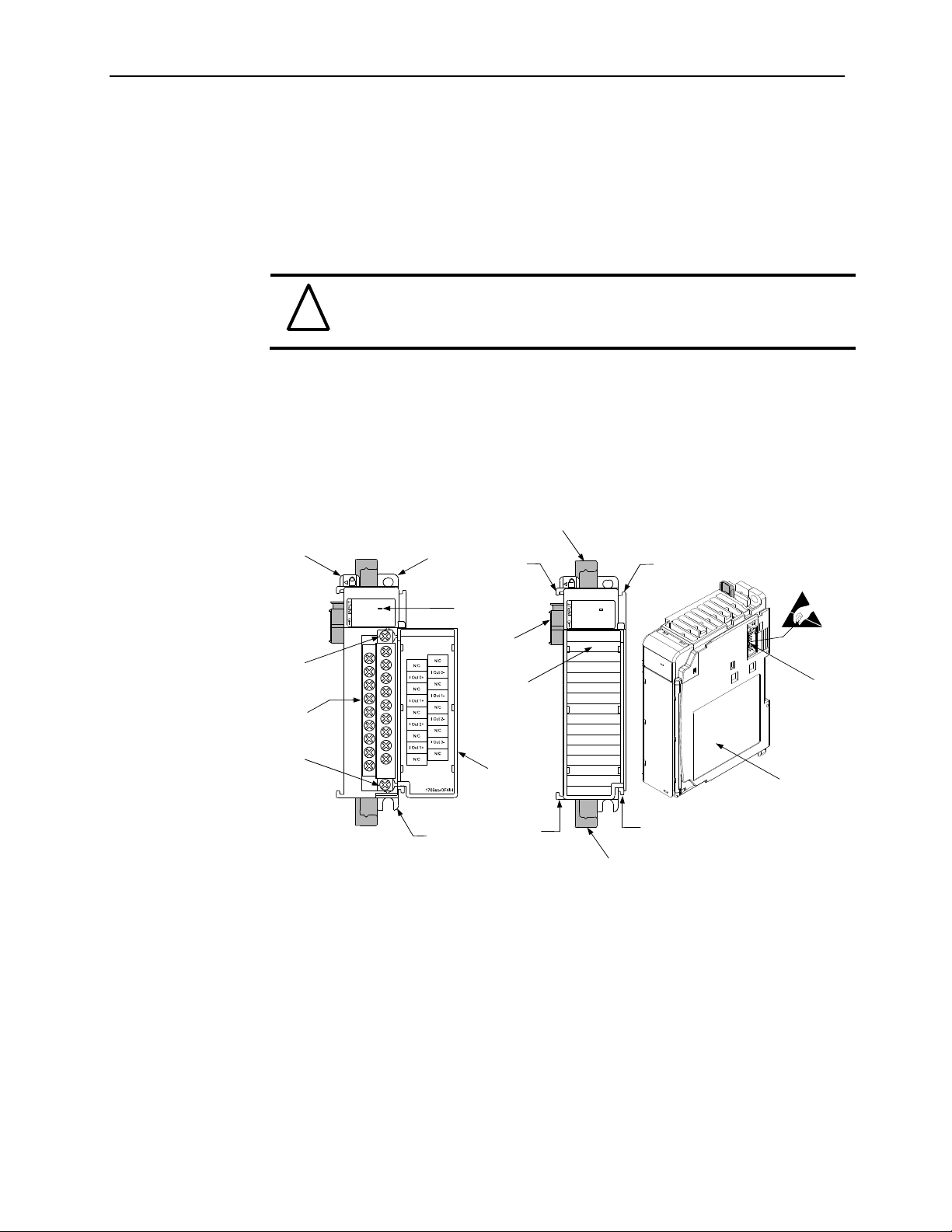
manual for more information. The illustration below shows the module’s hardware
features.
Figure 1-1
channel to channel isolation.
8a
1
OK
HART
10a
2a
DANGE R
Do Not Remove RTB Under
Power Unless Area is NonHazardous
7a
3
OK
HART
7a
5a
9
10
10b
Ensure Adjacent Bus
Lever is Unlatche d/
Latched Before/After
Removing/Inserting
Module
2b
4
7b
7b
8b
Item Description
1 bus lever
2a upper panel mounting tab
2b lower panel mounting tab
3 module status LED
4 module door with terminal identification label
5a movable bus connector (bus interface) with femal e pins
5b stat ionary bus connector (bus interface) with male pins
6 nameplate label
7a upper tongue-and-groove slots
7b lowe r to n gue-and-groove slots
8a upper DIN rail latch
8b lower DIN rail latch
5b
6
User’s Manual 0300217-03 Rev. A
Page 11

Chapter 1: Module Overview
9 write-on label for user identification tags
10 removable terminal block (RTB) with finger-safe cover
10a RTB upper retaining screw
10b RTB lower retaining screw
1.3.1 General Diagnostic Features
The module contains a diagnostic LED that helps you identify the source of problems that
may occur during power-up or during normal channel operation. The LED indicates both
status and power. Power-up and channel diagnostics are explained in Chapter 9
Diagnostics and Troubleshooting.
Section 1.4
System
Overview
The modules communicate to the controller through the bus interface. The modules also
receive 5 and 24V dc power through the bus interface.
1.4.1 System Operation
At power-up, the module performs a check of its internal circuits, memory, and basic
functions. During this time, the module status LED remains off. If no faults are found
during power-up diagnostics, the module status LED is turned on.
After power-up checks are complete, the module waits for valid channel configuration
data. If an invalid configuration is detected, the module generates a configuration error.
Once a channel is properly configured and enabled, it continuously converts the output
command value (i.e. output words 0 to 3) to a proportional analog signal that is within the
output range selected for that channel.
Each time a channel command value is read by the output module, that data value is
tested by the module for an over-range or under-range condition. If such a condition is
detected, a unique bit is set in the channel status word. The channel status word is
described in Section 6.3 Input Data File.
Using the module image table, the controller reads the two’s complement binary
converted input data from the module. This typically occurs at the end of the program
scan or when commanded by the control program. If the controller and the module
determine that the data transfer has been made without error, the data is used in the
control program.
1-3
User’s Manual 0300217-03 Rev. A
Page 12
Compact™ IO Isolated HART Analog Output Module
1-4
Section 1.5
Module
Operation
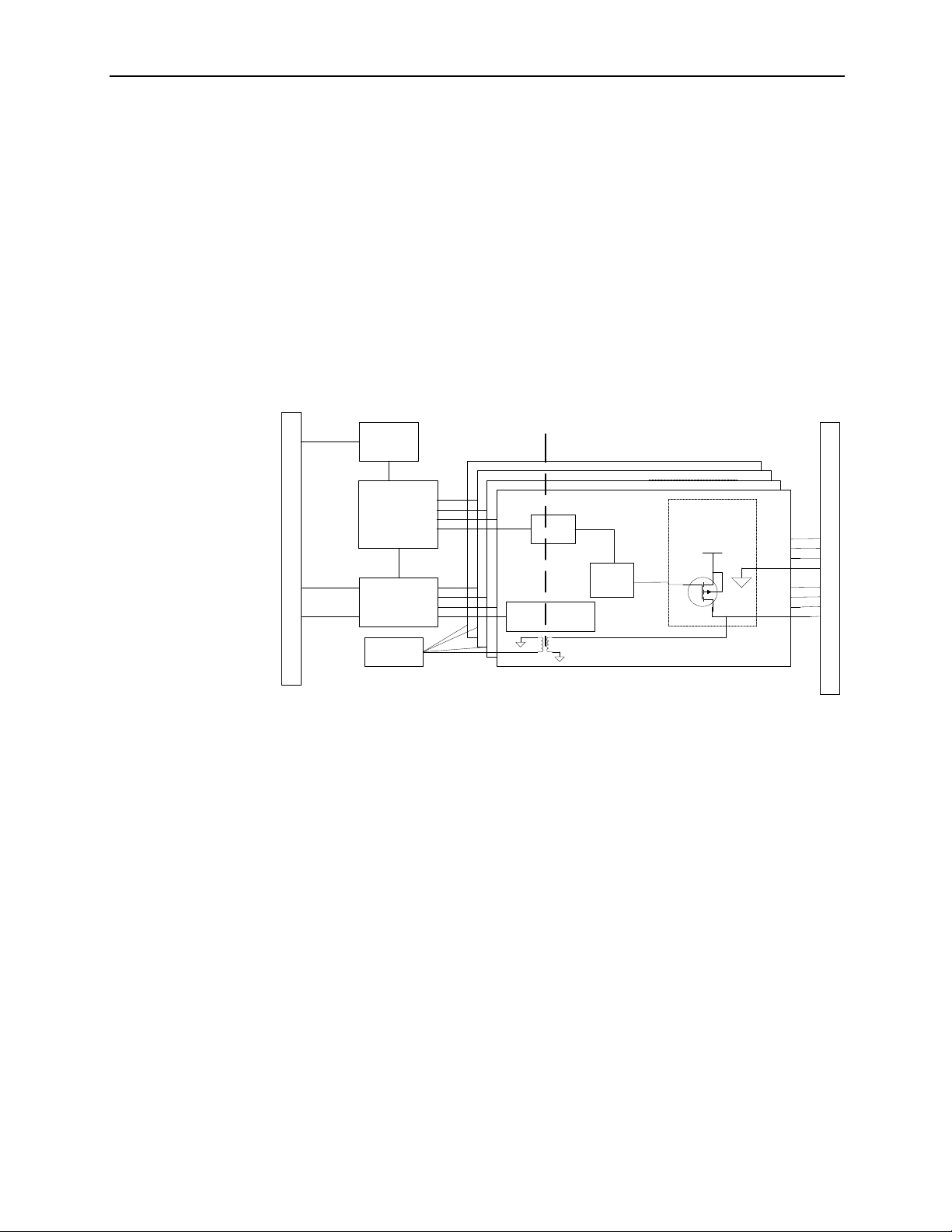
When the module receives a new command value from the output image, the module’s
circuitry converts the digital value to an analog current signal using a DAC (Digital to
Analog Converter). The resulting signal is made available for the specific channel via the
removable terminal block. If HART is enabled on a channel, the HART data is acquired
my means of an onboard HART modem.
Note: The HART data is sent and received asynchronously from the analog
acquisition process and therefore does not directly affect the analog update time.
See the block diagram below.
Figure 1-2
MERCURY
ASIC
500 VDC ISOLATION
OUTPUT CIRCUIT x4
BACKPLANE CONNECTOR
CPU
64K Flash/
2K RAM
V TO
24
12V
POWER
SUPPLY
HART
MODEM
OPTOS
OPTOS
OPTOS
OPTOS
ISOLATED +/-15V
ISOLATED +/-15V
SUPPLY
ISOLATED +/-15V
SUPPLY
ISOLATED +
SUPPLY
SUPPLY
16 BIT
-15V
DA
16 BIT
DA
C
16 BIT
16 BIT
C
C
DAC
DA
-
+
-
+15
VOUT
+
-
+15
V
VOUT
+
+15
V
VOUT
+15
V
GND
V
GND
GND
GND
IOUT
IOUT
IOUT
IOUT
BLOCK
The module is designed to support up to 4 isolated channels which can be independently
configured for current, or current with HART.
The HART data, if enabled, is converted directly to a block of twenty controller input
tags. The data within this block of twenty tags is multiplexed. For information on HART
and how to demultiplex the HART data, refer to Chapter 7.
TERMINAL
RET
User’s Manual 0300217-03 Rev. A
Page 13

Section 2.1
Before
You Begin
Chapter 2
Quick Start for Experienced
Users
This chapter can help you get started using the 1769sc-OF4IH isolated HART analog
output module. We base the procedures here on the assumption that you have an
understanding of Allen-Bradley controllers. You should understand electronic process
control and be able to interpret the ladder logic instructions required to generate the
electronic signals that control your application.
Because it is a start-up guide for experienced users, this chapter does not contain detailed
explanations about the procedures listed. It does, however, reference other chapters in
this book where you can get more information about applying the procedures described in
each step.
If you have any questions or are unfamiliar with the terms used or concepts presented in
the procedural steps, always read the referenced chapters and other recommended
documentation before trying to apply the information.
Section 2.2
Required
Tools and
Equipment
Section 2.3
What You
Need To Do
Have the following tools and equipment ready:
Medium blade or cross-head screwdriver
Analog output device
Shielded, twisted-pair cable for wiring (Bel den ™ 8 76 1 o r equivalent for current
outputs)
Controller (for example, a MicroLogix™ 1500 or CompactLogix™ controller)
Programming device and software (for example, RSLogix 500™ or RSLogix
5000™)
This chapter covers:
1. Ensuring that your power supply is adequate
2. Attaching and locking the module
3. Wiring the module
4. Configuring the module
5. Going through the startup procedure
6. Monitoring module operation
User’s Manual 0300217-03 Rev. A
Page 14
2-2
Compact IO™ Isolated HART Analog Output Module
Step 1: Ensure that your 1769 system
power supply
1
has sufficient current
output to support your system
configuration. Reference
Chapter 3 (Installation and Wiring)
The modules maximum current draw is shown below:
5V dc 24V dc
180 mA 200 mA
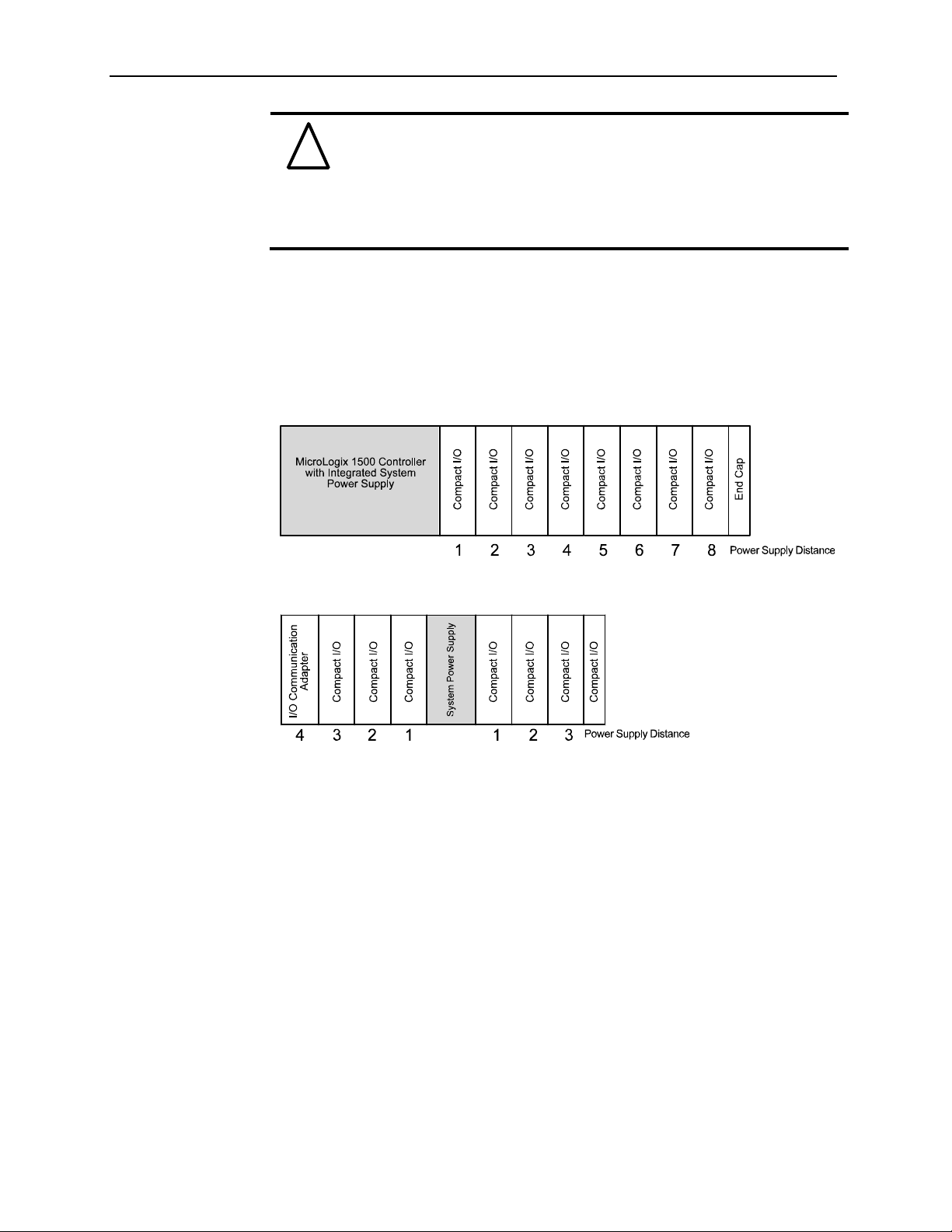
NOTE: The module cannot be located more than 8 modules away from the system
power supply.
Step 2: Attach and lock the module. Reference
Chapter 3 (Installation and Wiring)
Remove power before removing or inserting this module. If you remove or insert a
module with power applied an electrical arc may occur.
NOTE: The module can be panel or DIN rail mounted. Modules can be asse mbl e d
before or after mounting.
Remove power before removing or inserting this module. If you
!
Attention
remove or insert a module with power applied an electrical arc may
occur.
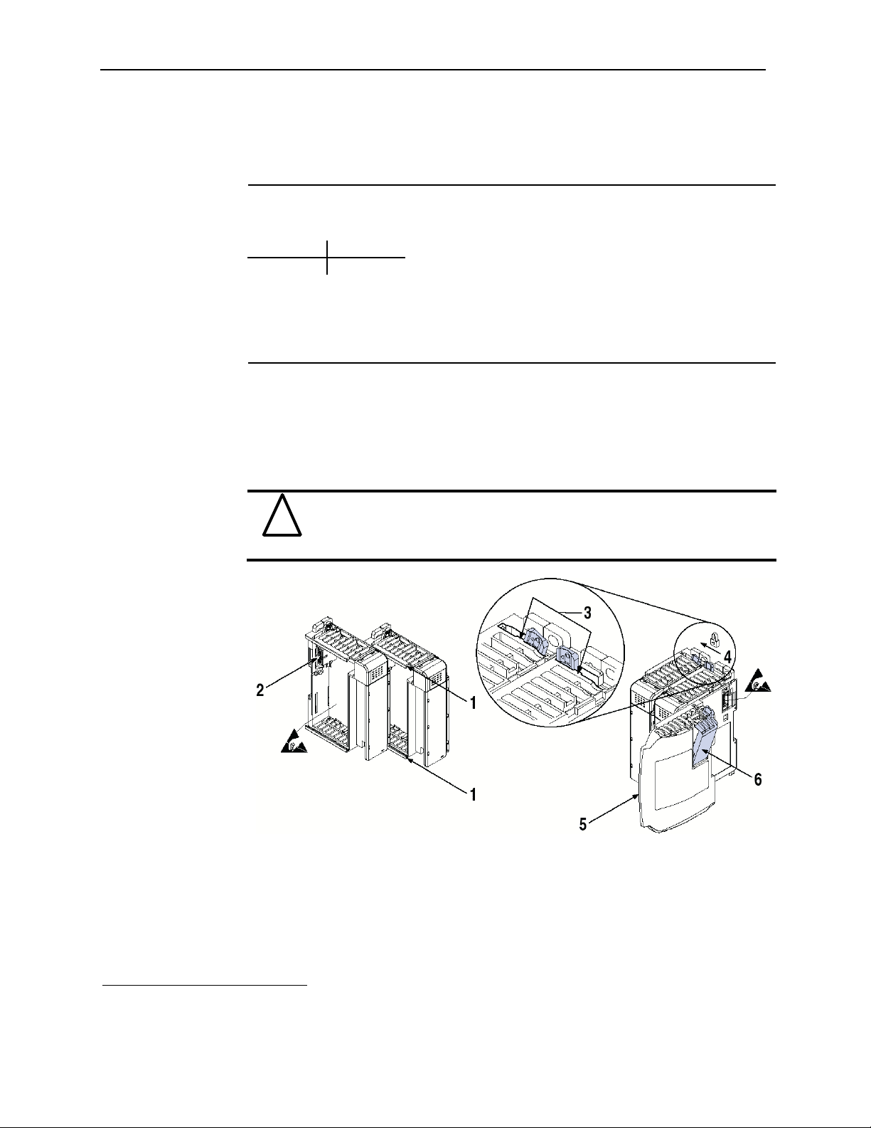
1. Check that the bus lever of the module to be installed is in the unlocked (fully right)
position.
2. Use the upper and lower tongue-and-groove slots (1) to secure the modules together
(or to a controller).
3. Move the module back along the tongue-and-groove slots until the bus connectors
(2) line up with each other.
4. Push the bus lever back slightly to clear the positioning tab (3). Use your fingers or a
small screwdriver.
1
The system power supply could be a 1769-PA2, -PB2, -PA4, -PB4, or the internal supply of the MicroLogix 1500
packaged controller.
User’s Manual 0300217-03 Rev. A
Page 15

Chapter 2: Quick Start For Experienced Users
5. To allow communication between the controller and module, move the bus lever
fully to the left (4) until it clicks. Ensure it is locked firmly in place.
6. Attach an end cap terminator (5) to the last module in the system by using the
tongue-and-groove slots as before.
7. Lock the end cap bus terminator (6).
When attaching I/O modules it is very important that the bus connectors
!
Attention
!
Attention
Step 3: Wire the module. Reference
Follow the guidelines below when wiring the module.
General
Power and output wiring must be in accordance wit h Class 1, Di vi sion 2 wiring
Channels are isolated from one another by ±500V dc maximum.
Route field wiring away from any other wiring and keep it as far as possible from
Routing field wiring in a grounded conduit can reduce electrical noise.
If field wiring must cross ac or power cables, ensure that they cross at right angles.
are securely locked together to ensure proper electrical connection.
A 1769-ECR or 1769-ECL right or left end cap respectively must be used
to terminate the end of the 1769 communication bus.
Chapter 3 (Installation and Wiring)
methods, Article 501-4(b) of the National Electric Code, NFPA 70, and in
accordance with the authority having jurisdiction.
sources of electrical noise, such as motors, transformers, contactors, and ac devices.
As a general rule, allow at least 15.2 cm (6 in.) of separation for every 120V of
power.
2-3
Terminal Block
For current output devices, use Belden 8761 shielded, twisted-pair wire (or
equivalent) to ensure proper operation and high immunity to electrical noise.
To ensure optimum accuracy, limit overall cable impedance by keeping a cable as
short as possible. Locate the module as close to input devices as the application
permits.
Grounding
This product is intended to be mounted to a well-grounded mounting surface such as
a metal panel. Additional grounding connections from the module’s mounting tabs or
DIN rail (if used) are not required unless the mounting surface cannot be grounded.
Keep cable shield connections to ground as short as possible.
Ground the shield drain wire at one end only. The preferred location is as follows.
Refer to Industrial Automation Wiring and Grounding Guidelines, Allen-Bradley
publication 1770-4.1, for additional information.
User’s Manual 0300217-03 Rev. A
Page 16
2-4
Compact IO™ Isolated HART Analog Output Module
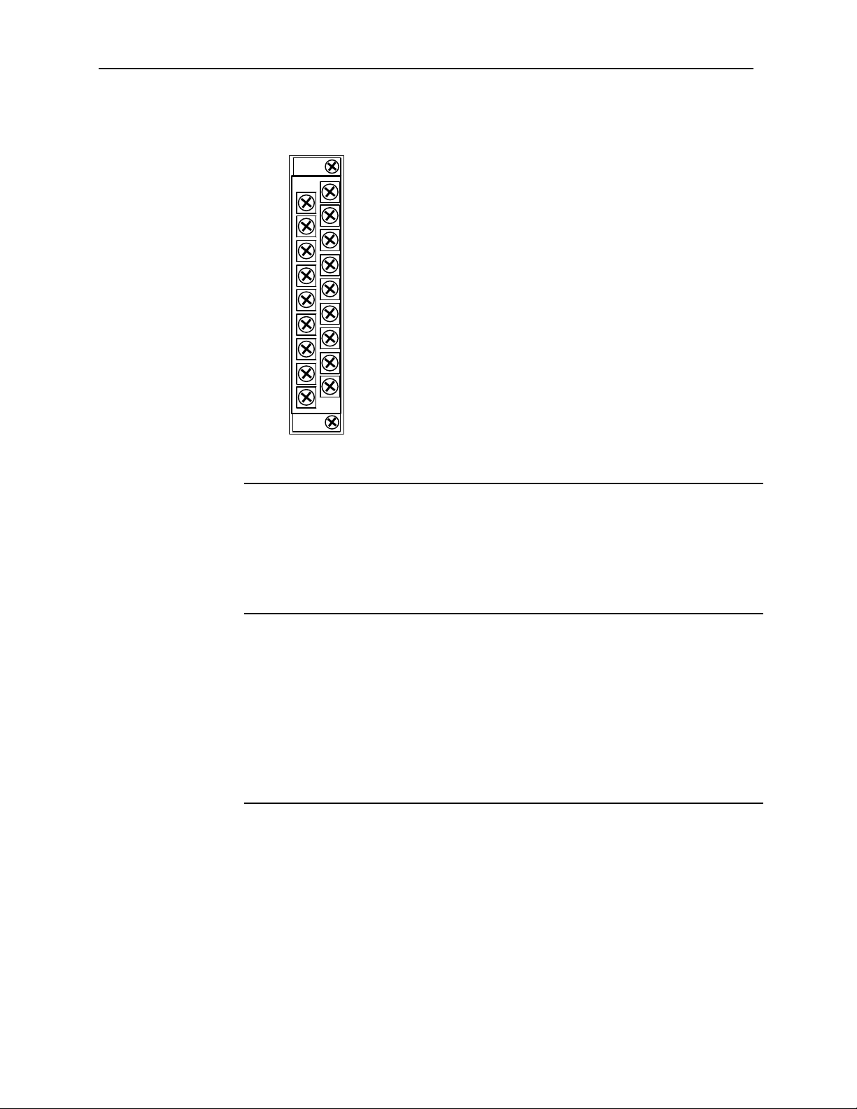
The terminal block layout is shown below:
Figure 2-1
N/C
I Out 0+
N/C
I Out 1+
N/C
I Out 2+
N/C
I Out 3+
N/C
N/C
I Out 0N/C
I Out 1N/C
I Out 2N/C
I Out 3N/C
Step 4: Configure the module for the
Reference
proper controller.
Chapter 4 (Configuring the OF4IH for
CompactLogix Using
RSLogix 5000) or Chapter 5 (Configuring
the OF4IH for a MicroLogix 1500 Using
RSLogix 500)
Step 5: Configure the module. Reference
Chapter 6 (Module Data, Status, and
Channel Configuration)
The configuration file is typically modified using the programming software compatible
with your controller. It can also be modified through the control progr am, if supported by
the controller. See 0 Module
Configuration
Configuration for more information.
Step 6: Go through the startup
procedure. Reference
Chapter 9 (Diagnostics and
Troubleshooting)
1. Apply power to the controller system.
2. Download your program, which contains the Isolated HART module configuration
settings, to the controller.
3. Put the controller in Run mode. During a normal start-up, the module status LED
turns on.
NOTE: If the module status LED does not turn on, cycle power. If the condition
persists, contact your local distributor or Spectrum Controls for assistance.
User’s Manual 0300217-03 Rev. A
Page 17

Chapter 2: Quick Start For Experienced Users
Step 7: Monitor the module status to
check if the module is operating
correctly Reference
Chapter 9 (Diagnostics and
Module and channel configuration errors are reported to the controller. These errors are
typically reported in the controller’s I/O status file. Channel status data is also reported in
the module’s input data table, so these bits can be used in your control program to flag a
channel error.
Troubleshooting)
2-5
User’s Manual 0300217-03 Rev. A
Page 18

2-6
Compact IO™ Isolated HART Analog Output Module
User’s Manual 0300217-03 Rev. A
Page 19

Section 3.1
Compliance to
European Union
Directives
Chapter 3
Installation and Wiring
This chapter explains how to:
Determine the power requirements for the module
Avoid electrostatic damage
Install the module
Wire the module’s terminal block
Wire output devices
This product is approved for installation within the European Union and EEA regions. It
has been designed and tested to meet the following directives.
3.1.1 EMC Directive
The 1769sc-OF4IH module is tested to meet Council Directive 89/336/EEC
Electromagnetic Compatibility (EMC) and the following standards, in whole or in part,
documented in a technical construction file:
EN 50081-2 EMC – Generic Emission Standard, Part 2 - I nd ustri al En vi r onment
EN 50082-2 EMC – Generic Immunity Standar d, Part 2 - I nd ustri al E n vironment
This product is intended for use in an industrial environment.
3.1.2 Low Voltage Directive
This product is tested to meet Council Directive 73/23/EEC Low Voltage, by applying
the safety requirements of EN 61131-2 Programmable Controllers, Part 2 – Equipment
Requirements and Tests. For specific information required by EN61131-2, see the
appropriate sections in this publication, as well as the following Allen-Bradley
publications:
Industrial Automation, Wiring and Grounding Guidelines for Noise Immunity,
publication 1770-4.1
Automation Systems Catalog, publication B113
3.1.3 CE Safety
This product is designed to, and verified compliance with, European Union Safety
Standards:
EN61131-2
EN61010-1
User’s Manual 0300217-03 Rev. A
Page 20

3-2
Compact IO™ Isolated HART Analog Output Module
Section 3.2
Power
Requirements
The module receives power through the bus interface from the +5V dc/ +24V dc system
power supply. The maximum current drawn by the module is shown in the table below.
Module Current Draw at 5V dc at 24V dc
180 mA 200 mA
Section 3.3 General
Considerations
Compact I/O is suitable for use in an industrial environment when installed in accordance
with these instructions. Specifically, this equipment is intended for use in clean, dry
environments (Pollution degree 2
2
II
(IEC 60664-1)3
1
and to circuits not exceeding Over Voltage Category
3.3.1 Hazardous Location Considerations
This equipment is suitable for use in Class I, Division 2, Groups A, B, C, D or nonhazardous locations only. The following WARNING statement applies to use in
hazardous locations.
EXPLOSION HAZARD
!
Attention
Substitution of components may impair suitability for Class I,
Division2.
Do not replace components or disconnect equipment unless
power has been switched off or the area is known to be nonhazardous.
Do not connect or disconnect components unless power has
been switched off or t he area is known to be non-hazardous.
This product must be installed in an enclosure.
All wiring must comply with N.E.C. article 501-4( b).
3.3.2 Prevent Electrostatic Discharge
Electrostatic discharge can damage integrated circuits or
!
Attention
1
Pollution Degree 2 is an environment where, normally, only non-conductive pollution occurs except that
occasionally a temporary conductivity caused by condensation shall be expected.
2
Over Voltage Category II is the load level section of the electrical distribution system. At this level transient
voltages are controlled and do not exceed the impulse voltage capability of the product’s insulation.
3
Pollution Degree 2 and Over Voltage Category II are International Electrotechnical Commission (IEC)
designations.
User’s Manual 0300217-03 Rev. A
semiconductors if you touch analog I/O module bus connector pins or
the terminal block on the output module. Follow these guidelines when
you handle the module:
Touch a grounded object to discharge static potential.
Wear an approved wrist-strap grounding device.
Do not touch the bus connector or connector pins.
Do not touch circuit components inside the module.
If available, use a static-safe work station.
When it is not in use, keep the module in its static-shield bag.
Page 21

Chapter 3: Installation and Wiring
3-3
3.3.3 Remove Power
Remove power before removing or inserting this module. When you
!
Attention
remove or insert a module with power applied, an electrical arc may
occur. An electrical arc can cause personal injury or property damage
by:
Sending an erroneous signal to your system’s field devices,
causing unintended machine motion
Causing an explosion in a ha zardous environment
Electrical arcing causes excessive wear to contacts on both the
module and its mating connector and may lead to premature
failure.
3.3.4 Selecting a Location
Reducing Noise
Most applications require installation in an industrial enclosure to reduce the effects of
electrical interference. Analog outputs are highly susceptible to electrical noise. Electrical
noise coupled to the analog outputs will reduce the performance (accuracy) of the
module.
Group your modules to minimize adverse effects from radiated electrical noise. Consider
the following conditions when selecting a location for the analog modu le. Position the
module:
Away from sources of electrical noise such as hard-contact switches, relays, and AC
motor drives
Away from high voltage conductors
In addition, route shielded, twisted-pair analog input wiring away from any high voltage
I/O wiring.
Reducing Heat
To avoid complications when operating in ambient temperatures in excess of 55 degrees
C, the following recommendations should be followed. Position the module:
Away from heat sources such as transformers, variable frequency drives, and cabinet
heaters.
Avoid installing the module adjacent to modules which generate over 4 W of heat,
such as the 1769-HSC. The table below lists modules which should be avoided if
possible:
Table 3-1 (Modules To Avoid)
Module Catalog Max Thermal Dissipation
1769-ADN 4.7
1769-HSC 6.2
1769-IQ32 4.8
1769-OW16 4.8
1769-OB32 4.5
User’s Manual 0300217-03 Rev. A
Page 22
3-4
Compact IO™ Isolated HART Analog Output Module
If the OF4IH is to be installed adjacent to one of the modules listed in
!
Attention
Power Supply Distance
You can install as many modules as your power supply can support. However, all 1769
I/O modules have a power supply distance rating. The maximum I/O module rating is 8,
which means that a module may not be located more than 8 modules away from the
system power supply.
Figure 3-1
the table above and the ambient temperature is in excess of 55°C, then
derating of the module is required to avoid thermal shutdown. Assume
the thermal dissipation of the OF4IH to be 2W fixed plus an additional
0.5W per channel. For example, if the OF4IH is to be installed
adjacent to the 1769-HSC, no more than 2 channels should be used on
the OF4IH.
Section 3.4
System Assembly
The module can be attached to the controller or an adjacent I/O module before or after
mounting. For mounting instructions, see Panel Mounting Using the Dimensional
Template, or DIN Rail Mounting. To work with a system that is already mounted, see
Replacing a Single Module within a System.
The following procedure shows you how to assemble the Compact I/O system.
User’s Manual 0300217-03 Rev. A
Page 23
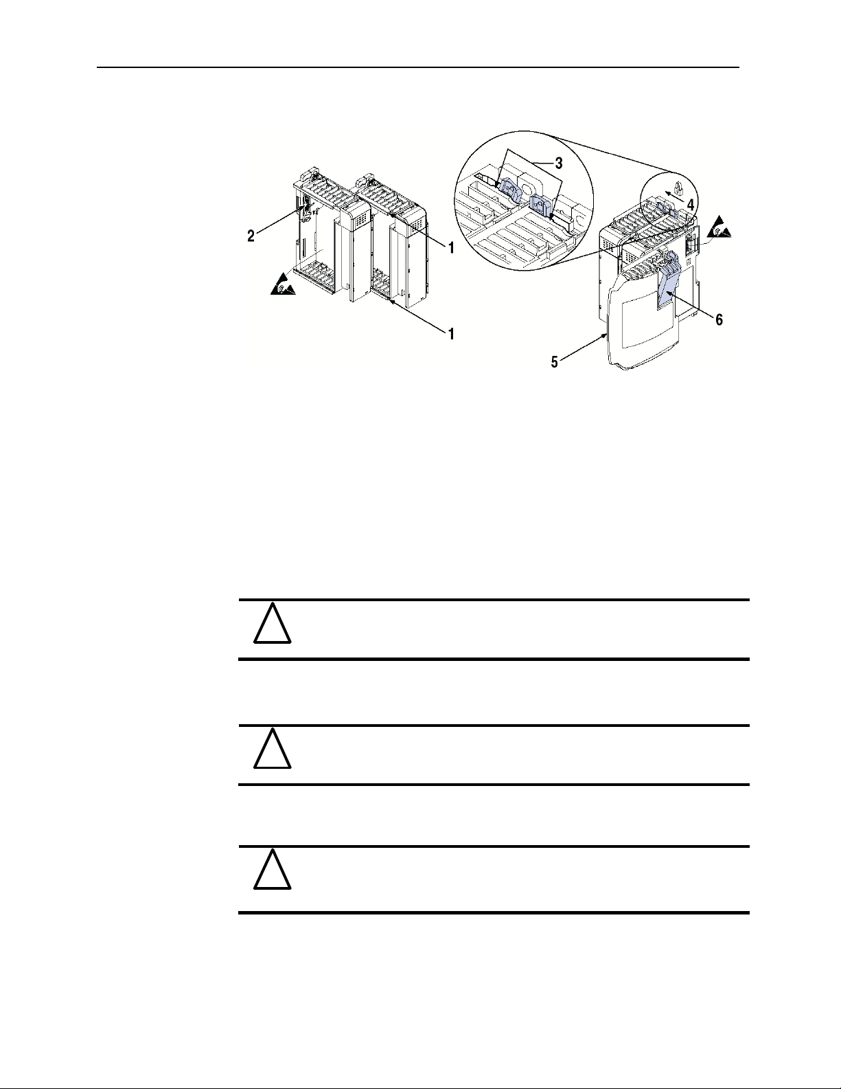
Figure 3-2
Chapter 3: Installation and Wiring
3-5
1. Disconnect power.
2. Check that the bus lever of the module to be installed is in the unlocked (fully right)
position.
NOTE: If the module is being installed to the left of an existing module, check that the
right-side adjacent module’s bus lever is in the unlocked (fully right) position.
3. Use the upper and lower tongue-and-groove slots (1) to secure the modules together
(or to a controller).
4. Move the module back along the tongue-and-groove slots until the bus connectors
(2) line up with each other.
5. Push the bus lever back slightly to clear the positioning tab (3). Use your fingers or a
small screwdriver.
6. To allow communication between the controller and module, move the bus lever
fully to the left (4) until it clicks. Ensure it is locked firmly in place.
When attaching I/O modules, it is very imp ortant that the bus
!
Attention
7. Attach an end cap terminator (5) to the last module in the system by using the
tongue-and-groove slots as before.
8. Lock the end cap bus terminator (6).
!
Attention
connectors are securely locked together to ensure proper electrical
connection.
A 1769-ECR or 1769-ECL right or left end cap respectively must be
used to terminate the end of the bus.
Section 3.5
Mounting
!
Attention
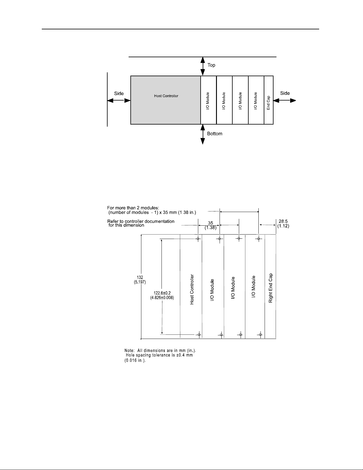
3.5.1 Minimum Spacing
Maintain spacing from enclosure walls, wireways, adjacent equipment, etc. Allow 50 mm
(2 in.) of space on all sides for adequate ventilation, as shown below:
User’s Manual 0300217-03 Rev. A
During panel or DIN rail mounting of all devices, be sure that all
debris (metal chips, wire strands, etc.) is kept from falling into the
module. Debris that falls into the module could cause damage at
power up.
Page 24
3-6
Compact IO™ Isolated HART Analog Output Module
Figure 3-3
3.5.2 Panel Mounting
Mount the module to a panel using two screws per module. Use M4 or #8 panhead
screws. Mounting screws are required on every module.
Panel Mounting Using the Dimensional Template
Figure 3-4
Panel Mounting Procedure Using Modules as a Template
The following procedure allows you to use the assembled modules as a template for
drilling holes in the panel. If you have sophisticated panel mounting equipment, you can
use the dimensional template provided on the previous page. Due to module mounting
hole tolerance, it is important to follow these procedures:
1. On a clean work surface, assemble no more than three modules.
User’s Manual 0300217-03 Rev. A
Page 25

Section 3.6
Replacing a Single
Module within
a System
Chapter 3: Installation and Wiring
2. Using the assembled modules as a template, carefully mark the center of all module-
mounting holes on the panel.
3. Return the assembled modules to the clean work surface, including any previously
mounted modules.
4. Drill and tap the mounting holes for the recommended M4 or #8 screw.
5. Place the modules back on the panel, and check for proper hole alignment.
6. Attach the modules to the panel using the mounting screws.
NOTE If mounting more modu les, mount only the last one of this group and put the
others aside. This reduces remounting time during drilling and tapping of the next
group.
7. Repeat steps 1 to 6 for any remaining modules.
3-7
3.5.3 DIN Rail Mounting
The module can be mounted using the following DIN rails:
35 x 7.5 mm (EN 50 022 - 35 x 7.5), or
35 x 15 mm (EN 50 022 - 35 x 15).
Before mounting the module on a DIN rail, close the DIN rail latches. Press the DIN rail
mounting area of the module against the DIN rail. The latches will momentarily open and
lock into place.
The module can be replaced while the system is mounted to a panel (or DIN rail). Follow
these steps in order:
1. Remove power. See important note at the beginning of this chapter.
2. On the module to be removed, remove the upper and lower mounting screws from
the module (or open the DIN latches using a flat-blade or phillips-style screwdriver).
3. Move the bus lever to the right to disconnect (unlock) the bus.
4. On the right-side adjacent module, move its bus lever to the right (unlock) to
disconnect it from the module to be removed.
5. Gently slide the disconnected module forward. If you feel excessive resistance,
check that the module has been disconnected from the bus, and that both mounting
screws have been removed (or DIN latches opened).
NOTE: It may be necessary to rock the module slightly from front to back to remove it,
or, in a panel-mounted system, to loosen the screws of adjacent modules.
6. Before installing the replacement module, be sure that the bus lever on the module to
be installed and on the right-side adjacent module or end cap are in the unlocked
(fully right) position.
7. Slide the replacement module into the open slot.
8. Connect the modules together by locking (fully left) the bus levers on the
replacement module and the right-side adjacent module.
9. Replace the mounting screws (or snap the module onto the DIN rail).
Section 3.7
Field Wiring
Connections &
System Wiring
Guidelines
Consider the following when wiring your system:
User’s Manual 0300217-03 Rev. A
Page 26

3-8
Compact IO™ Isolated HART Analog Output Module
General
Power and output wiring must be in accordance wit h Class 1, Di vi sion 2 wiring
methods, Article 501-4(b) of the National Electric Code, NFPA 70, and in
accordance with the authority having jurisdiction.
Channels are isolated from one another by ±500 Vdc maximum.
Route field wiring away from any other wiring and as far as possible from sources of
electrical noise, such as motors, transformers, contactors, and ac devices. As a
general rule, allow at least 15.2 cm (6 in.) of separation for every 120V of power.
Routing field wiring in a grounded conduit can reduce electrical noise.
If field wiring must cross ac or power cables, ensure that they cross at right angles.
If multiple power supplies are used with analog millivolt inputs, the power supply
commons must be connected.
Terminal Block
For voltage and current sensors, use Belden 8761 shielded, twisted-pair wire (or
equivalent) to ensure proper operation and high immunity to electrical noise.
To ensure optimum accuracy, limit overall cable impedance by keeping a cable as
short as possible. Locate the module as close to input devices as the application
permits.
Grounding
This product is intended to be mounted to a well-grounded mounting surface such as
a metal panel. Additional grounding connections from the module’s mounting tabs or
DIN rail (if used) are not required unless the mounting surface cannot be grounded.
Keep cable shield connections to ground as short as possible.
Ground the shield drain wire at one end only. The typical location is as follows.
If it is necessary to connect the shield drain wire at the module end, connect it to
earth ground using a panel or DIN rail mounting screw.
Refer to Industrial Automation Wiring and Grounding Guidelines, Allen-Bradley
publication 1770-4.1, for additional information.
Noise Prevention
To limit the pickup of electrical noise, keep analog signal wires as far as possible
from power and load lines.
If noise persists for a device, try grounding the opposite end of the cable shield. (You
should only ground one end at a time.)
3.7.2 Terminal Door Label
A removable, write-on label is provided with the module. Remove the label from the
door, mark your unique identification of each terminal with permanent ink, and slide the
label back into the door. Your markings (ID tag) will be visible when the module door is
closed.
3.7.3 Removing and Replacing the Terminal Block
When wiring the module, you do not have to remove the terminal block. If you remove
the terminal block, use the write-on label located on the side of the terminal block to
identify the module location and type.
User’s Manual 0300217-03 Rev. A
Page 27
Chapter 3: Installation and Wiring
3-9
Figure 3-5
To remove the terminal block, loosen the upper and lower retaining screws. The terminal
block will back away from the module as you remove the screws. When replacing the
terminal block, torque the retaining screws to 0.46 Nm (4.1 in-lbs).
3.7.4 Wiring the Finger-Safe Terminal Block
When wiring the terminal block, keep the finger-safe cover in place.
1. Loosen the terminal screws to be wired.
2. Route the wire under the terminal pressure plate. You can use the bare wire or a
spade lug. The terminals accept a 6.35 mm (0.25 in.) spade lug.
NOTE: The terminal screws are non-captive. Therefore, it is possible to use a ring lug
[maximum 1/4 inch o.d. with a 0.139 inch minimum i.d. (M3.5)] with the module.
3. Tighten the terminal screw making sure the pressure plate secures the wire.
Recommended torque when tightening terminal screws is 0.68 Nm (6 in-lbs).
NOTE: If you need to remove the finger-safe cover, insert a screwdriver into one of the
square, wiring holes and gently pry the cover off. If you wire the terminal block with
the finger-safe cover removed, you may not be able to put it back on the terminal block
because the wires will be in the way.
Wire Size and Terminal Screw Torque
Each terminal accepts up to two wires with the following restrictions:
Wire Type Wire Size Terminal Screw
Torque
Solid Cu-90° C
(194°F)
Stranded Cu-90°C
(194°F)
#14 to #22 AWG
(1.63 to 0.65 mm
#16 to #22 AWG
(1.63 to 0.65 mm
0.68 Nm (6 in-lbs) 0.46 Nm (4.1 in-lbs)
2
)
0.68 Nm (6 in-lbs) 0.46 Nm (4.1 in-lbs)
2
)
Retaining Screw
Torque
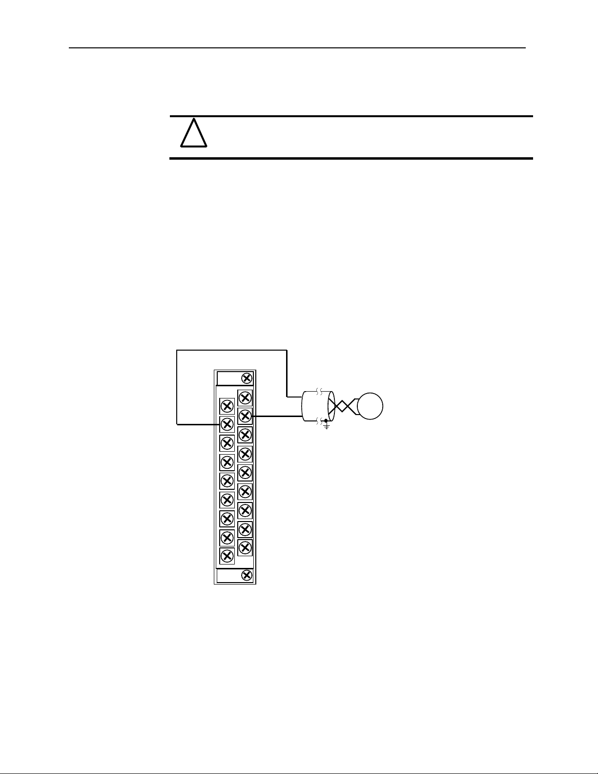
3.7.5 Wiring the Module
Before wiring any module, disconnect power from the system power
!
Attention
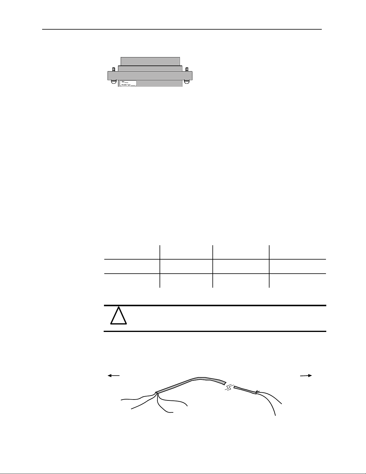
After the module is properly installed, follow the wiring procedure below, using the
proper cable, Belden 8761.
Figure 3-6
supply.
Signal Wire
Signal Wire
Drain Wire
T o Analog OutputTo Module
Cable
Signal Wire
Foil Shield
Signal Wire
User’s Manual 0300217-03 Rev. A
Page 28
3-10
Compact IO™ Isolated HART Analog Output Module
To wire your module follow these steps.
1. At each end of the cable, strip some casing to expose the individual wires .
2. Trim the signal wires to 2-inch (5 cm) lengths. Strip about 3/16 inch (5 mm) of
insulation away to expose the end of the wire.
Be careful when stripping wires. Wire fragments that fall into a module
!
Attention
could cause damage at power up.
3. At one end of the cable, twist the drain wire and foil shield together, bend them away
from the cable, and apply shrink wrap. Then earth ground at the preferred location
based on the type of sensor you are using. See Grounding for more details.
4. At the other end of the cable, cut the drain wire and foil shield back to the cable and
apply shrink wrap.
5. Connect the signal wires to the terminal block. Connect the other end of the cable to
the analog output device.
6. Repeat steps 1 through 5 for each channel on the module.
1.1.6 Wiring Diagram
Figure 3-7
4 to 20 mA Out
N/C
I Out 0+
N/C
I Out 1+
N/C
I Out 2+
N/C
I Out 3+
N/C
N/C
I Out 0-
N/C
I Out 1N/C
I Out 2N/C
I Out 3N/C
+
Load
-
3.7.7 Calibration
The isolated HART module is initially calibrated at the factory.
User’s Manual 0300217-03 Rev. A
Page 29

Chapter 4
Configuring the OF4IH for
CompactLogix Using
RSLogix 5000
This chapter explains how to incorporate the OF4IH module into a CompactLogix system
using RSLogix 5000 programming software . The process of incorporating your HART
module into the CompactLogix system is similar to the process needed to add an AllenBradley module. You will use your RSLogix 5000 programming software to install and
configure your HART module.
An Add-On profile is available on our website to ease the installation of the module, if
you choose not to use the generic module profile. The Ad d -O n pr ofi l e d o wnload also
includes an RSLogix 5000 sample project demonstrating how to read and write HART
data to and from each channel. The sample project contains user defined data types,
configuration tags, input tags, output tags, and ladder samples needed to configure each
HART module. The topics discussed in this chapter include:
Setting up the generic profile
Using the Add-On profile
Understanding user defined dat a types
Adding the controller and program tags
Using the provided ladder sample
Section 4.1
Setting up the
Generic Profile
The generic profile defines the module for the CompactBus, so that the right number of
input, output and configuration words are reserved . To configure the generic profile you
can use the profile already created in the sample project, see Figure 4-1, or follow the
procedures outlined below.
Figure 4-1 (Pre-Defined Generic Profile)
User’s Manual 0300217-03 Rev. A
Page 30

4-2
Compact IO™ Isolated HART Analog Output Module
1. Create a new RSLogix 5000 project file. Click on the new project icon or on the
FILE pull-down menu and select NEW. The following screen appears:
Figure 4-2
2. Choose your controller type and enter a name for your project, then click OK.
The following main RSLogix 5000 screen appears:
User’s Manual 0300217-03 Rev. A
Page 31

Chapter 4: Configuring the OF4IH for CompactLogix Using RSLogix 5000
Figure 4-3
4-3
3. In the ControllerOrganizer on the left of the screen, right click on
“[0]CompactBus Local”, select New Module, and the following screen appears:
Figure 4-4
User’s Manual 0300217-03 Rev. A
Page 32

4-4
Compact IO™ Isolated HART Analog Output Module
4. This screen is used to narrow your search for I/O modules to configure into your
system. With the initial release of the CompactLogix5320 controller, this screen
only includes the “Generic 1769 Module”. Click the OK button and the
following default Generic Profile screen appears:
Figure 4-5
5. First, select the Comm Format (“Data – INT” for the 1769sc-OF4IH), then fill in
the name field. For this example, “OF4IH” is used to help identify the module
type in the Controller Organizer. The Description field is optional and may be
used to provide more details concerning this I/O module in your application.
The slot number must be selected next, although it will begin with the first
available slot number, 1, and increments automatically for each subsequent
Generic Profile you configure. For this example, the 1769sc-OF4IH HART
module is located in slot 1.
The Comm Format, Assembly Instance and Size values are listed in the
following table for the 1769sc-OF4IH HART module:
Table 4-1 (Generic Profile Parameters)
1769 I/O
Module
Comm
Format
OF4IH Data-INT Input
6. Enter the Assembly Instance numbers and their associated sizes for the 1769sc-
OF4IH module into the Generic Profile. When complete, the Generic Profile for
a 1769sc-OF4IH module should look like the following:
Parameter
Output
Config
Assembly
Instance
101
100
102
Size
(16-Bit)
70
50
42
User’s Manual 0300217-03 Rev. A
Page 33

Chapter 4: Configuring the OF4IH for CompactLogix Using RSLogix 5000
Figure 4-6
7. At this point you may click “Finish” to complete the configuration of your I/O
module.
Configure each I/O module in this manner. The CompactLogix5320 controller
supports a maximum of 8 I/O modules. The valid slot numbers to select when
configuring I/O modules are 1 through 8.
4-5
Section 4.2
Using
The Add-On
Profile
For RSLogix 5000 version 15 and greater an Add-On module profile is available for
download at (http://www.spectrumcontrols.com/downloads.htm). The Add-On profile
allows the user to add the OF4IH module to the RSLogix 5000 module pick list. The
profile provides configuration and information screens to the user, to simplify
installation. Follow the procedure below to install and use the Add-On profile.
Module firmware 2.0 and greater is required in order to use the Add-On
!
Attention
profile.
4.2.1 Installing the Add-On profile
1. Download the zipped file from the Spectrum Controls website and unzip the file.
http://www.spectrumcontrols.com/pdfs/abio/sc1769_hart_15.zip
2. Open the created folder and double-click on the MPSetup.exe file.
User’s Manual 0300217-03 Rev. A
Page 34

n
a
n
-
e
l
d
o
o
t“Ne
hSpe
e
4
l
e
u
s
l
o
e
c
l
m
s
L
o
m
n
V
c
m
V
n
s
4-6 Comp
ct IO™ Isolat
3. Fo
d HART Ana
low the onlin
log Output M
prompts.
dule
4.2.2 Ad
Once the pr
Configurati
1. In
2. W
ing the OF
files are insta
n. Follow th
he I/O Config
w Module”.
en the dialog
ctrum Contro
IH Modul
led you can a
procedure be
ration, right
creen opens,
s folder.
To Your
cess them thr
ow to add a
ouse click o
elect the “By
ogix Proje
ugh RSLogix
odule:
the 1769 Co
ender” tab a
t
5000 via the I
pactBus and
d expand the
/O
elect
User’s Ma
ual 0300217
03 Rev. A
Page 35

Chapter 4: Configuring the OF4IH for CompactLogix Using RSLogix 5000
3. Highlight the module and press the “OK” button.
4. Configure the module using the custom configuration screens.
Note: The 1769sc-IF4IH still requires ladder to demultiplex the HART data and send
HART messages via the controller. Please refer to the sample project packaged with
the profile install for more information.
Section 4.3
User Defined
Data Types
The sample project contains user defined data types which define the structure for tags
used within the project. The data types organize the HART data returned by the module
and are referenced throughout this manual, so it is highly recommended that these data
types be used whenever possible.
Select the data type you wish to copy from the Controller Organizer and paste it into
your project under user defined data types. See figure below.
Figure 4-7 (Copying Data Types)
4-7
Sample
Project
Drag and drop
one at a time
The user defined data types should be copied before copying the tags or
!
Attention
ladder.
Your
Project
User’s Manual 0300217-03 Rev. A
Page 36

4-8
Compact IO™ Isolated HART Analog Output Module
The table below gives a brief description of each data type.
Table 4-2 (User Defined Data Type Descriptions)
User Defined Data Type Description
ConfigurationStructure Defines the structure for the configuration tags used to
configure the module.
GetDeviceInfoStructure Defines the structure of the HART data returned by the
module when the module specific command, Get
Device Information, is sent to module.
OF4IHMessage This data type defines the structure for tags used to
send messages to and from the module using the paging
scheme.
OF4IHPassThruMsg Defines the structure for tags used to send HART pass
through messages to and from the module.
InputStructure Defines the structure for the input tags returned by the
module.
OutputStructure Defines the structure for the output tags used by the
module.
Packet0 Defines the data structure for HART packet 0. HART
packet zero contains device information for the
connected HART device.
Packet1 Defines the data structure for HART packet 1. HART
packet 1 is used to display the four dynamic variables
for the selected HART device.
Packet2 Defines the data structure for HART packet 2. HART
packet 2 is used to display the slot variables for the
connected HART device.
Packet3 Defines the data structure for HART packet 3. HART
packet 3 displays the ASCII message for the connected
HART device.
Packet4 Defines the data structure for HART packet 4. HART
packet 4 contains the extended status for the connected
HART device.
1
2
2
2
1
1
2
2
2
2
2
Section 4.4
Project Tags
The project tags were created to simplify the configuration of the module as well as
reduce confusion related to using only the module local tags. The tags defined in the
sample project utilize the user defined data types descri bed in the previous section.
The tags from the controller scope should be copied to your project before the tags
contained in the individual program sections. Open the controller tags on the sample
project and select the edit tags mode. Grab the tags you want to copy by using the left
mouse button and dragging. See figure below.
1
Refer to Chapter 6 for more details.
2
Refer to Chapter 7 for more details.
User’s Manual 0300217-03 Rev. A
Page 37

Chapter 4: Configuring the OF4IH for CompactLogix Using RSLogix 5000
Figure 4-8 (Copying Controller Tags)
4-9
Sample
Project
Copy and
paste tags
After copying the controller tags you can copy the program tags next. Follow the same
procedure shown in Figure 4-8.
The figures below show examples of the configuration tags, input tags and output tags.
Refer to Chapter 6 for information on how to configure the module and or reading the
input data. Refer to Chapter 7 for information regarding HART packet tags and passthrough tags.
Your
Project
User’s Manual 0300217-03 Rev. A
Page 38

4-10
Compact IO™ Isolated HART Analog Output Module
Figure 4-9 (Configuration Tags)
Figure 4-10 (Input Tags)
User’s Manual 0300217-03 Rev. A
Page 39

Chapter 4: Configuring the OF4IH for CompactLogix Using RSLogix 5000
Figure 4-11 (Output Tags)
4-11
User’s Manual 0300217-03 Rev. A
Page 40

4-12
p
Compact IO™ Isolated HART Analog Output Module
Section 4.5
Sample Project
Ladder
The ladder contained in the sample project is used to perform several different operations.
The main routine in the MainProgram is used to copy data from the user defined tags to
the module local tags. This data includes input, output and configuration settings for the
module.
The OF4IH0_Packet_Data routine in the MainProgram contains the ladder that
demultiplexes the HART data for each individual packet. Refer to Section 7.2 HART
Packet
Data for more information on HART and the HART packets.
The OF4IH0Messaging program contains several routines needed to send and receive
HART messages to and from the module and the connected HART devices.
To copy any of the ladder, programs or routines, follow the procedure below:
1. Select the program or routine.
2. Right mouse click and select copy.
3. Go to your project and select the appropriate program or task to place the new
routine or program.
4. Right mouse click and select paste.
The figure below outlines this procedure:
Figure 4-12 (Copying Routines or Programs)
Sample
Project
Copy
and
aste
You can follow a similar procedure for copying ladder as well.
1. Open the routine that contains the ladder you want to copy.
2. Select the rungs to copy.
3. Right mouse click and select copy.
4. Open the routine in your project where you wish to paste the new rungs.
Your
Project
User’s Manual 0300217-03 Rev. A
Page 41

Chapter 4: Configuring the OF4IH for CompactLogix Using RSLogix 5000
5. Right mouse click and select paste.
The figure below demonstrates this procedure:
Figure 4-13 (Copying Ladder)
4-13
Sample
Project
Your
Project
User’s Manual 0300217-03 Rev. A
Page 42

4-14
Compact IO™ Isolated HART Analog Output Module
User’s Manual 0300217-03 Rev. A
Page 43

Chapter 5
Configuring the OF4IH for a
MicroLogix 1500 Using
RSLogix 500
This chapter examines the 1769sc-OF4IH module’s addressing scheme and describes
module configuration using RSLogix 500 and a MicroLogix 1500 controller. This
chapter will cover the following:
Module Addressing
Configuring the OF4IH in a MicroLogix 1500 System
Using the Ladder Sample
Section 5.1
Module
Addressing
The following memory map shows the input, output, and configuration image tables for
the module. Detailed information on the image table is located in Chapter 6.
Figure 5-1 (Module Memory Map)
Memory Map
slot e
Input Image File
slot e
Configuration File
slot e
Output File
Input Image
70 Words
Configuration
42 Words
Output
50 Words
Bit 15
Word 0: Status Word 0
Word 1: Status Word 1
Word 2: Channel 0 Data Value
Word 3: Channel 1 Data Value
Word 4: Channel 2 Data Value
Word 5: Channel 3 Data Value
Words 6..25: HART Data
Word 26: Message Slave Control
Word 27: Response Size
Words 28..47: Message Response Buffer
Words 48..69: Reserved
Bit 15
Words 0..7: Channel 0 Configuration
Words 8..15: Channel 1 Configuration
Words 16..23: Channel 2 Configuration
Words 24..31: Channel 3 Configuration
Word 32: Pad
Word 33: HART Configuration Word
Word 34: Ch0 Slot Variables 0 & 1
Word 35: Ch0 Slot Variables 2 & 3
Word 36: Ch1 Slot Variables 0 & 1
Word 37: Ch1 Slot Variables 2 & 3
Word 38: Ch2 Slot Variables 0 & 1
Word 39: Ch2 Slot Variables 2 & 3
Word 40: Ch3 Slot Variables 0 & 1
Word 41: Ch3 Slot Variables 2 & 3
Word 0: Channel 0 Output Value
Word 1: Channel 1 Output Value
Word 2: Channel 2 Output Value
Word 3: Channel 3 Output Value
Word 4: Channel Alarm Unlatch
Word 5: HART Packet Just Scanned
Word 6: Message Master Control
Word 7: Request Size
Words 8..27: Message Request Buffer
Words 28..49: Reserved
Bit 15
Bit 1
Bit 1
Bit 1
User’s Manual 0300217-03 Rev. A
Page 44

5-2
Compact IO™ Isolated HART Analog Output Module
For example, to obtain the general status for channel 2 of the module located in slot e, use
address I:e.0/2.
Figure 5-2 (Address Example)
Slot
Word
Section 5.2
Configuring
the 1769sc-OF4IH
in a MicroLogix
1500 System
Input Fi le Type
Element
Delimiter
I:e.0/2
Bit
Delimiter
Word
Bit
Delimiter
NOTE: The end cap does not use a slot address.
This example takes you through configuring your 1769sc-OF4IH isolated HART analog
output module with RSLogix 500 programming software, assumes your module is
installed as expansion I/O in a MicroLogix 1500 system, and that RSLinx™ is properly
configured and a communications link has been established between the MicroLogix
processor and RSLogix 500.
It is recommended that a 1764-LRP series C processor with firmware
!
Attention
version 5 or higher be used. The LRP processor supports floating
point files, which is required to read floating point data from the
OF4IH.
Start RSLogix and create a MicroLogix 1500 application. The following screen appears:
User’s Manual 0300217-03 Rev. A
Page 45

Chapter 5: Configuring the OF 4IH for A MicroLogix 1500 Using RSLogix 500
Figure 5-3
5-3
While offline, double-click on the IO Configuration icon under the controller folder and
the following IO Configuration screen appears.
Figure 5-4
This screen allows you to manually enter expansion modules into expansion slots, or to
automatically read the configuration of the controller. To read the existing controller
configuration, click on the Read IO Config button.
A communications dialog appears, identifying the current communications configuration
so that you can verify the target controller. If the communication settings are correct,
click on Read IO Config.
User’s Manual 0300217-03 Rev. A
Page 46

5-4
Compact IO™ Isolated HART Analog Output Module
Figure 5-5
The actual I/O configuration is displayed. In this example, a second tier of I/O is attached
to the MicroLogix 1500 processor.
Figure 5-6
The 1769sc-OF4IH module is installed in slot 1. To configure the module, double-click
on the module/slot. The general configuration screen appears.
User’s Manual 0300217-03 Rev. A
Page 47

Chapter 5: Configuring the OF 4IH for A MicroLogix 1500 Using RSLogix 500
Figure 5-7
5-5
When using the read IO configuration feature in RSLogix, you need
!
Attention
To configure the module select the Generic Extra Data Configuration tab. Enter the
decimal equivalent of each configuration word. There are a total of 42 words that need to
be configured altogether. The module default settings are used if all the configuration
words are left at zero.
Figure 5-8
to manually enter 42 into the “extra data length” field.
NOTE: For a complete description of each of these parameters and the choices
available for each of them, refer to Chapter 6.
User’s Manual 0300217-03 Rev. A
Page 48

5-6
Compact IO™ Isolated HART Analog Output Module
Section 5.3
Using the
Ladder Sample
To get started we recommend that you use the provided MicroLogix 1500 sample project.
Refer to Chapter 8 for the sample project or visit our website at
(www.spectrumcontrols.com).
The sample project contains nine different subroutines which are used to perform various
HART related tasks. The following list describes the function of each subroutine within
the project file.
Table 5-1 (Ladder Routines)
Routine Description
MAIN
PACKETS
MSG_TO_MOD
SRC_CHECK
DEST_CHECKSUM
HART_MSG
WORD_BYTE
HART_CHECK
BYTE_WORD
You have the choice to either use the sample project or copy and past the pieces you need
from the project.
The main routine is the starting point for the ladder
program.
The “packets” routine is used to demultiplex the HART
data from the input file to individual integer files, so that
the data can be viewed or used within the ladder program.
This routine is called from the MAIN routine.
This routine is used to send and receive messages to and
from the module. Refer to Chapter 7 for more details
regarding sending and receiving messages. This routine is
called from the HART_MSG routine.
Calculates the checksum for a message sent to the module
one page at a time. This routine is called from the
MSG_TO_MOD routine.
This routine calculates the checksum for a message
received from the module one page at a time. This routine
is called from the MSG_TO_MOD routine.
This routine composes HART messages that will be sent to
the module/field transmitter. This routine is called from
the MAIN routine.
Converts word data to its byte equivalent. This routine is
called from the HART_MSG routine.
Calculates the checksum for the HART message being sent
to the module/field device. This routine is called from the
HART_MSG routine.
Converts byte data to its word equivalent. This routine is
called by the HART_MSG routine.
5.3.1 Copying Subroutines from the Sample Project
To copy subroutines from the sample project to your project, follow the steps below:
1. Open the sample project and your project.
2. Select the subroutine you wish to copy.
3. Right mouse click and select copy.
4. Go to your project and select where you would like to place the new routine.
User’s Manual 0300217-03 Rev. A
Page 49

Chapter 5: Configuring the OF 4IH for A MicroLogix 1500 Using RSLogix 500
p
ject
ject
5. Right mouse click and select paste.
Figure 5-9 (Copying Routines)
Sample
Pro
Your
Pro
Copy
and
aste
5-7
5.3.2 Copying Ladder from the Sample Project
To copy ladder, follow the procedure below:
1. Open the sample project and your project
2. Open the routine that you wish to copy the ladder from.
3. Select the rungs by clicking the left mouse button. To select more rungs, select
the first rung you wish to copy and while holding the shift key, select the last
rung you wish to copy.
4. Right mouse click and select copy.
5. Open the routine in your project where you wish to place the new rungs.
6. Select the paste point by left mouse clicking.
7. Right mouse click and select paste.
User’s Manual 0300217-03 Rev. A
Page 50

5-8
p
j
j
Compact IO™ Isolated HART Analog Output Module
Figure 5-10 (Copying Ladder)
Sample
ect
Pro
Copy
and
aste
5.3.3 Importing Tag Database and Rung Comments
After copying the subroutines and or the ladder, you may wish to import the tags and
rung comments. Follow the procedure below to import the tag database and rung
comments:
1. Open the sample project and your project.
2. In the sample project, go to the tools menu, select database, and then select
ASCII export. See image below:
Your
Pro
ect
User’s Manual 0300217-03 Rev. A
Page 51

Chapter 5: Configuring the OF 4IH for A MicroLogix 1500 Using RSLogix 500
3. After selecting ASCII export the following screen appears:
4. Select the RSLogix 500 tab and press the OK button.
5. Select the location for the export file.
6. In your project, go to the tools menu, select database, and select ASCII import.
See image below:
5-9
User’s Manual 0300217-03 Rev. A
Page 52

5-10
Compact IO™ Isolated HART Analog Output Module
7. After selecting ASCII import the following screen should appear:
8. Select the RSLogix 500 radio button and leave everything else at default. After
making your selections, press the OK button.
9. Select the export file from steps 4 and 5 and press the open button. You may be
prompted for multiple files depending on the selections you made in step 8.
User’s Manual 0300217-03 Rev. A
Page 53

Chapter 6
Module Data, Status, and
Channel Configuration
After installing the 1769sc-OF4IH isolated HART output module, you must configure it
for operation, usually using the programming software compatible with the controller (for
example, RSLogix 500 or RSLogix 5000). Once configuration is complete and reflected
in the ladder logic, you need to operate the module and verify its configuration.
This chapter contains information on the following:
Module memory map
Accessing input image file data
Configuring channels
Determining effective resolution and range
Determining module update time
Section 6.1
Module Memory
Map
The module uses forty eight input words for data and status bits (input image), twenty
eight output words, and forty two configuration words.
Figure 6-1 (Module Memory Map)
Input Image File
slot e
Input Image
70 Words
Bit 15
Memory Map
Word 0: Status Word 0
Word 1: Status Word 1
Word 2: Channel 0 Data Value
Word 3: Channel 1 Data Value
Word 4: Channel 2 Data Value
Word 5: Channel 3 Data Value
Words 6..25: HART Data
Word 26: Message Slave Control
Word 27: Response Size
Words 28..47: Message Response Buf fer
Words 48..69: Reserved
Bit 1
NOTE: Not all
controllers support
program access to the
configuration file. Refer
to your controller’s user
manual.
slot e
Configuration File
Configuration
42 Words
Bit 15
Words 0..7: Channel 0 Configuration
Words 8..15: Channel 1 Configuration
Words 16..23: Channel 2 Configuration
Words 24..31: Channel 3 Configuration
Word 32: Pad
Word 33: HART Configuration Word
Word 34: Ch0 Slot Variables 0 & 1
Word 35: Ch0 Slot Variables 2 & 3
Word 36: Ch1 Slot Variables 0 & 1
Word 37: Ch1 Slot Variables 2 & 3
Word 38: Ch2 Slot Variables 0 & 1
Word 39: Ch2 Slot Variables 2 & 3
Word 40: Ch3 Slot Variables 0 & 1
Word 41: Ch3 Slot Variables 2 & 3
Bit 1
slot e
Output File
User’s Manual 0300217-03 Rev. A
Output
50 Words
Word 0: Channel 0 Output Value
Word 1: Channel 1 Output Value
Word 2: Channel 2 Output Value
Word 3: Channel 3 Output Value
Word 4: Channel Alarm Unlatch
Word 5: HART Packet Just Scanned
Word 6: Message Master Control
Word 7: Request Size
Words 8..27: Message Request Buffer
Words 28..49: Reserved
Bit 15
Bit 1
Page 54

6-2
Compact IO™ Isolated HART Analog Output Module
Section 6.2
Accessing Input
Image File Data
The input image file represents data words and status words. Words 0 and 1 contain
status information for the four channels including process alarms and over and under
range flags. Input words 2 through 5 hold an echo of the anal og o ut p ut val ue fo r
channels 0 through 3 respectively. Words 6 through 2 5 incl ude the HART packet data.
Refer to Chapter 7 for information on how to demultiplex the HART packet data. Input
word 26 holds the message control. Word 27 holds the message response size. Words 28
through 47 hold the message response buffer. Refer to Section 7.3 for more information
regarding input words 28 through 4 7.
You can access the information in the input image file using the programming software
configuration screen. For information on configuring the module in a MicroLogix 1500
system using RSLogix 500, see Chapter 5; and for the CompactLogix using RSLogix
5000, see Chapter 4.
Section 6.3
Input Data File
The input data file allows you to access module input data for use in the control program,
via word and bit access. The data table structure is shown in the table below.
Table 6-1 (Module Input Image)
Word/Bit¹151413121110 9 8 7 6 5 4 3 2 1 0
0 OS3OS2OS1OS0 S3S2S1S0
1 0 H3 U3 O3 0 H2 U2 O2 0 H1 U1 O1 0 H0 U0 O 0
2
3
4
5
6..25
26
27
28..47
48..69
(1) Changing bit values is not supported by all controllers. Ref er to your controller manual f or details.
Not Used
Channel 0 Com m and V alue
Channel 1 Com m and V alue
Channel 2 Com m and V alue
Channel 3 Com m and V alue
HART P ack et Data
Mes s age S lave Control
Mes s age Respons e S ize
Mes s age Res ponse Buffer
Reserved
6.3.1 General Status Bits S0 to S3 (Word 0)
Bits S0 through S3 of word 0 contain the general status information for channels 0
through 3, respectively. If set (1), this bit indicates an error (over- or under-range, or
output held).
6.3.2 Out of Service Status Bits OS0 to OS3 (Word 0)
Bits SO0 through SO3 of word 0 indicate whether the associated channel is out of service
(i.e. automatic HART acquisition is suspended).
Note: A channel that is placed out-of-service (i.e. Suspended) will automatically
resume service after three minutes, as long as no pass-through commands are issued
before the three minutes expires.
6.3.3 Over-Range Flag Bits O0 to O3 (Word 1)
Over-range bits for channels 0 through 3 are contained in word 1. They apply to all
output types. When set (1), the over-range flag bit indicates an output signal that is at the
maximum of its normal operating range for the represented channel or sensor. The
module automatically resets (0) the bit when the data value falls below the maximum for
User’s Manual 0300217-03 Rev. A
Page 55

Chapter 6: Module Data, Status, and Configuration
6-3
that range.
Note: This bit can also be set if the high clamp value is reached or exceeded. The bit
will automatically clear when the channel command value
1
drops below the high clamp
value.
6.3.4 Under-Range Flag Bits U0 to U3 (Word 1)
Under-range bits for channels 0 through 3 are contained in word 1. They apply to all
output types. When set (1), the under-range flag bit indicates an output signal that is at
the minimum of its normal operating range for the represented channel or sensor. The
module automatically resets (0) when the under-range condition is cleared and the data
value is within the normal operating range.
Note: This bit can also be set if the low clamp value is reached or exceeded. The bit
will automatically clear when the channel command value
1
is above the low clamp
value. Refer to section 6.3.16 for more details.
6.3.5 Hold Last State Bits H0 to H3 (Word 1)
The hold last state bit will be set on the associated channel if the channel is configured to
output the last commanded value, and a fault or “run to program” condition is present.
Refer to Section 6.3.12 for more details.
6.3.6 Channel X2 Command Value Echo (Words 2 to 5)
Data words 2 through 5 correspond to channels 0 through 3 respectively and contain the
current command value
These input words can be used as a handshake to verify that the module has received the
correct command value for the associated channel. The command value is defined in
section 6.4.1.
1
stored in the module’s RAM memory for the associated channel.
6.3.7 HART Packet Data (Words 6 to 25)
This block of twenty words contains the multiplexed HART packet data for all four
channels.
3
6.3.8 Message Slave Control (Word 26)
The message slave control word controls how data is returned from the module after
sending a message using output words 6 through 27
6.3.9 Message Reply Size (Word 27)
The message response size indicates the number of bytes returned by the module after
sending a message using output words 6 through 27
6.3.10 Message Reply Buffer (Words 28…47)
After sending a message to the module, the response data for the message is stored in the
message response buffer
3
.
6.3.11 Reserved (Words 48…69)
Reserved for future expansion.
1
Module output words 0 through 3 for channel 0 through 3, resp ectively.
2
X refers to channel number 0 through 3
3
For more details refer to Chapter 7
3
.
3
.
User’s Manual 0300217-03 Rev. A
Page 56

6-4
Compact IO™ Isolated HART Analog Output Module
Module
Configuration
After module installation, you must configure operation details, such as output type, data
format, etc., for each channel. Configuration data for the module is stored in the
controller configuration file, which is both readable and writable.
The default value of the configuration data is represented by zeros in the data file. The
structure of the channel configuration file is shown below.
Table 6-2a (Module Configuration)
Word
1514131211109876543210
EC SV3 SV2 SV1 SV0 SIU SIO LA ER FM P M HI PFE
0
1
2
3
4
5
6
7
8
9
10
11
12
13
14
15
16
17
18
19
20
21
22
23
24
25
Reserved
Channel 0 Fault V alu e
Channel 0 Program Idle V alue
Channel 0 Low Clam p V alue
Channel 0 High Clam p V alue
Channel 0 Ramp Ra te V alue
EC SV3 SV2 SV1 SV0 SIU SIO LA ER FM P M HI PFE
Reserved
Reserved Data Form at Res erved Ou tput Type
Channel 1 Fault V alu e
Channel 1 Program Idle V alue
Channel 1 Low Clam p V alue
Channel 1 High Clam p V alue
Channel 1 Ramp Ra te V alue
EC SV3 SV2 SV1 SV0 SIU SIO LA ER FM P M HI PFE
Reserved
Reserved Data Form at Res erved Ou tput Type
Channel 2 Fault V alu e
Channel 2 Program Idle V alue
Channel 2 Low Clam p V alue
Channel 2 High Clam p V alue
Channel 2 Ramp Ra te V alue
EC SV3 SV2 SV1 SV0 SIU SIO LA ER FM P M HI PFE
Reserved
Reserved Data Form at Res erved Ou tput Type
Bit
Reserved
Reserved
Reserved
Function
Ch0 General Settings
Output TypeReservedData FormatReserved
Ch0 Output ty pe and
Data Format
Ch0 Fault V alue
Ch0 Progr am Idle Value
Ch0 Low Clamp Value
Ch0 High Clamp Value
Ch0 Ramp Rate Value
Not Used (Se t to Zero )
Ch1 General Settings
Ch1 Output ty pe and
Data Format
Ch1 Fault V alue
Ch1 Progr am Idle Value
Ch1 Low Clamp Value
Ch1 High Clamp Value
Ch1 Ramp Rate Value
Not Used (Se t to Zero )
Ch2 General Settings
Ch2 Output ty pe and
Data Format
Ch2 Fault V alue
Ch2 Progr am Idle Value
Ch2 Low Clamp Value
Ch2 High Clamp Value
Ch2 Ramp Rate Value
Not Used (Se t to Zero )
Ch3 General Settings
Ch3 Output ty pe and
Data Format
User’s Manual 0300217-03 Rev. A
Page 57

Chapter 6: Module Data, Status, and Configuration
Table 6-2b (Module Configuration)
Word
1514131211109876543210
26
27
28
29
30
31
32
33
34
35
36
37
38
39
40
41
Reserved
EH3 EH2 EH1 EH0
Channel 3 Fault V alue
Channel 3 Program Idle Value
Channel 3 Low Clam p V alue
Channel 3 High Clamp V alue
Channel 3 Ramp Rate Value
Channel 0 HA RT Slot V ariables 0 & 1
Channel 0 HA RT Slot V ariables 2 & 3
Channel 1 HA RT Slot V ariables 0 & 1
Channel 1 HA RT Slot V ariables 2 & 3
Channel 2 HA RT Slot V ariables 0 & 1
Channel 2 HA RT Slot V ariables 2 & 3
Channel 3 HA RT Slot V ariables 0 & 1
Channel 3 HA RT Slot V ariables 2 & 3
Bit
Reserved
Set to Zero
Handle TimeoutPA
6-5
Function
Ch3 Fault Value
Ch3 Program Idle Value
Ch3 Low Clamp Value
Ch3 High Clamp Value
Ch3 Ramp Ra te V a lue
Not Use d ( S e t to Z er o )
Pad (16 Bit A llignment)
HART Configura tion
Word
Defines Slot Variables
Defines Slot Variables
Defines Slot Variables
Defines Slot Variables
Defines Slot Variables
Defines Slot Variables
Defines Slot Variables
Defines Slot Variables
6.3.12 Channel X1 General Settings (Words 0, 8, 16, 24)
Allows the user to enable or disable channels, set the analog output level for each ch annel
in the event of a PLC fault, or enable HART slot variables for a given channel.
Table 6-3 (Channel General Settings)
To S e le c t
PFE (Program /Idle to Fault
Enab l e )
HI (Hold for Initialization)
PM (Program M ode )
FM ( Fau lt M o d e )
ER (Enable Ramping)
LA (Latch A larm s )
SIO (System Inte r r u p t High
Clam p, Over Range Alarm)
SIU (Syste m Interrupt Low
Clam p, Under Range Alarm)
Enab le S lo t V ar iab le 0
Enab le S lo t V ar iab le 1
Enab le S lo t V ar iab le 2
Enab le S lo t V ar iab le 3
Reserved
Channel Enable
Disable 0
Enable 1
Disable 0
Enable 1
Hold Last S tate 0
User Defined 1
Hold Last S tate 0
User Defined 1
Disable 0
Enable 1
Disable 0
Enable 1
Disable 0
Enable 1
Disable 0
Enable 1
Disable 0
Enable 1
Disable 0
Enable 1
Disable 0
Enable 1
Disable 0
Enable 1
Set to Zero 0 0 0
Disable 0
Enable 1
Mak e these bit s ettings
15 14 13 12 11 10 9 8 7 6 5 4 3 2 1 0
PFE (Program/Idle to Fault Enable)
If a system currently in program/idle mode faults, this setting determines whether the
program/idle or fault value is applied to the output. If the selection is enabled [the bit is
set (1)], the module applies the fault value. If the selection is disabled [the bit is reset (0)],
1
Where X is the channel number
2
Entering a value of zero allows the module to automatically select the fastest allowed RTS rate.
User’s Manual 0300217-03 Rev. A
Page 58

6-6
Compact IO™ Isolated HART Analog Output Module
the module applies the program/idle mode data value. The default setting is disabled.
Note: Not all controllers support this function. Refer to your controller’s user manual
for more details.
HI (Hold for Initialization)
Hold for Initialization causes outputs to hold their present state until the value
commanded by the controller matches the value or is within a percentage of the value
being commanded by the module. The value being commanded by the module is
reflected in the Input file words 2 through 5; the channel data value words for channels 0
through 3 respectively.
If Hold for Initialization is selected, outputs will hold if any of the three conditions occur:
Initial connection is established after power-up
Communications re-established after a communications fault
There is a transition from Program mode to run mode.
PM (Program Mode)
This parameter determines whether the output channel will hold the last state of the
output signal or go to a user defined value during a transition from running mode to
program mode.
Note: The user defined value is defined by configuration words 3, 11, 19, and 27 for
channels 0 through 3 respectively.
FM (Fault Mode)
This parameter determines whether the output channel will hold the last state of the
output signal or go to a user defined value during a transition from running mode to fault
mode.
Note: The user defined value is defined by configuration words 2, 10, 18, and 26 for
channels 0 through 3 respectively.
ER (Enable Ramping)
When enabled, the analog signal for the associated channel will increment and decrement
at predefined rate whenever the channel data value changes.
LA (Latch Alarm)
The latch alarm feature enables process alarms (i.e. Over Range, Under Range, Clamp
High, etc.) to be latched during an alarm condition.
Note: A specific bit in the output image file must be set to clear the associated alarm
latch condition. See Section 6.4 Output Data File.
SIO (System Interrupt High Clamp, Over Range Alarm)
When the SIO feature is enabled, a high clamp or over range alarm will trigger a
system interrupt within the PLC. This feature allows an immediate response from
the system when an analog output channel is commanded to exceed the user
defined clamp limit.
SIU (System Interrupt Low Clamp, Under Range Alarm)
When the SIU feature is enabled, a low clamp or under range alarm will trigger a
system interrupt within the PLC. This feature allows an immediate response from
the system when an analog output channel is commanded to exceed the user
defined clamp limit.
User’s Manual 0300217-03 Rev. A
Page 59

Chapter 6: Module Data, Status, and Configuration
6-7
Note: Not all controllers support this function. Refer to your controller’s user manual
for more details.
SV0...SV3 (Slot Variables 0 to 3)
Enables HART slot variables 0 through 3 for the selected channel.
Note: Slot variables are not supported by all HART device s.
Note: Slot codes must be enabled in sequential order. For example, SV0 (Enabled),
SV1 (Disabled), and SV2 (Enabl ed ), is not a valid configuration. In this case, all three
slot variables would be enabled.
Reserved
Must be set to Zero
EC (Enable Channel)
This bit allows the user to enable or disable the channel.
6.3.13 Channel X1 Output Type and Data Format (Words 1, 9, 17, 25)
This section of the configuration allows the user to define the output type (i.e. 0 to 20mA
or 4 to 20 mA) and the data format for the associated channel. See table below.
Table 6-4 (Output Type and Data Format)
To S e le c t
Output Type
Reserved
Data Type
Reserved
0 to 20mA
4 to 20mA
Set To Z e r o
Raw /Proportional
Engineering Units
Scaled for PID
Percent Range
Set To Z e r o
Mak e thes e bit sett ings
1514131211109876543210
00000
00000
000
001
010
011
Output Type
Allows the user to configure the output type and range for the associated channel.
Note: To enable HART you must select the 4 to 20 mA range.
Reserved
Reserved for future expansion and should be set to zero.
000
001
User’s Manual 0300217-03 Rev. A
Page 60

6-8
Compact IO™ Isolated HART Analog Output Module
Data Format
This selection allows the user to define the channel’s data format for any of the
following:
Raw/Proportional Data
The raw/proportional data format provides the best resolution of all the
supported data formats.
If you select the raw/proportional data format for a channel, the output
command word
1
will be a number between -32767 and +32767. For example, if
a 4 to 20 mA output type is selected, 4 mA corresponds to -32767 counts and 20
mA corresponds to +32767.
Engineering Units
When using this data format, the module scales the output command word
the actual engineering values for the selected output type. Values are expressed
with an assumed decimal place. Refer to Table 6-8 (Data Formats).
The resolution for the selected data format is dependent on the output type
selected.
Scaled-for-PID
The PID algorithm for the MicroLogix 1500 and other Allen-Bradley controllers
(i.e. SLC) utilize an engineering range of 0 to 16383. The scaled for PID format
allows the programmer to assign the output command word
channel directly to the PID instruction’s CV variable, thus eliminating the need
for further scaling.
Percent Range
The output command word
to +10000 counts. For example, if a 4 to 20 mA output type is selected, 4 mA
corresponds to 0 counts and 20 mA corresponds to +10000 counts.
Note: 10000 counts represent 100.00 percent.
Table 6-5 (Data Formats)
Output Type Engineering Scaled for PID Proportional Counts Percent
0 – 20 mA 0 to 20000 0 to 16383 -327 68 to 29646 0 to 10000
4 – 20 mA 4000 to 20000 0 to 16383 -29822 to 29085 0 to 10000
Reserved
Reserved for future expansion and should be set to zero.
1
to
1
for the selected
1
for the selected channel is scaled using a range of 0
6.3.14 Fault Value (Words 2, 10, 18, 26)
During a processor fault condition, the associated output chan nel will be driven to this
value.
Note: The range of this value is defined by the data format selected for the channel.
6.3.15 Program/Idle Value (Words 3, 11, 19, 27)
During a processor program or idle mode, the associated output channel will be driven to
this value.
1
Module output words 0 through 3 for channel 0 through 3, resp ectively.
User’s Manual 0300217-03 Rev. A
Page 61

Chapter 6: Module Data, Status, and Configuration
Note: The range of this value is defined by the data format selected for the channel.
6.3.16 Low Clamp Value (Words 4, 12, 20, 28)
The low clamp value determines the minimum analog signal that will be applied to the
associated channel.
1
Note: If the channel command value
under range status bit, for the associated channel, will be set.
The low clamp value must be less than the high clamp value or a
!
Attention
module fault will be generated. If both the low clamp and high
clamp values are left at zero, the output is clamped using the end
points of the associated channel’s defined output range
is less than or equal to the low clamp value, the
6.3.17 High Clamp Value (Words 5, 13, 21, 29)
The high clamp value determines the maximum analog signal that will be applied to the
associated channel.
1
Note: If the channel command value
the over range status bit, for the associated channel, will be set.
The low clamp value must be less than the high clamp value or a
!
Attention
module fault will be generated. If both the low clamp and high
clamp values are left at zero, the output is clamped using the end
points of the associated channel’s defined output range
is greater than or equal to the high clamp value,
6-9
6.3.18 Ramp Rate Value (Words 6, 14, 22, 30)
The ramp rate value defines the rate at which the output will change state once a channel
is commanded to a new value. The ramp rate is defined in terms of the selected
range/format in units per second. For example, in the 0 to 20mA DC range and percent
of full scale format, a ramp rate of 1000 is 10%/second or a maximum of 1mADC per
second. The following table describes the minimum ramp rate that can be applied for all
output range/types and output data formats.
Table 6-6 (Minimum Allowed Ramp Rates)
Output Data Format
Output Range/Type
Proportional Counts
0 to 20mA 65534 655 0.2 mA/Sec
4 to 20mA 65534 655 0.16mA/Sec
Engineering Units
0 to 20mA 21000 210 0.2 mA/Sec
4 to 20mA 17800 178 0.16mA/Sec
Scaled for PID
0 to 20mA 16383 164 0.2 mA/Sec
4 to 20mA 16383 164 0.16mA/Sec
Percent of Full Scale
0 to 20mA 10000 100 0.2 mA/Sec
4 to 20mA 10000 100 0.16mA/Sec
Note: If you enter a ramp rate value that is less than the minimum specified in the
table above, a module fault will be generated.
1
Module output words 0 through 3 for channel 0 through 3, resp ectively.
Total Counts in Full
Scale
Number of Counts for
Every 1% of Ramp Rate
Real Units / Second for
Every 1% of Ramp Rate
User’s Manual 0300217-03 Rev. A
Page 62

6-10
Compact IO™ Isolated HART Analog Output Module
Note: The number of counts entered for a channel’s ramp rate may be equal to 0 only
if ramping is not enabled for the channel.
6.3.19 Spare (Words 7, 15, 23, 31)
Reserved for future expansion
6.3.20 Pad (Word 32)
16 bit alignment (Set to Zero)
6.3.21 HART Configuration Word (Word 33)
Word 33 is used to configure module properties like enabling and disabling HART,
setting a HART handle time for HART messaging, and selecting one of three scanning
schemes for HART pass-through messages. The table below shows the available settings
for word 33.
To S e le c t
CH0 HART En abl e
CH1 HART En abl e
CH2 HART En abl e
CH3 HART En abl e
Pass-Through Scheme
Handle Time out
Reserved
Dis able
Enabled
Dis able
Enabled
Dis able
Enabled
Dis able
Enabled
Tw o Channel Scans 0 0
Once Per Module Scan 0 1
Every Channel Scan 1 0
Set to Zer o 0 0
Mak e thes e bit settings
15 14 13 12 11 10 9 8 7 6 5 4 3 2 1 0
0
1
0
1
0
1
Handle Timeout (1 to 255 sec)
0
1
Handle Timeout
There is a handle timeout associated with the final reply message. After the module
obtains the requested information from the HART device, it will start the Handle Timeout
timer. The reply message will be kept in memory during the Handle Timeout period.
After the timeout occurs or after the message is retrieved by the pass-through response
query command, the storage buffer will be discarded, and another pass through message
will be serviced without being rejected. Handle Timeout is in the range of 0 to 255
seconds.
Note: A handle timeout of zero is valid. When set to zero, the handle timeout will
default to 10 seconds.
Channel HART Enable (Bits 8, 9, 10, 11)
These bits allow the user to enable HART on channels 0 through 3, respectively.
Pass-Through Scheme
The pass-through scheme determines how often the pass through commands are serviced.
Two Channel Scans: Pass-through serviced once every two channel scans
Once Per Module Scan: Pass-through serviced once per module scan
Every Channel Scan: Pass-through serviced once every channel scan
Note: The pass-through scheme can increase the HART packet update time if passthrough messages are serviced every channel scan.
User’s Manual 0300217-03 Rev. A
Page 63

Section 6.4
Output Data File
Chapter 6: Module Data, Status, and Configuration
6-11
6.3.22 Channel X1 HART Slot Variables 0 & 1 (Words 34, 36, 38, 40)
This word defines HART slot variables 0 and 1 fo r the sele ct ed cha n nel . The first by t e
defines slot variable 0 and the second defines slot variable 1. The variable is defined as a
hexadecimal value between 0 and FF.
The HART slot variable is a floating point value that represents a device specific variable
defined by the manufacturer for the connected HART field device. This is an optional
configuration setting and is not supported by all HART field devices.
For more information regarding slot variables, refer to Section 7.2.
6.3.23 Channel X1 HART Slot Variables 2 & 3 (Words 35, 37, 39, 41)
This word defines HART slot variables 2 and 3 fo r the sele ct ed cha n nel . The first by t e
defines slot variable 2 and the second defines slot variable 3.
The HART slot variable is a floating point value that represents a device specific variable
defined by the manufacturer for the connected HART field device. This is an optional
configuration setting and is not supported by all HART field devices.
For more information regarding slot variables, refer to Section 7.2.
The output data file is used to command the analog signal for each channel as well as
controlling features which include, clearing process alarms, suspending HART
acquisition, and managing HART messages to and from HART field devices. The data
table structure is shown in the table below.
Table 6-7 (Output Data File)
Word/Bit1514131211109876543210
0
1
2
3
4 HS 3 HS2 HS 1 HS0 UL3 UH3 UL2 UH2 UL1 UH1 UL0 UH0
5
6
7
8..27
28..49 Rese rved
Channel 0 Comm and V alue
Channel 1 Comm and V alue
Channel 2 Comm and V alue
Channel 3 Comm and V alue
Reserved
Pac ket Just Sc anned
Mes s age M aster Control
Mes s age Request S iz e
Mes s age Request B uffer
6.4.1 Channel X1 Command Value
The command value is used to control the analog output signal for each channel. The
command value is entered in engineering units defined by the channel’s selected data
format and output type. Refer to section 6.3.13 for more details regarding data format
and output type.
6.4.2 Unlatch Process High Alarms UH0 to UH3 (Word 4)
UH0 through UH3 will unlatch the high process alarms for channels 0 through 3
respectively. Refer to section 6.3.12 for more information regarding setting the alarm
latch function. To unlatch the high process alarm on a given channel, set the unlatch bit
to 1.
Note: Setting the unlatch process alarm bit will not clear the alarm latch if the
conditions that generated the alarm are still present.
1
Where X is the channel number (0 to 3)
User’s Manual 0300217-03 Rev. A
Page 64

6-12
Compact IO™ Isolated HART Analog Output Module
Note: It is up to the user to keep the unlatch bit set until verification that the process
alarm bit has cleared. When the process alarm bit has cleared the user can then clear
the unlatch process alarm bit.
Note: The module will not latch the high process alarm if a transition from “no alarm
condition” to “alarm condition” occurs while the unlatch high process alarm bit is set.
6.4.3 Unlatch Process Low Alarms UL0 to UL3 (Word 4)
UL0 through UL3 will unlatch the low process alarms for channels 0 through 3
respectively. Refer to section 6.3.12 for more information regarding setting the alarm
latch function. To unlatch the low process alarm on a given channel, set the associated
unlatch alarm bit to 1.
Note: Setting the unlatch process alarm bit will not clear the alarm latch if the
conditions that generated the alarm are still present.
Note: It is up to the user to keep the unlatch bit set until verification that the process
alarm bit has cleared. When the process alarm bit has cleared the user can then clear
the unlatch process alarm bit.
Note: The module will not latch the low process alarm if a transition from “no alarm
condition” to “alarm condition” occurs while the unlatch low process alarm bit is set.
6.4.4 Hart Suspend HS0 to HS3 (Word 4)
HS0 to HS3 are used to suspend all HART acquisition, except Pass-through messages, on
channels 0 through 3 respectively. To suspend HART acquisition, set the associated
channel suspend bit to 1. Normal HART acquisition will resume when the bit is cleared.
Note: A channel that is placed out-of-service (i.e. Suspended) will automatically
resume service after three minutes, as long as no pass-through commands are issued
before the three minutes expires.
6.4.5 Packet Just Scanned (Word 5)
When demultiplexing HART data from the module, this output word can be used to
speed up the acquisition process by overriding the automatic 500ms acquisition delay
between packets.
populated with word six from the input data file on each scan of the ladder program.
Input word six contains the channel and packet number just scanned.
Note: Input word six is the first word of twenty which contains the multiplexed HART
data for each channel.
6.4.6 Message Master Control (Word 6)
This word is used to control the data flow of a message sent to the module. These
messages include module commands such as HART pass-through, HART suspend and
resume, and get device information.
6.4.7 Message Request Size (Word 7)
The message request size determines the size of the message, in bytes, that will be sent to
the module.
6.4.8 Message Request Buffer (Words 8…27)
The message request buffer contains the data making up the message that will be sent to
the module.
1
Refer to Chapter 7 for more details.
1
To override the delay, the packet just scanned word needs to be
1
1
1
User’s Manual 0300217-03 Rev. A
Page 65

Determining
Module
Update Time
Chapter 6: Module Data, Status, and Configuration
6.4.9 Reserved (Words 28…49)
Reserved for future expansion.
The module update time is defined as the time required for the module to receive the
command value and convert it to an equivalent analog output signal for all enabled
channels.
6.5.1 Module Update Time
HART Enabled HART Disabled
12 ms 10 ms
6-13
User’s Manual 0300217-03 Rev. A
Page 66

6-14
Compact IO™ Isolated HART Analog Output Module
User’s Manual 0300217-03 Rev. A
Page 67

Chapter 7
Enabling and Using HART on
the 1769sc-OF4IH
This chapter outlines the detailed settings and configuration related to HART
communication for the 1769sc-OF4IH module. These settings determine how the module
acquires HART data.
The chapter is broken down into the following sections:
Configuring the module for HART
HART Packet Data
Sending and Receiving Messages
Module Specific Commands
HART protocol overview
Section 7.1
Configuring the
Module for HART
The ladder samples and tags referenced in this chapter were created
!
Attention
for the Compact Logix controller using RSLogix 5000 software, see
Chapter 4. If you plan on using a MicroLogix 1500 controller, refer to
Chapter 5.
7.1.1 Configuring the OF4IH Module for (Hart
Acquisition/Communication)
In order for HART to be active on any given channel, the channel configuration must
contain the following basic settings:
The channel must be enabled, set for 4 to 20 mA and the enable HART checkbox must be
checked. See figure below.
User’s Manual 0300217-03 Rev. A
Page 68

7-2
Compact IO™ Isolated HART Analog Output Module
Figure 7-1
HART throughput time can be improved by disabling HART
!
Attention
communication on unused channels or channels that include nonHART devices.
Section 7.2
HART Packet
Data
7.2.1 How the Module Connects to a Field Device
The HART output module behaves as a HART master in which case the field device is
considered the slave. In other words, the master must initiate the communication with the
field device and the device simply replies with an appropriate response. Any given
channel may have a master, a secondary master (hand held configuration tool), and a
slave connected simultaneously. Please see Figure below.
User’s Manual 0300217-03 Rev. A
Page 69

n
n
-Ch
m
u
y
y
m
c
m
H
o
o
n
a
M
s
e
i
d
e
v
b
d
u
h
h
P
d
t
c
o
u
n
D
s
R
0
g
t
e
g
p
h
u
h
P
m
H
e
d
a
e
e
a
e
t
t
g
h
n
u
r
m
H
r
c
e
w
o
d
l
a
s
o
t
g
I
n
a
e
a
n
n
a
l
g
a
l
u
r
A
e
i
n
c
o
o
f
d
t
p
H
A
d
d
Figure 7-2
apter 7: Ena
Hart multi-
ling and Usin
rop is not su
HART on th
ported by t
e 1769sc-OF4
e OF4IH.
H
7-3
!
Attention
The HART
Data comm
controlled b
adjustable b
and output i
commands.
Module spe
HART resu
Gathering
using the m
odule comm
nicated over t
the PLC. T
using the R
age include,
ific comman
e, and the ge
ART data is a
dule specific
nicates to the
e input and o
e rate at whic
I (Requested
analog data,
s include the
HART devic
complished u
commands.
controller usi
tput image a
data is com
acket Interval
odule status,
ART pass-th
information
sing two proc
g the input a
e transmitted
unicated to th
). The data p
ART data, a
ough comma
ommand.
sses auto acq
d output imag
t a rate that is
compactbus
ssed via the i
d module spe
ds, HART sus
uisition, and
e.
s
put
ific
pend,
r
7.2.2 Aut
When a cha
establish a c
establishes
codes (i.e.
device statu
may be pres
in the input
data will up
HART. Th
the field de
User’s Ma
ual 0300217
03 Rev. A
Acquisiti
nel is config
onnection to a
connection it
anufacturer I
, slot variable
nt. The HA
mage (Of4ih
ate, on avera
module initia
ice. Please se
n
red for HART
y HART fiel
will begin to
, serial numb
(if enabled),
T data retriev
Input.HartDat
e, every 3.5 s
es the connec
figure below
, the module
device wired
cquire HART
er, etc.), the f
and any store
d automatical
) and is acce
conds if all f
ion by sendin
.
ill automatic
to the channe
data, includin
ur dynamic v
ASCII messa
y by the mod
sible by ladde
ur channels ar
a string of H
lly search and
. Once the m
device speci
riables, exten
ge descriptor
le is then dis
logic. The
e enabled for
RT comman
dule
ic
ed
hat
layed
ART
s to
Page 70

7-4
Compact IO™ Isolated HART Analog Output Module
Figure 7-3 (Auto Acquisition Flow)
Start
Channel
Switch
Initializ
ed for
No
Connect to field
device
Read device
codes
Read ASCII
messages
Yes
The data that is collected from the process described in Figure 7-4 (Auto Acquisition
Flow) is buffered to the module RAM memory. Since the amount of data returned from
the auto-acquisition process is extensive, the data is multiplexed into five separate
packets and for each individual channel. The multiplexed data can be read from a 40 byte
array which is located in the OF4IH0Input.HartData tag. The multiplexed data is
demultiplexed using ladder and stored in five different arrays which are structured using
packets zero through four. The packets are defined as “user defined data types” and can
be seen in Table 7-1 through Table 7-5.
Read PVU and
PVL
Read 4 dynamic
variables
Read extended
status
Read slot variables
if enabled
User’s Manual 0300217-03 Rev. A
Page 71

Chapter 7: Enabling and Using HART on the 1769sc-OF4IH
Table 7-1 (HART Packet 0)
Tag Name Data Type
If4ih0Pac ket 0 P ack et0[ 4,1] NA Two dimmensiona l arra y co nt ai ni n g
If4ih0Packet0[X,0]
If4ih0Packet0[X,0].HartChannelID INT BIN
If4ih0Packet0[X,0].ManufacturerID SINT DEC
If4ih0Packet0[X,0].DeviceType SINT DEC
If4ih0Packet0[X,0].NumPreambles SINT DEC
If4ih0Packet0[X,0].UniversalCmdCode SINT DEC
If4ih0Packet0[X,0].XmitterRev SINT DEC
If4ih0Packet0[X,0].SwRev SINT DEC
If4ih0Packet0[X,0].HwRev SINT DEC
If4ih0Packet0[X,0].HartFlags SINT BIN
If4ih0Packet0[X,0].RangeUnits SINT DEC
If4ih0Packet0[X,0].DeviceSerialNumber SINT[3] HEX
If4ih0Packet0[X,0].DeviceTag SINT[8] ASCII
If4ih0Packet0[X,0].DeviceDescriptor SINT[16] ASCII
1
X represents the module channel number (0 to 3)
1
Pac ket 0 NA Pac ket 0 dat a for channel X
Style
Description
packet 0 dat a for all 4 channels.
B its 0 to 3: Channel number (0 – 3).
B it 4 : Searchi ng/Initializing HART de vice
Bit 5: HART communication fai lure or
devi ce not found
B it 6 : Pass-through me ssage pending
(ready )
B it 7 : Unused ( 0)
Bits 8 to 10: Packet ID
B it 1 1 through 15: Unused
HART device Manufacturer ID
HAR T devi ce type code
Mi nimum number of preamble s the device
requires.
HAR T Univer sal command set 5.0
HART Transmitter specific revision
HART device software revi sion num be r
HART device har dware revi sion numbe r
HART flags
Un its code for range parameter
HART device I D number
8 char acter device tag
7-5
User’s Manual 0300217-03 Rev. A
Page 72

7-6
Compact IO™ Isolated HART Analog Output Module
Table 7-2 (HART Packet 1)
Tag Name Data Type
If4ih0Packet1
If4ih0Packet1[X,0]
If4ih0Packet1[X,0].HartChannelID INT BIN
If4ih0Packet1[X,0].HartCommStatus SINT BIN
If4ih0Packet1[X,0].HartDevStatus SINT BIN
If4ih0Packet1[X,0].HartPV REAL FLOAT
If4ih0Packet1[X,0].HartSV REAL FLOAT
If4ih0Packet1[X,0].HartTV REAL FLOAT
If4ih0Packet1[X,0].HartFV REAL FLOAT
If4ih0Packet1[X,0].HartPVUnits SINT DEC
If4ih0Packet1[X,0].HartSVUnits SINT DEC
If4ih0Packet1[X,0].HartTVUnits SINT DEC
If4ih0Packet1[X,0].HartFVUnits SINT DEC
If4ih0Packet1[X,0].PV_Assignment SINT DEC
If4ih0Packet1[X,0].SV_Assignment SINT DEC
If4ih0Packet1[X,0].TV_Assignment SINT DEC
If4ih0Packet1[X,0].FV_Assignment SINT DEC
If4ih0Packet1[X,0].RangeLow REAL FLOAT
If4ih0Packet1[X,0].RangeHi REAL FLOAT
If4ih0Packet1[X,0].Pad SINT[4] DEC
1
X represents the module channel num ber (0 to 3)
1
1
Pac ket1[4,1] NA Two dimensional array contai ning
Pac ket1 NA Packet 1 data for channel X
Style
Description
pack et 1 data for all 4 channels .
B its 0 to 3: Channel number (0 – 3).
B it 4: Se a rchi ng/Init ializi ng HART de vice
B it 5 : HART comm unication fa ilure o r
device not found
B it 6 : Pass-thro ugh message pending
(ready)
B it 7 : Unused (0)
Bits 8 to 1 0: Packet ID
B it 1 1 through 15: Unused
HA R T comm uni cat io n st at us by t e. Refer to
appendix D for mo re details.
HART devic e stat us byt e. Refer t o a ppendix D
for more details.
HART Primar y Variable
HART Secondary Variable
HART Tertiary Variable
HART Fourth Variable
HART Primary Variable units code
HART Secondary Variable units code
HART Tertiary Variable units code
HA R T Fourth Varia ble un i t s code
HART Primary Variable co de
HART Secondary Variable code
HART Tertiary Variable code
HA R T Fourth Varia ble code
Low transmitter range for analog signal in
engineering units
High tr a nsmitter range f or analog signal i n
engineering units
Pack e t pad (32 bit alignmen t)
User’s Manual 0300217-03 Rev. A
Page 73

Chapter 7: Enabling and Using HART on the 1769sc-OF4IH
Table 7-3 (HART Packet 2)
Tag Name Data Typ e
If4ih0Pac ket2 P ack et2[ 4,1] NA Two dimens i on al array co nt ai ni ng
If4ih0Packet2[X,0]
1
Pac ket 2 NA Pac ket 2 data for channel X
If4ih0Packet2[X,0].HartChannelID INT BIN
If4ih0Packet2[X,0].Slot0Data R EAL Float
If4ih0Packet2[X,0].Slot1Data R EAL Float
If4ih0Packet2[X,0].Slot2Data R EAL Float
If4ih0Packet2[X,0].Slot3Data R EAL Float
If4ih0Packet2[X,0].Slot0Units SINT DEC
If4ih0Packet2[X,0].Slot1Units SINT DEC
If4ih0Packet2[X,0].Slot2Units SINT DEC
If4ih0Packet2[X,0].Slot3Units SINT DEC
If4ih0Packet2[X,0].Slot0Assignment SINT DEC
If4ih0Packet2[X,0].Slot1Assignment SINT DEC
If4ih0Packet2[X,0].Slot2Assignment SINT DEC
If4ih0Packet2[X,0].Slot3Assignment SINT DEC
If4ih0Packet2[X,0].Pad SINT[12] DEC
1
X represents the module channel number (0 to 3)
Style
Description
packet 2 dat a for al l 4 channels.
B its 0 to 3: Channel number ( 0 – 3).
Bit 4: Searching/Ini tializing HART device
B it 5: HART c ommunication failure or
devi ce not found
B it 6 : Pass-through me ssage pending
(ready)
B it 7 : Unused ( 0)
Bits 8 to 10: Packet ID
B it 1 1 through 15: Unused
V ariable for slot 0
V ariable for slot 1
V ariable for slot 2
V ariable for slot 3
Slot 0 units code
Slot 1 units code
Slot 2 units code
Slot 3 units code
Slot 0 varia ble code
Slot 1 varia ble code
Slot 2 varia ble code
Slot 3 varia ble code
Packet pad
Table 7-4 (HART Packet 3)
Tag Name Data Type
If4ih0Pac ket 3 P ack et3[4 , 1] NA Two dim ensional array c ontaini ng
If4ih0Packet3[X,0]
If4ih0Packet3[X,0].HartChannelID INT BIN
If4ih0Packet3[X,0].Message SINT[32] ASCII
If4ih0Packet3[X,0].Pad SINT[4] DEC
1
X represents the module channel number (0 to 3)
1
Pac ket 3 NA Pac ket 3 dat a for channel X
Style
Description
packet 3 dat a for all 4 channels.
B its 0 to 3: Channel number ( 0 – 3).
B it 4 : Searchi ng/Initializing HART de vice
Bit 5: HART communi cation failure or
devi ce not found
B it 6 : Pass-through me ssage pending
(ready )
B it 7 : Unused ( 0)
Bits 8 to 10: Packet ID
B it 1 1 through 15: Unused
32 character message
Pad 32 bit alignment.
7-7
User’s Manual 0300217-03 Rev. A
Page 74

7-8
Compact IO™ Isolated HART Analog Output Module
Table 7-5 (HART Packet 4)
Tag Name Data Typ e
If4ih0Pac ket4 P ack et4[ 4, 1] NA Two dimensi onal array c ontaini ng
If4ih0Packet4[X,0].HartChannelID INT BIN
If4ih0Packet4[X,0].Date SINT [3] DEC
If4ih0Packet4[X,0].FinalAssemblyNumber SINT[3] DEC
If4ih0Packet4[X,0].ExtendedStatus SINT[24] DEC
If4ih0Packet4[X,0].Pad SINT[3] DEC
1
X represents the module channel number (0 to 3)
Note: Not all of the HART data that is returned by the process outlined in Figure 7-4
(Auto Acquisition Flow) gets passed to the packets. In order to access the data that is
not passed to the packets, you must execute the appropriate HART message using the
pass-through command, which will be discussed later in this chapter.
The ladder determines which packet to copy the data to, by monitoring the state of bits 0,
1, 2 and 8, 9, 10, found in the first two bytes of the OF4IH0Input.HartData tag. Bits 0, 1,
2 determine the current channel being scanned and bits 8, 9, and 10 determine the packet
number. The ladder example, shown in Figure 7-4, performs this operation.
Style
Description
packet 4 dat a for al l 4 channel s.
B its 0 to 3: Channel numbe r (0 – 3) .
Bit 4: Searching/Ini tializing HART device
B it 5: HART c ommunication failure or
device not found
B it 6 : Pass-through m essage pending
(ready)
B it 7 : Unused ( 0)
Bits 8 to 10: Packet ID
B it 1 1 through 15: Unused
Stored date in the field de vice
The final assem bly num be r is used for
identi fying the materials and electroni cs
that comprise the field device.
The extended status returned by HART
com mand 48
Pad 32 bit alignment
User’s Manual 0300217-03 Rev. A
Page 75

Chapter 7: Enabling and Using HART on the 1769sc-OF4IH
Figure 7-4 (Packet Ladder)
7-9
User’s Manual 0300217-03 Rev. A
Page 76

7-10
Compact IO™ Isolated HART Analog Output Module
Figure 7-5 (Packet Ladder Continued)
Note: The ladder in Figure 7-5 can be found in the project sample file located on our
website at (www.spectrumcontrols.com)
7.2.3 Packet Interval
The delay between two consecutive packets is called the packet interval. The default
time for the packet interval is 500 ms. This delay is controlled by the module.
The user has the ability to reduce the packet interval by utilizing output word 1 (HART
Packet Just Scanned) in the output image. See Table 7-6 (Module Output Table).
Copying the packet number just scanned to output word 1 allows the module to switch to
the next packet before the 500 ms delay expires. See Figure 7-5.
Note: The amount of time saved using this method depends on the scan time of the
ladder and the update time of each individual HART transmitter.
User’s Manual 0300217-03 Rev. A
Page 77

Chapter 7: Enabling and Using HART on the 1769sc-OF4IH
Section 7.3
Sending
and Receiving
Messages
Sending messages to and from the module is accomplished using a paging scheme. This
paging scheme uses the module’s input and output words to transfer data between the
controller and the module, 38 bytes at a time (i.e. one page at a time). The paging
scheme is utilized to minimize the number of bytes sent and received at one time from the
module’s input and output image. The maximum message size is 257 bytes.
7.3.1 Module Output Tags Used For Messaging
The OF4IH module utilizes 28 words for sending messages and controlling data flow.
The table below shows the output image for the OF4IH module. For more detail
regarding module output image, refer to Section 6.4.
Table 7-6 (Module Output Table)
Word/Bit 15 14 13 12 11 10 9 8 7 6 5 4 3 2 1 0
0
1
2
3
4 HS3 HS2 HS1 HS0 UL3 UH3 UL2 UH2 UL1 UH1 UL0 UH0
5
6
7
8..27
Channel 0 Command Value
Channel 1 Command Value
Channel 2 Command Value
Channel 3 Command Value
Reserved
Pac ket Just S canned
Message Master Control
Mes sage Request Si ze
Mes s a ge Reques t Buffer
7-11
Word 6 (Message Master Control)
The message master control initiates the paging process and controls the flow of data to
and from the module. The data flow control is accomplished by using the message
master control with the message slave control to manage which pages are being sent and
what direction the page is going, that is, whether the page is being sent to the module or
read from the module.
Figure 7-5
Message Master/Slave Control (Hex)
RR|SS
Page being sent
(Page = 38 Bytes)
Page last received
Note: Setting the Message Master Control word to zero resets the paging logic within
the module and allows the next message to be processed.
Word 7 (Message Request Size)
The message request size is the total number of bytes being sent to the module (not just
User’s Manual 0300217-03 Rev. A
Page 78

7-12
Compact IO™ Isolated HART Analog Output Module
the current page).
Words 8…27 (Message Request Buffer)
The message request buffer contains the data being sent to the module for the current
page (up to 38 bytes).
7.3.2 Module Input Tags Used For Messaging
The module utilizes 48 input words to receive messages and control data flow. The table
below shows the input words used by the module. Refer to Chapter 6 for more
information regarding input words 0 through 48.
Table 7-7 (Module Input Table)
Word/Bit¹151413121110 9 8 7 6 5 4 3 2 1 0
0 OS3OS2OS1OS0 S3S2S1S0
1 0 H3 U3 O3 0 H2 U2 O 2 0 H1 U1 O1 0 H0 U0 O 0
2
3
4
5
6..25
26
27
28..47
48..69
(1) Changing bit values is not supported by all controllers. Refer to your controller manual for details.
Channel 0 Com m and V alue
Channel 1 Com m and V alue
Channel 2 Com m and V alue
Channel 3 Com m and V alue
Mes s age Res pons e S iz e
Mes s age Res pons e B uffer
Not Us ed
HART Pac ket Dat a
Mes s age S lave Control
Reserved
Word 26 (Message Slave Control)
Again, the message slave control is used with the message master control to manage
which pages are being sent and what direction the page is going, that is, whether the page
is being sent to the module or read from the module. Refer to Figure 7-5 for the layout.
The message slave control is also used to indicate if a message was rejected by the
module. If a message is rejected, the lower 8 bits will be set (i.e. FF Hex) in the message
slave control. In the event the message is rejected, the message response buffer will
display a fault code in the first byte followed by a checksum in the second. The table
below lists the possible responses:
Table 7-8 (Paging Error Codes)
Error Code Description
1 A page was sent out of sequence.
2
While processing page 2,3,etc. The message size was different than it
was for page 1.
3 The message size given exceeds the max allowed.
4 The message page data checksum is not correct.
Word 27 (Message Response Size)
The message response size indicates the total number of bytes being returned by the
module.
Words 28…47 (Message Response Buffer)
The message response buffer contains the response data for the current page up to thirty
eight bytes at a time.
User’s Manual 0300217-03 Rev. A
Page 79

Chapter 7: Enabling and Using HART on the 1769sc-OF4IH
7.3.3 Processing a Message
To complete a message from beginning to end, follow the steps listed below:
1. Store the message you wish to send to the module in an array. Remember the
message can be up to 257 bytes long, so make the array large enough.
2. Copy the first page of data, up to 38 bytes, to the message request buffer. If the
number of bytes is odd, the last byte in the last word will be padded with a zero.
3. Calculate the checksum of the message by taking the exclusive OR of all the
words within the page (19 max). Place the result into the last word of the
message (i.e. word # 20 if a full page).
4. Enter the size of the message to be sent to the module into the message request
size output word.
5. Add a 1 to the lower nibble of the message master control word (i.e. 0001Hex).
The message master control should be zero when the message is started.
6. Wait for the module to reply that it has received the page without error, by
monitoring the second nibble of the message slave control (i.e. 0100).
If the lower nibble contains FF, stop the process because the data is corrupted.
The first byte in the message response buffer will contain the paging error code.
Refer to Table 7-1 for a description of the errors.
7. Check to see if there are more pages to send by comparing the bytes sent to the
message request size. If so, repeat steps 2 through 6. If not, go to step 8.
8. Monitor the lower nibble of the message slave control to see if the first page of
the response data is ready (0101).
9. Copy the first page of the response data from the message response buffer to a
temporary array.
10. Take the exclusive OR of all the words within the page (19 max) with the
exception of the last word which is the checksum. Compare the calculated
checksum with the checksum stored in the last byte. If they are equal, go to step
11. If they are not, stop the process because the data is corrupted.
11. Check to see if there is more response data remaining by comparing the bytes
received to the message response size. If so, repeat steps 8 thro ug h 1 0. If not,
the message is finished. To send another message clear the message master
control and repeat the process.
A graphical representation of the process can be seen in Figure 7-6 and Figure 7-7.
7-13
User’s Manual 0300217-03 Rev. A
Page 80

7-14
y
t
y
t
y
t
Compact IO™ Isolated HART Analog Output Module
Figure 7-6 Sending Message
Up to 257
tes
B
Up to 257
tes
B
Message
to be sen
First
Page
Second
Page
nth
Page
Message
to be sen
First
Page
Second
Page
MsgMasterControl = 00|01
MsgSlaveControl = 00|00
Bytes sent <> MsgRequestSize
MsgMasterControl = 00|02
MsgSlaveControl = 01|00
Bytes sent <> MsgRequestSize
38 Bytes
38 Bytes
MsgMasterControl (Hex) =
RR|SS
RR = Page Last Received
SS = Page Being Sent
MsgRequestSize =
Total size of message in
bytes, up to 257 bytes.
MsgRequestBuffer =
One page of data being sent
to module. Last byte is
page checksum. 1 page =
38 bytes max.
MsgMasterControl (Hex) =
RR|SS
RR = Page Last Received
SS = Page Being Sent
MsgRequestSize =
Total size of message in
bytes, up to 257 bytes.
Up to 257
tes
B
nth
Page
Message
to be sen
First
Page
Second
Page
nth
Page
MsgMasterControl = 00|02
MsgSlaveControl = 02|00
Bytes sent = MsgRequestSize
If checksum
is valid, then
ready to
receive data
from module
38 Bytes
MsgRequestBuffer =
One page of data being sent
to module. Last byte is
page checksum. 1 page =
38 bytes max.
MsgMasterControl (Hex) =
RR|SS
RR = Page Last Received
SS = Page Being Sent
MsgRequestSize =
Total size of message in
bytes, up to 257 bytes.
MsgRequestBuffer =
One page of data being sent
to module. Last byte is
page checksum. 1 page =
38 bytes max.
User’s Manual 0300217-03 Rev. A
Page 81

Chapter 7: Enabling and Using HART on the 1769sc-OF4IH
y
y
y
Figure 7-7 Receiving Message
Up to 257
tes
B
Message
Returned
First
Page
Second
Page
nth Page
Message
Returned
MsgMasterControl = 00|02
MsgSlaveControl = 02|01
Bytes received <>
38 Bytes
MsgSlaveControl (Hex) =
RR = Page Last Received
SS = Page Being Sent
MsgResponseSize =
Total size of response
message, up to 257 bytes.
MsgResponseBuffer =
One page of data being
sent to the PLC. Last byte
is page checksum. 1 page
7-15
RR|SS
= 38 bytes max.
Up to 257
tes
B
Up to 257
B
tes
First
Page
Second
Page
nth Page
Message
Returned
First
Page
Second
Page
MsgMasterControl = 01|02
MsgSlaveControl = 02|02
Bytes received <> MsgResponseSize
MsgMasterControl = 02|02
MsgSlaveControl = 02|02
Bytes received = MsgResponseSize
If checksum
is valid, then
message
complete
38 Bytes
38 Bytes
MsgSlaveControl (Hex) =
RR|SS
RR = Page Last Received
SS = Page Being Sent
MsgResponseSize =
Total size of response
message, up to 257 bytes.
MsgResponseBuffer =
One page of data being
sent to PLC. Last byte is
page checksum. 1 page =
38 bytes max.
MsgSlaveControl (Hex) =
RR|SS
RR = Page Last Received
SS = Page Being Sent
MsgResponseSize =
Total size of response
message, up to 257 bytes.
MsgResponseBuffer =
One page of data being
sent to PLC. Last byte is
nth Page
page checksum. 1 page =
38 bytes max.
User’s Manual 0300217-03 Rev. A
Page 82

7-16
Compact IO™ Isolated HART Analog Output Module
Figure 7-8a (Message Ladder)
User’s Manual 0300217-03 Rev. A
Page 83

Chapter 7: Enabling and Using HART on the 1769sc-OF4IH
Figure 7-9b
7-17
User’s Manual 0300217-03 Rev. A
Page 84

7-18
Compact IO™ Isolated HART Analog Output Module
Figure 7-9c
User’s Manual 0300217-03 Rev. A
Page 85

Chapter 7: Enabling and Using HART on the 1769sc-OF4IH
Figure 7-9d
7-19
User’s Manual 0300217-03 Rev. A
Page 86

7-20
Compact IO™ Isolated HART Analog Output Module
Figure 7-9e
User’s Manual 0300217-03 Rev. A
Page 87

Chapter 7: Enabling and Using HART on the 1769sc-OF4IH
Figure 7-9f
7-21
User’s Manual 0300217-03 Rev. A
Page 88

7-22
Compact IO™ Isolated HART Analog Output Module
Figure 7-9g
User’s Manual 0300217-03 Rev. A
Page 89

Chapter 7: Enabling and Using HART on the 1769sc-OF4IH
Figure 7-9h
7-23
User’s Manual 0300217-03 Rev. A
Page 90

7-24
Compact IO™ Isolated HART Analog Output Module
Figure 7-9i
User’s Manual 0300217-03 Rev. A
Page 91

Chapter 7: Enabling and Using HART on the 1769sc-OF4IH
Figure 7-9j
7-25
User’s Manual 0300217-03 Rev. A
Page 92

7-26
Compact IO™ Isolated HART Analog Output Module
Figure 7-9k
User’s Manual 0300217-03 Rev. A
Page 93

Chapter 7: Enabling and Using HART on the 1769sc-OF4IH
Figure 7-9l
7-27
User’s Manual 0300217-03 Rev. A
Page 94

n
7-28
n
a
c
n
-
e
o
H
.
m
b
J
n
w
(
R
D
o
G
D
n
u
M
M
M
M
l
r
n
b
u
m
n
a
w
g
v
o
c
a
m
e
t
I
a
x
x
e
R
s
s
t
2
n
m
e
c
t
a
m
v
e
i
d
i
t
d
a
y
C
y
a
e
t
u
d
a
e
i
i
e
o
o
a
i
n
k
.
t
t
r
p
h
e
e
r
e
p
v
e
m
f
R
F
m
e
t
m
m
n
i
e
e
e
p
a
v
t
m
r
n
i
F
Compa
t IO™ Isolat
d HART Ana
og Output Mo
dule
Sectio
Module
Comm
7.4
Specific
nds
The HART
include the
information
Since some
module 40
The module
7-8 using a
the message
and stored i
figure belo
Figure 7-9
Input Par:
Input Par:
Return Par:
Return Par:
utput module
ART pass-th
The comma
essages can
ytes at a time
specific com
SR instructio
to the module
a temporary
.
Message Flo
JS
essage Size
essage Body (i.e.
essage Done
essage Respons
uses module
ough, HART
ds are passed
e as long as
sing the pagi
and and acco
with paramet
. The respons
rray where it
)
Device Specific
(i.e. Temp Arra
pecific comm
suspend and r
o the module
57 bytes, the
g scheme des
panying dat
ers. When th
data, if any,
can be used w
ommand)
)
nds. Module
sume, and ge
using the inpu
ata is transpo
cribed in the
is passed to t
routine is ex
s also convert
thin the ladde
specific com
HART devic
and output i
ted to and fro
revious sectio
e routine in F
cuted it will s
d by this rout
program. Se
outine
ig 7.9
ands
age.
the
.
gure
nd
ine
The tables o
7.4.1 Get
The Get HA
information
Table 7-11.
information
Get HART
RAM and n
Table 7-9 (
HART Get
Get currently
Field
HART Chan
Number
Command N
n the followin
HART De
T Device Inf
for the conne
The informati
gathered from
evice Inform
t directly fro
et HART D
evice Informa
cached Device
el 0
mber 0
pages show
ice Inform
rmation com
ted HART de
on that is gath
the auto-acqu
tion comman
the field dev
vice Informa
ion – comman
nformation for
V
lue
00 – 0x03 (1 b
03 (1 byte)
he format for
tion
and is used t
ice. The data
ered by this c
isition process
pulls the dat
ce.
ion Comma
message pac
a given channel
te)
ach module s
gather the de
that is retriev
mmand is si
. The key dif
that has been
d)
et structure
.
ecific comm
ice specific
d can be seen
ilar to the
erence is that
stored in the
Definition
Module input
channel numbe
HART comma
The command
number to obta
HART device
information
nd.
in
he
odule
r for
in
User’s Ma
ual 0300217
03 Rev. A
Page 95

Chapter 7: Enabling and Using HART on the 1769sc-OF4IH
Table 7-10 (Response If Device Information Is Not Available)
HART Get Device Information - reply packet structure
Field Value Definition
HART Channel
Number
Status (1 byte)
Count (1 byte) Set to 1
Handle 0 Fill byte of zero to
0x00 – 0x03 (1 byte) Module input
channel number for
HART command
Command status
34 = DR_RUNNING
35 = DR_DEAD (bad request)
keep command
response common
among all replies.
Table 7-11 (Response When Device Information Is Available)
HART Get Device Information - reply packet structure
Field Value Definition
HART Channel Number 0x00 – 0x03 (1 byte) Module input channel number for
HART command
Status 00 = SUCCESS Command status
Count (1 byte) Number of data bytes to following.
HART
ManufacturerIDCode
HARTDeviceTypeCode (1 byte) CMD#0, Byte 2
HARTPreamble (1 byte) CMD#0, Byte 3
HARTUnivCmdCode (1 byte) CMD#0, Byte 4
HARTTransSpecRev (1 byte) CMD#0, Byte 5
HARTSoftwareRevision (1 byte) CMD#0, Byte 6
HARTHardwareRevision (1 byte) CMD#0, Byte 7
HARTFlags (1 byte) CMD#0, Byte 8
Pad for 32 bit alignment (1 byte)
HARTDeviceIDNumber (3 bytes) Device ID
Pad for 32 bit alignment (1 byte)
HARTTag (8 bytes unpacked
HARTDescriptor (16 bytes unpacked
HARTDate (3 bytes) CMD#13, Bytes 18-20
Pad for 32 bit alignment (1 byte)
HARTFinalAssemblyNum
ber
Pad for 32 bit alignment (1 byte)
HARTMessage (32 bytes unpacked
HARTPVCode (1 byte) CMD#50, Bytes 0, 0xff if not supported
HARTSVCode (1 byte) CMD#50, Bytes 1, 0xff if not supported
HARTTVCode (1 byte) CMD#50, Bytes 2, 0xff if not supported
HARTQVCode (1 byte) CMD#50, Bytes 3, 0xff if not supported
HARTPVUnits (1 byte) CMD#3, Byte 4
HARTSVUnits (1 byte) CMD#3, Byte 9, 0 if not present
HARTTVUnits (1 byte) CMD#3, Byte 14, 0 if not present
HARTQVUnits (1 byte) CMD#3, Byte 19, 0 if not present
HARTSlot0Units (1 byte) CMD#33, Byte 1, 0 if not present
HARTSlot1Units (1 byte) CMD#33, Byte 7, 0 if not present
(1 byte) CMD#0, Byte 1
CMD#0, Bytes 9-11
number
CMD#13, Bytes 0-5
ASCII)
CMD#13, Bytes 6-17
ASCII)
(3 bytes) CMD#16, Bytes 0-2
CMD#12, Bytes 0-23
ASCII)
Output module use only.
Output module use only.
7-29
User’s Manual 0300217-03 Rev. A
Page 96

7-30
Compact IO™ Isolated HART Analog Output Module
HART Get Device Information - reply packet structure
Field Value Definition
HARTSlot2Units (1 byte) CMD#33, Byte 13, 0 if not present
HARTSlot3Units (1 byte) CMD#33, Byte 19, 0 if not present
HARTPVLowerRange (4 bytes – Floating Point
Value)
HARTPVUpperRange (4 bytes – Floating Point
Value)
Pad for 32 bit alignment (3 bytes)
The command status, the second byte in the reply packet for the module specific
command, can return three different responses, SUCCESS, RUNNING and DEAD.
These responses echo the state of the module at the time the command is sent. The
conditions for each response are as follows:
SUCCESS will be sent back when all of the following conditions are met:
Command and HART Channel number are both valid.
HART channel device information is available.
RUNNING will be sent back when all of the following conditions are met:
Command and HART Channel number are both valid.
HART channel is enabled and communication has been established, meaning at
least the device addressing information is available.
HART channel is already in the state of gathering device in fo rmation. Reply
will be sent back without additional events triggered.
DEAD will be sent back if any of the following conditions is true:
Command or HART Channel number is invalid
HART channel is not enabled
HART communication has not been established, meaning that the 5-byte unique
address has not been determined yet.
All other conditioned not generating RUNNING or SUCCESS.
Output module use only.
Output module use only.
CMD#15, Bytes 3-6
CMD#15, Bytes 7-10
7.4.2 HART Pass-Through Command
The HART Pass-Through Command can be used to send any HART command including
universal, common practice or device specific, directly to a field device. The module in
this case could be considered a HART bridge. There can be two (2) instances of a HART
pass-through message being serviced, meaning the pass-through message queue is 2
deep. The HART pass-through response will be queued the moment the command is
received, if the queue spaces are not already in use, and be dispatched after at least a full
scan is done. In other words, after servicing a pass-through, the HART module will make
sure all enabled HART channels have updated variable values before another passthrough is placed into service.
All HART pass-through commands require a series of messages to be exchanged. First, a
pass-through command request must be sent to the HART module to initiate the passthrough command. The HART module will respond to the command request with a
command request reply that includes a handle that can be used to obtain the pass-through
message response. Once the handle is received, the user may issue a Get Command
Query to obtain the status of the pass-through command and the pass-through command
response data, if it is available.
There is a handle timeout associated with the final reply message. After the HART
module obtains the requested information from the HART device, it will start a handle
User’s Manual 0300217-03 Rev. A
Page 97

Chapter 7: Enabling and Using HART on the 1769sc-OF4IH
timeout timer. Refer to Chapter 6 for information regarding how to set the handle
timeout. The reply message will be kept persistent during the handle timeout period.
When the handle timeout timer expires the reply message will be discarded, and another
pass through message will be serviced without being rejected. The user defined handle
timeout is in the range of 1 to 255 seconds.
If the HART message being sent or received using the pass-through
!
Attention
Depending on the HART command, the data contained within the HART message may
include floating point numbers or double integers. If a floating point or double integer is
contained within the HART message, the user must be aware that the order of the bytes
that make up the float or double will need to be reversed. The reason for this is related to
how the bytes are stored in the Controllogix processor.
The Controllogix processor stores the bytes in memory in a format referred to as "littleendian". Little-endian is an order in which the "little end" (least significant value in the
sequence) is stored first (at the lowest storage address). However, HART devices
transmit the byte data in the reverse order or as you may have guessed "big-endian".
Refer to Chapter 8 for a ladder sample demonstrating the process of swapping the order
of the bytes.
command contains floating point values, the order of the bytes must be
reversed.
7-31
User’s Manual 0300217-03 Rev. A
Page 98

7-32
Compact IO™ Isolated HART Analog Output Module
Table 7-12 (HART Pass -Through Reques t Comm and)
HART pass through command request – command message packet structure
Field Value Definition
HART Channel Number 0x00 – 0x03 (1 byte) Module input
Command Number 0x01 (1 byte)
HART Command N bytes
N = Length of message – 2
Contents are as follows:
Start or Delimiter (1 byte): 0x82
Long form Address (5 bytes)
HART Command number (1 byte)
Request Data Count (1 byte)
Data (“Request Data Count” bytes)
Checksum (XOR of all bytes from delimiter on.
Delimiter is included )
Table 7-13 (HART Pass-Through Reques t Re pl y )
HART pass through command request – reply packet structure
Field Value Definition
HART Channel Number 0x00 – 0x03 (1 byte) Module input
Status (1 byte)
32 = Busy (Queue is already full).
33 = DR_INITIATE
35 = DR_DEAD (bad request)
Count (1 byte) Set to 1
Handle (1 byte)
0 (bad when status is DR_DEAD)
1-255 (good)
The command status, the second byte in the reply packet for this module specific
command, can return two different responses, INITIATE, and DEAD. These responses
echo the state of the module at the time the command is sent. The conditions for each
response are as follows:
INITIATE will be sent back under the following conditions:
Command and HART Channel number are both valid.
HART channel is enabled and communication has been established, meaning at
least the device addressing information is available.
Handle is available, meaning no pending handle is still active.
HART channel is doing regular data sampling only. No pending device
information gathering is active.
No pending pass-through handle is active, meaning handle timeout has not
occurred yet.
Device address and delimiter are valid.
Received CIP word count is large enough for the entire command packet.
channel number for
HART command
The command
number to issue a
HART pass-through
command.
The actual HART
command PDU
channel number for
HART command
Command status
The handle for
command complete
query
User’s Manual 0300217-03 Rev. A
Page 99

Chapter 7: Enabling and Using HART on the 1769sc-OF4IH
DEAD will be sent back if any of the following conditions are true:
Command or HART Channel number is invalid.
HART channel is not enabled.
HART communication has not been established, meaning that the 5-byte unique
address has not been determined yet.
The channel is currently updating device information. Theoretically, pass-
through command can be safely accepted after successfully receiving Command
0, but for simplicity, we'll track update of the device information as a whole.
All other conditioned not generating INITIATE.
After the pass-through response is sent with a valid handle and a response value
indicating (33) INITIATE, the user can retrieve the data associated with the handle using
the following command message.
7-33
User’s Manual 0300217-03 Rev. A
Page 100

7-34
Compact IO™ Isolated HART Analog Output Module
Table 7-14 (HART Pass-Through Query Command)
HART pass through command complete query - command message packet structure
Field Value Definition
HART Channel
Number
Command Number 0x0C (1 byte) The command
Handle (1 byte)
0x00 – 0x03 (1 byte) Module input
1-255
If the data associated with the handle is not yet available, or invalid, the following reply
message will be returned.
Table 7-15 (HART Pass-Through Query Repl y NOT SUC CE SS )
HART pass through command complete query - reply packet structure
Field Value Definition
Unconnected Message Header
HART Channel
Number
Status (1 byte)
Count (2 bytes) (Command Number 0x0C) Length of Handle +
Handle (1 byte) The handle from
0x00 – 0x07 (1 byte) Module input
34 = DR_RUNNING
35 = DR_DEAD (bad request)
When data associated with the buffer becomes available, meaning a "success" response,
the reply will be formatted as follows:
Table 7-16 (HART Pass-Through Query Reply S UC CESS)
HART pass through command complete query - reply packet structure
Field Value Definition
Unconnected Message Header
HART Channel
Number
Status (1 byte)
Count (1 byte) (Command Number 0x04)
Handle 1-255 The handle from
HART Command
Response Data
0x00 – 0x07 (1 byte) Module input
00 = SUCCESS
(2 bytes) (Command Number 0x08, 0x0C)
Size is the entire HART device response size
in bytes. The size does not include preambles
bytes.
channel number for
HART command
number
The handle from
command request
reply
channel number for
HART command
Command status
HART Response
Data in bytes (if
Success)
command complete
query
channel number for
HART command
Command status
Length of Handle +
HART Response
Data in bytes (if
Success)
command complete
query
The HART device’s
response to the
command (if
Success)
User’s Manual 0300217-03 Rev. A
 Loading...