

Page 1

Owner’s Guide 0300196-02 Rev. E
™
C
ONTROL
A
NALOG
Catalog Numbers: 1756sc-IF8H, 1756sc-OF8H
L
OGIX
M
HART
ODULES
Page 2

Page 3

Important Notes
1) PLEASE DOWNLOAD LATEST SAMPLE PROJECT FROM
OUR WEBSITE AT (www.spectrumcontrols.com).
2) Please read all the information in this owner’s guide before installing
the product.
3) The information in this owner's guide applies to hardware Series A and
firmware version 1.0 or later.
4) This guide assumes that the reader has a full working knowledge of the
relevant processor.
Notice
The products and services described in this owner's guide are useful in a
wide variety of applications. Therefore, the user and others responsible
for applying the products and services described herein are responsible
for determining their acceptability for each application. While efforts
have been made to provide accurate information within this owner's
guide, Spectrum Controls assumes no responsibility for the accuracy,
completeness, or usefulness of the information herein.
Under no circumstances will Spectrum Controls be responsible or liable
for any damages or losses, including indirect or consequential damages
or losses, arising out of either the use of any information within this
owner's guide or the use of any product or service referenced herein.
No patent liability is assumed by Spectrum Controls with respect to the
use of any of the information, products, circuits, programming, or
services referenced herein.
The information in this owner's guide is subject to change without notice.
Limited Warranty
Spectrum Controls warrants that its products are free from defects in
material and workmanship under normal use and service, as described in
Spectrum Controls literature covering this product, for a period of 1 year.
The obligations of Spectrum Controls under this warranty are limited to
replacing or repairing, at its option, at its factory or facility, any product
which shall, in the applicable period after shipment, be returned to the
Spectrum Controls facility, transportation charges prepaid, and which
after examination is determined, to the satisfaction of Spectrum Controls,
to be thus defective.
This warranty shall not apply to any such equipment which shall have
been repaired or altered except by Spectrum Controls or which shall
have been subject to misuse, neglect, or accident. In no case shall the
liability of Spectrum Controls exceed the purchase price. The
aforementioned provisions do not extend the original warranty period of
any product which has either been repaired or replaced by Spectrum
Controls.
Page 4

Page 5

Table of Contents
Preface xi
Module Overview
1
Installing and
Wiring Your Module
7
Who Should Use This Guide .................................................................................. xi
What This Guide Covers ......................................................................................... xi
Related Allen-Bradley Documents .......................................................................... xi
Table A. Related Allen-Bradley documents ............................................................ xi
Terms & Abbreviations You Should Know ............................................................. xii
General Description .................................................................................................. 1
Table 1.2 1756sc-OF8H Output Ranges .................................................................. 2
Table 1.3 Hardware Features .................................................................................... 2
System Overview ...................................................................................................... 3
Table 1.4 Recommendations to minimize interference from radiated electrical noise4
Power Requirements ................................................................................................. 7
Table 2.1 Maximum current drawn by the module ................................................... 7
Using your module in the ControlLogix System ...................................................... 8
Module Installation and Removal ............................................................................ 8
Preventing Electrostatic Discharge .......................................................................... 9
Removal and Insertion Under Power ....................................................................... 9
Compliance to European Union Directives ............................................................ 10
Figure 2.1 (Module insertion into a rack) ............................................................... 11
Figure 2.2 (Terminal block diagram with keying) .................................................... 12
Wiring Your Module .............................................................................................. 12
Preparing and Wiring the Cables ........................................................................... 13
Terminal Block Layout
................................................................................................................................14
Wiring Inputs to the IF8H Module ........................................................................ 14
Wiring Outputs to the OF8H Module .................................................................... 15
Operation Within the
ControlLogix
System 19
Ownership and Connections .................................................................................. 19
Using RSNetWorx and RSLogix 5000 ..................................................................... 19
Direct Connections ................................................................................................. 20
Module Operation .................................................................................................. 20
Modules in a Local Chassis ................................................................................... 21
Requested Packet Interval (RPI) ............................................................................ 21
Modules in a Remote Chassis ................................................................................ 22
Listen-Only Mode .................................................................................................. 22
Multiple Owners of Input Modules ....................................................................... 23
Configuration Changes in an Input Module with Multiple Owners ...................... 24
Page 6

vi ControlLogix™ Universal Analog Input Modules
Configuring RSLogix
5000 For The IF8H
and OF8H 25
Module Installation ................................................................................................ 25
Adding Your Module to a Project .......................................................................... 25
Configuration Tags Overview ................................................................................ 31
Input Tags Overview .............................................................................................. 34
Output Tags Overview
(OF8H Only) ........................................................................................................... 35
Configuration, Data,
and Status Tags
for the 1756sc-IF8H
37
Send Configuration Data to the Module ................................................................ 37
Configuration Tags for the 1756sc-IF8H ................................................................ 38
Table 5.1a ................................................................................................................ 38
Table 5.1b ................................................................................................................ 39
Table 5.1c ................................................................................................................ 40
Table 5.1d ................................................................................................................ 41
Module Filter Selection .......................................................................................... 41
Input Tags .............................................................................................................. 44
Table 5.3a ................................................................................................................ 44
Table 5.3b ................................................................................................................ 45
Table 5.3c ................................................................................................................ 46
Table 5.3d ................................................................................................................ 47
Accessing The Module Tags ................................................................................. 47
Changing Configuration Information at the Tags .................................................. 49
Configuration, Data,
and Status Tags
for the 1756sc-OF8H
51
Send Configuration Data to the Module ................................................................ 51
Configuration Tags for the 1756sc-OF8H .............................................................. 52
Table 6.1a ................................................................................................................ 52
Table 6.1b ................................................................................................................ 53
Table 6.1c ................................................................................................................ 54
Table 6.1d ................................................................................................................ 55
Table 6.1e ................................................................................................................ 56
Table 6.1f................................................................................................................. 57
Input Tags .............................................................................................................. 57
Table 6.2a ................................................................................................................ 58
Table 6.2b ................................................................................................................ 59
Table 6.2c ................................................................................................................ 60
Table 6.2d ................................................................................................................ 61
Output Tags ............................................................................................................ 61
Table 6.3.................................................................................................................. 61
Accessing The Module Tags ................................................................................. 62
Changing Configuration Information at the Tags .................................................. 64
Page 7

Enabling and Using
HART on the
1756sc-IF8H and
OF8H 67
Table of Contents vii
Configuring the Modules for HART ...................................................................... 67
Figure 7.1 (Channel 0 Configuration Example) ....................................................... 68
Figure 7.2 (Channel 0 Configuration Example) ....................................................... 69
How the Modules Send and Receive HART Data ................................................. 69
Figure 7.3 (Primary, Secondary and Slave connection).......................................... 70
Figure 7.4 (Connected and Unconnected messaging) ........................................... 71
Figure 7.5 (Auto Acquisition Flow)........................................................................ 72
Table 7.1(Packet 0) .................................................................................................. 73
Table 7.2(Packet 1) .................................................................................................. 74
Table 7.3 (Packet 2) ................................................................................................. 75
Table 7.4 (Packet 3) ................................................................................................. 76
Table 7.5 (Packet 4) ................................................................................................. 76
Figure 7.6 (Demultiplexing Ladder) ........................................................................ 77
Figure 7.7 (Message Instruction) ........................................................................... 78
Table 7.6 (Generic CIP Configuration) .................................................................... 79
Figure 7.8 (Message Configuration Dialog) ........................................................... 79
Table 7.7 (Get HART Device Information Command) ............................................ 80
Table 7.8 (Response If Device Information Is Not Available) ................................ 80
Table 7.9 (Response When Device Information Is Available) ............................... 81
Figure 7.9 (Sending a Module Specific Command Using Ladder) ......................... 82
Table 7.10 (HART Suspend and Resume Command) ............................................. 83
Table 7.11 (HART Suspend and Resume Reply Packet) ........................................ 83
Table 7.12 (HART Pass-Through Command Request) .......................................... 85
Table 7.13 (HART Pass-Through Command Request Reply) ................................ 86
Table 7.14 (HART Pass-Through Command Complete Query) .............................. 87
Table 7.15 (HART Pass-Through Command Complete Query Reply) ................... 87
Table 7.16 (HART Pass-Through Command Complete Query - Reply Packet
Structure) ................................................................................................................ 88
Figure 7.10a (HART Pass-Through Request and Query Process) ........................ 90
Figure 7.10b (HART Pass-Through Request and Query Process) ........................ 91
Figure 7.10c (HART Pass-Through Request and Query Process) ........................ 92
Figure 7.10d (HART Pass-Through Request and Query Process) ........................ 93
Figure 7.10e (HART Pass-Through Request and Query Process) ........................ 94
HART Protocol Overview....................................................................................... 94
Figure 7.11 (HART Message Structure) ................................................................. 94
Table 7.17 (Start Character Definition) ................................................................... 95
Figure 7.18 (Long Frame Address) ......................................................................... 96
Sending a HART Command to a Field Device via Pass-through........................... 97
Figure 7.19 .............................................................................................................. 98
Figure 7.20 .............................................................................................................. 98
Programming
Examples 99
Initial Programming ................................................................................................. 99
Figure 8.1 (Sample Ladder Logic) ......................................................................... 100
Demultiplexing HART Data .................................................................................. 104
Figure 8.2 (IF8H Demultiplexing Ladder) .............................................................. 104
Figure 8.3 (OF8H Demultiplexing Ladder) ............................................................ 105
Sending HART Commands Using the MSG Instruction ..................................... 106
Page 8

viii ControlLogix™ Universal Analog Input Modules
Figure 8.3a (IF8H HART Message Ladder) .......................................................... 106
Figure 8.3b (IF8H HART Message Ladder) ......................................................... 107
Figure 8.3c (IF8H HART Message Ladder) .......................................................... 108
Figure 8.3d (IF8H HART Message Ladder) ......................................................... 109
Figure 8.3e (IF8H HART Message Ladder) .......................................................... 110
Figure 8.4a (OF8H HART Message Ladder) ........................................................ 111
Figure 8.4b (OF8H HART Message Ladder)........................................................ 112
Figure 8.4c (OF8H HART Message Ladder) ........................................................ 113
Figure 8.4d (OF8H HART Message Ladder)........................................................ 114
Figure 8.4e (OF8H HART Message Ladder) ........................................................ 115
Swap Byte Ladder ................................................................................................ 115
Figure 8.5 (Converting a FLOAT Value To Its 4 byte HART Equivalent)............ 115
Converting Unpacked ASCII to Packed ASCII .................................................... 116
Figure 5.6a (Packed ASCII)................................................................................... 117
Figure 5.6b (Packed ASCII) .................................................................................. 118
Troubleshooting
119
Using Module Indicators to Troubleshoot .......................................................... 119
Using RSLogix 5000 to Troubleshoot Your Module ............................................ 120
Module Configuration Errors ............................................................................... 121
Maintaining Your
Module
And Ensuring Safety
129
1756sc-IF8H Module
Specifications 133
1756sc-OF8H
Module
Specifications
135
Programming Your
Module 137
Additional HART
Protocol Information
143
Preventive Maintenance ...................................................................................... 129
Safety Considerations .......................................................................................... 129
Electrical Specifications
1756sc-IF8H .......................................................................................................... 133
Specifications
1756sc-OF8H ........................................................................................................ 135
Module Installation .............................................................................................. 137
Adding Your Module to a Project ........................................................................ 137
Overview ............................................................................................................... 143
Message Structure ............................................................................................... 144
Universal Commands ............................................................................................ 146
Common Practive Commands ............................................................................... 148
Status .................................................................................................................... 152
Response Codes ................................................................................................... 152
Declaration of Conformity .................................................................................... 155
Page 9

Table of Contents ix
Page 10

x ControlLogix™ Universal Analog Input Modules
Page 11

Who Should Use
This Guide
Preface
Read this preface to familiarize yourself with the rest of the owner’s
guide. This preface covers:
• who should use this guide
• what this guide covers
• related Allen-Bradley documents
• terms & abbreviations you should know
Use this guide if you design, install, program, or maintain a control system
that uses Allen-Bradley ControlLogix Controllers.
You should have a basic understanding of ControlLogix products. You
should also understand electronic process control and the ladder program
instructions required to generate the electronic signals that control your
application. If you do not, contact your local Allen-Bradley representative
for the proper training before using these products.
What This Guide
Covers
Related AllenBradley Documents
This guide covers the 1756sc-IF8H and 1756sc-OF8H analog input and
output modules with HART protocol. It contains the information you need
to install, wire, use, and maintain these modules. It also provides diagnostic
and troubleshooting help should the need arise.
Table A lists several Allen-Bradley documents that may help you as you
use these products.
Table A. Related Allen-Bradley documents
Allen-Bradley Doc. No. Title Publication Number
1756-PA72, ControlLogix Power Supply Installation
-PB72 Instructions 1756-5.1
1756-A4, ControlLogix Chassis Installation Instructions 1756-5.2
-A7, -A10,
-A13, -A17
Page 12

xii ControlLogix™ Analog HART Modules
1756 Series ControlLogix Module Installation Instructions
(Each module has separate document for installation) 1756-5.5,
1756-L1, Logix5550 Controller User Manual 1756-6.5.12
-L1M1, -L1M2
1756-DHRIO ControlLogix Data Highway Plus
Communication Interface Module User Manual 1756-6.5.2
1756-ENET ControlLogix Ethernet Communication Interface
Module User Manual 1756-6.5.1
To obtain a copy of any of the Allen-Bradley documents listed, contact
your local Allen-Bradley distributor.
Terms &
Abbreviations You
Should Know
You should understand the following terms and abbreviations before using
this guide.
-5.42
A/D - Refers to analog-to-digital conversion. The conversion produces a
digital value whose magnitude is proportional to the instantaneous
magnitude of an analog input signal.
Attenuation – The reduction in magnitude of a signal as it passes through
a system. The opposite of gain.
Channel – Refers to one of eight, small-signal analog input interfaces to
the module’s terminal block. Each channel is configured for connection to
a input device, and has its own configuration and status words.
Chassis – The component in which the I/O resides. The backplane
connection is facilitated through a series of connectors that mate to the I/
O.
Common mode rejection ratio (CMRR) - The ratio of a device’s
differential voltage gain to common mode voltage gain. Expressed in dB,
CMRR is a comparative measure of a device’s ability to reject
interference caused by a voltage common to its terminal relative to
ground.
Common mode voltage – The voltage difference between the negative
terminal and analog common during normal differential operation.
Cut-off frequency - The frequency at which the input signal is attenuated
3 dB by the digital filter. Frequency components of the input signal that
Page 13

Preface xiii
are below the cut-off frequency are passed with under 3 dB of attenuation
for low-pass filters.
Channel Update Time -
dB (decibel) – A logarithmic measure of the ratio of two signal levels.
Digital filter - A low-pass mathmatic single order filter applied to the A/
D signal. The digital filter provides high-frequency noise rejection.
Effective resolution – The number of bits in the channel data word that
do not vary due to noise.
HART - Highway Addressable Remote Transducer
Local System - A control system with I/O chassis within several feet of
the processor.
LSB (least significant bit) – The bit that represents the smallest value
within a string of bits.
Multiplexer – A switching system that allows several input signals to
share a common A/D converter.
Normal mode rejection (differential mode rejection) – A logarithmic
measure, in dB, of a device’s ability to reject noise signals between or
among circuit signal conductors, but not between the equipment grounding
conductor or signal reference structure and the signal conductors.
Module update time – The amount of time that one data acquisition
cycle takes place and it reported to the PLC processor.
Remote system - A control system where the chassis can be located
several thousand feet from the processor chassis. Chassis communication
is via the 1756-CNB or 1756-ENET Adapter.
Resolution – The smallest detectable change in a measurement, typically
expressed in engineering units (e.g. 0.15 °C) or as a number of bits. For
example, a 12-bit system has 4096 possible output states. It can therefore
measure 1 part in 4096. See also effective resolution.
Sampling time - The time required by the A/D converter to sample an
input channel.
Page 14

xiv ControlLogix™ Analog HART Modules
Step response time – The time required for the A/D signal to reach 95%
of its expected, final value, given a full-scale step change in the output
data word.
Tags - Identifiers for configuration, data, and status information found
within the module. Tags allow the user to modify specific module
attributes and view data and status.
Unconnected Message - A ControlNet-based message that is sent
without intervention with the PLC controller.
Update time – The time for the module to sample and convert a channel
input signal and make the resulting value available to the ControlLogix
processor.
Page 15

Chapter 1
Module Overview
This chapter describes the functionality of the modules and explains how
the ControlLogix controller reads/writes analog data from the modules and
how HART data is derived from the modules. Read this chapter to
familiarize yourself further with your analog module. This chapter covers:
• general description and hardware features
• an overview of system and module operation
General Description
This module is designed exclusively for use in the Allen-Bradley
ControlLogix 1756 I/O rack systems. The HART input module, 1756scIF8H, stores digitally converted volt (V) and milliamp (mA) analog data
and HART field instrument data in its image table for retrieval by all
ControlLogix processors. The HART output module, 1756sc-OF8H,
produces voltage or current output for control and maintains a dialog with
HART-compatible field instruments
Following is a list of features available on the IF8H and OF8H modules
that allow their use in a wide variety of applications.
· Removal and insertion under power (RIUP) - a system feature that
allows you to remove and insert modules while chassis power is applied
· Producer/consumer communications - an intelligent data exchange
between modules and other system devices in which each module
produces data without having been polled
· Rolling time stamp of data - 15 bit module-specific rolling timestamp with
millisecond resolution which indicates when data was sampled/applied.
This timestamp may be used to calculate the interval between channel
updates.
· System timestamp of data - 64 bit system clock places a timestamp on
the transfer of data between the module and its owner controller within
the local chassis
· IEEE 32 bit floating point format
· On-Board Features, such as custom User Scaling, Process Alarms, Rate
Alarms, Digital Filtering, and Under/Overrange Detection
· User Calibration - analog I/O modules may be calibrated by the user to
accommodate application related errors.
· Class I/Division 2, UL, CSA, CE, and FM Agency Certification
Page 16

2 ControlLogix™ Analog HART Modules
Input Ranges
The following tables provide compatibility information on the supported
millivolt and voltage input and output types supported by the modules.
Table 1.1 1756sc-IF8H Input Ranges
Table 1.2 1756sc-OF8H Output Ranges
0 to 5 V (0 to +5.125 V)
0 to 10 V (0 to +10.25 V)
-10 to +10 V (-10.25 to +10.25 V)
4 to 20 mA (3.42 to +20.58 mA)
0 to 20 mA (0 to +20.58 mA)
-10 to +10 V (-10.4 to +10.4 V)
0 to 20 mA (0 to +21.5 mA)
Eight channels are individually configurable for voltage or current input/
output types. Each channel provides wire-off input, over-range, and
under-range detection and indication, when enabled.
Hardware Features
The modules fit into any single slot within a ControlLogix modular system.
The modules use a unique generic profile which may be configured using
your RSLogix 5000 programming software.
The modules utilize a removable terminal block, that provides connections
for the eight channels. The module is configured through RSLogix 5000
software, defining current or voltage inputs/outputs.
Table 1.3 Hardware Features
Hardware Function
OK LED Displays communication and fault status
Cal LED Displays a calibration related condition
Side Label (Nameplate) Provides module information
Removable Terminal Block Electrical connection to devices
Door Label Permits easy terminal identification
Self Locking Tabs Secure module in chassis slot
Terminal Block Switch Locks the RTB to the module.
Page 17

Chapter 1: Module Overview 3
Diagnostic LEDs
The modules contain diagnostic LEDs that help you identify the source of
problems that may occur during power-up or during normal operation.
Power-up and diagnostics are explained in Chapter 9, Testing Your
Module.
System Overview
The modules communicate with the ControlLogix processor and receive
+5 Vdc and +24 Vdc power from the system power supply through the
backplane interface. You may install as many modules in the system as
the power supply can support.
The 1756sc-IF8H has 8 channels that can receive voltage and current
signals from volt or milliamp devices. When configured for volt or
milliamp analog inputs, the module converts the analog values directly into
floating point values. For those input types, the module assumes that the
input signal is linear prior to input into the module.
The 1756sc-OF8H has 8 channels that can output volt or millivolt signals
to drive field sensors.
Both modules support HART communication. Communication is
independent of the analog acquisition and control phase.
System Operation
At power-up, the modules check internal circuits, memory, and basic
functions. During this time the Cal LED remains on. If the module does
not find any faults, it turns off the Cal LED.
After completing power-up checks, the modules wait for a connection to
an owner controller then valid channel configuration data from your ladder
logic program. After channel configuration data is transferred, and one or
more channels are enabled, the module channels are available to your
ladder program.
Each time the 1756sc-IF8H reads an input channel, the module tests that
data for a fault, i.e. over-range, or under-range condition. If it detects an
open-circuit (wire off), over-range or under-range condition, the module
sets a unique bit in the status tags.
Page 18

4 ControlLogix™ Analog HART Modules
Module Operation
The 1756sc-IF8H module’s input circuitry consists of eight differentialended analog inputs, multiplexed to two A/D converters. The A/D
converters read the analog input signals and convert them to floating point
values.
The 1756sc-OF8H has 8 channels that are routed to two quad D/A
converters which output the control signal.
HART communication is independent of the analog operation. Each of the
eight channels are multiplexed to one modem.
Compatibility with Current Devices and Cables
The modules are compatible with a variety of voltage and current devices
with an input or output 0-5V, 0-10V, ±10V, 0-20mA, and 4-20mA.
To minimize interference from radiated electrical noise, we recommend
twisted-pair and highly shielded cables such as the following:
Table 1.4 Recommendations to minimize
interference from radiated electrical noise
For This Type of Device We Recommend This Cable (or equivalent)
V, mA devices Belden 8761, shielded, twisted-pair
Page 19

Chapter 1: Module Overview 5
This page is intentionally left blank.
Page 20

6 ControlLogix™ Analog HART Modules
This page is intentionally left blank.
Page 21

Chapter 2
Installing Installing
Installing
Installing Installing
Read this chapter to install and wire your module. This chapter covers:
• avoiding electrostatic damage
• determining power requirements
• installing the module
• wiring signal cables to the module’s terminal block
Electrostatic Damage
!
Electrostatic discharge can damage semiconductor devices inside this
module if you touch backplane connector pins. Guard against electrostatic
damage by observing the following precautions:
and and
and
and and
WW
iring iring
W
iring
WW
iring iring
YY
our Moduleour Module
Y
our Module
YY
our Moduleour Module
Power Requirements
The module receives its power through the ControlLogix chassis
backplane from the fixed or modular +5 VDC and +24 VDC chassis
power supply. The maximum current drawn by the module is shown in
the table below.
Table 2.1 Maximum current drawn by the module
Module 5VDC Amps 24VDC Amps
1756sc-IF8H 0.300 0.070
1756sc-OF8H 0.200 0.230
Page 22

8 ControlLogix™ Analog HART Modules
Using your module in
the ControlLogix
System
Place your module in any slot of a ControlLogix chassis or modular
expansion chassis.
An analog I/O module translates an analog signal into or from a
corresponding digital representation which controllers can easily operate
on for control purposes.
A ControlLogix I/O module mounts in a ControlLogix chassis and uses a
Removable Terminal Block (RTB) to connect all field-side wiring.
Before you install and use your module you should have already:
· installed and grounded a 1756 chassis and power supply.
· ordered and received an RTB for your application.
Important: RTBs are not included with your module purchase.
Specify Allen Bradley Part Number:
1756sc-IF8H - 1756-TBCH - 36 position screw terminals
1756-TBS6H - 36 position press terminals
1492-AIFM8-3
1492-ACABLE-UC (Differential Voltage)
1492-ACABLE-UD (Differential Current)
Module Installation and
Removal
1756sc-OF8H - 1756-TBNH - 20 position screw terminals
1756-TBSH - 20 position press terminals
1492-AIFM8-3
1492-ACABLE-WB
When installing the module in a chassis, it is not necessary to remove the
terminal blocks from the module. However, if the terminal blocks are
Page 23

Preventing
Electrostatic
Discharge
Chapter 2: Installing And Wiring Your Module 9
removed, use the write-on label located on the side of the terminal blocks
to identify the module location and type.
This module is sensitive to electrostatic discharge.
ATTENTION: Electrostatic discharge can damage integrated circuits or
!
semiconductors if you touch backplane connector pins. Follow these guidelines when
you handle the module:
· Touch a grounded object to discharge static potential
· Wear an approved wrist-strap grounding device
· Do not touch the backplane connector or connector pins
· Do not touch circuit components inside the module
· If available, use a static-safe work station
· When not in use, keep the module in its static-shield box
Removal and Insertion
Under Power
These modules are designed to be installed or removed while chassis
power is applied.
ATTENTION: When you insert or remove a module while backplane power is
!
applied, an electrical arc may occur. An electrical arc can cause personal injury or
property damage by:
· sending an erroneous signal to your system’s field devices causing unintended
machine motion or loss of process control.
· causing an explosion in a hazardous environment.
Repeated electrical arcing causes excessive wear to contacts on both the module and
its mating connectors. Worn contacts may create electrical resistance that can affect
module operation.
Page 24

10 ControlLogix™ Analog HART Modules
Compliance to
European Union
Directives
If this product bears the CE marking, it is approved for installation within
the European Union and EEA regions. It has been designed and tested to
meet the following directives.
EMC Directive
This product is tested to meet Council Directive 89/336/EEC
Electromagnetic Compatibility (EMC) and the following standards, in
whole or in part, documented in a technical construction file:
EN 61010-1 and EN 61131-2, EN61000-6-2:2001, EN61000-6-4:2001
EN61010-1:2001
This product is intended for use in an industrial environment.
Low Voltage Directive
This product is tested to meet Council Directive 73/23/EEC Low Voltage,
by applying the safety requirements of EN 61131-2 Programmable
Controllers, Part 2 - Equipment Requirements and Tests.
For specific information required by , EN61131-2:1994 + A11:1996 +
A12:2000, see the appropriate sections in this publication, as well as the
following Allen-Bradley publications:
· Industrial Automation Wiring and Grounding Guidelines For Noise
Immunity, publication 1770-4.1
· Automation Systems Catalog, publication B111
This equipment is classified as open equipment and must be installed
(mounted) in an enclosure during operation as a means of providing
safety protection.
CAUTION
!
POSSIBLE EQUIPMENT OPERATION
ATTENTION: The module is designed to support Removal and Insertion Under
Power (RIUP). However, when you remove or insert an RTB with field-side
power applied, unintended machine motion or loss of process control can occur.
Exercise extreme caution when using this feature.
Page 25

Chapter 2: Installing And Wiring Your Module 11
WARNING
!
These modules are to be used only with the Allen-Bradley 1756 ControlLogix
System.
To insert your module into the rack, follow these steps:
1. Align the circuit board of your module with the card guides at the top
and bottom of the chassis.
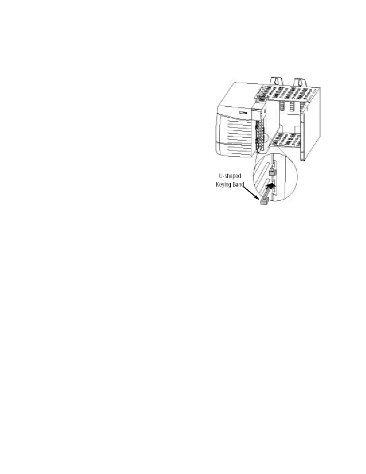
Figure 2.1 (Module insertion into a rack)
2. Key the RTB in positions that correspond to unkeyed module
positions. Insert the wedge-shaped tab on the RTB with the rounded
edge first. Push the tab onto the RTB until it stops.
Keying the Removable Terminal Block
Key the RTB to prevent inadvertently connecting the incorrect RTB to
your module.
When the RTB mounts onto the module, keying positions will match up.
For example, if you place a U-shaped keying band in position #4 on the
module, you cannot place a wedge-shaped tab in #4 on the RTB or your
RTB will not mount on the module.
We recommend that you use a unique keying pattern for each slot in the
chassis.
Page 26
12 ControlLogix™ Analog HART Modules
1. Insert the U-shaped band with the longer side near the terminals. Push
the band onto the module until it snaps into place.
Figure 2.2 (Terminal block diagram with keying)
Wiring Your Module
Follow these guidelines to wire your input signal cables:
• Power, input, and output (I/O) wiring must be in accordance with
Class 1, Division 2 wiring methods [Article 501-4(b) of the National
Electrical Code, NFPA 70] and in accordance with the authority
having jurisdiction.
• Peripheral equipment must be suitable for the location in which it is
used.
• Route the field wiring away from any other wiring and as far as
possible from sources of electrical noise, such as motors,
transformers, contactors, and ac devices. As a general rule, allow at
least 6 in. (about 15.2 cm) of separation for every 120 V of power.
• Routing the field wiring in a grounded conduit can reduce electrical
noise further.
• If the field wiring must cross ac or power cables, ensure that they
cross at right angles.
• To limit the pickup of electrical noise keep signal wires as far from
power and load lines as possible.
• For improved immunity to electrical noise, use Belden 8761 (shielded,
twisted pair) or equivalent wire for millivolt sensors
Page 27

Preparing and Wiring
the Cables
Chapter 2: Installing And Wiring Your Module 13
• Ground the shield drain wire at only one end of the cable. The
preferred location is at the shield connections at the ControlLogix
chassis. (Refer to IEEE Std. 518, Section 6.4.2.7 or contact your
sensor manufacturer for additional details.)
• Keep all unshielded wires as short as possible.
• To limit overall cable impedance, keep input cables as short as
possible. Locate your I/O chassis as near to the sensors as your
application will permit.
• Tighten screw terminals with care. Excessive tightening can strip a
screw.
• Follow system grounding and wiring guidelines found in your
ControlLogix Installation and Operation Manual.
To prepare and connect cable leads and drain wires, follow these steps:
1. At each end of the cable, strip some casing to expose individual wires.
2. Trim signal wires to 5-inch lengths beyond the cable casing. Strip
about 3/16 inch (4.76 mm) of insulation to expose the ends of the
wires.
3. At the module-end of the cables (see figure above):
- extract the drain wire and signal wires
- remove the foil shield
- bundle the input cables with a cable strap
4. Connect pairs of drain wires together, Channels 0 and 1, Channels 2
and 3, Channels 4 and 5, Channels 6 and 7. Keep drain wires as short
as possible.
5. Connect the drain wires to the grounding lug on the PLC chassis.
6. Connect the signal wires of each channel to the terminal block.
Important: Only after verifying that your connections are correct for
each channel, trim the lengths to keep them short. Avoid cutting leads
too short.
7. At the source-end of cables from voltage devices:
- remove the drain wire and foil shield
- apply shrink wrap as an option
Page 28

14 ControlLogix™ Analog HART Modules
- connect to devices keeping the leads short
Important: If noise persists, try grounding the opposite end of the cable,
instead (Ground one end only.)
Terminal Block Layout
The following figure shows the general terminal block layout. The input
signal type will determine which pins are used.
IN0+
IN0-
IN1+
IN1-
RTN
IN2+
IN2-
IN3+
IN3-
IN4+
IN4-
IN5+
IN5-
RTN
IN6+
IN6-
IN7+
IN7-
2
1
4
6
8
10
12
14
16
18
20
22
24
26
28
30
32
34
36
I RTN-0
3
NC
5
I RTN-1
7
NC
9
RTN
11
I RTN-2
13
NC
15
I RTN-3
17
NC
I RTN-4
19
NC
21
23
I RTN-5
NC
25
RTN
27
29
I RTN-6
31
NC
I RTN-7
33
NC
35
VOUT-4
IOUT-4
RTN
VOUT-5
IOUT-5
VOUT-6
IOUT-6
RTN
VOUT-7
IOUT-7
1
2
4
6
8
10
12
14
16
18
20
VOUT-0
3
IOUT-0
5
RTN
7
VOUT-1
9
IOUT-1
11
VOUT-2
13
IOUT-2
15
RTN
17
VOUT-3
19
IOUT-3
Wiring Inputs to the
IF8H Module
Voltage Inputs - Voltage inputs use the terminal block pins labelled IN+#
and IN-#.
Voltage Input
+V
- V
IN0+
IN0-
IN1+
IN1-
RTN
IN2+
IN2-
IN3+
IN3-
IN4+
IN4-
IN5+
IN5-
RTN
IN6+
IN6-
IN7+
IN7-
1
2
4
6
8
10
12
14
16
18
20
22
24
26
28
30
32
34
36
I RTN-0
3
NC
5
I RTN-1
7
NC
RTN
9
11
I RTN-2
13
NC
15
I RTN-3
17
NC
19
I RTN-4
21
NC
23
I RTN-5
25
NC
27
RTN
29
I RTN-6
31
NC
33
I RTN-7
35
NC
Note: All terminals marked RTN are connected internally.
Page 29
Chapter 2: Installing And Wiring Your Module 15
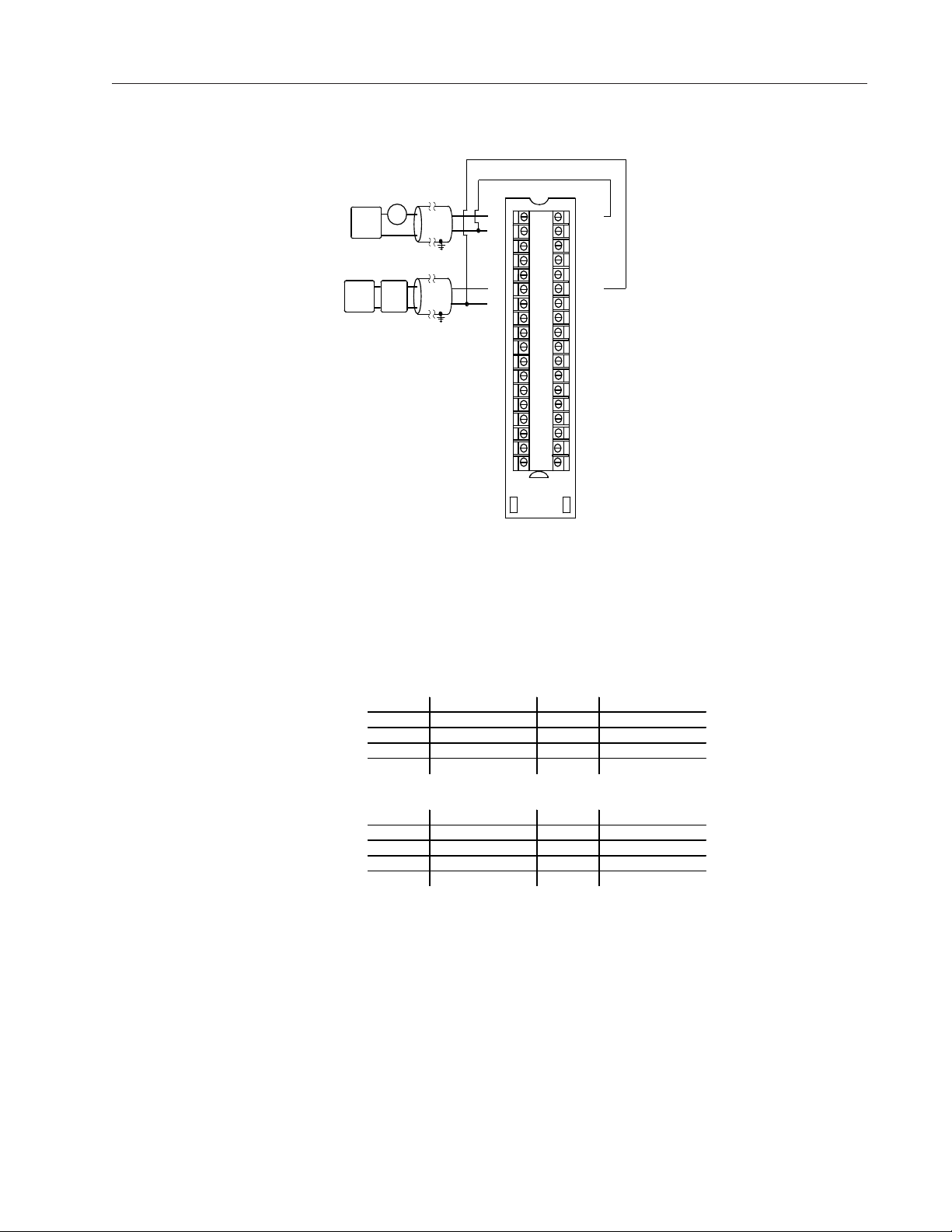
Current Inputs - Current inputs use the terminal block pins labelled IN+#,
IN-#, and I RTN-#. Note that HART communication is only active with
current inputs.
2 Wire Current Input
2 Wire
XMTR
+ -
+
24V DC
Power
Supply
-
4 Wire Current Input
+
+
24V D C
4 Wire
Power
XMTR
Supply
-
--
IN0+
IN0-
IN1+
IN1-
RTN
+
IN2+
IN2-
IN3+
IN3-
IN4+
IN4-
IN5+
IN5-
RTN
IN6+
IN6-
IN7+
IN7-
1
2
I RTN-0
3
4
NC
5
6
I RTN-1
7
8
NC
9
10
12
14
16
18
20
22
24
26
28
30
32
34
36
RTN
11
I RTN-2
13
NC
15
I RTN-3
17
NC
19
I RTN-4
21
NC
23
I RTN-5
25
NC
27
RTN
29
I RTN-6
31
NC
33
I RTN-7
35
NC
Note: All terminal s ma rked RTN are connected internally.
Note: When using current inputs, if multiple (-) terminals are connected
together, the channel to channel isolation will be compromised (i.e. this
would be considered a single ended wiring configuration). If a single
ended wiring configuration is to be utilized, the (-) terminals should also
be connected to the RTN to maintain module accuracy.
Differential Current
Channel Terminals Channel Terminals
Channel 0 IN0+, IN0-, iRTN0 Channel 4 IN4+, IN4-, iRTN4
Channel 1 IN1+, IN1-, iRTN1 Channel 5 IN5+, IN5-, iRTN5
Channel 2 IN2+, IN2-, iRTN2 Channel 6 IN6+, IN6-, iRTN6
Channel 3 IN3+, IN3-, iRTN3 Channel 7 IN7+, IN7-, iRTN7
Differential Voltage
Channel Terminals Channel Terminals
Channel 0 IN0+, IN0- Channel 4 IN4+, IN4Channel 1 IN1+, IN1- Channel 5 IN5+, IN5Channel 2 IN2+, IN2- Channel 6 IN6+, IN6Channel 3 IN3+, IN3- Channel 7 IN7+, IN7-
Page 30
16 ControlLogix™ Analog HART Modules
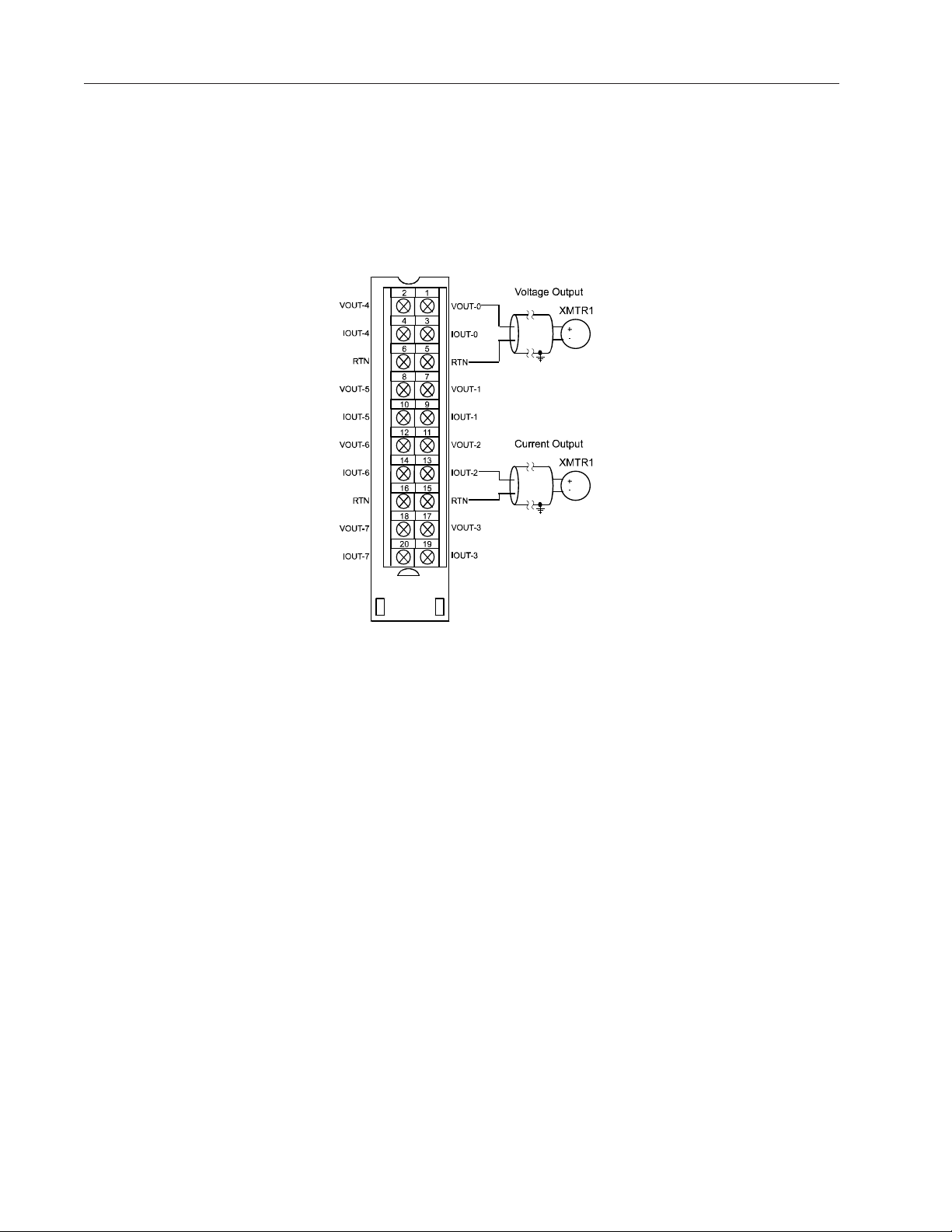
Wiring Outputs to the
OF8H Module
The OF8H module supports voltage and current outputs.
Voltage Outputs - Voltage outputs use the terminal block pins labelled
VOUT-# and RTN
Current Outputs - Current outputs use the terminal block pins labelled
IOUT-# and RTN
Note: HART communication is only active with current outputs.
Page 31

Chapter 2: Installing And Wiring Your Module 17
This page intensionally left blank.
Page 32

18 ControlLogix™ Analog HART Modules
Page 33

Ownership and
Connections
Chapter 3Chapter 3
Chapter 3
Chapter 3Chapter 3
Operation Within the
ControlLogix System
This chapter describes how the 1756sc-IF8H and 1756sc-OF8H analog
HART modules work within the ControlLogix system. This chapter
covers:
• Ownership and connections to the module
• Direct connections
• Listen only mode
• Configuration changes with multiple owners.
Every I/O module in the ControlLogix system must be owned by a
Logix5550 Controller to be useful. This owner-controller stores
configuration data for every module that it owns and can be local or
remote in regard to the I/O module’s position. The owner sends the I/O
module configuration data to define the module’s behavior and begin
operation within the control system. Each ControlLogix I/O module
must continuously maintain communication with its owner to operate
normally.
Using RSNetWorx
and RSLogix 5000
Typically, each module in the system will have only 1 owner. Input
modules can have more than 1 owner. Output modules, however, are
limited to a single owner.
The I/O configuration portion of RSLogix5000 generates the
configuration data for each I/O module in the control system, whether
the module is located in a local or remote chassis. A remote chassis,
also known as networked, contains the I/O module but not the
module’s owner controller. Configuration data is transferred to the
controller during the program download and subsequently transferred
to the appropriate I/O modules. I/O modules in the same chassis as the
controller are ready to run as soon as the configuration data has been
downloaded. You must run RSNetWorx to enable I/O modules in the
networked chassis.
Running RSNetWorx transfers configuration data to networked modules
and establishes a Network Update Time (NUT) for ControlNet that is
compliant with the desired communications options specified for each
module during configuration. If you are not using I/O modules in a
networked chassis, running RSNetWorx is not necessary. However,
anytime a controller references an I/O module in a networked chassis,
Page 34

RSNetWorx must be run to configure ControlNet. Follow these general
guidelines when configuring I/O modules:
1. Configure all I/O modules for a given controller using RSLogix 5000
and download that information to the controller.
2. If the I/O configuration data references a module in a remote chassis,
run RSNetWorx.
Important: RSNetWorx must be run whenever a new module is added
to a networked chassis. When a module is permanently removed from a
remote chassis, we recommend that RSNetWorx be run to optimize the
allocation of network bandwidth.
Direct Connections
Module Operation
A direct connection is a real-time data transfer link between the
controller and the device that occupies the slot that the configuration
data references. When module configuration data is downloaded to an
owner-controller, the controller attempts to establish a direct
connection to each of the modules referenced by the data.
If a controller has configuration data referencing a slot in the control
system, the controller periodically checks for the presence of a device
there. When a device’s presence is detected, the controller
automatically sends the configuration data. If the data is appropriate to
the module found in the slot, a connection is made and operation
begins. If the configuration data is not appropriate, the data is rejected
and an error message displays in the software. In this case, the
configuration data can be inappropriate for any of a number of
reasons.
The controller maintains and monitors its connection with a module.
Any break in the connection, such as removal of the module from the
chassis while under power, causes the controller to set fault status bits
in the data area associated with the module. The RSLogix 5000
software may monitor this data area to announce the modules’ failures.
In traditional I/O systems, controllers poll input modules to obtain
their input status. Analog input modules in the ControlLogix system
are not polled by a controller once a connection is established. The
modules multicast their data periodically. Multicast frequency depends
on the options chosen during configuration and where in the control
system that input module physically resides. An input module’s
communication, or multicasting, behavior varies depending upon
whether it operates in the local chassis or in a remote chassis. The
following sections detail the differences in data transfers between
these set-ups.
Page 35

Modules in a Local
Chassis
Chapter 3: Operation within the System 21
When a module resides in the same chassis as the owner controller, the
following two configuration parameters will affect how and when the
input module multicasts data:
· Real Time Sample (RTS) configured via Real Time Sample tag.
· Requested Packet Interval (RPI) configured via I/O module properties.
Real Time Sample (RTS)
This configurable parameter instructs the module to perform the
following operations:
1. scan all of its input channels and store the data into on-board
memory
2. multicast the updated channel data (as well as other status data) to
the backplane of the local chassis
Requested Packet
Interval (RPI)
This configurable parameter also instructs the module to multicast its
channel and status data to the local chassis backplane.
The RPI instructs the module to multicast the current contents of its
on-board memory when the RPI expires, (i.e. the module does not
update its channels prior to the multicast).
Important: The RPI value is set during the initial module
configuration using RSLogix 5000.
It is important to note that the module will reset the RPI timer each
time an RTS is performed. This operation dictates how and when the
owner controller in the local chassis will receive updated channel data,
depending on the values given to these parameters. If the RTS value is
less than or equal to the RPI, each multicast of data from the module
will have updated channel information. In effect, the module is only
multicasting at the RTS rate.
If the RTS value is greater than the RPI, the module will multicast at
both the RTS rate and the RPI rate. Their respective values will dictate
how often the owner controller will receive data and how many
multicasts from the module contain updated channel data. Note: Even
though data may be transferred at the RPI rate, the data will be
identical to the previous RTS data transfer. HART data can change.
Setting the RPI < 100 msec will allow you to see all changes.
Page 36

22 ControlLogix™ Analog HART Modules
Modules in a Remote
Chassis
If an input module resides in a networked chassis, the role of the RPI
and the module’s RTS behavior change slightly with respect to getting
data to the owner. The RPI and RTS intervals still define when the
module will multicast data within its own chassis (as described in the
previous section), but only the value of the RPI determines how often
the owner controller will receive it over the network.
When an RPI value is specified for an input module in a remote chassis,
in addition to instructing the module to multicast data within its own
chassis, the RPI also “reserves” a spot in the stream of data flowing
across the ControlNet network.
The timing of this “reserved” spot may or may not coincide with the
exact value of the RPI, but the control system will guarantee that the
owner controller will receive data at least as often as the specified
RPI.
The “reserved” spot on the network and the module’s RTS are
asynchronous to each other. This means there are Best and Worst Case
scenarios as to when the owner controller will receive updated channel
data from the module in a networked chassis.
Listen-Only Mode
Best Case RTS Scenario
In the Best Case scenario, the module performs an RTS multicast with
updated channel data just before the “reserved” network slot is made
available. In this case, the remotely located owner receives the data
almost immediately.
Worst Case RTS Scenario
In the Worst Case scenario, the module performs an RTS multicast just
after the “reserved” network slot has passed. In this case, the ownercontroller will not receive data until the next scheduled network slot.
Because it is the RPI and NOT the RTS which dictates when the
module’s data will be sent over the network, we recommend the RPI
value be set LESS THAN OR EQUAL TO the RTS to make sure that
updated channel data is received by the owner controller with each
receipt of data.
Any controller in the system can listen to the data from any I/O
module (e.g. input data or “echoed” output data) even if the controller
does not own the module (i.e. it does not have to hold the module’s
configuration data to listen to the module).
The “listen only” mode is set during the I/O configuration process.
Choosing a ‘Listen-Only’ mode option allows the controller and
module to establish communications without the controller sending
Page 37

Multiple Owners of
Input Modules
Chapter 3: Operation within the System 23
any configuration data. In this instance, another controller owns the
module being listened to.
Important: Controllers using the Listen-Only mode continue to receive
data multicast from the I/O module as long as a connection between an
owner and I/O module is maintained. If the connection between all
owners and the module is broken, the module stops multicasting data and
connections to all ‘Listening controllers’ are also broken.
Because ‘Listening controllers’ lose their connections to modules
when communications with the owner stop, the ControlLogix system
will allow you to define more than one owner for input modules.
Important: Only input modules can have multiple owners. If multiple
owners are connected to the same input module, they must maintain
identical configuration for that module.
In the example below, Controller A and Controller B have both been
configured to be the owner of the input module.
When the controllers begin downloading configuration data, both try
to establish a connection with the input module. Whichever
controller’s data arrives first establishes a connection. When the
second controller’s data arrives, the module compares it to its current
configuration data (the data received and accepted from the first
controller).
If the configuration data sent by the second controller matches the
configuration data sent by the first controller the connection is also
accepted. If any parameter of the second configuration data is different
from the first, the module rejects the connection and the user is
informed by an error in the software.
The advantage of multiple owners over a ‘Listen-only’ connection is
that now either of the controllers can lose the connection to the module
and the module will continue to operate and multicast data to the
system because of the connection maintained by the other owner
controller.
Note: The previous discussion of multiple owners assumes the
configuration tag “.configrevnumber” is set to 1. Operation differs is
the tag is set to 0. Refer to Chapter 5 for descriptions of this tag’s
settings.
Page 38

24 ControlLogix™ Analog HART Modules
Configuration
Changes in an Input
Module with Multiple
Owners
You must be careful when changing an input module’s configuration data
in a multiple owner scenario. When the configuration data is changed in
one of the owners, for example, Controller A, and sent to the module,
that configuration data is accepted as the new configuration for the
module. Controller B will continue to listen, unaware that any changes
have been made in the module’s behavior.
Important: When changing configuration for a module with multiple
owners, we recommend the connection be inhibited. To prevent other
owners from receiving potentially erroneous data, as described above,
the following steps must be followed when changing a module’s
configuration in a multiple owner scenario when on-line:
1. For each owner controller, inhibit the controller’s connection to the
module in the software on the I/O Module Connection tab.
2. Make the appropriate configuration data changes in the software.
3. Repeat steps 1 and 2 for all owner controllers, making the exact
same changes in all controllers.
4. Uncheck the Inhibit box in each owner’s configuration to reconnect
each module.
Page 39

Chapter 4
Configuring RSLogix 5000 For The IF8H
and OF8H
This chapter explains how to incorporate your module into the
ControlLogix system. It also covers a brief overview of the configuration,
input and output (OF8H only) tags Topics discussed include:
• Adding your module to a RSLogix 5000 project
• Configuration tags overview
• Input tags overview
• Output tags overview
Module Installation
Adding Your Module
to a Project
The process of incorporating your HART module into the ControlLogix
system is similar to the process needed to add an Allen-Bradley module.
You will use your RSLogix 5000 programming software to install and
configure your HART module. The module is not currently in the
RSLogix 5000 I/O pick list, so you will need to copy and paste information
from a sample project that can be obtained from our website at
(www.spectrumcontrols.com). You may also choose to build onto the
sample project itself. The sample project contains the module profile,
configuration tags, input tags, and ladder samples needed to configure
each HART module.
The module has a unique set of tag definitions which are used to configure
specific features. Chapter 5 and 6, Channel Configuration, Data, and
Status, gives you detailed information about available configuration settings
and status information. These values are set using your programming
Page 40

26 ControlLogix™ Analog HART Modules
software and ladder logic. Before you can use these features you must
first include the module into the project.
1.
Download and open the sample project from our website at
www.spectrumcontrols.com It contains information for the IF8H and
OF8H. Open your project. Drag and drop the IF8H or OF8H module into
the I/O configuration section of your project.
a) Open the sample project.
b) Open your new project.
c) Click once on the IF8H or OF8H in the IO configurator.
d) Drag and drop it into the I/O Configurator section of your project.
Note: You may need to change the slot number of the module after
pasting it into your project.
Note: If only one of the HART modules is to be utilized, copy the profile,
tags and ladder for that module only.
Page 41

Chapter 4: Programming Your Module 27
See Appendix C for more details regarding module profile settings.
2.
Drag and drop the IF8H or OF8H user-defined data types from the
sample project into your project.
There are eleven user defined data types that need to be moved.
•
GetDeviceInfo
•
If8hConfigurationBlock
•
Of8hConfigurationBlock
•
If8hInputBlock
•
Of8hInputBlock
•
Of8hOutputBlock
•
Packet0
•
Packet1
•
Packet2
•
Packet3
•
Packet4
Page 42

28 ControlLogix™ Analog HART Modules
a) Click on the data type
b) Drag it into your new project.
c) Continue to drag and drop the data types until all have been moved.
Note: These can only be moved one at a time.
3.
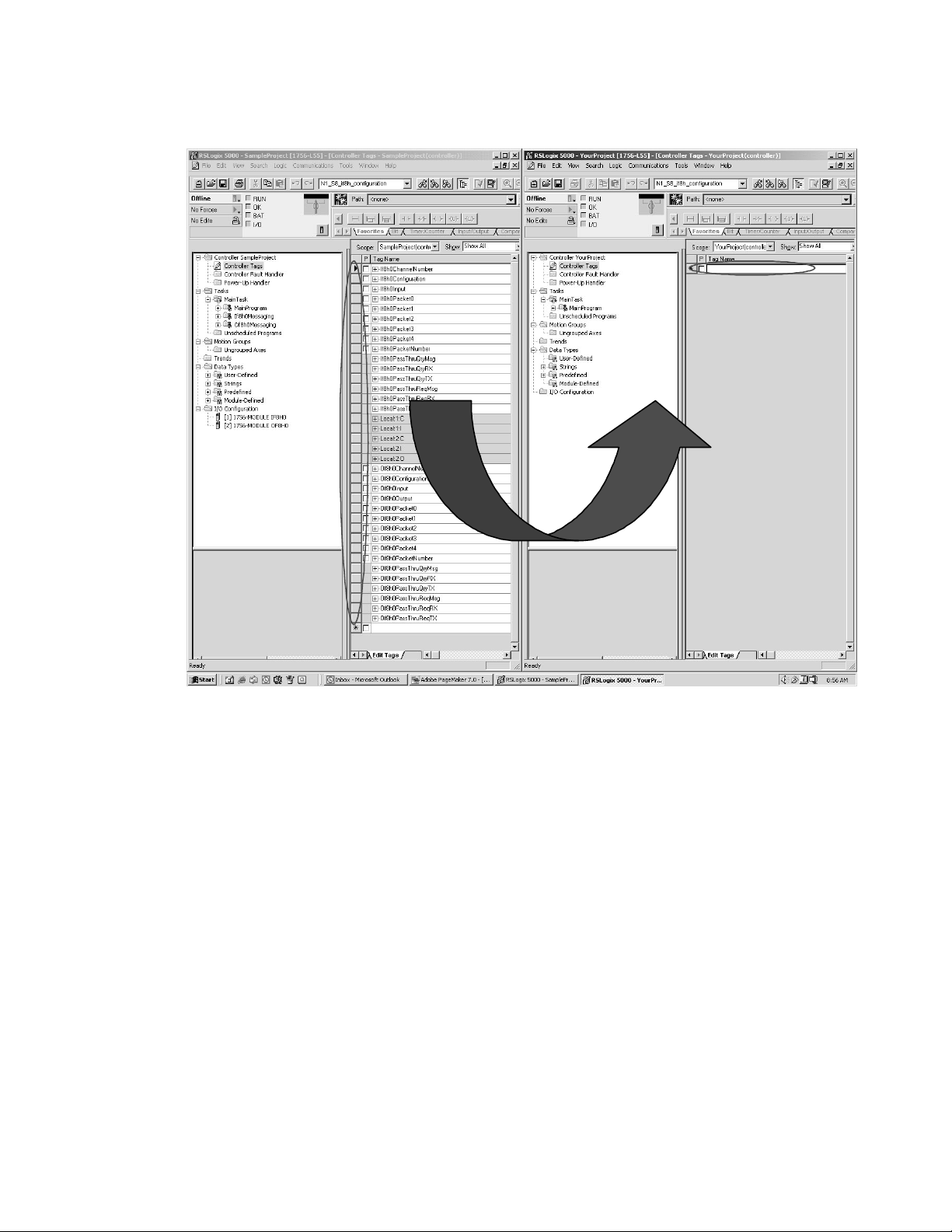
Drag and drop the controller tags from the sample project into your
project.
a) Right click on the Controller Tags item of the sample project and select
edit.
b) Right click on the Controller Tags item of your project and select edit.
c) Scroll down to the Controller tags of the sample project and select all
the tags by highlighting them. Be sure to select the tags by using the
gray buttons to the left of the tag name. See figure below.
Page 43
Chapter 4: Programming Your Module 29
d) Paste the tags into your project. Be sure to paste the tags in the empty
field marked with an asterisk. Refer to the figure above.
Note: If you are sending HART messages to the module, you will need
to copy the If8h0Messaging program and or the Of8h0Messaging
program. You will also need to copy the associated program tags for each
routine. Use the procedure in step 3 for copying the program tags to your
project.
Note: If8h0Configuration / If8h0Input and Of8h0Configuration /
Of8h0Input contain the configuration, data and status tags for the modules.
The other tags are used for performing various functions to your module
via ladder logic.
Note: Certain tag names include a zero succeeding the catalog number;
for example, If8h0Configuration contains a zero. The zero is used to
identify the module if there’s more than one IF8H module in the system.
This number could also be used to imply the slot number of the module.
The user can omit this number or change the tag name if need be.
Note: Be sure all tags are displayed before moving them. Select Display
All from the Edit drop down window.
Page 44

30 ControlLogix™ Analog HART Modules
Note: The “Local:e:I” and “Local:e:C” tags are not copied.
4.
Create a new ladder logic routine in your project.
a) In your project, double click on the MainRoutine.
b) Double click on the MainRoutine item in the sample project to display
the ladder logic.
c) Left mouse inside the MainProgram ladder logic in the sample project
and press crtl-A to select all the rungs.
d) Drag and drop these rungs over and add them to the MainRoutine in
your project.
Note: You will need to delete the one blank “solid bar” rung either at the
top or bottom of the routine which was left over when you double clicked
on the empty MainRoutine in your project.
Page 45

Configuration Tags
Overview
Chapter 4: Programming Your Module 31
e) Drag and drop the routines IF8H0_Packet_Data and
OF8H0_Packet_Data to the MainProgram in your project.
Note: You may choose to omit pasting the OF8H0_Packet_Data routine
if you are not using the OF8H module in your system.
f) Now add JSR ladder instructions in your MainRountine which calls the
two routines in step e.
Note: RSLogix 5000 will verify the ladder logic sample. You may receive
errors regarding invalid tags. You will need to change the slot addressing
in the logic to coordinate with the location of the module.
This completes the installation of the module in the system
The configuration tags for the IF8H and OF8H that were copied in step 3
are used to change the operation settings, including input type, filterfrequency, scaling, etc. The data contained in these tags are then copied
to both the IF8H and OF8H local configuration tags by the ladder in step
4. When using generic profiles, the local module tags that are created are
made up of a single dimensional array with only one data type allowed,
usually a DINT. Therefore, the process of copying the defined
configuration tags to the local configuration tags is required in order to
parse the data. Specific information regarding tag settings may be found
in Chapter 5.
Note: The local configuration tags (i.e Local:e:C) mentioned above are
automatically created when the module was copied from the sample
project in step 1.
Note: The defined configuration tags (If8h0Configuration) are copied to
the local configuration tags (Local:e:C) by the ladder in step 4.
Page 46

32 ControlLogix™ Analog HART Modules
1756sc-IF8H (If8h0Configuration)
Page 47

Chapter 4: Programming Your Module 33
1756sc-OF8H (Of8h0Configuration)
Page 48
34 ControlLogix™ Analog HART Modules
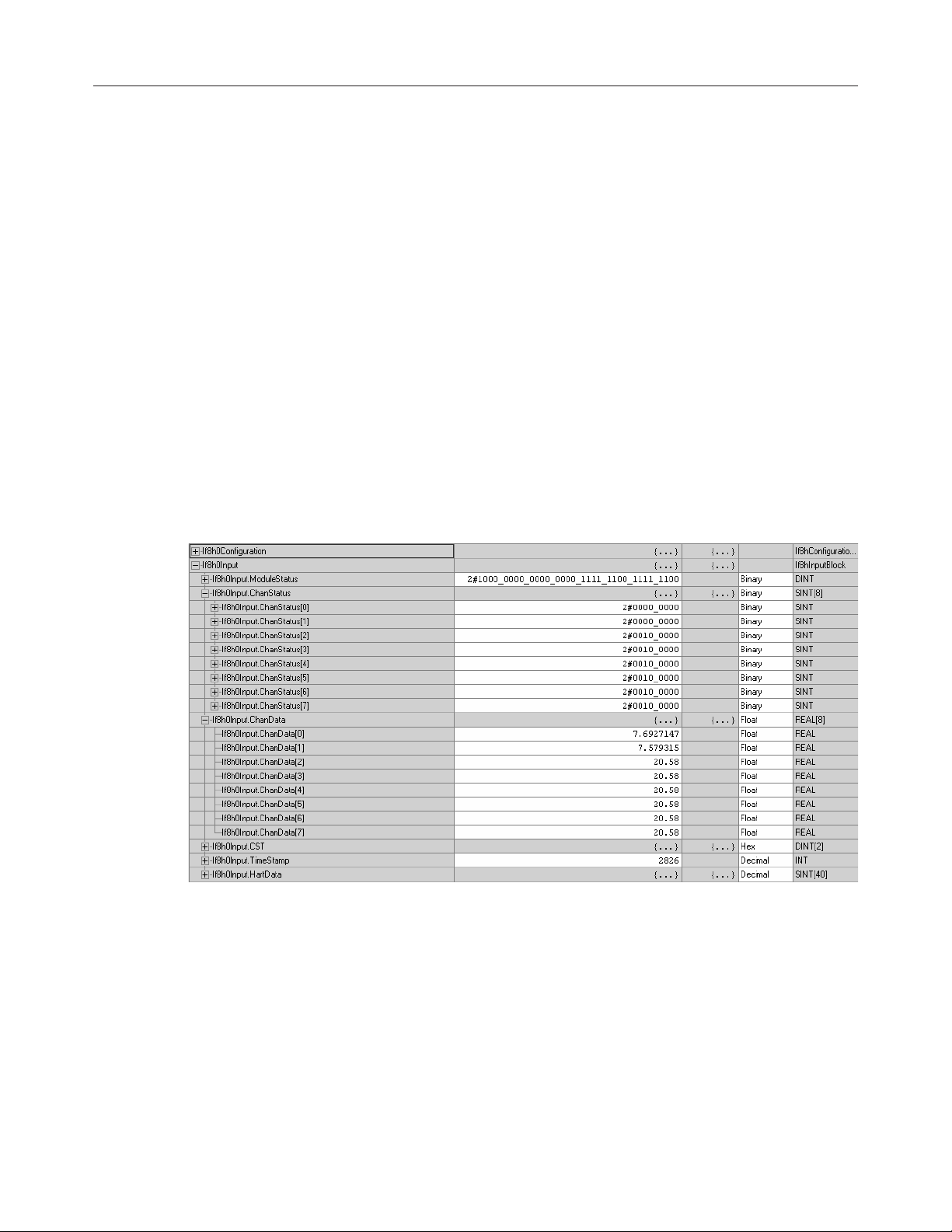
Input Tags Overview
The input tags contain the analog data, status, and HART data. As in the
case of the configuration tags, the input tags are also copied to the local
input tags for the module. For details regarding the analog data and status
refer to Chapter 5. For details regarding the HART data refer to Chapter
7.
Note: The local input tags (i.e. Local:e:I) mentioned above are
automatically created when the module was copied from the sample
project in step 1.
Note: The defined configuration tags (If8h0Input) are copied to the local
input tags (Local:e:I) by the ladder in step 4.
Note: The HART data found in the input tags has not been demultiplexed.
In other words, the data is changing dynamically depending on what
channel and which HART packet is currently being scanned. Please refer
to chapter 7 for more details regarding demultiplexing of the HART data.
1756sc-IF8H (If8h0Input)
Page 49

Chapter 4: Programming Your Module 35
1756sc-OF8H (Of8hInput)
Output Tags
Overview
(OF8H Only)
The output tags are used to control the output voltage or current level,
depending on the configuration settings, of each individual channel.
Note: The local output tags (i.e. Local:e:O) are automatically created
when the module was copied from the sample project in step 1.
Note: The defined output tags (Of8h0Output) are copied to the local
output tags (Local:e:O) by the ladder in step 4.
Page 50

36 ControlLogix™ Analog HART Modules
Page 51

Chapter 5: 1756sc-IF8H Channel Configuration, Data, and Status 37
Configuration, Data,Configuration, Data,
Configuration, Data,
Configuration, Data,Configuration, Data,
Chapter 5
and Staand Sta
and Sta
and Staand Sta
for the 1756sc-IF8Hfor the 1756sc-IF8H
for the 1756sc-IF8H
for the 1756sc-IF8Hfor the 1756sc-IF8H
Read this chapter to:
•
Send configuration data to the module
• Configuration tags
•
Module filter selection
• Module input tags
• Accessing the module tags
•
Changing configuration information at the tags
This chapter outlines the detailed settings for the 1756sc-IF8H. These
settings determine the modules input types, filter frequencies, scan rates,
and various attributes. Detailed descriptions of these settings are available
in the Tag Definition section of this chapter.
tus tus
tus
tus tus
TT
T
TT
aa
a
aa
gsgs
gs
gsgs
SendSend
Send
SendSend
ConfigurationConfiguration
Configuration
ConfigurationConfiguration
Data to theData to the
Data to the
Data to theData to the
ModuleModule
Module
ModuleModule
Note: The following format is used to describe tags
Tag Name Data Type Style Description
After changing the configuration tags in this chapter you must then send
them to the module. To do this you may perform any of these operations:
1. Inhibit then un-inhibit the module via the module properties dialog,
Connection Tab
2. Reset the module via the modules properties dialog. Module Info tab.
3. Reset the module via ladder logic. See the “DoReset” rung in the
sample ladder located in Chapter 8.
4. Perform a “Set Attribute All” or Module Reconfigure message
instruction via ladder logic. Refer to Chapter 8 for information about the
“DoSetAttrAll” command.
Note: If an invalid configuration is sent to the module a connection error
will occur. See chapter 9 for a list of error codes.
Page 52

38 ControlLogix™ Analog HART Modules
ConfigurationConfiguration
Configuration
ConfigurationConfiguration
TT
aa
gs fgs f
T
a
gs f
TT
aa
gs fgs f
1756sc-IF8H1756sc-IF8H
1756sc-IF8H
1756sc-IF8H1756sc-IF8H
or theor the
or the
or theor the
The following tags allow for custom configuration of the module. These
tags can be found within the controller scope under the tag name
If8h0Configuration.
Tag Name Data Type Style Description
If8h0Configuration If8hConfigurationBlock NA Module configuration
If8h0Configuration.ConfigRevision SINT DEC Controls mult iple owner connections.
If8h0Configuration.AdcFilter SINT DEC 0 = 10Hz 4 = 250Hz
If8h0Configuration.RTS INT DEC The time in millis econds that updated
1
If8h0Configuration.ChXConfigBits
If8h0Configuration.ChXConfigBits.0
If8h0Configuration.ChXConfigBits.1
If8h0Configuration.ChXConfigBits.2
If8h0Configuration.ChXConfigBits.3
If8h0Configuration.ChXConfigBits.4
If8h0Configuration.ChXConfigBits.5
If8h0Configuration.ChXConfigBits.6
If8h0Configuration.ChXConfigBits.7
1
X repres ents the module channel number (0 to 7).
SINT BIN Channel c onfiguration settings
1
BOOL DEC Unused
1
BOOL DEC Unused
1
BOOL DEC Unused
1
BOOL DEC Unused
1
BOOL DEC Enables lat ching for the rate alarm.
1
BOOL DEC Enables latching for all four process
1
BOOL DEC Disable alarms
1
BOOL DEC Enable HART Communication
Table 5.1a
0 = Always connect, overwrite w/new
configuration.
1 = Only connect if configuration
matches existing configuration.
1 = 50Hz 5 = 1000Hz
2 = 60Hz 6 = 20Hz
3 = 100Hz 7 = 15Hz
input data is to be sent from the
module to the controller.
18 to 10000 msec
Set to zero
Set to zero
Set to zero
Set to zero
Latching causes the rate alarm to
remain set until an unlatch service is
explic itly sent to the channel or
alarm.
0 = Rate alarm unlatched
1 = Rate alarm latched
alarms: low, low low, high, high high.
Latching causes the process alarm to
remain set until an unlatch service is
explic itly sent to the channel or
alarm.
0 = Alarms unlatched
1 = Alarms lat ched
0 = Enabled
1 = Di sabled
0 = Di sabled
1 = Enabled
Page 53

Chapter 5: 1756sc-IF8H Channel Configuration, Data, and Status 39
Table 5.1b
Tag Name Data Type Style Description
1
If8h0Configuration.ChXInputRange
SINT DEC Configures the channel's input range.
Input ranges include:
0 = -10.25 to 10.25V
1 = 0 to 5.125V
2 = 0 to 10.25V
3 = 0 to 20.58 mA
4 = 3.42 mA to 20.58 mA
1
If8h0Configuration.ChXDigitalFilter
INT DEC A non-zero value enables the filter,
providing a time constant in
milliseconds used in a first order lag
filter to smooth the input signal. If nonzero, must be greater than twice the
RTS rate.
0 to 20100 msec
1
If8h0Configuration.ChXRateAlarmLimit
REAL FLOAT The trigger point for the rate alarm
status bit which will set if the input
signal changes at a rate faster than the
configured rate alarm. Configured in
user sc aling units per second.
If8h0Configuration.ChXLowSignal
1
REAL FLOAT One of four points used in scaling. The
low signal represents the minimum
input range.
If8h0Configuration.ChXHighSignal
1
REAL FLOAT One of four points used in scaling. The
high signal represents the maximum
input range.
1
If8h0Configuration.ChXLowEngineering
REAL FLOAT One of four points used in scaling. The
low engineering represents the
minimum sc aled range.
1
If8h0Configuration.ChXHighEngineering
REAL FLOAT One of four points used in scaling. The
high engineering represents the
maximum scaled range.
If8h0Configuration.ChXLowAlarm
1
REAL FLOAT The low process alarm trigger point.
Enter the value in terms of engineering
units.
If8h0Configuration.ChXHighAlarm
1
REAL FLOAT The high process alarm trigger point.
Enter the value in terms of engineering
units.
1
If8h0Configuration.ChXLowLowAlarm
REAL FLOAT The low low process alarm trigger point.
Enter the value in terms of engineering
units.
1
X represents the module channel number (0 to 7).
Page 54

40 ControlLogix™ Analog HART Modules
Table 5.1c
Tag Name Data Type Style Description
If8h0Configuration.ChXHighHighAlarm
1
REAL FLOAT The high high process alarm trigger
point. Enter the value in terms of
engineering units.
If8h0Configuration.ChXAlarmDeadband
1
REAL FLOAT Forms a deadband around the process
alarms which causes the
corresponding process alarm status
bit to remain set until the input moves
beyond the trigger point by greater
than the amount of the alarm
deadband.
If8h0Configuration.ChXCalBias
1
REAL FLOAT
Offset to add to channel analog value
If8h0Configuration.HandleTimeout INT DEC There is a handle timeout associat ed
with the final reply message. After the
module obtaines the requested
information from the HART devic e, it
will start the HandleTimeout timer
(duration defined by the
HandleTimeout tag). The replay
message will be kept in memory
during the HandleTimeout period.
After the timeout occurs or after the
message is retrieved by the passthrough response query command, the
storage buffer will be discarded, and
another pass through message will be
serviced without being rejected.
HandleTimeout is in the range of 1 to
255 seconds .
If8h0Configuration.ModuleConfigBits INT BIN Module function settings
If8h0Configuration.ModuleConfigBits.0 BOOL DEC Reserved set to zero
If8h0Configuration.ModuleConfigBits.1 BOOL DEC Reserved set to zero
If8h0Configuration.ModuleConfigBits.2 BOOL DEC Reserved set to zero
If8h0Configuration.ModuleConfigBits.3 BOOL DEC Reserved set to zero
If8h0Configuration.ModuleConfigBits.4 BOOL DEC Reserved set to zero
If8h0Configuration.ModuleConfigBits.5 BOOL DEC Reserved set to zero
If8h0Configuration.ModuleConfigBits.6 BOOL DEC Reserved set to zero
If8h0Configuration.ModuleConfigBits.7 BOOL DEC Reserved set to zero
If8h0Configuration.ModuleConfigBits.8 BOOL DEC Reserved set to zero
If8h0Configuration.ModuleConfigBits.9 BOOL DEC Reserved set to zero
If8h0Configuration.ModuleConfigBits.10 BOOL DEC Reserved set to zero
If8h0Configuration.ModuleConfigBits.11 BOOL DEC Reserved set to zero
If8h0Configuration.ModuleConfigBits.12 BOOL DEC Reserved set to zero
If8h0Configuration.ModuleConfigBits.13 BOOL DEC Reserved set to zero
1
X represents the module channel number (0 to 7).
Page 55

Chapter 5: 1756sc-IF8H Channel Configuration, Data, and Status 41
Table 5.1d
Tag Name Data Type Style Description
If8h0Configuration.ModuleConfigBits.14
If8h0Configuration.ModuleConfigBits.15
2
The configuration of bits 14 and 15 directly eff ect the update time of the HART data acquisition for the module, f or example if
bit 15 is set, the HART update time for each channel w ill be doubled.
2
2
BOOL DEC Bits 14 and 15 determine how often
the pass-through command is serviced
by the module.
15,14 = 00 = pass-through serviced
once per two channels scanned
15,14 = 01 = pass-through serviced
once per module scan
15,14 = 1X = pass-through serviced
once per channel scan
BOOL DEC Bits 14 and 15 determine how often
the pass-through command is serviced
by the module.
15,14 = 00 = pass-through serviced
once per two channels scanned
15,14 = 01 = pass-through serviced
once per module scan
15,14 = 1X = pass-through serviced
once per channel scan
Module FilterModule Filter
Module Filter
Module FilterModule Filter
SelectionSelection
Selection
SelectionSelection
Module Update TimeModule Update Time
Module Update Time
Module Update TimeModule Update Time
The module update time is defined as the time required for the module to
sample and convert the input signals of all enabled input channels and
make the resulting data values available to the processor. The update time
is influenced by the input type and filter frequency configuration settings.
The following table shows associated time adders based on frequency
selection.
Filter Update Time
10Hz 61 m s per channel
15Hz 41 m s per channel
20Hz 31 m s per channel
50Hz 11 m s per channel
60Hz 11 m s per channel
100Hz 7 ms per channel
250Hz 3.5 ms per channel
1000Hz 2.25 ms per channel
ADC FilterADC Filter
ADC Filter
ADC FilterADC Filter
::
:
::
The module uses a ADC filter that provides high frequency noise rejection
for the input signals. The ADC filter is programmable, allowing you to
select from eight filter frequencies for each channel.
Page 56

42 ControlLogix™ Analog HART Modules
Selecting a low value (i.e. 10 Hz) for the filter frequency provides the best
noise rejection for a channel, but it also increases the channel update time.
Selecting a high value for the filter frequency provides lower noise
rejection, but decreases the channel update time.
The module filter is a built-in feature of the Analog-to-Digital convertor
which attenuates the input signal beginning at the specified frequency.
In addition to frequency rejection, a by-product of the filter selection is the
minimum sample rate (RTS) that is available. For example, the 1000Hz
selection will not attenuate any frequencies less than 1000Hz and will
allow sampling of all 8 channels within 18ms. But the 10Hz selection will
reject all frequencies above 10Hz and will only allow sampling all 8
channels within 488ms. Table 5.2 lists the minimum RTS rate associated
with each ADC filter setting. Refer to table 5.1a to configure this
feature.
Table 5.2
ADC Filte r (Hz) Mi nimum RTS (ms)
10 488
15 328
20 248
50 88
60 88
100 56
250 28
1000 18
Digital FilterDigital Filter
Digital Filter
Digital FilterDigital Filter
The digital filter smooths input data noise transients on each input channel.
This value specifies the time constant for a digital first order lag filter on
the input. It is specified in units of milliseconds. A value of 0 disables the
filter.
The digital filter equation is a classic first order lag equation.
Yn = Yprevn + (dT/(dT + TA) * (Xn – Yprevn))
Yn = Filtered peak voltage (PV)
Yprevn = Previous Yn
dT = Time expired since previous Yn (Seconds)
Page 57

Unfiltered
TA = 0.01 Sec
TA = 0.50 Sec
TA = 0.99 Sec
Chapter 5: 1756sc-IF8H Channel Configuration, Data, and Status 43
TA = User specified digital filter time constant (Seconds)
Xn = Current value, unfiltered peak voltage (PV)
Using a step input change to illustrate the filter response, as shown below,
you can see that when the digital filter time constant elapses, 63.2% of the
total response is reached, each additional time constant achieves 63.2% of
the remaining response.
Amplitude
(Not to scale)
63%
0.0
0.5
0.01 0.99
Time
Page 58

44 ControlLogix™ Analog HART Modules
Input Input
Input
Input Input
TT
T
TT
aa
a
aa
gsgs
gs
gsgs
The following fault and status reporting and module data sections allow
monitoring of faults, status, and input data from the module. These tags
can be found within the If8h0Input controller tag.
Table 5.3a
Tag Name Data Type Style Description
If8h0Input If8h0InputBlock NA Module input data
If8h0Input.ModuleStatus DINT BIN General module status
If8h0Input.ModuleStatus.0 BOOL DEC Channel 0 general fault status
0 = No fault
1 = Fault
If8h0Input.ModuleStatus.1 BOOL DEC Channel 1 general fault status
0 = No fault
1 = Fault
If8h0Input.ModuleStatus.2 BOOL DEC Channel 2 general fault status
0 = No fault
1 = Fault
If8h0Input.ModuleStatus.3 BOOL DEC Channel 3 general fault status
0 = No fault
1 = Fault
If8h0Input.ModuleStatus.4 BOOL DEC Channel 4 general fault status
0 = No fault
1 = Fault
If8h0Input.ModuleStatus.5 BOOL DEC Channel 5 general fault status
0 = No fault
1 = Fault
If8h0Input.ModuleStatus.6 BOOL DEC Channel 6 general fault status
0 = No fault
1 = Fault
If8h0Input.ModuleStatus.7 BOOL DEC Channel 7 general fault status
0 = No fault
1 = Fault
If8h0Input.ModuleStatus.8 BOOL DEC Channel 0 broken wire
0 = Connection
1 = Open circuit
If8h0Input.ModuleStatus.9 BOOL DEC Channel 1 broken wire
0 = Connection
1 = Open circuit
If8h0Input.ModuleStatus.10 BOOL DEC Channel 2 broken wire
0 = Connection
1 = Open circuit
If8h0Input.ModuleStatus.11 BOOL DEC Channel 3 broken wire
0 = Connection
1 = Open circuit
If8h0Input.ModuleStatus.12 BOOL DEC Channel 4 broken wire
0 = Connection
1 = Open circuit
Page 59

Chapter 5: 1756sc-IF8H Channel Configuration, Data, and Status 45
Table 5.3b
Tag Name Data Type Style Description
If8h0Input.ModuleStatus.13 BOOL DEC Channel 5 broken wire
0 = Connection
1 = Open circuit
If8h0Input.ModuleStatus.14 BOOL DEC Channel 6 broken wire
0 = Connection
1 = Open circuit
If8h0Input.ModuleStatus.15 BOOL DEC Channel 7 broken wire
0 = Connection
1 = Open circuit
If8h0Input.ModuleStatus.16 BOOL DEC Channel 0 HART out-of-service
0 = In service
1 = Out-of-service
If8h0Input.ModuleStatus.17 BOOL DEC Channel 1 HART out-of-service
0 = In service
1 = Out-of-service
If8h0Input.ModuleStatus.18 BOOL DEC Channel 2 HART out-of-service
0 = In service
1 = Out-of-service
If8h0Input.ModuleStatus.19 BOOL DEC Channel 3 HART out-of-service
0 = In service
1 = Out-of-service
If8h0Input.ModuleStatus.20 BOOL DEC Channel 4 HART out-of-service
0 = In service
1 = Out-of-service
If8h0Input.ModuleStatus.21 BOOL DEC Channel 5 HART out-of-service
0 = In service
1 = Out-of-service
If8h0Input.ModuleStatus.22 BOOL DEC Channel 6 HART out-of-service
0 = In service
1 = Out-of-service
If8h0Input.ModuleStatus.23 BOOL DEC Channel 7 HART out-of-service
0 = In service
1 = Out-of-service
If8h0Input.ModuleStatus.24 BOOL DEC Unused
If8h0Input.ModuleStatus.25 BOOL DEC Calibration fault
0 = No fault
1 = Fault
If8h0Input.ModuleStatus.26 BOOL DEC Calibration in progress
0 = Calibration NOT active
1 = Calibrating
If8h0Input.ModuleStatus.27 BOOL DEC Unused
If8h0Input.ModuleStatus.28 BOOL DEC Unused
If8h0Input.ModuleStatus.29 BOOL DEC Unused
If8h0Input.ModuleStatus.30 BOOL DEC Unused
If8h0Input.ModuleStatus.31 BOOL DEC Analog group fault
0 = No fault
1 = Fault
Page 60

46 ControlLogix™ Analog HART Modules
Tag Name Data Type Style Description
If8h0Input.ChanStatus SINT[8] BIN An array of 8 SINT which display
If8h0Input.ChanStatus[X]
1
If8h0Input.ChanStatus[X].0
If8h0Input.ChanStatus[X].1
If8h0Input.ChanStatus[X].2
If8h0Input.ChanStatus[X].3
If8h0Input.ChanStatus[X].4
If8h0Input.ChanStatus[X].5
If8h0Input.ChanStatus[X].6
If8h0Input.ChanStatus[X].7
SINT BIN General channel status byte
1
BOOL DEC User value exceeded high high limit.
1
BOOL DEC User value exceeded low low limit.
1
BOOL DEC User value exceeded high limit.
1
BOOL DEC User value exceeded low limit.
1
BOOL DEC Specified ramp rate exceeded.
1
BOOL DEC Over Range alarm
1
BOOL DEC Under Range alarm
1
BOOL DEC Channel calibration fault
If8h0Input.ChanData REAL[8] FLOAT An array of 8 floating point registers
If8h0Input.ChanData[X]
1
X represents the module channel number (0 to 7).
1
REAL FLOAT Channel analog data in engineering
Table 5.3c
general status for each channel.
0 = No alarm
1 = Alarm
0 = No alarm
1 = Alarm
0 = No alarm
1 = Alarm
0 = No alarm
1 = Alarm
0 = No alarm
1 = Alarm
0 = No alarm
1 = Alarm
0 = No alarm
1 = Alarm
0 = No fault
1 = Fault
which dis play the analog data for
each channel in engineering units.
units
Page 61

Chapter 5: 1756sc-IF8H Channel Configuration, Data, and Status 47
Table 5.3d
Tag Name Data Type Style Description
If8h0Input.CST DINT[2] DEC This is the times tamp taken at the
time the input data was sampled,
which is in terms of coordinated
system time. This is a 64 bit
quantity in microseconds coordinated
across the rack. This must be
addressed in 32 bit segments as an
array.
If8h0Input.TimeStamp INT DEC This is the timestamp taken at time
the input data was sampled, which is
shown in milliseconds relative solely
to the individual module.
If8h0Input.HartData SINT[40] DEC An array of 40 bytes which contains
HART packet data for the entir more
details.
Accessing TheAccessing The
Accessing The
Accessing TheAccessing The
Module Module
Module
Module Module
TT
T
TT
aa
a
aa
gsgs
gs
gsgs
1.) Select Controller Tags
2.) Right-click to display the
menu
3.) Select Monitor Tags
When you access tags to change configuration or monitor the I/O data
exchange, you have two options.:
•
Monitor tags - option allows you to view tags and change their values.
•
Edit tags - option allows you to add or delete tags, but not to change
their values.
Page 62
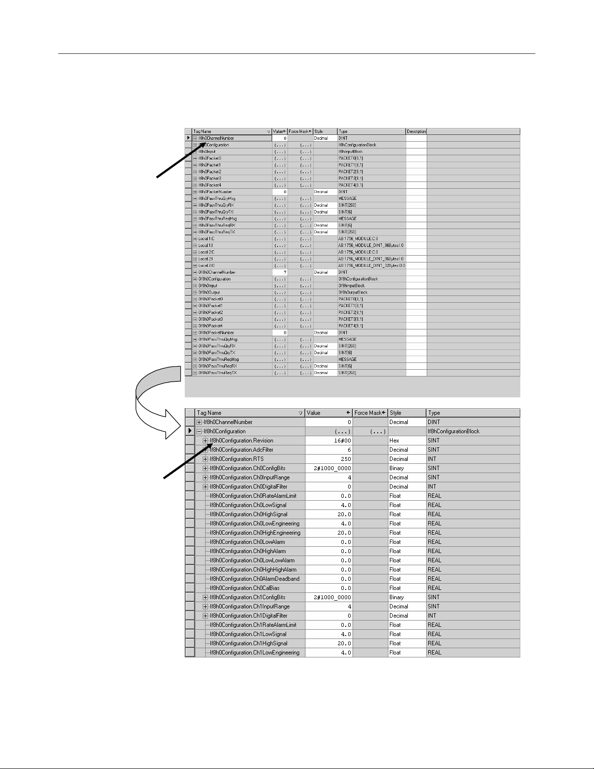
48 ControlLogix™ Analog HART Modules
You can view tags here.
Click on the tag name of the
data structure you want to see
Configuration in formation is
listed for each channel on the
module
Page 63
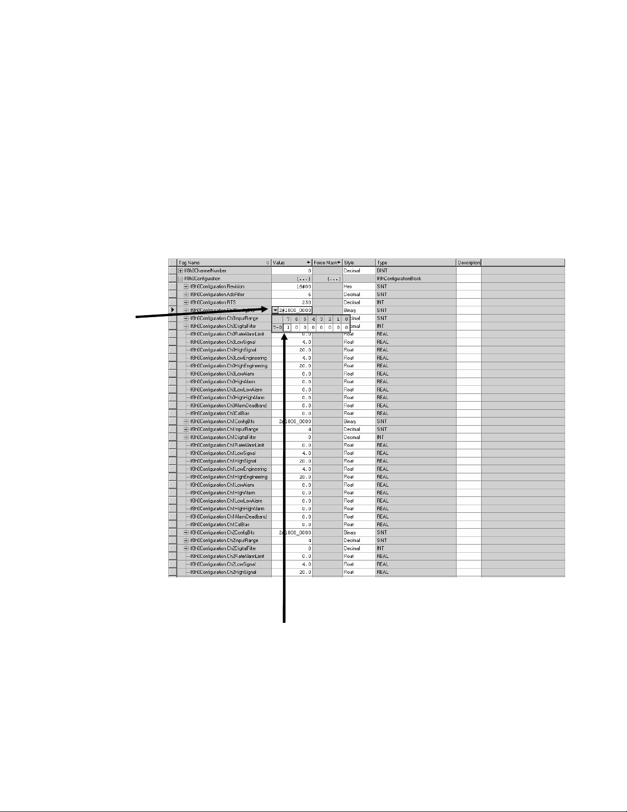
ChangingChanging
Changing
ChangingChanging
ConfigurationConfiguration
Configuration
ConfigurationConfiguration
InfInf
oror
mama
Inf
or
InfInf
oror
the the
the
the the
1.) Click on the far left
side of the Value
column an a pulldown
menu appears.
tion ation a
ma
tion a
mama
tion ation a
TT
aa
gsgs
T
a
gs
TT
aa
gsgs
Chapter 5: 1756sc-IF8H Channel Configuration, Data, and Status 49
tt
t
tt
There are two ways to change the configuration:
•
Use a pulldown menu
•
Highlight the value of a particular feature for a particular point and
type a new value
Pulldown menu
2.) Highlight the point that
needs to be changed and type a
valid new value
Highlight value
Page 64
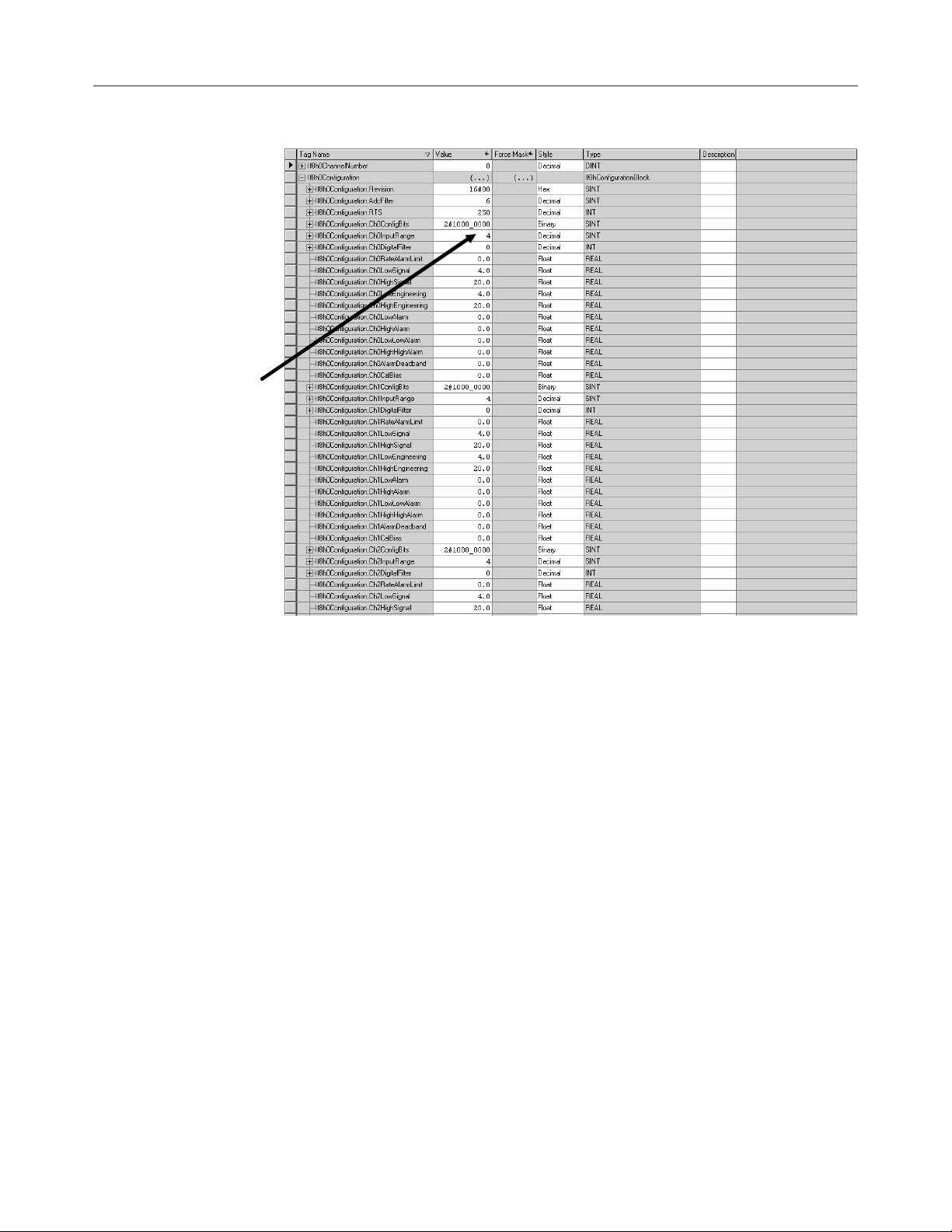
50 ControlLogix™ Analog HART Modules
1.) Highlight the value of
the feature you want to
change
2.) Type in the valid new
value.
Page 65

Chapter 6: 1756sc-OF8H Channel Configuration, Data, and Status 51
Configuration, Data,Configuration, Data,
Configuration, Data,
Configuration, Data,Configuration, Data,
Chapter 6
and Staand Sta
and Sta
and Staand Sta
for the 1756sc-OF8Hfor the 1756sc-OF8H
for the 1756sc-OF8H
for the 1756sc-OF8Hfor the 1756sc-OF8H
Read this chapter to:
• Send configuration data to the module
• Configuration tags
• Input tags
• Output tags
• Accessing the module tags
•
Changing configuration information at the tags
This chapter outlines the detailed settings for the 1756sc-OF8H. These
settings determine the modules input types, scan rates, and various
attributes. Detailed descriptions of these settings are available in the Tag
Definition section of this chapter.
tus tus
tus
tus tus
TT
T
TT
aa
a
aa
gsgs
gs
gsgs
SendSend
Send
SendSend
ConfigurationConfiguration
Configuration
ConfigurationConfiguration
Data to theData to the
Data to the
Data to theData to the
ModuleModule
Module
ModuleModule
Note: The following format is used to describe tags
Tag Name Data Type Style Description
After changing the configuration tags in this chapter you must then send
them to the module. To do this you may perform any of these operations:
1. Inhibit then un-inhibit the module via the module properties dialog,
Connection Tab
2. Reset the module via the modules properties dialog. Module Info tab.
3. Reset the module via ladder logic. See the “DoReset” rung in the
sample ladder located in Chapter 8.
4. Perform a “Set Attribute All” or Module Reconfigure message
instruction via ladder logic. Refer to Chapter 8 for information about the
“DoSetAttrAll” command.
Note: If an invalid configuration is sent to the module a connection error
will occur. See chapter 9 for a list of error codes.
Page 66

52 ControlLogix™ Analog HART Modules
ConfigurationConfiguration
Configuration
ConfigurationConfiguration
TT
aa
gs fgs f
T
a
gs f
TT
aa
gs fgs f
1756sc-OF8H1756sc-OF8H
1756sc-OF8H
1756sc-OF8H1756sc-OF8H
or theor the
or the
or theor the
The following tags allow for custom configuration of the module. These
tags can be found within the controller scope under the tag name
Of8h0Configuration.
Tag Nam e Data Type Style De scription
Of8h0Configuration Of8hConfigurationBlock NA Module configuration
Of8h0Configuration.ConfigRevision SINT DEC Controls multiple owner connections.
Of8h0Configuration.ProgToFaultEn SINT DEC The program to fault enable bit
Of8h0Configuration.Spare INT DEC Unused
Of8h0Configuration.ChXConfigBit s
Of8h0Configuration.ChXConfigBit s.0
Of8h0Configuration.ChXConfigBit s.1
1
X represents the module channel number (0 to 7).
1
1
1
Table 6.1a
0 = Always connect , overwrite w/new
configuration.
1 = Only c onnect if configuration
matches existing configuration.
determines how the outputs should
behave if a communicat ions fault
were to occur while the output
module is in the program mode.
0 = Outputs will remain in their
configured program state despite a
communications fault occurring.
1 = will cause t he outputs to
transition to their programmed fault
state if a communications fault
occurs while in t he program state.
Set to zero
INT BIN This is a s et of individual channel
configuration bits which enable
various functions for the ass ociated
channel.
BOOL DEC Enables ramping of the output value
to a us er defined fault value
(ChXFaultValue)
0 = Feature disabled
1 = During a fault condition the
associated channel will ramp to the
value stored in the ChXFaultValue tag
at a rate defined by the value stored
in the ChXMaxRampRate.
BOOL DEC Enables ramping of the output value
to a user defined idle value
(ChXIdleValue)
0 = Feature disabled
1 = When the PLC is in program
mode the assoc iated channel will
ramp to the value stored in the
ChXIdleValue tag at a rate defined by
the value stored in the
ChXMaxRampRate.
Page 67

Chapter 6: 1756sc-OF8H Channel Configuration, Data, and Status 53
Table 6.1b
Tag Name Data Type Style Description
1
Of8h0Configuration.ChXConfigBits.2
BOOL DEC Enables ramping of the output value
when the PLC is in RUN mode.
0 = Feature disabled
1 = When the PLC is in RUN mode
the associated channel will ramp to a
new output level at a rate defined by
the value stored in the
ChXMaxRampRat e t ag.
1
Of8h0Configuration.ChXConfigBits.3
BOOL DEC Selects the behavior of the output
channel when transitioning into
Program mode.
0 = Hold last state
1 = go to the value stored in the
ChXIdleValue tag.
1
Of8h0Configuration.ChXConfigBits.4
BOOL DEC Selects the behavior of the output
channel when a communication fault
occurs.
0 = Hold last state
1 = go to the value stored in the
ChXFaultValue tag.
1
Of8h0Configuration.ChXConfigBits.5
BOOL DEC Enables latching for the clamp limit
alarms.
0 = Feature disabled
1 = Clamp limit alarm will remain set
until an unlatch service is explicitly
sent to the channel or alarm.
1
Of8h0Configuration.ChXConfigBits.6
BOOL DEC Enables latching for all four process
alarms: low, low low, high, and high
high.
0 = Alarms unlatched
1 = process alarms will remain set
until an unlatch service is explicitly
sent to the channel or alarm.
1
Of8h0Configuration.ChXConfigBits.7
BOOL DEC Disable alarms
0 = Alarms enabled
1 = Disable all alarms
1
X represents the module channel number (0 to 7).
Page 68

54 ControlLogix™ Analog HART Modules
Tag Name Data Type Style Description
Of8h0Configuration.ChXConfigBits.8
Of8h0Configuration.ChXConfigBits.9
Of8h0Configuration.ChXConfigBits.10
Of8h0Configuration.ChXConfigBits.11
Of8h0Configuration.ChXConfigBits.12
Of8h0Configuration.ChXConfigBits.13
Of8h0Configuration.ChXConfigBits.14
Of8h0Configuration.ChXConfigBits.15
Of8h0Configuration.ChXOutputRange
Of8h0Configuration.ChXMaxRampRate
Of8h0Configuration.ChXFaultValue
1
X represents the module channel number (0 to 7).
1
Table 6.1c
1
BOOL DEC Hold for initialization
0 = Feature disabled
1 = The channel will hold, or not
change, until initialized with a value
within 0.1% of full scale of its current
value when one of the following
conditions occurs: Module initial
connection (power-up), module
transitions from program mode back
to run mode, module reestablishes
communicati on after a fault.
1
BOOL DEC Enables HART communication for the
channel.
0 = HART disabled
1 = HART Enabled
1
BOOL DEC Unused
Set to zero
1
BOOL DEC Unused
Set to zero
1
BOOL DEC Unused
Set to zero
1
BOOL DEC Unused
Set to zero
1
BOOL DEC Unused
Set to zero
1
BOOL DEC Unused
Set to zero
1
INT DEC Configures the channel’s output
range.
0 = +/-10 VDC
1 = 0 to 20mA
2 = 4 to 20mA
1
FLOAT REAL Configures the maximum rate at
which the output value may change.
Active only if bits 0, 1 or 2 are set in
the ChXConfigBits tag. Entered in
user sc aling units per second.
Defines the value, in engineering
units, t he output should take if a
communications fault occurs when bit
0 is set in the ChXConfigBits tag.
Page 69

Chapter 6: 1756sc-OF8H Channel Configuration, Data, and Status 55
Table 6.1d
Tag Name Data Type Style Description
Of8h0Configuration.ChXIdleValue
1
FLOAT REAL Defines the value, in engineering
units, the output should take when
the connection transitions to Program
mode. This function is only ac tive
when bit 1 is set in the ChXConfigBits
tag.
Of8h0Configuration.ChXLowSignal
1
FLOAT REAL One of four points used in scaling.
The low signal represents the
minimum output range.
Of8h0Configuration.ChXHighSignal
1
FLOAT REAL One of four points used in scaling.
The high signal represents the
maximum output range.
1
Of8h0Configuration.ChXLowEngineering
FLOAT REAL One of four points used in scaling.
The low engineering represents the
minimum scaled range.
1
Of8h0Configuration.ChXHighEngineering
FLOAT REAL One of four points used in scaling.
The high engineering represents the
maximum scaled range.
Of8h0Configuration.ChXLowClamp
1
FLOAT REAL Defines the minimum analog output
value the channel is allowed to
achieve.
Of8h0Configuration.ChXHighClamp
1
FLOAT REAL Defines the maximum analog output
value the channel is allowed to
achieve.
Of8h0Configuration.ChXCalBias
1
FLOAT REAL A us er configurable offset added
directly to the measured analog value
for the channel.
Of8h0Configuration.ChXSlot0Code
1
SINT DEC HART slot 0 transmitter variable
assignment code. Refer to chapter 7
for more information.
Of8h0Configuration.ChXSlot1Code
1
SINT DEC HART slot 1 transmitter variable
assignment code. Refer to chapter 7
for more information.
Of8h0Configuration.ChXSlot2Code
1
SINT DEC HART slot 2 transmitter variable
assignment code. Refer to chapter 7
for more information.
Of8h0Configuration.ChXSlot3Code
1
SINT DEC HART slot 3 transmitter variable
assignment code. Refer to chapter 7
for more information.
1
X represents the module channel number (0 to 7).
Page 70

56 ControlLogix™ Analog HART Modules
Table 6.1e
Tag Name Data Type Style Description
Of8h0Configuration.HandleTimeout INT DEC There is a handle timeout associated
with the final reply mess age. After
the module obtaines the requested
information from the HART device, it
will start the HandleTimeout timer
(duration defined by the
HandleTimeout tag). The replay
message will be kept in memory
during the HandleTimeout period.
After the timeout occurs or after the
message is retrieved by the passthrough respons e query command,
the storage buffer will be discarded,
and another pass through message
will be serviced without being
rejected. HandleTimeout is in the
range of 1 to 255 sec onds.
Of8h0Configuration.ModuleConfigBits INT BIN Module function settings
Of8h0Configuration.ModuleConfigBits.0 BOOL DEC Reserved set to zero
Of8h0Configuration.ModuleConfigBits.1 BOOL DEC Reserved set to zero
Of8h0Configuration.ModuleConfigBits.2 BOOL DEC Reserved set to zero
Of8h0Configuration.ModuleConfigBits.3 BOOL DEC Reserved set to zero
Of8h0Configuration.ModuleConfigBits.4 BOOL DEC Reserved set to zero
Of8h0Configuration.ModuleConfigBits.5 BOOL DEC Reserved set to zero
Of8h0Configuration.ModuleConfigBits.6 BOOL DEC Reserved set to zero
Of8h0Configuration.ModuleConfigBits.7 BOOL DEC Reserved set to zero
Of8h0Configuration.ModuleConfigBits.8 BOOL DEC Reserved set to zero
Of8h0Configuration.ModuleConfigBits.9 BOOL DEC Reserved set to zero
Of8h0Configuration.ModuleConfigBits.10 BOOL DEC Reserved set to zero
Of8h0Configuration.ModuleConfigBits.11 BOOL DEC Reserved set to zero
Of8h0Configuration.ModuleConfigBits.12 BOOL DEC Reserved set to zero
Of8h0Configuration.ModuleConfigBits.13 BOOL DEC Reserved set to zero
Page 71

Chapter 6: 1756sc-OF8H Channel Configuration, Data, and Status 57
Table 6.1f
Tag Name Data Type Style Description
Of8h0Configuration.ModuleConfigBits.14
Of8h0Configuration.ModuleConfigBits.15
2
The configuration of bits 14 and 15 directly effec t the update time of the HART data acquisition for the module, f or
example if bit 15 is set, the HART update time for each channel w ill be doubled.
2
BOOL DEC Bits 14 and 15 determine how often
the pass-through command is
serviced by the module.
15,14 = 00 = pass-through serviced
once per two channels scanned
15,14 = 01 = pass-through serviced
once per module scan
15,14 = 1X = pass-through servic ed
2
BOOL DEC Bits 14 and 15 determine how often
once per channel scan
the pass-through command is
serviced by the module.
15,14 = 00 = pass-through serviced
once per two channels scanned
15,14 = 01 = pass-through serviced
once per module scan
15,14 = 1X = pass-through servic ed
once per channel scan
Input Input
Input
Input Input
TT
T
TT
aa
a
aa
gsgs
gs
gsgs
The following fault and status reporting and module data sections allow
monitoring of faults, status, and input data from the module. These tags
can be found within the Of8h0Input controller tag.
Page 72

58 ControlLogix™ Analog HART Modules
Tag Name Data Type Style Description
Of8h0Input Of8h0InputBlock NA Module input data
Of8h0Input.ModuleStatus DINT BIN General module status
Of8h0Input.ModuleStatus.0 BOOL DEC Channel 0 general fault status
Of8h0Input.ModuleStatus.1 BOOL DEC Channel 1 general fault status
Of8h0Input.ModuleStatus.2 BOOL DEC Channel 2 general fault status
Of8h0Input.ModuleStatus.3 BOOL DEC Channel 3 general fault status
Of8h0Input.ModuleStatus.4 BOOL DEC Channel 4 general fault status
Of8h0Input.ModuleStatus.5 BOOL DEC Channel 5 general fault status
Of8h0Input.ModuleStatus.6 BOOL DEC Channel 6 general fault status
Of8h0Input.ModuleStatus.7 BOOL DEC Channel 7 general fault status
Of8h0Input.ModuleStatus.8 BOOL DEC Loop output fault
Of8h0Input.ModuleStatus.9 BOOL DEC Unused
Of8h0Input.ModuleStatus.10 BOOL DEC Unused
Of8h0Input.ModuleStatus.11 BOOL DEC Unused
Of8h0Input.ModuleStatus.12 BOOL DEC Unused
Of8h0Input.ModuleStatus.13 BOOL DEC Unused
Of8h0Input.ModuleStatus.14 BOOL DEC Unused
Of8h0Input.ModuleStatus.15 BOOL DEC Unused
Table 6.2a
0 = No fault
1 = Fault
0 = No fault
1 = Fault
0 = No fault
1 = Fault
0 = No fault
1 = Fault
0 = No fault
1 = Fault
0 = No fault
1 = Fault
0 = No fault
1 = Fault
0 = No fault
1 = Fault
0 = No Fault
1 = Fault
Page 73

Chapter 6: 1756sc-OF8H Channel Configuration, Data, and Status 59
Table 6.2b
Tag Name Data Type Style Description
Of8h0Input.ModuleStatus.16 BOOL DEC Channel 0 HART out-of-service
0 = In service
1 = Out-of-service
Of8h0Input.ModuleStatus.17 BOOL DEC Channel 1 HART out-of-service
0 = In service
1 = Out-of-service
Of8h0Input.ModuleStatus.18 BOOL DEC Channel 2 HART out-of-service
0 = In service
1 = Out-of-service
Of8h0Input.ModuleStatus.19 BOOL DEC Channel 3 HART out-of-service
0 = In service
1 = Out-of-service
Of8h0Input.ModuleStatus.20 BOOL DEC Channel 4 HART out-of-service
0 = In service
1 = Out-of-service
Of8h0Input.ModuleStatus.21 BOOL DEC Channel 5 HART out-of-service
0 = In service
1 = Out-of-service
Of8h0Input.ModuleStatus.22 BOOL DEC Channel 6 HART out-of-service
0 = In service
1 = Out-of-service
Of8h0Input.ModuleStatus.23 BOOL DEC Channel 7 HART out-of-service
0 = In service
1 = Out-of-service
Of8h0Input.ModuleStatus.24 BOOL DEC Unused
Of8h0Input.ModuleStatus.25 BOOL DEC Calibration fault
0 = No fault
1 = Fault
Of8h0Input.ModuleStatus.26 BOOL DEC Calibration in progress
0 = Calibration NOT active
1 = Calibrating
Of8h0Input.ModuleStatus.27 BOOL DEC Unused
Of8h0Input.ModuleStatus.28 BOOL DEC Unused
Of8h0Input.ModuleStatus.29 BOOL DEC Unused
Of8h0Input.ModuleStatus.30 BOOL DEC Unused
Of8h0Input.ModuleStatus.31 BOOL DEC Analog group fault
0 = No fault
1 = Fault
Page 74

60 ControlLogix™ Analog HART Modules
Tag Name Data Type Style Description
Of8h0Input.ChanStatus SINT[8] BIN An array of 8 SINT which display
1
Of8h0Input.ChanStatus[X]
Of8h0Input.ChanStatus[X].0
Of8h0Input.ChanStatus[X].1
Of8h0Input.ChanStatus[X].2
Of8h0Input.ChanStatus[X].3
Of8h0Input.ChanStatus[X].4
Of8h0Input.ChanStatus[X].5
Of8h0Input.ChanStatus[X].6
Of8h0Input.ChanStatus[X].7
SINT BIN General channel status byte
1
BOOL DEC User value exceeded high clamp
1
BOOL DEC User value exceeded low clamp limit.
1
BOOL DEC Specified ramp rate exceeded.
1
BOOL DEC Channel holding last output value.
1
BOOL DEC Channel calibration fault
1,2
BOOL DEC Invalid or NaN channel value
1
BOOL DEC Unused
1
BOOL DEC Open wire fault (Current Only)
Of8h0Input.ChanData REAL[8] FLOAT An array of 8 floating point registers
Of8h0Input.ChanData[X]
1
X represents the module channel number (0 to 7).
2
An invalid data value is being used f or the associated channel's output tag (i.e. Of8h0.Output.ChXData)
1
REAL FLOAT Channel analog data in engineering
Table 6.2c
general status for each channel.
limit.
0 = No alarm
1 = Alarm
0 = No alarm
1 = Alarm
0 = No alarm
1 = Alarm
0 = Normal
1 = Holding
0 = No fault
1 = Fault
0 = No alarm
1 = Alarm
0 = No fault
1 = Fault
which dis play the analog data for
each channel in engineering units.
units
Page 75
Chapter 6: 1756sc-OF8H Channel Configuration, Data, and Status 61
Table 6.2d
Tag Name Data Type Style Description
Of8h0Input.CST DINT[2] DEC This is the timestamp taken at the
time the input data was sampled,
which is in terms of coordinated
system time. This is a 64 bit
quantity in microseconds coordinated
across the rack. This must be
addressed in 32 bit segments as an
array.
Of8h0Input.TimeStamp INT DEC This is the times tamp taken at time
the input data was sampled, which is
shown in milliseconds relative solely
to the individual module.
Of8h0Input.HartData SINT[40] DEC An array of 40 bytes which contains
HART packet data for the entir more
details.
Output Output
Output
Output Output
Tag Name Data Type Style Description
Of8h0Output Of8hOutputBlock NA Module output data
Of8h0Output.Ch0Data FLOAT REAL Controls the analog output signal for
Of8h0Output.Ch1Data FLOAT REAL Controls the analog output signal for
Of8h0Output.Ch2Data FLOAT REAL Controls the analog output signal for
Of8h0Output.Ch3Data FLOAT REAL Controls the analog output signal for
Of8h0Output.Ch4Data FLOAT REAL Controls the analog output signal for
Of8h0Output.Ch5Data FLOAT REAL Controls the analog output signal for
Of8h0Output.Ch6Data FLOAT REAL Controls the analog output signal for
Of8h0Output.Ch7Data FLOAT REAL Controls the analog output signal for
TT
T
TT
aa
a
aa
gsgs
gs
gsgs
The output tags are used to control the analog signals for each channel.
See the table below for more details.
Table 6.3
channel 0
channel 1
channel 2
channel 3
channel 4
channel 5
channel 6
channel 7
Page 76

62 ControlLogix™ Analog HART Modules
Accessing TheAccessing The
Accessing The
Accessing TheAccessing The
Module Module
Module
Module Module
TT
T
TT
aa
a
aa
gsgs
gs
gsgs
When you access tags to change configuration or monitor the I/O data
exchange, you have two options.:
•
Monitor tags - option allows you to view tags and change their values.
•
Edit tags - option allows you to add or delete tags, but not to change
their values.
1.) Select Controller Tags
2.) Right-click to display the
menu
3.) Select Monitor Tags
Page 77
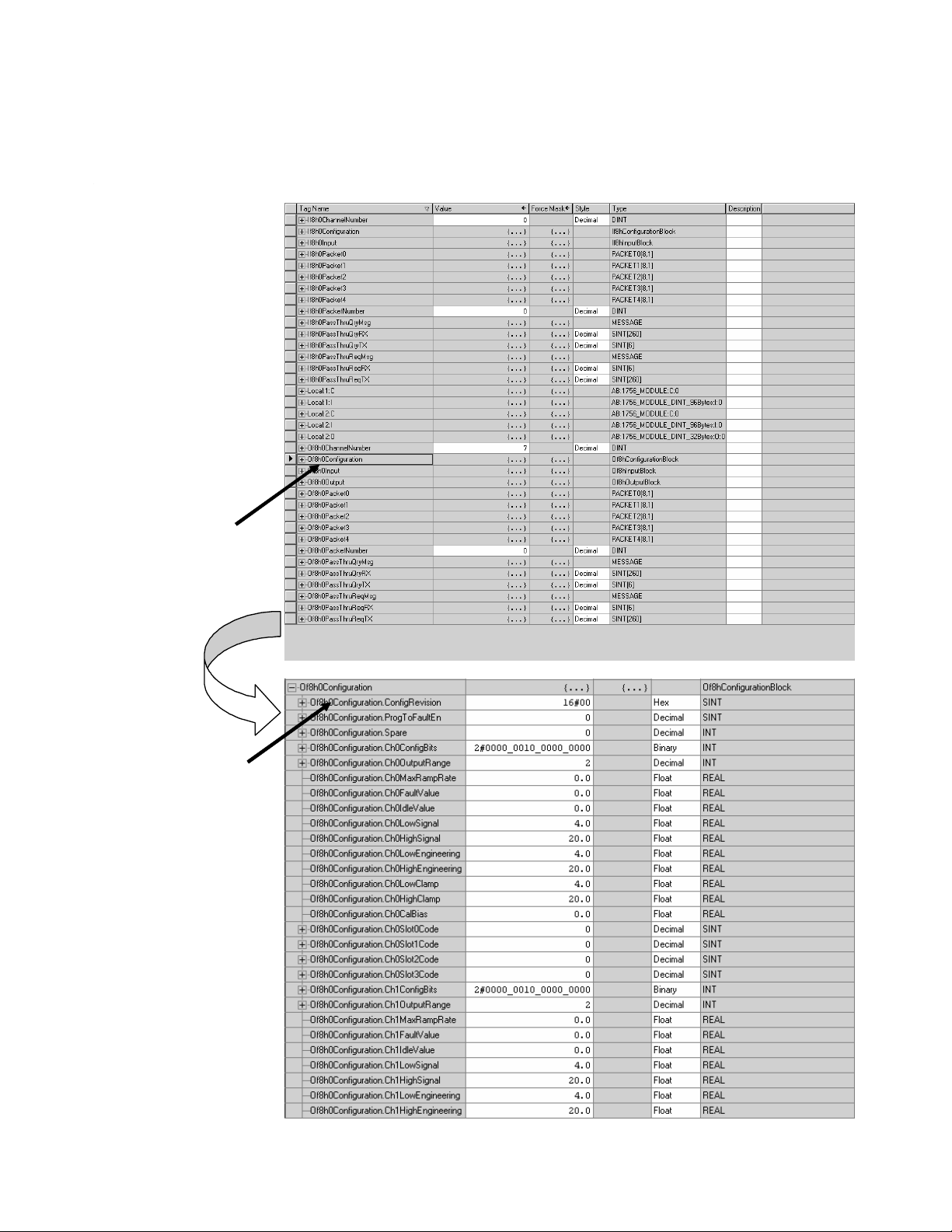
Click on the tag name of the
data structure you want to see
Chapter 6: 1756sc-OF8H Channel Configuration, Data, and Status 63
You can view tags here.
Configuration information is
listed for each chann el on the
module
Page 78
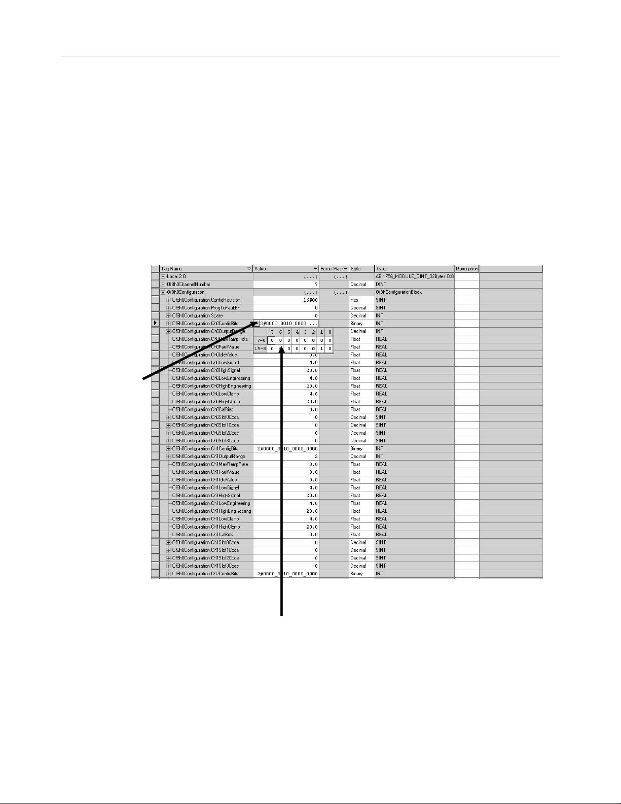
64 ControlLogix™ Analog HART Modules
ChangingChanging
Changing
ChangingChanging
ConfigurationConfiguration
Configuration
ConfigurationConfiguration
InfInf
oror
mama
Inf
or
InfInf
oror
the the
the
the the
tion ation a
ma
tion a
mama
tion ation a
TT
aa
gsgs
T
a
gs
TT
aa
gsgs
tt
t
tt
There are two ways to change the configuration:
•
Use a pulldown menu
•
Highlight the value of a particular feature for a particular point and
type a new value
Pulldown menu
1.) Click on the far left
side of the Value
column and a pulldown
menu appears.
2.) Highlight the point that
needs to be changed and type a
valid new value
Page 79
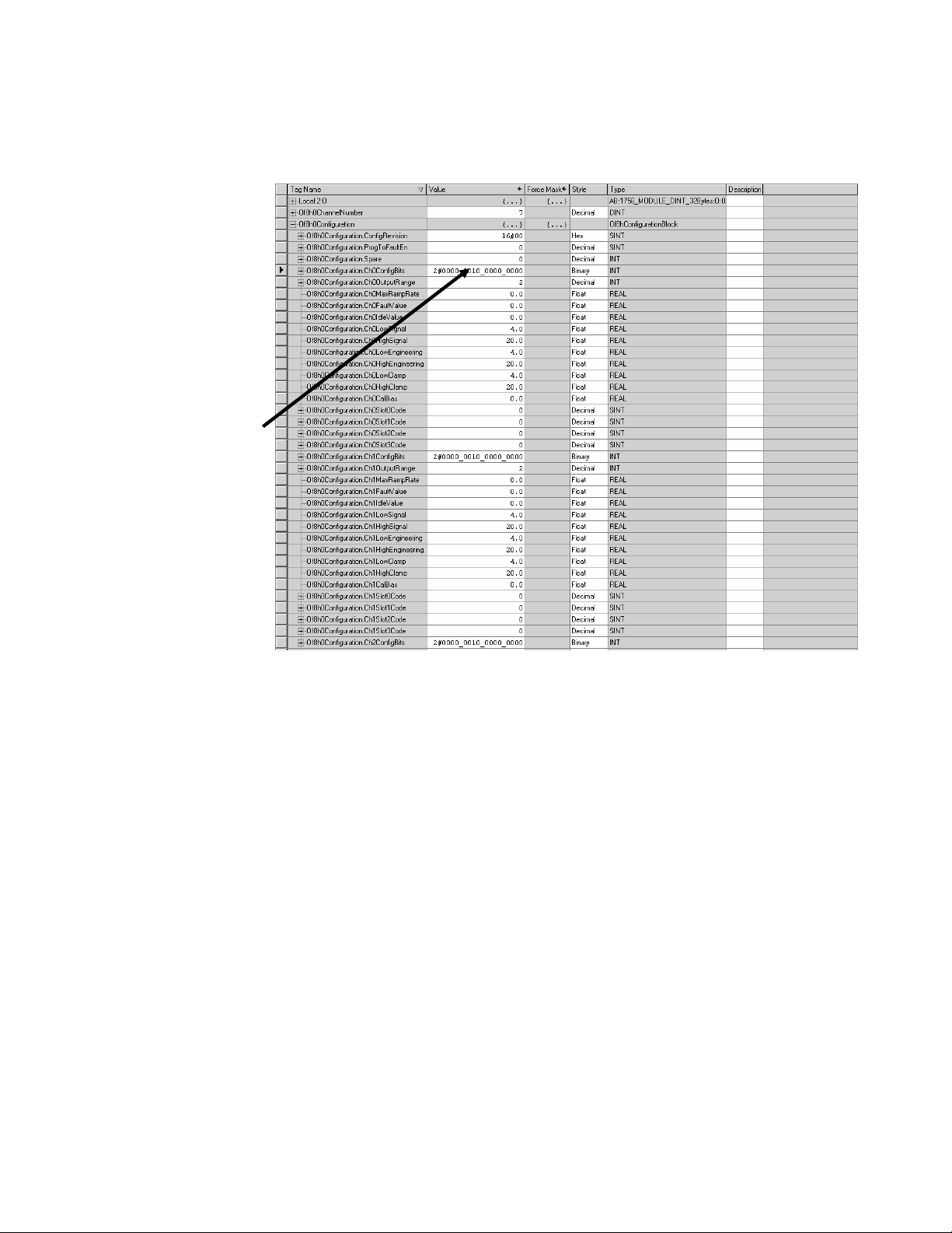
1.) Highlight the value of
the feature you want to
change
2.) Type in the valid new
value.
Chapter 6: 1756sc-OF8H Channel Configuration, Data, and Status 65
Highlight value
Page 80

66 ControlLogix™ Analog HART Modules
Page 81
Configuring theConfiguring the
Configuring the
Configuring theConfiguring the
Modules forModules for
Modules for
Modules forModules for
HARTHART
HART
HARTHART
Chapter 7: HART Channel Configuration, Data, and Status 67
Enabling and Using HART on theEnabling and Using HART on the
Enabling and Using HART on the
Enabling and Using HART on theEnabling and Using HART on the
1756sc-IF8H and OF8H1756sc-IF8H and OF8H
1756sc-IF8H and OF8H
1756sc-IF8H and OF8H1756sc-IF8H and OF8H
This chapter outlines the detailed settings and configuration related to
HART communication for the 1756sc-IF8H and 1756sc-OF8H modules.
These settings determine how the modules acquire HART data.
The chapter is broken down into the following sections:
• Configuring the modules for HART
• How the modules send and receive HART data
• HART protocol overview
ConfConf
Conf
ConfConf
Acquisition/Communication)Acquisition/Communication)
Acquisition/Communication)
Acquisition/Communication)Acquisition/Communication)
iguring the IF8H Module figuring the IF8H Module f
iguring the IF8H Module f
iguring the IF8H Module figuring the IF8H Module f
Chapter 7
or (Haror (Har
or (Har
or (Haror (Har
tt
t
tt
•
In order for HART to be active on any given channel, the channel
configuration must contain the following basic settings:
•
Bit 7 (Enable HART), in the If8h0Configuration.ChXConfigBits tag,
needs to be set. See chapter 5 for more details.
•
An appropriate ADC filter range must be selected.
Attention: The 1000Hz ADC filter setting is notAttention: The 1000Hz ADC filter setting is not
Attention: The 1000Hz ADC filter setting is not
Attention: The 1000Hz ADC filter setting is notAttention: The 1000Hz ADC filter setting is not
!
allowed when HART is enabled.allowed when HART is enabled.
allowed when HART is enabled.
allowed when HART is enabled.allowed when HART is enabled.
•
The If8h0Configuration.ChXInputRange tag must be set to 4 for a 4 to
mA current range.
Attention: Attention:
Attention:
Attention: Attention:
!
improved by disabling HART communication on improved by disabling HART communication on
improved by disabling HART communication on
improved by disabling HART communication on improved by disabling HART communication on
channels or channels that include non-HART devices.channels or channels that include non-HART devices.
channels or channels that include non-HART devices.
channels or channels that include non-HART devices.channels or channels that include non-HART devices.
HART throughput time can beHART throughput time can be
HART throughput time can be
HART throughput time can beHART throughput time can be
unusedunused
unused
unusedunused
Page 82

68 ControlLogix™ Analog HART Modules
Figure 7.1 (Channel 0 Configuration Example)
ConfConf
Conf
ConfConf
Acquisition/Communication)Acquisition/Communication)
Acquisition/Communication)
Acquisition/Communication)Acquisition/Communication)
iguring the OF8H Module figuring the OF8H Module f
iguring the OF8H Module f
iguring the OF8H Module figuring the OF8H Module f
or (Haror (Har
or (Har
or (Haror (Har
tt
t
tt
In order for HART to be active on any given channel, the channel
configuration must contain the following basic settings:
•
Bit 9 (Enable HART), in the Of8h0Configuration.ChXConfigBits tag,
needs to be set. See chapter 6 for more details.
•
The Of8h0Configuration.ChXOutputRange tag must be set to 2 for a 4
to 20 mA current range.
Attention: Attention:
Attention:
Attention: Attention:
!
improved by disabling HART communication on improved by disabling HART communication on
improved by disabling HART communication on
improved by disabling HART communication on improved by disabling HART communication on
channels or channels that include non-HART devices.channels or channels that include non-HART devices.
channels or channels that include non-HART devices.
channels or channels that include non-HART devices.channels or channels that include non-HART devices.
HART throughput time can beHART throughput time can be
HART throughput time can be
HART throughput time can beHART throughput time can be
unusedunused
unused
unusedunused
Page 83

Chapter 7: HART Channel Configuration, Data, and Status 69
Figure 7.2 (Channel 0 Configuration Example)
How theHow the
How the
How theHow the
Modules SendModules Send
Modules Send
Modules SendModules Send
and Receiveand Receive
and Receive
and Receiveand Receive
HART DataHART Data
HART Data
HART DataHART Data
How the Module Connects to a Field DeviceHow the Module Connects to a Field Device
How the Module Connects to a Field Device
How the Module Connects to a Field DeviceHow the Module Connects to a Field Device
Both the HART input and Output module behave as a HART master in
which case the field device is considered the slave. In other words, the
master must initiate the communication with the field device and the
device simply replies with an appropriate response. Any given channel
may have a master, a secondary master (hand held configuration tool), and
a slave connected simultaneously. Please see Figure 3.
Page 84

70 ControlLogix™ Analog HART Modules
Figure 7.3 (Primary, Secondary and Slave connection)
Attention:Attention:
Attention:
Attention:Attention:
!
the IF8H or the OF8H.the IF8H or the OF8H.
the IF8H or the OF8H.
the IF8H or the OF8H.the IF8H or the OF8H.
Har Har
Har
Har Har
t mt m
t m
t mt m
ulti-drulti-dr
ulti-dr
ulti-drulti-dr
op is not supporop is not suppor
op is not suppor
op is not supporop is not suppor
ted bted b
ted b
ted bted b
yy
y
yy
HART modules communicate using two different messaging schemes
connected and unconnected. Connected messages are messages that are
periodically updated and maintained by the ControlLogix processor. The
frequencies of the updates are adjustable and are defined by the user.
Connected messages include data contained in the module’s input image,
and in the case of the OF8H module, the output image. Unconnected
messages are messages that are transmitted over the control network and
are performed asynchronously from the normal processor scan.
Unconnected messages include data contained in the module’s
configuration image (i.e. Local:e:C), and CIP messages such as the
module specific commands. Module specific commands include the
HART pass-through commands, HART suspension and resume, and the
get HART device information command.
Page 85

Chapter 7: HART Channel Configuration, Data, and Status 71
Figure 7.4 (Connected and Unconnected messaging)
• Analog data
Connected
Unconnected
• Module status
• HART Dynamic
Variables
• HART device codes
• Module Configuration
• Any CIP message
• HART Pass-Through
The module uses the two communication schemes to gather HART data.
Gathering HART data is accomplished using two processes auto
acquisition, and or using the module specific commands.
Auto AcquisitionAuto Acquisition
Auto Acquisition
Auto AcquisitionAuto Acquisition
When a channel is configured for HART, the module will automatically
search and establish a connection to any HART field device wired to the
channel. Once the module establishes a connection it will begin to acquire
HART data, including device specific codes (i.e. Manufacturer ID, serial
number, etc.), the four dynamic variables, extended device status, slot
variables (OF8H only), and any stored ASCII message descriptor that
may be present. The HART data retrieved automatically by the module is
then displayed in the input image and is accessible by ladder logic. The
HART data will update, on average, every 6.5 seconds if all eight channels
are enabled for HART. The module initiates the connection by sending a
string of HART commands to the field device. Please see figure below.
Page 86

72 ControlLogix™ Analog HART Modules
Figure 7.5 (Auto Acquisition Flow)
Start
Initialized
for
HART?
YES
Channel
Switch
Connect to field
device
Read device
codes
NO
Read ASCII
messages
Read PVU and
PVL
Read 4 dynamic
variables
Read extended
status
Read slot variables
(OF8H Only)
The data that is collected from the process described in figure 7.5 is
buffered to the modules RAM memory. Since the amount of data
returned from the auto-acquisition process is extensive, utilizing the module
input tags efficiently would not be practical unless the data is multiplexed.
Therefore, the data is multiplexed into five separate packets and for each
individual channel. The packets are defined in tables 7.1 to 7.5.
Page 87

Chapter 7: HART Channel Configuration, Data, and Status 73
Table 7.1(Packet 0)
Tag Name Data Type
(If8h0 or Of8h0)Packet0
1
Packet0[8,1] NA Two dimmensional array containing
Style
Description
packet 0 data for all 8 channels.
(If8h0 or Of8h0)Packet0[X,0]
1,2
(If8h0 or Of8h0)Packet0[X,0].HartChannelID INT BIN
Packet0 NA Packet 0 data for channel X
Bits 0 to 3: Channel number (0 – 7).
Bit 4: Searching/Initializing HART device
Bit 5: HART communication failure or
device not found
Bit 6: Pass-through message pending
(ready)
Bit 7: Unu s ed (0)
Bits 8 to 10: Packet ID
Bit 11 through 15: Unused
(If8h0 or Of8h0)Packet0[X,0].ManufacturerID SINT DEC
(If8h0 or Of8h0)Packet0[X,0].DeviceType SINT DEC
(If8h0 or Of8h0)Packet0[X,0].NumPreambles SINT DEC
HART device Manufacturer ID
HART device type code
Minimum number of preambles the device
req uires.
(If8h0 or Of8h0)Packet0[X,0].UniversalCmdCode SINT DEC
(If8h0 or Of8h0)Packet0[X,0].XmitterRev SINT DEC
(If8h0 or Of8h0)Packet0[X,0].SwRev SINT DEC
(If8h0 or Of8h0)Packet0[X,0].HwRev SINT DEC
(If8h0 or Of8h0)Packet0[X,0].HartFlags SINT BIN
(If8h0 or Of8h0)Packet0[X,0].RangeUnits SINT DEC
(If8h0 or Of8h0)Packet0[X,0].DeviceSerialNumber SINT[3] HEX
(If8h0 or Of8h0)Packet0[X,0].DeviceTag SINT[8] ASCII
HART Univ ersal command code
HART Transmitter specific revision
HART device software revision number
HART device hardware revision number
HART flags
Units code for range parameter
HART device ID number
8 character device tag
(If8h0 or Of8h0)Packet0[X,0].DeviceDescriptor SINT[16] ASCII
1
The name in parentheses repres ents the module tag name (i.e. If 8h0 or Of8h0) depending on w hich module is being used.
2
X represents the module channel number (0 to 7)
Page 88

74 ControlLogix™ Analog HART Modules
Table 7.2(Packet 1)
Tag Name Data Type
(If8h0 or Of8h0)Packet1
1
Packet1[8,1] NA Two dimensional array containing
Style
Des cri ption
packet 1 data for all 8 channels.
(If8h0 or Of8h0)Packet1[X,0]
1,2
(If8h0 or Of8h0)Packet1[X,0].HartChannelID INT BIN
Packet1 NA Pac ket 1 data for channel X
Bits 0 to 3: Chann el number (0 – 7).
Bit 4: Searching/Initializing HART device
Bit 5: HART communication failure or
device not found
Bit 6: Pass-through message pending
(ready)
Bit 7: Unused (0)
Bits 8 to 10: Packet ID
Bit 11 through 15: Unused
(If8h0 or Of8h0)Packet1[X,0].HartCommStatus SINT BIN
(If8h0 or Of8h0)Packet1[X,0].HartDevStatus SINT BIN
(If8h0 or Of8h0)Packet1[X,0].HartPV REAL FLOAT
(If8h0 or Of8h0)Packet1[X,0].HartSV REAL FLOAT
(If8h0 or Of8h0)Packet1[X,0].HartTV REAL FLOAT
(If8h0 or Of8h0)Packet1[X,0].HartFV REAL FLOAT
(If8h0 or Of8h0)Packet1[X,0].HartPVUnits SINT DEC
(If8h0 or Of8h0)Packet1[X,0].HartSVUnits SINT DEC
(If8h0 or Of8h0)Packet1[X,0].HartTVUnits SINT DEC
(If8h0 or Of8h0)Packet1[X,0].HartFVUnits SINT DEC
(If8h0 or Of8h0)Packet1[X,0].PV_Assignment SINT DEC
(If8h0 or Of8h0)Packet1[X,0].SV_Assignment SINT DEC
(If8h0 or Of8h0)Packet1[X,0].TV_Assignment SINT DEC
(If8h0 or Of8h0)Packet1[X,0].FV_As signment SINT DEC
(If8h0 or Of8h0)Packet1[X,0].RangeLow REAL FLOAT
HART communication status byt e. Refer to
appendix D for more details.
HART device status byt e. Refer to appendix D
for more details.
HART P rimary Variable
HART Secondary Variable
HART Tertiary Variable
HART Fo urth Variable
HART P rimary Variable unit s code
HART Secondary Variable units code
HART T ertiary Variable unit s code
HART Fo urt h Variable units co de
HART P rimary Variable co de
HART Secondary Variable code
HART Tertiary Variable code
HART Fo urth Variable code
Low transmitter range for analog signal in
engineering units
(If8h0 or Of8h0)Packet1[X,0].RangeHi REAL FLOAT
High transmitter range for analog signal in
engineering units
(If8h0 or Of8h0)Packet1[X,0].Pad SINT[4] DEC
1
The name in parentheses represents the module tag name (i.e. If8h0 or Of8h0) depending on w hich module is being used.
2
X represents the module channel number (0 to 7)
Packet pad (32 bit alignment)
Page 89

Chapter 7: HART Channel Configuration, Data, and Status 75
Table 7.3 (Packet 2)
Tag Name Data Type
(If8h0 or Of8h0)Packet2
1
Packet2[8,1] NA Two dimensional array containing
Style
Description
packet 2 data for all 8 channels.
(If8h0 or Of8h0)Packet2[X,0]
1,2
(If8h0 or Of8h0)Packet2[X,0].HartChannelID INT BIN
Packet2 NA Packet 2 data for channel X
Bits 0 to 3: Chann el number (0 – 7).
Bit 4: Searching/Initializing HART device
Bit 5: HART communication failure or
device not found
Bit 6: Pass-through message pending
(ready)
Bit 7: Unu s ed (0)
Bits 8 to 10: Packet ID
Bit 11 through 15: Unused
(If8h0 or Of8h0)Packet2[X,0].Slot0Data REAL Float
(If8h0 or Of8h0)Packet2[X,0].Slot1Data REAL Float
(If8h0 or Of8h0)Packet2[X,0].Slot2Data REAL Float
(If8h0 or Of8h0)Packet2[X,0].Slot3Data REAL Float
(If8h0 or Of8h0)Packet2[X,0].Slot0Units SINT DEC
(If8h0 or Of8h0)Packet2[X,0].Slot1Units SINT DEC
(If8h0 or Of8h0)Packet2[X,0].Slot2Units SINT DEC
(If8h0 or Of8h0)Packet2[X,0].Slot3Units SINT DEC
(If8h0 or Of8h0)Packet2[X,0].Slot0Assignment SINT DEC
(If8h0 or Of8h0)Packet2[X,0].Slot1Assignment SINT DEC
(If8h0 or Of8h0)Packet2[X,0].Slot2Assignment SINT DEC
(If8h0 or Of8h0)Packet2[X,0].Slot3Assignment SINT DEC
(If8h0 or Of8h0)Packet2[X,0].Pad SINT[12] DEC
1
The name in parentheses represents the module tag name (i.e. If8h0 or Of8h0) depending on w hich module is being used.
2
X represents the module channel number (0 to 7)
Variable for s lot 0
Variable for s lot 1
Variable for s lot 2
Variable for s lot 3
Slot 0 units code
Slot 1 units code
Slot 2 units code
Slot 3 units code
Slot 0 variable code
Slot 1 variable code
Slot 2 variable code
Slot 3 variable code
Packet pad
Attention: Slot variables are not acquiredAttention: Slot variables are not acquired
Attention: Slot variables are not acquired
Attention: Slot variables are not acquiredAttention: Slot variables are not acquired
!
automatically by the input module. Therefore, packet 2automatically by the input module. Therefore, packet 2
automatically by the input module. Therefore, packet 2
automatically by the input module. Therefore, packet 2automatically by the input module. Therefore, packet 2
is skipped by the auto-acquisition process.is skipped by the auto-acquisition process.
is skipped by the auto-acquisition process.
is skipped by the auto-acquisition process.is skipped by the auto-acquisition process.
Page 90

76 ControlLogix™ Analog HART Modules
Table 7.4 (Packet 3)
Tag Name Data Type
(If8h0 or Of8h0)Packet3
1
Packet3[8,1] NA Two dimensional array containing
Style
Des cription
packet 3 data for all 8 channels.
(If8h0 or Of8h0)Packet3[X,0]
1,2
(If8h0 or Of8h0)Packet3[X,0].HartChannelID INT BIN
Packet3 NA Packet 3 data for channel X
Bits 0 to 3: Channel number (0 – 7).
Bit 4: Searching/Initializing HART device
Bit 5: HART communication failure or
device not found
Bit 6: Pass-through message pending
(ready)
Bit 7: Unu s ed (0)
Bits 8 to 10: Packet ID
Bit 11 through 15: Unused
Message SINT[32] ASCII
Pad SINT[4] DEC
1
The name in parentheses repres ents the module tag name (i.e. If8h0 or Of8h0) depending on w hich module is being used.
2
X represents the module channel number (0 to 7)
32 character message
Pad 32 bit alignment.
Table 7.5 (Packet 4)
Tag Name Data Type
(If8h0 or Of8h0)Packet4
1
Packet4[8,1] NA Two dimensional array containing
Style
Description
packet 4 data for all 8 channels.
(If8h0 or Of8h0)Packet4[X,0]
1,2
(If8h0 or Of8h0)Packet4[X,0].HartChannelID INT BIN
Packet4[8,1] NA Packet 4 data for channel X
Bits 0 to 3: Chann el number (0 – 7).
Bit 4: Searching/Initializing HART device
Bit 5: HART communication failure or
device not found
Bit 6: Pass-through message pending
(ready)
Bit 7: Unu s ed (0)
Bits 8 to 10: Packet ID
Bit 11 through 15: Unused
Date SINT[3] DEC
FinalAss emblyNumber SINT[3] DEC
Stored date in the field device
The final assembly number is used for
identifying the materials and electronics
that comprise the field device.
ExtendedSt atus SINT[24] DEC
The extended status returned by HART
co mma nd 48
Pad SINT[3] DEC
1
The name in parentheses repres ents the module tag name (i.e. If8h0 or Of8h0) depending on w hich module is being used.
2
X represents the module channel number (0 to 7)
Pad 32 bit alignment
Note: Not all of the data that is returned by the process outlined in figure
7.5 gets passed to the packets. In order to access the data that is not
passed to the packets, you must execute the appropriate HART message
using the pass-through command, which will be discussed later in this
chapter.
Page 91
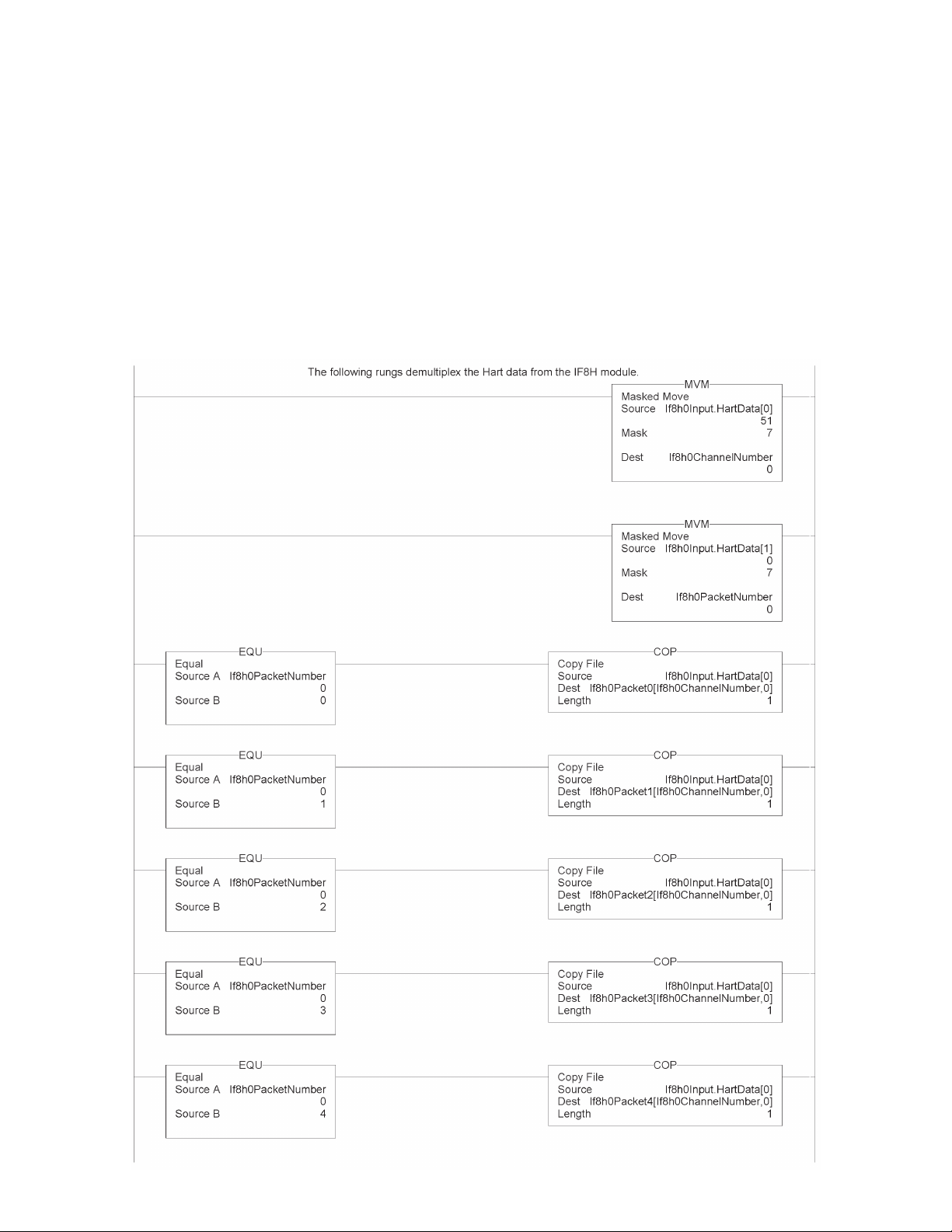
Chapter 7: HART Channel Configuration, Data, and Status 77
The HART data acquired by the auto acquisition process is copied to the
packet tags by using ladder. The ladder simply copies the data stored in
the (If8h0 or Of8h0)Input.HartDatainput tag., which is multiplexed for the
appropriate packet depending on the state of bits 0, 1, 2 and 8, 9, 10, found
in the first two bytes of the tag. Bits 0, 1, 2 determine the current channel
that is being scanned and bits 8, 9, and 10 determine the appropriate
packet. The ladder example, shown in figure 7.6, buffers the data from
the HartDataInput tag to the correct packets for the IF8H module.
Figure 7.6 (Demultiplexing Ladder)
Page 92

78 ControlLogix™ Analog HART Modules
Note: The ladder in figure 7.6 can be found in the project sample file
located on our website at (www.spectrumcontrols.com)
Module Specific CommandsModule Specific Commands
Module Specific Commands
Module Specific CommandsModule Specific Commands
Both the HART input and output modules provide module specific
commands. The commands are passed to the module using unconnected
messaging. Unconnected messaging simply refers to the ability to
communicate to the module, over a control network (i.e. CNET, Ethernet,
Etc.), without the need of the owner PLC. However, an unconnected
message can be sent from a PLC to the HART module using the MSG
ladder instruction. See figure below.
Figure 7.7 (Message Instruction)
The MSG instruction must be configured correctly to establish
communication to the HART module. Each module specific command
uses the same generic CIP message configuration. The generic CIP
message configuration used by the HART input and output module is
shown in the table below.
Page 93
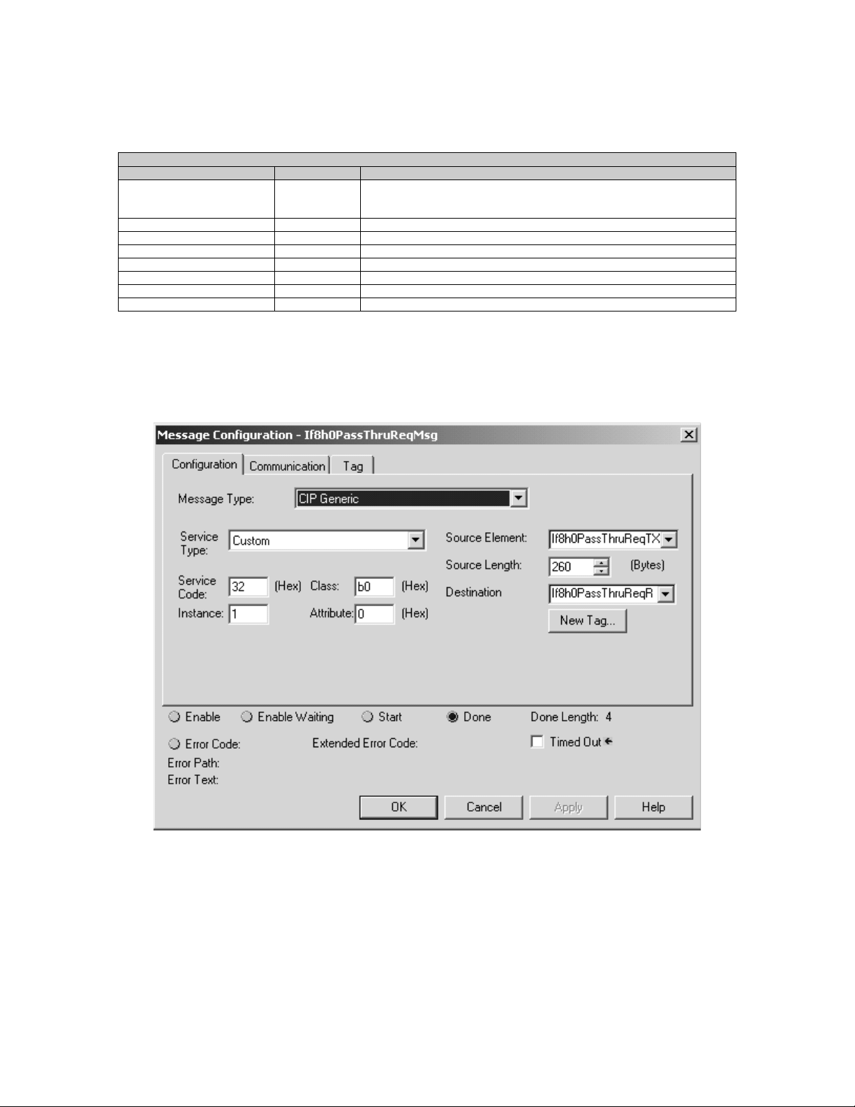
Chapter 7: HART Channel Configuration, Data, and Status 79
Table 7.6 (Generic CIP Configuration)
Field Value Definition
Message Type “CIP Generic” Control and Information Protocol (CIP) A native communications protocol used
Service Code 0x32
Class Name 0xB0
Instance Name 0x01
Object Attribute Leave blank
Source ? The tag defining the data sent to the HART module
Number of elements ? The number of elements defined by the command that is used
Destination ? The tag where the reply data will be written
Unconnected Message Header
on Allen-Bradley’s ControlNet communication network.
The MSG configuration screen is then loaded with the data from table 7.6.
See figure below.
Figure 7.8 (Message Configuration Dialog)
After the configuration screen is loaded with the data, the actual module
specific commands are loaded into the MSG source tag. When the MSG
instruction executes, the module specific command is passed to the module
via the MSG "source" tag and the reply data is passed to the MSG
"destination" tag. The module specific commands include, HART
suspension, HART resume, get device information, and the HART passthrough commands. The tables on the following pages show the format
for each module specific command.
Note: The source length should be large enough to accommodate the
HART message string.
Page 94
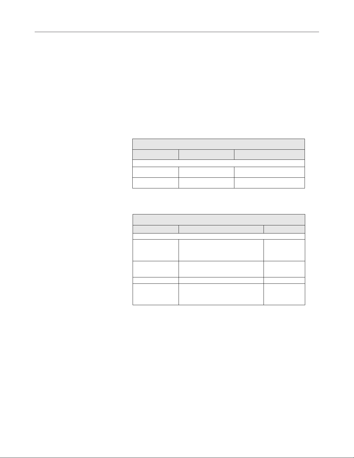
80 ControlLogix™ Analog HART Modules
Get HART Device Information
The Get HART Device Information command is used to gather the device
specific information for the connected HART device. The data that is
retrieved can be seen in table 7.7. The information that is gathered by this
command is similar to the information gathered from the auto-acquisition
process. The key difference is that the Get HART Device Information
command pulls the data that has been stored in the module RAM and not
directly from the field device.
Table 7.7 (Get HART Device Information Command)
HART Get Device Information – command message packet structure
Get currently cached Device Information for a given channel.
Field Value Definition
Unconnected Message Header
HART Channel
Number
Command Number 0x03 (1 byte) The command number to obtain
0x00 – 0x07 (1 byte) Module input channel number for
Table 7.8 (Response If Device Information Is Not Available)
HART Get Device Information - reply packet structure
Field Value Definition
Unconnected Message Header
HART Channel
Number
Status (1 byte)
Count (1 byte) Set to 1
Handle 0 Fill byte of zero to
0x00 – 0x07 (1 byte) Module input
34 = RUNNING
35 = DEAD (bad request)
HART command
HART device information
channel number
for HART
command
Command status
keep command
response common
among all replies.
Page 95

Chapter 7: HART Channel Configuration, Data, and Status 81
Table 7.9 (Response When Device Information Is Available)
HART Get Device Information - reply packet structure
Field Value Definition
Unconnected Message Header
HART Channel Number 0x00 – 0x07 (1 byte) Module input channel number for
Status 00 = SUCCESS Command status
Count (1 byte) Number of data bytes to following.
HARTManufacturerIDCode (1 byte) CMD#0, Byte 1
HARTDeviceTypeCode (1 byte) CMD#0, Byte 2
HARTPreambles (1 byte) CMD#0, Byte 3
HARTUnivCmdCode (1 byte) CMD#0, Byte 4
HARTTransSpecRev (1 byte) CMD#0, Byte 5
HARTSoftwareRevision (1 byte) CMD#0, Byte 6
HARTHardwareRevision (1 byte) CMD#0, Byte 7
HARTFlags (1 byte) CMD#0, Byte 8
HARTDeviceID (3 bytes) Device serial number CMD#0, Bytes 9-11
HARTTag (8 bytes unpacked ASCII) CMD#13, Bytes 0-5
HARTDescriptor (16 bytes unpacked ASCII) CMD#13, Bytes 6-17
HARTDate (3 bytes) CMD#13, Bytes 18-20
HARTFinalAssemblyNumber (3 bytes) CMD#16, Bytes 0-2
HARTMessage (32 bytes unpacked ASCII) CMD#12, Bytes 0-23
HARTPVCode (1 byte) CMD#50, Bytes 0
HARTSVCode (1 byte) CMD#50, Bytes 1
HARTTVCode (1 byte) CMD#50, Bytes 2
HARTFVCode (1 byte) CMD#50, Bytes 3
HARTPVUnits (1 byte) CMD#3, Byte 4
HARTSVUnits (1 byte) CMD#3, Byte 9
HARTTVUnits (1 byte) CMD#3, Byte 14
HARTFVUnits (1 byte) CMD#3, Byte 19
HARTPVLowerRange (4 bytes – Floating Point Value) CMD#15, Bytes 3-6
HARTPVUpperRange (4 bytes – Floating Point Value) CMD#15, Bytes 7-10
HART command
0 if not present
0 if not present
0 if not present
The command status, the second byte in the reply packet for the module
specific command, can return three different responses, SUCCESS,
RUNNING and DEAD. These responses echo the state of the module at
the time the command is sent. The conditions for each response are as
follows:
SUCCESS will be sent back when all of the following conditions are
met:
• Command and HART Channel number are both valid.
• HART channel device information is available.
RUNNING will be sent back when all of the following conditions
are met:
Page 96

82 ControlLogix™ Analog HART Modules
• Command and HART Channel number are both valid.
• HART channel is enabled and communication has been established,
meaning at least the device addressing information is available.
• HART channel is already in the state of gathering device information.
Reply will be sent back without additional events triggered.
DEAD will be sent back if any of the following conditions is true:
• Command or HART Channel number is invalid
• HART channel is not enabled
• HART communication has not been established, meaning that the 5byte unique address has not been determined yet.
• All other conditioned not generating RUNNING or SUCCESS.
The following figure demonstrates how a module specific command can
be sent to the module using ladder logic.
Figure 7.9 (Sending a Module Specific Command Using Ladder)
HART Channel Suspension and Resume
Sometimes referred to as "Out of Service" and "In Service" respectively,
these commands can be utilized to suspend or resume operation of an
enabled HART channel. When a HART Suspend Channel command is
sent, the HART module will keep the current HART configuration
information and stop all communication processes on the selected channel.
However, there will be overriding conditions such as configuration change
affecting the overall module operation, which will cause the HART
function to reset based on the new configuration. Normal HART
operation will resume if the HART Resume command is sent to the
module during a HART Suspension.
Page 97

Chapter 7: HART Channel Configuration, Data, and Status 83
Note: If the resume command is received, without previously receiving a
suspension command, it will be ignored.
Note: The selected channel will resume normal HART operations three
minutes after the Suspension command has been received by the module.
Pass-through for that channel resets the timer to 3 minutes.
Table 7.10 (HART Suspend and Resume Command)
HART Channel Suspend/Resume command request – command message packet structure
Field Value Definition
Unconnected Message Header
HART Channel Number 0x00 – 0x07 (1 byte) Enabled HART channel
Command Number (1 byte)
0x05: Suspend
0x06: Resume
number
The command number to
suspend or resume
Table 7.11 (HART Suspend and Resume Reply Packet)
HART Channel Suspend/Resume command request – reply packet structure
Field Value Definition
Unconnected Message Header
HART Channel Number 0x00 – 0x07 (1 byte) Echo of the HART channel
Status (1 byte)
Count (1 byte) Set to 1
Handle 0 Fill byte of zero to keep
number received
Command status
00 = SUCCESS
35 = DEAD
command response common
among all replies.
The command status, the second byte in the reply packet for the module
specific command, can return two different responses, SUCCESS, and
DEAD. These responses echo the state of the module at the time the
command is sent. The conditions for each response are as follows:
SUCCESS will be sent back under the following conditions:
• Command and HART Channel number are both valid.
• HART channel number is an enabled channel
• The identified HART channel finished all of the start-up connection
process.
• The I/O module will not be checking for matching set of suspend/
resume commands. This means, if already suspended, and receives
another suspend, SUCCESS will be returned still. Similarly if the
system is operating as normal, and receives a resume command, it will
Page 98

84 ControlLogix™ Analog HART Modules
ignore the command and continue operation. This state of operation
will not be maintained after power-up or when configuration changes.
DEAD will be sent back if any of the following conditions is true:
• Command and HART Channel number are both valid.
• HART channel is not enabled
• HART communication has not been established, meaning that the 5byte unique address has not been determined yet, or the module is still
obtaining device information.
• All other conditioned not generating SUCCESS.
HART Pass-Through Command
The HART Pass-Through Command can be used to send any HART
command including, universal, common practice or device specific, directly
to a field device. The module in this case could be considered a HART
bridge. There can be two (2) instances of a HART pass-through message
being serviced, meaning the pass-through message queue is 2 deep. The
HART pass-through response will be queued the moment the command is
received, if the queue spaces are not already in use, and be dispatched
after at least a full scan is done. In another word, after servicing a passthrough, the HART module will make sure all enabled HART channels
have updated variable values before another pass-through is placed into
service.
All HART pass-through commands require a series of messages to be
exchanged. First, a pass-through command request must be sent to the
HART module to initiate the pass-through command. The HART module
will respond to the command request with a command request reply that
includes a handle that can be used to obtain the pass-through message
response. Once the handle is received, the user may issue a Get
Command Query to obtain the status of the pass-through command and
the pass-through command response data, if it is available.
There is a handle timeout associated with the final reply message. After
the HART module obtains the requested information from the HART
device, it will start the HandleTimeout (as defined in the Configuration
Tag) timer. The reply message will be kept persistent during the
HandleTimeout period. When the timeout occurs the reply message will
be discarded, and another pass through message will be serviced without
being rejected. The user defined Handle-Timeout is in the range of 1 to
255 seconds.
Page 99

Chapter 7: HART Channel Configuration, Data, and Status 85
Attention: If the HART message being sent orAttention: If the HART message being sent or
Attention: If the HART message being sent or
Attention: If the HART message being sent orAttention: If the HART message being sent or
!
received using the pass-through command containsreceived using the pass-through command contains
received using the pass-through command contains
received using the pass-through command containsreceived using the pass-through command contains
floating point values, the order of the bytes must befloating point values, the order of the bytes must be
floating point values, the order of the bytes must be
floating point values, the order of the bytes must befloating point values, the order of the bytes must be
reversed.reversed.
reversed.
reversed.reversed.
Depending on the HART command, the data contained within the HART
message may include floating point numbers or double integers. If a
floating point or double integer is contained within the HART message, the
user must be aware that the order of the bytes that make up the float or
double will need to be reversed. The reason for this is related to how the
bytes are stored in the Controllogix processor. The Controllogix processor
stores the bytes in memory in a format referred to as "big-endian". Bigendian is an order in which the "big end" (most significant value in the
sequence) is stored first (at the lowest storage address). However,
HART devices transmit the byte data in the reverse order or as you may
have guessed "little-endian" Refer to chapter 8 for a ladder sample
demonstrating the process of swapping the order of the bytes.
Table 7.12 (HART Pass-Through Command Request)
HART pass through command request – command message packet structure
Field Value Definition
Unconnected Message Header
HART Channel Number 0x00 – 0x07 (1 byte) Module input channel
Command Number 0x01 (1 byte) The command number
HART Command N bytes
N = Length of message – 2
Contents are as follows:
Start or Delimiter (1 byte): 0x82
Long form Address (5 bytes)
Command number (1 byte)
Request Data Count (1 byte)
Data (“Request Data Count” bytes)
Checksum (XOR of all bytes from delimiter on.
Delimiter is included )
number for HART
command
to issue a HART passthrough command.
The actual HART
command PDU
Page 100

86 ControlLogix™ Analog HART Modules
Table 7.13 (HART Pass-Through Command Request Reply)
HART pass through command request – reply packet structure
Field Value Definition
Unconnected Message Header
HART Channel Number 0x00 – 0x07 (1 byte) Module input channel
Status (1 byte)
Count (1 byte) Set to 1
Handle (1 byte)
33 = INITIATE
35 = DEAD (bad request)
0 (bad when status is DEAD)
1-255 (good)
The command status, the second byte in the reply packet for this module
specific command, can return two different responses, INITIATE, and
DEAD. These responses echo the state of the module at the time the
command is sent. The conditions for each response are as follows:
INITIATE will be sent back under the following conditions:
number for HART
command
Command status
The handle for
command complete
query
• Command and HART Channel number are both valid.
• HART channel is enabled and communication has been established,
meaning at least the device addressing information is available.
• Handle is available, meaning no pending handle is still active.
• HART channel is doing regular data sampling only. No pending device
information gathering is active.
• No pending pass-through handle is active, meaning handle timeout has
not occurred yet.
• Device address and delimiter are valid.
• Received CIP word count is large enough for the entire command
packet.
DEAD will be sent back if any of the following conditions are true:
• Command or HART Channel number is invalid
• HART channel is not enabled
• HART communication has not been established, meaning that the 5byte unique address has not been determined yet.
• The channel is currently updating device information. Theoretically,
pass-through command can be safely accepted after successfully
 Loading...