

Page 1

Owner’s Guide 0300199-01 Rev . B
C
ONTROL
C
OUNTER
Catalog Number: 1756sc-CTR8
L
OGIX
M
ODULE
™
Page 2

Page 3

Important Notes
1. Please read all the information in this owner’s guide before installing
the product.
2. The information in this owner's guide applies to hardware version A
and firmware version 2.0 or later.
3. This guide assumes that the reader has a full working knowledge of the
relevant processor.
Notice
The products and services described in this owner's guide are useful in a
wide variety of applications. Therefore, the user and others responsible
for applying the products and services described herein are responsible
for determining their acceptability for each application. While efforts
have been made to provide accurate information within this owner's
guide, Spectrum Controls assumes no responsibility for the accuracy,
completeness, or usefulness of the information herein.
Under no circumstances will Spectrum Controls be responsible or liable
for any damages or losses, including indirect or consequential damages
or losses, arising out of either the use of any information within this
owner's guide or the use of any product or service referenced herein.
No patent liability is assumed by Spectrum Controls with respect to the
use of any of the information, products, circuits, programming, or
services referenced herein.
The information in this owner's guide is subject to change without notice.
Limited Warranty
Spectrum Controls warrants that its products are free from defects in
material and workmanship under normal use and service, as described in
Spectrum Controls literature covering this product, for a period of 1 year.
The obligations of Spectrum Controls under this warranty are limited to
replacing or repairing, at its option, at its factory or facility, any product
which shall, in the applicable period after shipment, be returned to the
Spectrum Controls facility, transportation charges prepaid, and which
after examination is determined, to the satisfaction of Spectrum Controls,
to be thus defective.
This warranty shall not apply to any such equipment which shall have
been repaired or altered except by Spectrum Controls or which shall
have been subject to misuse, neglect, or accident. In no case shall the
liability of Spectrum Controls exceed the purchase price. The
aforementioned provisions do not extend the original warranty period of
any product which has either been repaired or replaced by Spectrum
Controls.
Page 4

Page 5

Who Should Use
This Guide
Preface
Read this preface to familiarize yourself with the rest of the owner’s
guide. This preface covers:
• who should use this guide
• what this guide covers
• related Allen-Bradley documents
• terms & abbreviations you should know
Use this guide if you design, install, program, or maintain a control system
that uses Allen-Bradley ControlLogix Controllers.
Y ou should have a basic understanding of ControlLogix products. Y ou
should also understand electronic process control and the ladder program
instructions required to generate the electronic signals that control your
application. If you do not, contact your local Allen-Bradley representative
for the proper training before using these products.
What This Guide
Covers
Related AllenBradley Documents
This guide covers the 1756sc-CTR8 counter/flow module. It contains the
information you need to install, wire, use, and maintain these modules. It
also provides diagnostic and troubleshooting help should the need arise.
T able A lists several Allen-Bradley documents that may help you as you
use these products.
Table A. Related Allen-Bradley documents
Allen-Bradley Doc. No. Title Publication Number
1756-P A72, ControlLogix Power Supply Installation
-PB72 Instructions 1756-5.1
1756-A4, ControlLogix Chassis Installation Instructions 1756-5.2
-A7, -A10,
-A13, -A17
Page 6

vi ControlLogix™ Counter Module
1756 Series ControlLogix Module Installation Instructions
(Each module has separate document for installation) 1756-5.5,
1756-L1, Logix5550 Controller User Manual 1756-6.5.12
-L1M1, -L1M2
1756-DHRIO ControlLogix Data Highway Plus
Communication Interface Module User Manual 1756-6.5.2
1756-ENET ControlLogix Ethernet Communication Interface
Module User Manual 1756-6.5.1
T o obtain a copy of any of the Allen-Bradley documents listed, contact
your local Allen-Bradley office or distributor .
Terms &
Abbreviations You
Should Know
Y ou should understand the following terms and abbreviations before using
this guide.
-5.42
A/C - Refers to alternating current. This is a sine wave signal that is
typically associated with magentic pickup flowmeters.
Attenuation – The reduction in magnitude of a signal as it passes through
a system. The opposite of gain.
Channel – Refers to one of eight, small-signal analog input interfaces to
the module’s terminal block. Each channel is configured for connection to
a input device, and has its own configuration and status words.
Chassis – See rack.
Common mode rejection ratio (CMRR) - The ratio of a device’s
differential voltage gain to common mode voltage gain. Expressed in dB,
CMRR is a comparative measure of a device’s ability to reject
interference caused by a voltage common to its terminal relative to
ground.
Common mode voltage – The voltage difference between the negative
terminal and analog common during normal differential operation.
Cut-off frequency - The frequency at which the input signal is attenuated
3 dB by the digital filter. Frequency components of the input signal that
are below the cut-off frequency are passed with under 3 dB of attenuation
for low-pass filters.
Page 7

Preface vii
DC - Direct Current - This is typically associated with a DC squarewave pulse signal from a flowmeter.
dB (decibel) – A logarithmic measure of the ratio of two signal levels.
Digital filter - A low-pass mathmatic single order filter applied to the
signal. The digital filter provides high-frequency noise rejection.
Effective resolution – The number of bits in the channel data word that
do not vary due to noise.
Local System - A control system with I/O chassis within several feet of
the processor.
LSB (least significant bit) – The bit that represents the smallest value
within a string of bits.
Normal mode rejection (differential mode rejection) – A logarithmic
measure, in dB, of a device’ s ability to reject noise signals between or
among circuit signal conductors, but not between the equipment grounding
conductor or signal reference structure and the signal conductors.
Module update time – See channel update time.
Remote system - A control system where the chassis can be located
several thousand feet from the processor chassis. Chassis communication
is via the 1756-DHRIO and 1756-ENET Adapter.
Resolution – The smallest detectable change in a measurement, typically
expressed in engineering units (e.g. 0.15 °C).
Sampling time - The time required by the mocule to sample an input
channel.
Step response time – The time required for the module to reach 95% of
its expected, final value, given a full-scale step change in the output data
word.
Tags - Identifiers for configuration, data, and status information found
withing the module. T ags allow the user to modify specific module
attributes and view data and status.
Update time – The time for the module to sample and convert a channel
input signal and make the resulting value available to the ControlLogix
processor.
Page 8

viii ControlLogix™ Counter Module
Page 9

Table of Contents
T able of Contents ix
Preface v
Chapter 1
Module Overview
Chapter 2
Installing Your
Module
Chapter 3
Operation in the
System
Who Should Use This Guide ...................................................................................v
What This Guide Covers.......................................................................................... v
Related Allen-Bradley Documents ........................................................................... v
T able A. Related Allen-Bradley documents ............................................................. v
Terms & Abbreviations You Should Know............................................................. vi
General Description .................................................................................................. 1
Table 1.1 Hardware Features .................................................................................... 2
System Overview...................................................................................................... 2
Cables ....................................................................................................................... 3
Installing And Wiring Your Module ........................................................................ 1
Electrostatic Damage ................................................................................................ 1
Power Requirements................................................................................................. 2
Module Installation and Removal ............................................................................ 2
Wiring Your Module ................................................................................................6
Wiring Single-ended Inputs ..................................................................................... 7
Wiring Bi-Directional or Quadrature Inputs ............................................................ 8
Operation Within the
ControlLogix System .............................................................................................. 17
Ownership and Connections .................................................................................. 17
Using RSNetW orx and RSLogix 5000..................................................................... 17
Direct Connections ................................................................................................. 18
Module Operation .................................................................................................. 18
Modules in a Local Chassis ................................................................................... 18
Requested Packet Interval (RPI) ............................................................................ 19
Modules in a Remote Chassis................................................................................ 19
Listen-Only Mode .................................................................................................. 20
Multiple Owners of Input Modules ....................................................................... 20
Configuration Changes in an Input Module with Multiple Owners...................... 21
Chapter 4
Programming Your
Module
Module Installation ................................................................................................ 23
Adding Your Module to a Project .......................................................................... 23
Page 10

x ControlLogix™ Counter Module
Chapter 5
Configuring module
attributes:
Configuration, Data,
and Status Tags ...................................................................................................... 31
Send Configuration Data to the Module ................................................................ 31
Configuration Tags................................................................................................. 32
Channel Specific Settings ....................................................................................... 32
Output Tags ............................................................................................................ 37
Input Tags .............................................................................................................. 37
Chapter 6
Programming
Examples
Initial Programming................................................................................................. 39
Figure 5.1 Sample Ladder Logic ............................................................................. 40
Using the gate storage mode ................................................................................. 42
Installation Recommendations ............................................................................... 44
Meter Proving ......................................................................................................... 45
Chapter 7
Troubleshooting
Using Module Indicators to Troubleshoot............................................................ 45
Using RSLogix 5000 to Troubleshoot Your Module.............................................. 46
Module Configuration Errors ................................................................................. 47
Chapter 8
Maintaining Your
Module
Appendix A
Module
Specifications
Appendix B
Programming Your
Module
Preventive Maintenance ........................................................................................ 49
Safety Considerations ............................................................................................ 49
Electrical Specifications.......................................................................................... 53
Environmental Specifications ................................................................................. 54
Input Specifications ............................................................................................... 54
Accuracy ................................................................................................................ 54
Module Installation ................................................................................................ 57
Adding Your Module to a Project .......................................................................... 57
Declaration of Conformity ...................................................................................... 64
Page 11

Chapter 1
Module Overview
This chapter describes the counter module and explains how the
ControlLogix controller reads analog input data from the module. Read
this chapter to familiarize yourself further with your counter module. This
chapter covers:
• general description and hardware features
• an overview of system and module operation
General Description
This module is designed exclusively for use in the Allen-Bradley
ControlLogix 1756 I/O rack systems. The module reads AC and DC
pulse information from external sensors and stores it in its image table for
retrieval by all ControlLogix processors.
Following is a list of features available on the CTR8 module that allow
their use in a wide variety of applications.
· Removal and insertion under power (RIUP) - a system feature that
allows you to remove and insert modules while chassis power is applied
· Producer/consumer communications - an intelligent data exchange
between modules and other system devices in which each module
produces data without having been polled
· System timestamp of data - 64 bit system clock places a timestamp on
the transfer of data between the module and its owner controller within
the local chassis
· IEEE 32 bit floating point format
· On-Board Features, such as custom User Scaling, Analog and Digital
Filtering, and Under/Over Detection
· Class I/Division 2, UL, CUL, CE, and FM Agency Certification
Page 12

2 ControlLogix™ Counter Module
Input Types
The 1756-CTR supports both AC and DC input signal types. The module
input type is configured on a channel pair basis. Each pair must be
configured for the same input type.
Hardware Features
The module fits into any single slot for I/O modules in a ControlLogix
modular system. The module has a unique generic profile which may be
configured using your RSLogix 5000 programming software.
The module utilizes one removable terminal block, that provides
connections for the eight input channels. The module is configured
through RSLogix 5000 software, defining input type, counter control and
signal filtering.
Table 1.1 Hardware Features
System Overview
Hardware Function
OK LED Displays communication and fault status of the module
SYS LED Displays a fault condition
Side Label (Nameplate) Provides module information
Removable T erminal Block Provides electrical connection to input devices
Door Label Permits easy terminal identification
Self Locking T abs Secure module in chassis slot
Terminal Block Switch Locks the R TB to the module.
Diagnostic LEDs
The module contains diagnostic LEDs that help you identify the source of
problems that may occur during power-up or during normal operation.
Power-up and diagnostics are explained in Chapter 7, Testing Your
Module.
The module communicates with the ControlLogix processor and receives
+5 Vdc and +24 Vdc power from the system power supply through the
parallel backplane interface. You may install as many counter modules in
the system as the power supply can support.
Channels (0 through 7) can receive AC or DC input signals. Input types
must be configured in channel pairs. Each channel reports both count data
and rate data in independent registers. Extended status information is also
available for each channel.
Page 13

Chapter 1: Module Overview 3
System Operation
At power-up, the module checks internal circuits, memory , and basic
functions. During this time the SYS LED remains on. If the module does
not find any faults, it turns off the SYS LED.
After completing power-up checks, the module wait for a connection to an
owner controller then valid channel configuration data from your ladder
logic program. After channel configuration data is transferred, and one or
more channels are enabled, the module continuously converts the inputs to
floating point data for use in your ladder program.
Each time the module reads an input channel, the module tests that data
for a fault, i.e. signal mismatch, or out of range condition. If it detects an
error condition, the module sets a unique bit in the status tags.
Module Operation
The module’s input circuitry consists of eight single-ended inputs, routed
into an FPGA. The FPGA reads the input signals and converts them to
counter and rate and then presents them in floating point values.. The
input circuitry also supports gate inputs allowing you to disable and control
counter operation.
ables
C
Cable length should be kept to a minimum. Use the lowest capacitance
shielded cable available. We recommend that you use Belden #9501 (or
equivalent).
Table 1.2 Cable Specifications
Description Belden #9501
When used? AC/DC inputs.
Conductors 2, #24 A WG tinned copper (7x32)
Shield Beldfoil aluminum polyester shield w/ copper drain wire. .
Insulation PVC
Jacket Chrome PVC
Agency NEC Type CM
Approval
Temperature 80°C
Rating
Page 14

4 ControlLogix™ Counter Module
Page 15

Electrostatic
Damage
Installing And Wiring Y our Module
Read this chapter to install and wire your module. This chapter covers:
• avoiding electrostatic damage
• determining power requirements
• installing the module
• wiring signal cables to the module’s terminal block
Electrostatic discharge can damage semiconductor devices inside this
module if you touch backplane connector pins. Guard against
electrostatic damage by observing the following precautions:
CAUTION
Power
Requirements
ELECTROSTATICALLY SENSITIVE COMPONENTS
• Before handling the module, touch a grounded
object to rid yourself of electrostatic charge.
• When handling the module, wear an approved wrist strap
grounding device.
• Handle the module from the front, away from the
backplane connector. Do not touch backplane connector pins.
• Keep the module in its static-shield container when not in use or
during shipment.
Failure to observe these precautions can degrade the module’s
performance or cause permanent damage.
The module receives its power through the ControlLogix chassis
backplane from the fixed or modular +5 VDC and +24 VDC chassis
power supply . The maximum current drawn by the module is shown in
the table below .
Table 2.1. Maximum current drawn by the module
5VDC Amps 24VDC Amps
0.230 0.075
Page 16

Using your module in the ControlLogix System
Place your module in any slot of a ControlLogix modular, or modular
expansion chassis.
An analog I/O module translates an analog signal into, or from, a
corresponding digital representation which controllers can easily operate
on for control purposes.
A ControlLogix I/O module mounts in a ControlLogix chassis and uses a
Removable T erminal Block (R TB) to connect all field-side wiring.
Before you install and use your module you should have already:
· installed and grounded a 1756 chassis and power supply.
· ordered and received an RTB for your application.
Important: RTBs are not included with your module purchase.
Specify Allen Bradley Part Number:
1756-TBCH - 36 position screw terminals
1756-TBS6H - 36 position press terminals
Module Installation
and Removal
When installing the module in a chassis, it is not necessary to remove the
terminal blocks from the module. However, if the terminal blocks are
removed, use the write-on label located on the side of the terminal blocks
to identify the module location and type.
Preventing Electrostatic Discharge
This module is sensitive to electrostatic discharge.
ATTENTION: Electrostatic discharge can damage integrated
circuits or semiconductors if you touch backplane connector pins.
Follow these guidelines when you handle the module:
· Touch a grounded object to discharge static potential
· Wear an approved wrist-strap grounding device
· Do not touch the backplane connector or connector pins
· Do not touch circuit components inside the module
· If available, use a static-safe work station
· When not in use, keep the module in its static-shield box
Page 17

Removal and Insertion Under Power
These modules are designed to be installed or removed while chassis
power is applied.
ATTENTION: When you insert or remove a module while backplane
power is applied, an electrical arc may occur. An electrical arc can
cause personal injury or property damage by:
· sending an erroneous signal to your system’s field devices
causing unintended machine motion or loss of process control.
· causing an explosion in a hazardous environment.
Repeated electrical arcing causes excessive wear to contacts on
both the module and its mating connectors. Worn contacts may
create electrical resistance that can affect module operation.
Compliance to European Union Directives
If this product bears the CE marking, it is approved for installation within
the European Union and EEA regions. It has been designed and tested to
meet the following directives.
EMC Directive
This product is tested to meet Council Directive 89/336/EEC
Electromagnetic Compatibility (EMC) and the following standards, in
whole or in part, documented in a technical construction file:
EN 61010-1 and EN 61131-2, EN61000-6-2:2001, EN61000-6-4:2001
EN61010-1:2001
This product is intended for use in an industrial environment.
Low Voltage Directive
This product is tested to meet Council Directive 73/23/EEC Low Voltage,
by applying the safety requirements of EN 61131-2 Programmable
Controllers, Part 2 - Equipment Requirements and T ests.
For specific information required by , EN61131-2:1994 + A11:1996 +
A12:2000, see the appropriate sections in this publication, as well as the
following Allen-Bradley publications:
· Industrial Automation Wiring and Grounding Guidelines For Noise
Immunity, publication 1770-4.1
· Automation Systems Catalog, publication B1 1 1
Page 18
This equipment is classified as open equipment and must be installed
(mounted) in an enclosure during operation as a means of providing
safety protection.
CAUTION
POSSIBLE EQUIPMENT OPERATION
ATTENTION: The module is designed to support Removal and
Insertion Under Power (RIUP). However, when you remove or
insert an RTB with field-side power applied, unintended machine
motion or loss of process control can occur. Exercise extreme
caution when using this feature.
ATTENTION: Counter input isolated secondary circuits must be
energy limited and limited to not source more than 5.8 amp into
either the Counter inputs or the Gate inputs in the event of a
component failure
WARNING
The 1756sc-CTR8 module is to be used only with the Allen-Bradley
1756 ControlLogix System.
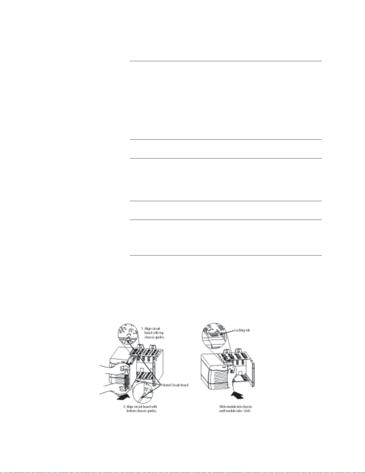
T o insert your module into the rack, follow these steps:
1. Align the circuit board of your module with the card guides at the top
and bottom of the chassis.
Figure 2.1. Module insertion into a rack
Page 19

2. Key the R TB in positions that correspond to unkeyed module
positions. Insert the wedge-shaped tab on the R TB with the rounded
edge first. Push the tab onto the R TB until it stops.
Keying the Removable Terminal Block
Key the RTB to prevent inadvertently connecting the incorrect RTB to
your module.
When the RTB mounts onto the module, keying positions will match up.
For example, if you place a U-shaped keying band in position #4 on the
module, you cannot place a wedge-shaped tab in #4 on the R TB or your
RTB will not mount on the module.
W e recommend that you use a unique keying pattern for each slot in the
chassis.
1. Insert the U-shaped band with the longer side near the terminals. Push
the band onto the module until it snaps into place.
Figure 2.2. Terminal block diagram with keying
Wiring Your Module
Follow these guidelines to wire your input signal cables:
• Power, input, and output (I/O) wiring must be in accordance with
Class 1, Division 2 wiring methods [Article 501-4(b) of the National
Electrical Code, NFP A 70] and in accordance with the authority having
jurisdiction.
• Peripheral equipment must be suitable for the location in which it is
used.
• Route the field wiring away from any other wiring and as far as
possible from sources of electrical noise, such as motors, transformers,
contactors, and ac devices. As a general rule, allow at least 6 in. (about
15.2 cm) of separation for every 120 V of power.
• Routing the field wiring in a grounded conduit can reduce electrical
noise further.
Page 20

• If the field wiring must cross ac or power cables, ensure that they
cross at right angles.
• To limit the pickup of electrical noise, keep signal wires as far from
power and load lines as possible.
• Ground the shield drain wire at only one end of the cable. The
preferred location is at the shield connections at the ControlLogix
chassis. (Refer to IEEE Std. 518, Section 6.4.2.7 or contact your sensor
manufacturer for additional details.)
• Tighten screw terminals with care. Excessive tightening can strip a
screw.
• Follow system grounding and wiring guidelines found in your
ControlLogix Installation and Operation Manual.
Preparing and Wiring the Cables
T o prepare and connect cable leads and drain wires, follow these steps:
Signal Wires
(At the module-end of the cable, extract
the drain wire but remove the foil shield.)
1. At each end of the cable, strip some casing to expose individual
wires.
2. Trim signal wires to 5-inch lengths beyond the cable casing. Strip
about 3/16 inch (4.76 mm) of insulation to expose the ends of the wires.
3. At the module-end of the cables (see figure above):
- extract the drain wire and signal wires
- remove the foil shield
- bundle the input cables with a cable strap
4. Connect pairs of drain wires together, Channels 0 and 1, Channels 2
and 3, Channels 4 and 5, Channels 6 and 7. Keep drain wires as short as
possible.
Drain Wire
Cable
(Remove foil shield and drain wire
from sensor-end of the cable.)
Signal Wires
5. Connect the drain wires to the grounding lug on the PLC chassis.
6. Connect the signal wires of each channel to the terminal block.
Important: Only after verifying that your connections are correct for
each channel, trim the lengths to keep them short. Avoid cutting leads
too short.
7. At the source-end of cables from devices:
- remove the drain wire and foil shield
- apply shrink wrap as an option
- connect to mV devices keeping the leads short
Page 21
Wiring Single-ended
0
3
Inputs
Important: If noise persists, try grounding the opposite end of the cable,
instead (Ground one end only.)
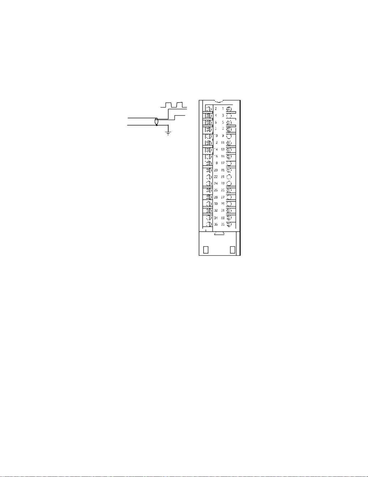
The following figure shows the general terminal block layout. A single-ended input uses a pair of
terminals, Hi(x) and Com. Gate lines are wired with their respective Gate(x) and Com terminals.
Single-ended Wiring
Unidirecti onal I nput
Chassis
Ground
Hi 4
Com
Gate 4
Com
Hi 5
Com
Gate 5
Com
Hi 6
Com
Gate 6
Com
Hi 7
Com
Gate 7
Com
N/C
N/C
Hi 0
Com
Gate
Com
Hi 1
Com
Gate 1
Com
Hi 2
Com
Gate 2
Com
Hi 3
Com
Gate
Com
N/C
N/C
Page 22

Wiring Bi-
g
Directional or
Quadrature Inputs
Input use channel pairs, for example Hi2(A), Com, Hi2(B), Com. There
is one gate input per channel pair.
Bi-directional/Quadrature Wirin
Bi-directional Input
Chassis
Ground
Quadrature Input
Chassis
Ground
A
Z
B
Hi 3 (A)
Com
Gate 3
Com
Hi 3 (B)
Com
N/C
Com
Hi 4 (A)
Com
Gate 4
Com
Hi 4 (B)
Com
N/C
N/C
N/C
N/C
Hi 0 (A)
Com
Gate 0
Com
Hi 0 (B)
Com
N/C
Com
Hi 1 (A)
Com
Gate 1
Com
Hi 1 (B)
Com
N/C
N/C
N/C
N/C
Page 23

Page 24

Ownership and
Connections
Chapter 3
Operation Within the
ControlLogix System
This chapter describes how the 1756sc-CTR8 analog module works
within the ControlLogix system. This chapter covers:
• Ownership and connections to the module
• Direct connections
• Listen only mode
• Configuration changes with multiple owners.
Every I/O module in the ControlLogix system must be owned by a
Logix5550 Controller to be useful. This owner-controller stores
configuration data for every module that it owns and can be local or
remote in regard to the I/O module’s position. The owner sends the I/O
module configuration data to define the module’ s behavior and begin
operation within the control system. Each ControlLogix I/O module must
continuously maintain communication with its owner to operate normally.
Using RSNetWorx
and RSLogix 5000
T ypically , each module in the system will have only 1 owner . Input
modules can have more than 1 owner . Output modules, however , are
limited to a single owner.
The I/O configuration portion of RSLogix5000 generates the
configuration data for each I/O module in the control system, whether
the module is located in a local or remote chassis. A remote chassis, also
known as networked, contains the I/O module but not the module’s
owner controller . Configuration data is transferred to the controller during
the program download and subsequently transferred to the appropriate I/
O modules. I/O modules in the same chassis as the controller are ready
to run as soon as the configuration data has been downloaded. You must
run RSNetW orx to enable I/O modules in the networked chassis.
Running RSNetW orx transfers configuration data to networked modules
and establishes a Network Update Time (NUT) for ControlNet that is
compliant with the desired communications options specified for each
module during configuration. If you are not using I/O modules in a
networked chassis, running RSNetW orx is not necessary. However,
anytime a controller references an I/O module in a networked chassis,
RSNetW orx must be run to configure ControlNet. Follow these general
guidelines when configuring I/O modules:
Page 25

DirectDirect
Direct
DirectDirect
ConnectionsConnections
Connections
ConnectionsConnections
Chapter 3: Operation within the System 15
1. Configure all I/O modules for a given controller using RSLogix 5000
and download that information to the controller .
2. If the I/O configuration data references a module in a remote chassis,
run RSNetWorx.
Important: RSNetWorx must be run whenever a new module is added
to a networked chassis. When a module is permanently removed from a
remote chassis, we recommend that RSNetWorx be run to optimize the
allocation of network bandwidth.
A direct connection is a real-time data transfer link between the
controller and the device that occupies the slot that the configuration data
references. When module configuration data is downloaded to an ownercontroller, the controller attempts to establish a direct connection to each
of the modules referenced by the data.
If a controller has configuration data referencing a slot in the control
system, the controller periodically checks for the presence of a device
there. When a device’ s presence is detected, the controller automatically
sends the configuration data. If the data is appropriate to the module
found in the slot, a connection is made and operation begins. If the
configuration data is not appropriate, the data is rejected and an error
message displays in the software. In this case, the configuration data can
be inappropriate for any of a number of reasons.
Module OperationModule Operation
Module Operation
Module OperationModule Operation
Modules in a Local
Chassis
The controller maintains and monitors its connection with a module. Any
break in the connection, such as removal of the module from the chassis
while under power, causes the controller to set fault status bits in the data
area associated with the module. The RSLogix 5000 software may
monitor this data area to announce the modules’ failures.
In traditional I/O systems, controllers poll input modules to obtain their
input status. Analog input modules in the ControlLogix system are not
polled by a controller once a connection is established. The modules
multicast their data periodically . Multicast frequency depends on the
options chosen during configuration and where in the control system that
input module physically resides. An input module’ s communication, or
multicasting, behavior varies depending upon whether it operates in the
local chassis or in a remote chassis. The following sections detail the
differences in data transfers between these set-ups.
When a module resides in the same chassis as the owner controller, the
following two configuration parameters will affect how and when the
input module multicasts data:
· Real Time Sample (RTS) configured via Real Time Sample tag.
· Requested Packet Interval (RPI) configured via I/O module properties.
Page 26

16 ControlLogix™ Counter Module
Requested Packet
Interval (RPI)
Real Time Sample (RTS)
This configurable parameter instructs the module to perform the
following operations:
1. scan all of its input channels and store the data into on-board memory
2. multicast the updated channel data (as well as other status data) to the
backplane of the local chassis
This configurable parameter also instructs the module to multicast its
channel and status data to the local chassis backplane.
The RPI instructs the module to multicast the current contents of its
on-board memory when the RPI expires, (i.e. the module does not
update its channels prior to the multicast).
Important: The RPI value is set during the initial module configuration
using RSLogix 5000.
Modules in a
Remote Chassis
It is important to note that the module will reset the RPI timer each time
an RTS is performed. This operation dictates how and when the owner
controller in the local chassis will receive updated channel data,
depending on the values given to these parameters. If the RTS value is
less than or equal to the RPI, each multicast of data from the module will
have updated channel information. In effect, the module is only
multicasting at the R TS rate.
If the R TS value is greater than the RPI, the module will multicast at
both the RTS rate and the RPI rate. Their respective values will dictate
how often the owner controller will receive data and how many
multicasts from the module contain updated channel data. Note: Even
though data may be transfered at the RPI rate, the data will be indentical
to the previous RTS data transfer.
If an input module resides in a networked chassis, the role of the RPI
and the module’s R TS behavior change slightly with respect to getting
data to the owner. The RPI and RTS intervals still define when the
module will multicast data within its own chassis (as described in the
previous section), but only the value of the RPI determines how often the
owner controller will receive it over the network.
When an RPI value is specified for an input module in a remote chassis,
in addition to instructing the module to multicast data within its own
chassis, the RPI also “reserves” a spot in the stream of data flowing
across the ControlNet network.
Page 27

Chapter 3: Operation within the System 17
The timing of this “reserved” spot may or may not coincide with the
exact value of the RPI, but the control system will guarantee that the
owner controller will receive data at least as often as the specified RPI.
The “reserved” spot on the network and the module’s RTS are
asynchronous to each other. This means there are Best and Worst Case
scenarios as to when the owner controller will receive updated channel
data from the module in a networked chassis.
Best Case RTS Scenario
In the Best Case scenario, the module performs an RTS multicast with
updated channel data just before the “reserved” network slot is made
available. In this case, the remotely located owner receives the data
almost immediately.
Worst Case RTS Scenario
In the W orst Case scenario, the module performs an RTS multicast just
after the “reserved” network slot has passed. In this case, the ownercontroller will not receive data until the next scheduled network slot.
Listen-Only Mode
Because it is the RPI and NOT the RTS which dictates when the
module’s data will be sent over the network, we recommend the RPI
value be set LESS THAN OR EQUAL TO the RTS to make sure that
updated channel data is received by the owner controller with each
receipt of data.
Any controller in the system can listen to the data from any I/O module
(e.g. input data or “echoed” output data) even if the controller does not
own the module (i.e. it does not have to hold the module’ s configuration
data to listen to the module).
The “listen only” mode is set during the I/O configuration process.
Choosing a ‘Listen-Only’ mode option allows the controller and module
to establish communications without the controller sending any
configuration data. In this instance, another controller owns the module
being listened to.
Important:Controllers using the Listen-Only mode continue to receive
data multicast from the I/O module as long as a connection between an
owner and I/O module is maintained. If the connection between all
owners and the module is broken, the module stops multicasting data and
connections to all ‘Listening controllers’ are also broken.
Multiple Owners of
Input Modules
Because ‘Listening controllers’ lose their connections to modules when
communications with the owner stop, the ControlLogix system will allow
you to define more than one owner for input modules.
Page 28

18 ControlLogix™ Counter Module
Important: Only input modules can have multiple owners. If multiple
owners are connected to the same input module, they must maintain
identical configuration for that module.
In the example below, Controller A and Controller B have both been
configured to be the owner of the input module.
When the controllers begin downloading configuration data, both try to
establish a connection with the input module. Whichever controller’s data
arrives first establishes a connection. When the second controller’s data
arrives, the module compares it to its current configuration data (the data
received and accepted from the first controller).
If the configuration data sent by the second controller matches the
configuration data sent by the first controller the connection is also
accepted. If any parameter of the second configuration data is different
from the first, the module rejects the connection and the user is informed
by an error in the software.
The advantage of multiple owners over a ‘Listen-only’ connection is that
now either of the controllers can lose the connection to the module and
the module will continue to operate and multicast data to the system
because of the connection maintained by the other owner controller.
Configuration
Changes in an
Input Module with
Multiple Owners
Note: The previous discussion of multiple owners assues the
configuration tag “.configrevnumber” is set to 1. Operation differs is the
tag is set to 0. Refer to Chapter 5 for descriptions of this tag’s settings.
Y ou must be careful when changing an input module’ s configuration data
in a multiple owner scenario. When the configuration data is changed in
one of the owners, for example, Controller A, and sent to the module,
that configuration data is accepted as the new configuration for the
module. Controller B will continue to listen, unaware that any changes
have been made in the module’ s behavior .
Important: When changing configuration for a module with multiple
owners, we recommend the connection be inhibited. T o prevent other
owners from receiving potentially erroneous data, as described above,
the following steps must be followed when changing a module’ s
configuration in a multiple owner scenario when online:
1. For each owner controller, inhibit the controller’s connection to the
module in the software on the I/O Module Connection tab.
2. Make the appropriate configuration data changes in the software.
Page 29

Chapter 3: Operation within the System 19
Page 30

Chapter 4
Programming Your Module
This chapter explains how to program your module in the ControlLogix
system. It also describes how the module’ s input configuration are
incorporated into your ladder logic program. T opics discussed include:
• importing the module’s configuration profile
• reviewing accessing and altering configuration options.
• configuring the modules input type and filter settings
• configuring alarms and limits
Module Installation
Adding Your Module
to a Project
Incorporating your module into the system is similar to adding any type of
I/O module. You will use your RSLogix 5000 programming software. The
module is not currently in the pick list of this software so you will drag and
drop sample information from a sample program. This allows you to
import the configuration database into your project and set the attributes of
each tag. These settings control features such as the modules input type,
channel input range, data format, filter frequency, etc.
Y ou will need to download the sample project from our website and then
import this into your project. Then you may access the controller tags to
configure the module once this process is complete.
The module has a unique set of tag definitions which are used to configure
specific features. Chapter 5, Channel Configuration, Data, and Status,
gives you detailed information about the data content of the configuration.
These values are set using your programming software and ladder logic.
Before you can use these feature you must first include the module into the
project.
Page 31

Chapter 4: Programming Y our Module 21
Step 1-
your project. Drag and drop the CTR8 module into the I/O configuration
section of your project.
1. Open the sample project.
2. Open your new project.
3. Click once on the CTR8 in the sample project.
4. Drag and drop it into the I/O Configuration section of your project.
See Appendix D for the I/O module property details.
Open the sample project with the CTR8 information. Open
Page 32
22 ControlLogix™ Counter Module
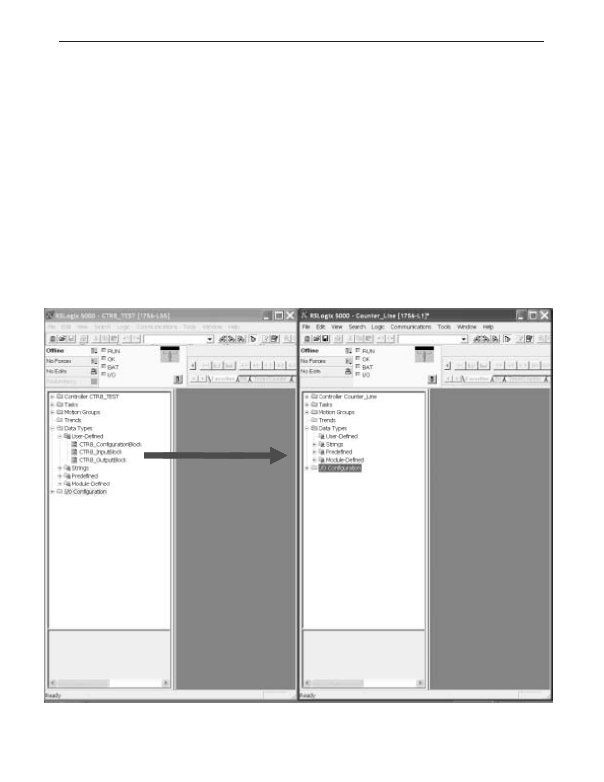
Step 2-
sample project into your project.
There are three CTR8 user defined data types that need to be moved.
ConfigurationBlock
InputBlock
OutputBlock
1. Click on the data type
2. Drag it into your new project.
3. Continue to drag and drop the data types until all four have been moved.
Note: These can only be moved one at a time.
Drag and drop the CTR8 user-defined data types from the
Page 33
Chapter 4: Programming Y our Module 23
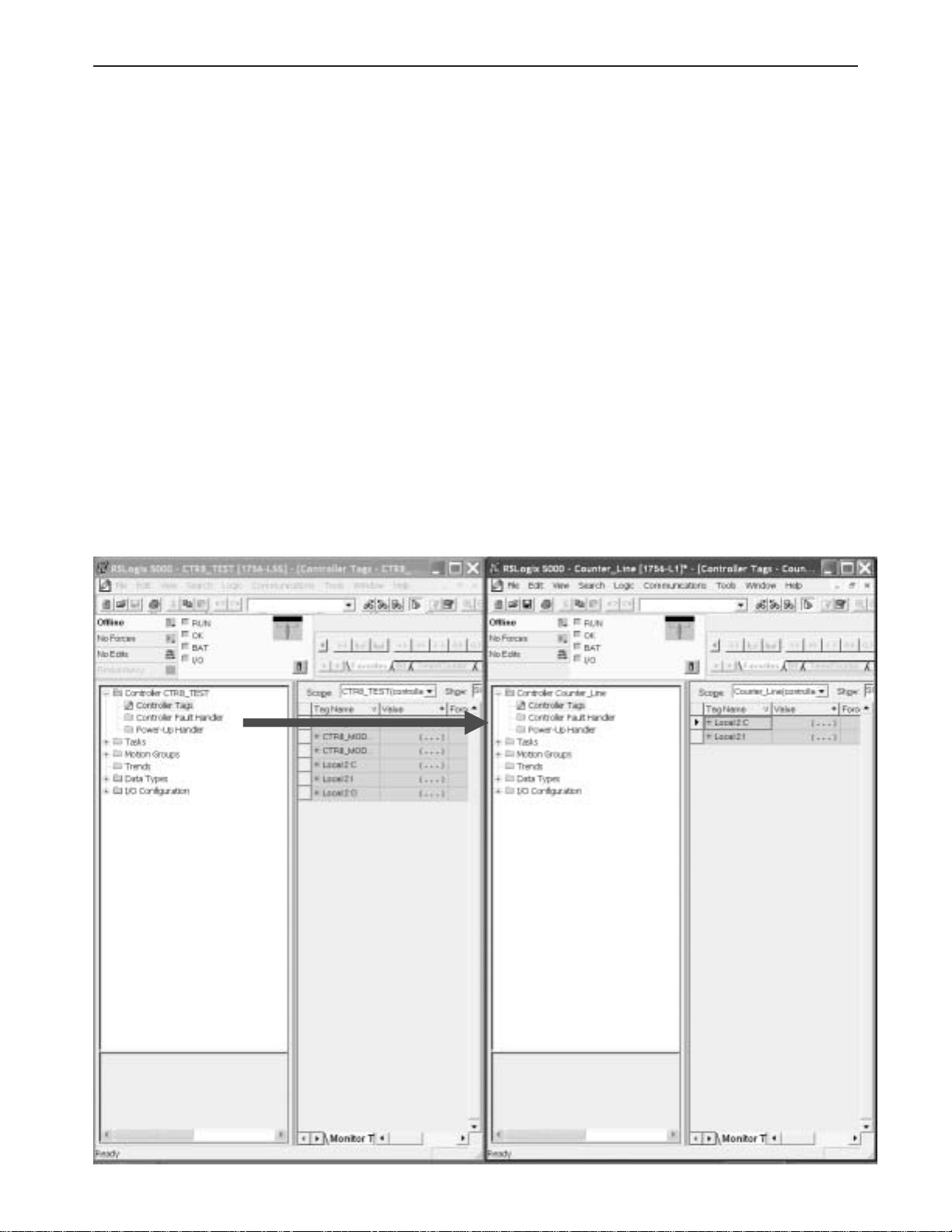
Step 3-
sample project into your project.
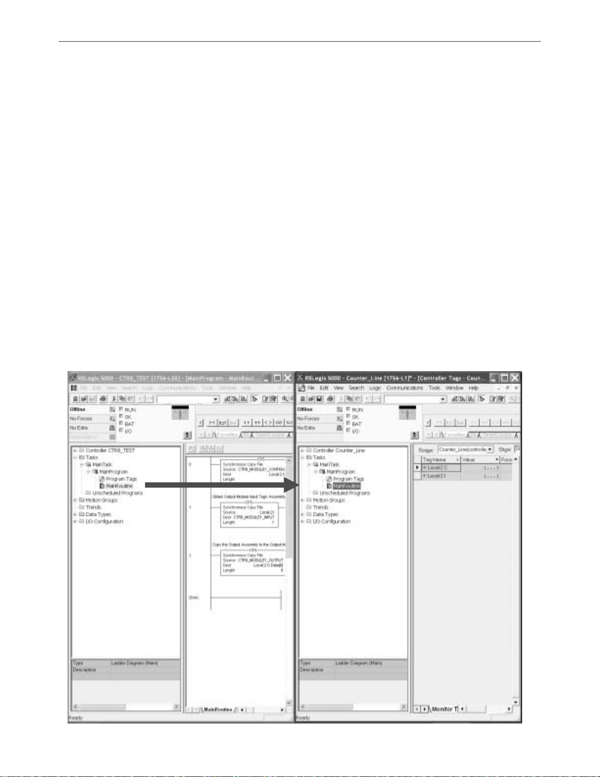
1. Right click on the Controller T ags item of the sample project and select
edit.
2. Right click on the Controller T ags item of your project and select edit.
3. Scroll down to the Controller tags of the sample project and select all the
tags by highlighting them.
4. Drag and drop these tags into your project.
Note: CTR8_Config and CTR8_Input contain the configuration, data and
status tags for the CTR8 module. The other tags are used for performing
various functions to your module via ladder logic.
Note: Be sure all tags are displayed before moving them. Select Display All
from the Edit drop down window .
Note: The “Local:3:I” and “Local:3:C” tags are not copied.
Drag and drop the controller configuration tags from the
Page 34
24 ControlLogix™ Counter Module
Step 4-
1. In your project, right mouse click on the MainRoutine item and select
“New Routine...” CTR8 was entered in the example above.
2. Double click on the MainRoutine item in the sample project and then
double click on the added new routine in your project to display their
corresponding ladder logic.
3. Left mouse inside the MainProgram ladder logic in the sample project
and press crtl-A to select all the rungs.
4. Drag and drop these rungs over and add them to the new routine’s ladder
logic. Note: You will need to delete the one blank “solid bar” rung either at
the top or bottom of the routine which was left over from the newly created
routine.
5. Now add a JSR ladder instruction in your MainRountine which calls this
routine.
Note: RSLogix 5000 will verify the ladder logic sample. You may receive
errors regarding invalid tags. Y ou will need to change the slot addressing in
the logic to coordinate with the location of the CTR8.
This completes the installation of module in the system
Create a new ladder logic routine in your project.
Page 35
Configuring module
attributes:
Configuration Tags
Chapter 4: Programming Y our Module 25
The module has settings that are global and channel specific. These are
accessed via the controller tags. Specific information regarding these tag
settings may be found in Chapter 5.
Channel Specific Tags
These settings control channel specific behavior such as input type, range,
filter frequency, units, and alarms. Specific information regarding these
tags may be found in Chapter 5.
Page 36

26 ControlLogix™ Counter Module
Data Tags
These tags represent the process data values in their final form.
Status Tags
These tags report module status such as alarm conditions, faults, and
errors.
Page 37

Chapter 4: Programming Y our Module 27
Page 38

28 ControlLogix™ Counter Module
Configuration, Data,
and Status Tags
Read this chapter to:
• send configuration data to the module
• configure global module properties
• configure each input channel
• check each input channel’s data
• check module and individual channel status
This chapter outlines the detailed settings for the 1756sc-CTR8. These
settings determine the modules input types, filter frequencies, scan rates,
and various attributes. Detailed descriptions of these settings are available
in the T ag Definition section of this chapter .
Chapter 5
Send Configuration
Data to the Module
Note: The following format is used to describe tags
Tag Name Range Data Type
After changing the configuration tags in this chapter you must then send
them to the module. T o do this you may perform any of these operations:
1. Inhibit then un-inhibit the module via the module properties dialog,
Connection T ab
2. Reset the module via the modules properties dialog. Module Info tab.
3. Reset the module via ladder logic. See the “DoReset” rung in the
sample ladder project.
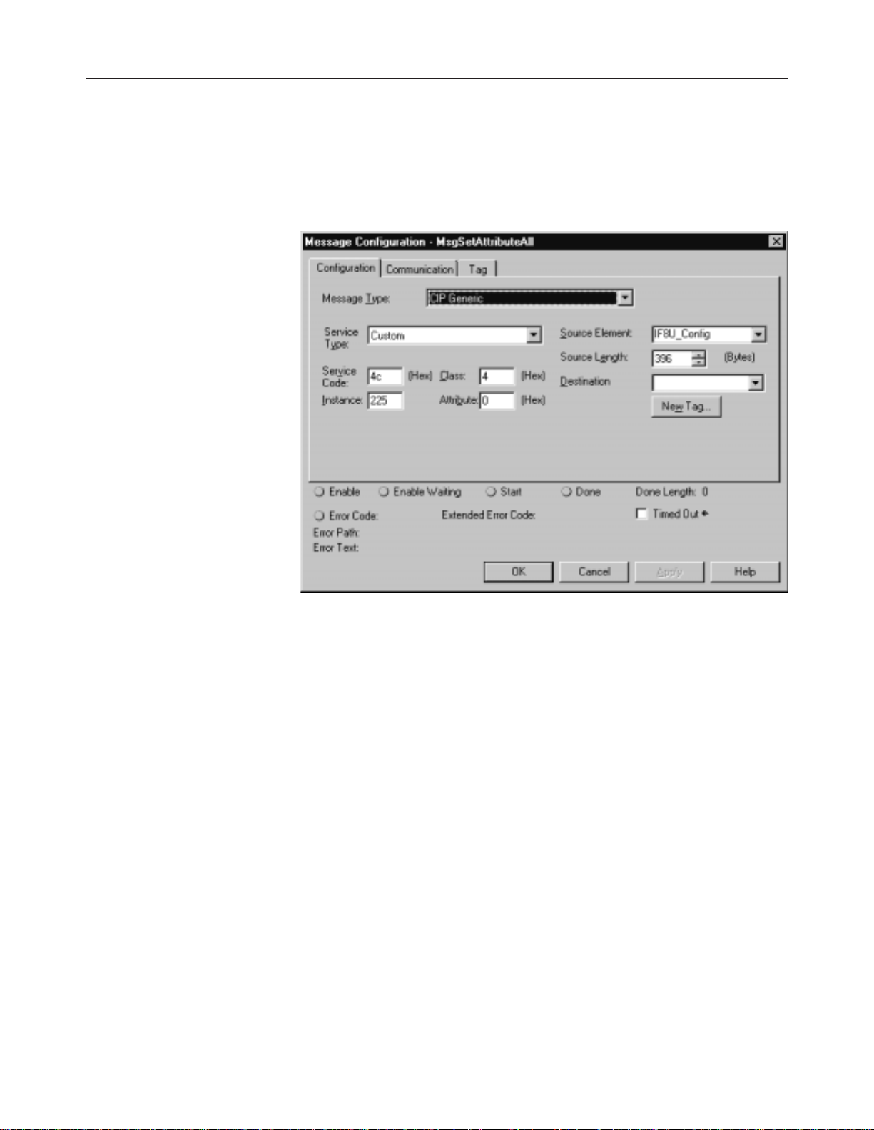
4. Perform a “Set Attribute All” or Module Reconfigure message
instruction via ladder logic. Refer to your sample program for information
about the “DoSetAttrAll” command.
Note: If an invalid configuration is sent to the module a connection error
will occur. See chapter 7 for a list of error codes.
Page 39

Chapter 5: Channel Configuration, Data, and Status 29
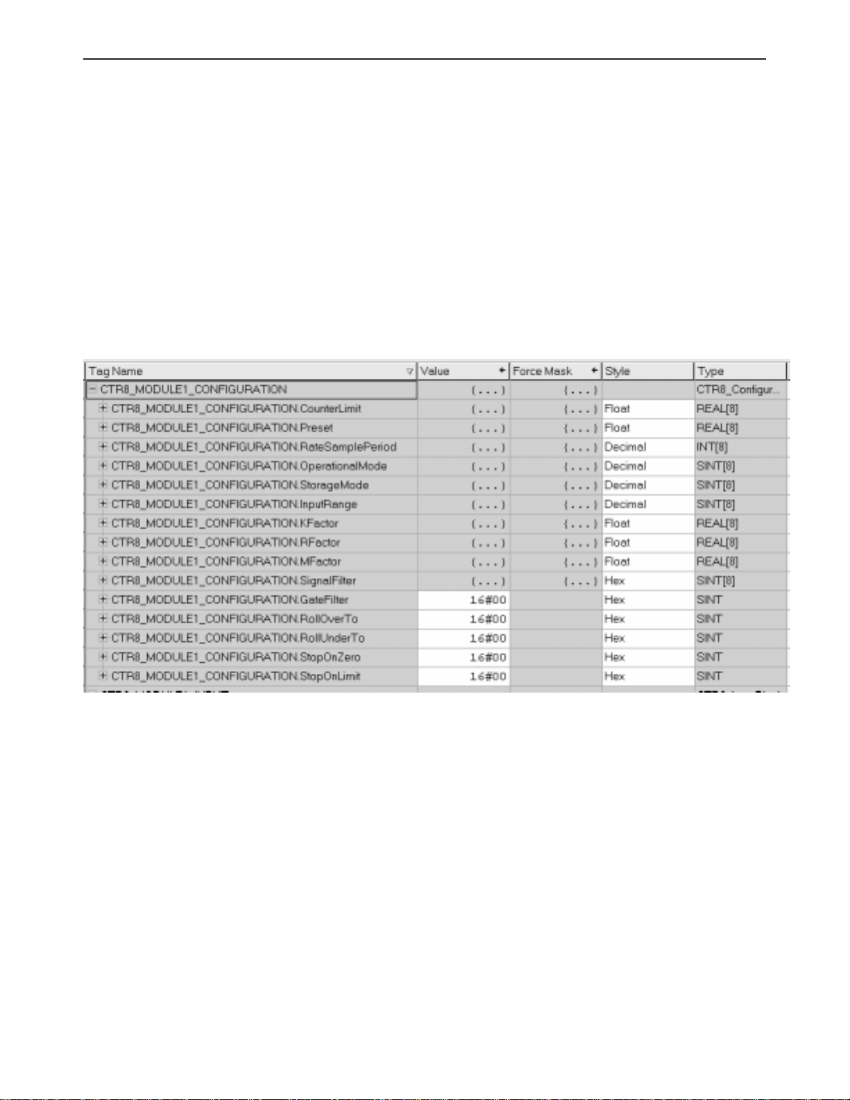
Configuration Tags
Channel Specific
Settings
The following Global Module Settings and Channel Specific Settings
sections allow custom configuration of the module. These tags can be
found within the CTR8_config controller tags.
[x] designates the channel number
(C) designates the value may be changed during module operation
CountLimit[x] 0 - 16777215 FLOAT (C)
Designates the channel rollover value. The maximum value is 1677215
when scaling is off. When scaling is applied the maximum value is
1677215/K*M.
Preset[x] 0 - 16777215 FLOAT (C)
Designates the channel preset value. Module begins counting at this value.
IMPORTANT: This value cannot be greater than the rollover value. The
maximum value is 1677215 when scaling is off. When scaling is applied the
maximum value is 1677215/K*M.
RateSamplePeriod[x] 0-2000 INT
When using period/rate mode, set this value as a multiple of 10ms between
0 and 2000. This becomes the integration time over which rate data is
averaged.
OperationalMode[x] 0,1 INT
Designates channel operational mode.
0 = unidirectional counter mode (Up)
1 = bidirectional counter mode (Up / Down)
2 = encoder X1 mode
3 = encoder X4 mode
Note: Channels must be configured in pairs. (0,1) (2,3) (3,4) (4,5) (5,6) (6,7)
Input configurations determine how the 8 inputs cause the counter to
increment or decrement. The four available configurations are:
• Uni-Directional (up)
• Bi-Directional (up and down using two channels)
• X1 Quadrature Encoder
• X4 Quadrature Encoder
Page 40

30 ControlLogix™ Counter Module
Uni-Directional
With this configuration, the input increments in an upward direction. All 8
channels may be configured in the unidirectional mode. Every clock pulse
will increment the counter on the rising edge. Note: The direction of the
counter may be inverted by setting the Count Direction bit described in the
Configuration chapter.
Bi-Directional
The bidirectional counter requires 2 input channels. In this mode one
channel is used as the counter input and the 2
determine the count direction. The counter will increment when the
Direction Channel value is 0, and will decrement when the Counter
Direction Channel value is 1.
X1 Quadrature Encoder
The quadrature mode requires 2 input channels. When a quadrature
encoder is attached to an input channel pair, A and B, the count direction is
determined by the phase angle between inputs A and B. If A leads B, the
counter increments. If B leads A, the counter decrements. (The counter
changes value only on one edge of input 1.) The counter increments once
per quadrature cycle.
nd
channel is used to
Note: The Quadrature mode provides additional Anti-Jitter circuitry.
This distinguishes between a valid quadrature sequence and an
invalid sequence due to electrical noise or jitter. Jitter can occur if a
quadrature encoder stops rotating right at an input sensor trip point.
This can cause additional unwanted clock pulses. Quadrature mode
can detect invalid transitions and filter these out.
X4 Quadrature Encoder
Like the X1 quadrature encoder, the count direction is determined by the
phase angle between inputs A and B. If A leads B, the counter increments.
If B leads A, the counter decrements. However, the counter changes
value on the rising and falling edges of inputs A and B. The counter
increments four times per quadrature cycle.
Page 41

Chapter 5: Channel Configuration, Data, and Status 31
A
Input A
A
B
x1 Count
x4 Count
B
Quadrature
Input B
Encoder
Forward Rotation Reverse Rotation
1
2
3
1 2 3 4 5 6 7 8 9 10 11 12
2
10
11 10 9 8 7 6 5 4 3 2 1 0
StorageMode[x] 0 - 4 INT (C)
This mode determines how the gate behavior effects counter behavior .
0 = no store mode
1 = store and continue mode
2 = store, wait, and resume mode
3 = store and reset, wait, and start mode
4 = store and reset, and start mode
The behaviors are characterized as follow:
StorageMode = 0 - No gate activity stored
StorageMode = 1 - Read, Store count, and continue counting
Page 42

32 ControlLogix™ Counter Module
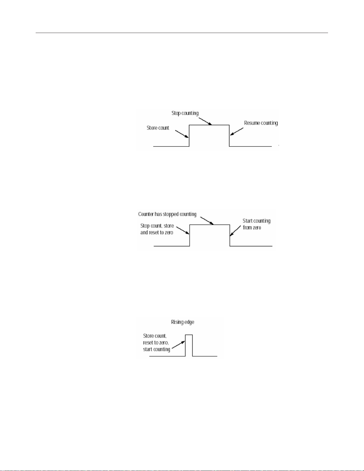
StorageMode = 2 - Store/Wait/Resume
StorageMode = 3 - Store-Reset/Wait/Start
StorageMode = 4 - Store-Reset/Start
InputRange[x] 0, 1 INT
This setting determines the threshold were the counter will begin to trigger.
Select the range that is best suited to your sensor’s range.
0= AC 50mVpp threshold
1= AC 200mVpp threshold
2= 5V
3= 12V/24V
KFactor[x] 0 - 1x10
32
FLOAT (C)
The K scale factor is used for counter scaling. This allows users to scale
the counter output into more useful units, like gallons per minute. When a
non-zero Scale Factor value is set the scale calculation is always
performed. A value of zero must be written to the Scale Factor to disable
this feature. This counter value is divided by the K factor. K factors are
positive numbers.
RFactor[x] 0 - 1x10
32
FLOAT (C)
In Program Mode the data value in this register is used for scaling. The
M scale factor is used for meter calibration. When a non-zero Scale
Factor value is set the scale calculation is always performed. A value of
zero must be written to the Scale Factor to disable this feature.
Page 43

Chapter 5: Channel Configuration, Data, and Status 33
The M factor value expressed as a floating point number. This value is
multiplied by the counter actual count value, and gives the M factor a
range of +- TBD (Prior counter modules we produced have been +/-
3.2765). Most M factors will be within +- 5% of 1.0000.
MFactor[x] 0 - 1x10
32
FLOAT (C)
The R scale factor can be used for scaling of the output frequency. The
output frequency is divided by the R scale value. The frequency value is
divided by the R factor. R factors must be positive numbers. A negative
value will cause a configuration error.
SignalFilter[x] 0-3 INT
Designates whether channel 0 uses the analog filter
0 = do not use analog or digital filter
1 = use digital filter (25kHz)
2 = use both digital (25kHz) and analog (12kHz) filters
3= use digital (25kHz), analog (12kHz), and debounce filter (30Hz)
NOTE: The digital and analog filters are separate entities which are
combined into the same tag on this module. The debounce filter
debounces the input for 35 to 40msec after the input transitions.
GateFilter[x] 0,1 INT
0 = No filter
1 = Debounce filter.
The debounce filter debounces the input for 35 to 40msec after the input
transitions.
RollOverTo[x] 0,1 BOOL (C)
Designates which value channel 0 will roll-over to:
0 = zero
1 = preset
RollUnderTo[x] 0,1 BOOL (C)
Designates which value channel 0 will roll-under to:
0 = normal (max value)
1 = preset
Stoponzero[x] 0,1 BOOL (C)
Designates what channel 0 will do when it counts down to 0.
0 = roll-under
1 = stop at zero
Stoponlimit[x] 0,1 BOOL (C)
Designates what channel 0 will do when it counts up to the count_limit.
0 = rollover
1 = stop at the limit
Page 44

34 ControlLogix™ Counter Module
Output Tags
Disable[x] 0 , 1 BOOL
Enable the counter for channel [x].
0=enable
1=disable
ResetCounter[x] 0,1 BOOL
Resets counter 0 and begins counting.
0 = do not reset
1 = reset
LoadPreset[x] 0 . 1 BOOL
Loads preset count value into counter [x] and begins counting.
0 = no action
1 = load preset
ResetFlags[x] 0 ,1 BOOL
Reset all flags.
0=not Reset
1=Reset
CounterInvert[x] 0,1 BOOL
Invert current direction of counter.
0=Standard
1=Inverted
Input Tags
ResetNewStoredFlag[x] 0,1 BOOL
Reset new stored data flag.
0=not Reset
1=Reset
ResetNewRateFlag[x] 0,1 BOOL
Reset rate data flag.
0=not Reset
1=Reset
The following data tags are preceeded by the tag name
CTR8_Input.ChannelData[x] where x is the channel number 0-7.
CommStatus 0,65535 DINT
Displays module connection status.
0 = module is connected
65535 = module is not connected
Count[x] 0-16777215 FLOAT
Displays the channel count value.
Page 45

Chapter 5: Channel Configuration, Data, and Status 35
StoredValue[x] 0-16777215 FLOAT
Displays the value of the stored stored counts register. The maximum
value is 1677215 when scaling is off. When scaling is applied the
maximum value is 1677215/K*M.
Rate[x] 0 - 65,000 REAL
Current rate value.
EnableEcho[x] 0, 1 BOOL
Software enable for the channel. This is an echo of the output tag.
0=Enable
1=Disable
WasReset[x] 0 ,1 BOOL
Displays whether the channel counter was reset.
0 = Counter was not reset
1 = Counter was reset
WasPreset[x] 0 ,1 BOOL
Displays whether the preset value for the channel counter was loaded.
0 = Preset value was not loaded
1 = Preset value was loaded
NewStoredData 0, 1 BOOL
0 = Data not stored
1 = Data Stored
NewRateData 0,1 BOOL
0 = Data is Old
1 = Data is New
GateState[x] 0,1 BOOL
Displays the channel Z state.
0 = Gate is Not Active
1 = Gate is Active
CounterInputState[x] 0,1 BOOL
This echos the state of the input. Note that this is also impacted by the
gate and/or enable line.
CountDirection[x] 0,1 BOOL
0 = Counting up
1 = Counting down
CTRLimit[x] 0,1 BOOL
This flag is latched when counts are equal to the user defined limit.
0 = Not set
1 = Set
CTRZero[x] 0,1 BOOL
0 = Not set
1 = Set
Page 46

36 ControlLogix™ Counter Module
CST DINT
Coordinated System Time. This is the time that the processor reads data
from the FPGA. It is not the actual time that the count occurred. There
will only be one CST tag for the entire module.
Page 47

Chapter 5: Channel Configuration, Data, and Status 37
Page 48

38 ControlLogix™ Counter Module
Programming Examples
Earlier chapters explained how the tag configuration defines the way the
module operates. This chapter shows some basic programming which
controls the operation of the module. It also provides you with segments
of ladder logic specific to unique situations that might apply to your
programming requirements.
Chapter 6
Initial Programming
Figure 6.1 illustrates some basic ladder logic commands which will allow
you to:
• program the initial configuration into the module
• copy data to user defined tags
• reset the module
• make on-the-fly configuration changes
• unlatch alarms
Additional ladder logic and configuration samples may also be found on
our web site: www.spectrumcontrols.com.
Page 49

Chapter 6: Ladder Program Examples 39
Figure 5.1 Sample Ladder Logic
Rung 0 - This rung copies the configuration data (CTR8_Config) into the
module’s configuration image memory . This rung is required.
Rung 1 - This rung copies the input data received from the module’s input
memory into the CTR8_Input tag for monitoring and ladder usaged. this
rung is required.
Rung 2 - This is an optional example rung indicating how to reset the
module via ladder logic.
Rung 3 - This is an optional example rung indicating how to send on-thefly configuration data to the module. This is useful if you would like to
change channel alarm or scaling tags without causing interuption in
channel updates. Changing other tags will cause a 2.5 second delay in
channel updates but the connection will not be interupted.
Page 50
40 ControlLogix™ Counter Module
Y ou may use either the SetAttributeAll to accomplish this.
Set Attribute All message:
Page 51

Using the gate
storage mode
Chapter 6: Ladder Program Examples 41
The gate storage mode allows you to configure the external gate to react
in several ways. The StorageMode[x] tag has 5 valid configurations:
StorageMode[x]
This mode determines how the gate behavior effects counter behavior .
0 = no store mode
1 = store and continue mode
2 = store, wait, and resume mode
3 = store and reset, wait, and start mode
4 = store and reset, and start mode
StorageMode = 1 - Read, Store count, and continue counting
This mode could be used in a cutting operation to determine the length of
the cut material. When the gate is triggered the current count value is
stored and the counter continues to count. The length of the material
would then be determined by subtracting the correct count value from the
stored value.
The gate behavior
Page 52
42 ControlLogix™ Counter Module
StorageMode = 2 - Store/Wait/Resume
This mode may be used in a situation were accumulated count is
important but the process may stop. For instance, if you are running filling
line and want to know the daily production a flowmeter will measure the
total quantity even through start/stop cycles.
StorageMode = 3 - Store-Reset/Wait/Start
This mode could be used in a bottle filling line when you want to control
the precise amount being dispensed. The fill occurs, the enable is
triggered and the bottle moves. The next bottle comes into place and the
fill starts at zero.
StorageMode = 4 - Store-Reset/Start
This mode could be used for a meter proving line when there are two
trigger points, a start and a stop. A pulse trigger caused by a ball crossing
a proximity switch zeros the counter and starts the accumulation. When
the ball reaches the end of the run another pulse occurs stopping and
storing the accumulated value.
Page 53

Installation
Recommendations
Chapter 6: Ladder Program Examples 43
High Impedance Inputs
If the input device is an open collector type if may be necessary to use a
pull up or pull down resistor in order to achieve the proper threshold
crossover point. W e recommend stating is a 1kohm resistor and typing it
between the input path and ground to pull down or the input path an a +12/
24V source for pull up.
Filter Frequency Settings
Use of digital filters will insure best possible performance.
Recommendations are as follows:
Maximum Signal Input Filter
65kHz No Filtering
25kHz 25kHz Digital Filter
12kHz 25kHz and 12kHz Filters
Debounce Filter
The debounce filter is best used when the gate input is connected to low
frequency input devices such as relays or proximity switches. These
devices do not typically have any on-board debounce circuitry .
Page 54

44 ControlLogix™ Counter Module
Meter Proving
The 1756sc-CTR8 module provides a feature that allows the user to
perform meter proving functions. A typical meter proving application
would include two detector sensors that are located a fixed distance from
each other within a section of pipe used specifically for meter proving.
The operation does not disrupt the in situ flowmeter’s operation.
Detector #1
Displacer
Detector #2
Utilizing the external gate enable to start and stop count functions enables
the user to count pulses as fast as 65kHz to an accuracy of 1 count.
Here is an example wave form representing the start and stop transitions
on the external gate enable, and the associated pulses that the module
would accumulate: [Storage mode 3, store, reset, wait, start]
External Channel Enable
Flow Meter Input
1 2 3 4 NA
Given the above wave form, the module will begin counting the first
positive going input pulse after the external enable input goes low . The
module will accumulate 4 counts in the channel count register and stop
when the external enable input goes high.
Page 55

Chapter 6: Ladder Program Examples 45
Page 56

Using Module
Indicators to
Troubleshoot
Chapter 7
T roubleshooting
The count module has indicators which provide indication of module
status. ControlLogix modules use the following:
LED This display: Means Take this action:
O K Steady Green Light The inputs are being multicast No ne
O K Flashing Green Light The module has passed internal None
diagnostics but is not currently
performing connected communication
O K Flashing Red Light Previously establisched communication Check controller
has timed out and chassis communications
O K Steady Red Light It is likely the module should be replaced See below
Under fault conditions the CTR8 will communicate a particular error via a
LED blink code. A description of the fault conditions and LED blink codes
is listed below ...
OK LED SYS LED Fault Status
RE D 1 Blink EEPROM seed completed.
RE D 2 Blinks– EEPROM seed failed.
RE D 3 Blinks EEPROM CRC failed.
RE D 4 Blinks Invalid serial number .
RE D 5 Blinks Boot code CRC failed.
RE D 6 Blinks App CRC failed.
RE D 7 Blinks– FPGA configuration fail.
RE D 8 Blinks– FPGA scan fail.
RE D 9 Blinks Not Applicable
RE D 10 Blinks XA W atchdog timeout.
In most instances you may try resetting the module to clear the fault. If you are not successful, contact technical
support as the module may require repair.
Note: In RSLogix5000 the Fault Status can be seen in the “Module Info”
tab of the module’s properties dialog.
Page 57
Using RSLogix 5000
to Troubleshoot
Your Module
Chapter 7: Testing Y our Module 47
The following LED display is used with ControlLogix analog input
modules:
In addition to the LED display on the module, RSLogix 5000 will alert you
to fault conditions. You will be alerted in one of three ways:
· W arning signal on the main screen next to the module-This occurs when
the connection to the module is broken
· Fault message in a screen’s status line · Notification in the Tag Editor General module faults are also reported in the T ag Editor . Diagnostic faults
are only reported in the T ag Editor
· Status on the Module Info Page
The screens below display fault notification in RSLogix 5000.
Page 58

48 ControlLogix™ Counter Module
Module
Configuration Errors
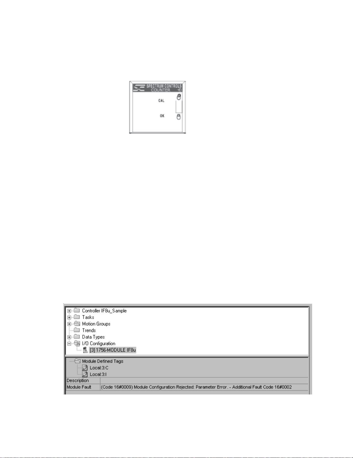
Fault information on the properties screen.
Determining Fault Type
When you are monitoring a module’s properties dialog in RSLogix 5000
and receive a fault message, the module fault area lists the type of fault.
The “Additional Fault Code” value details the configuration error if the
“(16#0009) module configuration rejected: Parameter Error” was
received.
Global Err ors
16#0F04 - .ConfigurationRevError
If the .ConfigurationRevNumber tag is 1 and a second owner
attempts to connect with a different configuration, this error
will occur. You must adjust the second owners configuration
to match the first.
16#0F05 - .ConfiguratinRevNumber Error
An invalid value has been entered into this tag.
Page 59

Chapter 7: Testing Y our Module 49
Channel Specific Err ors
Note: n = channel number (0-7)
0x010(n) Preset is defined larger than rollover limit for channel (n).
0x0200 Input Range mismatch for channel pair 0 and 1.
0x0202 Input Range mismatch for channel pair 2 and 3.
0x0204 Input Range mismatch for channel pair 4 and 5.
0x0206 Input Range mismatch for channel pair 5 and 7.
0x030(n) Invalid operational mode for channel (n).
0x040(n) Invalid storage mode for channel (n).
0x050(n) Invalid input range for channel (n).
0x060(n) Invalid signal filter for channel (n).
0x070(n) RateSamplePeriod out of range for channel (n).
0x0800 Operational mode mismatch for channel pair 0 and 1.
0x0802 Operational mode mismatch for channel pair 2 and 3.
0x0804 Operational mode mismatch for channel pair 4 and 5.
0x0806 Operational mode mismatch for channel pair 6 and 7.
0x090(n) Preset too high for channel (n).
0x0A0(n) Count limit too high for channel (n).
0x0B0(n) RateSamplePeriod not divisible by 10 for channel (n).
Note: If there are multiple errors in the configuration tags only one will be
displayed at a time. Once the displayed error has been corrected, the
additional errors will be displayed upon reconnection to the module. Each
error must be resolved before a running connection will be allowed.
Page 60

50 ControlLogix™ Counter Module
Maintaining Y our Module
And Ensuring Safety
Read this chapter to familiarize yourself with:
• preventive maintenance
• safety considerations
The National Fire Protection Association (NFPA) recommends
maintenance procedures for electrical equipment. Refer to article 70B of
the NFPA for general safety-related work practices.
Preventive
Maintenance
The printed circuit boards of your module must be protected from dirt, oil,
moisture, and other airborne contaminants. T o protect these boards, install
the ControlLogix system in an enclosure suitable for its operating
environment. Keep the interior of the enclosure clean, and whenever
possible, keep the enclosure door closed.
Chapter 8
Safety
Considerations
Also, regularly inspect the terminal connections for tightness. Loose
connections may cause a malfunctioning of the SLC system or damage to
the components.
WARNING
!
Safety is always the most important consideration. Actively think about the
safety of yourself and others, as well as the condition of your equipment.
The following are some things to consider:
Indicator Lights – When the module status LED on your module is
illuminated, your module is receiving power.
POSSIBLE LOOSE CONNECTIONS
Before inspecting connections, always ensure that
incoming power is OFF.
Failure to observe this precaution can cause personal injury and equipment
damage.
Activating Devices When Troubleshooting – Never reach into a
machine to activate a device; the machine may move unexpectedly. Use a
wooden stick.
Page 61

Chapter 8: Maintaining Y our Module And Ensuring Safety 51
Standing Clear Of Machinery – When troubleshooting a problem with
any ControlLogix system, have all personnel remain clear of machinery .
The problem may be intermittent, and the machine may move
unexpectedly. Have someone ready to operate an emergency stop switch.
CAUTION
!
Safety Circuits – Circuits installed on machinery for safety reasons (like
over-travel limit switches, stop push-buttons, and interlocks) should always
be hard-wired to the master control relay . These circuits should also be
wired in series so that when any one circuit opens, the master control
relay is de-energized, thereby removing power . Never modify these
circuits to defeat their function. Serious injury or equipment damage may
result.
!
POSSIBLE EQUIPMENT OPERATION
Never reach into a machine to actuate a switch.
Also, remove all electrical power at the main power
disconnect switches before checking electrical
connections or inputs/outputs causing machine
motion.
Failure to observe these precautions can cause personal injury or equipment
damage.
WARNING
EXPLOSION HAZARD
SUBSTITUTION OF COMPONENTS MA Y IMP AIR
SUITABILITY FOR CLASSI DIVISION2.
WARNING
!
EXPLOSION HAZARD
DO NOT DISCONNECT EQUIPMENT UNLESS POWER
HAS BEEN SWITCHED OFF OR THE AREA IS KNOWN
TO BE NON-HAZARDOUS
NONO
TE:TE:
NO
TE: THIS EQUIPMENT IS SUITABLE FOR USE IN
NONO
TE:TE:
CLASS
NON-HAZARDOUS LOCA TIONS ONL Y.
II
I, DIVISION 2, GROUPS A, B, C, AND D OR
II
Page 62

52 ControlLogix™ Counter Module
WARNING
EXPLOSION HAZARD
!
!
WHEN IN HAZARDOUS LOCATIONS, TURN OFF
POWER BEFORE REPLACING OR WIRING MODULES.
WARNING
THIS DEVICE IS INTENDED TO ONL Y BE USED WITH
!
THE ALLEN-BRADLEY CONTROLLOGIX 1756 I/O
SYSTEM.
Page 63

Chapter 8: Maintaining Y our Module And Ensuring Safety 53
Page 64

Electrical
Specifications
Appendix A
Module Specifications
This appendix lists the specifications for the 1756sc-CTR8 Counter
Module.
Backplane Current Consumption 230 mA at 5 VDC
75 mA at 24 VDC
Backplane Power Consumption 3.00W maximum (0.6W @ 5 VDC, 2.4W @ 24 VDC)
Maximum Power Dissipation 4.8W (All inputs at maximum voltage)
Number of Channels 8 unidirectional / 4 bi-directional and quadrature
Number of Gates 8 gate inputs
I/O Chassis Location Any I/O module slot
Conversion Method FPGA
Input Filtering Three user sel ectable filters (12kHz, 25kHz, debounce)
Calibration Module does not require calibration
Input Overvoltage Protection +-50VDC cont. 50V ACrms
Input Overcurrent Protection < 4ma @ 50VDC
Isolation 2550 VDC continuous between inputs and chassis
ground and between inputs and backplane.
Physical Specifications
LED Indicators 1 red/green status indicators, 1 red system status
Recommended Cable: Shielded twisted pair extension wire
Belden 8761 or equivalent
shielded Belden #9501
Maximum Wire Size One 16 A WG wire or two 22 AWG wires per terminal
Page 65

Environmental
Specifications
Input Specifications
Appendix A: Module Specifications 55
Operating T emperature 0°C to 60°C (32°F to 140°F)
Storage T emperature -40°C to 85°C (-40°F to 185°F)
Relative Humidity 5% to 95% (without condensation)
Certification CE, UL & CUL approved
Hazardous Environment Class1 Division 2 Hazardous Environment
Classification Groups A, B, C, D
UL 508
73/23/ EEC Low V oltage Directive
89/336/ EEC Electromagnetic Compatibility
CSA (Class 1, Div 2, Group A,B,C,D)
CE compliance to EN 61010-1 and EN 61131-2, EN61000-6-2:2001, EN61000-6-4:2001
EN61010-1:2001, EN61131-2:1994 + A11:1996 + A12:2000
FM (Class 1, Div 2, Group A,B,C,D)
Voltage Range AC 50mVpp AC 200mVpp 5VDC 12/24VDC
VIL -50mV -200mV 1V 6
VIH +50mV +200mV 3.5V 10.5
Vmax CE +-50VACrms +-50VACrms +-50VDC +-50VDC
Current Range 4ma Max @ 50VDC
Input impedance
Resistance V oltage dependent >1Mohm at 5V , 24k typ at 24V.
Capacitance 600pF typical
Counter Speed 0 to 65KHz
Input Frequency 0 to 65kHz
Counter Gate Input
VIL 1.0V min
VIH 3.5V max
Vmax 30V
Min/Max Duty Cycle
Input Range MaxFrequency Min Duty Cycle Max Duty Cycle Min Pulse Width
AC (50mV) 65kHz NA NA N A
AC (200mV) 65kHz N A NA NA
5VDC 65kHz 30 60 4.6usec
12VDC 65kHz 35 70 5.4usec
24VDC 65kHz 25 55 3.8usec
Channel Update Time
With scaling 13ms for all 8 channels.
Page 66
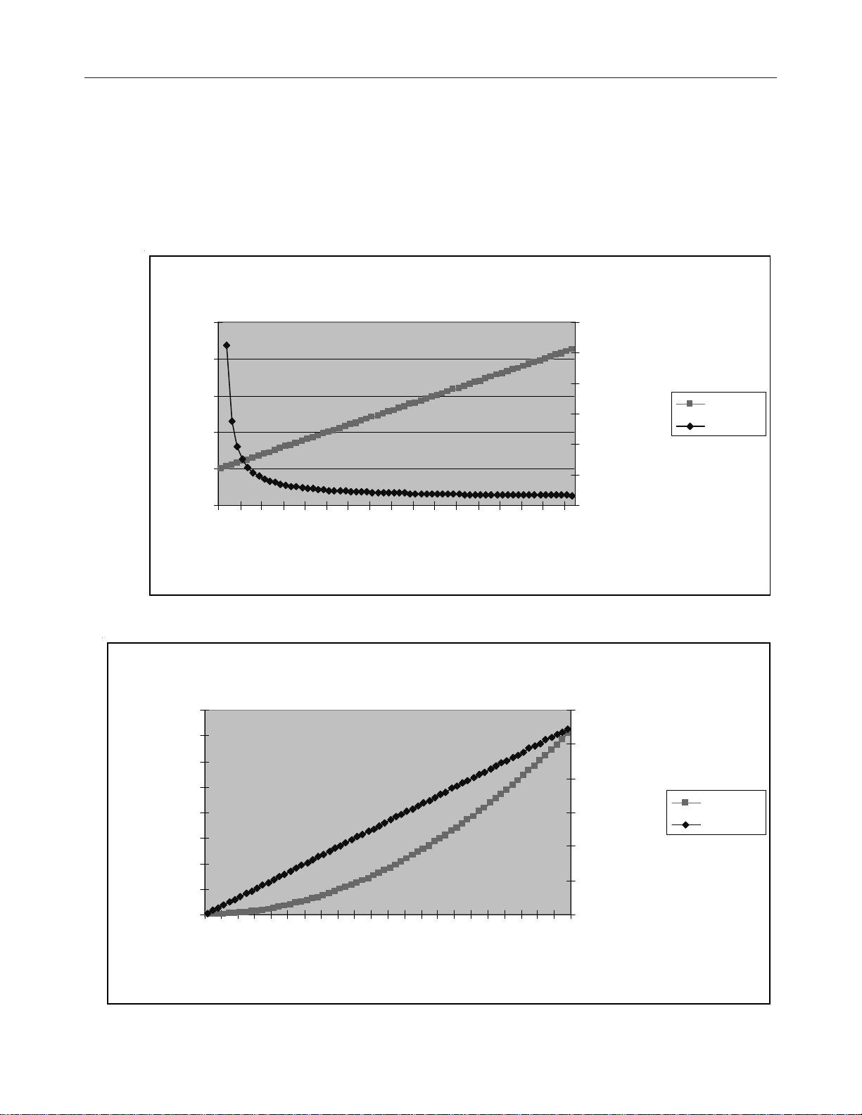
56 ControlLogix™ Counter Module
)
)
AccuracyAccuracy
Accuracy
AccuracyAccuracy
Error (Hz)
2.5
1.5
0.5
Fr
Frequency Mode 1Hz Accuracy 65kHz Accuracy
max typ max
Instant* +/-0.00Hz +/-354Hz +/-354Hz
Average +/-0.5Hz +/-1Hz +/-2Hz
Av era ge Mode Fr equency Err or
0.060%
0
0.050%
0.040%
0.030%
0.020%
0.010%
0.000%
Error(%
Error(Hz)
Error(%)
2
1
0
eq
3
000
7
00
0
11000
700
0
310
0
00
0
50
9
3
3
Freq(Hz)
000
4
30
00
47000
51000
0
19000
0
0
3
2
2
000
5
1
55
0
0
0
59000
6
300
Inst antaneous Mode Frequency Err or
400.000
350.000
300.000
250.000
200.000
150.000
Error (Hz )
100.000
50.000
0.000
F
r
eq
2000
5000800011000
1400017
000
200002
3000
26
0
0
00
0
0
900032
5000
2
3
Frequency
3800041000
44
0
0
0
47000
0000
5
300056
5
0
00
5900062
0
Maximum Count V alue 16,777,215
0.600%
0.500%
0.400%
0.300%
0.200%
0.100%
0.000%
0
0
Error (%
Err or (Hz)
Err or (%)
Page 67

Appendix A: Module Specifications 57
Page 68

Appendix B
Programming Y our Module
This chapter explains how program your module in the ControlLogix
system. It also describes how to the module’ s input configuration are
incorporated into your ladder logic program. T opics discussed include:
• importing the module’s configuration profile
• reviewing accessing and altering configuration options.
• configuring the modules input type and filter settings
• configuring alarms and limits
Module Installation
Adding Your Module
to a Project
Incorporating your module into the system is similar to adding any type of
I/O module. You will use your RSLogix 5000 programming software.
The module is not currently in the pick list of this software so you will use
the Generic 1756 Module option as your starting point. This feature allows
you to inport the configuration database into your project and use ladder
logic to set the attributes of each tag. These settings control features such
as the modules input type, channel input range, data format, filter
frequency, etc.
Y ou will need to download the sample project from our website and then
import this into your program. Then you may access the controller tags to
configure the module. Ladder logic samples are also provided with this
sample project.
The module has a unique set of tag definitions which are used to configure
specific features. Chapter 5, Channel Configuration, Data, and Status,
gives you detailed information about the data content of the configuration.
These values are set using your programming software and ladder logic.
Before you can use these feature you must first include the module into
the project.
Page 69

Appendix B: Installing the module using a Generic Module profile 59
1. Open your project and go to the “Add I/O module” menu under
controller configuration.
2. You will now see the list of all I/O modules. Select the “Generic 1756
I/O” option.
3. After clicking “OK” you are presented with the following dialog for
setting up the general information about the module. Use the same values
specified here:
Page 70
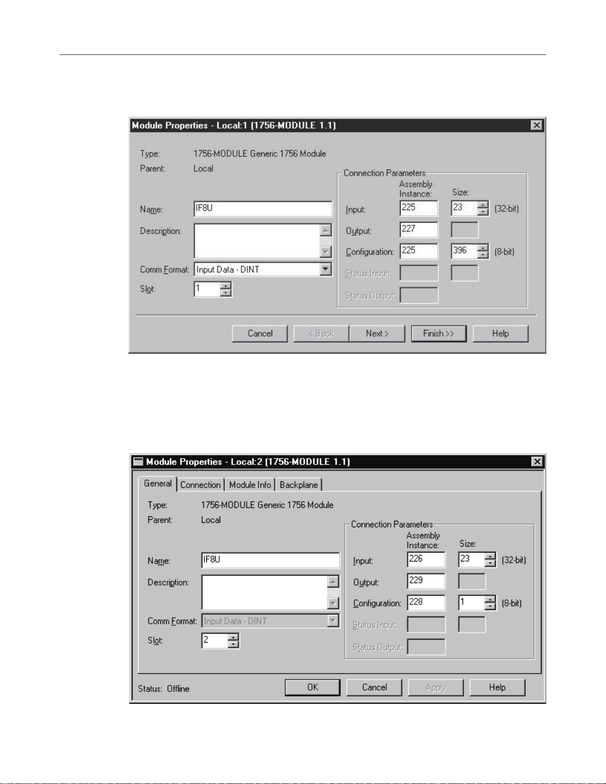
60 ControlLogix™ Counter Module
Owner Controller Connection (Controller provides configuration)
Listen-only controller connection. (Controller does not provide
configruration but monitors input data only . Another owner controller must
exist.)
Page 71

Appendix B: Installing the module using a Generic Module profile 61
4. Specify an RPI interval between 10.0 and 750.0 ms:
Page 72

62 ControlLogix™ Counter Module
Page 73

Getting Technical
Assistance
If you need technical assistance, please review the information in
Chapter 6, “Testing Your Module,” before calling your local distributor
of Spectrum Controls.
Note that your module contains electronic components which are
susceptible to damage from electrostatic discharge (ESD). An
electrostatic charge can accumulate on the surface of ordinary plastic
wrapping or cushioning material. In the unlikely event that the
module should need to be returned to Spectrum Controls, please
ensure that the unit is enclosed in approved ESD packaging (such as
static-shielding / metallized bag or black conductive container).
Spectrum Controls reserves the right to void the warranty on any unit
that is improperly packaged for shipment.
For further information or assistance, please contact your local
distributor, or call the Spectrum Controls technical Support at :
USA - 440-646-6900
United Kingdom - 01908 635230
Australia - 800-809-929 or (61) 398-990-335
Brazil - (55) 11 3618 8800
Europe - (49) 2104 960 333
Declaration of
Conformity
Declaration available upon request.
Page 74

©2003 Spectrum Controls, Inc. All rights reserved. Specifications subject to change without notice.
The Encompass logo and ControlLogix are trademarks of Rockwell Automation.
Publication 0300199-01 Rev. B December 2003. Printed in U.S.A.
Corporate Headquarters
Spectrum Controls Inc.
P .O. Box 5533
Bellevue, WA 98006 USA
Fax: 425-641-9473
Tel: 425-746-9481
W eb Site: www.spectrumcontrols.com
E-mail: spectrum@spectrumcontrols.com
 Loading...