

Page 1

Publication 0300146-08 Rev. J
Isolated-Circuit Discrete Input and Output Modules
(Cat. No. 1746sc Series)
Installation Instructions
Input Module Catalog Numbers:
1746sc-IA8I Isolated-Circuit 100/120 V ac/dc Inputs (8)
1746sc-IB8I Isolated-Circuit 24 Vdc Inputs (8)
1746sc-IC8I Isolated-Circuit 48 Vdc Inputs (8)
1746sc-IM8I Isolated-Circuit 200/240 V ac/dc Inputs (8)
Output Module Catalog Numbers:
1746sc-OAP8IIsolated-Circuit 120/240 Vac Outputs (8)
Page 2

Page 3

Installation Instructions
Isolated-Circuit
Discrete Input and Output Modules
Preface
In addition to providing module specifications, this document tells you how
to:
™
• install your module into the SLC 500
• wire field devices to your module
• interpret your module’s LED indicators
• check for blown fuses (1746sc-OAP8I only)
• get technical assistance
Please read all the information in this publication before installing these
products. This publication assumes a full working knowledge of the relevant
programmable controller.
chassis
1
1
Page 4

Installation Instructions
Installation Instructions
Isolated-Circuit
Isolated-Circuit
Discrete Input and Output Modules
Discrete Input and Output Modules
2
2
Page 5

Installation Instructions
Isolated-Circuit
Discrete Input and Output Modules
Table Of Contents
General Information And Specifications .........................................................4
General Specifications..........................................................................................4
-IA8I Specifications, On/Off-State Voltage Range, & Circuit Diagram .............. 6
-IB8I Specifications, On/Off-State Voltage Range, & Circuit Diagram .............. 7
-IC8I Specifications, On/Off-State Voltage Range, & Circuit Diagram .............. 8
-IM8I Specifications, On/Off-State Voltage Range, & Circuit Diagram ............. 9
-OAP8I Specifications, Operating Voltage Range, & Circuit Diagram ............. 10
Important Pre-Installation Considerations.....................................................11
™
Installing Your Module Into The SLC 500
Wiring Field Devices To Your Module..........................................................14
CE Compliance Requirements ........................................................................... 15
-IA8I Wiring Diagram ........................................................................................ 17
-IB8I Wiring Diagram ........................................................................................18
-IC8I Wiring Diagram ........................................................................................19
-IM8I Wiring Diagram ....................................................................................... 20
-OAP8I Wiring Diagram ....................................................................................21
Chassis ....................................12
Interpreting Your Module’s LED Indicators..................................................21
Checking For Blown Fuses (1746sc-OAP8I only)........................................22
Getting T echnical Assistance.........................................................................23
3
Page 6

Installation Instructions
Isolated-Circuit
Discrete Input and Output Modules
General Information And Specifications
This module is designed exclusively to mount Allen-Bradley 1746 I/O racks
for use with Allen-Bradley SLC500 fixed and modular systems. The 1746sc-
IA8I, IB8I, -IC8I, and -IM8I feature 8 isolated-circuit inputs, each with its
own common. These modules also feature broad operating ranges for increased versatility. They are designed for use with a wide variety of input
devices, such as limit switches, float switches, selector switches, pushbuttons, and proximity switches (photo-sensors). They can even monitor
relay or motor starter outputs directly.
The 1746sc-OAP8I provides 8, triac-controlled, isolated-circuit outputs,
each with its own common. The module also provides a broad operating
range for increased versatility. It is designed for use with high inductive
loads, such as solenoids, relays, and motor starters. Unlike relay outputs,
triac outputs do not require back-EMF surge suppression for many inductive
loads. A triac output module is also a good replacement for a relay output
module when solid-state speed and reliability are desired.
General Specifications-- 1746sc Series
Isolation Voltage 1500 Vac point-to-point
1500 Vac field wiring-to-backplane
Environmental Conditions
Operational Temperature 0° to 60°C (32° to 140°F)
Storage Temperature -40° to +85°C ( -40° to 185°F)
Relative Humidity 5 to 95% (non-condensing)
Certifications UL/C-UL (Class I, Div 2, Groups ABCD)
Conductors Wire Size 14 gage stranded maximum
Category 1
Field Wiring Terminal Block Red, removable (A-B part 1746-RT25R)
➀
Use this conductor-category information for planning conductor routing as described in Allen-Bradley’s
system-level
Installation and Operation Manual
CE per Council Directives 89/336/EEC for EMC
and 73/23/EEC for Low Voltage
3/64 inch insulation maximum
.
➀
4
Page 7

Installation Instructions
Isolated-Circuit
Discrete Input and Output Modules
As noted in the previous table, these 1746sc-Series modules provide 1500 V
point-to-point isolation. This point-to-point isolation means:
• shorts, overloads, or noise on one circuit won’t affect devices on other
circuits.
• different power sources can be connected to the same module without
damaging components due to excessive voltage differences between points.
• interposing relays aren’t needed to achieve these benefits, saving space and
simplifying installation.
The 1746sc-OAP8I provides some additional benefits:
• each output circuit is individually fuse protected.
• blown fuses are indicated to the user through an LED and to the logic
controller through the logic controller’s input image table. This allows for
fuse monitoring and smart power-down sequencing of equipment after a
circuit failure.
For more information on the benefits of isolated circuits and other features of
the 1746sc-Series modules, call your local distributor or Spectrum Controls
(425-746-9481).
5
Page 8
Installation Instructions
Isolated-Circuit
Discrete Input and Output Modules
1746sc-IA8I Specifications
Number of Inputs 8
Points per Common 1 (individually isolated)
Voltage Category 100/120 Vac @ 50/60 Hz
100/120 Vdc, sink or source
Operating Voltage 80 to 150 Vac @ 47 to 63 Hz
85 to 170 Vdc
Nominal Input Current 16 mA @ 120 Vac, 60 Hz
Input Inrush Current (maximum) 0.7 A @ 120 Vac
Input Signal Delay (maximum)
Off to On 17 ms @ 120 Vac
On to Off 45 ms @ 120 Vac
Off-State Current (maximum) 4 mA @ 20 Vac
Power Dissipation (maximum)
Watts per point
Total watts
➁
➂
0.5 W @ 120 Vac/dc; 0.75 W @ 150 Vac/dc
4 W @ 120 Vac/dc; 6 W @ 150 Vac/dc
Backplane CurrentDraw (max.) 5 V 0.110 A
24 V 0.0 A
➀
Maximum allowable leakage current from an input device in an off state.
➁
Maximum with 1 input turned on.
➂
Maximum with all 8 inputs turned on (100% duty cycle).
2.5 mA @ 120 Vdc
7 ms @ 120 Vdc
40 ms @ 120 Vdc
➀
0.5 mA @ 20 Vdc
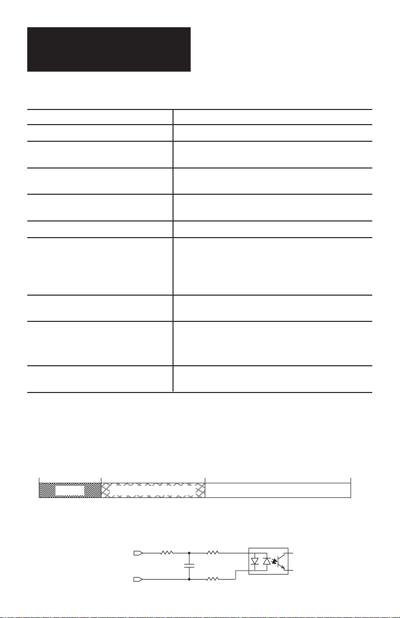
1746sc-IA8I On/Off-State Voltage Range
0 Vac*
0 Vdc
Off-State Input State Not Guaranteed On-State
* Frequency = 47 to 63 Hz
30 Vac*
20 Vdc
80 Vac*
85 Vdc
1746sc-IA8I Circuit Diagram (one circuit shown)
VAC/VDC +
IN –
249 Ω
24.3 kΩ
0.33 µF
24.3 kΩ
6
150 Vac*
170 Vdc
Page 9
Installation Instructions
Isolated-Circuit
Discrete Input and Output Modules
1746sc-IB8I Specifications
Number of Inputs 8, sink or source
Points per Common 1 (individually isolated)
Voltage Category 24 Vdc
Operating Voltage ±11.5 to 32 Vdc
Nominal Input Current 12 mA @ 24 Vdc
Input Signal Delay (maximum)
Off-State Current (maximum) 1.8 mA @ 4.5 Vac
Power Dissipation (maximum) 6.6 W @ 240 Vac/dc
Backplane CurrentDraw (max.) 5 V 0.110 A
➀
Maximum allowable leakage current from an input device in an off state.
➁
Maximum with 1input turned on.
➂
Maximum with all 8 inputs turned on (100% duty cycle).
Off to On 0.5 ms @ 24 Vac
On to Off 1 ms @ 24 Vac
Watts per point
Total Watts
➂
➁
0.4 W @ 24 Vdc; 0.6 W @ 32 Vdc
3 W @ 24 Vdc; 4.8 W @ 32 Vdc
24 V 0.0 A
➀
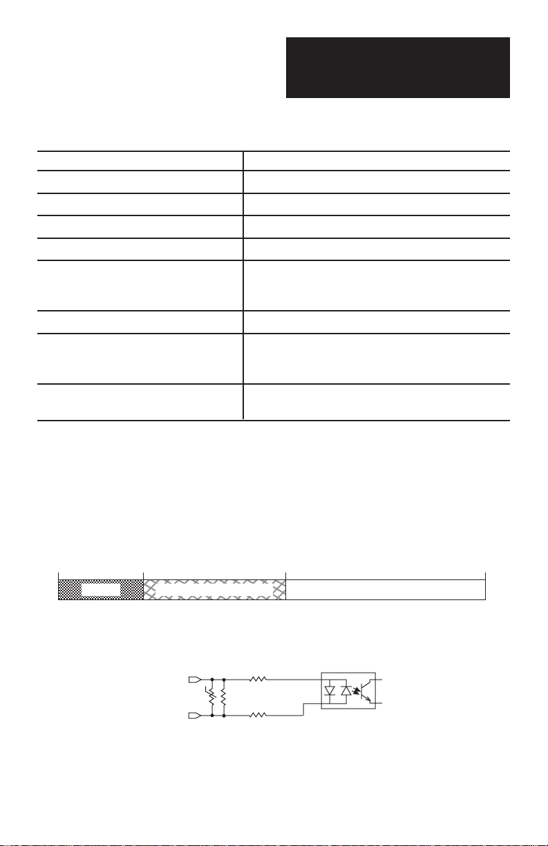
1746sc-IB8I On-Off-State Voltage Range
0 Vdc 4.5 Vdc 11.5 Vdc 32 Vdc
Off-State Input State Not Guaranteed On-State
1746sc-IB8I Circuit Diagram (one circuit shown)
VDC +
IN –
1.91 Ω
3.16 kΩ
1.91 kΩ
7
Page 10

Installation Instructions
Isolated-Circuit
Discrete Input and Output Modules
1746sc-IC8I Specifications
Number of Inputs 8, sink or source
Points per Common 1 (individually isolated)
Voltage Category 48 Vdc
Operating Voltage ± 30 to 60 Vdc
Nominal Input Current 10 mA @ 48 Vdc
Input Signal Delay (maximum)
Off-State Current (maximum) 1.8 mA @ 9.5 Vac
Power Dissipation (maximum) 4 W @ 120 Vac/dc
Backplane CurrentDraw (max.) 5 V 0.110 A
➀
Maximum allowable leakage current from an input device in an off state.
➁
Maximum with 1 input turned on.
➂
Maximum with all 8 inputs turned on (100% duty cycle).
Off to On 0.5 ms @ 48 Vdc
On to Off 1 ms @ 48 Vdc
Watts per point
Total watts
➂
➁
0.6 W @ 48 Vdc; 0.85 W @ 60 Vdc
4.5 W @ 48 Vdc; 6.7 W @ 60 Vdc
24 V 0.0 A
➀
1746sc-IC8I On/Off-State Voltage Range
0 Vdc 9.5 Vdc 30 Vdc 60 Vdc
Off-State Input State Not Guaranteed On-State
1746sc-IC8I Circuit Diagram (one circuit shown)
VDC +
IN –
7.87 Ω
6.65 kΩ
7.87 kΩ
8
Page 11

Installation Instructions
Isolated-Circuit
Discrete Input and Output Modules
1746sc-IM8I Specifications
Number of Inputs 8, sink or source
Points per Common 1 (individually isolated)
Voltage Category 200/240 Vac @ 50/60 Hz
200/240 Vdc
Operating Voltage 160 to 264 Vac @ 47 to 63 Hz
170 to 265 Vdc
Nominal Input Current 13.5 mA @ 240 Vac, 60 Hz
Input Inrush Current (maximum) 0.7 A @ 240 Vac
Input Signal Delay (maximum)
Off to On 15 ms @ 240 Vac
On to Off 40 ms @ 240 Vac
Off-State Current (maximum) 2.5 mA @ 40 Vac
Power Dissipation (maximum)
Watts per point
Total watts
➁
➂
085 W @ 240 c/dc; 1 W @ 264 Vac/dc
6.6 W @ 240 Vac/dc; 8 @ 264 Vac/dc
Backplane CurrentDraw (max.) 5 V 0.110 A
24 V 0.0 A
➀
Maximum allowable leakage current from an input device in an off state.
➁
Maximum with 1 input turned on.
➂
Maximum with all 8 inputs turned on (100% duty cycle).
2.5 mA @ 250 Vdc
7 ms @ 250 Vdc
36 ms @ 250 Vdc
➀
0.85 mA @ 40 Vdc
1746sc-IM8I On-Off-State Voltage Range
0 Vac*
0 Vdc
Off-State Input State Not Guaranteed On-State
* Frequency = 47 to 63 Hz ** 276 Vdc short-term overload (1 hour)
60 Vac*
40 Vdc
160 Vac*
170 Vdc
264 Vac*
265 Vdc**
1746sc-IM8I Circuit Diagram (one circuit shown)
VAC/VDC +
IN –
499 Ω
49.9 kΩ
0.15 µF
49.9 kΩ
9
Page 12
Installation Instructions
Isolated-Circuit
Discrete Input and Output Modules
1746sc-OAP8I Specifications
Number of Outputs 8 triac
Points per Common 1
Module Location 1746 I/O chassis
Voltage Category 120/240 Vac @ 50/60 Hz
Operating Voltage 74 to 276 Vac @ 47 to 63 Hz
Output Current Rating Per Point 1.5 A @ 30°C; 1 A @ 60°C
Output Current Rating Per Module 9 A @ 30°C; 4 A @ 60°C
Surge Current (maximum) 25 A per output for 100 ms, repeatable every 1 sec
25 A per module for 100 ms, repeatable every 1 sec
Load Current (minimum) 5 mA per output
On-State Voltage Drop (maximum) 1.0 V @ 1.5 A
Off-State Leakage Current (max.) 1 mA
Signal Delay
Off to On Zero crossing: 8.3 ms @ 60 Hz; 10.0 ms @ 50 Hz
On to Off Zero crossing: 8.3 ms @ 60 Hz; 10.0 ms @ 50 Hz
Power Dissipation (maximum) 9.85 W
Backplane CurrentDraw (max.) 5 V 0.170 A
24 V 0.0 A
➀
Maximum with the module dissipating 9 A (100% duty cycle).
➀
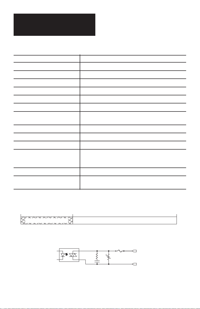
1746sc-OAP8I Operating Voltage Range
0 Vac* 276 Vac*
Operation Not Guaranteed Recommended Operating Range
* Frequency = 47 to 63 Hz
74 Vac*
1746sc-OAP8I Circuit Diagram (one circuit shown)
VAC
39 Ω
.01 µF
OUT
10
Page 13

Installation Instructions
Isolated-Circuit
Discrete Input and Output Modules
Important Pre-Installation Considerations
This module is shipped in a static-shielded container to guard against electrostatic discharge damage. Observe the following precautions when handling
the module:
CAUTION
!
ELECTROSTATICALLY SENSITIVE COMPONENTS
Observe the following precautions to guard against electrostatic damage:
• Wear an approved wrist strap grounding device, or touch a grounded
object to discharge yourself before handling the module.
• Do not touch the gold backplane connector or connector pins.
• If available, use a static-free work station.
• When not in use, keep the module in a static-shielded bag.
Failure to observe these precautions can damage your module.
When using Allen-Bradley Programming Software (APS) to configure a
chassis slot for your module, simply select your module from the list of
modules on the system I/O configuration display. (Note: Some versions of
APS list the modules without the “sc” designation, as in 1746-IA8I.) If your
module is not listed, select OTHER at the bottom of the list and enter your
module’s ID code at the prompt:
Module ID Code
1746sc-IA8I 303 1746sc-IM8I 304
1746sc-IB8I/-IC8I 324 1746sc-OAP8I 1905
11
Page 14

Installation Instructions
Isolated-Circuit
Discrete Input and Output Modules
Installing Your Module Into The SLC 500 Chassis
WARNING
!
EXPLOSION HAZARD
When in hazardous locations, turn off power before replacing or wiring
modules.
Failure to observe this precaution can cause equipment damage, severe personal
injury, or death.
WARNING
!
POSSIBLE EQUIPMENT OPERATION AND DAMAGE
Always remove power from the I/0 chassis backplane and terminal block
before removing or installing an I/O module.
• Failure to remove power from the backplane or terminal block can cause
module damage, degraded performance, or injury.
• Failure to remove power from the backplane can also cause injury or equipment damage due to possible equipment operation.
This equipment is suitable for use in Class I, Division 2, Groups A, B, C,
and D, or non-hazardous locations only.
Before installing your module into the SLC500 chassis, make sure that
nothing will block the ventillation above and below your module. Also, at
high ambient temperatures, you may need to install forced air cooling to
prevent excessive heat buildup.
To install your module into the chassis, follow these steps:
12
Page 15

Installation Instructions
Isolated-Circuit
Discrete Input and Output Modules
1.Turn off power to the I/O chassis.
2.Align the circuit board of your module
with the card guides at the top and
bottom of the chassis
3.Slide your module into the chassis until
both top and bottom retaining clips are
secure. Apply firm even pressure on
your module to attach it to its
backplane connector. Never force your
module into the slot.
Cover all unused slots with the Card Slot Filler, Allen-Bradley part 1746-N2.
To remove your module, follow these steps:
1. Turn off power to the I/O chassis.
2. Remove the terminal block or field device wiring if necessary.
3. Press the retaining clips at the top and bottom of your module.
Note that the components on the circuit board may get very hot:
• 1746sc-IB8I & -IC8I 120° C (UL temperature code T4A)
• 1746sc-IM8I 135° C (UL temperature code T4)
• 1746sc-OAP8I 100° C (UL temperature code T5)
CAUTION
HOT COMPONENTS
!
When removing the 1746sc-IM8I or -OAP8I after use, avoid touching any of
the components on its printed circuit board.
Failure to observe this precaution can cause personal injury.
13
Page 16

Installation Instructions
Isolated-Circuit
Discrete Input and Output Modules
Wiring Field Devices To Your Module
For UL and C-UL compliance, power, input, and output (field device) wiring
must be in accordance with Class I, Division 2, wiring methods [Article 5014 (b) of the National Electrical Code, NFPA 70] and in accordance with the
authority having jurisdiction. In addition, peripheral equipment must be
suitable for the location in which it is used.
WARNING
!
THIS DEVICE IS INTENDED TO ONLY BE USED WITH THE ALLENBRADLEY SLC500 SYSTEMS.
WARNING
14
!
!
EXPLOSION HAZARD
When in hazardous locations, turn off power before replacing or wiring
modules.
Also, do not disconnect equipment unless power has been switched off or
the area is known to be non-hazardous.
Failure to observe this precaution can cause equipment damage, severe
personal injury, or death.
WARNING
HIGH LEAKAGE CURRENT
Before wiring field devices to the 1746sc-IA8I, -IM8I, or -OAP8I, ensure that
the SLC 500 processor has been properly grounded.
Failure to observe this precaution can cause equipment damage or personal
injury.
Page 17

Installation Instructions
Isolated-Circuit
Discrete Input and Output Modules
To wire field devices to your module, follow these steps:
1. Turn off power to the I/O chassis.
2. Optional: Remove the supplied 18-position red terminal block from the
module. To remove the terminal block, unscrew the two retaining screws at
the top and bottom of the terminal block, and pull the terminal block loose.
3. Wire field devices to your module as shown in the following wiring
diagrams, using a maximum wire size of 14 AWG and a maximum of two
wires per terminal. The recommended terminal screw torque is 7 to 9 in.-lb.
4. Install a wire tie in the slot below the terminal block and secure the wires.
CE Compliance Requirements
For installations requiring CE compliance, you must do the following:
• Observe the grounding guidelines provided in Allen-Bradley’s SLC 500
Installation and Operation Manual (Allen-Bradley publication 1747-NI002).
• Connect an E-GND terminal on the module directly to a rack mounting
bolt.
• Hard wire or permanently connect the PLC to the AC mains, or provide a
pin and sleeve (IEC 309) connector for connection to the AC mains.
This equipment is intended for use in over-voltage category II installations
(see IEC 364-4-443), where the rated mains supply voltage does not exceed
1000 Vac (50/60 Hz) or 1500 Vdc. If the input power is rated above these
levels, ensure that your system is isolated from the power main by an isolation transformer (or equivalent over-voltage protection device) that has CE
approval or approval from a European test agency.
For the 1746c-IA8I, -IM8I, and -OAP8I, you must also protect against
electrical shock by installing the I/O chassis in an enclosure with an IP20 to
IP29 rating per IEC 529. The enclosure should have warning labels (hazard
symbol 417-IEC-5036) and/or a mechanical disconnect to minimize the risk
of accidental shock during maintenance. Use an enclosure that can only be
opened with a key or tool.
15
Page 18

Installation Instructions
Isolated-Circuit
Discrete Input and Output Modules
In addition, for the 1746sc-IA8I, -IB8I, -IC8I, and -IM8I only, you must
install a ferrite on the SLC 500 power line. You may use either a clam-shell
type (Steward part 28B2029-0A0 or equivalent) or a ring type (Steward part
28B2400-000 oivalent). If you use the ring type, loop the cable through at
least once.
Module
You may obtain these ferrites directly from Steward:
Post Office Box 510
Chattanooga, TN 37401
Fax: (426) 867-4102 • Tel: (426) 867-4100
16
Page 19

Installation Instructions
Isolated-Circuit
Discrete Input and Output Modules
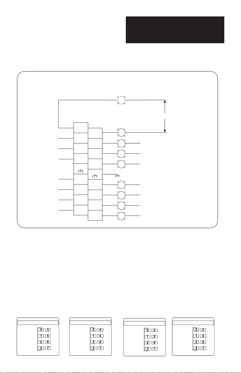
Isolated-Circuit 100/120 V ac/dc Inputs (8)
1746sc-IA8I
VS0 L1 or +VDC
100/120 V ac/dc
Alternative
input device
location
VS1 L2 or DC COM 1
VS2 L2 or DC COM 2
VS3 L2 or DC COM 3
Rack mounting bolt
VS4 L2 or DC COM 4
VS5 L2 or DC COM 5
VS6 L2 or DC COM 6
VS7 L2 or DC COM 7
VS0 L2 or DC COM 0
For IEC Type 1+ devices
that can't support 0.7 A
of inrush current, use an
external 500 Ω 1W
resistor on one input line
to reduce the inrush to
250 mA.
VS1 L1 or +VDC
VS2 L1 or +VDC
VS3 L1 or +VDC
VS4 L1 or +VDC
VS5 L1 or +VDC
VS6 L1 or +VDC
VS7 L1 or +VDC
VAC/VDC
0+
VAC/VDC
1+
VAC/VDC
2+
VAC/VDC
3+
E-GND
VAC/VDC
4+
VAC/VDC
5+
VAC/VDC
6+
VAC/VDC
7+
IN 0–
IN 1–
IN 2–
IN 3–
E-GND
IN 4–
IN 5–
IN 6–
IN 7–
Note -- The input circuits are electrically isolated from each other (the commons are NOT connected
internally). Therefore, up to eight different voltage sources (VS0-VS7) may be used.
Module ID Code = 303
17
Page 20

Installation Instructions
Isolated-Circuit
Discrete Input and Output Modules
Isolated-Circuit 24 Vdc Inputs (8)
1746sc-IB8I
VS0 +VDC
24 Vdc*
Alternative
input device
location
VS1 DC COM 1
VS2 DC COM 2
VS3 DC COM 3
Rack mounting bolt
VS4 DC COM 4
VS5 DC COM 5
VS6 DC COM 6
VS7 DC COM 7
VS0 DC COM 0
VS1 +VDC
VS2 +VDC
VS3 +VDC
VS4 +VDC
VS5 +VDC
VS6 +VDC
VS7 +VDC
VDC
0+
VDC
1+
VDC
2+
VDC
3+
E-GND
VDC
4+
VDC
5+
VDC
6+
VDC
7+
IN 0–
IN 1–
IN 2–
IN 3–
E-GND
IN 4–
IN 5–
IN 6–
IN 7–
Note — The input circuits are electrically isolated from each other (the commons are NOT connected
internally). Therefore, up to eight different voltage sources (VS0–VS7) may be used.
* Inputs are bipolar and may be connected without regard to polarity.
Module ID Code = 324
18
Page 21

Installation Instructions
Isolated-Circuit
Discrete Input and Output Modules
Isolated-Circuit 48 Vdc Inputs (8)
1746sc-IC8I
VS0 +VDC
48 Vdc*
Alternative
input device
location
VS1 DC COM 1
VS2 DC COM 2
VS3 DC COM 3
Rack mounting bolt
VS4 DC COM 4
VS5 DC COM 5
VS6 DC COM 6
VS7 DC COM 7
VS0 DC COM 0
VS1 +VDC
VS2 +VDC
VS3 +VDC
VS4 +VDC
VS5 +VDC
VS6 +VDC
VS7 +VDC
VDC
0+
VDC
1+
VDC
2+
VDC
3+
E-GND
VDC
4+
VDC
5+
VDC
6+
VDC
7+
IN 0–
IN 1–
IN 2–
IN 3–
E-GND
IN 4–
IN 5–
IN 6–
IN 7–
Note — The input circuits are electrically isolated from each other (the commons are NOT connected
internally). Therefore, up to eight different voltage sources (VS0–VS7) may be used.
* Inputs are bipolar and may be connected without regard to polarity.
Module ID Code = 324
19
Page 22

Installation Instructions
Isolated-Circuit
Discrete Input and Output Modules
Isolated-Circuit 200/240 V ac/dc Inputs (8)
1746sc-IM8I
VS0 L1 or +VDC
200/240 V ac/dc
Alternative
input device
location
VS1 L2 or DC COM 1
VS2 L2 or DC COM 2
VS3 L2 or DC COM 3
Rack mounting bolt
VS4 L2 or DC COM 4
VS5 L2 or DC COM 5
VS6 L2 or DC COM 6
VS7 L2 or DC COM 7
VS0 L2 or DC COM 0
For IEC Type 1+ devices
that can't support 0.7 A
of inrush current, use an
external 500 Ω 1W
resistor on one input line
to reduce the inrush to
250 mA.
VS1 L1 or +VDC
VS2 L1 or +VDC
VS3 L1 or +VDC
VS4 L1 or +VDC
VS5 L1 or +VDC
VS6 L1 or +VDC
VS7 L1 or +VDC
VAC/VDC
0+
VAC/VDC
1+
VAC/VDC
2+
VAC/VDC
3+
E-GND
VAC/VDC
4+
VAC/VDC
5+
VAC/VDC
6+
VAC/VDC
7+
IN 0–
IN 1–
IN 2–
IN 3–
E-GND
IN 4–
IN 5–
IN 6–
IN 7–
Note — The input circuits are electrically isolated from each other (the commons are NOT connected
internally). Therefore, up to eight different voltage sources (VS0–VS7) may be used.
Module ID Code = 304
20
Page 23
Installation Instructions
Isolated-Circuit
Discrete Input and Output Modules
Isolated-Circuit 120/240 Vac Outputs (8)
1746sc-OAP8I
VS0 L1
Alternative
output device
VS1 L1
VS2 L1
VS3 L1
VS4 L1
VS5 L1
VS6 L1
VS7 L1
VAC
0
VAC
1
VAC
2
VAC
3
E-GND
VAC
4
VAC
5
VAC
6
VAC
7
OUT 0
OUT 1
OUT 2
OUT 3
E-GND
OUT 4
OUT 5
OUT 6
OUT 7
location
Rack mounting bolt
120/240 Vac
VS0 L2
VS1 L2
VS2 L2
VS3 L2
VS4 L2
VS5 L2
VS6 L2
VS7 L2
Note — The output circuits are electrically isolated from each other (the commons are NOT connected
internally). Therefore, up to eight different voltage sources (VS0–VS7) may be used.
Module ID Code = 1905
Interpreting Your Module’s LED Indicators
On the 1746sc-IA8I, -IB8I, -IC8I, and -IM8I, each status indicator (0–7)
illuminates when the proper signal is received at the corresponding input
terminal.
1746sc-IA8I
INPUT
STATUS
ISOLATED 100/120V AC/DC
1746sc-IB8I
INPUT
STATUS
ISOLATED 24VDC
1746sc-IC8I
INPUT
STATUS
ISOLATED 48 VDC
1746sc-IM8I
INPUT
STATUS
ISOLATED 200/240V AC/DC
21
Page 24

Installation Instructions
ISOLATED TRIAC 120/240 VAC
OUTPUT
STATUS
FUSE
1746sc-OAP8I
Isolated-Circuit
Discrete Input and Output Modules
On the 1746sc-OAP8I, each status
indicator (0–7) illuminates when the
processor commands the module to turn
on the corresponding output. The
indicators do not necessarily indicate the
presence or absence of AC power at an
output. The Blown-Fuse indicator
illuminates when any 1 of the 8 output
fuses blows.
Checking For Blown Fuses (1746sc-OAP8I only)
If a fuse blows on the 1746sc-OAP8I, the following occurs:
1. The blown-fuse LED indicator illuminates (provided your module is
receiving power from the chassis).
2. The module indicates to the logic controller’s input image table which
fuse has blown. This allows for fuse monitoring and smart power-down
sequencing of equipment after a circuit failure.
You can verify that a fuse has opened by visually checking the fuses, shown
below. Turn all power off, and replace blown fuses with the specified replacement part only. Substitutes are not acceptable.
Replaceable Fuses (F1–F8)
22
3 A, 250 V, 2 AG SLO-BLO
Littelfuse part 229003
OAP8I
F1
F2
F3
F4
F5
F6
F7
F8
Page 25

Installation Instructions
Isolated-Circuit
Discrete Input and Output Modules
Getting Technical Assistance
If you need technical assistance, please review the troubleshooting information in Allen-Bradley’s system-level Installation and Operation Manual
before calling your local distributor or Spectrum Controls. Except for the 8
replaceable fuses (1 for each output) on the 1746sc-OAP8I, these modules
contain no user-serviceable parts, and if necessary, should be returned to
Spectrum Controls for repair.
WARNING
!
Note that your module contains electronic components which are susceptible to damage from
electrostatic discharge (ESD). An electrostatic charge can accumulate on the surface of
ordinary plastic wrapping or cushioning material. In the unlikely event that the module
should need to be returned to Spectrum Controls, please ensure that the unit is
enclosed in approved ESD packaging (such as static-shielding / metallized bag or black
conductive container). Spectrum Controls reserves the right to void the warranty on any unit
that is improperly packaged for shipment.
For further information or assistance, please contact your local distributor, or call the Spectrum
Controls Customer Satisfaction department at (425) 746-9481 from 8:00 A.M. to 5:00 P.M.,
Pacific Time.
EXPLOSION HAZARD
Substituting components may impair suitability for Class I, Division 2.
23
Page 26

Installation Instructions
Isolated-Circuit
Discrete Input and Output Modules
Notice
The products and services described in this publication are useful in a wide variety of applications.
Therefore, the user and others responsible for applying the products and services described
herein are responsible for determining their acceptability for each application. While efforts have
been made to provide accurate information within this publication, Spectrum Controls assumes
no responsibility for the accuracy, completeness, or usefulness of the information contained
herein. Under no circumstances will Spectrum Controls be responsible or liable for any damages
or losses, including indirect or consequential damages or losses, arising out of either the use
of any information contained within this publication or the use of any product or service referenced
herein. No patent liability is assumed by Spectrum Controls with respect to the use of any of
the information, products, circuits, programming, or services referenced herein. The information
contained in this publication is subject to change without notice.
Limited Warranty
Spectrum Controls warrants that its products are free from defects in material and workmanship
under normal use and service, as described in Spectrum Controls literature covering this
product, for a period of 1 year. Spectrum Controls obligations under this warranty are limited
to replacing or repairing, at its option, at its factory or facility, any product which shall, in the
applicable period after shipment, be returned to the Spectrum Controls facility, transportation
charges prepaid, and which after examination is determined, to the satisfaction of Spectrum
Controls, to be thus defective. This warranty shall not apply to any such equipment which shall
have been repaired or altered except by Spectrum Controls or which shall have been subject
to misuse, neglect, or accident. In no case shall Spectrum Controls liability exceed the purchase
price. The aforementioned provisions do not extend the original warranty period of any product
which has either been repaired or replaced by Spectrum Controls.
Declaration Of Conformity
Available upon request.
Page 27

Installation Instructions
Isolated-Circuit
Discrete Input and Output Modules
Ask your distributor about these other Allen-Bradley compatible products
from Spectrum Controls:
Catalog No. Description
1746sc-INI4vi Isolated-Channel Analog Inputs (4)
1746sc-INI4i Isolated-Channel Analog Inputs (4)
1746sc-INO4vi Isolated-Channel Analog Outputs (4)
1746sc-INO4i Isolated-Channel Analog Outputs (4)
1746sc-IA8I Isolated-Circuit 100/120 V ac/dc Inputs (8)
1746sc-IB8I Isolated-Circuit 24 Vdc Inputs (8)
1746sc-IC8I Isolated-Circuit 48 Vdc Inputs (8)
1746sc-IM8I Isolated-Circuit 200/240 V ac/dc Inputs (8)
1746sc-OAP8I Isolated-Circuit 120/240 Vac Outputs (8)
1771sc-IMI16 Isolated-Circuit 200/240 V ac/dc Inputs (16)
1771sc-OMI16 Isolated-Circuit 120/240 Vac Triac Outputs (16)
The ENCOMPASS logo and SLC 500 are trademarks of Allen-Bradley Company, Inc. Copyright © 1998-2004 Spectrum
Controls, Inc. All rights reserved. Specifications subject to change without notice. Printed in U.S.A.
Publication 0300146-08 Rev. J May 2004
U.S.A. Headquarters
Spectrum Controls, Inc.
P.O. Box 5533
Bellevue, Washington 98006
Fax: (425) 641-947
Tel: (425) 746-9481
Each Current or Voltage Selectable
Current only
Each Current or Voltage Selectable
Current only
Each Fuse Protected
Web Site: http://www.spectrumcontrols.com
Email: spectrum@spectrumcontrols.com
 Loading...