

Page 1

Owner’sGuide 0300181-05 Rev .G
™
SLC 5 00
F
LOWMETER INPUT
Catalog Numbers
1746sc-CTR4
1746sc-CTR8
50 KHZ C
M
OUNTER
ODULE
/
Page 2

Page 3

Important Notes
1. Please read all the information in this owner’s guide before installing
the product.
2. The information in this owner's guide applies to hardware and
firmware version 1.0 or later.
3. This guide assumes that the reader has a full working knowledge of
the relevant processor.
Notice
The products and services described in this owner's guide are useful in a
wide variety of applications. Therefore, the user and others responsible
for applying the products and services described herein are responsible
for determining their acceptability for each application. While efforts
have been made to provide accurate information within this owner's
guide, Spectrum Controls assumes no responsibility for the accuracy,
completeness, or usefulness of the information herein.
Under no circumstances will Spectrum Controls be responsible or liable
for any damages or losses, including indirect or consequential damages
or losses, arising out of either the use of any information within this
owner's guide or the use of any product or service referenced herein.
No patent liability is assumed by Spectrum Controls with respect to the
use of any of the information, products, circuits, programming, or
services referenced herein.
The information in this owner's guide is subject to change without notice.
Limited Warranty
Spectrum Controls warrants that its products are free from defects in
material and workmanship under normal use and service, as described in
Spectrum Controls literature covering this product, for a period of 1 year.
The obligations of Spectrum Controls under this warranty are limited to
replacing or repairing, at its option, at its factory or facility, any product
which shall, in the applicable period after shipment, be returned to the
Spectrum Controls facility, transportation charges prepaid, and which
after examination is determined, to the satisfaction of Spectrum Controls,
to be thus defective.
This warranty shall not apply to any such equipment which shall have
been repaired or altered except by Spectrum Controls or which shall
have been subject to misuse, neglect, or accident. In no case shall the
liability of Spectrum Controls exceed the purchase price. The
aforementioned provisions do not extend the original warranty period of
any product which has either been repaired or replaced by Spectrum
Controls.
Page 4

Page 5

Contents
Overview And Specifications......................................................... 7
General Features And Benefits.......................................................................................................... 7
Detailed Specifications ....................................................................................................................... 9
Table 1.1. Electrical specifications—module .................................................................................................. 9
Table 1.2. Physical specifications ...................................................................................................................10
Table 1.3. Environmental specifications ........................................................................................................10
Installing And W iring Your Module............................................. 1 1
Avoiding Electrostatic Damage........................................................................................................ 12
Determining Power Requirements..................................................................................................12
Table 2.1. Backplane current consumed........................................................................................................ 13
Selecting a Rack Slot ........................................................................................................................ 13
Setting your Jumpers ....................................................................................................................... 13
Inserting Your Module Into The Rack ........................................................................................... 14
Wiring Your Module ........................................................................................................................ 15
Terminal Block Wiring ...................................................................................................................................17
Labeling And Re-Installing The Terminal Block
(if it is removed) .......................................................................................................................... 18
Things To Consider Before Using
Your Module ............................................................................. 19
Module ID Code................................................................................................................................ 19
Table 3.1 Module ID codes ..............................................................................................................................19
Module Addressing........................................................................................................................... 20
Figure 3.1.......................................................................................................................................................... 20
Operating Modes .............................................................................................................................. 22
Table 3.2 Module operating modes ............................................................................................................... 22
Input Configurations........................................................................................................................ 22
Gate Modes........................................................................................................................................ 24
Channel Turn-On,
Turn-Off, and
Reconfiguration Times ............................................................................................................... 24
Response to Slot Disabling............................................................................................................... 24
Channel Configuration, Data,
and Status.................................................................................. 27
Configuring Each Input Channel ................................................................................................... 27
Output Register - Scale and Limit Data Values............................................................................. 34
Input Registers - Channel Data...................................................................................................... 37
Page 6

Check each output
channel’s
configuration and status............................................................................................................. 39
Programming / Application Examples ......................................... 43
Sample Counter Configuration
Simple Linear Counter
(10,000 Limit):............................................................................................................................. 43
Ring Counter Sample ....................................................................................................................... 44
Sample Configuration
Simple Ring Counter
w/ Flags (20k Limit): .................................................................................................................. 45
Using Preset Values
with Extended Mode................................................................................................................... 46
Using Scaling with
Count and Rate Outputs:........................................................................................................... 46
Application:
Meter Proving ............................................................................................................................. 47
Application Note:
Factor Data Errors ..................................................................................................................... 48
Testing Your Module .................................................................... 51
Inspecting Your Module................................................................................................................... 51
Disconnecting Prime Movers ........................................................................................................... 52
Powering Up...................................................................................................................................... 52
Interpreting The LED Indicators.................................................................................................... 53
Figure 6.1. LED block ..................................................................................................................................... 53
Operation........................................................................................................................................... 53
Table 6.1 Channel Status LED Blink Codes.................................................................................................53
Codes.................................................................................................................................................. 54
No Signal............................................................................................................................................ 54
Troubleshooting ................................................................................................................................ 55
Figure 6.2. Problem resolution flowchar t ..................................................................................................... 55
Maintaining Your Module
And Ensuring Safety................................................................. 57
Preventive Maintenance ................................................................................................................... 57
Safety Considerations....................................................................................................................... 57
Declaration of Conformity............................................................................................................... 59
Page 7

Chapter 1
Overview And Specifications
The 1746sc-CTR4 and the 1746sc-CTR8 are 4 and 8 channel Counter/
Flow Meter modules. The modules are suitable for general purpose
counter and flow meter applications that require a large number of input
channels and high accuracy. The module supports both AC and DC input
signal types. The counter functions include programmable control of the
counter including start, stop, reset, preset control and user defined flags.
The input levels for the counter mode are 5, 12, and 24 volts DC. The
Flow Meter mode is compatible with variable reluctance AC input. This
differential AC input will count AC zero crossing signals from 50 mV to
75 V peak.
Read this chapter to familiarize yourself with your counter module. This
chapter covers:
General Features And
Benefits
• General features and benefits
• Detailed specifications
• 8 Input Channels or 4 Channels of Quadrature Encoders
• 4 External Counter enable inputs
• Input voltage ranges: AC (50mv–75V peak), 5 Vdc, 12 Vdc, 24 Vdc
• Input uency: AC 50 KHz Max, DC 50 KHz Max
• Maximum count value: ±32 K or ±8 M
• Programmable Scaling, K, M, R Factor
• Channel update time of 4 msec/channel
• Rate output mode (Integrer and Floating Point)
• Counter logic level state
• Programmable Counter functions: start/stop/reset/present
• Programmable counter Alarm flags and zero flags
• 3 Selectable filters: 15 KHz, 30 KHz, 50 KHz
• Channel to back Plane isolation of 1000 Vdc
Page 8

8 SLC 500™ 50 KHz Counter / Flowmeter Input Module
Increased Accuracy and Reliability
The counter module offers ±1 count accuracy and ±1% or better
frequency measurement accuracy. Programmable functions allow the
user to define counter ranges and flags to accommodate process-specific
requirements. Full speed counter operation of over 50kHz is possible.
Reduced System Costs
High Channel density allows for lower resource usage. Eight channels
consume the resources associated with a standard two channel module.
State-of-the-Art Performance
These modules incorporate state of the art Programmable Gate Array
technology that allows high circuit density and functionality. The
module uses proprietary Allen-Bradley technology, so they operate and
perform like the latest Allen-Bradley products. They also provide high
resolution, user-programmable range settings, continuous temperature
compensation (no field calibration), software configuration,
programmable output limits, and programmable safe states in case of a
fault.
Detailed Specifications
Table 1.1. Electrical specifications—module
SpecificationSpecification
Specification Description
SpecificationSpecification
Configuration 4/8 Channel of differential counter inputs 2/4 Channels of
quadrature encoding 2/4 Input enable Control lines
Input Modes DC counter, AC flow meter,
Voltage Range AC 0-30VP 5VDC 12VDC 24VDC
VIL -50mV 1V 3V 5
VIH +50mV 3.5V 9V 13
Vmax (CE) ±75V ±75V ±75V ±75V
Vmax (UL) ±100V ±100V ±100V ±100V
Current Range 5mA Max @ 120V
Input Impedance Rin > 10 MOhm when within -10V to +12V range
Rin = 25kOhm when outside of -10V to +12V range
Cin 100pF Input Filter Off
Cin 1000pF Input Filter On
Counter Speed DC Inputs 0 Hz to 50kHz
AC Inputs 0 Hz to 50kHz
Input Frequency DC Inputs 1 Hz to 50kHz
AC Inputs 1 Hz to 50kHz
Counter Enable Input VI L 1.0V max
VI H 3.5V min
Page 9

Chapter 1: Overview And Specifications 9
Vmax 75 V
Input impedance 25K ohms
Input Filter
Digital Filter 50kHz (Default)
Digital Filter 30kHz
Analog Filter 15kHz
Min Pulse Time
DC mode 8us
External Enable/Disable Enable and Disable setup time = 20us
Channel Update Tim e
Counter Output Scaling OFF ON
Rate Output
Rate Instantaneous Mode 4.0 5.6 (msec per channel)
Rate Average Mode 1.0 1.0 (sec per channel)
Accuracy
Count mode ± 1 Count
Rate (Instant) ± 1% @ 50KHz, .001% @ 1Hz
Rate (Average) ± 1Hz
4.0 5.6 (msec per channel)
Maximum Count Value
Low Range -32,768 to +32,767
High Range -8,388,608 to +8,388,607
Fault detection Over & under range status bits, for all modes.
Page 10

10 SLC 500™ 50 KHz Counter / Flowmeter Input Module
Data Format
Counter mode Max Binary Value: -8,388,608 to +8,388,607
Rate mode Max Binary Value: -32,768 to +32,767
Isolation
Channel to Rack 1000 VDC Continuous Optical & magnetic
Channel to Channel 0VDC
Input Protection Max input voltage ±100VDC, 150VAC peak
Max input current ± 5mA@100Vp
Power Requirements
Internal rack +5v 175mA 225mA
Internal rack +24V 75mA 125mA
T able 1.2. Physical specifications
LED Indicators
Module Status The Module Status LED indicates the status of the power up
self test. The LED is on when the module is ready. Any self
test error is indicated with a blink code.
Channel Status CTR4 - 4 Green LEDs
CTR8 - 8 Green LEDs
The 8 Channel LED’s indicates that a channel is enabled.
T erminal Block 24 pin removable connector
Wire Size One 12 AWG to 28 AWG wires
CTR4 CTR8
Torque .5nm, 4.5 lb.in.
T able 1.3. Environmental specifications
T emperature / Humidity Ranges
Operating Temperature 0-60degC (32-140F)
Storage Temperature -40 to +85degC (-40 to + 185F)
Humidity Temperature 5% to 95% non-condensing
Certifications UL508 CUL& Class 1, Div II, (CSA equiv .)
FCC Part 15 class A CE Compliance to EN
61010-1 and EN 61131-2, EN50081-2, EN50082-2.
Page 11

Chapter 2
Installing And Wiring Your Module
Read this chapter to install and wire your module. This chapter covers:
• avoiding electrostatic damage
• determining power requirements
• selecting a rack slot
• inserting your module into the rack
• wiring your module
Important - For UL and CUL compliance, power and input/output (I/O)
wiring must be in accordance with Class I, Division 2, wiring methods
[Article 501-4 (b) of the National Electrical Code , NFPA 70] and in
accordance with the authority having jurisdiction. Also, you must
observe the warnings shown below. Failure to observe these warnings
can cause personal injury.
WARNING
EXPLOSION HAZARD
Substitution of components may impair suitability for
!
Class I, Division 2;
When in hazardous locations, turn off power before replacing or
wiring modules;
Do not disconnect equipment unless power has been switched
off or the area is known to be non-hazardous.
Page 12

12 ControlLogix™ Counter Module
The following documents contain information that may help you as you
install and wire your module:
• National Electrical Code, published by the National Fire Protection
Association of Boston, MA
• IEEE Standard 518-1977, Guide for the Installation of Electrical
Equipment to Minimize Electrical Noise Inputs to Controllers fr o m
External Sources
• IEEE Standard 142-1982, Recommended Practices for Grounding of
Industrial and Commercial Power Systems
• Noise Reduction T echniques in Electronic Systems, by Henry W. Ott;
published by Wiley-Interscience of New York in 1976
Avoiding Electrostatic
Damage
Guard against electrostatic damage by observing the following
precautions:
CAUTION
!
ELECTROSTATICALLY SENSITIVE COMPONENTS
• Before handling the module, touch a grounded object to
rid yourself of electrostatic charge.
• When handling the module, wear an approved wrist strap
grounding device.
• Handle the module from the front, away from the
backplane connector. Do not touch backplane
connector pins.
• Keep the module in its static-shield container when not
in use or during shipment.
Failure to observe these precautions can degrade the module’s
performance or cause permanent damage.
Page 13

Determining Power
Requirements
Chapter 2: Installing And Wiring Y our Module 13
The backplane of the system can provide both 5 Vdc and 24 Vdc power .
The following table shows the maximum current consumed by your module
when using these power sources:
Table 2.1. Backplane current consumed
Catalog Number 5 Vdc 24 Vdc
1756sc-CTR8 230 mA 75 mA
Use T able 2.1 to calculate the total load on the system power supply . For
more information, see the Allen-Bradley system Installation and
Operation Manual.
Selecting a Rack Slot
Two factors determine where you should install your module in the rack:
ambient temperature and electrical noise. When selecting a slot for your
module, try to position your module:
• in a rack close to the bottom of the enclosure (where the air is cooler)
• away from modules that generate significant heat, such as 32-point
input/output modules
• in a slot away from ac or high-voltage dc modules, hard contact
switches, relays, and ac motor drives
• away from the rack power supply (if using a modular system)
Remember that in a modular system, the processor always occupies the
first slot of the rack.
Page 14

14 ControlLogix™ Counter Module
!
When inserting your module into the rack, you do not need to remove the
supplied 36-position terminal block from the module. If, however, you do
remove the terminal block, use the write-on label to identify your
module’s location.
CAUTION
POSSIBLE EQUIPMENT OPERATION
Before installing or removing your module, always disconnect
power from the SLC 500 system and from any other source to
the module (in other words, don’t “hot swap” your module), and
disconnect any devices wired to the module.
Failure to observe this precaution can cause unintended
equipment operation and damage.
To remove the terminal block, unscrew the two retaining screws at the
top and bottom of the terminal block, and using a screwdriver or needlenose pliers, carefully pry the terminal block loose.
T o insert your module into the rack, follow these steps:
1. Align the circuit board of your module with the card guides at the top
and bottom of the chassis.
Page 15

Chapter 2: Installing And Wiring Y our Module 15
2. Slide your module into the chassis until both top and bottom retaining
clips are secure. Apply firm even pressure on your module to attach it
to its backplane connector. Never force your module into the slot.
Cover all unused slots with the Card Slot Filler, Allen-Bradley part
number 1746-N2.
To remove your module, press the retaining clips at the top and bottom
of your module and slide it out.
Wiring Your Module
To wire the terminal block, you need:
• a small, flat-blade screwdriver
• Belden 8761 (shielded, twisted pair) cable or equivalent
CAUTION
!
Before wiring the terminal block, take some time to plan your system:
• Ensure that the SLC 500 system is installed in a NEMA-rated enclosure
and that the SLC 500 system is properly grounded.
• Route the field wiring away from any other wiring and as far as possible
from sources of electrical noise, such as motors, transformers,
contactors, and ac devices. As a general rule, allow at lease 6 in.
(about 15.2 cm) of separation for every 120 Vac of power.
POSSIBLE EQUIPMENT OPERATION
Before wiring your module, always disconnect power from the
SLC 500 system and from any other source to the module.
Failure to observe this precaution can cause unintended
equipment operation and damage.
• Routing the field wiring in grounded conduit can reduce electrical
noise further.
• If the field wiring must cross ac or power cables, ensure that they
cross at right angles.
To wire your module, follow these steps:
1. Determine the length of cable you need to connect a channel to its field
device. Remember to include additional cable to route the drain wire and
Page 16

16 ControlLogix™ Counter Module
foil shield to their ground points. Connect only one end of the shield to
the module.
2. At each end of the cable, strip some casing to expose the individual
wires.
3. Trim the exposed signal wires to 2 in. lengths. Strip about 3/16 in.
(about 5 mm) of insulation away to expose the end of each wire.
4. At one end of the cable, twist the drain wire and foil shield together,
bend them away from the cable, and apply shrink wrap.
5. At the other end of the cable, cut the drain wire and foil shield back to
the cable and apply shrink wrap.
Foil Shield and Drain Wire
Insulation
Clear Wire
Black Wire
6. Connect the wires to the terminal block and field device as shown in
the following figures and table. The recommended maximum torque is
4.5 in-lb (0.565 Nm) for all terminal screws.
Page 17

Chapter 2: Installing And Wiring Y our Module 17
T o guard against electrostatic damage and improve chassis grounding,
connect one of the shield pins on the terminal block of your module to
the chassis itself.
7. Repeat steps 1 through 6 for each channel on your module.
A system may malfunction due to a change in its operating environment.
After installing and wiring your module, check system operation. See the
Allen-Bradley system Installation and Operation Manual for more
information.
Terminal Block Wiring
Note: Channels 4-7 are only available on the 1746sc-CTR8 module.
Note: A pull up resistor may be necessary for open collector inputs. Refer
to Chapter 6 for additional information.
Page 18

18 ControlLogix™ Counter Module
Labeling And ReInstalling The
Terminal Block
(if it is removed)
The supplied label is mounted on the module door. This label helps
ensure that the terminal block is wired correctly for the module.
Once you have wired your module and properly labeled install the
terminal block on your module:
1. Align the terminal block with the receptacle.
2. Insert the terminal block and press firmly at the top and bottom until it
is properly seated.
3. Screw in the two retaining screws on the top and bottom of the
terminal block.
Page 19

Chapter 3
Things To Consider Before Using
Your Module
This chapter explains how the module and the SLC processor
communicate through the processor’s I/O image tables. It also describes
the module’s input filter characteristics. Topics discussed include:
• module ID code
• module addressing
• operating modes
• input configurations
• gate modes
• channel turn on / turn off / reconfiguration timing
Module ID Code
• response to slot disabling
Before using your module, you must configure the slot your module is in
by entering the module’s ID code in APS or RS Logix. Enter your
module’s ID code, select “other” from the list of modules on the APS or
RS Logix system I/O configuration display and enter your module’s ID
code at the prompt.
The module ID code for your input module is:
Table 3.1 Module ID codes
Catalog Number Module ID code
1746sc-CTR4 10200
1746sc-CTR8 10401
Page 20

20 SLC 500™ 50 KHz Counter / Flowmeter Input Module
Module Addressing
SLC 5/02-05
Data Files
Output Image
Input Image
SLC 5/02-05
Data Files
Output Image
Input Image
Slot e
Slot e
Slot e
Slot e
CTR-8
Output
Scan
Input
Scan
CTR-4
Output
Scan
Input
Scan
The CTR-8 module uses 32 input and 32 output registers, and the CTR-4
module uses 16 input and 16 output registers. Both modules use Class
III mode operation and cannot be used with Class I operation. The
following memory map shows you how the SLC processor’s output and
input tables are defined for the module. The SLC 5/01 processor does
not support Class III operation and is not compatible with this module.
This module is not suitable for use in remote rack applications with ASB
modules due to the input / output word size.
Figure 3.1Image table
Bit 0 Address
Word 0 O:e.0
Word 1 O:e.1
Word 2 O:e.2
Word 3 O:e.3
Word 28 O:e.28
Word 29 O:e.29
Word 30 O:e.30
Word 31 O:e.31
Word 0 I:e.0
Word 1 I:e.1
Word 2 I:e.2
Word 3 I:e.3
Word 28 I:e.28
Word 29 I:e.29
Word 30 I:e.30
Word 31 I:e.31
Bit 0 Address
Bit 0 Address
Word 0 O:e.0
Word 1 O:e.1
Word 2 O:e.2
Word 3 O:e.3
Word 12 O:e.12
Word 13 O:e.13
Word 14 O:e.14
Word 15 O:e.15
Word 0 I:e.0
Word 1 I:e.1
Word 2 I:e.2
Word 3 I:e.3
Word 12 I:e.12
Word 13 I:e.13
Word 14 I:e.14
Word 15 I:e.15
Bit 0 Address
Counter
Module
Image Table
Output Image
32 Words
Input Image
32 Words
Counter
Module
Image Table
Output Image
16 Words
Input Image
16 Words
Bit 15
Channel 0 Configuration Word
Channel 0 Preset / M Factor
Channel 0 Limit / K Factor
Channel 0 Rate Lim / R Factor
Channel 7 Configuration Word
Channel 7 Preset / M Factor
Channel 7 Limit / K Factor
Channel 7 Rate Lim / R Factor
Channel 0 Output Low (MSW)
Channel 0 Output High (LSW)
Channel 0 Frequency
Channel 0 Status Word
Channel 7 Output Low (MSW)
Channel 7 Output High (LSW)
Channel 7 Frequency
Channel 7 Status Word
Bit 15
Bit 15
Channel 0 Configuration Word
Channel 0 Preset / M Factor
Channel 0 Limit / K Factor
Channel 0 Rate Lim / R Factor
Channel 3 Configuration Word
Channel 3 Preset / M Factor
Channel 3 Limit / K Factor
Channel 3 Rate Lim / R Factor
Channel 0 Output Low (MSW)
Channel 0 Output High (LSW)
Channel 0 Frequency
Channel 0 Status Word
Channel 3 Output Low (MSW)
Channel 3 Output High (LSW)
Channel 3 Frequency
Channel 3 Status Word
Bit 15
Page 21

Chapter 3: Things T o Consider Before Using Y our Module 21
O:4.2
File type
Slot
Word
Element
Delimiter
Word
Delimiter
Output Image - Configuration Words
Thirty-two (CTR-8) or sixteen (CTR-4) words of the SLC processor’s
output image table are reserved for the module. For the CTR8, output
image words 0-31 are used to configure input channels 0-7. For the
CTR4, output image words 0-15 are used to configure input channels 0-4.
Each output image word configures a single channel, sets the preset, limit
and scale factors and can be referred to as a configuration word. Each
word has a unique address based on the slot number assigned to the
module.
Example Address - If you want to configure channel 2 on the module
located in slot 4 in the SLC chassis, your address would be O:4.4.
Chapter 4, Channel Configuration, Data, and Status, gives you detailed
bit information about the data content of the configuration word.
Input Image - Data Words and Status Words
Count data, Rate data, and status are given in four input words for each
channel.
Chapter 4, Channel Configuration, Data, and Status, gives you detailed
bit information about the content of the data word and the status word.
Page 22

22 SLC 500™ 50 KHz Counter / Flowmeter Input Module
Operating Modes
Input Configurations
The module’s operating mode determines the number of available counters
and which inputs are attached to them. There are two operating modes
and their input assignments are summarized in the table below .
Table 3.2 Module operating modes
Operational Mode CTR8 (CTR4) Input Channel Configuration
Single Ended Input 8 (4) Channels – One per input
Single Ended Up/Down 4 (2) Channels - One Input / One Direction Discrete
Quadrature Input 4 (2) Channels - T wo per input.
Input configurations determine how the 8 inputs cause the counter to
increment or decrement. The four available configurations are:
• Uni-Directional (up)
• Bi-Directional (up and down using two channels)
• X1 Quadrature Encoder
• X4 Quadrature Encoder
See the “Summary of A vailable Counter Configurations” for the input
configurations available for the counters, based on operating mode.
Uni-Directional
With this configuration, the input increments in an upward direction. All
8 channels may be configured in the unidirectional mode. Every clock
pulse will increment the counter on the rising edge. Note: The direction
of the counter may be inverted by setting the Count Direction bit described
in the Configuration chapter .
Bi-Directional
The bidirectional counter requires 2 input channels. In this mode one
nd
channel is used as the counter input and the 2
channel is used to
determine the count direction. The counter will increment when the
Direction Channel value is 0, and will decrement when the Counter
Direction Channel value is 1.
X1 Quadrature Encoder
The quadrature mode requires 2 input channels. When a quadrature
encoder is attached to an input channel pair, A and B, the count direction
is determined by the phase angle between inputs A and B. If A leads B,
the counter increments. If B leads A, the counter decrements. (The
counter changes value only on one edge of input 1.) The counter
increments once per quadrature cycle.
Page 23
Chapter 3: Things T o Consider Before Using Y our Module 23
Note: The X1 Quadrature mode provides additional Anti-Jitter
circuitry. This distinguishes between a valid quadrature sequence
and an invalid sequence due to electrical noise or jitter. Jitter can
occur if a quadrature encoder stops rotating right at an input sensor
trip point. This can cause additional unwanted clock pulses. The X1
quadrature mode can detect invalid transitions and filter these out.
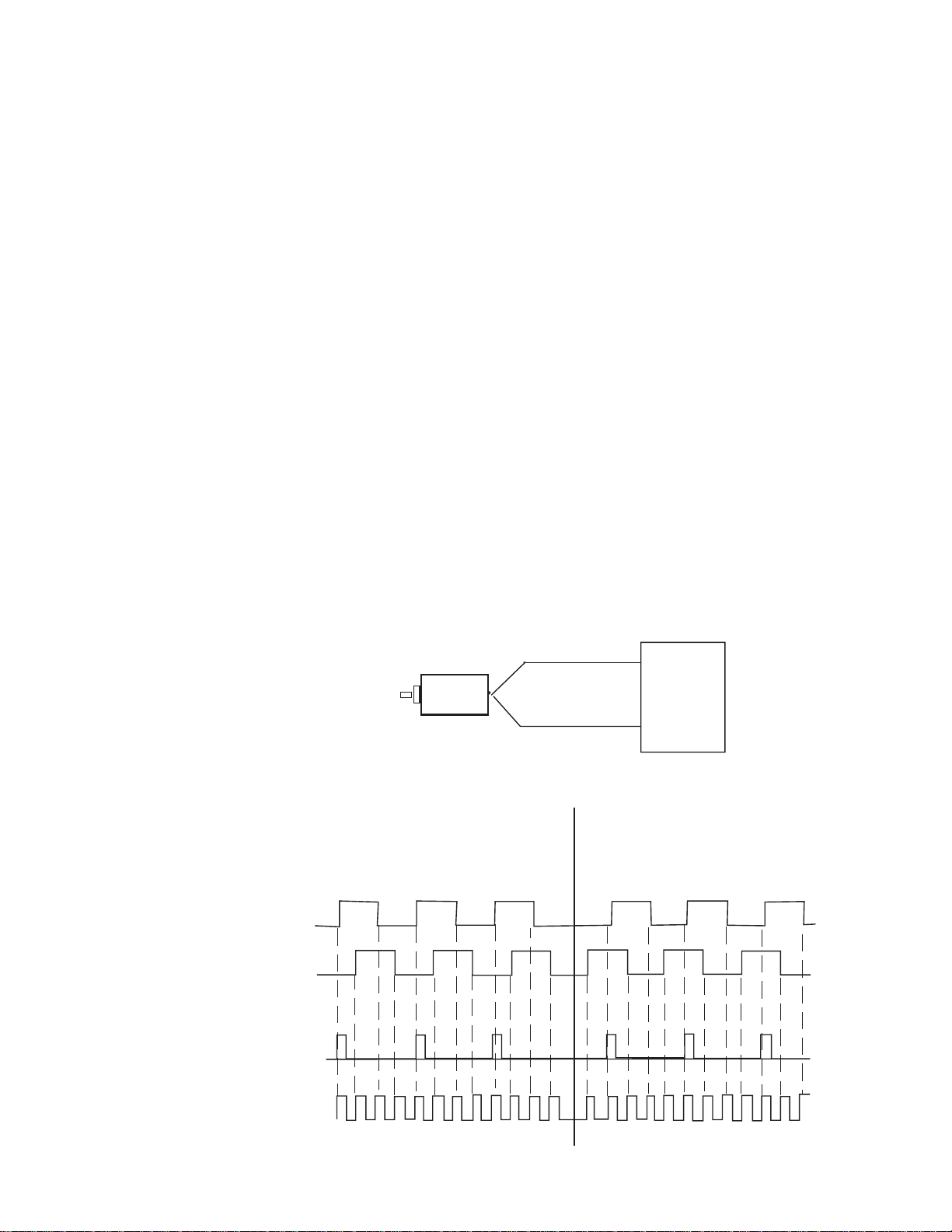
X4 Quadrature Encoder
Like the X1 quadrature encoder, the count direction is determined by the
phase angle between inputs A and B. If A leads B, the counter
increments. If B leads A, the counter decrements. However, the counter
changes value on the rising and falling edges of inputs A and B. The
counter increments four times per quadrature cycle.
Note: In the X4 Quadrature mode, invalid signals are not detected. A
broken input wire, jitter or noise on the input can cause additional
counts to be registered. The modules response to four possible error
conditions are listed below:
A
B
Input A is active while input B is stuck high: Module will count down on input A transitions.
Input A is active while input B is stuck low: Module will count down on input A transitions.
Input A is stuck high while input B active: Module will count down on input B transitions.
Input A is stuck low while input B is active: Module will count up on input B transitions.
A
Input A
B
Quadrature
Input B
Encoder
Forward Rotation Reverse Rotation
x1 Count
x4 Count
1
2
3
1 2 3 4 5 6 7 8 9 10 11 12
2
10
11 10 9 8 7 6 5 4 3 2 1 0
Page 24

24 SLC 500™ 50 KHz Counter / Flowmeter Input Module
Gate Modes
Channel Turn-On,
Turn-Off, and
Reconfiguration Times
There are two methods to gate (start/stop) your counter, hardware and
software. The counter’s gate/preset mode determines what, if any, gating
is applied to the counter and what, if any , conditions will preset the counter
to the preset value.
External Hardware Gate Lines:
There are four external inputs, one for each pair of input channels, that
may be used to start and stop the counter. Each external gate is pulled
low internal to the module. A low input allows each pair of counter
channels to operate. The count enable line is compatible with 5, 12, and
24 VDC inputs. If pulled high with one of these inputs the pair of
counter channels are disabled.
Note: The module’s Channel LED’s only indicate the state of the counters
start/stop bit. They do not indicate that state of the external hardware
gate.
Counter Start / Stop Bit
This bit allows the counter to continue to count up or down from its
present value. Starting, or enabling this bit wil not override the external
counter input.
The time required for the module to recognize a new configuration for a
channel is one module update time.
Response to Slot
Disabling
Turn-off time requires up to one module update time.
Reconfiguration time is the same as turn-on time.
By writing to the status file in the modular SLC processor, you can
disable any chassis slot. Refer to your SLC programming manual for the
slot disable/enable procedure.
CAUTION
!
POSSIBLE EQUIPMENT OPERATION
Always understand the implications of disabling a module
before using the slot disable feature.
Failure to observe this precaution can cause unintended
equipment operation.
Page 25

Chapter 3: Things T o Consider Before Using Y our Module 25
Input Response
When a counter slot is disabled, the counter module continues to update
its input image table. However, the SLC processor does not read input
from a module that is disabled. Therefore, when the processor disables
the counter module slot, the module inputs appearing in the processor
table is not read. When the processor re-enables the module slot, the
current state of the module inputs are read by the processor during the
subsequent scan.
Output response
The SLC processor may change the counter module output data
(configuration) as it appears in the processor output image. However,
this data is not transferred to the counter module. The outputs are held in
their last state. When the slot is re-enabled, the data in the processor
image is transferred to the counter module.
Page 26

26 SLC 500™ 50 KHz Counter / Flowmeter Input Module
Page 27

Channel Configuration, Data,
and Status
Read this chapter to:
• configure each input channel
• set user-defined scale limits
• monitor each input channel
• check each output channel’s configuration and status
Chapter 4
Configuring Each Input
Channel
The Data Register format uses Class 3 operation. Class 3 mode allows
the module to use 32 input words and 32 output words of data, as listed
below. After installing your module, you must configure each channel
by setting bit values in each configuration word. Output words 0 through
31 of the output image file (addresses O:e.0 – O:e.31) configure channels
0-7 respectively and (addresses O:e.0 - O:e.15) for channels 0 - 3 of the
CTR4.
Page 28

28 SLC 500™ 50 KHz Counter / Flowmeter Module
Figure 4.1 - Configuration W ord
Address
O:e.3
O:e.13
O:e.16
O:e.19
15
Channel 0 Configuration WordO:e.0
Channel 0 Preset / M FactorO:e.1
Channel 0 Limit / K FactorO:e.2
Channel 0 Rate Limit / R Factor
Channel 1 Configuration WordO:e.4
Channel 1 Preset / M FactorO:e.5
Channel 1 Limit / K FactorO:e.6
Channel 1 Rate Limit / R FactorO:e.7
Channel 2 Configuration WordO:e.8
Channel 2 Preset / M FactorO:e.9
Channel 2 Limit / K FactorO:e.10
Channel 2 Rate Limit / R FactorO:e.11
Channel 3 Configuration WordO:e.12
Channel 3 Preset / M Factor
Channel 3 Limit / K FactorO:e.14
Channel 3 Rate Limit / R FactorO:e.15
Channel 4 Configuration Word
Channel 4 Preset / M FactorO:e.17
Channel 4 Limit / K FactorO:e.18
Channel 4 Rate Limit / R Factor
0
CTR4
CTR8
Channel 5 Configuration WordO:e.20
Channel 5 Preset / M FactorO:e.21
Channel 5 Limit / K FactorO:e.22
Channel 5 Rate Limit / R FactorO:e.23
Channel 6 Configuration WordO:e.24
Channel 6 Preset / M FactorO:e.25
Channel 6 Limit / K FactorO:e.26
Channel 6 Rate Limit / R FactorO:e.27
Channel 7 Configuration WordO:e.28
Channel 7 Preset / M FactorO:e.29
Channel 7 Limit / K FactorO:e.30
Channel 7 Rate Limit / R FactorO:e31
Page 29

Chapter 4: Channel Configuration, Data, and Status 29
Figure 4.2 - Configuration W ord Settings
Address
15 14 13 12 11 10 9 8 7 6 5 4 3 2 1 0
Channel 0 Configuration WordO:e.x
Filter
0 =Normal
1 = Program
0 = Neg
1 = Preset
0 = Zero
1 = Preset
Directrion
Roll over to
Roll under to
Scale / Limit Mode
0 = Normal
1 = Inverted
0=Standard
1=Extended
0 = 50kHz
1 = 30kHz
Count Size
Stop in Limit
0 = Off
1 = On
0 = Off
1 = On
Stop on Zero
00 = UniDirect
01 = BiDirect
10 = Quad x1
11 = Quad x4
00 = AC
01 = 5 V
10 = 12V
11 = 24V
Count Mode
Input Range
Counter Start/Stop: (Configuration Bit 0)
This bit allows the counter to continue to count up or down from its
present value.
Note: Starting or enabling the counter with this bit will not override the
external counter enable input. The external input enable and the counter
start bit must both be enabled for the counter to continue counting. If
either the counter stop bit or the external input enable line are disabled
the counter will hold it’s last value and stop counting.
Rate Mode
Reset Flags
0 = Normal
1 = Reset
0 = Instant
1 = Average
Preset
Counter Enable
0 = Start
1 = Stop
0 = Off
1 = On
Counter Preset: (Configuration Bit 1)
When this bit is set, the value in counter preset word is loaded into the
counter. The counter preset can be used to set the counter to an initial
starting value. The bit should be set for at least 2 I/O scans. The bit can
be held on until the data in the counter data is verified to be equal to the
preset value. The counter will hold the preset value until the counter
preset bit is turned off. At this time normal counter functions will resume.
Note: A Counter Reset function is achieved by using the Counter
Preset, when the preset value is set to zero.
Refer to the Preset and Limit Data Value Configuration section for more
information about loading your preset value.
Page 30

30 SLC 500™ 50 KHz Counter / Flowmeter Module
Reset Flags: (Configuration Bit 2)
The reset flags command is performed when this bit is set. Reset flags
affects the counter zero, counter limit and counter maximum flags
(Status word bits 8, 6, and 5 respectively .) These particular flags remain
high, regardless of the counter behavior, until a reset is performed. This
allows adequate time to read the flags after an event has occured.
If user Counter Limit is set to 0 (0 indicates undefined), these flags will
remain high until reset:
Count is equal to zero or counter decremented down through zero flag
(Status word bit 8).
Count up or down through the maximum count flag
(Status word bit 5).
If a Counter Limit is never set (Status word bit 6) the flags will not
annunciate.
If user Counter Limit is set to a non-zero value ( User defined limit), these
flags are will remain high until reset:
Count is equal to zero or counter decremented down through zero flag
(Status word bit 8).
Count up or down through the limit flag (Status word bit 6).
And these flags do not remain high:
Maximum count flag (Status word bit 5) is set if count value is
exactly equal to 32,767 (16 bit) or 8,388,607 (24 bit). Otherwise it is
clear.
Rate Mode: (Configuration Bit 3)
Refer to Appendix A for Floating Point Rate Mode
Rate - Average:
When the rate mode bit is set to a “1” the rate detection circuit is in
“Rate Average” mode. The rate average mode counts the number of
input transitions over a 1 second interval and calculates the input rate
averaged over the 1 second interval. The rate average mode is slow, in
that it reports updated rates at once per second. However this mode is
accurate to ± 1 count over the full range of measurement.
Figure 4.4 - One Second Rate Average
One Second Average of Periods
Page 31

Chapter 4: Channel Configuration, Data, and Status 31
One Period
Rate - Instant:
When this bit is reset to “0” the rate detection circuit operates in “Instant”
mode. Instant measurements are fast, in that they calculate a rate based
on one cycle. However the accuracy of the measurement degrades as
the input clock rate goes up to 50KHz, and any jitter within one cycle will
be measured.
Figure 4.3 - One Period Rate Measurement
The accuracy while operating in the average mode is ±1 count. When
using the Instant mode the accuracy is ±1% at 50kHz and improves to
±0.002% at 100Hz. The graph below shows the rate accuracy in Hertz vs.
Frequency.
Frequency Error
Frequency Error
250
200
150
100
Error
Error in Hz
50
Error
0
0 10,000 20,000 30,000 40,000 50,000 60,000
-50
Instant Rate Mode Error
Frequency
Frequency
Input Rate
Input Range: (Configuration Bits 4-5)
This group of 2 bits selects one of 4 input ranges. Each range is selected
for a given system voltage level. Each range has its own counter trip
level. Refer to the Specifications section of this manual for input limit
information.
Table 4.2 Input Range Selection Bits (O:e.4-O:e.5)
Mode Bit Setting Range
AC 00 50 mV to 30 VAC
DC 01 0 to 5 VDC
D C 10 0 to 12 VDC
D C 11 0 to 24 VDC
Note: The input range must configured in channel pairs to operate
properly. Pairs are channels 0-1, 2-3, 4-5, 6-7.
Note: You should allow at least 1 scan time for input range
information to be updated at the PLC.
Page 32

32 SLC 500™ 50 KHz Counter / Flowmeter Module
Count Mode: (Configuration Bits 6-7)
The Count Mode bit selects 1 of 4 types of counter operation.
The Unidirectional counter mode is configured as an Up or Down
counter. The module will support 8 unidirectional input channels. Every
clock pulse increments the counter .
Note: The direction of the count can be inverted by the COUNT
DIRECTION bit (see bit 12).
The Bidirectional counter requires 2 channels inputs. In this mode one
nd
channel is used as the counter input and the 2
channel is used to
determine the count direction. The counter will increment when the
Direction input channel is a 1, and will decrement the counter when the
Direction input channel is a 0. Even channels, 0,2,4,6 are inputs. Odd
channels, 1,2,5,7 control direction. Both channels within a pair must be
configured for bidirectional mode. Bidirectional encoding will report the
same count value on each channel’s output.
When the counter is set to Quadrature mode channels will be configured
into quadrature encoding pairs. Both channels within a pair must be
configured for quadrature mode. Quadrature encoding will report the
same quadrature count value on each channel’s output. Quadrature mode
allows for the channels to count up or down depending on the quadrature
encoding direction. The COUNT DIRECTION bit can invert the
direction of the quadrature encoding. The QUAD X1 mode clocks the
counter once every quadrature cycle. The QUAD X4 mode clocks the
counter 4 times every quadrature cycle, once for every edge transition on
both input lines.
Table 4.3 Count Mode Settings
ModeMode
Mode
ModeMode
ChannelsChannels
Channels
ChannelsChannels
BitsBits
Bits
BitsBits
FunctionFunction
Function
FunctionFunction
UniDirectional 8 00 Unidirectional Up/Down counter
BiDirectional 4 01 Bidirectional Up/Down counter
Quad X1 4 1 0 Quadrature Mode 1 count/cycle
Quad X4 4 11 Quadrature Mode 4 counts/cycle
Stop on Zero: (Configuration Bit 8)
This bit, when set, will hold the counter output at zero. When the
counter counts down to zero the counter will either count through zero or
hold its output at zero counts, until the Zero flag is cleared. When cleared
the counter will continue to count.
Note: The stop on zero function only applies to counts decrementing
down through zero.
Page 33

Chapter 4: Channel Configuration, Data, and Status 33
Stop on Limit: (Configuration Bit 9)
This bit, when set, will hold the counter output at its limit value. When the
counter counts to the limit value it will either rollover to zero, or hold its
output at the limit value, until the Limit Flag is cleared. When released the
counter will continue to count. If the user defined limit register is equal to
zero, the limit is internally set to 32,767 (Normal Mode) or 8,388,607
(Extended Mode).
Filter Frequency: (Configuration Bit 10)
This bit selects the cutoff frequency that the input channel will allow.
When the bit is set to 1 the filter will be set to limit input noise to 30kHz.
This selection should be used for Counter or Flow Meter applications
running at speeds less than 30kHz. When this bit is set to 0 the channel
will run at full speed and filter noise above 50kHz.
A 15kHz hardware filter is also available by using the onboard jumper
settings. To activate the filter for Channels 0-3 remove the shunt on the
JP2 jumper. To activate the filter for Channels 4-7 (CTR8 only) remove
the shunt on JP3.
Count Size: (Configuration Bit 11)
This bit determines the maximum counter value. When set to 0 the
channel counter will count up to ±32K (1 word of data). When the
maximum value of 32,767 is reached, the Maximum Count flag is set,
and rollover will occur at this point. When the count size is extended to
±8,388,607 by setting this bit to 1, the Counters Maximum flag is
extended to ±8M and data output is formed using two words. The
counter Preset and Limit values are also extended to ±8M. This means
that the resolution of the Preset and Limit values are set in blocks of 256
counts (8bits) beacause only one word is available for each limit. This
allows the preset and limit values to cover the whole ±8M bit range.
-32K-8M +8M
Extended Normal
0
+32K
Normal Extended
Count Direction: (Configuration Bit 12)
This bit inverts the current direction of the counter. When set to 0 this bit
has no effect on the direction. When toggled to 1 the count direction in
unidirectional mode is forced to count down. In bidirectional mode or
Quadrature mode the counter direction is reversed from it’s current
direction.
Counter Roll Over: (Configuration Bit 13)
When the counter exceeds the maximum count, the counter will roll over
the top. When the counter rolls over it can roll over to a starting value
of zero, or it can start at the user defined preset value. When this bit is
set to 0 the counter will roll over to zero. When set to 1 the counter will
roll over to the preset value. If the stop on limit flag is set the counter will
not roll over until the flag is released. When released the counter will roll
over to zero or its preset value.
Page 34

34 SLC 500™ 50 KHz Counter / Flowmeter Module
Counter Roll Under: (Configuration Bit 14)
When the counter rolls under zero it can continue to count down into
negative numbers, or it can start at the user defined preset value. When
this bit is set to 0 the counter will continue to count down through zero
into negative numbers. When set to 1 the counter will roll under to the
preset value. If the stop on zero flag is set the counter will not roll under
until the flag is released. When released the counter will roll under to its
maximum or preset value.
Program Scale Factors: (Configuration Bit 15)
Each channel has four words which configure the behavior of that
channel, the configuration word, the Preset / M factor word, the counter
Limit / K factor word, and the Rate Limit / R Factor word. Normally the
2nd, 3rd and 4th words are Preset, Counter Limit, and Rate Limit
respectively. However, when values are input into the scale factors and
bit 15 of the configuration word is set the module programs the scale
factors into non-volatile memory. When scale factors are programmed the
R and K/M Factor Flags are set in the status register.
Output Register - Scale
and Limit Data Values
When using the Counter Preset, Counter Limit, Rate Limit or K / M / R
Factors you must input the value that is appropriate for your application.
The values follow each channels configuration word and use the next
three configuration words. For example, Channel 0 has a configuration
word address of O:e.0, Preset address of O:e.1, a Counter Limit address
of O:e.2, and a Rate Limit address of O:e.3. Refer to the Input word
data diagram in the beginning of this chapter for channel specific address
information.
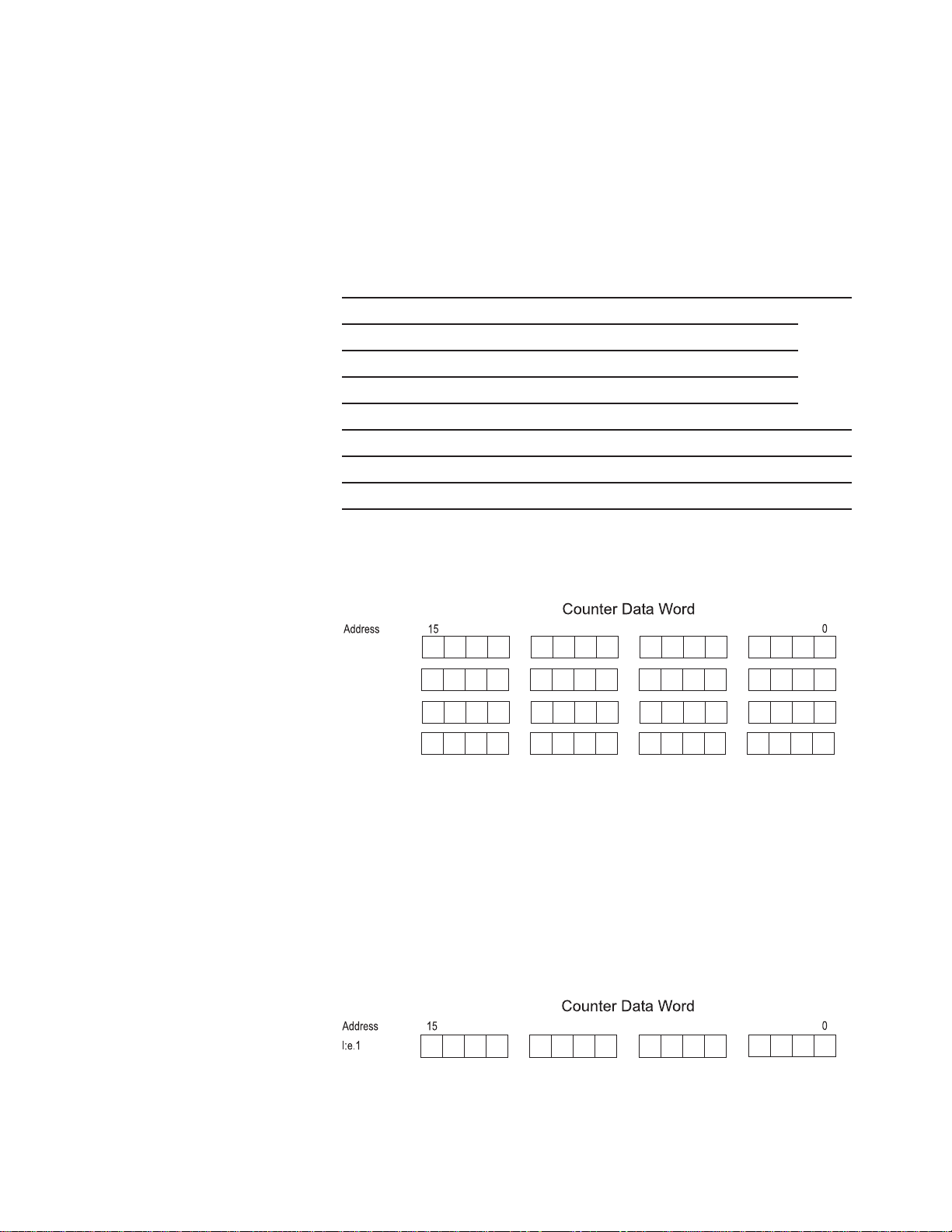
Figure 4.5 - Preset / Limit / Rate Limit Words
Address
O:e.z Rate Limit / R Factor
15
Counter Preset / M FactorO:e.x
Counter Limit / K FactorO:e.y
Counter Preset / M Factor:
The counter preset function is used in Normal operation mode. This input
data word is used in conjunction with the scale/limit mode bit. When this
bit is set, the value in the counter preset word is loaded into the counter.
The counter preset can be used to set the counter to an initial starting
value. The bit should be set for at least one I/O scan. The bit can be held
on until the data in the counter data is verified to be equal to the preset
value. The counter will hold the preset value until the counter preset bit
is turned off. At this time normal counter functions will resume. The
preset value is typically set less than the Counter limit value.
0
Page 35

Chapter 4: Channel Configuration, Data, and Status 35
Note: In extended count mode (counts up to +/- 8M) the preset will be
multiplied by 256 internally such that a user preset of 1000 will result
in a preset of 25600. This allows the preset value to cover the whole
+/- 8 million count range.
In program scale factor mode an M Factor is stored in the module’s nonvolatile memory . If an M Factor is defined (not zero) then the data value
output for the counter value will be COUNT x (M Factor/10,000). A
value of zero must be written to the M Factor to disable this feature.
Figure 4.7 - Limit / M Factor Word
Address
15
Counter Limit / M FactorO:e.y
0
Example:
An M Factor of 10,200 will increase the output count by 2%.
Output Count = Input Count * 10,200/10,000
Output Count = Input Count * 1.02
Note: When the count size is extended to ±8M using Configuration Bit
11, the Counters Maximum flag is extended to ±8M. The counter
Preset and Limit values are also extended to ±8M. This means that
the resolution of the Preset and Limit values are set in blocks of 256
counts (8bits). This allows the preset and limit values to cover the
whole ±8M bit range. Refer to the applications section of this
manual for more information about setting limit and scale values.
Counter Limit / K Factor:
The counter limit mode is used in Normal operation mode. This input data
word is used in conjunction with the Scale / Limit Mode enable bit. When
the counter limit bit is set, the counter limit flag will be active. When the
counter value is greater then or equal to the Limit value the Counter Limit
flag bit will be set. If the Stop On Limit bit is set the counter will not
exceed the counter limit.
Note: When operating in standard count mode, if the K Factor x
Count Limit is > 32767 a configuration error will occur.
Note: In extended counter mode the limit will be multiplied by 256
internally such that a user limit of 1000 will result in a limit of
256,000.
In program scale factor mode a K factor is stored in the module’ s nonvolatile memory . If a K Factor is defined (not zero) then the data value
output for the counter is the counter value divided by the K Factor. A
value of zero must be written to the K Factor to disable this feature.
Figure 4.6 - Preset / K Factor Word
Address
15
Counter Preset / K FactorO:e.x
0
Page 36

36 SLC 500™ 50 KHz Counter / Flowmeter Module
Rate Limit / R Factor:
The rate limit function is used in the Normal operation mode. The Rate
Limit represents a target maximum value for rate. When the rate value is
greater then or equal to the rate limit value the Rate Limit flag bit will be
set.
In program scale factor mode an R Factor is stored in the module’s nonvolatile memory. If an R Factor is defined (not zero) then the data value
output for the counter value will be Rate / R Factor. A zero value must
be written to the R Factor to disable this feature.
Figure 4.8 - Rate Limit / R Factor Word
Address
15
Rate Limit / R FactorO:e.z
Refer to the applications section of the manual for limit and scale
examples.
Floating Point Rate Mode is activated by setting the Rate Factor to -1.
See Applendix A for information about the floating point mode.
0
Page 37
Input Registers Channel Data
Chapter 4: Channel Configuration, Data, and Status 37
The channel data consists of 4 words, the lower counter data value, the
upper counter data value, the rate data value and the channel status data.
Table 4.4 - Data Word Addresses
CTR8 CTR4 Scale/Limit Value
I:e.0 to I:e.3 I:e.0 to I:e.3 0 Channel MSW, LSW , Rate Data, Status Reg
I:e.4 to I:e.7 I:e.4 to I:e.7 1 Channel MSW, LSW , Rate Data, Status Reg
I:e.8 to I:e.11 I:e.8 to I:e.11 2 Channel MSW , LSW, Rate Data, S tatus Reg
I:e.12 to I:e.15 I:e.12 to I:e.15 3 Channel MSW , LSW, Rate Data, S tatus Reg
I:e.16 to I:e.19 (n/a) 4 Channel MSW, LSW , Rate Data, St atus Reg
I:e.20 to I:e.23 (n/a) 5 Channel MSW, LSW , Rate Data, St atus Reg
I:e.24 to I:e.27 (n/a) 6 Channel MSW, LSW , Rate Data, St atus Reg
I:e.28 to I:e.31 (n/a) 7 Channel MSW, LSW , Rate Data, St atus Reg
Figure 4.9 - Data Words
8
9
I:e.w
I:e.x
I:e.y
I:e.z
Counter MSW
Counter LSW
Rate Output
Status Output
Counter Output Register, High word:
This output data register contains the upper word of the counters
accumulator. This register is a 16 bit word in binary 2’s complement
format. When operating in the extended count mode, ±8M counts, the
high word is equal to the counter value/1,000 and the low word is the
remainder. For example, a count of 40,123 would result in a high word
equal to 40, and the low word equal to 123. The high word = 40 and the
low word = 123.
Figure 4.11 -Counter High Word
8
9
Counter Input High
This register is always zero when operating the the standard (32k) count
mode.
Page 38

38 SLC 500™ 50 KHz Counter / Flowmeter Module
Counter Output Register, Low word:
This output data register contains the lower word of the counter
accumulator. This register is a signed16 bit word in binary 2’ s complement
format and will allow count values up to ±32K. This word is used in
conjunction with the counter’s upper output word when in the extended
count mode. Bit 15 represents the sign for each word. When the counter
is operating in the extended mode, the low and high words are used
together to form a composite number that extends the counter to ±8M.
The low word represents counts up to 1000 and the high word represents
counts that carry over 1000. (When the counter is configured in Extended
mode.)
Actual count = (Value of the high word x 1000) + (V alue of the low word).
Figure 4.10 -Counter Low W ord
8
9
Counter Input Low
Rate Output Register word:
Refer to Appendix A for floating point rate mode.
This output data register contains the rate value while operating in rate
mode. This register is a 16 bit word in binary 2’ s complement format and
represents the input value. Note that if the R Factor is present the output
date value is represented as the Rate / R Factor. Rates greater than
32kHz must use a R factor otherwise overflow will occur. If the R factor
is set to 2 and your input rate is 50kHz, the data output word will read
25,000.
Figure 4.12 -Counter Rate Word
8
9
Rate Input Value
Page 39

Check each input
channel’s
configuration and status
Chapter 4: Channel Configuration, Data, and Status 39
Output Channel Status Flags
Figure 4.13 Counter Output - Channel Status Flags
Address
0 = OK
1 = Error
0= OK
1= Error
15 14 13 12 11 10 9 8 7 6 5 4 3 2 1 0
Channel 0 Status WordI:e.3
Channel 1 Status WordI:e.7
Channel 2 Status WordI:e.11
Channel 3 Status WordI:e.15
Channel 4 Status WordI:e.19
Channel 5 Status WordI:e.23
Channel 6 Status WordI:e.27
Channel 7 Status WordI:e.31
Rate Max
Rate Limit
0 = Zero
1 = Set
0 = Zero
1 = Set
System Error
K or M Factor
Configuration Error
Rate Limit / R Factor
0 = Reset
1 = Set
0 = Reset
1 = Set
0 = Reset
1 = Set
Rate Zero
0 = Reset
1 = Set
Count Zero
0 = Reset
1 = Set
Count Max
Count Size
Count Limit
Count Preset
0 = Standard
1 = Extended
0 = Reset
1 = Set
0 = Reset
1 = Set
Direction Invert
Counter Enable
Count Direction
0 = Start
Counter Input State
1 = Stop
0 = Low
1 = High
0 = Up
1 = Down
0 = Normal
1 = Invert
Page 40

40 SLC 500™ 50 KHz Counter / Flowmeter Module
Counter Start/Stop Echo: (Status Bit 0)
This bit echo’s the setting of the Counter Enable bit set in the channels
control register. The counter enable bit allows the counter to continue to
count up or down from its present value.
Counter Input State: (Status Bit 1)
This bit shows the current value of the input state. The state of the input
will be sampled at the end of the current update cycle. For rapidly
changing counter inputs the state of this bit could be either high or low
depending on the exact time of measurement. The purpose for this bit is
to provide slow counter feedback and single count diagnosis. This bit can
also be used as a general purpose digital input line back to the PLC.
Counter Direction State: (Status Bit 2)
This bit shows the current direction of the counter. The state of the
counter direction will be sampled at the end of the current update cycle.
For rapidly changing counter inputs the state of this bit could be either
high or low depending on the exact time of measurement. The purpose
for this indicator is to provide quadrature detection feedback to aid in
system diagnosis.
Count Direction Invert Bit echo: (Status Bit 3)
This bit echo’s the state of the Count Direction bit set in the channel
configuration register. The count direction status echo’s the state of the
invert bit. It does not determine if the count is going up or down.
Count Size Selection echo (Status Bit 4)
This bit echo’s the state of the maximum counter value selected in the
configuration register. When zero the channel counter is in standard
mode and will count up to ±32K (1 word of data). When set to 1 the is
in the extended mode and will have a maximum value of 8M which is
formed using the MSW and LSW data words..
Counter Max Flag: (Status Bit 5)
The flag is set when the maximum count, based on Normal or Extended
mode, is reached. Refer to the Reset Flags, Configuration Bit 2, in the
configuration word section of this chapter for a description of this flag’s
operation.
Counter Limit Flag: (Status Bit 6)
The flag is set when the user defined count limit is reached. Refer to the
the configuration word section of this chapter for a description of this
flag’s operation.
Counter Preset Echo: (Status Bit 7)
The flag is echos the state of the preset bit on the configuration register.
Page 41

Chapter 4: Channel Configuration, Data, and Status 41
Counter Zero Flag: (Status Bit 8)
The flag is set when the counter counts down through zero. Refer to the
configuration word section of this chapter for a description of this flag’s
operation.
Max Rate Flag: (Configuration Bit 9)
The max rate flag is set when the input rate exceeds its maximum range
of 32,767kHz. This flag indicates that the input counter rate is over the
valid range of the module and that the value indicated in the rate data
register may not be correct. This flag will stay on until the input rate
falls below the rate limit. If a Rate R Factor of 2 or more is used the
Max Rate Flag will be set at an input frequency of 50kHz
Rate Limit Flag: (Configuration Bit 10)
When the rate value is greater than or equal to the Rate Limit value the
Rate Limit flag bit will be set. This flag will stay on until the input rate
falls below the rate limit.
Rate Zero Flag: (Configuration Bit 11)
The rate zero flag is set when the input rate is zero. This flag can be
used to flag an input fault condition. The rate zero flag is set when no
input is detected for 2 seconds.
K Factor / M Factor Set Flag: (Configuration Bit 12)
This bit indicates that a non zero K or M factor value has been written to
the module’s non-volatile memory. This value will be use to scale the
input counter data. When a K or M factor is set all count data will be
scaled by the K or M factor data.
R Factor Set Flag: (Configuration Bit 13)
This bit indicates that a non zero R factor value has been written to the
module’s non-volatile memory . This R factor value is used to scale the
rate data or enable the floating point rate mode.
Configuration Error Flag: (Configuration Bit 14)
This flag is set when the channel configuration word is set to an illegal
state. An example would be if one channel was configured for
quadrature detection and its quadrature pair was not. In this case both
channels would have their configuration flags set until the configuration
word was corrected. All counter data will be set to zero when an illegal
configuration occurs.
System Error Flag: (Configuration Bit 15)
This flag is set when the module detects a system error. System Errors
are reported when the module can’t complete its power up self test or
detects some other on line error, like a watchdog time out.
Page 42

42 SLC 500™ 50 KHz Counter / Flowmeter Module
Page 43

Sample Counter
Configuration
Simple Linear
Counter
(10,000 Limit):
Chapter 5
Programming / Application Examples
Learning to configure your counter to meet your application requirements
will require knowledge of counter configuration, ladder logic programming
and data management. Read this chapter to familiarize yourself with how
to use the advanced features of your module for:
This configuration for Channel 0 of the counter module will allow the user
to count from zero to a maximum value of 10,000 counts.
10,000
-32K-8M -8M
0
+32K
T o facilitate this you must input a Limit of 10,000 counts. This cycle will
continue, without stopping , with these configuration settings.
Channel 0 - Output Register Configuration (O:e.0)
Output Register Configuration
Config. Bit Description Bit Setting Description
*15 Normal 0 Normal Mode
14 Roll Under 0 Roll to Neg. #s
13 Roll Over 1 Roll to Preset
12 Direction 0 (Default) No Inversion
1 1 Count Size 0 (Default) ±32K Std.
10 Freq. Filter 0 (Default) 50kHz
9 Stop on Limit 0 (Default) No Stop
8 Stop on Zero 0 (Default) No Stop
6/ 7 Count Mode 00 (Default) Unidirectional
4/ 5 Input Range 00 (Default) 50mV-30VAC
3 Rate. Mode 0 (Default) Instant Mode
2 Reset Flags 0 (Default) Of f
1 Counter Preset 0 (Default) Off
No scale factors or associated flags are used. The input range is based on
your input signal type. The filter on the input rate defaulted to 50kHz.
Configuration W ord
O:e.2 Counter Limit 10,000
W e have set the limit to 10,000.
Page 44

44 SLC 500™ 50 KHz Counter / Flowmeter Module
0 Count 10,000
Roll Over
Note: If we change Configuration Bit 9 to 1 the counter will reach the
limit and then hold its value until the Limit Flag is cleared. Then it
will roll to 0, and continue counting to 10,000. Each time the limit is
reached the flag must be reset before proceeding.
Note: If we toggle Configuration Bit 12 the counter counts in a
downward direction. It will start at 0 and count to -32,768. It will
then Roll Under to +32,767. If Configuration Bit 14 is set the
counter will Roll Under to this Preset Value.
Ring Counter
Sample
The figure below demonstrates a ring counter operation. In a ring counter
operation, the count value changes between zero and maximum. If, when
counting up, the counter reaches the maximum value, it rolls over to zero.
If, when counting down, the counter reaches zero, it rolls under to the
maximum value.
Maximum Value Zero
Count Down
Ring Counter
Rollover
Count Up
Page 45

Sample
Configuration
Simple Ring Counter
w/ Flags (20k Limit):
Chapter 5: Ladder Program Examples 45
This configuration for the counter module will allow the user to count from
a minimum value of 0 to a limit value of 20,000 counts Each time a
revolution has occurred the counter limit flag will be set. Your ladder
program may use this flag to increment an accumulator, thus counting
revolutions. The flag must be reset before another complete revolution
occurs otherwise the accumulator can not be incremented.
Channel 0 Output Register Configuration (O:e.0)
Config. Bit Description Bit Setting Description
*15 Normal 0 Normal Mode
14 Roll Under 1 Preset
13 Roll Over 1 Roll to Zero
12 Direction 0 (Default) No Inversion
1 1 Count Size 0 (Default) ±32K
10 Freq. Filter 0 (Default) 50kHz
9 Stop on Limit 0 No Stop
8 Stop on Zero 0 (Default) N/A
6/ 7 Count Mode 00 (Default) Uni-Directional
4/ 5 Input Range 00 (Default) 50mV-30VAC
3 Rate Mode 0 (Default) Instant
2 Reset Flags 0 (Default) Toggle each Rev.
1 Counter Preset 0 (Default) Off
Output Word - O:e.1 Counter Preset= 20,000
Output W ord - O:e.2 Counter Limit = 20,000
A ring counter is configured by setting the preset and limit values to the
same count and setting the roll over to zero and roll under to preset bits.
Zero must always be the starting point and the maximum value must
always be positive.
20K Ring Counter
020,000
Rollover
Flag Set
on Each
Revolution
Count Up
Page 46

46 SLC 500™ 50 KHz Counter / Flowmeter Module
The above figure illustrates counting in a clockwise direction.
Using Preset Values
with Extended Mode
The Counter Preset and Counter Limit functions are affected by the
Count Size Configuration Bit 11. The default counter range is ±32K but
may be extended to ±8M.
Using Scaling with
Count and Rate
Outputs:
-32K-8M +8M
Extended Normal
0
+32K
Normal Extended
When operating in the extended range, ±8M, all Counter Preset and
Counter Limit are multiplied by 256. The resolution of the Preset and
Limit values in the standard mode is one count. The resolution in the
extended mode is 256 counts.
Count Size ±32K ±8M Description
Preset V alue 1000 256,000 = 1000 x 256
Limit Value 10 0 2560 = 100 x 256
Count Output:
Counter output scaling is applied using the K & M scale factors. When a
scale factor is applied to the counter the Counter Output Register = (Raw
Count * (M factor /10000) * 1/ K Factor). When a scale factor is being
used the Preset and Limit flags are also scaled.
Rate Output:
Rate output scaling is applied using the R scale factors. When a scale
factor is applied to the module the Rate Output Register = Incoming
frequency / R Factor. When a scale factor is being used the Rate Limit
flag is also scaled.
Example:
As an example if a rate factor of R = 2 is programmed into the module.
The Rate Limit value is set to 10KHz
In this example the Rate Limit Flag would be set when the input
≥
frequency is
20KHz.
Rate Limit Flag = Input Frequency * R factor
Page 47
Application:
Meter Proving
Chapter 5: Ladder Program Examples 47
Rate Limit Flag = 10,000Hz * 2 = 20,000Hz
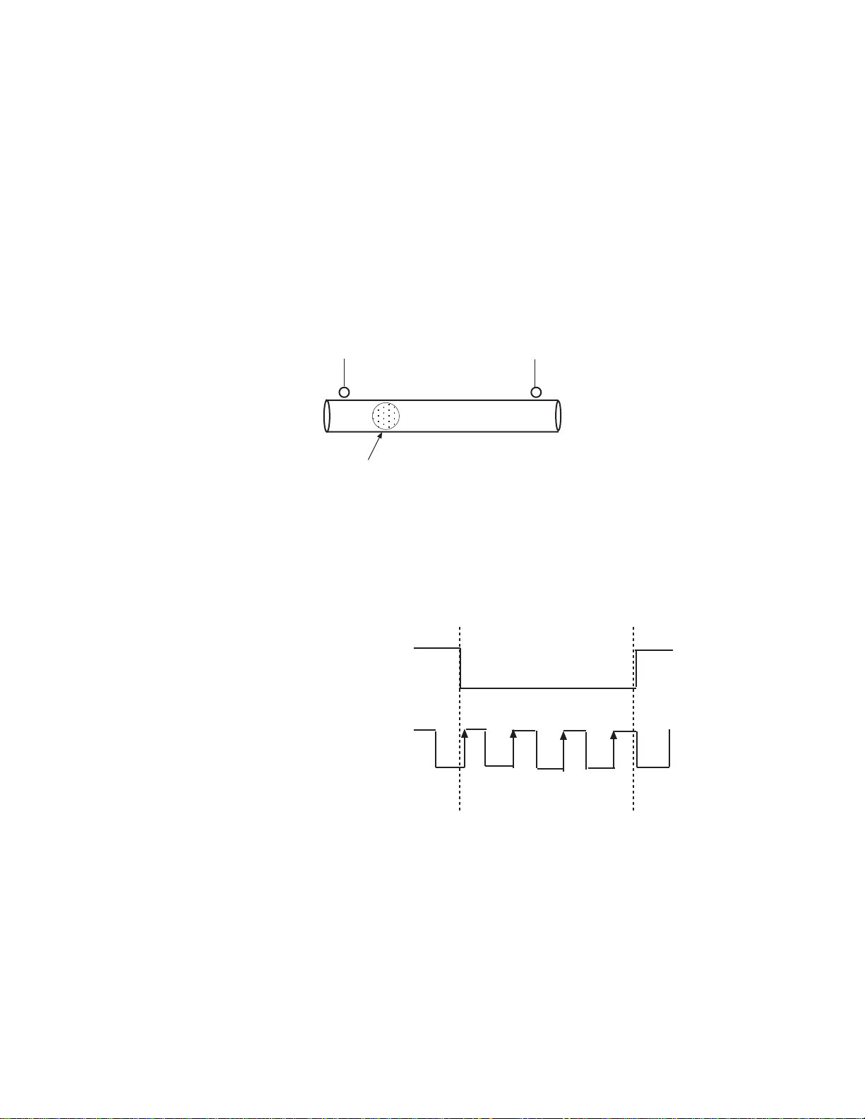
The 1746sc-CTR4/8 module provides a feature that allows the user to
perform meter proving functions. A typical meter proving application
would include two detector sensors that are located a fixed distance from
each other within a section of pipe used specifically for meter proving.
The operation does not disrupt the in situ flowmeter’s operation.
Detector #1
Displacer
Detector #2
Utilizing the external gate enable to start and stop count functions enables
the user to count pulses as fast as 20 microseconds to an accuracy of 1
count.
Here is an example wave form representing the start and stop transitions
on the external gate enable, and the associated pulses that the module
would accumulate:
External Channel Enable
Flow Meter Input
1 2 3 4 NA
Given the above wave form, the module will begin counting the first
positive going input pulse after the external enable input goes low . The
module will accumulate 4 counts in the channel count register and stop
when the external enable input goes high.
Page 48

48 SLC 500™ 50 KHz Counter / Flowmeter Module
The external enable line accommodates 5 Vdc, 12 Vdc and 24 Vdc signals
and is pulled low internally.
Vdc, 24 Vdc and up to 75 Vac inputs.
Application Note:
Factor Data Errors
The 1746sc-CTR4/8 module provides a feature that allows the user to load
M, K and Rate factor values into module memory without consuming
additional control registers. In order to accommodate this feature into the
design, three of the four registers assigned to each channel of the module
are multiplexed with the Counter Preset, Limit and Rate limit values.
If factored data values are inadvertently loaded into the module without
user knowledge of this occurring, the module can appear to be non
functional.
Follow these steps to identify if factored data values have been loaded and
if so, how to clear those values to return the module to default operation.
Use Channel Status registers to identify the presence of Factored
Data values
The counter input accommodates 5 Vdc, 12
Use Bits 12 and 13 in the channel status registers to verify if factored data
is present. If either or both of the bits are set to a one the module has
factor data values loaded.
Here are the address for the channel status registers:
Channel Register
0 I:e.3 (Where e indicates slot where module is installed)
1 I:e.7
2 I:e.11
3 I:e.15
CTR8 only:
4 I:e.19
5 I:e.23
6 I:e.27
7 I:e.31
Clear loaded factor data
Page 49

Chapter 5: Ladder Program Examples 49
In order to clear the factored data 0 must be loaded into the Preset / K
Factor, Limit / M Factor and Limit / R Factor registers. After entering 0
into these registers bit 15 of the module Configuration register
must be toggled from 0 to 1 and then back to 0.
There are 4 registers assigned for each Channels output configuration
word. The first register assigned is the channel configuration register .
The next 3 registers are the Preset / K Factor, Limit / M Factor and Limit
/ R Factor registers respectively.
Refer to Page 24 for detailed information regarding the output
configuration registers and their functions.
Page 50

50 SLC 500™ 50 KHz Counter / Flowmeter Module
Page 51

Chapter 6
Testing Your Module
Read this chapter to prevent potential problems in a systematic and
controlled way. This chapter covers:
• inspecting your module
• disconnecting prime movers
• powering up
• interpreting the LED indicators
• interpreting I/O error codes
• troubleshooting
Inspecting Your Module
Before testing your module, test your SLC 500 system using the
procedures described in your system’s Installation & Operation Manual.
You can prevent many potential problems by simply inspecting your
analog module:
1. Ensure that all wire connections are correct and secure and that no
wires are missing or broken.
CAUTION
!
2. Ensure that the shield for the cable used to wire your module is
properly grounded. Refer to Chapter 2, Installing And Wiring Your
Module, for more information.
FIELD WIRING ERRORS
Before enabling a channel (through your ladder program),
ensure that you have chosen a proper input range for your input
signal.
Failure to observe this precaution can cause improper module
operation or equipment damage.
3. Ensure that the removable terminal block on your module is secure.
Page 52

52 SLC 500™ 50 KHz Counter / Flowmeter Module
Disconnecting Prime
Movers
Before testing your module, ensure that machine motion will not occur:
• Disconnect motor wires at the motor starter or the motor itself. This
lets you test the operation of the starter coil, verifying that the output
circuit is wired correctly and functioning.
• Disconnect solenoids by disengaging the solenoid valves, leaving the
coils connected.
If you cannot disconnect a device in the preferred way, open the output
circuit as close as possible to the motion-causing device.
Example – If you have a relay coil that in turn energizes a motor starter
and you cannot disconnect the motor wires, open the circuit at a point
between the motor starter and the relay contact.
WARNING
!
POSSIBLE UNEXPECTED MACHINE MOTION
Powering Up
During all testing, always disconnect all devices that, when
energized, might cause machine motion.
Failure to observe this precaution can cause equipment damage
or personal injury.
When you apply power to the system, the module status LED should
illuminate, indicating that your module is receiving power and has
completed its onboard self-test. If the LED does not illuminate after
several seconds, your module is not functional. Discontinue testing until
you can get the LED to illuminate.
The most probable reasons for the LED not illuminating are:
• The SLC 500 system is not receiving power from its power supply.
• The rack slot where your module is located is defective.
• Y our module is defective.
Note: It is recommended that the module be powered up prior to
applying a signal to the channel inputs or the channel enable
control lines. When using the module with 24V input devices, input
levels must be less than 12V on module power up. Failure to
adhere to these recommondations may result in inproper module
initialization.
Page 53

Interpreting T he LED
Indicators
Chapter 6: Testing Y our Module 53
Y our module has nine LEDs: eight channel status LEDs (numbered 0–7
for channels 0–7, respectively) and one module status LED.
Figure 6.1. LED block
Operation
CHANNEL
STATUS
MODULE
INPUT
CTR4
0 2
1
3
CHANNEL
STATUS
MODULE
INPUT
CTR8
0 4
1
2
3
5
6
7
The module has 9 (5-CTR4) LED’s that indicate the following…
Module Status LED: 1 Green LED Indicates that the module has
completed its self test and is ready. Module
and self test errors are reported by an error
blink code.
Channel Status LED’s: 8 Green LEDs The channel status LED’s
indicate that the given channel is Enabled.
See table below for blink code.
The Module and Channel Status LEDs produce diagnostic blink codes
when an error occurs. If the Module Status LED produces a blink code,
please contact your local AB Representative or one of our technical
support engineers
The Channel Status LED error codes may be used to detect channel
configuration errors.
TT
aa
bb
le 6.1 Channel Stale 6.1 Channel Sta
T
a
b
le 6.1 Channel Sta
TT
aa
bb
le 6.1 Channel Stale 6.1 Channel Sta
Blink #Blink #
Blink #
Blink #Blink #
1 Frequency Scale / F Factor Out of Range
2 Frequency Input Range Mismatch
3 Bidirectional or Quadrature Mode Configuration Error
4 Negative K, M, or F Factor.
5 Limit out of range.
6 Preset out of range.
7 High resolution rate and 24 bit counter mode set.
FaultFault
Fault
FaultFault
Channel pairs,0-1 / 2-3 / 4-5 / 6-7 must be configured for the same range.
Channel pair configuration word must be identical for these modes.
tus LED Blink Codestus LED Blink Codes
tus LED Blink Codes
tus LED Blink Codestus LED Blink Codes
Page 54

54 SLC 500™ 50 KHz Counter / Flowmeter Module
Codes
No Signal
I/O error codes appear in word S:6 of the SLC processor status file. The
first two digits of the error code identify the slot (in hexadecimal) with
the error. The last two digits identify the I/O error code (in hexadecimal).
The error codes that apply to your module include (in hexadecimal):
• 50–5E
• 71 (watchdog error)
• 90–94
For a description of the error codes, refer to the Allen-Bradley Advanced
Programming Software (APS) Refer ence Manual , Allen-Bradley
publication 1746-6.11.
After reviewing your configuration and LEDs for errors you may want to
check the input register Rate word for any indication of signal. If status
bit 1 (Counter Input State) is high and status bit 11 (Rate Zero) is high you
may require a 1 to 10kΩ pull-down resistor (depending on the in-put
device) between your channel input and channel common.
If you have an open collector output or a relay or contact type output you
may need the pull-down resistor. Refer to your sensor documentation for
addditional information.
V erify that your input level thresholds are matched to your configuration
word input range.
Note: It is recommended that the module be powered up prior to
applying a signal to the channel inputs or the channel enable
control lines. When using the module with 24V input devices, input
levels must be less than 12V on module power up. Failure to
adhere to these recommondations may result in inproper module
initialization.
Page 55

Chapter 6: Testing Y our Module 55
Troubleshooting
Module
Status LED(s)
off.
Module fault
condition.
Check to see
that module is
seated properly
in chassis.
Cycle power.
Figure 6.2. Problem resolution flowchart
Check LEDs
on module.
Module
Status LED(s)
blinking.
Fault
condition.
Check channel
status word
bits 1415.
Module
Status LED
on.
Channel
Status LED(s)
off.
Channel is
not enabled.
Enable channel if
desired by setting
channel config.
word (bit 0 = 1).
Retry.
Channel
Status LED(s)
on.
Channel is
enabled and
working.
See next page.
Is problem
corrected?
No
Contact you local
distributor or
Spectrum
Controls.
Yes
End
Bit 15
set (1)
Bit 14
set (1)
Fatal channel error, such as
a software power-up failure
due to corrupt hardware or
malfunctioning software. Try
resetting the processor or
cycling power to your module.
Non-fatal channel error, such
as an invalid configuration
word. Check the configuration
word. Correct and Retry.
Is problem
corrected?
No
Contact you local
distributor or
Spectrum
Controls.
Yes
End
End
Page 56

56 SLC 500™ 50 KHz Counter / Flowmeter Module
...continued from
previous page.
Module
Status LED
on.
Both Count and
Frequency
Modes Not
Working
Fault
Check Input
Signal Level.
Check Input
Range Setting
Config Bits 4+5.
Check External
Enable
Disconnect any
wires to enable.
Counter Mode is
not working.
Check K+M
Scaling Status
Bit 12
Check Counter Max,
Limit, and
Zero Flags.
Reset K+M
Scale Factors
Reset Flag Bit
Config. Reg Bit 2
Turn off
Stop on Limit
Stop on Zero
Bits
Frequency Mode
is not working.
Check F Scaling
Status
Bit 13
Check Freq Max
Flag Status
Reg Bit 9
Check Freq Zero
Flag Status
Reg Bit 11
Reset F
Scale Factor
Reduce Input
Frequency
Verfify Counter
is counting faster
than 1Hz.
Page 57

Chapter 7
Maintaining Your Module
And Ensuring Safety
Read this chapter to familiarize yourself with:
• preventive maintenance
• safety considerations
The National Fire Protection Association (NFPA) recommends
maintenance procedures for electrical equipment. Refer to article 70B of
the NFPA for general safety-related work practices.
Preventive Maintenance
Safety Considerations
The printed circuit boards of your module must be protected from dirt,
oil, moisture, and other airborne contaminants. To protect these boards,
install the SLC 500 system in an enclosure suitable for its operating
environment. Keep the interior of the enclosure clean, and whenever
possible, keep the enclosure door closed.
Also, regularly inspect the terminal connections for tightness. Loose
connections may cause a malfunctioning of the SLC system or damage
to the components.
WARNING
!
POSSIBLE LOOSE CONNECTIONS
Before inspecting connections, always ensure that incoming
power is OFF .
Failure to observe this precaution can cause personal injury and
equipment damage.
Safety is always the most important consideration. Actively think about
the safety of yourself and others, as well as the condition of your
equipment. The following are some things to consider:
Indicator Lights – When the module status LED on your module is
illuminated, your module is receiving power.
Activating Devices When Troubleshooting – Never reach into a
machine to activate a device; the machine may move unexpectedly. Use
a wooden stick.
Page 58

58 SLC 500™ 50 KHz Counter / Flowmeter Input Module
Standing Clear Of Machinery – When troubleshooting a problem with
any SLC 500 system, have all personnel remain clear of machinery. The
problem may be intermittent, and the machine may move unexpectedly.
Have someone ready to operate an emergency stop switch.
CAUTION
!
Safety Circuits – Circuits installed on machinery for safety reasons (like
over-travel limit switches, stop push-buttons, and interlocks) should
always be hard-wired to the master control relay. These circuits should
also be wired in series so that when any one circuit opens, the master
control relay is de-energized, thereby removing power. Never modify
these circuits to defeat their function. Serious injury or equipment
damage may result.
Refer to your system’s Installation & Operation Manual for more
information.
POSSIBLE EQUIPMENT OPERATION
Never reach into a machine to actuate a switch. Also, remove all
electrical power at the main power disconnect switches before
checking electrical connections or inputs/outputs causing
machine motion.
Failure to observe these precautions can cause personal injury
or equipment damage.
Page 59

Floating Point Rate Mode
Read this appendix to:
• configure rate for floating point mode
• read input words to get data
• use ladder logic to create floating point value
Appendix A
Overview
Configuring Each Input
Channel for Floating Point
Rate
The floating point rate mode allows the user to monitor rate to a higher
degree of accuracy . The default mode for the counter module provides
1Hz rate resolution. The floating point mode allows the module to report
rate resolution of up to 0.0001Hz. The rate resolution is dependent on the
input signal speed. Low speed signals will provide the highest resolution.
As rate increases the frequency accuracy will decrease.
The Data Register format for floating point is different that the default
register mode. The data words have been moved to accommodate the
floating point rate value. Your ladder logic must be modified to support
this new word format. In order to activate the floating point mode you
must set the Rate Factor to a value of -1.
The following steps are necessary to accomplish this:
1) Load the value (-1) into the Rate Limit / R Factor
2) T oggle the Program Scale Factors configuration bit (Bit 15) to write the
configuration to the module.
3) Create ladder logic to join the two input works to create your floating
point value.
Page 60
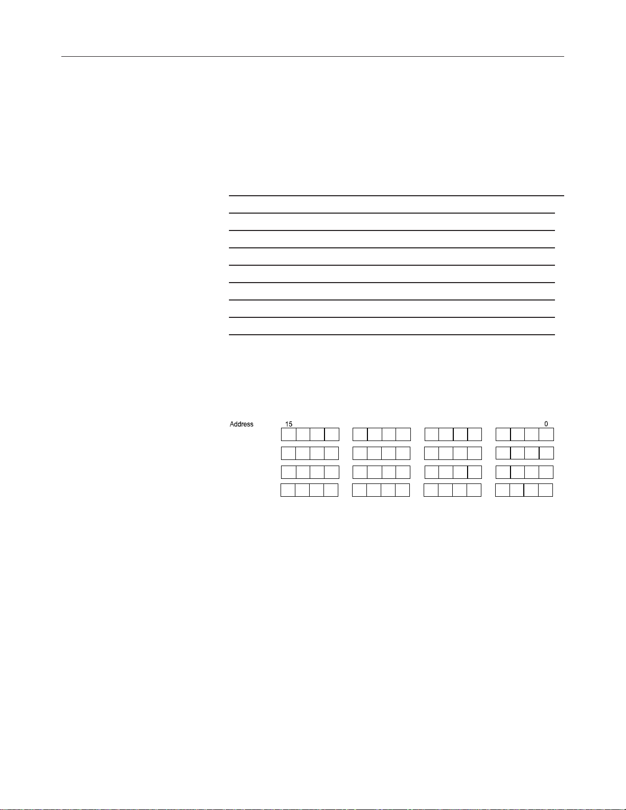
60 SLC 500™ 50 KHz Counter / Flowmeter Module
I
I
I
I
Input Registers - Channel
Data
The channel data consists of 4 words, the lower counter data value, the
rate data high value, the rate data low value and the channel status data.
Table A.1 - Data Word Addresses
CTR8 CTR4 Scale/Limit Value
I:e.0 to I:e.3 I:e.0 to I:e.3 0 Channel LSW, Rate Data High, Rate Data Low , S tatus Reg
I:e.4 to I:e.7 I:e.4 to I:e.7 1 Channel LSW, Rate Data High, Rate Data Low , S tatus Reg
I:e.8 to I:e.11 I:e.8 to I:e.11 2 Channel LSW , Rate Data High, Rate Data Low , Status Reg
I:e.12 to I:e.15 I:e.12 to I:e.15 3 Channel LSW, Rate Data High, Rate Data Low , Status Reg
I:e.16 to I:e.19 (n/a) 4 Channel LSW , Rate Data High, Rate Data Low , Status Reg
I:e.20 to I:e.23 (n/a) 5 Channel LSW , Rate Data High, Rate Data Low , Status Reg
I:e.24 to I:e.27 (n/a) 6 Channel LSW , Rate Data High, Rate Data Low , Status Reg
I:e.28 to I:e.31 (n/a) 7 Channel LSW , Rate Data High, Rate Data Low , Status Reg
Figure A.2 - Data Words
D a ta Wo rd s f o r F loatin g Poin t Ra te Mode
:e. w
:e. x
:e. y
:e. z
89
Counter LSW
Rate O utput High
Rate O utput Lo w
Status Output
Page 61
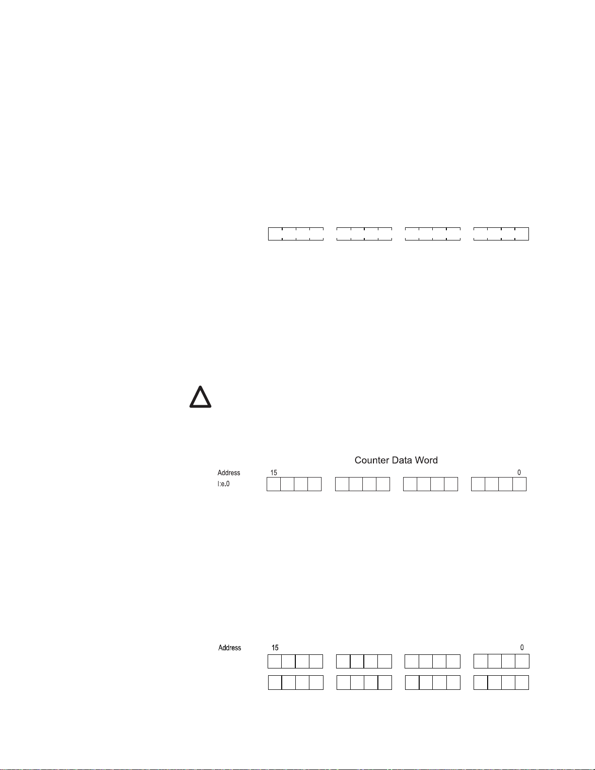
Setting the Rate Limit / R
I
I
Factor:
Input Registers:
Channel Data
Appendix A: Floating Point Rate Mode 61
The R Factor function is used to activate the floating point mode. Setting
the value to -1 activates this mode. Use Bit 15 in your channel
configuration word to save the R factor in the modules non-volatile
memory.
Figure A.3 - Rate Limit / R Factor Word
Address
O:e.z
15
9
Rate Limit / R Factor
0
8
Counter Output Register, Low word:
This output data register contains the lower word of the counter
accumulator. This register is a signed 16 bit word in binary 2’s
complement format and will allow count values up to ±32K. This word is
used in conjunction with the counter’s upper output word when in the
extended count mode. Bit 15 represents the sign for each word.
!
Note: Extended count mode is not a valid configuration when using the
floating point rate mode.
Figure 4.10 -Counter Low W ord
8
9
Counter Input Low
Rate Output Register words:
These two output data registers contain the rate value while operating in
floating point rate mode. The registers represent a 32 bit word in binary
2’s complement format and when combined form the 32 bit floating point
rate value.
Figure 4.12 -Counter Rate Word
Data Words for Floa ting Point Rate Mode
89
:e.x
:e.y
Rate Output High
Rate Output Low
Page 62

62 SLC 500™ 50 KHz Counter / Flowmeter Module
Module status:
Status remains the same as other modes. Information may be found in
Chapter 4.
Ladder Logic
In order to create the floating point value it necessary to join the high and
low rate data words. This is accomplished using the following ladder
logic.
Page 63

Appendix A: Floating Point Rate Mode 63
Page 64

64 SLC 500™ 50 KHz Counter / Flowmeter Module
Page 65

Getting Technical
Assistance
Declaration of
Conformity
If you need technical assistance, please review the information in Chapter
6, “T esting Your Module,” before calling your local distributor of Spectrum
Controls.
Note that your module contains electronic components which are
susceptible to damage from electrostatic discharge (ESD). An
electrostatic charge can accumulate on the surface of ordinary plastic
wrapping or cushioning material. In the unlikely event that the module
should need to be returned to Spectrum Controls, please ensure
that the unit is enclosed in approved ESD packaging (such as
static-shielding / metallized bag or black conductive container).
Spectrum Controls reserves the right to void the warranty on any unit that
is improperly packaged for shipment.
For further information or assistance, please contact your local distributor
or call Spectrum Controls Customer Satisfaction department at (425) 7469481 from 8:00 A.M. to 5:00 P.M. Pacific T ime.
A vailable upon request.
Page 66

The ENCOMPASS logo and SLC 500 are trademarks of Allen-Bradley Company, Inc. Copyright © 2000-2004, Spectrum Controls, Inc.
All rights reserved. Printed in U.S.A. Specifications subject to change without notice. Publication 0300181-05 Rev. G May 2004
U.S.A. Headquarters
Spectrum Controls Inc.
P.O. Box 5533
Bellevue, WA 98006
Fax: (425) 641-9473
Tel: (425) 746-9481
Web Site: http://www.spectrumcontrols.com
E-mail: spectrum@spectrumcontrols.com
 Loading...