

Page 1

16-Channel Universal Analog Input Module
(Catalog No. 140 AUI 040 00sc)
Installation Instructions
Document No. 0300180-02 Rev. B
Page 2

16-Channel Universal Analog Input Module
PREFACE
+ Note: Power, input and output (I/O) wiring must be in accordance with Class 1, Division 2 wiring methods
[Article 501-4 (b) of the National Electrical Code, NFPA 70] and in accordance with the authority having
jurisdiction.”
+ Note: Peripheral equipment must be suitable for the location in which it is used.
WARNING
ELECTROSTATICALLY SENSITIVE COMPONENTS
EXPLOSION HAZARD
Substitution of components may impair suitability for Class 1, Division 2.
WARNING
EXPLOSION HAZARD
Do not disconnect equipment unless power has been switched off or the area is known to be non
hazardous.
WARNING
This equipment is suitable for use in Class 1, Division 2, Groups A, B, C, and D or non-hazardous
locations only.
WARNING
EXPLOSION HAZARD
When in hazardous locations, turn off power before replacing or wiring modules.
Page 3

Quantum Series 140 AUI 040 00sc
Page 4

16-Channel Universal Analog Input Module
Contents
Chapter 1 - OVERVIEW 7
1.1 .................................................................................................................Inputs 8
1.2 ..................................................................................................................LEDs 9
1.3 ......................................................................................... Related Publications 9
Chapter 2 - MODULE SETUP FOR MODSOFT 11
2.1 ......................................................................................... General Information 11
2.2 ...................................................................... Installation of new run time files 11
2.3 ........................General information on data register usage and terminology: 12
2.4 ............................................................................. Zoom Sc reen Configuration 12
2.5 ...............................................................................4X Register Configuration 15
Chapter 3 - MODULE SETUP FOR CONCEPT 17
3.1 ......................................................................................... General Information 17
3.2 ...................................................................... Installation of new run time files 17
3.3 ........................General information on data register usage and terminology: 17
3.4 ............................................................. Concept I/O Map Module Parameters: 18
3.5 ................................................................. Spectrum I/O Configuration Utility 22
3.6 ............................................................................. SCIOCFG.EXE Installation: 22
Chapter 4 - MODULE CONFIGURA TION AND STA TUS 25
4.2 ..................................................... Module status information (Register 3x+8) 26
4.3 ............................................. Channel Status (Registers 3x+ 0 through 3x+7) 28
Chapter 5 - INST ALLATION 31
5.1 ..................................................................................................... Field Wiring 33
5.2 .............................................................................................. RTD Field wiring 33
5.3 ....................................................................... CJC Thermocouple Installation 34
Chapter 6 - APPLICATION NOTES 37
6.1 .................................................................................. General Application Tips 37
6.2 ....................................... Demultiplexing Channel Data - Autosequence Mode 37
6.3 ................... Using ladder to move data to a block of 16 consecutive registers 37
6.4 .........................................................................................Channel Update Rate 39
6.5 ...........................System Resolution and Accuracy - V oltage /Curr ent Modes 40
Chapter 7 - TROUBLESHOOTING 43
7.1 ......................................................................................... General Information 43
Chapter 8 - SPECIFICA TIONS 47
1.1 ...................................................................................Electrical Specifications 47
1.1A Table - Thermocouple Accuracy................................................................48
1.2 .......................................................................................System Specifications 50
1.3 ........................................................................... Environmental Specifications 50
Page 5

Quantum Series 140 AUI 040 00sc
Page 6

16-Channel Universal Analog Input Module
Chapter 1
OVERVIEW
The 140 AUI 040 00sc is a universal analog input module with 16 channels of input.
The module will accept voltage, current, resistance, thermocouple and RTD inputs. The voltage, current,
resistance and thermocouple inputs are divided into four groups of four inputs each. RTD inputs are divided
into 4 groups of 2 inputs each. Any combination of inputs may be used so long as they are configured on a
group basis. Each input has 12.5V of isolation from the other inputs. All inputs have 1000V DC isolation
channel-to-backplane.
This module has been designed for projects that include large quantities of analog and temperature inputs.
Process control and data acquisition applications for industries such as utilities, waste water, oil and gas, food
and beverage, and building automation are ideally suited for this module.
Input channels include over voltage circuit protection, over and under range detection and active notch
filtering. The modulde has open circuit detection for thermocouple inputs and both open and short circuit
detection for R TD inputs. The voltage mode of the module handles eight different voltage ranges and the
current mode handles three current ranges. Eight types of thermocouple inputs are supported. Sixteen types
of R TD inputs and four resistance input ranges are supported. You can configure the module to provide data in
one of four data formats. Set up of the module is very simple through the use of configuration and status
registers using Concept, Modsoft or Taylor programming software.
7
Page 7

Quantum Series 140 AUI 040 00sc
1.1 Inputs
The 16 Channels are separated into four groups of four. Each group can be configured for a different voltage,
current range, resistance, thermocouple and RTD range. The ranges available are as follows:
Current Ranges
• 4 to 20 mA, 0 to 20 mA, ±20mA
Voltage Ranges:
• ±0.05VDC, ±0.5VDC, ±2.0VDC, ±5VDC, ±10VDC, 0-10VDC, 0-5VDC, 1-5VDC
Resistance Ranges
• 150, 490, 980, 3000 ohm
Thermocouple Types
• Type J, K , T, E, R, S, B, N
RTD Types
• 100, 200, 500 and 1KΩ Pt Alpha 385,
100, 200, 500, and 1KΩ Pt Alpha 392,
100, 200, 500, and 1KΩ Nickel,
10Ω Copper 426,
120Ω Nickel 672, 604Ω Nickel/Iron 518.
The module can provide data to the PLC in the following formats:
• 12 bit (0 to 4095)
• signed 15 bit (-32768 to +32767)
• unsigned 16 bit (0 to 65535)
• DVM (0 to 10000)
Input Resistance 10MΩ nominal (V oltage)
250Ω nominal (Current)
8
Page 8

16-Channel Universal Analog Input Module
1.2 LEDs
The module has a front LED panel that includes 19 LEDs:
Ready LED - 1 Green LED indicates module’s self test has passed and is ready to communicate.
Active LED - 1 Green LED indicates BUS communication is established between the module and the rack.
Fault LED -1 Red LED indicates a module self test error, or fatal H/W error. A blink code will indicate the
type of self test error. Count the number of blinks before a pause to determine the error code in the table
below.
Blink # Fault
1 ROM CRC Error
2 EEPROM Error
3 RAM Error
4 Autocal Error
5 Watchdog T imer Error
6 CPU Error
7 DPM Error
Channel LED - 16 Green LEDs indicates the channel is enabled and a valid input signal level is present.
The LED is off if the channel is disabled. A blinking LED indicates that the channel has exceeded a range
limit.
1.3 Related Publications
• Modicon Modsoft Programmer User Manual. 890 USE 115 00
• Modicon TSX Quantum Automation Series Hardware Reference Guide. 840 USE 100 00
• IEEE Std 518- 1977, Guide for the Installation of Electrical Noise Inputs to Controllers from External Sources
• IEEE Std 142- 1982, Recommended Practice for Grounding of Industrial and Commercial Power Systems
• Noise Reduction T echniques in Electronic Systems, by Henry W. Ott; published by Wiley-Interscience of New York in
1976
9
Page 9

Quantum Series 140 AUI 040 00sc
10
Page 10

16-Channel Universal Analog Input Module
Chapter 2
MODULE SETUP FOR MODSOFT
2.1 General Information
Six steps must be performed in order to fully configure the Quantum system in preparation for using the AUI
040 00sc:
Step 1: Modsoft programming software must be updated so that the
140 AUI 040 00sc is recognized in the software (see Section 2.2).
Step 2: Select the appropriate slot location using the Modsoft I/O map. Choose the first 3x and 4x level registers to be
used in the system for the module’ s data, configuration and status information (see Section 2.3).
Step 3: Zoom screens for the module must be set to match application requirements (see Section 2.4).
Step 4: The 4x configuration register must be set to meet application requirements (see Section 4.1).
Step 5: Module status information is available to you. The various options must be understood and chosen to meet
your application requirements (see Section 4.2 and Section 4.3).
Step 6: Ladder rungs must be written to demultiplex the incoming 8 data registers to 16 user selected data registers (see
Section 6.3).
2.2 Installation of new run time files
If you are using the Modsoft programming software version 2.4 or 2.5, it is necessary to update the following
runtime files in order for Modsoft to recognize your module. Versions prior to 2.4 are not supported. Version
2.6 and newer already include these updates.
LMSFDT .SYS Zoom screens
GCNFTCOP .SYS I/O Map module definitions
QUANTUM.SYS Quantum help screens
This may be accomplished by first identifying the pathname where you have installed your Modsoft programming software and the drive letter of the floppy drive from which you intend to install. A typical pathname
assuming installation of the C: drive is as follows:
C:\MODSOFT
The new runtime files required to use all versions of this module are supplied on the 3.5 inch MSDOS formatted floppy disk titled:
“Quantum Runtime Files,” Spectrum Controls, Inc Part Number: 20500121-02
T o install these files, operate your PC in MSDOS mode, perform the following command:
C:>\COPY A:*.SYS C:\MODSOFT\RUNTIME
+ Note: This assumes you are installing from drive A: and that you have previously installed Modsoft in the
directory C:\MODSOFT. If not, you must make the appropriate substitutions.
11
Page 11

Quantum Series 140 AUI 040 00sc
2.3 General information on data register usage and terminology:
A total of nine 3x level and one 4x level registers are used by the 140 AUI 040 00sc. After you have completed the runtime file installation, you can go to the I/O Map screen and choose the 140 AUI 040 00sc by
selecting the desired slot, pressing <Shift + ?> which will display the modules available for configuration into
that slot. For module specific help, press <ALT + H>. After selecting the module, you must set the first 3x
and 4x level registers to be used. This will then automatically capture nine consecutive 3x level and one 4x
level register for use by the module. The architecture for this 16-channel module is as follows:
4x Configuration Word
3x + 0 Input Data Channel 1/9
3x + 1 Input Data Channel 2/10
3x + 2 Input Data Channel 3/11
3x + 3 Input Data Channel 4/12
3x + 4 Input Data Channel 5/13
3x + 5 Input Data Channel 6/14
3x + 6 Input Data Channel 7/15
3x + 7 Input Data Channel 8/16
The AUI 040 00sc multiplexes 16 channels of data into eight groups of two channels. Each group can be
selected through the 4x Configuration Word or can automatically sequence through all four groups of channels.
3x + 0 Input Data Channel 1/9 Group 2 Chn 5-8
3x + 1 Input Data Channel 2/10
3x + 2 Input Data Channel 3/11 Group 3 Chn 9-12
3x + 3 Input Data Channel 4/12 Group 4 Chn 13-16
3x + 4 Input Data Channel 5/13
3x + 5 Input Data Channel 6/14
3x + 6 Input Data Channel 7/15
3x + 7 Input Data Channel 8/16
Group 1 Chn 1-4
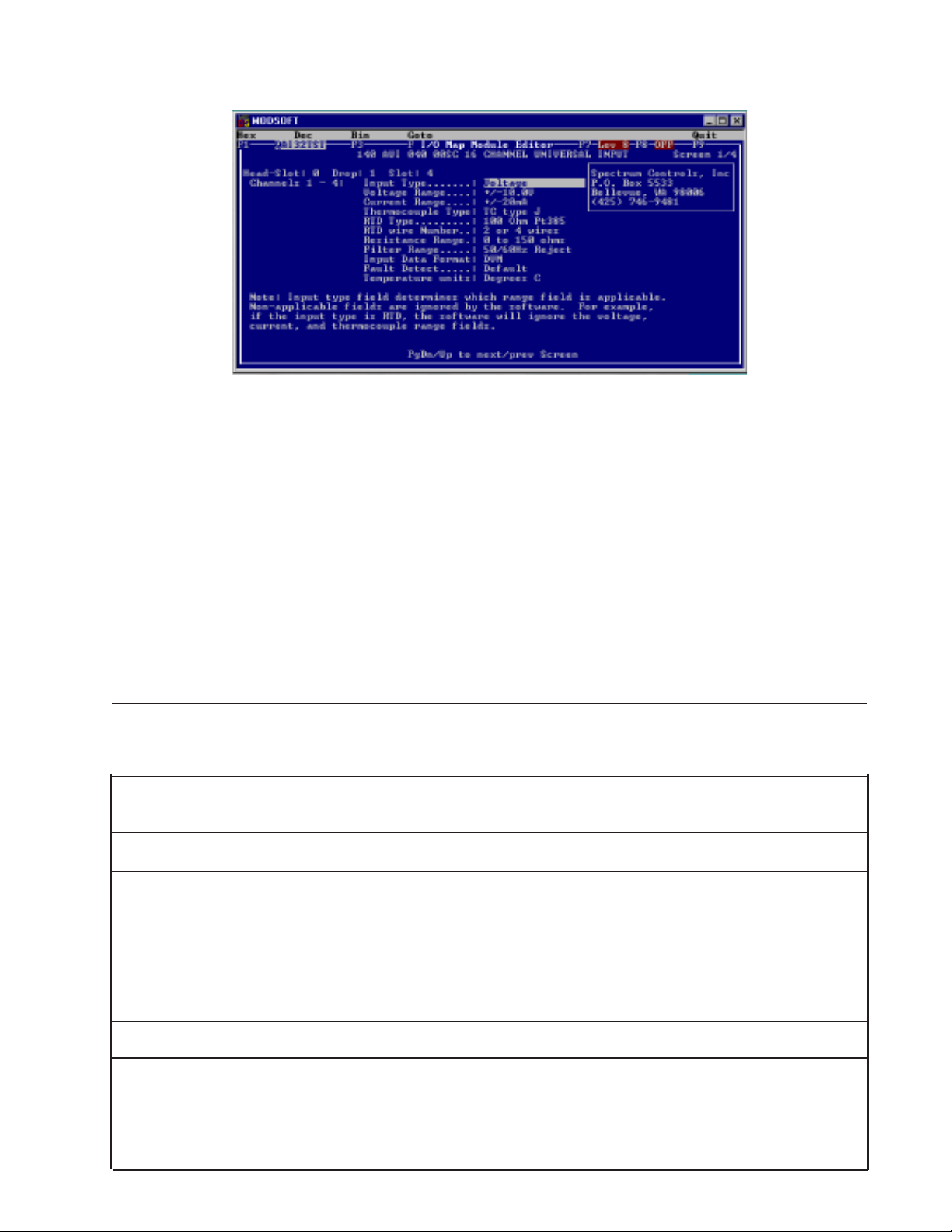
2.4 Zoom Screen Configuration
For Zoom Screen operation, please refer to Modicon’s Modsoft Programmer User Manual.
! Note: T o enter zoom screens from the I/O map menu, highlight the module entry and press the keys <AL T - Z>.
Most of the module setup will be done through the Modsoft zoom screens. The zoom screen setup establishes
the following parameters:
• Input Type
• Input Range
• Filter Frequency Selection
• Input Data Format
• Operational Mode
12
Page 12
16-Channel Universal Analog Input Module
Figure 2.1
Input T ype:
You have 5 input types to select from, one of the following input types may be selected for each of the four
groups of four channels:
Type: Voltage [default]
Current
Thermocouple
RTD
Resistance
Input Range:
Depending on the type of input selected , one of the following input ranges may be selected for each of the
four groups of four channels:
Type: Voltage
Bipolar Ranges (vdc) -0.05 to +0.05 -0.50 to +0.50 -2.0 to +2.0 -5.0 to +5.0 -10.0 to +10.0
Unipolar Ranges (vdc) 0 to +5.0 +1.0 to +5.0 0 to +10.0
Type: Current
Ranges (mA) -20.0 to +20.0 0 to +20.0 4.0 to 20.0
Type: Thermocouple T ype J, K, T , E, R, S, B, N
Type: RTD
Pt 385 RTD 100ohm RTD 200ohm RTD 500ohm RTD 1000ohm
Pt 392 RTD 100ohm RTD 200ohm RTD 500ohm RTD 1000ohm
Cu 426 RTD 10ohm
Ni 618 RTD 100ohm RTD 200ohm RTD 500ohm RTD 1000ohm
Ni 672 RTD 120ohm
Ni/Fe 518 RTD 604ohm
Type: RTD Cfg. 2/4 Wire 3 Wire
Type: Resistance 150ohm 490ohm 980ohm 3000ohm
13
Page 13

Quantum Series 140 AUI 040 00sc
Filter Frequency Selection:
The Analog-to-Digital Conversion performs a filter function on the input signal. One of the following filter
frequencies may be selected for each of the four groups of eight channels:
Rejection Type Filter Freq. Zoom Screen Name
50/60Hz Rejection 13.65Hz 3dB [default] Reject 50/60Hz
High Noise Rejection 7.80 3dB Reject 28Hz
Mid Range 209.6Hz 3dB Reject 800Hz
High Speed 1676.8Hz 3dB Reject 6.4kHz
Input data format:
One of the following data formats may be selected for each of the four groups of four channels:
Format: Digital V oltmeter [default]
12-bit Unsigned Format
16-bit Signed Format
16-bit Unsigned Format
! Note: The module’s format selection must be compatible with the register format selected in Modsoft.
Fault Detection:
One of the following detection formats may be selected for each of the four groups of four channels:
Format: Default [Max on over-range, min on under-range]
Max on Fault
Min on Fault
0 on Fault
T emperature Units:
One of the following unit formats may be selected for each of the four groups of four channels:
Format: Degrees Celsius [default]
Degrees Fahrenheit
Calibration rate:
The Quantum module performs an on board system calibration at power up. The system calibration corrects
for temperature drift of the Analog to Digital Convertor (ADC) and related circuitry. System calibration can
be performed periodically based on the calibration rate selected below. This can affect the update time for
the module. For installations where the ambient temperature surrounding the I/O rack can change relatively
quickly, the user might consider going to a more frequent calibration selection in order to improve the accuracy
of the reading being taken. The autocalibration schedule rate may be selected from the following:
Once at power up only [default]
Every 1 min
Every 10 min
Every 30 min
14
Page 14

16-Channel Universal Analog Input Module
Selecting an autocalibration schedule rate is an exercise in tradeoffs. Performing autocalibration more frequently may result in greater accuracy due to variations caused by environmental factors such as temperature.
This accuracy has a cost in the burden imposed by performing the calibration. The calibration time is a
function of the filter frequency . Calibration times are listed below. The system cannot update the channel
data while performing calibration. In addition, if multiple filter frequencies are selected, calibrations for each
frequency and the execution time is cumulative. The worst case calibration time is when all filter frequencies
are enabled (7.8, 13.6, 50/60 and 1677 Hz). The time is then the total for all four times listed below. Also,
note that the channel enables have no effect on the auto calibration feature. If a filter frequency is enabled via
the zoom screens, then the autocalibration is performed for the frequency.
Filter Freq. 16 Ch. Update Rate
7.8 Hz - 3db 1992 msec
13.6 Hz - 3bd 1168 msec
209.6 Hz - 3db 132 msec
1677 Hz - 3db 80 msec
2.5 4X Register Configuration
Refer to Chapter 4 for 4x register setting information.
15
Page 15

Quantum Series 140 AUI 040 00sc
16
Page 16

16-Channel Universal Analog Input Module
Chapter 3
MODULE SETUP FOR CONCEPT
3.1 General Information
Six steps must be performed in order to fully configure the Quantum system in preparation for using the AUI
040 00sc:
Step 1: Concept programming software (V ersion 2.1 or newer) must be updated so that the 140 AUI 040 00sc is recognized in the software (see Section 3.2).
Step 2: Select the appropriate slot location using the Concept I/O map editor . Choose the first 3x and 4x level registers to
be used in the system for the module’ s data, configuration and status information (see Section 3.3).
Step 3: Parameters for the module must be set to match application requirements (see Section 3.4).
Step 4: The 4x configuration register must be set to meet application requirements (see Section 4.1).
Step 5: Module status information is available to you. The various options must be understood and chosen to meet
your application requirements (see Section 4.2 and Section 4.3).
Step 6: Ladder rungs must be written to demultiplex the incoming 8 data registers to 16 user selected data registers (see
Section 6.3).
3.2 Installation of new run time files
The 140 AUI 040 00sc is manufactured by Spectrum Controls, Inc. Follow the Concept installation procedure for
outsourced modules. This requires the install disk provided with your module, which includes the following files
(assuming drive A:):
A:\CONCEPT\SPECTRUM.MDC - SpectrumI/O for Quantum Module Definition file.
A:\CONCEPT\SPECTRUM.HLP - Spectrum I/O for Quantum Help file.
To update the Concept database with a new Spectrum I/O module:
1. Insert the install disk into drive A:
2. Start the Concept Modconnect Tool (Modconf.exe).
3. Open the installation file “SPECTRUM.MDC”
4. Select the module to add or press the “Add All” button
5. Save the changes before exiting the Modconnect tool.
This will update the Concept database permanently unless you later undo the changes using the Modconnect
Tool, or perform a new Concept software install.
3.3 General information on data register usage and terminology:
A total of nine 3x level and one 4x level registers are used by the 140 AUI 040 00sc. After you have completed adding the modules to the Concept database using the Modconnect tool, you can add a module to a drop
by using the Concept Configurator as follows:
1. Open an existing or create a new project.
2. Select the Configurator from the project pulldown menu.
3. Select Configure then select the I/O map menu.
4. On the I/O map menu, press the EDIT button for the appropriate drop.
5. Push the button in the module select column for the appropriate slot.
6. Select the desired module from the list of available modules.
7. Enter the starting 3x register address (InRef). Nine registers are automatically allocated.
8. Enter the starting 4x register address (OutRef). One register is allocated.
9. Press the parameters button. (Refer to the SC Config Utility - Section 3.5)
10. Verify register values are correct for the desired behavior.
17
Page 17

Quantum Series 140 AUI 040 00sc
The register data formats are discussed in the following section.
4x Configuration Word
3x + 0 Input Data Channel 1/9
3x + 1 Input Data Channel 2/10
3x + 2 Input Data Channel 3/11
3x + 3 Input Data Channel 4/12
3x + 4 Input Data Channel 5/13
3x + 5 Input Data Channel 6/14
3x + 6 Input Data Channel 7/15
3x + 7 Input Data Channel 8/16
The AUI 040 00sc multiplexes 16 channels of data into four groups of four channels. Each group can be
selected through the 4x Configuration Word or can automatically sequence through all four groups of channels.
Group 1 Chn 1-4
3x + 0 Input Data Channel 1/9 Group 2 Chn 5-8
3x + 1 Input Data Channel 2/10
3x + 2 Input Data Channel 3/11 Group 3 Chn 9-12
3x + 3 Input Data Channel 4/12 Group 4 Chn 13-16
3x + 4 Input Data Channel 5/13
3x + 5 Input Data Channel 6/14
3x + 6 Input Data Channel 7/15
3x + 7 Input Data Channel 8/16
3.4 Concept I/O Map Module Parameters:
Concept programming software does not implement zoom screens for ModConnect partner modules and
allows only direct editing of the I/O configuration parameters using 16 bit hex values. Spectrum Controls has
provided a software utility to simplify the configuration process. Refer to Section 3.5 for details.
From the Concept main screen, highlight the “configure” pull-down menu and choose “I/O Map.” In the I/O
Map screen insert the number for the correct “drop” and choose “edit.” Select the Spectrum Controls catalog
number that you wish to use from the list presented. When the screen appears, representing the Spectrum
module you have selected, highlight the parameters button. You must insert Hex values for registers #1, 2 and
3 to fully configure the module. The format that will instruct you on how to create the I/O map parameters is
listed below. For each of the parameters listed we have provided a detailed explanation in Chapter 2. Please
refer to detailed functional descriptions in the MODSOFT zoom screen discussions (Section 2.4). You must
go through each of the options below to establish the correct pattern for each of these three registers. Once
you have the bit pattern, then you can convert each to a four-digit Hex value that is used in the parameters
screen.
Configuration Register 1
Group 1 Group 2 Group 3 Group 4
Ch. 1-4 Ch. 5-8 Ch. 9-12 Ch. 13-16
Zoom +10 Zoom +12 Zoom +14 Zoom +16
18
Page 18

16-Channel Universal Analog Input Module
1 2 3 4 5 6 7 8 910111213141516
Input Type
Voltage Range
Current Range
Thermocouple Type
RTD Type
RTD Wire #
Bit Selection Pattern: Input Type for Group 1, 2, 3, 4 - Zoom Register 1,3,5,7
Bit 14 Bit 15 Bit 16 Description
0 0 0 Voltage (Default)
0 0 1 Current
0 1 0 Thermocouple
011RTD
1 0 0 Resistance
1 0 1 CJC
1 1 0 Not valid
1 1 1 Not valid
Bit Selection Pattern: Volt age Range for Group 1, 2, 3, 4 - Zoom Register 1,3,5,7
Bit 11 Bit 12 Bit 13 Description
0 0 0 -0.05 to +0.05vDC
0 0 1 -0.50 to +0.50vDC
0 1 0 -2.00 to +2.00vDC
0 1 1 -5.00 to +5.00vDC
1 0 0 -10.0 to +10.0vDC *(default)
1 0 1 0 to +5.0vDC
1 1 0 1 to +5.0vDC
1 1 1 0 to +10.0vDC
Bit Selection Pattern: Current Range for Group 1, 2, 3, 4 - Zoom Register 1,3,5,7
Bit 9 Bit 10 Description
0 0 -20 to +20mA
0 1 0 to +20mA
1 0 4 to +20mA
1 1 N/A
Bit Selection Pattern: Thermocouple Type for Group 1, 2, 3, 4 - Zoom Register 1,3,5,7
Bit 6 Bit 7 Bit 8 Description
0 0 0 Thermocouple type J
0 0 1 Thermocouple type K
0 1 0 Thermocouple type T
0 1 1 Thermocouple type E
1 0 0 Thermocouple type R
1 0 1 Thermocouple type S
1 1 0 Thermocouple type B
1 1 1 Thermocouple type N
19
Page 19

Quantum Series 140 AUI 040 00sc
Bit Selection Pattern: Volt age Range for Group 1, 2, 3, 4 - Zoom Register 1,3,5,7
Bit 2 Bit 3 Bit 4 Bit 5 Description
0000RTD 100 ohm Pt 385
0001RTD 200 ohm Pt 385
0010RTD 500 ohm Pt 385
0011RTD 1000 ohm Pt 385
0100RTD 100 ohm Pt 392
0101RTD 200 ohm Pt 392
0110RTD 500 ohm Pt 392
0111RTD 1000 ohm Pt 392
1000RTD 10 ohm Cu 426
1001RTD 100 ohm Ni 618
1010RTD 200 ohm Ni 618
1011RTD 500 ohm Ni 618
1100RTD 1000 ohm Ni 618
1101RTD 120 ohm Ni 672
1110RTD 604 ohm Ni/Fe 518
1 1 1 1 Not used
Bit Selection Pattern: R TD / Resistance Wires for Group 1, 2, 3, 4 - Zoom Register 1,3,5,7
Bit 1 Description
0 2 or 4 Wire
1 3 W ire
Configuration Register 2
Group 1 Group 2 Group 3 Group 4
Ch. 1-4 Ch. 5-8 Ch. 9-12 Ch. 13-16
Zoom +11 Zoom +15 Zoom +17 Zoom +16
1 2 3 4 5 6 7 8 910111213141516
Resistance Range
Filter Frequency
Input Data Format
Fault Detection
Temperature Units
Not Used
Bit Selection Pattern: Input Resistance Range for Group 1, 2, 3, 4 - Zoom Register 2,4,6,8
Bit 15 Bit 16 Description
0 0 150ohm (Default)
0 1 490ohm
1 0 980ohm
1 1 3000ohm
Bit Selection Pattern: Input Filter Frequency for Group 1, 2, 3, 4 - Zoom Register 2,4,6,8
Bit 13 Bit 14 Description
0 0 50/60Hz Rejection 13.65Hz 3db (Default)
0 1 High Noise Rejection 7.8Hz 3db
1 0 Mid Range Noise Rejection 209.6Hz 3db
1 1 High Speed 1676.8Hz 3db
20
Page 20

16-Channel Universal Analog Input Module
Bit Selection Pattern: Input Data Format for Group 1, 2, 3, 4 - Zoom Register 2,4,6,8
Bit 11 Bit 12 Description
0 0 16 bit unsigned integer
0 1 DVM (Default)
1 0 12 bit unsigned integer
1 1 15 bit signed integer
Bit Selection Pattern: Fault Detect for Group 1, 2, 3, 4 - Zoom Register 2,4,6,8
Bit 9 Bit 10 Description
0 0 Disabled
0 1 Max. on Fault (Default)
1 0 Mi.n. on Fault
1 1 0 on Fault
Bit Selection Pattern: T emperature Units for Group 1, 2, 3, 4 - Zoom Register 2,4,6,8
Bit 8 Description
0 Degrees Celcius (Default)
1 Degrees Farenheight
Once you have established the correct bit pattern for each of these three registers, you can convert each to a
four digit Hex value that is used in the parameters screen. A Hex conversion table follows:
0000=0
0001=1
0010=2
0011=3
0100=4
0101=5
0110=6
0111=7
1000=8
1001=9
1010=A
1011=B
1100=C
1101=D
1110=E
1111=F
21
Page 21

Quantum Series 140 AUI 040 00sc
3.5 Spectrum I/O Configuration Utility
“SCIOCFG.EXE” is a utility provided on the install disk under the typical pathname
“A:\CONCEPT\SCIOCFG.EXE”. “SCIOCFG.EXE” is intended to help users configure Spectrum I/O when
using Concept. This tool is intended to make the configuration of I/O modules supplied by Spectrum Controls
easy to accomplish when using Concept.
Version 2.1 of the Concept programming software introduced the tool for importing ModConnect module
definition files into the Concept database. This allows Concept users to configure ModConnect I/O such as
the 140 AUI 040 00sc. However, Concept V2.1 does not provide a means for ModConnect I/O developers to
design their own I/O configuration menus. Instead, Concept provides a generic interface where the user must
enter configuration parameters in hexadecimal values. The Spectrum I/O modules are designed to be feature
rich with an efficient use of registers. This requires the user to be intimately aware of the initialization parameters structure in order to perform simple I/O configuration changes. Simply stated, users can calculate the
correct hexadecimal values for the configuration parameters but it is a tedious task, SCIOCFG is designed to
relieve the user of this burden.
SCIOCFG presents the user with user friendly selection lists using standard Windows interfaces. SCIOCFG
also automatically constrains all parameters to legal values during the data entry process.
SCIOCFG may be run in one of two modes, stand alone mode, or synchronous mode. In the stand alone
mode, the user configures the data for a given module as desired. SCIOCFG then presents the parameters in
hexadecimal values so the user may then manually transfer this data to Concept at a later time.
In the synchronous mode, SCIOCFG runs in the background waiting for the user to select the generic I/O
parameters configuration menu for any one of the modules supported. When this occurs, SCIOCFG reads the
data from the Concept generic I/O parameter configuration menu, and activates the appropriate I/O parameter
configuration menu. When the user clicks on the SCIOCFG OK button, the new data is sent back to Concept.
3.6 SCIOCFG.EXE Installation:
SCIOCFG.EXE is a 32-bit W indows program requiring Windows 95 or newer. Installation of SCIOCFG.EXE
is simple. Copy the SCIOCFG.EXE file from the installation disk to the desired directory . Then you may add
a shortcut to the windows desktop or add the program to the windows taskbar using standard windows
techniques.
e.g. From a DOS window:
C:\>MD C:\SCIOCFG
C:\> COPY A:\CONCEPT\SCIOCFG.EXE C:\SCIOCFG
To add a shortcut:
1. Place the mouse cursor on an open area of the windows desktop.
2 . Click the right mouse button.
3 . Select the “New” option.
4. Select the “Shortcut” option.
5. Enter the full install pathname. E.G. C:\SCIOCFG\SCIOCFG.EXE
+ Note :The user may optionally configure SCIOCFG to always run in either the stand alone mode or the
synchronous mode. T o do this, place a space in one of the following strings immediately after the full
pathname:
NO_SYNC
SYNC_WITH_CONCEPT
E.G. C:\SCIOCFG\SCIOCFG.EXE SYNC_WITH_CONCEPT
22
Page 22

16-Channel Universal Analog Input Module
6 . Name as desired.
7. Activate the “Finish” button.
T o add to Windows Programs Selections or a Folder:
1. Click and hold the left mouse button on the taskbar start button.
2. Select “Settings, “Taskbar” and release the mouse button.
3 . Select the “Start Menu Programs” tab index.
4. Press the Add button.
5 . Choose an existing folder (perhaps the Concept programming folder) or create a new folder to hold SCIOCFG.EXE.
6 . Add SCIOCFG.EXE as described for adding shortcuts step 5.
SCIOCFG EXE is ready to run.
The SCIOCFG.EXE should be running as a background task, whenever Concept software is being used to
change the configuration registers of the 140 AUI 040 00sc series of modules. Start SCIOCFG.EXE by
double clicking on the SCIOCFG.EXE icon, then start Concept software.
Figure 3.1 SC Config Utility Screen
23
Page 23

Quantum Series 140 AUI 040 00sc
24
Page 24

16-Channel Universal Analog Input Module
Chapter 4
MODULE CONFIGURA TION AND ST ATUS
The 140 AUI 040 00sc uses a total of nine 3x level and one 4x level registers. After Modsoft (Section 2.3)
or Concept (Section 3.3) software is installed, additional configuration and status registers are set as follows:
4.1 Configuration word format (Register 4x)
1 2 3 4 5 6 7 8 910111213141516
Channel 1/2 Disable
Channel 3/4 Disable
Channel 5/6 Disable
Channel 7/8 Disable
Channel 9/10 Disable
Channel 11/12 Disable
Channel 13/14 Disable
Channel 15/16 Disable
Bank Select
Sequence Mode
Data Mode
Calibration Rate
Lead Measurement
4x Lead Resistance Measurement: Bits 1-2
This applies only when the module interfaces 3 wire RTDs. These two bits determine how frequently the
module will measure the RTD lead wire resistance. It is unlikely lead resistance will change much over time.
Reading the lead resistance effectively doubles the update time for RTD measurements
Bit 1 Bit 2 Mode
0 0 Equal to calibration rate
0 1 On power up only
1 0 Every 3-wire RTD reading
1 1 Not Allowed
4x Calibration Mode: Bits 3-4
These two bits are used to select a desired calibration interval.
Bit 3 Bit 4 Mode
0 0 On power up only
0 1 Every Minute
1 0 Every 10 Minutes
1 1 Every 30 Minutes
4x Data Input Mode: Bits 5-6
The module continuously outputs a group of eight registers worth of data. The data for a given group can be
paged between two modes. These are the standard channel input data and channel status data.
Bit 5 Bit 6 Input Modes
0 0 Input Data
0 1 Status Data 1
1 0 Not Used
1 1 Status Data 2
25
Page 25

Quantum Series 140 AUI 040 00sc
4x Autosequence Disable: Bit 7
When in Auto Sequence Mode, the module ignores the channel bank select in the 4X-configuration word, and
instead sequences through both banks automatically . The values in the eight data registers belong to the bank
identified in the status word bank ID (3X+8 bit 1). The user must set aside 16 registers as a permanent image
of the channel data. During run time, the ladder need only determine the current bank for the eight data
registers (3x+0 through xx+7) in order to determine where the data should be copied into the 16-channel
register image.
When in Manual Sequence Mode (Bit 7 = 0) the module reads only the eight channels identified by the Bank
Select Bits.
When autosequence is disabled, the user must manually increment the group select in the configuration word
and the module sends back only the data requested.
Sample ladder logic for both techniques is provided in section 6.3.
4x Bank Select: Bit 8
Bit 8 is used to select the desired Bank of channels. Bank 0 is defined as the first eight input channels. I.e.
configuration groups 1 and 2. And bank 1 is defined as the second 8 input channels. I.e. configuration groups
3 and 4. The bank select bit is used for individual bank selection when the Manual Sequence mode is used.
4x Group Channel Disable: Bits 9-16
These bits are used to enable or disable channel pairs. A “0” enables the group, a “1” disables the group.
Disabling groups of channels improves system response time.
Bit 16: Channels 1-2
Bit 15: Channels 3-4
Bit 14: Channels 5-6
Bit 13: Channels 7-8
Bit 12: Channels 9-10
Bit 11: Channels 11-12
Bit 10: Channels 13-14
Bit 9: Channels 15-16
4.2 Module status information (Register 3x+8)
The information provided in this register is generic information about this module. Bits 1-8 and 10 provide
error status information. Bits 13-16 indicate what information is present in the current inputs registers.
1 2 3 4 5 6 7 8 910111213141516
Range Error
Configuration Error
Broken Input
CJC Error
CPU Error
Watchdog Error
RAM Failure
Bank Select Echo
Sequence Mode Error
Data Mode Echo
ROM Failure
EEPROM Failure
Not Used
26
Page 26

16-Channel Universal Analog Input Module
3x+8 Not Used: Bits 1, 2
3x+8 EEPROM Error: Bit 3
An onboard re-writeable memory error has occured. Contact your technical support representative.
3x+8 ROM Failure: Bit 4
A read only memory error has occured. Contact your technical support representative.
3x+8 Data Mode Echo: Bits 6,5
The Module continuously outputs a bank of eight registers worth of data. The data for a given bank can be
paged between 2 modes. These are the standard channel input data and channel status data.
3x+8 Sequence Mode Echo: Bits 7
When in Auto Sequence Mode, the module ignores the channel bank select in the 4X-configuration word, and
instead sequences through both banks automatically . The values in the eight data registers belong to the bank
identified in the status word bank ID (3X+8 bit 1). The user must set aside 16 registers as a permanent image
of the channel data. During run time, the ladder need only determine the current bank for the eight data
registers (3x+0 through xx+7) in order to determine where the data should be copied into the 16-channel
register image.
When in Manual Sequence Mode the module reads only the eight channels identified by the Bank Select Bits.
3x+8 Bank Select Echo: Bits 8
This bit is used to show the selected bank channels. This will indicate individual bank selection when the Auto
Sequence mode in not used. The bank select is used for multiplexing out the Modules input data and status
data. The channel Status Mode disables the normal data input mode and reports the status on the selected
bank of 8 channels. The channel status bits echo back the selected input range data format and error status.
3x+8 RAM Failure: Bits 9
A random access memory error has occured. Contact your technical support representative.
3x+8 Watchdog Error: Bits 10
A watchdog timeout error occured. Contact your technical support representative.
3x+8 CPU Error: Bits 11
A central processing unit error has occured. Contact your technical support representative.
3x+8 CJC Error: Bits 12
A cold junction compensation error has occured. Check your onboard CJC sensor connections. These are
found on the terminal block.
3x+8 Broken Input Mode: Bits 13
Check your input connections for continuity .
3x+8 Configuration Error: Bit 14
An illegal configuration was attempted. When this occurs configuration will not be accepted by the module
and this flag will be set. By using 4x register bits 1 and 2 to set the module to “status” individual channels
flags can be checked to determine which channel or group is incorrect.
3x+8 Out of Range Error: Bits 15-16
These two bits indicate that an over or under range condition exists on at least one channel within the group.
Bits 1-2 correspond to two groups of eight channels each. When an Out of Range Flag is set, the Channel
Status mode (see Section 4.3) can be enabled to report which channel is out of range.
+ Note: An over range error indicates that a channel input is a value greater than or equal to the maximum for the range selected for
that channel group. An under range error indicates that a channel input is a value less than or equal to the minimum for the selected
range.
27
Page 27

Quantum Series 140 AUI 040 00sc
4.3 Channel Status (Registers 3x+ 0 through 3x+7)
(Registers 3x+ 0 through 3x+7) Status Mode 1:
1 2 3 4 5 6 7 8 910111213141516
3x+0 . . . 7 RTD Wire Number Echo: Bit 1
3x+0 . . . 7 RTD T ype Echo: Bits 2-5
3x+0 . . . 7 Thermocouple Range Echo: Bits 6-8
3x+0 . . . 7 Current Range Echo: Bits 9-10
3x+0 . . . 7 V oltage Range Echo: Bit s 1 1-13
3x+0 . . . 7 Input T ype Echo: Bits 14-16
Input Type Echo
Voltage Range Echo
Current Range Echo
Thermocouple Range Echo
RTD Type Echo
RTD Wire Number Echo
(Registers 3x+ 0 through 3x+7) Status Mode 2:
1 2 3 4 5 6 7 8 910111213141516
Resistance Range Echo
Filter Echo
Format Echo
Fault Detect Echo
Temperature Units Echo
Calibration Error
Configuration Error
Over Range
Under Range
Broken Input
CJC Error
Bank Number
3x+0 . . . 7 Bank Number: Bit 1
3x+0 . . . 7 CJC Error Echo: Bit 2
3x+0 . . . 7 Broken Input Echo: Bit 3
3x+0 . . . 7 Under Range Flag: Bit 4
This is a nonfatal under range flag. The bit is set to “1” when an input value is read within one count of the
minimum range value. When the input value is within normal limits the flag is automatically reset to “0.”
28
Page 28

16-Channel Universal Analog Input Module
3x+0 . . . 7 Over Range Flag: Bit 5
This is a nonfatal over range flag. The bit is set to “1” when an input value is read within one count of the
maximum range value. When the input value is within normal limits the flag is automatically reset to “0.”
3x+0 . . . 7 Configuration Error Flag: Bit 6
The calibration error flag is a fatal error. When the flag is set to “1” there is a configuration mismatch.
Configuration errors include any illegal configuration, such the selection of an unsupported format or filter
option, or configurations that must be the same for all channels within a group of channels.
3x+0 . . . 7 Calibration Error Flag: Bit 7
The calibration error flag is a fatal error. When the flag is set to “1” the ADC cannot calibrate within specifications.
3x+0 . . . 7 Temperature Units Echo: Bit 8
3x+0 . . . 7 Fault Detect Echo: Bits 9-10
3x+0 . . . 7 Format Echo: Bit 11-12
3x+0 . . . 7 Filter Echo: Bit 13-14
3x+0 . . . 7 Resistance Range Echo: Bit 15-16
RTD Fault Detection
The module can detect both RTD open circuits and shorts. This works as follows:
· Open positive excitation. The S/W will read positive full scale. This will be flagged as a bad input.
Reading will default to the full-scale value for the range selected. Note that S/W can detect an overrange which is not an open input.
· Open negative excitation. Reading will be 0. This will cause the reading to be flagged as a bad input.
V alue read will be negative full scale for the range selected.
· Open high signal. The module switches in the reference voltage prior to reading the RTD voltage. This
charges the filter capacitor downstream of the input multiplexer . If the input is open, This capacitance
will charge the filter capacitor upstream of the multiplexer input. This will cause the reading to eventually go to positive full scale and will be flagged as a bad input as it is when ther is an open positive
excitation. Note that this capacitive charging process may take several updates. This method is not
designed to instantly flag an open wire, but to ensure it will eventually “float” high enough to be an
obvious fault. Because of input range limitations, this method does not apply to the 3000 ohm resistance range or the 1000 ohm RTD ranges.
· Open low signal. If this wire opens, it will cause the input voltage read to float. If the input voltage
drifts too high or too low, a fault will be detected. Unlike the open hi signal, there is no technique
implemented to detect this type of fault.
29
Page 29

Chapter 5
INST ALLATION
16-Channel Universal Analog Input Module
+ Note: When field wiring the I/O modules, the maximum wire size that should be used is 1-14 AWG or 2-16 AWG; the
minimum size is 20 AWG.
+ Note: The field wiring terminal block (Modicon # 140 XTS 002 00) or the 140 CFA040 00 40 pin Cablefast
Terminal block must be ordered separately. (The terminal block includes the removable door label.)
+ Note: Power, input and output (I/O) wiring must be in accordance with Class 1, Division 2 wiring methods [Article
501-4 (b) of the National Electrical Code, NFPA 70] and in accordance with the authority having jurisdiction.”
+ Note: Peripheral equipment must be suitable for the location in which it is used.
31
Page 30

Quantum Series 140 AUI 040 00sc
WARNING
ELECTROSTATICALLY SENSITIVE COMPONENTS
EXPLOSION HAZARD
Substitution of components may impair suitability for Class 1, Division 2.
WARNING
EXPLOSION HAZARD
Do not disconnect equipment unless power has been switched off or the area is known to be non hazardous.
WARNING
This equipment is suitable for use in Class 1, Division 2, Groups A, B, C, and D or non-hazardous locations
only.
WARNING
EXPLOSION HAZARD
When in hazardous locations, turn off power before replacing or wiring modules.
Before installing the module, you should:
• Configure all of the appropriate zoom screen, configuration and other necessary set up according to Chapters 2 and 3.
• Field wire the module’s terminal block for your application.
For field wiring, use shielded, twisted-pair cable (such as Belden 9418 for voltage and current applications),
and ground each cable’s shield wire at one end only. At the opposite end of each cable, tape the exposed
shield wire to insulate it from electrical contact. A good shield wire ground is a rack assembly mounting bolt
or stud.
32
Page 31

16-Channel Universal Analog Input Module
5.1 Field Wiring
+ Note: In the process of wiring the modules, route all signal wires as far as possible from potential sources
of electrical noise, such as motors, transformers, etc., (especially ac devices). As a general rule, allow 15.2
cm (6 in) of separation for every 120V of power. Signal wires must never share the same conduit with ac
wiring. Also, when you must route signal wires past ac wiring, do so at right angles.
Figure 5.1 - Field Wiring - Voltage, Current, Thermocouple Inputs
Group Signal Name Pin # Signal Name Group
CJC 1 HI ( + ) 21 1 IN HI ( + ) 1
CJC 1 LO ( - ) 43 1 IN LO ( - ) 1
1 2 IN HI ( + ) 65 3 IN HI ( + ) 1
1 2 IN LO ( - ) 87 3 IN LO ( - ) 1
1 4 IN HI ( + ) 10 9 5 IN HI ( + ) 2
1 4 IN LO ( - ) 12 11 5 IN LO ( - ) 2
2 6 IN HI ( + ) 14 13 7 IN HI ( + ) 2
2 6 IN LO ( - ) 16 15 7 IN LO ( - ) 2
2 8 IN HI ( + ) 18 17 SHIELD 1
2 8 IN LO ( - ) 20 19 SHIELD 2
SHIELD 3 22 21 9 IN HI ( + ) 3
SHIELD 4 24 23 9 IN LO ( - ) 3
3 10 IN HI ( + ) 26 25 11 IN HI ( + ) 3
3 10 IN LO ( - ) 28 27 11 IN LO ( - ) 3
3 12 IN HI ( + ) 30 29 13 IN HI ( + ) 4
3 12 IN LO ( - ) 32 31 13 IN LO ( - ) 4
4 14 IN HI ( + ) 34 33 15 IN HI ( + ) 4
4 14 IN LO ( - ) 36 35 15 IN LO ( - ) 4
4 16 IN HI ( + ) 38 37 CJC 2 HI ( + )
4 16 IN LO ( - ) 40 39 CJC 2 LO ( - )
5.2 RTD Field wiring
RTDs may be wired using 2/4 wire or 3 wire configurations.
Figure 5.2 - Field Wiring - RTD Inputs
Group RTD Signal Pin # RTD SIGNAL Group
21EXCIT 1 Hi 1
43EXCIT 1 Lo 1
1 RTD 1 IN ( + ) 65EXCIT 2 Hi 1
1 RTD 1 IN ( - ) 87EXCIT 2 Lo 1
1 RTD 2 IN ( + )10 9 EXCIT 3 Hi 2
1 RTD 2 IN ( - ) 12 11 EXCIT 3 Lo 2
2 RTD 3 IN ( + )14 13 EXCIT 4 Hi 2
2 RTD 3 IN ( - ) 16 15 EXCIT 4 Lo 2
2 RTD 4 IN ( + )18 17
2 RTD 4 IN ( - ) 20 19
22 21 EXCIT 5 Hi 3
24 23 EXCIT 5 Lo 3
3 RTD 5 IN ( + )26 25 EXCIT 6 Hi 3
3 RTD 5 IN ( - ) 28 27 EXCIT 6 Lo 3
3 RTD 6 IN ( + )30 29 EXCIT 7 Hi 4
3 RTD 6 IN ( - ) 32 31 EXCIT 7 Lo 4
4 RTD 7 IN ( + )34 33 EXCIT 8 Hi 4
4 RTD 7 IN ( - ) 36 35 EXCIT 8 Lo 4
4 RTD 8 IN ( + )38 37
4 RTD 8 IN ( - ) 40 39
33
Page 32

Quantum Series 140 AUI 040 00sc
5.3 CJC Thermocouple Installation
When using thermocouples it is necessary to install the supplied Cold Junction Compensation thermocouples to
meet temperature accuracy specification. There are two CJC sensors, on located on the top of the terminal
block, the second located at the bottom of the terminal block. The CJC sensors are premounted on a small
circuit board to ease installation. To install the sensors unscrew terminal pairs 2/4 and 37/39 and slide the CJC
sensors under the screws. Tighten the screws to no more than 10 lbs. in. of torque.
Group Signal Name Pin # Signal Name Group
Insert CJC
#1 here.
CJC 1 HI ( + ) 21 1 IN HI ( + ) 1
CJC 1 LO ( - ) 43 1 IN LO ( - ) 1
1 2 IN HI ( + ) 65 3 IN HI ( + ) 1
1 2 IN LO ( - ) 87 3 IN LO ( - ) 1
1 4 IN HI ( + ) 10 9 5 IN HI ( + ) 2
1 4 IN LO ( - ) 12 11 5 IN LO ( - ) 2
2 6 IN HI ( + ) 14 13 7 IN HI ( + ) 2
2 6 IN LO ( - ) 16 15 7 IN LO ( - ) 2
2 8 IN HI ( + ) 18 17 SHIELD 1
2 8 IN LO ( - ) 20 19 SHIELD 2
SHIELD 3 22 21 9 IN HI ( + ) 3
SHIELD 4 24 23 9 IN LO ( - ) 3
3 10 IN HI ( + ) 26 25 11 IN HI ( + ) 3
3 10 IN LO ( - ) 28 27 11 IN LO ( - ) 3
3 12 IN HI ( + ) 30 29 13 IN HI ( + ) 4
3 12 IN LO ( - ) 32 31 13 IN LO ( - ) 4
4 14 IN HI ( + ) 34 33 15 IN HI ( + ) 4
4 14 IN LO ( - ) 36 35 15 IN LO ( - ) 4
4 16 IN HI ( + ) 38 37 CJC 2 HI ( + )
4 16 IN LO ( - ) 40 39 CJC 2 LO ( - )
Insert CJC
#2 here.
34
Page 33

16-Channel Universal Analog Input Module
35
Page 34

Quantum Series 140 AUI 040 00sc
36
Page 35

16-Channel Universal Analog Input Module
Chapter 6
APPLICA TION NOTES
6. 1 General Application Tips
The following is a list of do’ s and don’ts that should be observed in your applications.
• Select the appropriate 140 AUI 040 00sc from the I/O map selection screen.
• Configure the module using your programming software, make appropriate use of Configuration and Status registers as
outlined in Chapters 2 through 4.
• Ensure correct units of measure are selected for data type.
• Use the lowest filter frequency setting possible for your application, this ensures the most stable and accurate
readings.
• Configure the 4x Register.
• Check that the Green Ready LED is lit when the module is powered up and has completed its self test.
• Check that the Green Active LED is lit when data is being transferred to the Quantum CPU.
6.2 Demultiplexing Channel Data - Autosequence Mode
The autosequence mode of operation is intended to simplify the demultiplexing of channel data from the eight
input registers into storage for the 16 channels. The autosequence mode is enabled under the following conditions:
• Input Mode = Data Mode (Configuration W ord Bits 5 & 6 = 0)
In the autosequence mode, the group select bits in the configuration word are ignored. Instead, the module
samples channel data in groups of eight (8), presents the data to the PLC and then scans the next group
automatically. The ladder logic then reads the status word to determine which data is being presented and
copies the data to the appropriate storage locations for those channels.
The module update rate is determined by the number of channels enabled and the filter frequencies selected.
For example, if all 16 channels are enabled and the filter frequency for all groups is 50/60 Hz, then the cycle
time for a full set of 16 channels is 16 x 73 msec or 1.168 seconds.
It takes two ladder logic scans of the eight registers to see all 16 channels. These two scans must be completed at least twice as fast as the module update time to ensure no data is missed. In the example above the
ladder scan time would need to run at 1.168 sec/8 or 146 msec or faster to ensure no data is missed.
Refer to Section 6.4 Channel Update Rate for channel update times.
6. 3 Using ladder to move data to a block of 16 consecutive registers
The following ladder logic shows how to move data from the 8 multiplexed input words to a block of 16 output
words starting at location 400101 with the autosequence mode disabled. This example file for use only with
Modsoft programming software can be formed on the install disk shipped with your module. The file is under
the A:\Programs subdirectory. To install:
1. Insert the install disk into drive A:
2. Copy A:\Programs\QAI32_AC.* C:\Modsoft\Programs
3. Select File QAI32_AC under Modsoft to run.
37
Page 36

Quantum Series 140 AUI 040 00sc
The I/O map is as follows: (Manual Mode)
Rack Slot Module Input Ref Output Ref Description
1 03 AUI 040 00 3000001-3000009 4000001-400001 AUI04000 AN IN 16CH
30009 30009 30009 30001
NCBT NCBT NCBT 400101
#5 #6 #8
BLKM
#8
30009 30009 30009 30001
NCBT NCBT NOBT 400109
#5 #6 #8
BLKM
#8
38
Page 37

16-Channel Universal Analog Input Module
The following ladder logic shows how to move data from the 8 multiplexed input words to a block of 32 output
words starting at location 400101 using the autosequence mode. This example file for use only with Modsoft
programming software can be formed on the install disk shipped with your module. The file is under the
A:\Programs subdirectory . T o install:
1. Insert the install disk into drive A:
2. Copy A:\Ladder\Q16 Universal\LAD_MM_AC.* C:\Modsoft\Programs
3. Select File LAD_MM_AC under Modsoft to run. The I/O map is as follows:
Rack Slot Module Input Ref Output Ref Description
1 03 AUI 040 00 3000001-3000009 4000001-400001 AUI04000 AN IN 16CH
30009 30009 30009 30001
NCBT NCBT NCBT 400101
#5 #6 #8
BLKM
#8
400001
SBIT
#8
30009 30009 30009 30001
NCBT NCBT NOBT 400109
#5 #6 #8
BLKM
#8
400001
RBIT
#8
6.4 Channel Update Rate
The module’s channel update rate is determined by the filter frequency selection. A lower filter frequency
takes longer to update each channel. The following table shows the single channel update rate and 16 channel
update rate for each filter frequency.
1 channel 16 channel
Filter Update Time Update time
7.8 Hz 124 ms 1990 ms
13.65 Hz 73 ms 1168 ms
209.6 Hz 7.6 ms 122 ms
1667 Hz 4.7 ms 76 ms
39
Page 38

Quantum Series 140 AUI 040 00sc
+ Note: Channel update time is the time required for the module to acquire an input sign and update the
module’s data registers. The scan rate of the Quantum system will vary with application ladder and system
configuration.
+ When using RTDs add 3ms per channel. For 3-wire DTR configurations double the update time of wire
resistance is measured every cycle.
+ When using thermocouples the CJC calibration time will increase scan times by 150ms and channel update
times by 1ms.
+ Note: Periodic system calibration will also effect channel update times for one scan cycle.
6.5 System Resolution and Accuracy - Voltage /Current Modes
The system resolution listed below is the smallest input signal change that the ADC can detect. The resolution
level is affected by the filter frequency selected.
The resolution levels for the voltage mode and current mode apply to the full scale input ranges.
System accuracy is the total error between an actual input signal level and the module output data value.
System accuracy is effected by external wiring, signal noise, filter frequency , calibration, temperature, and
output data formats. The table below lists that system accuracy verses temperature.
T e mp V oltage Mode Current Mode
25°C Typical ±0.03% ± 6 mV ±0.05% ±10µA
60°C Max ±0.05% ±10mV ±0.10% ± 20µA
+ Note: Accuracy calculations are based on the full scale current and voltage input range. These are 0 to 20
mA and ±10V respectively.
6. 6 Range and Data Format Selection
Each of the module’s input ranges can be viewed in one of the four data in formats below. The table shows
the minimum and maximum values are equal to the under range and over range trip points.
Range Signed 16 bit* Unsigned 16 bit Unsigned 12 bit DV M
Min Max Min M ax Min Max Min Max
+/-0.05V -32,767 32,767 0 65,535 0 4,095 -5,000 5,000
+/-0.5V -32,767 32,767 0 65,535 0 4,095 -5,000 5,000
+/-2.0V -32,767 32,767 0 65,535 0 4,095 -2,000 2,000
+/-5.0V -32,767 32,767 0 65,535 0 4,095 -5,000 5,000
+/-10.0V -32,767 32,767 0 65,535 0 4,095 -10,000 10,000
0..5V -32,767 32,767 0 65,535 0 4,095 0 5,000
1..5V -32,767 32,767 0 65,535 0 4,095 1,000 5,000
0..10V -32,767 32,767 0 65,535 0 4,095 0 10,000
+/-20mA -32,767 32,767 0 65,535 0 4,095 -2,000 2,000
0..20mA -32,767 32,767 0 65,535 0 4,095 0 2,000
4..20mA -32,767 32,767 0 65,535 0 4,095 400 2,000
Resistance 150 ohm 2/4 wire -32,767 32,767 0 65,535 0 4,095 0 1,500
Resistance 150 ohm 3 wire -32,767 32,767 0 65,535 0 4,095 0 1,500
Resistance 500 ohm 2/4 wire -32,767 32,767 0 65,535 0 4,095 0 5,000
Resistance 500 ohm 3 wire -32,767 32,767 0 65,535 0 4,095 0 5,000
Resistance 1000 ohm 2/4 wire -32,767 32,767 0 65,535 0 4,095 0 10,000
Resistance 1000 ohm 3 wire -32,767 32,767 0 65,535 0 4,095 0 10,000
Resistance 3000 ohm 2/4 wire -32,767 32,767 0 65,535 0 4,095 0 30,000
Resistance 3000 ohm 3 wire -32,767 32,767 0 65,535 0 4,095 0 30,000
40
Page 39

16-Channel Universal Analog Input Module
Range Signed 16 bit** Unsigned 16 bit Unsigned 12 bit DVM deg C DVM deg F
Min Max Min M ax Min Max Min Max Min Max
RTD Pt 385 -32,767 32,767 0 65,535 0 4,095 -2,000 8,500 3,280 15,620
RTD Pt 385 -32,767 32,767 0 65,535 0 4,095 -2,000 8,500 3,280 15,620
RTD Pt 385 -32,767 32,767 0 65,535 0 4,095 -2,000 8,500 3,280 15,620
RTD Pt 385 -32,767 32,767 0 65,535 0 4,095 -2,000 8,500 3,280 15,620
RTD Pt 3916 -32,767 32,767 0 65,535 0 4,095 -2,000 6,600 3,280 11,660
RTD Pt 3916 -32,767 32,767 0 65,535 0 4,095 -2,000 6,600 3,280 11,660
RTD Pt 3916 -32,767 32,767 0 65,535 0 4,095 -2,000 6,600 3,280 11,660
RTD Pt 3916 -32,767 32,767 0 65,535 0 4,095 -2,000 6,600 3,280 11,660
RTD Nickel 618 -32,767 32,767 0 65,535 0 4,095 -600 2,500 -760 3,560
RTD Nickel 618 -32,767 32,767 0 65,535 0 4,095 -600 2,500 -760 3,560
RTD Nickel 618 -32,767 32,767 0 65,535 0 4,095 -600 2,500 -760 3,560
RTD Nickel 618 -32,767 32,767 0 65,535 0 4,095 -600 2,500 -760 3,560
R TD Copper 426 -32,767 32,767 0 65,535 0 4,095 1,000 2,600 1,480 5,000
RTD Nickel 672 -32,767 32,767 0 65,535 0 4,095 -800 2,600 1,120 5,000
R TD Nickel/Iron 518 -32,767 32,767 0 65,535 0 4,095 1,000 2,000 1,480 3,920
Thermocouple type J -32,767 32,767 0 65,535 0 4,095 -2,100 7,600 -3,460 14,000
Thermocouple type K -32,767 32,767 0 65,535 0 4,095 -2,700 13,700 -4,540 24,980
Thermocouple type T -32,767 32,767 0 65,535 0 4,095 -2,700 4,000 -4,540 7,520
Thermocouple type E -32,767 32,767 0 65,535 0 4,095 -2,700 10,000 -4,540 18,320
Thermocouple type R -32,767 32,767 0 65,535 0 4,095 0 17,680 320 32,140
Thermocouple type S -32,767 32,767 0 65,535 0 4,095 0 17,680 320 32,140
Thermocouple type B -32,767 32,767 0 65,535 0 4,095 3,000 18,200 5,720 32,667*
Thermocouple type N -32,767 32,767 0 65,535 0 4,095 0 13,000 320 23,720
* Thermocouple Type B readings are clipped at 32,767 counts fo rthe DVM and degF scales. Readings above 32,767 are
flagged as an over-range error .
** Same as 15bit + sign.
6.7 RTD and Thermocouple inputs.
Thermocouples convert temperature to very small voltages. The Quantum Universal module’ s specifications
for thermocouple inputs assume the 50/60 Hz filter setting or the low speed (7.8 Hz 3dB, 28Hz stop freq) filter
is being used. These two filter settings are recommended for thermocouple inputs. Using the two faster filter
settings will provide a faster update rate, but with noise and accuracy degradation.
RTDs are resistance temperature detectors. RTDs convert temperature to resistance levels which the
quantum universal measures. In some cases the resistance change per degree is very small. The accuracy
specifications assume the 50/60 Hz filter or the low speed filter (7.8Hz 3db) is being used. These two filter
settings are recommended for RTD inputs.
Recommended filter settings for R TD and thermocouple inputs are listed below.
Filter J, K, T, E, N S, B, N RTD
Thermocouple inputs Thermocouple inputs Inputs
Reject 50/60Hz Recommended Recommended Recommended
Reject 28Hz Recommended Recommended Recommended
Reject 800 Hz Some accuracy Not recommended Minimal
degradation accuracy degradation
Reject 6400Hz Do not use Do not use Not recommended
41
Page 40

Quantum Series 140 AUI 040 00sc
Thermocouples and R TDs are linearized per the following standards:
Thermocouple: per NIST , ITS-90
R TD:
Pt 385: IEC751-1983
Pt 392: JISC1604-1989
Ni 618: DIN 43760
Ni 672: MINCO Application Aid #18, Date 5/90 Type Ni
Cu 426: SAMA RC21-4-1966
Ni/Fe 518: MINCO Application Aid #18, Date 5/90 T ype Ni-Fe
RTDs use a switched current source to measure resistance. The settling time for this source has been set so
that R TD inputs will operate properly with a cable length of up to 1000 feet.
Thermocouple inputs require cold junction compensation to acquire accurate data. Thermistors perform cold
junction compensation by measuring the temperature of the terminal block where the thermocouple wire
connects to the terminals. The two CJC headers measure this temperature at the top and bottom of the
terminal block and software interpolates the temperature for all points inbetween. As a simple rule of thumb,
the less temperature difference between the top and the bottom of ther terminal block, the more accurate the
cold junction compensation will be. To achieve the best results it is recommended the module be kept away
from any significant source of heat The CJC headers have been designed for easy installation into the
Quantum universal terminal block as shown in section 5.3. However these thermistors can be installed to a
remote location to provide remote CJC compensation if necessary .
T o meet specified accuracy the module should be mounted vertically and the terminal block door should be
closed.
42
Page 41

16-Channel Universal Analog Input Module
Chapter 7
TROUBLESHOOTING
7.1 General Information
Review of the Module Setup Procedures in Section 2.1 is recommended prior to following the troubleshooting
steps below to help isolate the problem. The troubleshooting guide lists a variety of possible problems. Step
through each item on the list and verify whether or not the module is working. If a particular step is not
working, follow the corrective action listed.
STEP 1: Check module power and self test.
VERIFY: The controller module’s READY and RUN LED’s are on.
CORRECTIVE ACTION:
• Insure that the rack’s power supply is connected properly and its PWR OK LED is on.
• Place the controller in run mode by using the Modsoft Start Command.
• If the rack’s power will not come up, or the system will not go into run mode, refer to the Quantum Automation Series
Hardware Reference Guide for more information.
STEP 2: Check module power and self test.
VERIFY: The module’s green READY LED is on. This indicates that the module has power and has
completed it functional self test.
CORRECTIVE ACTION:
• Check rack power, and reinstall the module in the rack.
STEP 3: Check the module’s fault LED.
VERIFY: The module’s red FAULT LED is off. This LED indicates a module hardware error.
CORRECTIVE ACTION:
• The module has a fatal hardware error. Contact your local distributor or Spectrum Controls Customer Satisfaction
Group listed at the back of this manual.
The module has a front LED panel that includes 19 LEDs:
Ready LED 1 Green LED indicates module’s self test has passed and is ready to communicate.
Active LED 1 Green LED indicates BUS communication is established between the module the rack.
43
Page 42

Quantum Series 140 AUI 040 00sc
Fault LED 1 Red LED indicates a module self test error, or fatal H/W error. A blink code will be defined that will
indicate the type of self test error. Count the number of blinks before a pause to determine the error code in
the table below .
Fault LED Blink Code
Blink # Fault
1 ROM CRC Error
2 EEPROM Error
3 RAM Error
4 Autocal Error
5 Watchdog Timer Error
6 CPU Error
7 DPM Error
Channel LED 32 Green LEDs indicates the channel is enabled and a valid input signal level is present. The LED is off if the
channel is disabled. A blinking LED indicates that the channel has exceeded a range limit.
STEP 4: Check the module’s communication status.
VERIFY: The module’s green ACTIVE LED is on. This indicates that the module is communicating properly
with the rack.
CORRECTIVE ACTION:
• Set the rack into run mode.
• Reinstall the module in the rack.
STEP 5: Check the module’s health status.
VERIFY: The module is reported as healthy in the Modsoft I/O map Screen. Check to make sure that the
module description, slot location, and register assignments are correct. Also, verify that the module is recognized and reported as healthy. If an asterisk is present before the module’s name, then the module is not
recognized by the rack.
CORRECTIVE ACTION:
• Reinstall the module in the rack.
• Reselect the module in the I/O Map using the <Shift + ?> key. If the module is not listed, install the Modsoft Runtime
files included with your module.
STEP 6: Check the module’s register operation.
VERIFY: The 4X configuration word and the 3X+8 Status word are setup properly. As a quick check,
disable all ladder programming and set the 4X register to 0000 Hex and verify that the 3X+8 Status register
cycles through the values 0000, 0001, 0010, and 0011 Hex.
44
Page 43

16-Channel Universal Analog Input Module
CORRECTIVE ACTION:
• Check steps 1 through 6 above and then call Spectrum Controls Customer Satisfaction at (425) 746-9481.
45
Page 44

Quantum Series 140 AUI 040 00sc
46
Page 45

16-Channel Universal Analog Input Module
Chapter 8
SPECIFICATIONS
1.1 Electrical Specifications
· Number of Channels 16 differential V , I, TC multiplexed inputs or 8 RTD inputs
· Configuration 4 groups of 4 inputs. All configuration occurs via software.
· Input Ranges Thermocouple types: J,K,T ,E,R,S,B,N
V oltage: ±50mV , ±100mV , ±0.5V, ±2.0V , 0 to 5V ,
1 to 5V , 0 to 10V, ±10.0V
Current: 0 to 20 mA, 4 to 20 mA, ±20mA
R T D : 100 Ohm Pt 385 Alpha
200 Ohm Pt 385 Alpha
500 Ohm Pt 385 Alpha
1000 Ohm Pt 385 Alpha
100 Ohm Pt 392 Alpha
200 Ohm Pt 392 Alpha
500 Ohm Pt 392 Alpha
1000 Ohm Pt 392 Alpha
100 Ohm Nickel 618 Alpha
200 OhmNickel 618 Alpha
500 Ohm Nickel 618 Alpha
1K Ohm Nickel 618 Alpha
10 Ohm Copper 426 Alpha
120 Ohm Nickel 618 Alpha
120 Ohm Nickel 672 Alpha
604 Ohm Nickel/Iron 518 Alpha
2, 3, and 4 wire connection supported.
Resistance: 150, 500, 1000, and 3000 Ohm
· Cold Junction Compensation T wo terminal block CJCs
· Input Linearization Thermocouple: per NIST , ITS-90
R TD:
Pt 385: IEC751-1983
Pt 392: JISC1604-1989
Ni 618: DIN 43760
Ni 672: MINCO Application Aid #18, Date 5/90 Type Ni
Cu 426: SAMA RC21-4-1966
Ni/Fe 518: MINCO Application Aid #18, Date 5/90 T ype Ni-Fe
V oltage or Current: Not Applicable
· RTD excitation: 2.5mA/0.3mA
· RTD wire length 1000 foot maximum w/settling time of 1msec TBV.
· CJC: Two IC sensors located at terminal block.
· Fault detection: Over and under-range
At Full Scale for +/-10V
Open thermocouple
Open RTD
47
Page 46

Quantum Series 140 AUI 040 00sc
· Filter Frequencies 7.8, 13.65, 209.6, 1676 3dB
· Resolution 24 bit Sigma Delta ADC
· Data Formats DVM (both °C and °F), 16 bit unsigned, 12 bit unsigned, 16 bit signed
· Conversion Type Sigma Delta ADC
· Analog Input Conversion Rate
Input Channel Update Time (V, I, TC, RTD 4wire) estimated
Filter 1 Channel 16 Channels
7.8 Hz 124ms 1992ms
13.65 Hz 73ms 1168ms
209.6 Hz 7.6ms 122ms
1.677kHz 4.7ms 76ms
+ Note: Channel update time is the time required for the module to acquire an input sign and update the module’s data
registers. The scan rate of the Quantum system will vary with application ladder and system configuration.
+ When using RTDs add 3ms per channel. For 3-wire DTR configurations double the update time of wire resistance is
measured every cycle.
+ When using thermocouples the CJC calibration time will increase scan times by 150ms and channel update times by 1ms.
+ Note: Periodic system calibration will also effect channel update times for one scan cycle.
· Normal Mode Rejection 64.5 dB, 50 Hz, 60 Hz with 50/60 Hz rejection filter selection
88dB with high noise rejection setting.
· Common Mode Rejection 96dB 50 Hz, 60 Hz with 50/60 Hz filter selected.
120dB with high noise rejection setting.
· Input Resistance > 10M Ohm V oltage/Thermocouple/R TD
=250 Ohm Current
1.1A Table - Thermocouple Accuracy
Table 1.1A shows Thermocouple Accuracy at Selected Temperatures in degrees Celsius below and illustrates how accuracy
of thermocouple input changes over the temperature range. This is caused by a non-linear slope the thermocouples exhibit
which is “steep” (10s of microvolts per degree) at high temperatures and “flat” (microvolts per degree) at low temperatures.
Thus the accuracy tends to be very good at high temperatures and remains fairly good until about –100 degrees C (depending
on thermcouple type) where it becomes worse. The accuracy table below assumes that the module is mounted in a vertical
orientation and the terminal block door is closed.
Thermocouple Accuracy at Selected Temperatures in degr ees Celsius
TC Type Temp Typ Max Temp Typ Max Temp Typ Max Temp Typ Max Temp Typ Max
J -210 2.5 4.5 -200 2.5 4.1 -100 1.1 2.1 275 0.9 1.7 760 0.8 1.7
K -270 17 24 -200 2 4.8 -100 1.2 2.5 550 1 2.0 1370 1.1 3.0
T -270 13.5 2 0 -200 5.8 10 -100 1.6 2.8 65 0.9 1.7 400 0.7 1.4
E -270 13 18.5 -200 5.5 10 -100 1.2 2.2 365 0.8 1.4 1000 1 1.9
R0 2.3 5.6 885 1 2.7 1768 1.1 3.3
S03.5 5.6 885 1.7 3.0 1768 1.8 3.5
B 300 3.9 10.8 600 2.2 5.6 1060 1.5 3.2 1820 1.4 3.1
N0 0.9 2.1 650 0.8 1.8 1300 1.1 2.3
48
Page 47

16-Channel Universal Analog Input Module
1.1B Table - Thermocouple Accuracy
Table 2 Thermocouple Accuracy per temperature range below shows the accuracy of thermocouple inputs over a range of temperatures.
T able 2 Thermocouple Accuracy per temperature range
Range 1 (deg C) Range 2 (deg C) Range 3 (deg C) typ/max CJC accuracy
TC Range Spec Range Spec Range Spec
J -100 to +760 1.1 -200 to -100 2.5 typ 0.7 deg C
K -100 to 1370 1.2 -200 to -100 2 -270 to -200 19 typ 0.7 deg C
T -100 to 400 1. 6 -200 to -100 5.8 -270 to -200 15.5 typ 0.7 deg C
E -100 to 1000 1.2 -200 to -100 5.5 -270 to -200 14.5 typ 0.7 deg C
R 0 to 1768 2.3 typ 0.7 deg C
S 0 to 1768 3. 5 typ 0.7 deg C
B 600 to 1820 2.2 300 to 600 2.2 typ 10 deg C
N 0 to 1300 0.9 typ 0.7 deg C
J -100 to +760 2.1 -210 to -100 4.8 max 1.25 deg C
K -100 to 1370 3.0 -200 to -100 4.8 -270 to -200 24 max 1.25 deg C
T -100 to 400 2 .8 -200 to -100 10 -270 to -200 20 max 1.25 deg C
E -100 to 1000 2.2 -200 to -100 10 -270 to -200 18.5 max 1.25 deg C
R 0 to 1768 5.6 max 1.25 deg C
S 0 to 1768 5. 6 max 1.25 deg C
B 600 to 1820 4.6 300 to 600 10.8 max 40 deg C
N 0 to 1300 2.3 max 1.25 deg C
1.1B Table - RTD Accuracy
R TD T y pe Resistance (Ω) Range (deg C) Range (deg F) T ypical Max
Acc. (deg C) Error (deg C)
RTD 385 Alpha 10 0 -200 to +850 -328 to +1562 0.5 1. 6
RTD 385 Alpha 20 0 -200 to +850 -328 to +1382 0.5 1. 6
RTD 385 Alpha 50 0 -200 to +850 -328 to +1562 0.5 1. 6
RTD 385 Alpha 1000 -200 to +850 -328 to +1562 0 .5 1. 6
RTD 3916 Alpha 10 0 -200 to +630 -328 to +1166 0 .4 1. 3
RTD 3916 Alpha 20 0 -200 to +630 -328 to +1166 0 .4 1. 3
RTD 3916 Alpha 50 0 -200 to +630 -328 to +1166 0 .4 1. 3
RTD 3916 Alpha 1000 -200 to +630 -328 to +1166 0.4 1. 3
RTD Nickel 618 100 -60 to +180 -76 to +356 0.2 0. 6
RTD Nickel 618 200 -60 to +180 -76 to +356 0.2 0. 6
RTD Nickel 618 500 -60 to +180 -76 to +356 0.2 0. 6
RTD Nickel 618 1000 -60 to +180 -76 to +356 0. 2 0.6
RTD Copper 426 10 -100 to +260 -148 to +500 0.3 0.9
RTD Nickel 672 120 -80 to +260 -112 to +500 0. 2 0.6
RTD Nickel/Iron 518/604 -100 to +200 -148 to +392 0.2 0. 6
49
Page 48

Quantum Series 140 AUI 040 00sc
1.1C Table - Resistance Accuracy
Resistance Range (Ω) Accuracy (Ω) Max Error(Ω)
15 0 0 to 150 0.1 0. 2
45 0 0 to 500 0.2 0. 7
95 0 0 to 1000 0.5 1. 4
3000 0 to 3000 1.5 4.4
1.1D Table - Voltage & Current Accuracy
Voltage/Current
Range Accuracy (%FS)
Typ (25C) Max (temp)
+/-50mV 0.025 0.05
+/- 0.5V 0.025 0.05
+/-2V 0.025 0.05
+/- 5V 0.025 0.05
10V 0.05 0.10
0 to 20mA 0.10 0.20
4 to 20mA 0.10 0.20
+/-20mA 0.05 0.10
· CJC Accuracy <±1 .3 °C
· Calibration Modules will be factory-calibrated, then stored in EEPROM.
Software controlled auto-calibration will occur periodically.
· Maximum Overvoltage +/-20 VDC continuous +/-14VDC CJC Inputs
· Maximum Overcurrent 28 mA continuous
· Isolation Voltage 1000VDC terminal block to backplane
+/-12.5VDC channel to channel
· Backplane Current draw 550mA @ 5VDC
· Thermal Dissipation 2 W
· External DC Power Required No
1.2 System Specifications
Specification Description
Data Registers:
Output (4X) 1 Configuration Registers
Input (3X) 9 registers; 8 input registers, 1 status register
Zoom 4 configuration registers
LED Indicators A standard 16 channel LED array will be used
1 Green LED Ready. Module has passed self-test and is ready to communicate.
1 Red LED Fault: Indicates module self-test error or fatal HW error.
16 Green LED Input point status.
Terminal Block Standard 40 pin Quantum connector #43502767
Wire Size 1-14A WG , or 2-16A WG wires
Interface Quantum standard ASIC and dual-port SRAM BIU
Compatibility
Hardware All Modicon Quantum Racks and all current MPUs
50
Page 49

16-Channel Universal Analog Input Module
Software Modsoft V2.X, Concept Vx.x
Compatibility with zoom screen configuration menu.
Dimensions Single Quantum Slot,
Standard Enclosure, plastic, T erminal Block and LED array .
Weight 1lbs (452g) max.
1.3 Environmental Specifications
Environmental tests are run in accordance with the standards specified or in accordance to IPA2000/3000 or equal compliance.
T est Description Standard Class/Limit
Mechanical
V ibration of Unpackaged Products IE C 68-2-6 5g @ 10-500Hz per
Shock of Unpackaged Products Operating
Non Operating 30g peak acceleration, 11(+/-1)ms pulse width
50g peak acceleration, 11(+/-1)ms
T emperature / Humidity
Operating T emperature 0 to 60 C (32 to 131F) minimum
Storage T emperature -40 to 85 C
Humidity-Temperature IEC 68-2-3 0 to 95% RH non condensing @ 60 degree C
Altitude 2000 Meters fully operational
Electrical
Electrostatic Discharge IEC 801-2
Surge Transient Susceptibility
Radiated EMI Susceptibility IEC 801-3
Dielectric Withstand
Conducted EMI Susceptibility
Conducted Emissions CISPR 11 Class A
Electrical Fast Transient IEC 801-4
Radiated Emissions CISPR 11 Class A
Surge Impulse IEC 801-5
Conducted Immunity IEC 801-6
Fast Surge Immunity EN61000-4-5
V oltage Dropouts:
(V ariation & Dips) EN61000-4-11
Reference: SA IAP 2000 Mechanical Environmental Specifications #043 500021 Rev: 1.02
51
Page 50

Quantum Series 140 AUI 040 00sc
52
Page 51

16-Channel Universal Analog Input Module
Notice
The products and services described in this publication are useful in a wide variety of applications. Therefore,
the user and others responsible for applying the products and services described herein are responsible for
determining their acceptability for each application. While efforts have been made to provide accurate information within this publication, Spectrum Controls assumes no responsibility for the accuracy, completeness, or
usefulness of the information contained herein. Under no circumstances will Spectrum Controls be responsible
or liable for any damages or losses, including indirect or consequential damages or losses, arising out of either
the use of any information contained within this publication or the use of any product or service referenced
herein. No patent liability is assumed by Spectrum Controls with respect to the use of any of the information,
products, circuits, programming, or services referenced herein. The information contained in this publication is
subject to change without notice.
Limited Warranty
Spectrum Controls warrants that its products are free from defects in material and workmanship under normal
use and service, as described in Spectrum Controls literature covering this product, for a period of 1 year .
Spectrum Controls obligations under this warranty are limited to replacing or repairing, at its option, at its
factory or facility, any product which shall, in the applicable period after shipment, be returned to the Spectrum
Controls facility , transportation charges prepaid, and which after examination is determined, to the satisfaction
of Spectrum Controls, to be thus defective. This warranty shall not apply to any such equipment which shall
have been repaired or altered except by Spectrum Controls or which shall have been subject to misuse,
neglect, or accident. In no case shall Spectrum Controls liability exceed the purchase price. The aforementioned provisions do not extend the original warranty period of any product which has either been repaired or
replaced by Spectrum Controls.
Declaration Of Conformity
Page 52

Quantum Series 140 AUI 040 00sc
The Schneider Alliances logo is a trademark of Schneider Electric.
© 2000-2004 Spectrum Controls, Inc. All rights reserved.
Printed in U.S.A.
Specifications subject to change without notice.
Owners Guide 0300180-02 Rev. B 2/16/04
Corporate Headquarters:
P .O. Box 5533
Bellevue, W ashington 98006
Tel: (425) 746-9481
Fax: (425) 641-9473
Web Site: http://www .spectrumcontrols.com
E-Mail: spectrum@spectrumcontrols.com
 Loading...