

Page 1

SURVEY PRO
for Recon & Nomad
Reference Manual
© 2008 Tripod Data Systems, Inc.
All Rights Reserved
Page 2

IMPORTANT: BY OPENING THE SEALED MEDIA PACKAGE, YOU ARE AGREEING TO BE BOUND BY THE TERMS AND CONDITIONS OF
THE LICENSE AGREEMENT AND LIMITATIONS OF LIABILITY ("Agreement"). THIS AGREEMENT CONSTITUTES THE COMPLETE
AGREEMENT BETWEEN YOU AND TRIPOD DATA SYSTEMS, INC. ("Licensor"). CAREFULLY READ THE AGREEMENT AND IF YOU DO
NOT AGREE WITH THE TERMS, RETURN THE UNOPENED MEDIA PACKAGE AND THE ACCOMPANYING ITEMS (including written
materials and binders or other containers) TO THE PLACE WHERE YOU OBTAINED THEM FOR A FULL REFUND.
LICENSE. LICENSOR grants to you a limited, non-exclusive license to (i) install and operate the copy of the computer program contained in this
package ("Program") on a single computer (one central processing unit and associated monitor and keyboard) and (ii) make one archival copy of the
Program for use with the same computer. LICENSOR retains all rights to the Program not expressly granted in this Agreement.
OWNERSHIP OF PROGRAMS AND COPIES. This license is not a sale of the original Program or any copies. LICENSOR retains the ownership of
the Program and all subsequent copies of the Program made by you, regardless of the form in which the copies may exist. The Program and
accompanying manuals ("Documentation") are copyrighted works of authorship and contain valuable trade secrets and confidential information
proprietary to LICENSOR. You agree to exercise reasonable efforts to protect LICENSOR'S proprietary interest in the Program and Documentation
and maintain them in strict confidence.
USER RESTRICTIONS. You may physically transfer some Programs from one computer to another provided that the Program is operated only on
one computer. Other Programs will operate only with the computer that has the same security code and cannot be physically transferre d to another
computer. You may not electronically transfer the Program or operate it in a time-sharing or service bureau operation. You agree not to translate,
modify, adapt, disassemble, de-compile, or reverse engineer the Program, or create derivative works based on the Program or Documentation or any
portions thereof.
TRANSFER. The Program is provided for use in your internal commercial business operations and must remain at all times upon a single computer
owned or leased by you. You may not rent, lease, sublicense, sell, assign, pledge, transfer or otherwise dispos e of the Program or Documentati on, on
a temporary or permanent basis, without the prior written consent of LICENSOR.
TERMINATION. This License is effective until terminated. This License will terminate automatically without notice from LICENSOR if you fail to
comply with any provision of this License. Upon termination you must cease all use of the Program and Documentation and return them, and any
copies thereof, to LICENSOR.
GENERAL. This License shall be governed by and construed in accordance with the laws of the State of Oregon, United States of America.
LICENSOR grants solely to you a limited warranty that (i) the media on which the Program is distributed shall be substantially free from material
defects for a period of NINETY (90) DAYS, and (ii) the Program will perform substantially in accordance with the material descriptions in the
Documentation for a period of NINETY (90) DAYS. These warranties commence on the day you first obtain the Program and extend only to you, the
original customer. These limited warranties give you specific legal rights, and you may have other rights, which vary from state to state.
Except as specified above, LICENSOR MAKES NO WARRANTIES OR REPRESENTATIONS, EXPRESS OR IMPLIED, REGARDING THE
PROGRAM, MEDIA OR DOCUMENTATION AND HEREBY EXPRESSLY DISCLAIMS THE WARRANTIES OF MERCHANTABILITY AND
FITNESS FOR A PARTICULAR PURPOSE. LICENSOR does not warrant the Program will meet your requirements or that its operations will be
uninterrupted or error-free.
If the media, Program or Documentation are not as warranted above, LICENSOR will, at its option, repair or replace the nonconforming item at no
cost to you, or refund your money, provided you return the item, with proof of the date you obtained it, to LICENSOR within TEN (10) DAYS after
the expiration of the applicable warranty period. If LICENSOR determines that the particular item has been damaged by accident, abuse, misuse or
misapplication, has been modified without the written permission of LICENSOR, or if any LICENSOR label or serial number has been removed or
defaced, the limited warranties set forth above do not apply and you accept full responsibility for the product.
The warranties and remedies set forth above are exclusive and in lieu of all others, oral or written, express or implied. Statements or
representations which add to, extend or modify these warranties are unauthorized by LICENSOR and should not be relied upon by you.
LICENSOR or anyone involved in the creation or delivery of the Program or Documentation to you shall have no liability to you or any third party
for special, incidental, or consequential damages (including, but not limited to, loss of profits or savings, downtime, damage to or replacement of
equipment and property, or recovery or replacement of programs or data) arising from claims based in warranty, contract, tort (including
negligence), strict liability, or otherwise even if LICENSOR has been advised of the possibili ty of such claim or damage. LICENSOR'S liability for
direct damages shall not exceed the actual amount paid for this copy of the Program.
Some states do not allow the exclusion or limitation of implied warranties or liability for incidental or consequential damages, so the above
limitations or exclusions may not apply to you.
If the Program is acquired for use by or on behalf of a unit or agency of the United States Government, the Program and Documentation are provided
with "Restricted Rights". Use, duplication, or disclosure by the Government is subject to restrictions as set forth in subparagraph (c)(1)(ii) of the
Rights in Technical Data and Computer Software clause at DFARS 252.227-7013, and to all other regulations, restrictions and limitations applicable
to Government use of Commercial Software. Contractor/manufacturer is Tripod Data Systems, Inc., PO Box 947, Corvallis, Oregon, 97339, United
States of America.
Should you have questions concerning the License Agreement or the Limited Warranties and Limitation of Liability, please contact in writing:
Tripod Data Systems, Inc., PO Box 947, Corvallis, Oregon, 97339, United States of America.
The TDS triangles logo, the TDS icons and Survey Pro are trademarks of Tripod Data Systems, Inc. Windows CE, ActiveSync, the Windows logo and
Pocket PC are trademarks or registered trademarks of Microsoft Corporation in the United States and/or other countries. Bluetooth and the
Bluetooth symbol are registered trademarks of Bluetooth SIG Inc. USA. CompactFlash is a registered trademark of SanDisk Corp. All other names
mentioned are trademarks, registered trademarks or service marks of their respective companies. This software is based in part on the work of the
Independent JPEG Group.
TRIPOD DATA SYSTEMS SOFTWARE LICENSE AGREEMENT
LIMITED WARRANTIES AND LIMITATION OF LIABILITY
U.S. GOVERNMENT RESTRICTED RIGHTS
TRADEMARKS
900-0033-XXQ 052008
ii
Page 3

Table of Contents
Reference
Welcome..................................................................................................1
Main Menu.............................................................................................3
File Menu................................................................................................7
Open / New .............................................................................. 8
New Job...................................................................................... 9
Save As.....................................................................................15
Import....................................................................................... 16
Export....................................................................................... 22
Import Control Points............................................................ 26
Backup / Restore Job ............................................................. 26
Transfer.................................................................................... 31
Register Modules.................................................................... 32
About Survey Pro................................................................... 33
Exit............................................................................................ 33
Job Menu..............................................................................................35
Settings..................................................................................... 36
Edit Points................................................................................ 60
Edit Polylines........................................................................... 65
Edit Alignments......................................................................69
Auto Linework........................................................................77
View Raw Data File................................................................81
View DTM................................................................................84
Manage Layers........................................................................91
Job Information....................................................................... 92
Calculator................................................................................. 93
Manage Pictures...................................................................... 95
Take Picture.............................................................................96
Job Menu – GPS..................................................................................99
Settings................................................................................... 100
Job Menu – Basic GPS......................................................................115
Settings................................................................................... 116
iii
Page 4

Survey Menu...................................................................................... 123
Backsight Setup..................................................................... 124
Traverse / Sideshot.............................................................. 130
Repetition Shots.................................................................... 136
Multiple Sideshots................................................................138
Radial Sideshots.................................................................... 139
Distance Offset...................................................................... 140
Horizontal Angle Offset ...................................................... 141
Vertical Angle Offset............................................................ 142
Auto Collect........................................................................... 143
Corner & 2 Lines................................................................... 145
Corner & Angle..................................................................... 146
Corner & Offset..................................................................... 147
Corner & Plane...................................................................... 148
Surface Scan........................................................................... 149
Video Scan .............................................................................152
Shoot From Two Ends.......................................................... 156
Record Mode......................................................................... 157
Resection................................................................................ 158
Remote Elevation.................................................................. 161
Check Point............................................................................ 162
Solar Observation .................................................................163
Remote Control.....................................................................168
Survey Menu – GPS..........................................................................177
GPS Status.............................................................................. 178
Start GPS Survey................................................................... 184
Data Collection...................................................................... 197
Control Points........................................................................202
Post Processing...................................................................... 205
End GPS Survey.................................................................... 209
Base Setup..............................................................................210
Rover Setup ........................................................................... 211
Projection ...............................................................................211
Remote Elevation.................................................................. 234
Import GPS Control.............................................................. 235
Receiver Information............................................................ 240
iv
Page 5

Adjust with Projection.........................................................241
Projection Calculator............................................................246
File Management ..................................................................249
Survey Menu – Basic GPS...............................................................251
GPS Status.............................................................................. 252
Start GPS Survey................................................................... 252
Data Collection...................................................................... 259
Control Points........................................................................261
Post Processing...................................................................... 262
Projection ...............................................................................262
Receiver Information............................................................ 263
File Management ..................................................................263
Leveling Menu...................................................................................265
Select/Create Loop............................................................... 266
2 Peg Test............................................................................... 274
Adjustment............................................................................ 276
Leveling Remote Control..................................................... 278
Stakeout Menu ..................................................................................279
Stake Points............................................................................280
Stake List of Points Screen................................................... 285
Stake to Line..........................................................................287
Offset Staking........................................................................ 291
Slope Staking.........................................................................298
Point Slope Staking............................................................... 305
Stake Line and Offset........................................................... 309
Stake Curve and Offset........................................................ 312
Stake Spiral and Offset......................................................... 316
Show Station.......................................................................... 320
Store Offset Points................................................................322
Stake DTM............................................................................. 325
Station Staking ...................................................................... 330
Define a Location..................................................................334
Where is Next Point.............................................................. 336
Stakeout Menu – GPS and Basic GPS...........................................339
Stake Points............................................................................340
Stake to Line..........................................................................342
v
Page 6

Slope Staking.........................................................................345
Line and Offset...................................................................... 347
Curve and Offset................................................................... 348
Spiral and Offset................................................................... 348
Show Station and Offset ......................................................348
Store Offset Points................................................................350
Stake DTM............................................................................. 350
Where is Next Point.............................................................. 352
Inverse Menu.....................................................................................353
Inverse Point to Point........................................................... 354
Inverse Point to Line ............................................................ 355
Inverse Point to Polyline...................................................... 356
Inverse Point to Multiple Points......................................... 358
Inverse Point to Location / Point.......................................359
Cogo Menu.........................................................................................361
Point in Direction.................................................................. 362
Intersection............................................................................363
Offset Line.............................................................................. 365
Offset Points..........................................................................366
Station Offset......................................................................... 367
Corner Angle.........................................................................368
Compute Area.......................................................................369
Triangle Solutions................................................................. 370
Map Check............................................................................. 371
Predetermined Area.............................................................374
HD/VD to SD/ZA ............................................................... 376
SD/ZA to HD/VD ............................................................... 377
AU Conversion ..................................................................... 378
Average Points...................................................................... 379
Curve Menu........................................................................................381
Curve Solution......................................................................382
Known PI and Tangents......................................................384
Three Point Curve................................................................. 385
Compute Radius Point......................................................... 387
Line Tangent to Circles........................................................ 389
Curve Layout......................................................................... 389
vi
Page 7

Curve Layout......................................................................... 390
Traverse on Curve................................................................ 394
Parabolic Curve..................................................................... 396
Parabolic Layout................................................................... 398
Straight Grade....................................................................... 400
Spiral....................................................................................... 401
Spiral Layout......................................................................... 402
Traverse on Spiral................................................................. 403
Roads Menu.......................................................................................405
Add/Edit Templates............................................................406
Edit Alignments.................................................................... 409
Add/Edit Roads ................................................................... 409
Road Stakeout ....................................................................... 421
Road Slope Staking............................................................... 427
Road Station and Offset.......................................................430
Station Equation.................................................................... 433
Adjust Menu......................................................................................435
Scale........................................................................................ 436
Translate.................................................................................437
Rotate...................................................................................... 438
Traverse Adjust..................................................................... 439
Miscellaneous Screens.....................................................................445
Past Results............................................................................ 446
Create Points.......................................................................... 447
Edit Description List............................................................. 448
Trimble Slant HR -> HR ...................................................... 449
Convert Slant HI to HI.........................................................449
Quick Pick Editor.................................................................. 450
Select Point(s)........................................................................ 451
Map View............................................................................... 452
Map Display Options...........................................................454
Manage Basemaps................................................................ 455
Edit Basemaps....................................................................... 456
Smart Targets ........................................................................ 457
vii
Page 8

Appendix A
Transverse Mercator Zones.................................................A-1
Lambert Zones ......................................................................A-2
viii
Page 9

Welcome
Congratulations on your decision to purchase a Tripod Dat a Systems
product. TDS is serious about providing the best possible products to
our customers and know that you are serious about your tools. We are
proud to welcome you to the TDS family.
The TDS Survey Pro team is continually improving and updating
Survey Pro. Please take a few minutes to register your copy so that
you will be eligible for upgrades. You can do this either by completing
and returning the product registration card or by visiting our Web
site (www.tdsway.com).
R-1
Page 10

Page 11
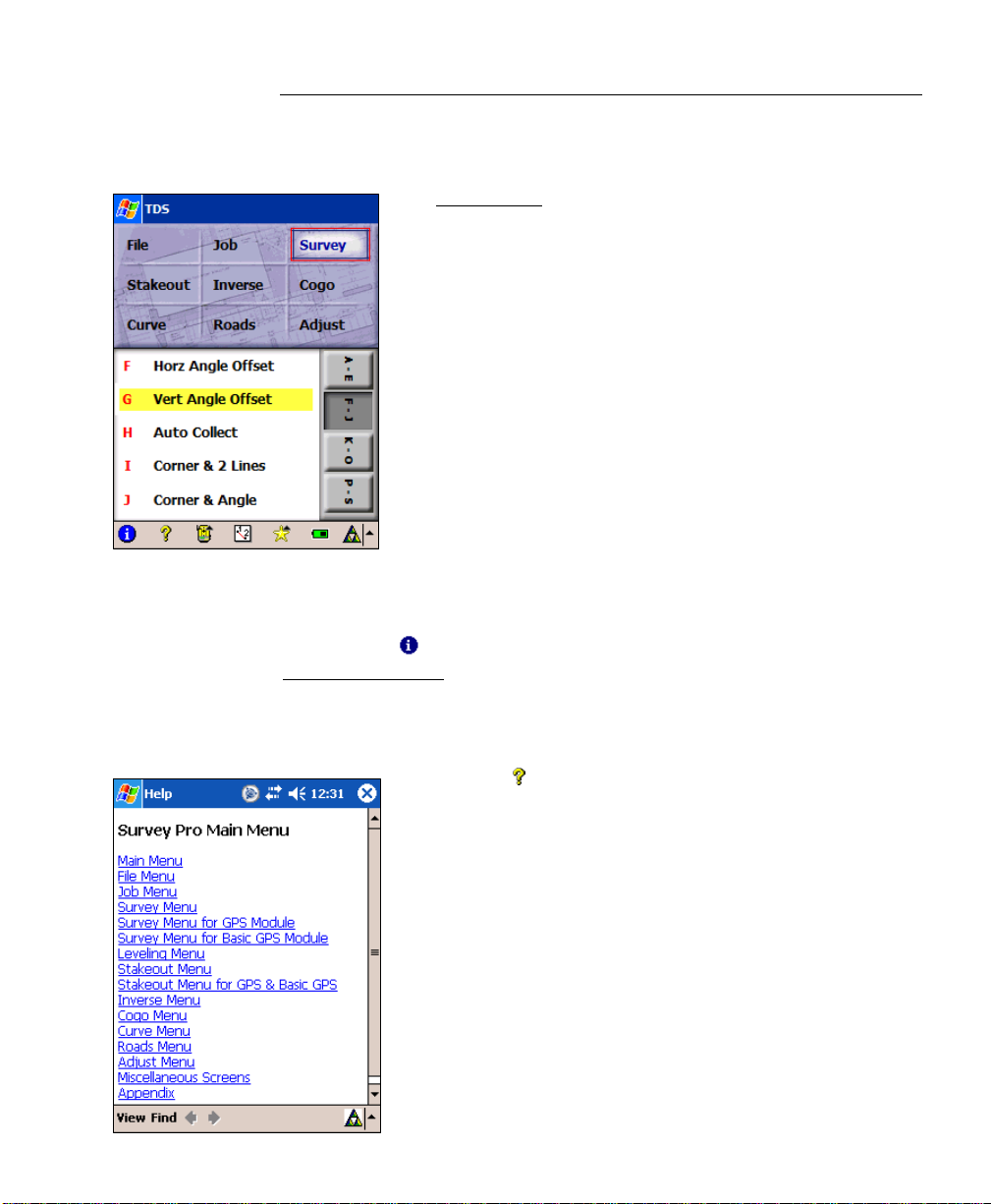
Main Menu
The Main Menu is the starting point where all the other
Survey Pro screens described in this manual are
accessed.
The area at the bottom of the screen is called the
command bar. The small buttons in the command bar
are used as follows:
About Survey Pro
Tapping the icon or selecting File | About Survey Pro opens the
About Survey Pro
screen. See Page R-33.
Online Help
Tapping the button opens the online help, which allows
you to access information similar to the information you
would find in the reference manual for each screen.
R-3
Page 12
Survey Pro Reference Manual
Surveying Mode
The instrument icon indicates which collection mode the software
is running in. There are three possible surveying modes:
Conventional,
open a list of options to do any of the following:
• Switch to another instrument mode.
• Select a different instrument profile.
GPS, and Leveling. Tapping this icon will
• Quickly access the Instrument Settings
screen (Page R-36).
Map View
A map view of the current job can be displayed by tapping the
button. See Page R-455.
Quick Pick
The (Quick Pick) button is used to quickly access any of a variety of
commonly-used Survey Pro routines. The l ist of routines available is
customizable using the Quick Pick Editor
The User’s Manual also contains more information on using the
Quick Pick button and Quick Pick Editor
(Page R-450).
.
Battery Level
The battery icon at the bottom of the Main Menu displays the
condition of the Survey Pro’s rechargeable battery. The icon has five
variations depending on the level of charge remaining:
75%, 50%, 25%, 5% and charging.
100%,
Tapping the battery icon is a shortcut to the Microsoft Power Settings
screen. You can get more information while viewing this screen by
tapping
R-4
then
.
Page 13

Main Menu
Other Command Bar Buttons
There are additional command bar buttons availab le i n scre ens other
than the Main Menu. Each is described below.
(OK): Performs the desired action then closes the current screen.
(Cancel - Red X): Closes the current screen without performing the
action intended by the screen.
(Close - Green X): Closes the current screen.
(Settings): Opens the Settings screen (Page R-36) associated with
the current screen.
(GPS Status): This is used to view the current status and access
the settings for a GPS receiver when using the GeoL ock feature (Page
R-168). It is only available from the Remot e Control
screens when using a Trimble or Geodimeter robotic total station.
and Remote Shot
R-5
Page 14

Page 15

File Menu
The File Menu contains routines to transfer files between the data
collector and another device.
A: Open / New
B: Save As
C: Import
D: Export
E: Control File
F: Backup / Restore Job
G: Transfer
H: Register Modules
I: About Survey Pro
J: Exit
R-7
Page 16
Survey Pro Reference Manual
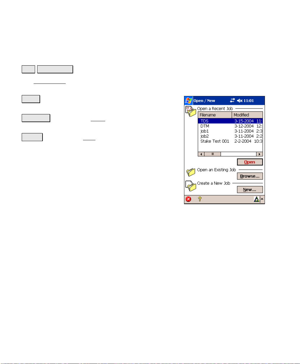
Open / New
File Open / New.
The Open / New screen is used to open a recent job or create a new
one. This screen also appears when Survey Pro is first started.
Open : opens the job selected in the Open a Recent Job
list.
Browse… : will open the Open screen (Page R-14) where
an existing job to open can be selected.
New… : will open the New screen (Page R-9) where a
new job can be created.
R-8
Page 17
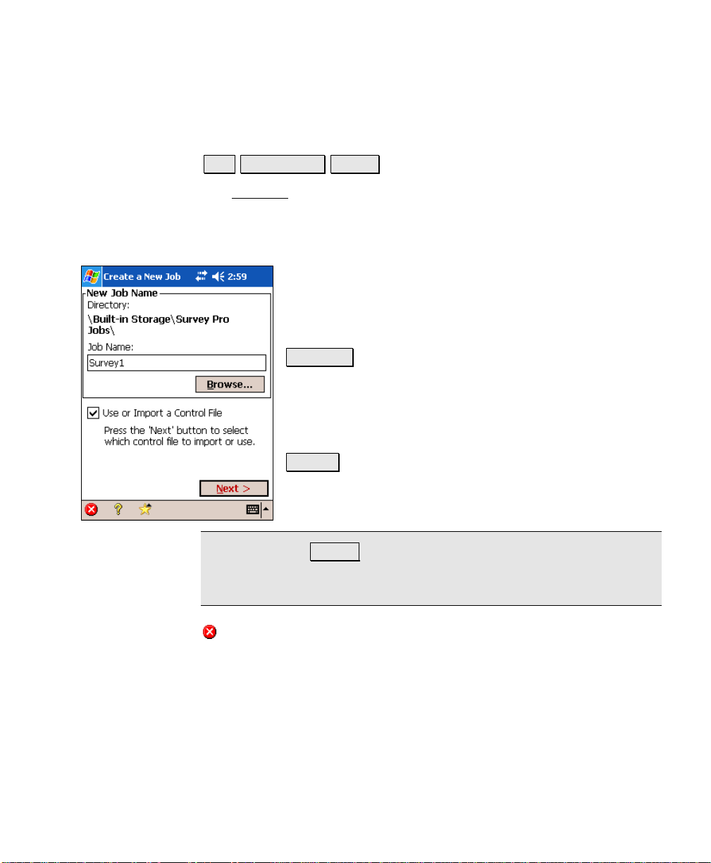
New Job
File Open / New New….
The New Job wizard is used to create a new job.
Create a New Job 1
Directory: displays the directory where the current job
will be stored.
Job Name: is where the name of the new job is entered.
The default name is the current date.
Browse… : allows you to select a different directory
where to store the new job.
Use or Import a Control File: When checked, you can
select an external control file or import the points from a
different job as control points.
Next > : opens the next screen. The screen that opens
depends on if a control file will be used.
File Menu
Note: Pressing Next> may result in a warning if you have chosen a
folder in the data collector’s RAM instead of a location on an external
CF card. See Page 58 for more information.
(Cancel): cancels the creation of a new job and brings you back to
the main menu.
R-9
Page 18
Survey Pro Reference Manual
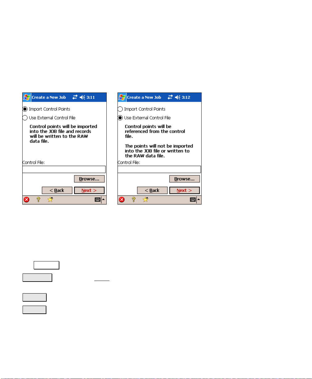
Create a New Job 2 – (Imported or External Control File)
This screen will only open next when a control file will be used or
imported.
Import Control Points: When selected, the points in the control file
will be imported into the new job.
Use External Control File: When selected, the control points in the
control file will be accessible from the new job, but will not be
imported.
Control File: displays the path and control file name selected with
the Browse… button.
Browse… : will open the Open screen (Page R-14) where an existing
job can be selected as a control file.
< Back : returns you to the previous screen.
Next > : opens the next screen.
R-10
Page 19
File Menu
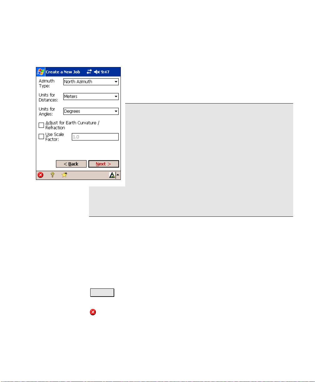
Create a New Job 3
Azimuth Type: specifies if you are surveying with a
North Azimuth or South Azimuth.
Units for Distances: specifies if your distances will be
entered in International Feet, U.S. Feet, or Meters.
Note: You can enter a distance in any distance field in
units other than what is set for the job by appending the
distance value with the following characters:
y f or ft or ift International Feet
y usf or usft US Survey Feet
y i or in Inches
y m Meters
y cm Centimeters
y mm Millimeters
Once the cursor leaves that field, the distance will be converted
automatically. (A space between the value and the unit abbreviation
is optional.)
y c or ch Chains
Units for Angles: specifies if angles will be entered in Degrees or
Grads.
; Adjust for Earth Curvature / Refraction: When checked, the
elevations recorded from all shots will be adjusted to compensate for
earth curvature and refraction.
; User Scale Factor: When checked, all horizontal distances when
taking shots will be adjusted by the scale factor entered here.
Next > : opens the final screen, which can be one of two different
possible screens depending on if a control file is being imported.
(Cancel): cancels the creation of a new job and brings you back to
the main menu.
R-11
Page 20
Survey Pro Reference Manual
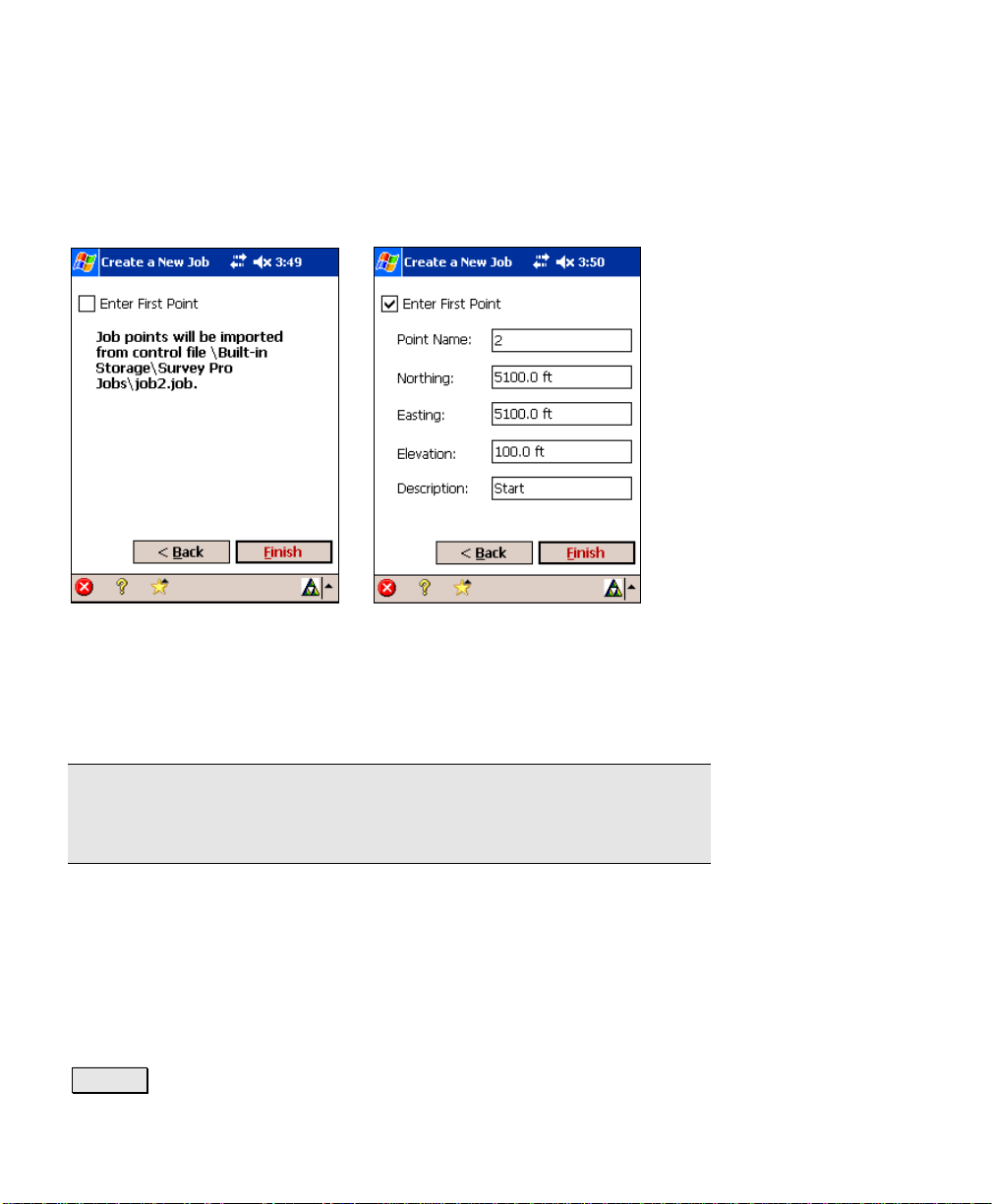
Create a New Job 4 – (Imported Control File)
This screen will only open when a control file is being im ported.
Screen when checkbox is
unchecked.
Enter First Point: When this box is checked, the additional fields will
appear allowing you to create a new point.
Note: Although all new jobs must have at least one point, creating a
new point when importing a control file is optional since points are
already being loaded into the job in the form of control points.
Point Name: is the name of the initial point.
Northing: is the Y-coordinate of the initial point.
Easting: is the X-coordinate of the initial point.
Elevation: is the elevation of the initial point.
Description: is the description of the initial point.
< Back : returns you to the previous screen.
R-12
Screen when checkbox is
checked.
Page 21
File Menu
Finish : stores a new job file and raw data file using the specified
information.
(Cancel): cancels the creation of a new job and brings you back to
the main menu.
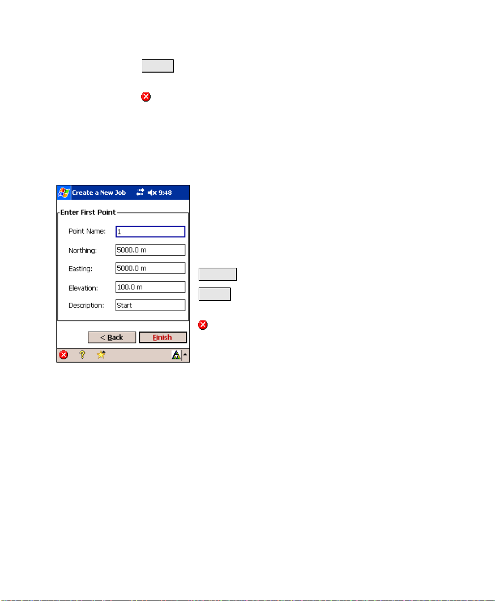
Create a New Job 5 – (External or No Control File)
Point Name: is the name of the initial point.
Northing: is the Y-coordinate of the initial point.
Easting: is the X-coordinate of the initial point.
Elevation: is the elevation of the initial point.
Description: is the description of the initial point.
< Back : returns you to the first screen.
Finish : stores a new job file and raw data file using the
specified information.
(Cancel): cancels the creation of a new job and brings
you back to the main menu.
R-13
Page 22
Survey Pro Reference Manual
Open
File Open / New. Browse….
The Open screen is used to open any existing job and is required to
open a job that is not listed in the Recent Job list in the
Open / New
A list of all the jobs in the current directory is displayed.
Simply tap on the job name that you want to open and
then tap
Note: TDS CR5 files can be opened just like any Survey
Pro JOB file. When a CR5 file is opened, it is
automatically converted and stored to a JOB file with
the same name. If a matching RW5 raw data file exists,
it too will be converted and saved to a Survey Pro RAW
file with a note inserted indicating that the conversion
took place.
When a job is being opened, the Loading JOB file screen
will open briefly and display the status of the loading
process.
screen.
.
R-14
Page 23
File Menu
Save As
File Save As.
The Save As screen allows you to save a copy of the current job under
a new name. The copy that is created will then become th e current
job.
The Save As
operating system. Simply enter a new name for the
current job and then tap the Save button.
Note: It is not necessary to include the .JOB extension
since it will automatically be added for you.
dialog box is identical to that found in the
R-15
Page 24
Survey Pro Reference Manual
Import
File Import.
The Import screen is used to add the points from another source into
the current job or import the data from a LandXML file to the current
job.
Warning: Coordinate values can change when they are imported!
Importing coordinates from any source other than a JOB file requires
that the distance units used in the source file be specified. It is not
necessary to specify the distance units when importing coordinates
from a JOB file since those units are written within the file.
If importing coordinates where the distance un its in the source file
are different than the distance units for the current job, the im ported
coordinates will be converted to the current job’s distance units when
they are imported. This is normally the desired result, but it can
cause a problem if any distance units were set incorrectly. This
situation can most commonly occur when working with International
Feet and US Survey Feet where the conversion from one to the other
is not always obvious.
Usually the difference between International Feet and US Survey
Feet is negligible (2 parts per million), but when dealing with State
Plane or UTM mapping plane coordinates, which are often very large
in magnitude, the difference can be substantial if the coordinates are
converted from one format to the other.
If importing coordinates from a source, such as an HP 48, where you
are not sure if the units are in International Feet or US Surve y F eet
into a job that is set to International Feet or US Survey Feet, you will
usually just want to import them without any conversion being
performed. To do this, be sure to select the same distance units for
the source file as those set for the current job.
R-16
Page 25
File Menu
Coordinates from a variety of file typ es can be im ported into the
current job. The first Import
types listed below. The next screen that opens depends on the
selection made here.
• Job Files (*.JOB): import coordinates from another
Job file.
• Coordinate Files (*.CR5): import coordinates from
a TDS CR5 coordinate file.
• GPS Files (*.GPS): import coordinates from a TDS
GPS coordinate file.
• Text Files (*.TXT): text files can contain coordinates
in several different possible formats. The Import
ASCII Wizard is used to define the format of the text
file being imported.
• Text Files (*.CSV): this is a simplified text file
import routine where the source file is comma
delimited and has a *.CSV extension.
• LandXML Files (*.xml): imports points, alignments, polylines,
and parcels from a LandXML file.
screen is used to select from the file
Import *.JOB Coordinates
When importing coordinates from anot her *.JOB file, the Import
screen is used, described above.
A list of all the jobs available in the current directory is displayed.
Simply tap on the job name that you want to import and then tap
button. The points in the selected job will be added to the
the
points in the current job.
R-17
Page 26
Survey Pro Reference Manual
Import *.CR5 Coordinates
When importing a CR5 file, you will first be prompted to
select the layer where you want the new data stored.
Select a layer and tap
In the next screen, select the distance units that the
coordinates were stored in and tap .
to continue.
Import *.GPS Coordinates
When importing a GPS file, you will first be prompted to
select the layer where you want the new data stored.
Select a layer and tap
In the next screen, select the distance units that the
coordinates were stored in and tap .
When importing coordinates from both a TDS CR5 and GPS file from
the same job, the GPS coordinate will be linked to the coordinates in
the CR5 file. For more information on this, refer to the GPS User’s
Guide.
to continue.
Import *.TXT Coordinates
Since the coordinates in an ASCII *.TXT file can be
stored in a variety of formats, two screens are used to
define the format of the file that is being imported once a
layer is selected. The source *.TXT file can contain
either plane coordinates or geodetic coordinates.
Delimiters: is the character that separates each column
of text in the ASCII file.
Units: are the units that the distances in the file were
stored in.
Coordinates: is used to specify if the coordinat es are
plane coordinates, geodetic coordinates in degreesminutes-seconds format, or geodetic coordinates in
decimal format.
R-18
Page 27
File Menu
; Skip the first row: should be checked if the first line in the ASCII
file contains non-coordinate information, such as a heading.
Next > : opens the second screen.
Import *.TXT Coordinates – Screen Two
Name Column No. / Start Point Name : When the first option is
selected here, the column number used for the name field in the
*.TXT file is specified here. When the second opti on is selected, it is
assumed that the *.TXT file does not contain point names and will
assign the first point the name specified here and increment to the
next available point name for the remaining points.
Columns: is where the column number for each specified
coordinate exists in the source *.TXT file. The
coordinates types displayed here can either be for plane
coordinates or geodetic coordinates depending on the
selections made in the previous screen. If a coordinate
has a checkbox, which is unchecked, it is assumed that
the source *.TXT file does not contain columns for that
type of coordinate.
; Specify Missing Elevation Threshold: if the source
file was created from coordinates with no elevations, but
the file contains an elevation column with values, such
as 0, check this box and indicate the value in the field
that will appear to the right.
Preview : opens the ASCII Import Preview window
containing all the point data that will be imported. This
is useful to check for errors before actually importing new data.
< Back : returns to the previous screen.
Finish : imports the new point data into the current project.
R-19
Page 28
Survey Pro Reference Manual
Import LandXML Coordinates
Points, alignments, polylines, and parcels can be imported from a
LandXML file.
The way the LandXML data is imported depends on how the data is
stored in the source file and how the settings are
configured in the two screens described below.
Consult the User’s Manual for more information on the
conditions that affect how the data is imported.
On specified layer: will import all the data on the
specified layer.
On different layers by groups: will import points,
alignments, and parcels to layers named by the group
name for the data in the source file. If the group name is
an invalid layer name (e.g., it is empty or contains
invalid characters), the data will be stored to the active
layer.
Next > : opens the second configuration screen.
Import polylines, alignments and parcels: When this is checked,
polylines, alignments and parcels will be imported, as well as the
points. When unchecked, only the points will be
imported.
Import parcels to the specified layer: When this is
checked, imported parcels will be stored to the sel ected
layer. If unchecked, parcels will be stored to the layer
specified in the previous screen.
For more information on how parcels are imported,
consult the User’s Manual.
Point and Line Descriptions: You can select what
information to use as the description for imported lines
and points in the corresponding two fields.
Lines can either be assigned the name or description
from the source file and points can either be assigned the
description or code from the source file.
R-20
Page 29
File Menu
Back : returns to the previous screen.
Import : imports the specified data into the current project. A
results screen will open listing the details of the imported data.
Confirm Point Replace
If a point being imported has the same name and the same
coordinates as a point that is already in the current job, it is ignored
and a message will be displayed after the remaining points ar e
imported to indicate this.
If an imported point is encountered with the same name, but with
different coordinates as a point in the current project, the Confirm
Point Replace screen will open.
Yes : will replace the point in the current job with the
point being imported.
Yes to All : will replace the point in the current job with
the point being imported and perform the same action for
any remaining duplicate points.
No : will not import the duplicate point, keeping the
coordinates for the existing point unchanged.
No to All : will not import the duplicate point, keeping
the coordinates for the existing point unchanged and
perform the same action for any remaining duplicate
points.
Rename : will store the new point in the current job
under the name specified in the Starting At field.
Rename All : will store the new point in the current job under the
name specified in the Starting At field and perform the same action for
any remaining duplicate points, storing them with the next available
point name.
Start At: is the point name assigned to the imported point when
using the Rename or Rename All functions.
R-21
Page 30
Survey Pro Reference Manual
Compare Coordinates… : will open a dialog box showing the
coordinates for the duplicate points to assist in making a decision of
how to handle the new point.
Stop Importing : will not import the current duplicate point and will
stop importing any remaining points. All previous points wi ll still be
imported into the current job.
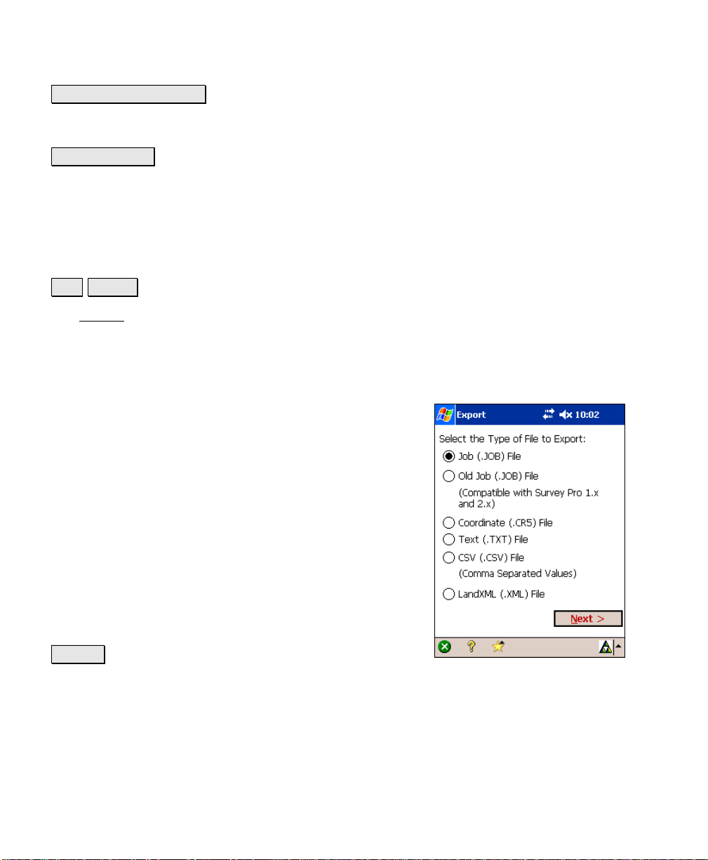
Export
File Export.
The Export screen allows you to export selected points from the
current job to a new job or to a coordinate file in another format. You
can also export all the objects in the current job to a LandXML file.
This first screen is used to specify the type of file that you want to
export data to.
Job (.JOB) File: When selected, the points are exported
to a TDS JOB file.
Old Job (.JOB) File: When selected, the points are
exported to a TDS JOB file that is compatible with
versions of Survey Pro for Windows CE earlier than 3.0.
Coordinate (.CR5) File: When selected, the points are
exported to a TDS CR5 coordinate file format.
Text (.TXT) File: When selected, the points are exported
to an ASCII text file.
CSV (.CSV) File: When selected, the points are exported
to an ASCII text file that is comma delimited and the file
is automatically given a *.CSV extension.
Next > : opens the next screen, which is determined by
the selected file type.
R-22
Page 31

File Menu
Export – Screen Two
The second Export screen will open for any file type that was selected
in the previous screen except LandXML. This screen is used to select
the points from the current project that you want to export to the
selected file type. (Exporting to a LandXML file is described later.)
To/From… : allows you to specify a range of points to
export.
Tap Points… : allows you to select the points to export by
tapping them from a map view.
: The power button provides additional point selection
options, which include selecting all control points, all
non-control points and selection by description.
< Back : returns to the previous screen.
Next > : opens the next screen, which is determined by
the selected file type.
Export *.JOB Coordinates
When exporting to another *.JOB file, the Save As screen is opened
where the file name and location is entered f or the new *.JOB file.
Export Old *.JOB Coordinates
This option functions exactly as the Export *.JOB rout ine, described
above, only the resulting file is written to be compatible with the
Survey Pro Version 2.x format, and earlier.
R-23
Page 32

Survey Pro Reference Manual
Export *.CR5 Coordinates
The Export CR5 dialog box will open when exporting
coordinates to a TDS CR5 coordinate file.
CR5 File Options: specifies if the resulting file should be
Sequential or Non-Sequential. (The HP 48 data collector
can only use sequential coordinate files .)
< Back : returns to the previous screen.
Export : exports the selected coordinates to the new CR5
file.
Export *.TXT Coordinates
Since the coordinates in an ASCII *.TXT file can be
stored in a variety of formats, two screens are used to
define the format of the resulting file.
Delimiters: is the character that separates each column
of text in the ASCII file.
Coordinates: is used to select if the resulting
coordinates should be plane coordinates, geod etic
coordinates in degrees-minutes-seconds format, or
geodetic coordinates in decimal format.
Units: are the distance units that will be written to the
resulting TXT file. These units are automatically set to
the same units that are set for the current job.
; Headers in the first row: When checked, a heading
describing each column is inserted in the first row. For
example, the following header could be insert ed:
Name,Northing,Easting,Elevation,Description
< Back : returns to the previous screen.
Next > : opens the second screen.
R-24
Page 33

File Menu
Export *.TXT Coordinates – Screen Two
Select the desired order and format for the resulting TXT
file from the list of options.
Finish : exports the selected points to the TXT file.
Export *.CSV Coordinates
This routine is identical to the Export *.TXT Coordinates
routine, described above with the exception that th e
formatting for the exported file is automatically set to
comma delimited and the extension for the file name will
be *.CSV.
Export LandXML (.XML) File
Unlike the other export routines, which only export
points, the LandXML export routine allows you to export
points along with polylines and alignments.
Export polylines and alignments: will export the points
in the current project as well as any polylines and
alignments. If this is unchecked, only the points will be
exported.
Export polylines on the specified layer as parcels:
will export the polylines on the selected layer as parcels.
(Polylines on other layers will still be exported, only not
as parcels.)
Export point description as: allows you to select to
export the point descriptions as LandXML descriptions
or codes.
R-25
Page 34

Survey Pro Reference Manual
Import Control Points
File Import Control.
The Import Control screen is used to manage a control
file for the current job.
Import… : opens the Open screen (Page R-14) where an
existing job can be selected as a control file. The control
points will then be imported into the current job and
stored to the CONTROL layer.
External Control File: displays the path and file for the
current external control file (if one is used).
Clear : clears the current external control file.
Browse… : opens the Open screen (Page R-14) where an
existing job can be selected as an external control file. (If
any point names in the external control file are also used
in the current job, the control file cannot be used.)
Backup / Restore Job
File Backup / Restore.
The Backup / Restore wizard consists of a series of
screens that are used to backup or restore all the files
associated with the current job.
The routine also gives you the option of st oring a
snapshot of a customized map view to the archive. This
can then be used to visually identify an archive.
Any number of backups can be created for a particular
job. All the existing backups for the current job are
listed in the main Backup / Restore
other information including the date the backup was
created, the number of files stored in the archive and if
the archive includes a snapshot. Archives that include a
snapshot are shown with a
R-26
screen, along with
icon, while those without a
Page 35

File Menu
snapshot have a
icon. A new (empty) archive has a icon.
All of the backups for a particular job are physically stored to a single
compressed file located in the \Jobs directory on the data collector.
This file will have the same filename as the curren t j ob, only the
*.Backup extension is appended to the name. For example, the
backups for a job with a filename of Smith.Job will be stored in a file
called Smith.Job.Backup.
New Archive… : opens the New Archive screen where a
name is entered for the new backup archive being
created. Once created, an empty archive will be listed in
the main Backup / Restore
screen, which can then be
selected to backup the current job.
Delete Archive… : opens a prompt asking if you are sure.
If you select Yes at the prompt, the archive selected from
the main Backup / Restore
screen will be deleted.
Properties… : opens the Archive Properties screen.
Backup: When selected, tapping Next> will begin the
backup routine where the data for the current job will be
stored to the selected archive.
Restore: When selected, tapping Next> will begin the
restore routine where the data from the selected archive will be
restored, overwriting the current job.
Next> : accesses the next screen.
R-27
Page 36

Survey Pro Reference Manual
Backup / Restore - Archive Properties
File Backup / Restore Properties….
The Archive Properties screen lists the files stored
within the selected archive along with other information.
The file sizes listed in this screen are in bytes. Since all
backup archives are compressed, the file sizes displayed
represent the compressed files, or the amount of space
actually being used by the file(s) on the data collector.
View Snapshot… : will display the snapshot from the
selected archive if one was included when the archive
was originally created.
R-28
Page 37

File Menu
Backup / Restore – Backup
When performing a backup, all the files associat ed with the current
job are listed and will be included in the archive.
; Create Snapshot: When checked, the next screen will
prompt you to create a snapshot of the current job’s map
view, which will then be included in the archive.
< Back : returns to the previous screen.
Backup : accesses the next screen.
Backup / Restore - Create a Snapshot
The Create a Snapshot screen is a map view that is used
to configure the map as desired and the resulting image
will be saved in the archive as a snapshot along with the
job files.
(OK): will create the archive along with a snapshot of
the map as it is configured on the screen.
(Cancel): will create the backup archive without a
snapshot.
R-29
Page 38

Survey Pro Reference Manual
Backup/Restore – Restore
When restoring the job files from an archive, the
archived files will replace the existing files of the current
job.
Warning: If you do not want to lose any new data that
was collected after the archive being restored was
created, you should first backup the current job to a new
archive before restoring an older archive.
< Back : will return to the previous screen.
Restore : will restore the backed up job from the
selected archive. The current job is then deleted and
replaced by the backup job.
R-30
Page 39

File Menu
Transfer
File Transfer.
The Transfer screen allows you to transfer files between the data
collector and another device running TDS software.
Connecting to: specifies which device you are
communicating with from the following options:
• HP48: if you are connecting to a Hewlett Packard
HP48 calculator.
• Husky: if you are connecting to a Husky FS-ser ies
data collector.
• Ranger / TSCe / ACU / Pocket PC: if you are
connecting to any of the devices listed.
• Windows PC: if you are connecting to a personal
computer that is running Windows CE Services.
• Geodimeter 600: if you are connecting to a
Geodimeter 600-series total station running TDS
onboard software.
COM Port: specifies which COM port you are using on the l ocal
machine.
Baud Rate: specifies the communications speed. The baud rate must
match in both units for successful communications.
Parity: specifies the parity. The parity must match in both units.
When in doubt, select None here. All transfers are controlled from
the PC when in this special mode.
Enter Server Mode : places the data collector in server mode where all
file transfers are controlled from a PC running either TDS Survey
Link or TDS ForeSight. Tapping Cancel will disconnect server mode.
Send File… : will open the Open dialog box where the file that you
want to send can be selected. Once selected, the file is sent from the
data collector to the specified device. A progress bar will be displayed
R-31
Page 40

Survey Pro Reference Manual
that indicates how much of the file has been transferred. Tapping
Cancel will stop the file transfer.
Note: The Send routine should be initiated shortly after issuing the
receive command on the other device.
Receive File… : allows you to receive a file from another device. This
should be tapped prior to issuing the Send command on the other
device. Tapping Cancel will stop the file transfer.
Register Modules
File Register Modules.
The Register Modules screen is used to upgrade the Survey Pro
software. Refer to the User’s Manual for more information on
registering additional modules.
If no modules have been registered, Survey Pro will run
in Demo Mode. When running in Demo Mode, users are
able to test and use every routine availabl e in the
software. Although, Demo Mode limits all jobs to no
more than 25 points. If a job exists on the data collector
that contains more than 25 points, it cannot be opened
while running in Demo Mode.
Registered: Indicates that the corresponding module
has been added.
R-32
Page 41

Enter Registration Code : Opens the Register screen,
shown here, where the registration number for a
particular module can be entered.
About Survey Pro
File About Survey Pro.
The About screen displays the version of the Surve y P r o
CE software.
File Menu
Hardware Information : is a shortcut to the Windows
System Information screen.
Exit
File Exit.
This will close the Survey Pro software and return you to
the operating system installed on your data collect or.
R-33
Page 42

Page 43

Job Menu
A: Settings
B: Edit Points
C: Edit Polylines
D: Edit Alignments
E: Auto Linework
F: View Raw Data File
G: View DTM
H: Manage Layers
I: Job Information
J: Calculator
K: Manage Pictures
L: Take Picture
R-35
Page 44

Survey Pro Reference Manual
Settings
Job Settings.
See Page R-100 if running in RTK GPS mode.
The Settings
where each individual screen accesses different types of settings.
screen actually consists of several separate screens
Instrument Settings
Job Settings Instrument Settings.
The Instrument Settings screen is actually the first of
multiple screens used to identify and configure the
instrument(s) you are using with Survey Pro. The
correct settings must be configured for successful
communications between the data collector and the
instrument.
The upper portion of the first Instrument Settings
lists the names of all the instrument profiles on the data
collector. The other columns list the COM Port, Brand,
and Model of the instrument defined in each profile.
Manual Mode: is a special profile that cannot be deleted.
When activated, all surveying is performed without
being connected to an instrument and all shot data must
be entered manually.
screen
Note: When running in leveling mode, the Instrument Settings… can
be selected for Manual Mode to open the Level Method screen
described on Page R-40.
Instrument Settings : opens the next Instrument Settings screen
where the settings in the selected instrument profile can be modified.
R-36
Page 45

Job Menu
Note: When editing an existing instrument profile, you cannot modify
the instrument brand or model.
Create New Instrument : opens the next Instrument Settings screen
where you can configure the settings for a new instrument and create
a new instrument profile.
Activate : activates the selected instrument profile.
GeoLock : opens the GeoLock Settings screen (Page R-176).
Delete : deletes the selected instrument profile.
Import : imports an instrument profile from an instrument profile
file that was previously loaded on the data collect o r.
Export : saves the selected instrument profile to a file, which can
then be transferred to another data collector and then imported.
Warning: Performing a hard reset on the data collector will result in
all the user-created instrument profiles to be deleted. It is
recommended that all instrument profiles be exported to files so in
the event of a hard reset they can be recovered using the Import
routine.
R-37
Page 46

Survey Pro Reference Manual
Instrument Settings – Screen Two
The second Instrument Settings screen opens whenever a new
instrument profile is being created, or when an existing profile is
being edited.
The options available on this screen will vary slightly depending on
the total station model selected.
Name: is the name of the instrument profile being
created or changed. This is the name that appears in the
list on the first Instrument Settings
Brand: is where you specify the manufacturer of the
instrument that you are using from a dropdown list.
Model: is where you specify the model of the instrum ent
that you are using from a dropdown list.
Serial Port: is the serial port on the data collector used
for communications with the total station. (Bluetooth can
also be selected for wireless communication b etween the
data collector and a compatible total station.)
Baud Rate: is the speed at which communication occurs
with the total station. This must match the baud rate
configured within the total station.
screen.
Parity: is the parity used for communication with the instrument.
This must match the parity setting configured within the total
station.
PIN: (applicable only when using a supported total station) is the
Personal Identification Number that was entered in the total station.
These numbers must match for successful communications.
Bluetooth… : (applicable only when using Bluetooth with a supported
total station) accesses the Bluetooth configuration screen that comes
with the Bluetooth driver software where you can quickly check or
change the virtual COM port and favorites.
Note: See the User’s Manual for more information on configuring
Bluetooth with a supported total station.
R-38
Page 47

Job Menu
Defaults : will set the Serial Port, Baud Rate and Parity to their default
values based on the selected total station.
Instrument Settings… : accesses the settings that are specific for the
selected total station.
Send to Instrument : (applicable only to specific total stations) will
send the selected instrument settings to the total station. This is
particularly useful with robotic total stations after the total sta tion
has been reset.
NOTICE:
The settings that are available after tapping the
Instrument Settings… button in non-leveling mode directly control
the settings that are built into the selected total station. Since total
station manufactures release new models every year, TDS cannot
maintain the necessary set up documentation for every existing
model and the models that are not yet available. The set up
procedure for your particular total station is better handled by t h e
total station manufacturer, or your instrument’s dealer.
If you have specific questions on the set up of your total stati on y ou
should refer to the documentation that was included with your total
station. The numbers listed below are provided for your convenience:
Trimble: 800-538-7800
Zeiss: 800-538-7800
Geodimeter: 800-538-7800
Leica: 800-327-4773
Nikon: 516-547-8500
Pentax: 800-729-1419
Topcon: 800-223-1130
R-39
Page 48

Survey Pro Reference Manual
Level Method
Job Settings Instrument (select Manual Mode) Instrument Settings…
The Level Method screen is used to select the leveling method you
want to use while using Manual Mode while running in leveling mode.
This will affect the type of data you are prompted for when taking
shots.
Three Wire: Prompts for shot data will require upper,
center, and lower wire readings.
Single Wire: Prompts for shot data will require center
wire readings only.
Electronic: Prompts for shot data will require a vertical
and horizontal distance.
Trigonometric: Prompts for shot data will require a
zenith angle and horizontal distance.
R-40
Page 49

Job Menu
Units Settings
Job Settings Units.
The Units Settings card defines the units that are used within the
software, sent from the total station, entered from the keypad an d
displayed on the screen.
Units for Distances: defines the units used for length as Meters,
International Feet, or US Survey Feet.
Note: You can enter a distance in any distance field in
units other than what is set for the job by appending the
distance value with the following characters:
y f or ft or ift International Feet
y usf or usft US Survey Feet
y i or in Inches
y m Meters
y cm Centimeters
y mm Millimeters
y c or ch Chains
Once the cursor leaves that field, the distance w il l be
converted automatically. (A space between the value and
the unit abbreviation is optional.)
Warning: When creating a new job, it is important that the Units for
Distances field be set to the correct units. This allows you to
seamlessly switch between different units in mid-job.
Problems can arise if these units are inadvertently set to the incorrect
units when entering new data. For example, assume a new job was
created by hand-entering a list of coordinates where the job was set to
International Feet and the coordinates being entered were in US
Survey Feet. Now assume you created another new job and correctly
set it to US Survey Feet. If you then imported the hand-entered points
from the other job, they would be converted to different units when no
conversion should have taken place. Depending on the magnitude of
R-41
Page 50

Survey Pro Reference Manual
the imported coordinates, the error after the conversion could be
significant.
Units for Angles: defines the units used for angles as Degrees or
Grads (gons).
Display Directions as: will display directions as a Bearing or Azimuth.
Azimuth type: defines if you are using a North Azimuth or a South
Azimuth.
Coord. Order: allows you to customize the labeling and or der for
coordinates used throughout the software. You can select any of the
following formats:
• N, E, Elev. (Northing, Easting, Elevation)
• X, Y, Z
• E, N, Elev. (Easting, Northing Elevation)
• Y, X, Z
Format Settings
Job Settings Format.
The Format Settings card defines the number of places
beyond the decimal point that are displayed for various
values in all screens, and how stations are defined. (All
internal calculations are performed using full precision.)
Northings / Eastings: will allow you to display from
zero to six places passed the decimal point for northing
and easting values.
Elevations: allows you to display from zero to six places
passed the decimal point for elevations.
Sq feet / meters: allows you to display from zero to four
places passed the decimal point for square feet or square
meter values.
Acres / Hectares: allows you to display from zero to
four places passed the decimal point for acre or hectare
values.
R-42
Page 51

Job Menu
Distances: allows you to display from zero to six places passed the
decimal point for distances.
Angles: allows you to include from zero to four fractional seconds
with angle values.
Stations: allows you to display stations in any of the following
formats:
• 12+34.123: displays stations where the number to the left of
the + advances after traveling 100 feet or meters.
• 1+234.123: displays stations where the number to the left of
the + advances after traveling 1,000 feet or meters.
• 1,234.123: displays standard distances rather than stations.
Files Settings
Job Settings Files.
The Files Settings card allows you to select a feature code file.
Feature Code File: displays the selected feature code file
to use with the current job. See the User’s Manual for
more information on feature codes.
Browse : Opens a dialog to select a feature code file to
use with the current job. Tap the filename and then tap
Open .
Clear : closes the currently selected file so that it is no
longer associated with the current job.
R-43
Page 52

Survey Pro Reference Manual
Descriptions Settings
Job Settings Descriptions., or (from any Description field),
Description Settings…
The Descriptions Settings
files and configure how descriptions are handled.
Use Description Code File: Mark this item to use a
description file that contains codes and click the
associated Browse button to navigate to and select the
file. Description code files contain one code/description
pair per line where the code and description are
separated by a space or a tab. (The code cannot contain
spaces.)
Use Description List File: Mark this item to use a
description file containing a list of descriptions without
codes – one description per line and click the associated
Browse button to navigate to and select the file.
Load Description List from Job File: Marking this item
results in descriptions used in the current job, as well as
any new descriptions entered, to be included in the
description list.
Add New Descriptions to Description List: Marking this item
results in only new descriptions entered since marking this box to be
included in the description list. (If the preceding box is marked, new
descriptions are added whether or not this item is marked.)
Show Description List Automatically: Marking this item results
in a drop-down list of descriptions being displayed as soon as text
is entered into a Description field. If unmarked, the list can be
displayed by selecting Show Description List using the
button associated with a Description field. Double-clicking a
description in the list will replace the entered text with the selected
description.
card allows you to select description code
power
R-44
Page 53

Job Menu
Surveying Settings
Job Settings Surveying.
The Surveying Settings card allows you to select various options that
affect how data collection is performed.
; Prompt for Description: When checked, a prompt for
a description will appear before any new point is stored
from only the routines under the Survey
123).
Note: Descriptions can be no longer than 16 characters.
; Prompt for Height of Rod: When checked, a prompt
for the rod height will appear before any new point is
stored.
; Prompt for Layer: When checked, a prompt to select
a layer will appear before any new point is stored from
only the routines under the Survey
menu (Page R-
menu (Page R-123).
; Prompt for Attributes: When checked, a prompt to
select feature information will appear before any new point is stored
from only the routines under the Survey
also requires that a feature file be selected from the Files Settings
card, described above.
; Prompt for Picture: if checked, a prompt will appear before
storing a point where you have the option of taking one or more
pictures associated with the current point. (Only available when
running on a Nomad with a digital camera.)
; Adjust for Earth Curvature / Refraction: when checked, the
elevations for new points are adjusted to compensate f or the
curvature of the earth and refraction.
; Detect Duplicate Shots: When checked, a prompt will appear
before attempting to store a second shot to the same location. This
helps to catch when robotic total stations have lost lock while
surveying. The distance tolerances set in the Repetition Settings
menu (Page R-123). This
R-45
Page 54

Survey Pro Reference Manual
screen are used in determining when two shots are at the same
location.
; Survey with True Azimuths: automates the process of adjusting
the circle on the total station when traversing so that you can survey
with azimuths rather than horizontal angles (see Page R-133).
Scale Factor: displa
factor, if one is configured.
Setup Scale… : access the Scale Settings screen where a mapping
plane scale factor can be configured in a variety of ways, or disabled.
ys the details on the current mapping plane scale
Scale Settings
Job Settings Surveying Setup Scale.
The Scale Settings screen is the starting point for setting up a
mapping grid scale factor. Once configured, you will return to the
Surveying Settings
scale settings.
Do not use a scale factor: This option will disable any
mapping plane scaling that is currently enabled.
Use a single combined scale factor: This uses a single
combined scale factor that is provided for you, or one can
be computed with the Calculate Scale
Use a grid factor with sea level correction: This
option uses a mapping plane scale factor that is adj u sted
for elevation changes.
Use automatic map plane grid factor with sea level
correction: This option uses a combined scale factor that
is adjusted for elevation changes.
screen where you must then tap to save the
wizard.
Use map plane ground coordinates: When checked,
you can configure the job to use map plane ground
coordinates.
Combined Factor: is where you enter a combined scale factor if
already known, otherwise it is the combined scale factor computed
from the Calculate Scale
R-46
wizard.
Page 55

Job Menu
Grid Factor: is where you enter a map plane scale factor if alrea dy
known, otherwise it is the scale factor computed from the Calculate
Scale wizard.
Calculate Scale : This opens the Calculate Scale wizard (Page R-47),
which is used to calculate a combined scale factor or map plane scale
factor.
Setup Map Ground Coordinates : This will first check that a map
projection is selected and if not, prompt you t o sel ect one. Next, it
opens a wizard where after providing an origin point and ground
system offset coordinates, the entire job northing/easting database
will be updated with the ground coordinate system transformation.
Change Map Zone : Opens the Select Coordinate System wizard
where you can choose a mapping plane zone or localized site from the
coordinate system database file as described on Page R-224. You can
eate a new zone and datum with user-specified parameters.
also cr
Calculate Scale
Job Settings Surveying Setup Scale Calculate Scale.
The Calculate Scale wizard is available when Use a single combined
scale factor or Use a grid factor with sea level correction is selected in
the Scale Settings
factor. If a map zone is not currently selected, you will
first be required to set one up before continuing (Page
224).
Projection: displays th
zone.
Select Point: is where you specify a reference point.
Calc Scale > : opens Screen Two if Use a single combined
scale factor was selected. If Use a grid factor with sea
level correction was selected, you will return to the Scale
Settings screen and the computed grid factor will be
entered for you.
screen and is used to compute a scale
e details about the current map
R-47
Page 56

Survey Pro Reference Manual
Screen Two
Ellipsoid Height: The height of the ground above the
ellipsoid surface.
< Back : returns to the previous screen.
Solve > : opens Screen Three.
Screen Three
Mapping Plane Scale Factor: displays the scale factor
that will correct for the effects of map projection
distortion.
Ellipsoid Scale Factor: displays the scale factor to
correct for the geometric effect of your height above the
ellipsoid surface.
Ground to Grid: displays the combined scale factor that
will be used for ground to grid calculations.
Grid to Ground: displays the inverse of the combined
scale factor for grid to ground calculations.
< Back : returns to the previous screen.
Solve > : returns to the Scale Settings screen where the
combined scale factor will be entered for you.
R-48
Page 57

Job Menu
Stakeout Settings
The Stakeout Settings card contains the setting that control h ow
stakeout is performed. (The settings available depend on if you are
running in conventional or GPS mode.)
; Stake “Corners,” Not Just Even Intervals: When
staking by stations, locations where a line segment
changes, such as from a straight section to a curve, will
also be staked when this is checked.
; Stake Bisector of Non-tangent Corners: When
staking an offset to a centerline that contains a corner,
this option, when checked, will stake the corner point
where the two offsets intersect.
; Always Start Stakeout With Coarse Mode: When
checked, the EDM mode toggle button found in all
stakeout screens will initially be set to coarse mode (fast
shot). This instructs the total station to measure
distances faster, but with slightly less accuracy.
; Use Manual Updating (Remote Control): When this
is checked, a Shot button in the stakeout screens must be pressed to
take a shot. When this not checked, shots are continuously taken in
the stakeout screens. (This is only valid when running in remote
mode, using a robotic total station.)
; Design Elevation from Offset Segment: Determines where the
cut/fill value is computed from in the Offset
screens when the Offset checkbox is checked and a non-zero offset is
entered. When checked, the cut/fill value is calculated from the design
elevation of the node you are staking to. When unc hecked, the cut/fill
value is calculated from the design ele vation at the specified offset
location.
Note: If the specified offset extends beyond the end of the road
profile, the cut/fill value is always computed from the design
elevation of the node you are staking to.
and Road Stakeout
R-49
Page 58

Survey Pro Reference Manual
; Write Cut Sheet Data Only (No Store Point): When checked, as-
built points are not stored to the JOB file when staking points; only
the raw data is written to the RAW file.
; View from Gun to Rod (non-remote): When checked, the move
left or right information will be presented from the rod person’s point
of view. When unchecked it will be presented fro m the total station’s
point of view. (This option only applies when a robot ic total station is
selected in the Instrument Settings
.)
; View from Rod to Gun (remote): When checked, the move left or
right information will be presented from the rod person’s point of
view. When unchecked it will be presented from the total station’s
point of view. (This option only applies when a non-robot total station
is selected in the Instrument Settings
.)
; Prompt for Layer: When checked, a prompt to select a layer will
appear before any new point is stored from only the routines under
the Stakeout
menu.
; Prompt for Attributes: When checked, a prompt to select feature
information will appear before any new point is stored from only the
routines under the Stakeout
file be selected from the Files Settings
menu. This also requires that a feature
card, described earlier.
Note: There is no Prompt for Description checkbox as in the Survey ing
Settings card because you are always prompted for a description
when storing a point from a stakeout routine.
Use Perfect Stationing: When checked, staking locations will be
computed at perfect stationing intervals. For example, if your
starting station was 0+15 and your station interval was 100, your
next stakeout location will occur at 1+00 instead of 1+15.
Use Design Point Description as Descriptor: When checked, the
descriptor for a staked point that is stored will automatically be set to
the same descriptor used for the design point. When unchecked, the
descriptor for a stored stake point will automatically be set to the
point number of the design point that you are staking.
Point Tolerance: this setting affects the Remote Staking
routine
(Page R-284). When performing Remote Stakeout, the final gra phic
R-50
Page 59

Job Menu
screen that is displayed when you are near the stake point wi l l occur
when you are within the distance to the stake poi n t specified here.
Line Tolerance: this setting affects the Stake to Line
R-289). When staking to a line and the prism is located at a
endicular distance to the specified line that is withi n the range
perp
set here, a message will state that you are on the line.
Horizontal Distance Tolerance: This setting affects the GPS staking
routines. When you are within the specified distan ce to the location
you are staking, you are considered on that location.
Turn gun to design point: only applies to motorized total stations.
The following options are available:
• 2D (HA only): A motorized total station will turn horizontally
toward the design point after tapping the Turn Gun button in
the particular stakeout screen.
• 3D (HA and ZA): A motorized total station will turn
horizontally and vertically toward the design point after
tapping the Turn Gun button in the particular stakeout
screen.
• Automatic 2D (HA only): A motorized total station will
automatically turn horizontally toward the design point when
the stakeout screen opens.
• Automatic 3D (HA and ZA): A motorized total station will
automatically turn horizontally and vertically toward the
design point when the stakeout screen opens.
routine (Page
Cut Sheet Offset stored: The cut sheet offset information can be
stored to the raw data file in either of the follow ing formats when
performing any offset staking routine:
• Design Offset: When selected, a cut sheet report will list the
design-offset values.
• Actual Offset: When selected, a cut sheet report will list the
measured-offset values.
Level Settings
Job Settings Level.
R-51
Page 60

Survey Pro Reference Manual
The Level Setting
screen is only available when running in leveling
mode. It is used to configure all of the settings for performing a level
loop.
BS1…BSn>FS1…FSn: This sequence requires that you
take all the shots for each set to the backsight, turn to
the foresight, and then shoot all the shots for each set to
the foresight.
[BS1 FS1>FS2 BS2]n: A single set in this sequence
requires that you shoot the backsight, turn and shoot the
foresight, shoot the foresight again, turn and shoot the
backsight. Repeat for all remaining sets.
Number of Sets (n): is the number of sets you want to
shoot from each setup.
Stadia Constant: is the scale of the upper and lower
stadia (wires) in the telescope. The vertical distance
measured between these stadia multiplied by the value
entered here (usually 100) equals the horizontal distance
to the rod.
V Dist Tolerance: is the maximum change in vertical distance that
can occur between all the shots to any specific point from a single
setup. If this value is exceeded, a warning will occur.
H Dist Tolerance: is the maximum change in horizontal distance
that can occur between all the shots to any specific point from a single
setup. If this value is exceeded, a warning will occur.
; BS-FS Sight Length < Per Shot: When checked, a warning will
occur whenever the horizontal distance of each leg in any given setup
differs by more than this value.
; BS-FS Sight Length < Per Loop: When checked, the sum of the
horizontal distances measured to all the backsight shots are
compared to the sum of the horizontal distances to all th e foresight
shots. If the difference exceeds this value, a warning wi ll occur.
; Max Sight Lengths: When checked, a warning will occur
whenever the horizontal distance measured t o any point exceeds this
value.
R-52
Page 61

Job Menu
; Min Ground Clearance: When checked, a warning will occur if a
shot is taken at a location on the rod that is within this distance to
the ground.
; Max Loop Misclosure: When checked, the error computed after a
level loop is closed will be surrounded with exclamation points in the
Close Loop
screen and Level Notes screen if the error exceeds this
value.
; Upper-Lower Wire Reading <: When checked a warning will
occur if the difference between the upper stadia and crosshair exceeds
the difference between the crosshair and lower sta dia by this value.
(This only applies to the Three Wire level method.)
Load FGCS Defaults : Opens the FGCS Defaults screen, described
below, where the default tolerances for a specified level loop order
and class can be loaded.
R-53
Page 62

Survey Pro Reference Manual
FGCS Defaults
Job Settings Level Load FGCS Defaults.
The FGCS Defaults screen is used to load the default FGCS
tolerances in the Level Settings
loop specified here.
Order: indicates the order of the level loop that you want
to load the default tolerances for.
Class: indicates the class of the level loop that you want
to load the default tolerances for.
screen for the order and class of level
Tapping
Settings screen based on the FGCS specifications for the
order and class selected. (These tolerances can still be
manually changed later.)
Note: It is important to recognize that Survey Pro can
only display a warning if tolerances are not met. It is up
to the surveyor to determine if the level loop m eets the
criteria for a particular standard.
will load the tolerances into the Level
R-54
Page 63

Job Menu
Repetition Settings
The Repetition Settings card contains the settings that control how
repetition shots are performed and acceptable tolerances.
Horizontal Tolerance: a warning message will be
displayed if a horizontal angle exceeds the tolerance
entered here during a repetition shot.
Zenith Tolerance: a warning message will be displayed
if a vertical angle exceeds the tolerance entered h ere
during a repetition shot.
Distance Tolerance: a warning message will be
displayed if a distance exceeds the tolerance entered here
during a repetition shot.
; Shoot Distance To Backsight: When checked, a
distance will be measured to each shot to the backsight.
When unchecked, only the angles are measured.
; Do Not Shoot Reverse Distances: When checked,
distances are not measured during reverse shots.
; Enable Automatic Repetition: When checked, all remaining shots
after the first shot to the backsight and foresight will occur
automatically when using a motorized instrument.
Shooting Sequence: specifies the order that the shots are taken
from the following options:
• BS > FS ^ FS > BS: Backsight, Foresight, flop Foresight
Backsight
• BS > FS ^> BS > FS: Backsight, Foresight, flop Backsight,
Foresight
• BS ^ BS > FS ^ FS: Backsight, flop Backsight, Foresight, flop
Foresight
• FS ^ FS > BS ^ BS: Foresight, flop Foresight, Backsight, flop
Backsight
• FS > BS ^ BS > FS: Foresight, Backsight, flop Backsight,
Foresight
R-55
Page 64

Survey Pro Reference Manual
• FS > BS ^> FS > BS: Foresight, Backsight, flop Foresight,
Backsight
• BS ^ BS ^ > FS ^ FS ^: Backsight, flop, Backsight, flop,
Foresight, flop, Foresight, flop
Date/Time Settings
The Date/Time Settings card is used to set the date and t ime in the
data collector.
Time: displays the current time.
Date: displays the current date.
Format: Select Local to display your local time, or UTC to
display Coordinated Universal Time.
DUT Correction: is the polar wandering correction
factor, in seconds, used to convert UTC to UT1.
(UT1=UTC+DUT)
Note: The date, time and UTC are computed using
Operating System’s Date and Time values.
Set Date : will set the system date with the date that is
entered.
Set Time : will set the system time with the time entered.
Synchronize : When pressed, will zero the fractional portion of the
current time and advance to the nearest second so that the time can
be set more accurately.
R-56
Page 65

Job Menu
Buttons Settings
The Buttons Settings card is used to customize the function for the
physical buttons located on the data collector.
The upper half of the screen lists all of the customizable button’s
current assignments. A particular button must be selected from this
list prior to changing its settings from the lower half of the screen.
Assignment Within Survey Pro: is where you select the
function for the selected button when it is used with in
Survey Pro. The function of the button will switch back
to its global assignment when it is used outside of Survey
Pro. Selecting <Global> from this field will result in the
global assignment also being used from within Survey
Pro.
Global Assignment: is where you select the function for
the selected button when it is used outside Survey Pro.
TDS Defaults : will set all assignments in the Assignment
Within Survey Pro field to the TDS default settings.
System Defaults : will set all assignments in the Global
Assignment field to the system default settings and set all
the assignments in the Assignment Within Survey Pro field
to <Global>.
R-57
Page 66

Survey Pro Reference Manual
General Settings
The General Settings card can contain the following miscellaneous
settings:
; Use Enter Key to Move Between Fields: When
checked, the [Enter] key will move the cursor to the next
field in all screens. When unchecked, the [Enter] key
will perform a different function depending on the field
selected.
Note: The arrow keys can also be used to move the
cursor between fields.
; Allow Alphanumeric Point Names: When checked,
numeric or alpha character can be used for point names.
If unchecked, only numeric point names are valid.
; Always Prompt for Backsight Check: When
checked, you will be prompted if you tap
Backsight Solved
You will also be prompted if you cancel out of the Backsight Solved
screen and then tap
screen without first performing a backsight check.
from the Backsight Setup screen.
from the
Note: You will never be prompted to check your backsight when
running in Manual Mode.
; Use Classic Backsight Setup: When checked, the backsight setup
routine functions as it did in versions of Survey Pro before 4.0.
Basically the Backsight Solved
your backsight. The Check Backsight
can still be accessed manually from the Backsight Setup
; Beep When Storing Points: When checked, a beep will sound
whenever a new point is stored.
; Beep On Control Activation: When checked, a beep occurs when
any button, checkbox, or other control is tapped.
R-58
screen will not appear after solving
and Backsight Circle screens
screen.
Page 67

Job Menu
; Prompt for Description: When checked, a prompt for a
description will appear before any new point is stored from any
routine other than those included in the Survey
and Stakeout menus.
; Prompt for Layer: When checked, a prompt to select a layer will
appear before any new point is stored from any routine other than
those included in the Survey
and Stakeout menus.
; Prompt for Attributes: When checked, a prompt to select feature
information will appear before any new point is stored from any
routine other than those included in the Survey
and Stakeout menus.
This also requires that a feature file be selected from the Files
Settings card, described earlier.
; Prompt to Backup When Closing Job: When checked, you will be
reminded to backup the current job prior to closing it.
; Write Point Attributes to Raw Data: When checked, point
attributes will be written to the raw data file as well as the job file.
; Prompt for Elevation of 2D Cogo Pionts: When checked, a
majority of the COGO routines will prompt you for an elevation
before storing a 2D point. When unchecked, 2D points will be stored
without the prompt.
; Use Smart Soft Input Panel Activation: When checked, the SIP
will automatically open when the cursor is ins ide an input field and
close when the cursor is moved outside an input field.
; Always Warn if Not Saving New File to Flash Card: When
checked, a warning will open whenever a new job is saved to the data
collector’s onboard memory rather than an external CF card.
; Log Serial Port Traffic: When checked, all serial port traffic will
be logged to a text file called TDS-Log.txt for troubleshooting
purposes and is stored in the Jobs folder. The file i s automatically
overwritten when logging traffic on a date that is different from the
previous date.
R-59
Page 68

Survey Pro Reference Manual
Edit Points
Job Edit Points.
The Edit Points screen allows you to add, edit, and delete any points
in the current job.
Edit… : if only a single point is selected, this will open
the point in the Edit Point - General screen (Page R-62)
where the details of the point can be modified. If more
than one point is selected, the next Edit Points
will open where the description and layer for the selected
points can be modified simultaneously.
Note: Multiple points can be selected by tapping the first
point in a range, then tap the shift key from a soft input
panel such as the TDS Keyboard, and lastly tap the last
point in the point range. Individual points in a point
range can be selected/unselected by tapping the control
key from a soft input panel and then tapping the desired
points.
screen
Note: Double tapping on a point will open that point in the editor.
Note: The current occupy and backsight points cannot be edited.
Insert… : opens a screen where a new point can be added.
Delete… : will delete the selected point.
Find… : will search for a point by its description.
Find Next : will find the next point that contains the description
entered when using the Find… button.
Go To… : opens a dialog box where any point can be quickly located
by the entered point name.
R-60
Page 69

Job Menu
Edit Multiple Points – General
Job Edit Points Edit… General.
This screen is accessed after pressing Edit… when more than one
point is selected. The change made in this screen will be applied to
all the selected points.
Change Descriptions: When checked, allows you to
change all the selected point’s descriptions to the
Description entered in the next field.
Description: is the new description that will replace the
existing descriptions for the selected points.
Change Layers: When checked, allows you to move the
selected points to the layer selected in the next field.
Layer: is the layer where the selected points will be
moved.
R-61
Page 70

Survey Pro Reference Manual
Edit Point – General
Job Edit Points Edit… General.
The General card of the Edit Point screen is used to modify the
description, layer and feature information for the selected point.
Point Name: displays the selected point’s name.
Description: is the description for the selected point.
Layer: is the layer for the selected point.
Feature: displays the feature assigned to the selected
point, which can be modified using the Attributes
button.
Attributes : accesses the Point Feature Attributes screen
(Page R-63) where the feature attributes for the point
can be modified.
R-62
Page 71

Job Menu
Point Feature Attributes
Job Edit Points Edit… General Attributes….
The Point Feature Attributes screen is available from the above path
or whenever a point is stored when Prompt for Attributes is checked in
the Surveying Settings
Recently Used: when checked will arrange the order of
the available features so the most recently used f eatures
are listed first. Any feature in the current feature file
can be selected from the corresponding drop-down list.
The content displayed in the main portion of the window
fully depends on the attribute information associated
with the selected feature.
Note: Feature files are created using the Survey
Attribute Manager included with TDS Survey Link,
Version 7.2 or later.
screen (Page R-44).
Edit Point – Location
Job Edit Points Edit… Location.
The Location card is used to modify the northing, easting
and elevation of the selected point.
R-63
Page 72

Survey Pro Reference Manual
Edit Point – Geodetic
Job Edit Points Edit… Geodetic.
The Geodetic card applies primarily to Survey Pro with GPS users.
Refer to the GPS Reference Manual for more information on this
card.
; Has Geodetic Data: when checked, this allows you to
edit the geodetic coordinates for a poin t.
Advanced… : will open the Edit GPS Point Flags screen
to select the advanced settings for the selected point.
Edit GPS Point Flags Screen
Survey Control Points Edit Point Set Flags.
The Edit GPS Point Flags screen is used to select the
advanced settings for the selected point.
Set Up Group: is the set up group of the point. (See the
User’s Manual for more information on set up groups.)
GPS Control Point: When checked, will include the selected point in
the list of localization control points.
Use for Horizontal Localization: When checked, will use the point
for horizontal control in the localization solution.
Use for Vertical Localization: When checked, will use the point for
vertical control in the localization solution.
Use as localization calculator grid origin: When checked, identifies
the selected point as the local grid origin for computing rotation in
localization calculator solutions. (See the GPS User’s Manual fo r
more information on localization calculator.).
Accept : accepts the screen selections and returns to the previous
screen.
R-64
Page 73

Edit Polylines
Job Edit Polylines.
The Edit Polylines screen is used to add, edit, and delete
polylines in the current job.
The first screen will display a list of all the polylines that
are stored in the current job. Selecting any of the
polylines listed will display a horizontal (overhead) and
vertical (side) view of that polyline.
New… : will open the Polyline Editor where a new
polyline can be created.
Edit… : will open the selected polyline in the New
Polyline screen, described below.
Delete… : will delete the selected polyline.
Job Menu
Screen Two – New Polyline
The second screen is used to define all of the points that
are used in the polyline. Any curve information will be
entered later, but the end points must still be selected at
this point.
The current polyline is shown on color displays with bold
red lines and all other polylines are shown using thin
black lines. Only the current polyline data can be edited.
Tap Points… : opens a map view where the points in
your polyline can be tapped. They must be tapped in the
order that they occur in the polyline.
To/From… : Allows you to define a range of points to
define a polyline.
Edit… : Accesses the third screen, described next, where
R-65
Page 74

Survey Pro Reference Manual
the current polyline can be modified.
Clear : removes the current polyline.
Screen Three – Polyline Editor
Once the initial points are selected for the current p ol yl ine, the third
screen allows you to modify the polyline and define any curve and
grade information for the polyline sections.
Selecting any point in the left column of the screen wil l
select that point and the line segment that follows it up
to the next point. The selected section is then
highlighted in the map portion of the screen. Any edits
will occur on the selected section.
Remove : will remove the selected point and the line
segment that follows it. The previous line segment will
be automatically joined to the following point. The
change will only be saved if you then tap
(Cancel) will return to the previous screen without
saving the changes.
. Tapping
Clear All : will completely remove the current polyline.
The change will only be saved if you then tap .
Tapping
without saving the changes.
Curves… : Accesses the fourth screen, described below, where a
horizontal, vertical, or spiral curve can be added to the selected
polyline segment.
Horizontal / Vertical: toggles between showing the map in a
Horizontal (overhead) view or a Vertical (side) view.
<- Insert : allows you to insert a point, or a group of points in front of
the selected point. The change will only be saved if you then tap .
Tapping
the changes.
R-66
(Cancel) will return to the previous screen
(Cancel) will return to the previous screen without saving
Page 75

Job Menu
Note, if <End> is selected in the list, the <-Insert button will change
to an <-Append button to indicate that additional points will be
appended to the end of the list.
Screen Four – Add/Edit Curve
The fourth screen is used to modify a selected polyline segment that
occurs between two points. A horizontal, vertical, and/or spiral curve
can be applied to the polyline segment.
Adding a Horizontal Curve
Tap the Arc / Spiral tab.
Curve: must be set to Arc to enter a horizontal curve.
Radius | Delta | Degree Arc | Degree Chord :
allows you to specify the radius of the curve using a
variety of methods.
Turn: specifies if the curve turns toward the Right or Left
as you occupy the initial point and face the end point.
Arc: specifies if the arc of the curve is Small (less than
180°) or Large (greater than 180°).
R-67
Page 76

Survey Pro Reference Manual
Adding a Spiral
Tap the Arc / Spiral tab.
Curve: must be set to Spiral to enter a spiral curve.
Radius: is the radius of the spiral curve. (The same
radius of the circular curve adjacent to the spiral.)
Length: is the length of the spiral, measured along the
curve from the TS to the SC.
Turn: specifies if the spiral curve turns to the Right or
Left as you occupy the initial point and face the end
point.
Direction: specifies if the curve runs from where the
tangent intersects with the spiral toward where the
spiral intersects with the curve (TS->SC) or if the curve
runs from where the curve intersects with the spiral
toward where the spiral intersects with the tangent (CS-
>ST).
Adding a Vertical Curve
Tap the Parabolic Curve tab.
; Apply Curve: must be checked to enter a vertical at
curve.
Grade at EVC / BVC is the known grade at either the
end of vertical curve or beginning of vertical curve. The
grade entered here is determined by the selection made
in the Auto-Compute field.
Auto-Compute: will automatically compute the grade at
the selected point and display it on the screen. The
grade at the point that is not checked here must be
specified in the field defined above.
R-68
Page 77

Job Menu
Edit Alignments
The Edit Alignments screen is used to create and edit alignments,
which can then be used with routines such as Offset Staking
Points, Offset Lines and Road Layout.
Alignments are used to describe all of the horizontal and vertical
details of a road’s centerline. An alignment does not use existing
points to define any particular locations on the alignment, although a
point can be used to anchor the starting location, which is the same
location for both the horizontal and vertical parts of the alignment.
Any location on an alignment where a change occurs is called a node.
An alignment can contain straight sections, grades, horizontal,
vertical, and spiral curves. The horizontal and vertical portions of an
alignment are defined separately and independently, but they are
both combined within the software to create a single alignment with
horizontal and vertical characteristics.
Add / Edit Alignments
, Offset
Job Edit Alignments or Roads Edit Alignments.
The Add / Edit Alignments screen displays a list of all
the existing alignments in the current job. The right
portion of the screen shows a graphic of the horizontal
and vertical portion of the selected alignment.
New… : opens the Edit Alignment screen where a new
alignment can be created from scratch.
Edit… : opens the Edit Alignment screen where the
details of the selected alignment can be edited.
Delete… : is used to delete the selected alignment.
: The power button accesses the following routines:
• Create Points: opens the Create Points
(Page R-447) where points can be stored that
ide with the selected alignment.
coinc
screen
R-69
Page 78

Survey Pro Reference Manual
• Import .RD5 File: opens the Open
*.RD5 alignment files in the Jobs directory. Select the
desired file and tap
• Export .RD5 File: opens the Save As screen where the
current alignment can be saved to a *.RD5 file.
.
screen and lists all the
Edit Alignment
Job Edit Alignments Edit…. or
Job Edit Alignments New….
The Edit Alignment screen is used to edit an existing alignment or
create a new one.
Edit Alignment Screen – HAL Tab
The HAL (Horizontal ALignment) tab in the Edit
Alignment screen is used to enter or modify on ly the
horizontal details of an alignment.
Insert… : opens the Edit Segment screen where a new
horizontal alignment segment can be inserted prior to
the selected segment.
Edit… : opens the Edit Segment screen where the
selected horizontal segment can be modified.
Remove : removes the selected segment and
automatically joins the next segment with the previous
segment.
Note: The station and azimuth at the beginning of the selected
horizontal segment are displayed at the bottom of the screen.
R-70
Page 79

Job Menu
Edit Alignment Screen – VAL Tab
The VAL (Vertical ALignment) tab in the Edit Alignm ent screen is
used to enter or modify only the vertical det ails of an alignment.
Note: The total horizontal length of the VAL must be equal to or
greater than the total horizontal length of the HAL when the
alignment is used for road layout.
Insert… : opens the Edit Segment screen where a new
vertical segment can be inserted prior to the selected
segment.
Edit… : opens the Edit Segment screen where the
selected vertical segment can be modified.
Remove : removes the selected segment and
automatically joins the next segment with the previous
segment.
Note: The station and elevation at the beginning of the
selected vertical segment are displayed at the bottom of
the screen.
R-71
Page 80

Survey Pro Reference Manual
Edit Alignment Screen – POB Tab
The POB (Point Of Beginning) tab in the Edit Alignment
screen is used to define the starting location of the
alignment. The first horizontal and vertical segment
will always begin at this location.
Location : the starting location for the horizontal and
vertical alignments will be at the specified North, East
and Elev coordinates.
Point : the starting location for the horizontal and
vertical alignments will be at the specified Point.
Start Station: is the station on the alignment that
corresponds with the starting location or point.
Edit Alignment Screen – General Tab
The General tab in the Edit Alignment screen is used to
describe the alignment and select the layer wher e it is
located.
Description: is the description of the alignment.
Layer: is the layer where the alignment will be located.
Attributes : accesses the Point Feature Attributes screen
(Page R-63) where the feature attributes f or the
alignment can be selected.
R-72
Page 81

Job Menu
Edit Segment
The Edit Segment screen is accessed anytime an existing horizontal
or vertical segment is added or edited. A variety o f segm ent editing
screens are possible depending on the type of segment being edited or
created. Each segment editor is discussed below.
Edit Segment – Line Card
The Line card is used to add a straight horizontal line
segment in the alignment.
Length: is the horizontal length of the line.
; Make this segment tangent to previous: When
checked, the specified line will be tangent to the ending
tangent of the previous segment.
Note: When making a new horizontal segment tangent
to the previous segment, the new segment will appear in
the Edit Alignment screen tagged with a (P). This
means that if the previous horizontal segment is edited
or deleted, where the orientation changes, all subsequen t
horizontal segments that have the (P) tag will also be
adjusted so they will remain tangent to the pre vious
segments.
This does not hold true for vertical alignment segments. Vertical
segments will always begin with the specified starting grade unless
they are manually modified.
Azimuth / Bearing : is used to enter a known azimuth or bearing
of the line.
: adds the line to the current horizontal alignment.
R-73
Page 82

Survey Pro Reference Manual
Edit Segment – Arc (Horizontal Curve) Card
The Arc card is used to add a horizontal curve to the alignment.
The curve can be defined by two of the following:
• Radius : The distance from the radius point to
the curve
• Delta : The internal angle from center to
tangent points.
• Degree Arc : The internal angle equivalent to a
100-ft arc length.
• Degree Chord : The internal angle equivalent to
a 100-ft chord length.
• Length : The arc length.
• Chord : The chord length.
• Tangent : The distance from the PC or PT to the
PI.
• Mid Ord : The distance between the curve and the chord at
the center of the curve’s length.
• External : The minimum distance between the PI and the
curve.
Turn: specifies if the curve turns to the
the curve from the beginning.
; Make this segment tangent to previous: When checked, the
start of the specified curve will be tangent to the ending tangent of
the previous segment.
Azimuth / Bearing : is used to enter a known azimuth or bearing
at the start of the curve.
: adds the curve to the current horizontal alignment.
R-74
Left or Right as you face
Page 83

Job Menu
Edit Segment – Spiral Card
The Spiral card is used to add a spiral curve to the alignment.
Radius: is the radius of the spiral. (This equals the
radius of the horizontal curve tangent to the spiral.)
Length: is the length of the spiral.
Turn: specifies if the curve turns to the
as you face the curve from the beginning.
Dir: specifies if the curve runs from
to Spiral, to Spiral to Curve) or
Spiral, to Spiral to Tangent).
; Make this segment tangent to previous: When
checked, will automatically turn the spiral so the
beginning is tangent to the end of the previous seg ment.
Azimuth / Bearing : is used to specify a known
azimuth or bearing of the start of the spiral.
CS to ST (Curve to
Left or Right
TS to SC (Tangent
R-75
Page 84

Survey Pro Reference Manual
Edit Segment – Vertical Grade Card
The Vertical Grade card is used to enter a segment with
any grade.
Length: is the horizontal length of the segment.
Grade: is the grade (slope) of the segment.
Get Previous Grade : will automatically enter a grade
equal to the grade at the end of the previous segment.
Edit Segment – Vertical Curve
The Vertical Curve card is used to enter a parabolic
vertical curve to the alignment.
Length: is the horizontal length of the vertical curve.
Start Grade: is the starting grade of the vertical curve.
End Grade: is the ending grade of the vertical curve.
Get Previous Grade : will automatically enter a Start
Grade equal to the grade at the end of the previous
segment.
R-76
Page 85

Job Menu
Auto Linework
Job Auto Linework
The Auto Linework screen is used to set up custom
descriptors that can be used to generate various polylines
between points as they are shot. These features can than
be exported and used in the TDS ForeSight software.
Note: The auto linework information described below is
not written to the raw data file. If using a conversion
routine that only uses a raw data file, all linew ork
commands must be manually entered into the raw data
file in the form of a note by using the , Add Note Quick
Pick. (See the User’s manual for details on customizing
the Quick Pick list.)
Description: lists the descriptions defined from using
the Add… button, which when used during data
collection, will generate the specifi ed polyline segment (linework).
The following two wildcards can be appended to a description where
each one performs a special function.
• Asterisk (*): When a description entry ends with an asterisk,
any description entered during data collection that begins
with the same characters before the asterisk will be joined to
the previous linework entry. For exam ple, if CURB* were
used as in the screen shown here, and a description for a
point was called CURB5 or CURBSIDE, the line segment
associated with CURB* would be appended to the previo us line
segment.
• Pound sign (#): When a description entry ends with a pound
sign, any description entered during data collection that
begins with the same characters before the pound sign will
generate the associated line segment type, but if the next
description is at all different from the previous use, a new
independent line segment will be drawn. F or example, if
LOT# were used as in the screen shown above, all entries of
R-77
Page 86

Survey Pro Reference Manual
“LOT10” would be connected. If LOT15 were also used as a
description during data collection, any future use of L OT 15
would connect to the previous LOT15 entry.
Note: Linework descriptions are case sensitive.
Cmd: lists the current type of line segment (linework) that will be
created after shooting the required poin ts and storing them with the
associated Description. The following linework command options are
selected by repeatedly tapping the appropriate button:
• Line : creates a straight line between the next two points
stored with a description associated with Line.
• P-Crv : creates a curve through the next 3 points stored
with a description associated with P-Crv.
• R-Crv : creates a curve between the next two
points that are stored with a description
associated with R-Crv. After the second R-Crv
point is shot, the prompt shown will open and is
used to define the details of the curve.
R-78
Page 87

Job Menu
• T-Crv : creates a curve with a specified
incoming tangent from the next two points that
are stored with a description associated with T-
Crv. When the second point is stored, the prompt
shown here appears where the incoming azimuth
or bearing is specified.
• Rect : will compute and store the fourth and
final point that forms a rectangle or
parallelogram after three points are stored with
a description associated with Rect.
Note: At any time, the line type for any linework
command can be changed while collecting linework for a
particular feature. For example, a feature called FENCE
might primarily use the Line linework command, but might also
contain a curved section. To add a curve to the fence, you would open
the Job | Auto Linework screen and toggle Line to R-Crv prior to
storing the first point of the curve. Once the second point of the curve
is stored, the curve is defined and appended to the FENCE polyline.
This routine is enhanced with the Props command, described below.
; On: When checked, activates the associated linework command. If
a particular polyline is created and then this is unchecked for that
linework command, future points stored with the same description
would not result in any change to that polyline. But if this is then
activated again later, all future points collected using the same
linework command will be appended to the original polyline.
End: toggles between the following two functions, giving you control
in collecting data for two or more separate features that use the same
linework command:
When the map icon is displayed for this button, a polyline has
been created for the associated linework command. Tapping the
button will then allow you to detach future points using this linework
command from the current polyline, resulting in future points being
added to a new polyline.
If the button is blank and the current job contains at least one
polyline, you will be prompted to select an existing polyline. Once
R-79
Page 88

Survey Pro Reference Manual
selected, future points stored with this linework command will be
appended to the selected polyline.
Props: A single polyline can contain different line types.
The Props command will open the Auto Linework
Properties dialog box, shown here, where w h en the
checkbox is checked, the linework command will always
switch back to the specified default linework command
after changing and storing a different line type for a
particular feature.
Add… : allows you to create a new linework command.
Remove… : removes the selected linework command.
Remove All… : removes all the existing linework
commands.
Note: All linework shots require at least two points with
a particular linework command before a polyline segment is created.
If only the initial point has been stored, no polyl ine segment is yet
created.
R-80
Page 89

Job Menu
View Raw Data File
Job View Raw Data.
The View Raw Data File screen displays the raw data file of the
current job and allows you to append a note or current time entry.
Tapping any line in the raw data file will toggle a
bookmark in front of that line. The active bookmark is
shown as a green (or light-gray) circle. An inactive
bookmark is shown in red (or dark gray). See
illustration.
First : jumps to the first line of the file.
Last : jumps to the last line of the file.
Prev. : jumps to bookmark above the active bookmark.
Next : jumps to the bookmark below the active
bookmark.
Clear All : clears all bookmarks.
Time : appends the current date and time in the form of
a note to the end of the raw data file.
Note… : opens the Raw Data Note screen, described below.
R-81
Page 90

Survey Pro Reference Manual
Raw Data Note
Job View Raw Data Note….
The Raw Data Note screen is used to append a note to the raw data
file. The note can consist of any string of text, including line work
commands or codes for use with AutoCad®.
Up to 127 characters of text can be keyed into the upper
portion of the screen manually or the buttons in the
lower portion of the screen can be tapped to quickly enter
any of ten default line work commands. These buttons
can also be customized, or new buttons can be created.
Write Now! : Appends the text in the upper portion of
the screen to the raw data file.
Code Page
The Code page lists the default line work command code
buttons and/or customized buttons. Tapping any button
will enter the text associated with that button to the
upper portion of the screen.
Customize : toggles the page between normal mode and
customize mode. When in customize mode, any o f the
default line work command buttons can be customized or new buttons
created.
TDS Default (only available after tapping Customize): Restores the
default contents of the Code page. Any customized buttons will be
lost.
R-82
Page 91

History Page
The History page provides a quick way to enter a note
that was used earlier. The page lists up to the last 30
notes used.
Job Menu
Notes that were entered from the buttons on the Code
page are excluded from this list to reduce clutter since
those notes are already easily accessible.
Sort: Allows you to sort the list of previous notes using a
variety of methods.
Select : Copies the note currently selected from the list
into the upper portion of the screen where it can then be
appended to the raw data file using the Write Now!
button.
: Removes the selected note from the list.
Code Edit
Job View Raw Data Note…. Code Customize click a button
Tapping any of the 16 available button s while in
customize mode will open the contents of that b u tton in
the Code Edit
Button Label: This is the text that will appear on the
selected button. A maximum of 5 characters can be
entered here.
screen where it can be modified as desired.
Actual Text: This is the text that will be entered in the
upper portion of the Raw Data Note
selected button is tapped. A maximum of 127 characters
can be entered here.
: Saves the changes and returns to the previous
screen.
: Cancels any changes made and returns to the
previous screen.
screen when the
R-83
Page 92

Survey Pro Reference Manual
Note: Custom code buttons remain intact even when switching or
creating new jobs because the details of these buttons are stored to a
text file in the Survey Pro program folder called NoteCode.ini. If you
want to copy custom code buttons to another data collector, you must
copy this file to the Survey Pro folder on the other data collector.
View DTM
Job View DTM.
Before viewing a DTM, the Setup DTM 3D screen will open where the
DTM layers must be defined. This screen is also used to define other
parameters for the DTM.
Layers : opens the Layers for Staking DTM screen
where the DTM layers are selected.
Boundary : opens the Choose Polyline screen where a
polyline can be selected that defines the boundary of the
DTM.
Exclude points…: will move any points that exist
outside the selected boundary to the Auxili ary layer. If a
point is later stored outside the boundary, they will also
be moved to the Auxiliary layer.
Discard the boundary…: will initially move any points
that exist outside the boundary to the Auxiliary layer. If
a point is later stored outside the boundary, the selected
boundary is automatically unselected.
Clear : will unselect the selected boundary and move it to the
Auxiliary layer.
Breaklines… : will open the Add/Edit Break lines screen where DTM
break lines can be added or edited.
Points… : will open the Points on DTM Layer screen where the p oints
on the DTM layer can be viewed, new points can be im ported, and
existing points can be deleted (moved to the Auxiliary lay er).
R-84
Page 93

Job Menu
3D View… : will open the 3D View screen where the DTM can be
viewed from any angle.
Layers for Staking DTM
Job View DTM Layers….
The Layers for Staking DTM screen is used to select the nonreference DTM layer and an optional layer where invalid objects are
stored.
Select DTM Layer: is the non-reference DTM layer used
for stake points that are stored and other objects that
exist on the surface you are staking. These points wi ll be
used to generate a DTM surface to compare to the
reference DTM surface.
Select Auxiliary Layer: if this is checked and a point is
stored that is located outside the selected DTM
boundary, the point is automatically stored on the
Auxiliary layer. If left unchecked, a prompt will appear
when storing a point outside the boundary where you
must specify the layer to store the new point.
Layer (Auxiliary): is the layer that all points will be
stored to if they cannot be stored to the DTM layer.
R-85
Page 94

Survey Pro Reference Manual
Choose Polyline
Job View DTM Boundary….
The Choose Polyline screen is used to select an existing
polyline that defines a boundary for your non-reference
DTM surface.
All the polylines in the current job are displayed. Select
the appropriate polyline and tap
.
Add/Edit Break-lines
Job View DTM Breaklines….
The Add/Edit Break-lines screen is used to select, edit,
create, or delete the break lines that will b e used when
computing the DTM. The break lines that will be used
when computing the DTM are listed in this screen.
Edit… : opens the Edit Polyline screen where the
selected polyline can be modified or a new pol yl ine can
be created.
Delete… : will move the selected polyline to the
Auxiliary layer.
Add Existing… : will display all the polylines in the
current job. Selecting a polyline and tapping will
move the selected polyline to the DTM layer.
R-86
Page 95

Job Menu
Note: If a boundary is defined, only polylines that fall within the
boundary can be added.
New… : opens the New Polyline screen, which is identical to the Edit
Polyline screen and is used to create a new polyline.
Edit Polyline
Job View DTM Breaklines… Edit… or
Job View DTM Breaklines… New….
The Edit Polyline screen is used to perform some prelimin ary editing
to a polyline prior to accessing the polyline e ditor with the Edit… key.
Tap Points… : allows you to tap points to define a new
polyline. If a polyline was already selected prior to
accessing this screen, it will be replaced by the polyline
being created.
To / From… : allows you to define a range of points that
define a polyline. If a polyline was already selected prior
to accessing this screen, it will be replaced by the
polyline being created.
Edit… : accesses the Polyline Editor, described on Page
R-66, where the polyline can be further edited.
Clear : will permanently remove the selected polyline
from the job.
Properties… : opens the New Line dialog box where the
description, layer and feature attributes can be modified.
: opens the Map Display Options screen (Page R-450) to select
what is displayed on the screen.
R-87
Page 96

Survey Pro Reference Manual
Points on DTM Layer
Job View DTM Points….
The Points on DTM Layer screen displays all the points on the DTM
layer and allows you to add points from another layer or delete (move)
points to a different layer.
Delete : will move the selected point(s) to the Auxiliary
layer. If the Auxiliary layer is not specified, you will be
prompted to select the layer to move the points to.
Note: Points on a boundary or break line cannot be
deleted.
GoTo : will quickly find and select the specified point.
Add From To : opens the Select Point(s) screen where a
point range can be entered. The points will then be
moved to the DTM layer.
Del From To : opens the Select Point(s) screen where a
point range can be entered. The points will then be
moved to the Auxiliary layer.
R-88
Page 97

Job Menu
3D View
Job View DTM 3D View….
The 3D View screen is used to view the DTM from any angle.
Settings : opens the 3D View Settings screen, described
below, where the information displayed in the 3D view
can be configured.
Volume : displays the total cut and fill volume between
the area that has been staked and a reference datum,
whose elevation is specified in the 3D View Settings
screen; or the total cut and fill between the area that has
been staked and the selected DTM.
Datum: displays the datum elevation set in the 3D View
Settings screen.
: Toggles to display or hide the point names and
descriptions.
: When this button is activated, dragging within the
3D View will result in the image being rotated to any angle.
: When the button is activated, dragging within the 3D View will
pan the image.
R-89
Page 98

Survey Pro Reference Manual
3D View Settings
Job View DTM 3D View… Settings.
The 3D View Settings screen is used to configure the information
displayed in the 3D View
; Height Exaggerated to the Maximum: When
checked, the height exaggeration is automatically set to
a high value. When unchecked, the height exaggeration
can be set manually in the next field.
Height Exaggeration Ratio: is the value that the height
is multiplied by in the 3D view. Higher values mean
more exaggeration; a value of 1.0 would result in no
exaggeration.
screen.
; Hidden-line Removal: When checked, will hide all the
lines that occur behind other surfaces in the 3D Vie w. T h e
image shown here is identical to the image sh own on Page R89 except the hidden lines are not removed.
; Display the Difference: This applie
stakeout. When checked, the vertical portion (z-a xis) of the
3D View
between the non-reference DTM surface and the reference
DTM surface. This will result in any objects that occur
above or below the reference DTM to clearly stand out as
hills and valleys and the volume information provided in the 3D View
screen will be between the staked points and the re ference DTM.
When unchecked, the Datum field can be set to a reference elevation.
Cut and fill volumes in the 3D View
difference of a horizontal plane at the elevation specified here and the
non-reference DTM surface.
R-90
screen is computed by the elevation differenc es
s only to DTM
screen will then be based on the
Page 99

Job Menu
Datum: When the Display the Difference checkbox is unchecked, cut
and fill volumes will be computed in the 3D View
difference of a horizontal plane at the elevation specified here and the
staked points.
View Direction (from view point to the center): allows you to
specify the exact horizontal and vertical angle in which to view the
DTM.
screen based on the
Manage Layers
Job Manage Layers.
The Manage Layers screen is used to manage the layers for the
current job. All existing layers are displayed along with which layers
are visible and how many objects are on each layer.
Set Active : will set the selected layer as the active layer.
The active layer is marked with a symbol.
New… : opens the New Layer dialog box where a new
layer can be added. You are prompted for a name and if
the new layer should be visible.
Edit… : opens the Edit Layer dialog box where the
selected layer can be edited. The layer name and
visibility can be changed.
Delete : will delete the selected layer.
Note: Only layers that contain no objects can be deleted.
Layer 0 is required and cannot be deleted or renamed.
Tip: To move several points from one layer to another, select the
desired points in the Edit Points screen (Page R-60) and tap Edit.
Select the layer you want to move them to and tap .
R-91
Page 100

Survey Pro Reference Manual
Job Information
Job Job Info.
The Job Information screen displays details of the current job and
allows you to remove wasted space in the current job file.
Filename: displays the current job file name.
Feature Code File: displays the feature code filename
used in the current job.
Folder: displays the directory where the current j ob file
is located.
Size: displays the size of the current job.
Created: displays the date that the current job was
created.
Points: displays the first and last point names and if
alphanumeric point names are being used.
Lines: displays the number of polylines and alignments
that are in the current job.
Roads: displays the number of roads in the current job and the
filenames associated with them.
Attributes Collected: displays the number of point and line
attributes used in the current project.
Total Storage: displays the total amount of memory that is installed
on the data collector.
Available Storage: displays the amount of free memory that is
available to use for jobs.
Wasted Space: displays the amount of empty space that is being
used by the current job. This space can be recovered as described
below.
Recover Wasted Space Now : As you add and remove points and lines
in a job, empty gaps can result within the job file. These gaps use
storage space. This button will remove any gaps in the job file, thus
recovering the wasted space.
R-92
 Loading...