

Page 1

ProMark™ 800
Getting Started Guide
Page 2

Copyright Notice
Copyright 2011-2013 Trimble Navigation Limited. All
English
rights reserved.
P/N 631667-01 rev B, January 2013
Trademarks
All product and brand names mentioned in this publication are trademarks of their respective holders.
FCC Notice
ProMark 800 Receiver complies with the limits for a
Class B digital device, pursuant to the Part 15 of the
FCC rules when it is used in Portable Mode. See Note below related to Class B device.
Class B digital devices NOTE: This equipment has been
tested and found to comply with the limits for a Class B
digital device, pursuant to Part 15 of the FCC Rules.
These limits are designed to provide reasonable protection against harmful interference in a residential installation. This equipment generates, uses, and can radiate
radio frequency energy and, if not installed and used in
accordance with the instructions, may cause harmful interference to radio communications. However, there is
no guarantee that interference will not occur in a particular installation. If this equipment does cause harmful
interference to radio or television reception, which can
be determined by turning the equipment off and on, the
user is encouraged to try and correct the interference by
one or more of the following measures:
– Reorient or locate the receiving antenna.
– Increase the separation between the equipment
and receiver.
– Connect the equipment into an outlet on a circuit
different from that to which the receiver is connected.
– Consult the dealer or an experienced radio/TV tech-
nician for help.
When ProMark 800 is used with an external power supply or connected to an external device using the USB
port, it complies with the limits for a Class A digital device, pursuant to the Part 15 of the FCC rules. See Note
below related to Class A device.
Class A digital devices NOTE: This equipment has been
tested and found to comply with the limits for a Class A
digital device, pursuant to Part 15 of the FCC Rules.
These limits are designed to provide reasonable protection against harmful interference when the equipment is
operated in a commercial environment. This equipment
generates, uses, and can radiate radio frequency energy
and, if not installed and used in accordance with the instruction manual, may cause harmful interference to radio communications. Operation of this equipment in a
residential area is likely to cause harmful interference in
which case the user will be required to correct the interference at his own expense.
Remark: Any changes or modifications not expressly approved by Spectra Precision, could void the right for user
to operate the equipment.
RF Safety Exposure To Radio Frequency Energy (SAR)
Radio transmitting devices radiate Radio Frequency (RF)
energy during its operation. RF energy can be absorbed
into the human body and potentially can cause adverse
health effects if excessive levels are absorbed. The unit
of measurement for human exposure to RF energy is
"Specific Absorption Rate" (SAR).
The Federal Communications Commission (FCC), Industrie Canada (IC), and other agencies around the world
have established limits that incorporate a substantial
safety margin designed to assure the safety of all persons
using this equipment. In order to certify this unit for sale
in the US, Canada and Europe this unit has been tested
for RF exposure compliance at a qualified test laboratory
and found to comply with the regulations regarding exposure to RF Energy. SAR was measured with the unit
(GSM Module) transmitting at its maximum certified RF
power. Often, however, during normal operation the unit
(GSM Module) will transmit much less than maximum
power. Transmit power is controlled automatically and,
in general is reduced as you get closer to a cellular base
station. This reduction in transmit power will result in a
lower RF energy exposure and resulting SAR value.
FCC and CE UHF Safety Statement
The different versions of the UHF Transmitters are FCC
and CE compliant.
In order to comply with FCC and CE RF exposure safety
guidelines as body-worn, normal use of unit, the following must be followed:
A distance of AT LEAST 10 feet (3 m) of separation between the users body and the unit (UHF Transmitter).
This distance has been defined taken into account the
FCC and CE Requirements and the worst output power
configuration.
Do NOT use the device in a manner such that it is in direct contact with the body (e.g. on the lap). Such use will
likely exceed FCC RF safety exposure limits. See
www.fcc.gov/oet/rfsafety/ for more information on RF exposure safety.
Where to Find Information
This manual is designed to guide you through the basic
ProMark 800 procedures. You can find additional information in the ProMark 800 Reference Manual, also provided on the ProMark 800 CD.
Warranties
Refer to the ProMark 800 Reference Manual.
Page 3

Table of Contents
Introduction........................................................................................1
What is ProMark 800?............................................................1
Scope of this Guide ...............................................................1
System Components Overview..............................................................2
Basic Supply.........................................................................2
Standard Accessories.............................................................2
Communication Modules and Associated Antennas ...................3
Base Accessories ...................................................................4
Equipment Description & Basic Functions.............................................5
Front Panel View ...................................................................5
Indicators & Controls .............................................................5
Bottom View..........................................................................6
Battery, Connectors & Module.................................................7
Antenna Characteristics..........................................................9
Special Button Combinations..................................................9
Display Screens ................................................................................10
Power-On Screen .................................................................10
General Status Screen..........................................................10
Memory Screens..................................................................12
Receiver Identification Screen ..............................................13
Position Computation Screen................................................13
ATL Recording Screen..........................................................15
Memory Management Screen................................................16
Screen Backlight .................................................................16
Data Transfer Screen ...........................................................16
Charging Batteries Before Use ...........................................................17
Removing the Battery from the ProMark 800..........................17
Charging the Battery ............................................................17
Inserting the Battery in the ProMark 800...............................18
RTK Base Setup ................................................................................19
RTK Rover Setup ...............................................................................20
Prerequisites.......................................................................20
Radio Link ..........................................................................20
GSM/GPRS Connection ........................................................20
Logging Raw Data .............................................................................21
Starting/Stopping Raw Data Logging......................................21
Downloading Raw Data.........................................................21
Bluetooth Manager Module125
English
Page 4

English
Page 5

Introduction
What is ProMark
800?
Scope of this
Guide
Congratulations! You have just acquired the latest multifrequency, multi-constellation ProMark 800 GNSS Surveying
System from Spectra Precision!
GNSS has revolutionized control surveys, topographic data
collection and construction surveying. Purchasing the right
tools for a professional job is essential in today's competitive
business environment. Learning to put these tools to work
quickly and efficiently will be the focus of the present
manual.
Compared to ProMark 500, ProMark 800 integrates the socalled “GNSS-centric” new technology, known as Z-Blade™.
By allowing the receiver to better combine all the signals
available from the different visible GNSS constellations,
Z-Blade will allow you to improve your field productivity.
In addition, because it’s easy to use, you will be able to focus
on your job and forget almost everything about the technical
aspects of your equipment. No more cables, no more clip-on
modules: ProMark 800 will be the reliable tool you are
expecting for all your GNSS survey operations!
This guide is designed to help you rapidly familiarize yourself
with your new equipment. For the sake of conciseness, only a
selection of the many ProMark 800 functions are presented
in this guide.
Most notably, in the RTK surveying section, only the use of
radios is fully described in the implementation of the data
link. The other solutions are only outlined. For a full
description of these solutions, refer to the ProMark 800
Reference Manual.
Likewise, in the Logging Raw Data section, the assumption is
made that raw data logging takes place simultaneously with
the RTK field operations, which means the setup and
configuration of the equipment is as described in the RTK
surveying section. In fact, post-processed surveys can be
conducted with ProMark 800 using optimized setups and
configurations for static, Stop&Go and kinematic surveys.
These are also discussed in the ProMark 800 Reference
Manual.
English
1
Page 6
System Components Overview
English
The tables below provide an overview of the different key
items composing the ProMark 800.
Depending on your purchase and based on the type of survey
you wish to perform, you may only have some of the listed
items. Please refer to the packing list for an accurate
description of the equipment that has been delivered to you.
NOTE: Spectra Precision reserves the right to make changes
to the list of items provided below without prior notice.
Basic Supply
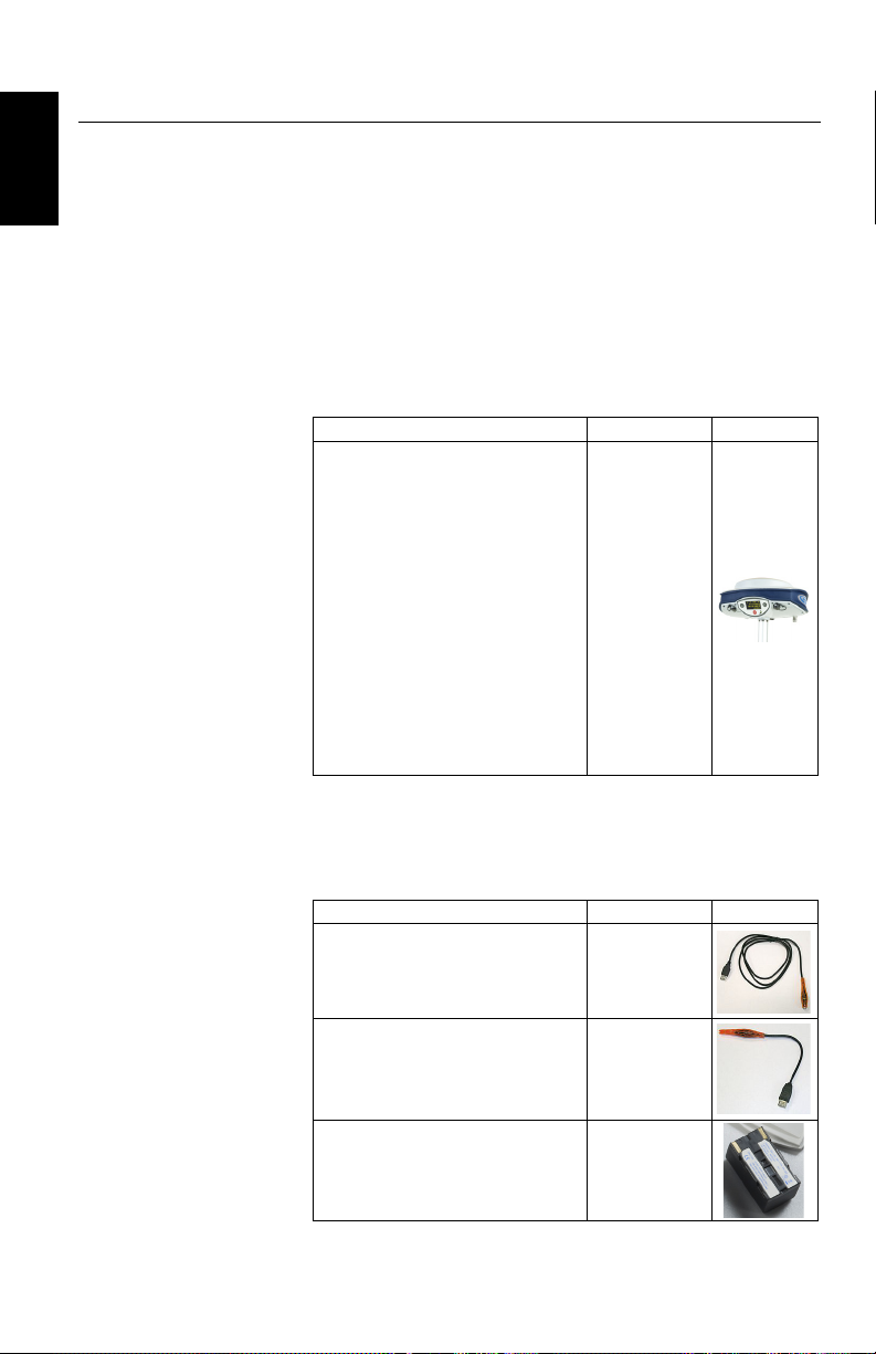
Item Part Number Picture
ProMark 800 GNSS receiver with standard accessories:
• 1x Li-ion rechargeable battery pack
• AC/DC power supply kit
• HI measurement tool
• USB cable, host
• USB cable, device
• GSM antenna
• GPS antenna extension
• Transport bag
• GNSS Solutions (RTK+L1 post-processing)
• Firmware options: Unlimited RTK,
GLONASS, GALILEO, GSM Modem,
20- Hz Fast Output
990657-99
Standard
Accessories
(Can be ordered separately as spare parts.)
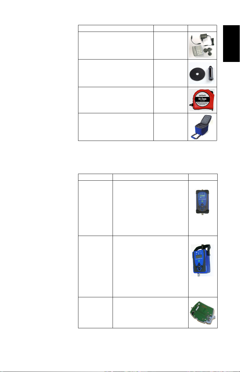
Item Part Number Picture
USB Device to PC Cable (long)
USB Host to Device Cable (short). 702104
7.4 V-4.6 Ah Li-ion Battery
Pack (rechargeable)
702103
111374
2
Page 7
Communication
Modules and
Associated
Antennas
Item Part Number Picture
AC/DC Power Supply Kit (includes external AC adapter, battery charger and
cable extension for powering ProMark
800 directly from the AC adapter)
Vertical Antenna Extension 103717
HI Measurement Tool 111146-1
Field bag 206490-ASH
Item Part Number Picture
87330-00: ADL Vantage Kit, 430-470
MHz, 4 W
87330-20: Accessory kit, 430-450 MHz
87330-10: Accessory kit, 450-470 MHz
ADL Vantage
ADL Vantage Pro
Radio receiver kit
(includes radio
module, whip
antenna and
small parts)
Each accessory kit includes a unity-gain
antenna, a range pole mount, a tripod
mount system, a battery accessory kit
(without the battery) and a Vantage/Vantage Pro programming cable.
87400-00: ADL Vantage Pro Kit, 430-470
MHz, 35 W
87400-20: Accessory kit, 430-450 MHz
87400-10: Accessory kit, 450-470 MHz
Each accessory kit includes a unity-gain
antenna, a range pole mount, a tripod
mount system, a 35-W radio battery bag
with 2 x 6’ cables (without the battery) and
a Vantage/Vantage Pro programming
cable.
PacCrest:
802149-30 (430-450 MHz, 12.5 kHz or
25 kHz)
802149-50 (450-470 MHz, 12.5 kHz or
25 kHz)
802064
English
Transmitter
alone
Transmitter
alone
3
Page 8

English
Base Accessories
Item Part Number Picture
Quad-band GSM
antenna
Power cable kit 802143
111397
Item Part Number Picture
ADL Vantage (Pro) to ProMark 800 cable
(PacCrest ref. A00630)
105659
4
Page 9
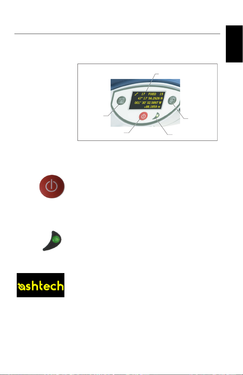
Equipment Description & Basic Functions
Power Button
Log Button
Scroll Button
Power LED
Display Screen
Front Panel View
Indicators &
Controls
English
Power button
To turn on the ProMark 800, hold the Power button pressed
until the power LED lights up.
To turn off the ProMark 800, hold the Power button pressed
until the “Ashtech” screen is displayed. Then release the
button and wait until the ProMark 800 shuts down.
Power LED
This indicator is on when the ProMark 800 is on, and off
when it is off.
Display Screen
The display consists of a 128 x 64-pixel, 1.5-inch
monochrome yellow screen using organic LED technology
(OLED). It is oriented slightly downwards so the screen can
easily be read when the ProMark 800 is installed on top of a
range pole.
Used in conjunction with the Scroll button, the display screen
allows you to view different pages of information. See Display
Screens on page 10 for a detailed description of the
information available from this screen.
5
Page 10

English
After a few seconds of inactivity (i.e. Scroll button idle),
screen luminosity turns from high to low level.
Scroll button
Press this button shortly to scroll through the different pages
of information viewed on the screen.
If an alarm is reported on the display screen, a short press on
the Scroll button will acknowledge the alarm. The Scroll
button will recover its display scrolling function only after all
the alarms have been acknowledged this way.
Another function of the Scroll button is to re-activate the
screen backlight after the latter has automatically been
turned off. The Scroll button is also used in the firmware
update procedure.
Log Button
Press this button briefly to start recording raw data on the
selected storage medium.
Another short press on this button will immediately stop raw
data recording.
Buzzer
The internal buzzer will sound an alarm whenever a warning
message is reported on the screen. The buzzer will beep until
you acknowledge the warning message by pressing the Scroll
button.
6
Bottom View
Radio Antenna
5/8” adaptor
Radio module
RS232/422 port
(port A)
Front Panel
USB Port
GSM Antenna
Battery
Compartment
Bluetooth (port C)
DC Power Input
Page 11

Battery,
Connectors &
Module
Battery Model & Battery Compartment
English
The battery used in the ProMark 800 is a 7.4-V DC - 4600
mAh rechargeable battery. It is a standard model used in
many camcorders.
The battery is housed in a battery compartment accessible
from underneath the ProMark 800. The compartment door
can be removed using a coin to release the two quarter-turn
screws.
DC Power Input
A three-contact, female connector (Fischer type) allowing the
ProMark 800 to be powered from either the provided AC
adapter (connect the cable extension between ProMark 800
and the end of the AC adapter output cable), or an external
9- to 28-V DC battery through cable P/N 730477 (cf. base
configuration with radio).
GSM Antenna
A coaxial female connector (SMA type) allowing you to
connect a GSM whip antenna to the ProMark 800.
Radio Antenna
A coaxial female connector (TNC type) allowing you to
connect a radio whip antenna to the ProMark 800. This
connector is available only if the ProMark 800 has been fitted
with a radio module.
Radio Module
A module allowing ProMark 800 to receive and process
corrections from a base. When a radio module is used, a radio
antenna must be connected (see above). When no radio
receiver kit is delivered, a single compartment door is
provided instead, with no connector on it.
7
Page 12

English
USB Port
A nine-contact female connector (Fischer type). Depending
on how it is configured, the USB port can be used in two
different ways:
1. For a USB host such as a mass storage device. In this
case, you should use the special adaptor cable provided
(P/N 702103) to attach the USB key to the ProMark 800.
This configuration can be used to log raw data on the USB
key or upgrade the ProMark 800 firmware from the files
stored on the key.
2. For a USB device allowing ProMark 800 to be seen as a
disk from the computer connected to this port. In this
configuration, files can be transferred between the
ProMark 800’s internal memory and the computer using
the USB cable provided (P/N 702104).
RS232/422 Serial Port
A seven-contact female connector (Fischer type) allowing you
to connect the ProMark 800 to an external device via an
RS232 or RS422 serial line (default: RS232), as explained
in the ProMark 800 Reference Manual.
Bluetooth Device
An integrated Bluetooth module allowing the ProMark 800 to
communicate with a Bluetooth-enabled field terminal
through a wireless connection.
8
Page 13

Antenna
100.1 mm
104.0 mm
L1
L2
Antenna Radius
= 98 mm
SHMP Offset
=40 mm
Height Mark
Characteristics
The diagram below gives the dimensional parameters of the
ProMark 800 antenna required for the system to determine
the true height of the antenna from the measured value
obtained using one of the standard height measurement
methods, i.e. slant or vertical.
The height mark allows you to hook the measure tape onto it
so you can unroll the tape down to the survey mark and read
the slant height measurement directly on the tape.
English
Special Button
Combinations
• With the ProMark 800 OFF, pressing the Power, Log and
Scroll buttons simultaneously for a few seconds will
restore all the factory settings. Always use this
combination after changing the radio module. This allows
the receiver to recognize the new module.
• With the ProMark 800 OFF and a USB key connected,
pressing the Power and Scroll buttons simultaneously for
a few seconds will cause the ProMark 800 to start a
firmware upload process. If there is no USB key
connected or the key does not contain a firmware upgrade,
then the process will abort after a few seconds.
Because data has to be decompressed on the USB key
during upgrades, the USB key must be unlocked, with at
least 10 MBytes of free memory, before starting the
upgrade.
These button combinations are summarized in the table
below:
Button
Combination
Power+Log+Scroll OFF Restores Factory Settings.
Power+Scroll OFF Initiates firmware update from USB key.
ProMark 800
State
Function
9
Page 14

Display Screens
English
Power-On Screen When you power on the receiver, the Ashtech logo appears on
If you press the Scroll button several times, you will see the
following displays successively.
the screen. It is displayed until the receiver has completed its
auto-test (this takes about 30 seconds).
Then the General Status screen is displayed.
General Status
Screen
An example of General Status screen is shown below.
[1]
[2] [3] [4]
[5]
[6]
[9] [10] [11] [12] [13]
This screen displays the following information:
• : Satellite icon [1] (always displayed).
• Number of satellites tracked [2].
• Position solution status [3]:
– NONE: Position not available
– AUTO: Autonomous GPS position
– DGPS: Differential GPS position
– S DGPS: SBAS Differential GPS position
– FLOAT: Float solution
– FIXED: Fixed solution (RTK is operational)
– BASE: Receiver configured as a base.
[8]
[7]
10
Page 15
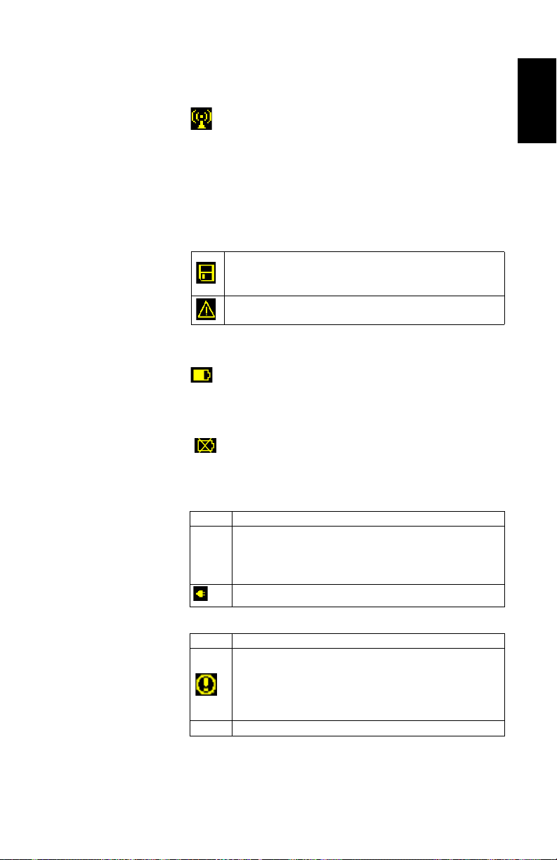
• Number of satellites used [4]: Number of satellites used
in the position processing, regardless of the current
position solution status.
• : Data link icon [5]. This icon is displayed only when
corrections are received.
• Age of corrections [6], in seconds. This value is displayed
when corrections are received and only after base station
information has been received (Position status is at least
“DGPS”).
• Raw data logging icon [7]:
Data recording through front panel Log button:
– Blinking: Raw data logging in progress
– Fixed: No raw data logging in progress.
ATL data recording for advanced diagnosis.
• Percentage of free memory in the storage medium used
[8].
• : Battery icon [9] with visual indication of remaining
charge. If an external power source is used (AC adapter or
external battery), the battery icon will be animated to
indicate battery charging in progress.
is displayed when there is no battery in the
compartment and the receiver is operated from an
external power source.
• Power status [10].
Icon Definition
Percentage of remaining battery. This indication will flash when
Percent
value
the remaining energy drops below 5%. When an internal battery is
used with external power applied, this icon alternates between the
plug and the percentage of charge on the battery.
Replaces percentage when an external power source is used.
English
• Alarm status [11].
Icon Definition
Alarm detected. Press the Scroll button to view the alarm type.
Press it again to acknowledge the alarm, which then disappears
from the list. Unless there is another alarm in the queue, in which
case you will have to resume the acknowledge sequence, the
screen then displays the memory screen.
None No alarm detected
11
Page 16
English
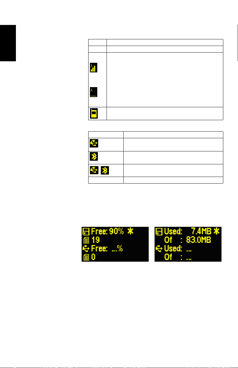
• GSM module (modem) status [12]. This may be one of the
following icons:
Icon Definition
Blank Modem turned off.
Blinking icon: Modem turned on but not initialized yet. Indicates
signal strength at modem antenna input.
Fixed icon: Modem turned on and initialized (ready for a connection). Indicates signal strength received at modem antenna input.
The higher the number of bars, the better the signal.
This icon will show four dots at the bottom when the input signal is
zero.
The symbol shown in the upper left corner stands for “2G”. When
the modem detects a 3G network, “3G” is displayed instead.
Modem on line.
•[13]: USB status and/or Bluetooth status.
Icon Definition
USB port connected to active device
Bluetooth active
/
Blank USB port unconnected and Bluetooth inactive.
These two icons will appear successively when both the
USB port and Bluetooth are active.
Memory Screens From the General Status screen, press the Scroll button to
access the Memory screens. Memory screens appear
successively (see examples) at a display rate of about five
seconds:
12
Left screen:
• First line: Percentage of free space in the internal
memory.
• Second line: Number of files currently stored in the
internal memory.
• Third line: Percentage of free space on the USB mass
storage device.
• Fourth line: Number of files currently stored on the USB
mass storage device.
Page 17
Right screen:
• First line: Total space occupied by the files currently
stored in the internal memory.
• Second line: Nominal size of the internal memory.
• Third line: Total space occupied by the files currently
stored on the USB mass storage device.
• Fourth line: Nominal size of the USB mass storage device.
About the “*” symbol:
• It can only appear at the end of the first or third line.
• Where placed, it indicates that this storage medium is
used for data logging.
What if there is no USB mass storage device connected to the
receiver?
• Parameters relevant to the USB key size and space used
and available are void (three dots displayed instead).
• Number of files is forced to “0”.
English
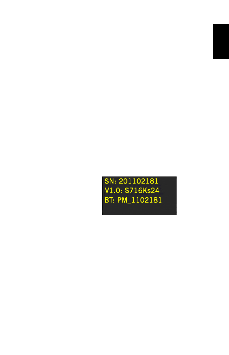
Receiver
Identification
Screen
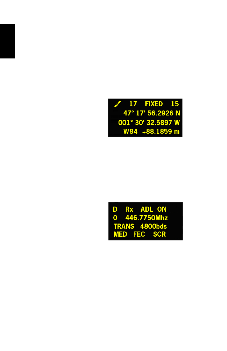
Position
Computation
Screen
From any of the two Memory screens, press the Scroll button
to access the Receiver Identification screen. See example
below.
• Receiver Serial Number
• Firmware Version
• Receiver Bluetooth Identifier
From the Receiver Identification screen, press the Scroll
button to access the Position Computation screen. This
screen displays the receiver position. The displayed
coordinates will be:
• either WGS84 coordinates (“W84” displayed at the
beginning of the last line; coordinates are latitude,
longitude and ellipsoidal elevation)
• or local coordinates (“LOC” displayed at the beginning of
the last line; coordinates may be either Easting, Northing,
Height or Latitude, Longitude, Ellipsoidal Elevation,
13
Page 18
English
depending on whether or not a projection is defined in the
local coordinate system used),
If the receiver is a rover, the displayed position will be the last
computed position. The coordinates will be local (“LOC”)
only if the rover receives specific RTCM messages from the
base describing the local system used by the base.
If the receiver is a base, the displayed coordinates are set
ones (not computed ones) representing the WGS84 or local
reference position assigned to the base. See screen example
below for a rover delivering WGS84 coordinates.
The upper line contains the same information as in the upper
line of the General Status screen.
A new press on the Scroll button will take you to the ATL
Recording screen (see below). If however the receiver is fitted
with a radio receiver or is connected to an external radio
transmitter, an additional display screen will show up before
pressing the Scroll button takes you back to the ATL
Recording screen.
14
The possible two screens show the current radio settings:
• First line: Serial port used, “Rx” for radio receiver or “Tx”
for radio transmitter, radio type (ADL). Extra-parameter for
“Rx”: Power status
• Second line: Channel number, carrier frequency
• Third line: Protocol used (Transparent, Trimtalk, DSNP,
etc.), airlink speed
• Fourth line: Squelch setting (medium, low, high). Extra-
parameters for Rx if a Pacific Crest: “FEC” if forward error
correction enabled, “SCR” if scrambling enabled.
Modulation type (GMSK, 4FSK). The fourth line will be
Page 19

slowly scrolled to the right if four parameters have to be
displayed in the line.
ATL Recording
Screen
Pressing the Scroll button from the Position Computation
screen –or from the Radio Settings screen if there is a radio
used– will take you to the ATL Recording screen, which looks
like one of the following, depending on whether a USB key is
connected to the receiver (below, right) or not (below, left).
You don’t normally have to record ATL data, but if for
troubleshooting purposes, the Technical Support asks you to
do so, then proceed as follows:
• Press the Log button (left-hand button). This will cause
the receiver to start recording ATL data on the specified
storage medium. The screen will then look like this:
You can then freely use the Scroll button to access other
receiver screens without affecting the ATL data collection
in progress (pressing the Scroll button from this screen
will take you back to the General Status screen).
• When enough ATL data have been recorded (Tech Support
will usually indicate the duration of ATL data collection
needed for troubleshooting), then come back to the ATL
Recording screen and simply press on the Log button
again to stop the recording.
NOTE 1: ATL data recording is totally independent of raw
data recording: controlling ATL recording is done exclusively
from the ATL recording screen, and raw data recording from
any other screen.
NOTE 2: Before connecting a USB key to record ATL data,
make sure there is no *.par files saved on the key as the
presence of this type of file would initiate some other
functions in the receiver.
English
15
Page 20

English
Clean up
internal
memory?
Delete
all G-les?
Delete
all les?
Forma t
memory?
Yes Yes YesNo
No
Yes No
No
Back to General Status Screen
ATL Recording Screen
Scroll button
Conrm?
Yes
No
In progress...
Memory
Management
Screen
From the ATL Recording screen, press the Scroll button to
access the Memory Management screen. The flowchart
below summarizes the different tasks you can perform at this
point in the management of the receiver memory.
Screen Backlight The screen backlight is automatically turned off if no key is
pressed for 1 minute. When the backlight is off, a short press
on the Scroll button will turn it back on. The Scroll button will
then recover its usual functions.
16
Data Transfer
Screen
or more information on the screen displayed when
F
downloading files, refer to Downloading Raw Data
on page 21.
Page 21

Charging Batteries Before Use
Make sure the battery is fully charged for each ProMark 800
you will be using in the field. Follow the instructions below to
charge a battery.
English
Removing the
Battery from the
ProMark 800
Charging the
Battery
Unless the battery has already been taken out, do the
following:
• Put the ProMark 800 upside down.
• Remove the battery door, accessible from underneath the
ProMark 800, by loosening the two quarter-turn screws
(see picture) using a coin.
• Keeping one hand on the battery still in its compartment,
put the ProMark 800 the right way up. The battery will
then easily slide out of the battery compartment.
The battery charger comes with a separate universal AC
adapter fitted with a 1.5-m output cable. The AC adapter
includes a choice of four different, detachable plug types.
Follow the instructions below to operate the charger.
• Choose the plug type that is suitable for your country.
• Secure that plug on the AC adapter by giving the plug the
right orientation with respect to the adapter, then pushing
and rotating it by about 10 degrees clockwise until you
hear a “click”.
• Connect the cable from the AC adapter to the battery
charger.
• Give the battery the right orientation with respect to the
charger [1] (the battery terminals should come into
contact with the two sets of connectors on the charger),
17
Page 22

English
[1] [2]
11
2
MED MAXHI
MED
MAXHI
[3]
[6]
MED MAXHI
[5]
MED MAXHI
[4]
then push the battery against the plate and slide it forward
[2] until it locks into place.
• Plug the adapter into an AC outlet. Battery charging starts
immediately.
For a low battery that’s being charged, you will first see the
three LEDs switch on and off, one after the other, followed
by a short period of time when none of the LEDs is on (see
[3]).
After about two hours of charging, the MED LED will stay
on [4]. A few minutes later, the HI LED [5], and then the
MAX LED [6] will also stay on.
• When the three LEDs are on, this means the battery is
fully charged and can be disconnected from the charger.
Inserting the Battery in the ProMark 800
18
• With the ProMark 800 upside down, insert the battery into
the compartment making sure the battery has the right
orientation (the battery terminals should come into
contact with the two sets of connectors located at the
bottom of the compartment).
• Place the battery door over the battery and tighten the two
screws, using a coin. Note that, once it is properly
secured, the battery door pushes the battery against the
bottom of the compartment to ensure electrical
connection of the battery to the ProMark 800.
Page 23

RTK Base Setup
• You will need a tripod and a tribrach (not provided) to
install the base. The provided antenna extension pole
fitted with a 5/8” male adapter is also required in this
configuration.
• For a long-range radio link, i.e. more than 1 mile or 1.6
km, for which the radio antenna should be placed as high
as possible, it is good practice to install the antenna on
top of an antenna pole secured on a tripod (neither of
these items is provided).
• To power the radio, you need an external 9-16 V DC power
source. Using a standard 12-V DC battery is a convenient
choice. In this configuration, the ProMark 800 can be
powered either from the same power source
(recommended), using cable P/N 802143, or from its
internal battery.
Powering the ProMark 800 from the external battery offers
two advantages:
1. Operating sessions can be extended significantly.
2. The external battery operates as a trickle charger for
the ProMark 800’s internal battery.
The connection diagram is as follows.
English
ProMark 800 Base
Power
Cable Kit P/N 802143
RS (Port A)
ADL Vantage
or ADL Vantage Pro
Transmitter
Pacific Crest Data/Power Cable (A00630)
SAE
Fuse (4 A)
+
External 9-16 V
DC Power Source
Radio Antenna
19
Page 24

RTK Rover Setup
[1]
[2]
[3]
[4]
English
Prerequisites
Radio Link
[1]
[2]
[3]
[4]
• Use a range pole fitted with a 5/8” male adaptor at the
upper end (not provided).
• If a radio link is used with the base, your rover should
normally have been fitted with the radio module that
matches the reception band covered by the radio
transmitter used at the base.
• If a GPRS connection is used, your rover should normally
have been fitted with the SIM card that will allow it to
perform a network connection.
To connect the SIM card, first use a flat screwdriver to
loosen the two quarter-turn screws securing the radio
module. Remove the module. This gives access to an
electronic card on which you can insert the SIM card as
shown on the picture.
Mount the different items as shown on the picture, including
the ProMark 800 [1], the radio antenna [2], the range pole
[3] and the field terminal with its mounting bracket [4].
Caution! Use of a non-metal range pole is recommended to
maintain the performance level of the radio antenna.
20
GSM/GPRS
Connection
As a standard feature, the ProMark 800 incorporates a builtin GSM modem, which means you only have to connect the
GSM antenna if you have paid for activation of the hardware.
Mount the different items as shown on the picture, including
the ProMark 800 [1], the GSM antenna [2], the range pole
[3] and the field terminal with its mounting bracket [4].
Caution! Use of a non-metal range pole is recommended to
maintain the performance level of the GSM antenna.
Page 25

Logging Raw Data
Starting/Stopping
Raw Data Logging
Downloading Raw
Data
You simply need to use the Log button to start and stop raw
data logging. Later, you will however need to do the following
manually:
1. Downloading phase (if appropriate, rename the raw data
files collected on each site).
2. Post-processing phase: Manually correct all computed
elevations for the antenna height.
By default, raw data is logged to the receiver’s internal
memory. The Raw Data Logging icon on the General Status
screen will start flashing when a raw data file is open for
logging.
Use a USB mass storage device as a transit storage medium
to download raw data files from the receiver’s internal
memory to your office computer.
Important! During a download operation, files are not deleted
from the receiver but simply copied to the USB mass storage
device.
After downloading the files to this device, connect the USB
device to your computer and use your usual browser to copy
the files to the project folder.
Using a USB Mass Storage Device
• Connect the USB mass storage device to the receiver via
the short USB Host-to-Device cable provided (P/N
702104).
If raw data files are present in the receiver’s internal
memory, the following icons will automatically appear on
the display screen:
English
• To confirm the file transfer, press the Log button. The
General status screen will re-appear after the file transfer
is complete.
• To cancel the file transfer, press the Scroll button.
21
Page 26

English
• If you do not press any button within the next 10 seconds,
the download procedure will be canceled automatically
and the screen will come back to the previous display.
Using the USB Cable Provided
• Connect the USB cable provided (P/N 702103) between
the office computer and the receiver’s USB port. The
receiver is then seen as a USB device from the office
computer
• Using Windows Explorer on your office computer, browse
the receiver’s internal memory for the raw data files.
• Copy/paste the files to your project folder.
22
Page 27

Index
A
AC/DC power supply kit 3
Alarm status 11
Alarms 6
Antenna characteristics 9
Antenna extension 3
AUTO 10
B
Backlight 6
BASE 10
Battery (external) 19
Battery (insert) 18
Battery (remove) 17
Battery charger 3
Battery icon 11
Battery model 7
BLADE 1
Bluetooth 8
Bluetooth identifier 13
Bluetooth status 12
Buzzer 6
C
Charging battery 17
D
Data link icon 11
Data transfer screen 16, 21
DC power input 7
Device cable (USB) 2, 21
Display screen 5
F
Factory settings 9
FAST Survey 1
Field bag 3
Field terminal 20
Firmware update 9
Firmware version 13
FIXED 10
FLOAT 10
G
General Status screen 10, 21
GLONASS 1
GPRS 20
GSM antenna 4, 7, 20
GSM module (built-in) 20
GSM status 12
H
Height mark 9
HI measurement tape 3, 9
Host cable (USB) 2
K
Key combinations 9
Kinematic 1
L
L1 phase center 9
L2 phase center 9
LED status (battery charger) 18
Li-ion battery 2
Log button 6
Long-range radio link 19
M
Memory screens 12
O
OLED 5
P
PacCrest transmitter (connection diagram)
19
Pages (of information) 6
Position computation screen 13
Post-processed surveys 1
Power button 5
Power LED 5
Power status 11
Power-on screen 10
R
Radio antenna 7, 20
Radio module 7, 20
Radio receiver kit 3
Radio transmitter (#800986) 19
Range pole 20
Raw data 6
Raw data icon 11
Receiver identification screen 13
Receiver serial number 13
S
Satellites in use 11
SBAS 1
Screen backlight 16
Scroll button 5, 6, 10
Serial port 8
SIM card 20
Slant measurement 9
Standalone (raw data logging) 21
Status (position) 10
Stop&Go 1
T
Tribrach 19
Tripod 19
English
Page 28

English
U
USB port 8
USB status 12
Page 29

Page 30

ProMark™ 800
Getting Started Guide
Contact Information:
SPECTRA PRECISION DIVISION
10355 Westmoor Drive,
Suite #100
Westminster, CO 80021, USA
www.spectraprecision.com
©2011-2013 Trimble Navigation Limited. All rights reserved. Spectra Precision is a Division of Trimble Navigation Limited. Spectra Precision and the
Spectra Precision logo are trademarks of Trimble Navigation Limited or its subsidiaries. P/N 631667-01 B
Rue Thomas Edison
ZAC de la Fleuriaye, BP 60433
44474 Carquefou Cedex, FRANCE
 Loading...