

Page 1

MobileMapper Field & Ofce Software
Getting Started Guide
Page 2

SOFTWARE END USER LICENSE AGREEMENT (EULA)
IMPORTANT, READ THIS AGREEMENT CAREFULLY. BY INSTALLING OR USING ALL OR ANY PORTION OF THE SOFTWARE, YOU ARE ACCEPTING
ALL OF THE TERMS AND CONDITIONS OF THIS
AGREEMENT. YOU AGREE THAT THIS AGREEMENT IS ENFORCEABLE LIKE ANY WRITTEN
AGREEMENT.
IF YOU DO NOT AGREE TO ALL OF THESE TERMS
AND CONDITIONS, DO NOT USE OR ACCESS THE
SOFTWARE.
IF YOU HAVE PAID A LICENSE FEE FOR USE OF
THE SOFTWARE AND DO NOT AGREE TO THESE
TERMS, YOU MAY RETURN THE SOFTWARE
(ALONG WITH ANY HARDWARE ON WHICH IT
WAS EMBEDDED, IF APPLICABLE) FOR A FULL
REFUND PROVIDED YOU (A) DO NOT USE THE
SOFTWARE AND (B) RETURN THE SOFTWARE
WITHIN THIRTY (30) DAYS OF YOUR INITIAL PURCHASE.
IF YOU WISH TO USE THE SOFTWARE AS AN EMPLOYEE, CONTRACTOR, OR AGENT OF A CORPORATION, PARTNERSHIP OR SIMILAR ENTITY,
THEN YOU MUST BE AUTHORIZED TO SIGN FOR
AND BIND THE ENTITY IN ORDER TO ACCEPT THE
TERMS OF THIS AGREEMENT. THE LICENSES
GRANTED UNDER THIS AGREEMENT ARE EXPRESSLY CONDITIONED UPON ACCEPTANCE BY
SUCH AUTHORIZED PERSONNEL.
IF YOU HAVE ENTERED INTO A SEPARATE WRITTEN LICENSE AGREEMENT WITH TRIMBLE FOR
USE OF THE SOFTWARE, THE TERMS AND CONDITIONS OF SUCH OTHER AGREEMENT SHALL PREVAIL OVER ANY CONFLICTING TERMS OR
CONDITIONS IN THIS AGREEMENT.
This End User License Agreement (“Agreement”) is
between Trimble Navigation Limited, located at 935
Stewart Drive, Sunnyvale, CA 94085, U.S.A. and/or
its Affiliates (“Tri mbl e”) and the customer (individual or entity) that has downloaded or otherwise procured the licensed Software (as defined below) for
use as an end user (“You ”). This Agreement covers
any Software and supporting technical documentation provided with the Software (“Documentation”).
1. Definitions
“Affiliate” shall mean any entity that directly or indirectly through one or more entities, controls, is controlled by, or is under common control with a Trimble
party. For purposes of this definition, the term "con-
trol" as applied to any entity, means the possession,
directly or indirectly, of the power to direct or cause
the direction of the management of that entity,
whether through ownership of voting securities or
otherwise.
“Effective Date” means the earlier of the date You
sign an Order Form or the date on which the Software
is first made available to You.
“Order Form” means any order which is entered into
by Trimble (or an authorized Trimble distributor or reseller) and You under which You are provided the
Software. Each Order Form for the Software shall be
deemed a part of this Agreement. This Agreement is
binding on You whether or not You executed an Order
Form with Trimble. Order Forms may not vary the
terms of this Agreement. Only a written agreement,
signed by Trimble (not a Trimble distributor or reseller) may vary the terms of this Agreement.
(TNL - TEBV)
“Software” means the Trimble software product(s)
provided in connection with this Agreement in object
code form (or as otherwise specified in any related
Order Form). “Software” shall also include any releases provided to or purchased by You under any
separate support and maintenance agreement You
may enter into with Trimble. Unless otherwise noted,
the Software and Documentation are referred to collectively herein as “Software”.
“Third-Party Software” means any third-party software that is provided to You by Trimble under this
Agreement or under separate terms and conditions.
“Trimble Supplier” means either Trimble or an authorized distributor or reseller of Trimble products or services which has entered into an Order Form with You.
2. License
2.1.Grant of License. Subject to all of the terms and
conditions of this Agreement, Trimble grants You a
non-transferable, non-sublicensable, non-exclusive
license to use the Software in machine-readable form
on any computer and operating system for which it
was intended, but solely (a) for your own internal
business purposes at the location specified in the applicable Order Form or otherwise agreed to by Trimble
(the “Site”); (b) in accordance with the Documentation; and (c) in accordance with any additional license term, subscription term or other user, seat,
computer, field of use or other restrictions set forth
in the applicable Order Form or otherwise specified
by Trimble.
2.2.Installation and Copies. Trimble shall make
available the Software and Documentation by disk,
other media, or as embedded in a device, or make it
available for download in electronic form. Trimble
shall also provide You with electronic passwords or
other enabling mechanisms if necessary to permit
the licensed usage of the Software. All licenses shall
commence, and delivery shall be deemed to occur, as
of the Effective Date (or, if later, such date on which
the Software and license keys are first made available to You). If your Order Form is with a Trimble distributor or reseller, that distributor or reseller (and
not Trimble) is solely responsible for delivery to You
and Trimble has no liability for any failure to deliver.
If the Software requires license keys to operate as licensed to You, the applicable Trimble Supplier will
deliver such license keys to You.
2.3.Software Intended to be Installed on Computers.
The Software is licensed as a single product. You may
not separate its component parts for use on more
than one computer except as specifically authorized
in this Agreement. You may copy and install on your
computers for use only by your employees the number of copies of the Software for which You have paid
the applicable license fee or have been authorized in
writing by Trimble. You may transfer the Software
from one computer to another computer provided
that the computer to which the Software is transferred is located at the Site and the Software is completely removed and de-installed from the prior
computer. If You are permitted by Trimble to install
the Software on a network server, and You transfer
the Software from the Site to a new location, You
must provide Trimble with written notice of the new
site prior to such transfer. You may also make a reasonable number of copies of the Software only for
back-up and archival purposes. This Paragraph 2.3
does not apply to any software embedded on Trimble
devices.
Page 3

2.4. License Restrictions.
2.4.1 You shall not (and shall not allow any third party to): (a) decompile, disassemble or otherwise reverse engineer the Software or attempt to reconstruct
or discover any source code, underlying ideas, algorithms, file formats or programming interfaces of the
Software by any means whatsoever (except and only
to the extent that applicable law prohibits or restricts
reverse engineering restrictions). To the extent any
applicable mandatory laws give You the right to perform any of the aforementioned activities without
Trimble’s consent in order to gain certain information
about the Software for purposes specified in the respective statutes (e.g., interoperability), You hereby
agree that, before exercising any such rights, You
shall first request such information from Trimble in
writing detailing the purpose for which You need the
information. Only if and after Trimble, at its sole discretion, partly or completely denies your request,
may You exercise such statutory rights; (b) distribute,
sell, sublicense, rent, lease or transfer the Software
(or any portion thereof), nor use the Software (or any
portion thereof) for time sharing, hosting, service
provider or like purposes; (c) provide the Software to
a third party on a temporary basis and/or use the
Software for the benefit or purposes of a third party
whether by means of lease, loan, data processing services (e.g. “fee for service”) or otherwise, unless You
are a reseller of Trimble products under separate written agreement with Trimble and authorized by Trimble to do so; (d) remove any product identification,
proprietary, copyright, or other notices contained in
the Software; (e) modify any part of the Software,
create a derivative work of any part of the Software,
or incorporate the Software into or with other software, except to the extent expressly authorized in
writing by Trimble; (f) attempt to circumvent or d isable the security key mechanism that protects the
Software against unauthorized use (except and only
to the extent that applicable law prohibits or restricts
such restrictions) and/or any licensing control features; or (g) publicly disseminate performance information or analysis (including, without limitation,
benchmarks or comparison testing or analysis) from
any source relating to the Software or disclose to any
third-party or release any results thereof (all of which
information shall be considered Trimble confidential
information) without Trimble’s prior written consent.
2.4.2 If the Software has been provided to You as
embedded in any hardware device, You are not licensed to separate the Software from the hardware
device. If the Software has been provided to You separately from a hardware device but is intended to be
loaded onto a hardware device specified by Trimble
(such as a firmware update), your license is limited
to loading the Software on the device specified by
Trimble in the Documentation, and for no other use.
2.4.3 You agree to use all reasonable efforts to prevent unauthorized use and disclosure of the Software.
2.5.Evaluation Software. Subject to the terms and
conditions of this Agreement and during its term,
Trimble may, in its discretion, provide You with prerelease, beta or other software on an evaluation basis
(“Evaluation Software”). You may use Evaluation
Software solely for internal evaluation purposes for
thirty (30) days from receipt of the Evaluation Software (unless otherwise agreed by Trimble in writing)
(the “Evaluation Period”).
Unless You pay the applicable license fee for the
Software, the Evaluation Software may become inoperable and, in any event, your right to use the Evalu-
ation Software automatically expires at the end of the
Evaluation Period. Evaluation Software shall be subject to all restrictions on Software set forth in this
Agreement. You shall treat all Evaluation Software as
Confidential Information of Trimble and shall return
or destroy any copies of Evaluation Software upon expiration of the applicable Evaluation Period. Any and
all suggestions, reports, ideas for improvement and
other feedback of any type You provide regarding the
Evaluation Software are the sole property of Trimble,
and Trimble may use such information in connection
with any of its products or services without any obligation or restriction based on intellectual property
rights or otherwise. You acknowledge that all Evaluation Software is provided “AS IS” and may not be
functional on any machine or in any environment.
THE WARRANTIES OF SECTION 5 DO NOT APPLY
TO EVALUATION SOFTWARE. TRIMBLE AND ITS
SUPPLIERS DISCLAIM ALL WARRANTIES RELATING TO THE EVALUATION SOFTWARE, EXPRESS
OR IMPLIED, INCLUDING, BUT NOT LIMITED TO,
MERCHANTABILITY, FITNESS FOR A PARTICULAR
PURPOSE, TITLE OR NON-INFRINGEMENT.
2.6.Internet-Based Services Components. Some features of the Software may require connection to the
Internet directly or through a wireless connection in
order to function. Such features may result in the
transfer of certain data over such connections, which
may or may not be secure or encrypted. You are solely
responsible for obtaining any necessary Internet
wireless subscription plans with the applicable service providers. You further acknowledge that Trimble
is not responsible for the availability of Internet or
wireless connections or the security or integrity of
data transmitted over such connections.
2.7 Ownership. Notwithstanding anything to the contrary contained herein, except for the limited license
rights expressly provided herein, Trimble, its licensors and suppliers have and will retain all rights, title
and interest (including, without limitation, all patent,
copyright, trademark, trade secret and other intellectual property rights) in and to the Software and all
copies, modifications and derivative works thereof
(including any changes which incorporate any of your
ideas, feedback or suggestions). You acknowledge
that You are obtaining only a limited license right to
the Software and that irrespective of any use of the
words “purchase”, “sale” or like terms hereunder no
ownership rights are being conveyed to you under
this Agreement or otherwise.
2.8 Copyright. All title, rights and copyrights in and
to the Software (including, but not limited to, any images, photographs, animations, video, audio, music,
and text incorporated into the Software, as well as all
intellectual property rights), the Documentation and
other accompanying written materials, and any copies of the Software are owned by Trimble, its licensors and/or suppliers. You shall not remove, cover, or
alter any of Trimble's patent, copyright, or trademark
notices placed upon, embedded in, or displayed by
the Software or on its Documentation, packaging and
related materials.
3. Payment
3.Payment. Unless a Software has been made available by Trimble at no charge, You shall pay all fees
associated with the Software licensed and any services purchased hereunder as set forth in the applicable Order Form. All payments shall be made in the
currency specified in the applicable invoice within
thirty (30) days of your receipt of such invoice, unless otherwise specified in writing by the Trimble
Supplier. Except as expressly set forth herein, all fees
Page 4

are non-refundable once paid. You shall be responsible for all taxes, withholdings, duties and levies arising from the order (excluding taxes based on the net
income of the Trimble Supplier). Any late payments
shall be subject to a service charge equal to 1.5%
per month of the amount due or the maximum
amount allowed by law, whichever is less.
4. Term of Agreement
4.1.Term. This Agreement is effective as of the Effective Date and expires at such time as all license
and service subscriptions hereunder have expired in
accordance with their own terms (the “Ter m”). Either
party may terminate this Agreement (including all
related Order Forms) if the other party: (a) fails to
cure any material breach of this Agreement within
thirty (30) days after written notice of such breach;
(b) ceases operation without a successor; or (c) seeks
protection under any bankruptcy, receivership, trust
deed, creditors arrangement, composition or comparable proceeding, or if any such proceeding is instituted against such party and not dismissed within
sixty (60) days. If You have entered into a separate
written agreement with Trimble which governs the
Software and that agreement is terminated, then this
Agreement automatically terminates and You shall no
longer have any right to use the Software. Termination is not an exclusive remedy and the exercise by
either party of any remedy under this Agreement will
be without prejudice to any other remedies it may
have under this Agreement, by law, or otherwise. For
clarity, even if You have entered into an Order Form
with a Trimble distributor or reseller, Trimble is a
third party beneficiary to that Order F orm and has the
right to terminate this Agreement as set forth in this
Section 4 (Term of Agreement).
If a Software has been made available by Trimble at
no charge, the license remains effective until terminated in accordance with subparagraphs (b) to (c)
mentioned above; You decide to terminate this
Agreement by ceasing all use of the Software and destroying or returning all copies; or, without prejudice
as to any other rights, Trimble decides to terminate
this Agreement with or without notice if You fail to
comply with the terms and conditions of this Agreement.
4.2.Termination. Upon any expiration or termination
of this Agreement, You shall cease any and all use of
any Software and Evaluation Software and destroy all
copies thereof and so certify to Trimble in writing.
5.3.Survival. Paragraph 2.4 (License Restrictions),
Paragraph 2.7 (Ownership), Paragraph 2.8 (Copyright), Section 3 (Payment), Section 4 (Term of
Agreement), Paragraph 5.3 (Disclaimer of Warranties), Section 8 (Limitation of Remedies and Damages), Section 9 (Confidential Information), Section 10
(Export Compliance) and Section 11 (General) shall
survive any termination or expiration of this Agreement.
5. Limited Warranty and Disclaimer
6.1.Limited Warranty. Trimble warrants to You that
for a period of ninety (90) days from the Effective
Date (the “Warranty Period”) the Software shall operate in substantial conformity with the Documentation. Because the Software is inherently complex and
may not be completely free of nonconformities, defects or errors, You are advised to verify your work.
Trimble does not warrant that the Software will operate error free or uninterrupted, that it will meet your
needs or expectations, that all nonconformities can
or will be corrected, or the results obtained through
use of the Software. Trimble’s sole liability (and your
exclusive remedy) for any breach of this warranty
shall be, in Trimble’s sole discretion, to use commercially reasonable efforts to provide You with an errorcorrection or work-around which corrects the reported non-conformity, or if Trimble determines such
remedies to be impracticable within a reasonable period of time, to refund the license fee paid for the
Software. A Trimble Supplier other than Trimble may
fulfill Trimble’s warranty obligations hereunder on
behalf of Trimble. Trimble Suppliers shall have no obligation with respect to a warranty claim unless notified of such claim within the Warranty Period.
5.2.Exclusions. The above warranty shall not apply:
(a) if the Software is used with hardware or software
not specified in the Documentation; (b) if any modifications are made to the Software by You or any third
party; (c) to defects in the Software due to accident,
abuse or improper use by You; (d) to Software provided on a no charge or evaluation basis; (e) to any Third
Party Software; or (f) to any Software obtained as
freeware, whether from Trimble, a Trimble Supplier
or otherwise.
5.3.Disclaimer of Warranties. THIS SECTION 5 IS A
LIMITED WARRANTY AND, EXCEPT AS EXPRESSLY
SET FORTH IN THIS SECTION 5, THE SOFTWARE
AND ALL SERVICES ARE PROVIDED “AS IS.” NEITHER TRIMBLE NOR ITS SUPPLIERS MAKES ANY
OTHER WARRANTIES, CONDITIONS OR UNDERTAKINGS, EXPRESS OR IMPLIED, STATUTORY OR
OTHERWISE, INCLUDING BUT NOT LIMITED TO
WARRANTIES OF TITLE, MERCHANTABILITY, FITNESS FOR A PARTICULAR PURPOSE OR NONINFRINGEMENT. YOU MAY HAVE OTHER STATUTORY
RIGHTS. HOWEVER, TO THE FULL EXTENT PERMITTED BY LAW, THE DURATION OF STATUTORILY
REQUIRED WARRANTIES, IF ANY, SHALL BE LIMITED TO THE LIMITED WARRANTY PERIOD. YOU
ASSUME THE ENTIRE RISK AS TO RESULTS AND
PERFORMANCE OF THE SOFTWARE. IN ADDITION, TRIMBLE MAKES NO WARRANTY, EXPRESSED OR IMPLIED, TO SOFTWARE PROVIDED
TO YOU FREE OF CHARGE INCLUDING WITHOUT
LIMITATION FOR ACCURACY, COMPLETENESS,
SUITABILITY, PERFORMANCE OR USE. ANY SOFTWARE PROVIDED AT NO COST IS PROVIDED BY
TRIMBLE "AS IS."; ALL IMPLIED WARRANTIES ARE
IN SUCH CASE DISCLAIMED
.
6. Support & Maintenance
Trimble shall provide the support and maintenance
services, if any, as separately purchased by You and
specified in the applicable Order Form. Such support
and maintenance shall be provided pursuant to Trimble’s standard service terms which are available upon
request from Trimble. Trimble Suppliers may provide
additional support services under separate written
agreement, but Trimble is not responsible for any
such support unless being a contracting party.
7. Professional Services.
The Trimble Supplier shall provide the number of
person-days, if any, of professional consulting services (“Professional Services”) purchased in the applicable Order Form and related statement of work. If
Trimble is providing Professional Services, unless
agreed in a separate written agreement, all Professional Services shall be provided pursuant to Trimble’s standard service terms which are available upon
request from Trimble. If your Order Form is with a
Trimble Supplier other than Trimble, that party (and
not Trimble) is solely responsible for providing Pro-
Page 5

fessional Services and Trimble, not being a contracting party, has no liability related to such services.
8. Limitation of Remedies and Damages.
8.1. NEITHER TRIMBLE NOR TRIMBLE’S SUPPLIERS SHALL BE LIABLE FOR ANY LOSS OF USE,
LOST DATA, FAILURE OF SECURITY MECHANISMS, INTERRUPTION OF BUSINESS, OR ANY
INDIRECT, SPECIAL, INCIDENTAL, OR CONSEQUENTIAL DAMAGES OF ANY KIND (INCLUDING
LOST PROFITS), REGARDLESS OF THE FORM OF
ACTION, WHETHER IN CONTRACT, TORT (INCLUDING NEGLIGENCE), STRICT LIABILITY OR OTHERWISE, EVEN IF INFORMED OF THE POSSIBILITY
OF SUCH DAMAGES IN ADVANCE.
8.2. NOTWITHSTANDING ANY OTHER PROVISION
OF THIS AGREEMENT, TRIMBLE AND ITS SUPPLIERS’ ENTIRE LIABILITY TO YOU UNDER THIS
AGREEMENT SHALL NOT EXCEED THE AMOUNT
ACTUALLY PAID BY YOU TO TRIMBLE UNDER THIS
AGREEMENT.
8.3. THE SOFTWARE IS NOT FAULT TOLERANT
AND IS NOT DESIGNED, MANUFACTURED OR INTENDED FOR USE IN LIFE SUPPORT, MEDICAL,
EMERGENCY, MISSION CRITICAL OR OTHER
STRICT LIABILITY OR HAZARDOUS ACTIVITIES
(“HIGH RISK ACTIVITIES”). TRIMBLE SPECIFICALLY DISCLAIMS ANY EXPRESS OR IMPLIED WARRANTY OF FITNESS FOR HIGH RISK ACTIVITIES.
YOU REPRESENT AND WARRANT THAT YOU WILL
NOT USE THE SOFTWARE (OR PERMIT IT TO BE
USED) FOR HIGH RISK ACTIVITIES, AND AGREE
THAT TRIMBLE WILL HAVE NO LIABILITY FOR USE
OF THE SOFTWARE IN HIGH RISK ACTIVITIES.
YOU AGREE TO INDEMNIFY AND HOLD HARMLESS TRIMBLE FOR ANY DAMAGES, LIABILITIES
OR OTHER LOSSES RESULTING FROM SUCH USE.
8.4. The parties agree that the limitations specified
in this Section 8 will survive and apply even if any
limited remedy specified in this Agreement is found
to have failed of its essential purpose.
9. Confidential Information.
Any software, Documentation or technical information provided by Trimble (or its suppliers and agents)
shall be deemed “Trimble Confidential Information”
without any marking or further designation. Except as
expressly authorized herein, You will hold in confidence and not use or disclose any Trimble Confidential Information. Without limiting the foregoing, You
acknowledge that the Software constitutes the valuable confidential information and trade secrets of
Trimble and, accordingly, You shall at all times, both
during the term of this Agreement and thereafter
keep in trust and confidence all the Software, and
shall not disclose the same to any third party without
Trimble’s prior written consent. You acknowledge
that disclosure of Trimble Confidential Information
would cause substantial harm to Trimble that could
not be remedied by the payment of damages alone
and therefore that upon any such disclosure by You,
Trimble shall be entitled to appropriate equitable relief in addition to whatever remedies it might have at
law.
10. Export Compliance
You agree to comply with all applicable laws and regulations of the United States of America (“U.S.”) and
of other jurisdictions (national, state, and local) to
the extent that they may govern your use of the Software. In addition, You acknowledge that the Software
may be subject to export restrictions by the U.S. government and by certain other governments. You shall
not, and shall not allow any third party to, directly or
indirectly, remove or export or allow the export or reexport of any part of the Software or any direct product thereof: (a) into (or to a national or resident of)
any embargoed or terrorist-supporting country; (b) to
anyone on the U.S. Commerce Department’s Table of
Denial Orders or U.S. Treasury Department’s list of
Specially Designated Nationals; (c) to any country to
which such export or re-export is restricted or prohibited, or as to which the U.S. government or any agency thereof requires an export license or other
governmental approval at the time of export or re-export without first obtaining such license or approval;
or (d) otherwise in violation of any export or import restrictions, laws or regulations of any U.S. or foreign
agency or authority laws, or in violation of any applicable export control laws in the country where the
Software has been obtained or is used. You agree to
the foregoing and warrant that You are not located in,
under the control of, or a national or resident of any
such prohibited country or on any such prohibited
party list. The Software is further restricted from being used for the design or development of nuclear,
chemical, or biological weapons or missile technology, or for terrorist activity.
11. General.
11.1. Assignment. This Agreement will bind and inure to the benefit of each party’s permitted successors and assigns. Trimble may assign this Agreement
to any Affiliate or in connection with a merger, reorganization, acquisition or other transfer of all or substantially all of Trimble’s assets or voting securities.
You may not assign or transfer this Agreement, in
whole or in part, without Trimble’s written consent.
Any attempt to transfer or assign this Agreement
without such written consent will be null and void. If
You obtain such consent from Trimble, You shall permanently assign or transfer all of your rights under
this Agreement, provided You retain no copies and
You transfer all of the Software (including all component parts, the media and printed materials, any upgrades, and this Agreement), and the recipient
agrees to the terms of this Agreement. If the Software
portion is an upgrade, any assignment or transfer
must include all prior versions of the Software.
11.2. Partial Invalidity. If any provision of this Agreement is held to be invalid, illegal or unenforceable to
any extent, that provision shall, if possible, be construed as though more narrowly drawn, if a narrower
construction would avoid such invalidity, illegality or
unenforceability, or, if that is not possible, such provision shall, to the extent of such invalidity, illegality
or unenforceability, be severed, and the remaining
provisions of this Agreement shall remain in effect,
provided, however, that the court shall have authority
and jurisdiction to, and shall, add to this Agreement
a provision as similar in terms and intended to effect
to such severed provision as may be possible and be
legal, valid and enforceable.
11.3. Governing Law; Jurisdiction and Venue.
• 11.3.1. If You obtained this Software in the
U.S., this Agreement is governed by the laws of
the State of California and the U.S. without regard to conflicts of laws provisions thereof, and
without regard to the United Nations Convention
on the International Sale of Goods (“UNCISG”).
In such case the jurisdiction and venue for actions related to the subject matter hereof are the
State of California and U.S. federal courts located in Santa Clara County, California, and both
parties hereby submit to the personal jurisdiction of such courts.
Page 6

• 11.3.2. If You obtained this Software outside
the U.S., this Agreement is governed by the laws
of The Netherlands (country where Trimble Europe B.V., an Affiliate to Trimble, is located), excluding its rules governing conflicts of laws and
without regard to the UNCISG. In such case
each jurisdiction and venue for actions related
to the subject matter hereof are the Dutch
courts of the District of Oost-Brabant, The Netherlands, and both parties hereby submit to the
personal jurisdiction of such courts.
11.4. Attorneys’ Fees and Costs. The prevailing party
in any action to enforce this Agreement will be entitled to recover its attorneys’ fees and costs in connection with such action.
11.5.Notices and Reports. Any notice or report here-
under shall be in writing. If to Trimble, such notice or
report shall be sent to “Trimble Navigation Limited,
935 Stewart Drive, Sunnyvale, California 94085,
U.S.A.” to the attention of “General Counsel – Legal
Notice”. If to You, such notice or report shall be sent
to the address You provided upon placing your order
or at the time the Software has been first made available to You. Notices and reports shall be deemed given: (a) upon receipt if by personal delivery; (b) upon
receipt if sent by certified or registered U.S. mail (return receipt requested); or (c) three (3) business days
after being sent by a reputable international courier
requiring signature for receipt, addresses to the party
at its notice address. Either party may change its notice address by written notice to the other.
11.6. Amendments; Waivers. No supplement, modi-
fication, or amendment of this Agreement shall be
binding, unless executed in writing by a duly authorized representative of each party to this Agreement.
No waiver will be implied from conduct or failure to
enforce or exercise rights under this Agreement, nor
will any waiver be effective unless in a writing signed
by a duly authorized representative on behalf of the
party claimed to have waived.
11.7. Entire Agreement. This Agreement is the com-
plete and exclusive statement of the mutual understanding of the parties and supersedes and cancels
all previous written and oral agreements and communications relating to the subject matter of this Agreement. No provision of any purchase order or in any
other business form employed by You will supersede
the terms and conditions of this Agreement, and any
such document issued by a party hereto relating to
this Agreement shall be for administrative purposes
only and shall have no legal effect. Notwithstanding
the foregoing, if You have entered into a separate
written license agreement signed by Trimble for use
of the Software, the terms and conditions of such
other agreement shall prevail over any conflicting
terms or conditions in this Agreement.
11.8. Independent Contractors. The parties to this
Agreement are independent contractors. There is no
relationship of partnership, joint venture, employment, franchise or agency created hereby between
the parties. Neither party will have the power to bind
the other or incur obligations on the other party’s behalf without the other party’s prior written consent.
11.9. Force Majeure. Neither party shall be li able to
the other for any delay or failure to perform any obligation under this Agreement (except for a failure to
pay fees) if the delay or failure is due to unforeseen
events, which occur after the signing of this Agreement and which are beyond the reasonable control of
the parties, such as strikes, blockade, war, terrorism,
riots, natural disasters, refusal of license by the gov-
ernment or other governmental agencies, in so far as
such an event prevents or delays the affected party
from fulfilling its obligations and such party is not
able to prevent or remove the force majeure at reasonable cost.
11.10. Government End-Users. The Software is commercial computer software. If the user or licensee of
the Software is an agency, department, or other entity of the U.S. Government, the use, duplication, reproduction, release, modification, disclosure, or
transfer of the Software, or any related documentation of any kind, including technical data and manuals, is restricted by a license agreement or by the
terms of this Agreement in accordance with Federal
Acquisition Regulation 12.212 for civilian purposes
and Defense Federal Acquisition Regulation Supplement 227.7202 for military purposes. The Software
was developed fully at private expense. All other use
is prohibited.
11.11. Third-Party Software. If designated in the
Documentation, the Software may contain or be provided with certain Third-Party Software (including
software which may be made available to You in
source code form). Such Third-Party Software is not
licensed hereunder and is licensed pursuant to the
terms and conditions indicated in the Documentation and/or on the Third-Party Software conditions
(“Third-Party License”). Except as may be set forth
in the Third-Party License, neither Trimble nor Trimble Suppliers offer any warranty in connection with
any Third-Party Software and neither Trimble nor
Trimble Suppliers shall be liable to You for such
Third-Party Software.
11.12. Official Language. The official language of
this Agreement is English. For purposes of interpretation, or in the event of a conflict between English
and versions of this Agreement in any other language, the English language version shall be controlling.
11.13. Reservation of Rights. Trimble reserves all
rights not expressly granted by this Agreement.
If an executed agreement exists between You and
Trimble at any time regarding the Software, the terms
of that agreement shall supersede the terms of this
Agreement in its entirety. Thus, if You enter into a
separate written agreement with Trimble regarding
the Software, that agreement (not this one) will control your use of the Software; and further if that
agreement is terminated, You will not have the right
to use the Software under the terms of this Agreement after termination. Notwithstanding the foregoing, pre-printed terms and conditions on your Order
form shall not supersede this Agreement.
Trimble Navigation Limited, 935 Stewart Drive,
Sunnyvale, CA 94085, U.S.A
Page 7

able of Contents
T
Introduction...............................................................................1
Installing MobileMapper Field .....................................................2
Installation Procedure ............................................................2
Getting Started With MobileMapper Field .....................................4
Launching MobileMapper Field ...............................................4
Description of the MobileMapper Field Main Window ................4
Dragging the Map on the Screen .............................................6
Setting General Parameters ....................................................7
Minimizing the MobileMapper Field Window ............................8
Quitting MobileMapper Field ..................................................8
Creating a New Job.....................................................................9
During your First MobileMapper Field Session ..........................9
Subsequent Uses of MobileMapper Field ..............................10
Opening an Existing Job .......................................................10
Viewing the Properties of the Open Job..................................11
Using Templates To Create New Jobs ....................................11
Creating New Layers.................................................................13
Introduction ........................................................................13
Attaching Layers to a Map Job ..............................................13
Adding Layers into a DXF Job................................................15
Layer Properties ..................................................................16
Showing/Hiding Features on the Map Screen..........................18
Adding Existing Layers to a Map Job ..........................................19
Adding Background Maps..........................................................20
Georeferencing an Image File................................................22
More about Background Maps ..............................................22
Logging New Features...............................................................24
Introduction ........................................................................24
Prerequisites.......................................................................25
Logging a Point Feature........................................................26
Logging a Line or Polygon Feature.........................................28
Entering Values for Attributes ...............................................30
Using the Pause/Resume Function ........................................32
Double Logging ...................................................................32
More about Feature Logging..................................................32
Repeating Attributes ............................................................33
Deleting Features ................................................................34
Revisiting Features...................................................................35
Going Back to a Feature .......................................................35
Editing a Feature.................................................................36
Find Feature Function..........................................................36
Upload/Download Functions ......................................................37
Coordinate Systems..................................................................38
Choosing a Coordinate System ..............................................38
English
Page 8

English
Defining a User System ........................................................39
Viewing the Properties of the Coordinate System Used in a Job 39
GNSS Toolbox..........................................................................40
GNSS Settings ....................................................................40
GNSS Status.......................................................................40
Reset..................................................................................41
Post-Processing Option and MobileMapper Office........................42
Unlocking the Post-Processing Option in the Receiver .............42
Logging Raw Data................................................................42
Installing MobileMapper Office Software ................................44
Post-Processing With Mobile-Mapper Office Software ..............44
Quality Control in Post-Processing .........................................50
Export Function ...................................................................51
Re-Project Function .............................................................52
More About MobileMapper Office ..........................................53
E-Compass & External Device ....................................................57
Enabling/Disabling the E-Compass ........................................57
Calibrating the E-Compass....................................................57
Recommendations for E-Compass Calibration.........................58
E-Compass Vs. GPS Compass................................................58
Setting an External Device....................................................59
Voice Setting ...........................................................................60
Installing MobileMapper Office Software.....................................61
Page 9
Introduction
MobileMapper Field is a user-friendly software program
intended for mobile, general-purpose GIS applications.
MobileMapper FIeld is provided on a CD. The auto-run file
allows you to easily install the program on your receiver from
an office computer.
With MobileMapper Field, GIS data collection starts with the
creation of a job (a *.map or *.dxf file).
Then you need to add or create layers, i.e. profiles through
which you can define the types of 2D or 3D features you
would like to log (points, lines or polygons), as well as their
attributes (including images -JPG files- and sound tracks WAV files). MobileMapper Field will save layers as separate
SHP (+ associated SHX and DBF files), MIF or CSV files for a
*.map job, or directly in the job file for a DXF job.
The coordinate system attached to a job is defined when
adding the first layer. If it’s a new layer, you will need to
define the coordinate system by yourself. If it’s an existing
layer, the job will inherit the coordinate system earlier defined
for that layer. The purpose of defining a coordinate system is
twofold:
• Allowing your receiver to show your current position in the
chosen coordinate system. These coordinates will appear
at the bottom of the map screen.
• Allowing your receiver to log the coordinates of each
feature in that coordinate system. These coordinates will
be saved to the corresponding layer.
The map screen will view all the features you log, based on
the graphic conventions you choose for each layer. It will also
help you navigate to existing features if necessary.
A background map can also be viewed on the map screen to
help you locate the different features that can be found in
your working area. Selecting a background map is part of the
choices available in the software settings menu.
Data files can easily be downloaded to an office computer
using the USB data cable provided with your receiver.
With the raw data logging option enabled and unlocked, the
receiver will continuously log raw data files so that later you
can enhance the accuracy of all your feature positions
through post-processing using MobileMapper Office software.
English
1
Page 10

Installing MobileMapper Field
English
This section describes how to install MobileMapper Field
from the CD provided, using an office computer.
If Windows XP (or older OS version) is used on your computer,
you first need to install Microsoft Active Sync on your office
computer.
If Windows Vista or Windows 7 is used, you don’t normally
need to install an additional program on your computer.
However, if the installation of the MobileMapper Field
software fails, you will have first to install Windows Mobile
Device Center and then resume the installation of
MobileMapper Field.
The latest versions of ActiveSync and Device Center can be
downloaded from http://www.microsoft.com/en-us/download/
details.aspx?id=14 for Windows Mobile Device Center and
http://www.microsoft.com/en-us/download/
details.aspx?id=15 for ActiveSync.
If you are upgrading MobileMapper Field, Spectra Precision
recommends you first uninstall the previous version of
MobileMapper Field from the receiver using Start, Settings,
System, Remove Programs.
2
Installation
Procedure
•For MobileMapper 120:
– Place the receiver on the docking station
– Connect the docking station to your office computer
using the USB data cable provided.
•For MobileMapper 20: Connect the receiver to your office
computer using the USB data cable provided.
• Turn on the receiver.
• MobileMapper 120: To prevent the risk of corrupting the
registry during installation, all running processes and
background services, including the GNSS Service must be
stopped first. To stop the GNSS Service, run GNSS
Toolbox, click on Turn Off GNSS and tap on the Yes button.
Page 11

• In the email you received containing the proof that you
purchased MobileMapper Field (a number called “POPN”
for Proof Of Purchase Number), click on the link provided
in this email. This takes you to a page on the Spectra
Precision website providing instructions to help you
complete the installation of MobileMapper Field.
• Click on the link found on this web page. This causes the
installer to be downloaded. Then the MobileMapper Field
Setup Wizard is started automatically. During this
sequence, the following three software modules are
installed: TTS Base, Required Data and MobileMapper
Field.
After each module has been installed successfully, tap OK
on the receiver.
• Then the Option Manager utility program is installed.
• Then a welcome dialog box opens: Click Next>.
• Enter the POPN provided in the email.
• Click Next>, then click Finish twice. Installation is now
complete. MobileMapper Field is now ready for use.
English
3
Page 12
Getting Started With MobileMapper Field
English
Launching
MobileMapper
Field
Description of the
MobileMapper
Field Main Window
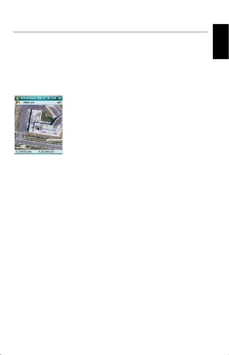
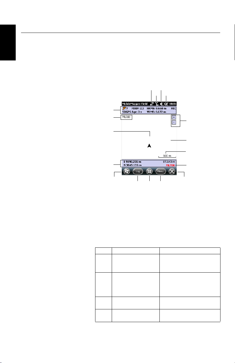
Tap on MobileMapper Field on the Home screen. The main
MobileMapper Field window is described below.
[12]
[14]
[11]
[13]
[1]
[2]
[3]
[4]
[15]
[5] [7]
[6]
[10]
[9]
[8]
[17]
[16]
• [1]: From left to right, by column (these information lines
will not appear until the receiver can determine its own
position):
– Column #1:
Number of satellites currently used in position
computation.
Status of position computation; see table below.
Status Operating Mode Receivers
Conventional Differential
DGPS
GPS using corrections
from a beacon or a base.
SDGPS SBAS Differential
FLOAT RTK, subfoot accuracy
FIXED RTK, centimeter accuracy
MobileMapper 100/120, ProMark
100/120, ProMark 200/ 220
All: MobileMapper 6, MobileMapper 10, MobileMapper 100/120,
ProMark 100/ 120, ProMark 200/
220
MobileMapper 100/120, ProMark
100/120, ProMark 200/220
MobileMapper 100/120, ProMark
100/120, ProMark 200/220
4
Page 13

With the Enable voice guidance option enabled (see
Menu, Options, Voic e tab), a vocal message will be
issued when a position solution is available, and then
every time the position status changes.
– Column #2:
Current value of PDOP.
Age of corrections in all differential modes.
– Column #3: Current values of HRMS and VRMS.
– Column #4: “REC” if the raw data logging option is
unlocked and active.
• [2]: Name of the currently open job.
• [3]: This symbol shows your current position. The arrow
points in your last walking direction.
• [4]: Current 3D position of the receiver (no coordinates
displayed if the receiver has not determined its position
yet).
• [5]: Log button. Use this button to log features. The
button is grayed until GPS positions are computed and a
layer is added to the open job. You can use either the onscreen Log button or the left-hand “–” context-sensitive
key on the keyboard to access the Log function.
• [6]: Button used to show or hide the Microsoft keyboard.
• [7] Menu button. Gives access to the MobileMapper Field
function menu. You can use either the on-screen Menu
button or the right-hand “–” context-sensitive key on the
keyboard to show or hide the function menu.
Menu Option Function
Pause Use this option to pause the current feature logging.
Stop Use this option to stop the current feature logging.
Layers... Use this option to add, modify or remove layers.
Find...
Go To...
Initialize...
Zoom In Increases the scale of the map view by one step.
Zoom Out Decreases the scale of the map view by one step.
Job
Options
Use this option to find a feature previously logged in the
open job.
Use this option to let the receiver guide you to the
selected target (a feature name or any coordinates).
Gives access to two RTK initialization functions (On the
Fly, From Known Point). Usable only when the receiver
can operate in RTK.
Gives access to job-related functions: New, Open (and
Properties if a job is already open).
Allows you to access the following settings: Units,
Antenna, Recording, Map, View, E-compass, Filter, External Devices, Voice and Keyboard.
English
5
Page 14

English
Menu Option Function
Gives access to three tabs describing the current GPS
Status
About Displays the installed version of MobileMapper Field.
Exit Quits MobileMapper Field.
• [8]: Current zoom setting. The current value of scale is
provided, based on the currently selected unit.
• [9]: Area showing a map of the working site (map screen).
Tapping anywhere within this area will return the
horizontal coordinates of the tapped point (expressed in
the coordinate system used in the job). Tap ok to close the
window providing these coordinates.
• [10]: Zoom in/out buttons
• [11]: Battery status
• [12]: Volume setting
• [13]: Phone status
• [14]: Connectivity status.
• [15]: Microsoft Windows button; Used to switch between
the Microsoft Start screen and the MobileMapper Field
application when MobileMapper Field is running.
• [16]: Takes you to the Microsoft Home screen by
minimizing the MobileMapper field window. Tap on the
MobileMapper Field icon ( ) at the bottom of the screen
to return to MobileMapper Field.
• [17]: The “FILTER” warning appears in red characters
whenever the current PDOP is greater than the max.
permitted value. The max. PDOP value can be set in
Menu>Options, Filter tab. When “FILTER” is displayed, no
data collection is possible (Log button greyed). An
abnormally high PDOP is usually due to a too low number
of satellites used.
reception status, in digital (Position) or graphical (Satellites, Signal) form. (In fact the GNSS Status function from
the GNSS Toolbox.)
Dragging the Map
on the Screen
6
Use one of the following two methods.
• For receivers having an ESC key, press this key to move the
arrow symbol representing your current position back to
the center of the map screen. Following this action, the
whole screen is updated to reflect the map shift.
• Drag the stylus in the desired direction.
Because some receivers have no ESC key (e.g. MobileMapper
10), a routine is implemented bringing your current position
Page 15
back to the center of the screen after 15 seconds of idle time
on the map screen.
Setting General
Parameters
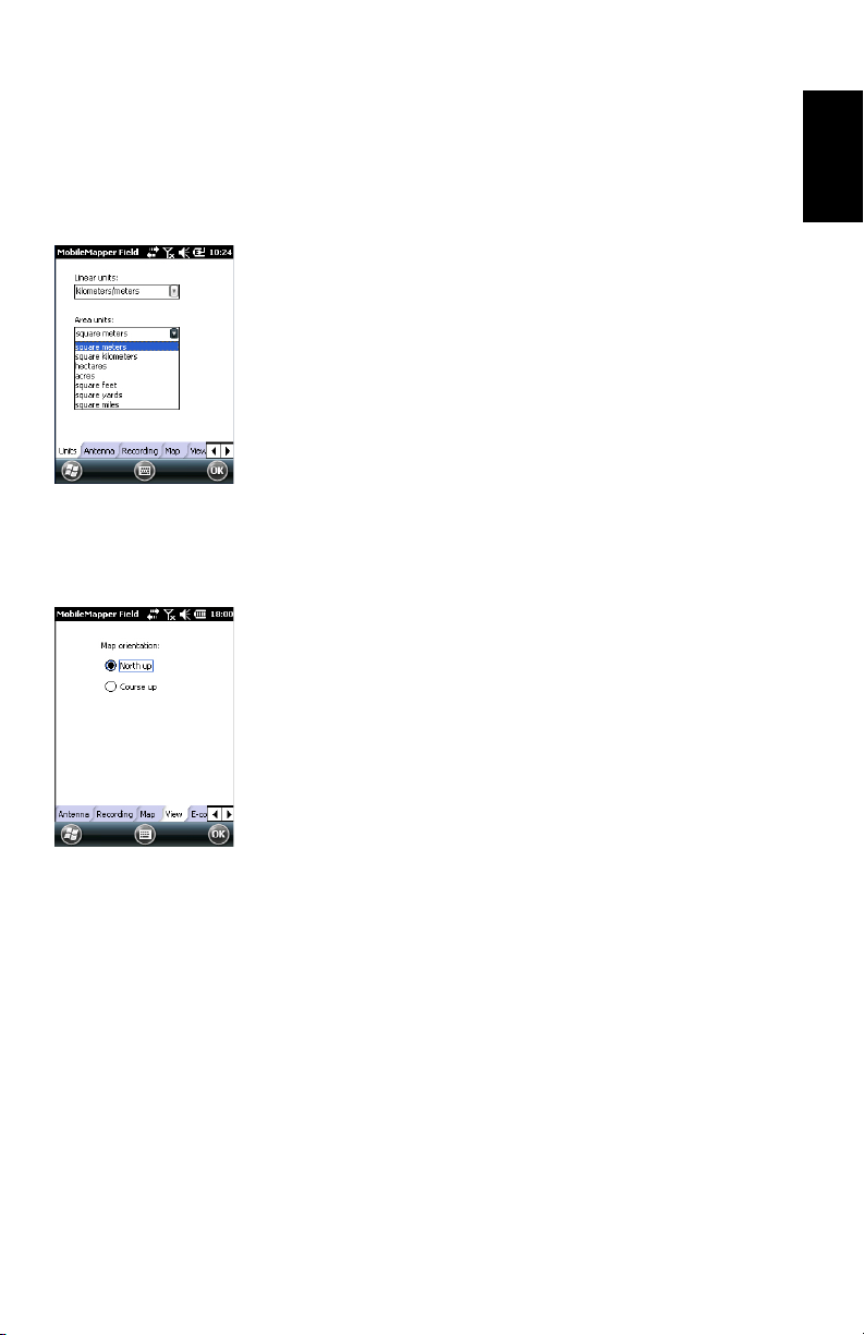
1. Tap Menu>Options.... A new screen is displayed on which
you can choose the measurements units:
• Linear units: Choose between kilometers/meters, miles/
feet or miles/US feet.
• Area units: Choose between square meters, square
kilometers, hectares, acres, square feet, square yards
or square miles.
2. Tap on the Antenna tab and then enter the vertical distance
you will maintain between the top of the receiver (where
the GPS antenna is) and the ground while executing the
job.
This value has to do with your own size since you will be
holding the receiver in your hand throughout the job.
Enter the distance value according to the selected linear
unit. This setting makes sense only for 3D jobs. It can be
ignored for 2D jobs.
3. Tap on the View tab located at the bottom of the screen. A
new screen is displayed allowing you to orientate the map:
• North Up: Map orientation is fixed. The top of the map
screen will always give the North direction.
• Course Up: Map orientation will change as you walk.
The map will rotate in order to have your course always
orientated upward on the map screen. This option
cannot be used if a georeferenced background map is
displayed.
English
4. Tap on the Filter tab and then enter the maximum
permitted PDOP value. No features can be collected when
the PDOP exceeds this value (default: 100). A good
geometry of satellites usually gives PDOP values less than
5.
5. At the bottom of the screen, scroll the list of tabs to the
right until you can see the Keyboard tab. Use this tab to
enable or disable the large on-screen keyboard. The large
keyboard is only available for use within the
MobileMapper Field application. Only the Microsoft
smaller keyboard can be used when working from within
the operating system.
6. For background maps (Map tab), see Adding Background
Maps on page 20.
7. Tap OK to validate all your choices.
7
Page 16

English
Minimizing the
MobileMapper
Field Window
Tap in the upper-right corner of the map screen.
To re-open the MobileMapper Field window, either tap on
“MobileMapper Field” on the Home screen or the icon at the
bottom of the Home screen.
Minimizing the MobileMapper Field window has no effect
whatsoever on software operation. The receiver will safely
continue to collect raw data or features while the window is
minimized.
Quitting
MobileMapper
Field
Use the Menu>Exit option to quit the program.
Caution! Tapping in the upper-right corner of the screen only
minimizes the MobileMapper Field window and so does not
fully exit the program.
8
Page 17
Creating a New Job
During your First
MobileMapper
Field Session
After entering the activation code, MobileMapper Field
displays the map screen.
Because it is the very first time you are using the software,
there is no job open In MobileMapper Field. Follow the
instructions below to create one:
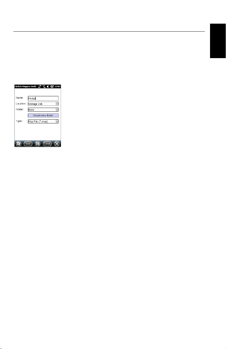
1. Tap Menu>Job>New...
2. Enter the following parameters:
• Name: Enter a name for your job using the Microsoft
virtual keyboard, or the large MobileMapper Field
keyboard,if enabled.
• Location: Choose the storage medium where to store
the job file. You can choose between “Main memory”
or “Storage Card” (if there is an SD or micro-SD card
inserted in the receiver). With MobileMapper 100 or
120, a third option is available (physically located in
the resident memory and named “Storage Disk”).
• Folder: Choose a folder where to store the job file you
are creating.
The None option stands for either the “My Documents”
folder in the main memory, the root folder of the
storage card or, for MobileMapper 100 or 120, the
“Storage Disk” folder in the main memory. Any other
option available from the drop-down menu can only be
a sub-folder of the “My Documents” folder in the main
memory, the root folder of the storage card or, for
MobileMapper 100 or 120, the “Storage Disk” folder
in the main memory.
If you want to use a subfolder where to store your job
files, tap Create New Folder. You can only create
subfolders in the “My Documents” folder, on the
storage card, or in the “Storage Disk” folder.
NOTE: “Storage Disk” has a higher storage capacity
than “MyDocuments” (located in the Main Memory).
• Typ e: For the job file format, choose between “Map
files (*.map)”, the native MobileMapper Field format
and “DXF File (*.dxf)”, which is a standard format for
vector files.
A *.map job is just an “envelope” text file containing
the definition of the coordinate system used as well as
the filenames of all the layers that are part of the job
(layers are held in separate files; see below).
English
9
Page 18

English
The features you will log through that job will be saved
to the corresponding layer files. Each layer consists of
the following five files: <layer_name>.prj,
<layer_name>.shp, <layer_name>.shx,
<layer_name>.dbf, <layer_name>.drw,
In contrast, a DXF job consists of the following files:
One dxf file: The job file in itself. Each newly logged
entity will be saved to that file, whatever the layer from
which it proceeds.
One <job_name>.prj file: Contains the description of
the coordinate system used in the job
One <job_name>.dfs file: Lists the names of the layers
attached to the job as well as the attributes defined in
these layers.
<job_name>_<layer_name>.drw files (one or more):
Each of these drw files contains the full definition of a
layer (visual representation and attributes).
Both Map and Dxf jobs may also use *.mnd and *.mnu
files. These are auxiliary files containing mandatory
attributes (*.mnd) and menu strings for menu-type
attributes (*.mnu).
3. Tap Save to create the job file. What you then get on the
screen depends on the format (map or dxf) you chose for
the job. See Creating New Layers on page 13 for more
details.
It’s only after you are finished with the layers to be
incorporated in your job and you have defined a coordinate
system for the job that you will see the name of the job in
the upper-left corner of the map screen,
Subsequent Uses
of MobileMapper
Field
Opening an
Existing Job
10
The next time you launch MobileMapper Field, the program
will open the job you last opened in the previous session.
If this job is no longer present in the receiver, then a message
will warn you that the program has been unable to open the
job. You will then have to create a new job (see also Using
Templates To Create New Jobs on page 11) or open an
existing one.
• Tap Menu>Job>Open.... By default, MobileMapper Field
browses all the folders in search of all the *.map jobs
stored in the receiver. A new window then opens listing all
these jobs.
Page 19

To list all the DXF jobs stored in the receiver, select the
DXF extension from the Typ e combo box.
Note that MobileMapper Field can also support ESRI’s
AXF database format for GIS data. After you have
downloaded one of these files to your receiver, you can
open it with MobileMapper Field and add or modify
entities the same way as you would in an open MAP or DXF
job. You cannot however create a new AXF file with
MobileMapper Field. You cannot either add or remove
layers to/from an AXF job.
To list all the AXF jobs stored in the receiver, select the
AXF extension from the Typ e combo box.
• After you have found the job you wish to open, tap on its
name in the list. This opens the job and takes you to the
map screen where you can see the features already logged
in the different layers.
English
Viewing the
Properties of the
Open Job
Using Templates
To Create New
Jobs
• Tap Menu>Job>Properties. MobileMapper Field then
displays a two-tab window. The first tab provides the job’s
name, type and location (folder). The second one views
the properties (projection and datum) of the coordinate
system used in the job.
• Tap OK (or press ESC on MobileMapper 100/120 or
MobileMapper 6) to return to the map screen.
When creating a new job in a given format (MAP or DXF) while
a job of the same format is currently open, once you have
named that new job and specified in which folder to save it,
MobileMapper will prompt you to use the open job as a
template for the new job. What does that imply if you choose
“Yes”?
•For a MAP job:
MobileMapper Field will create a “<new_job_name>”
folder in the specified folder to which all the layers found
in the template job will be copied.
The copied layers will be emptied (i.e. all features
deleted) so that you can start collecting new features from
scratch using these layers, which are now fully part of the
new job.
Remember that each of the copied layer will keep exactly
the same name, and same attributes, as the one from
which it is derived. (see also diagram below):
11
Page 20

English
Specified folder
(In main memory,
”None” = My Documents)
<New_job_name>.map
<New_job_name>
“Emptied” Layers, i.e.
file names unchanged,
all definitions of attributes
preserved, but all features
removed
• For a DXF job: MobileMapper Field will duplicate all the
files relevant to the job to the specified folder and will
empty the created DXF file (no more entity found in this
job). If the new DXF job is created in the same folder, then
only a new empty DXF file will be created since in this
case all the other files can be shared smoothly by the
original and duplicate jobs.
If you don’t want to use the open job as a template, choose
“No”. You will then have to define manually the coordinate
system used as well as each of the layers that are expected to
be part of the job (new or already existing ones for map jobs,
new ones necessarily for dxf jobs).
12
Page 21
Creating New Layers
Introduction Creating a layer consists of defining a specific profile for
Attaching Layers to
a Map Job
features you would like to log in the field. The layer creation
English
process will be different depending on whether you chose
“MAP” or “DXF” for the job format:
• MAP format: Each layer is held in an individual file. The
layer format can be either “SHP”, “MIF” or “CSV”.
– An SHP layer can only contain a single type of feature.
When creating a new layer, you should first indicate if
it is created to hold 2D/3D point, 2D/3D line or 2D/3D
polygon features.
– A MIF layer can contain any type of feature (point, line
or polygon).
– A CSV layer can only support point features.
• DXF format: Each layer consists of a drw file created in the
same folder as the DXF job file. A layer attached to a DXF
job can contain any type of feature (point, line or polygon).
Here are the two different contexts in which you can create a
new layer to be attached to a Map job:
• With a job open in the current MobileMapper Field
session, you tap Menu>Job>New... to create a new *.map
job for which the program will ask you directly to add new
layers, either by creating new ones or by selecting existing
ones.
• With a job open in the current MobileMapper Field
session, you tap Menu>Layers... and then you tap on the
Add button.
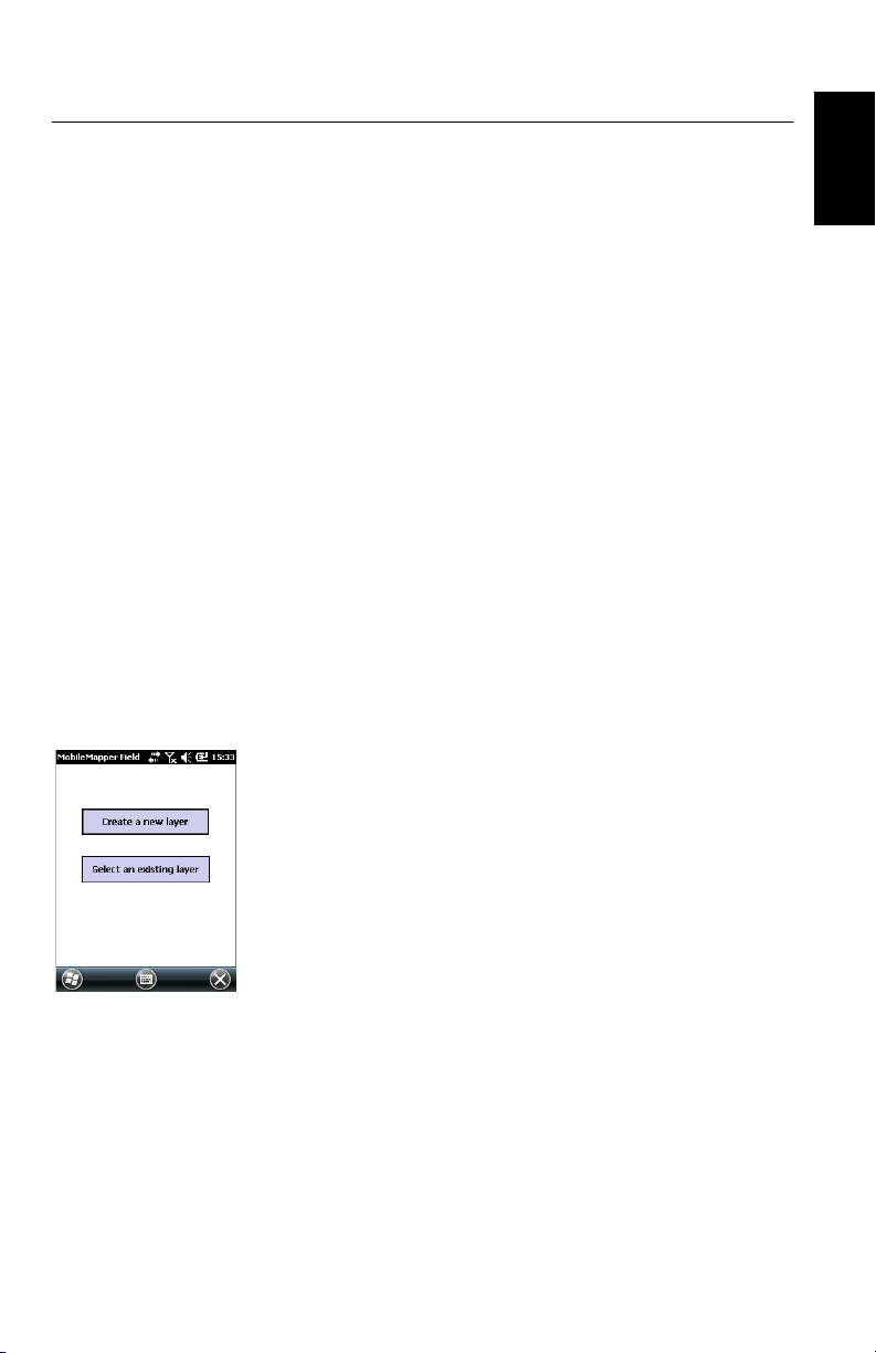
From the screen displaying the Create a new layer button, do
the following:
1. Tap the Create a new layer button.
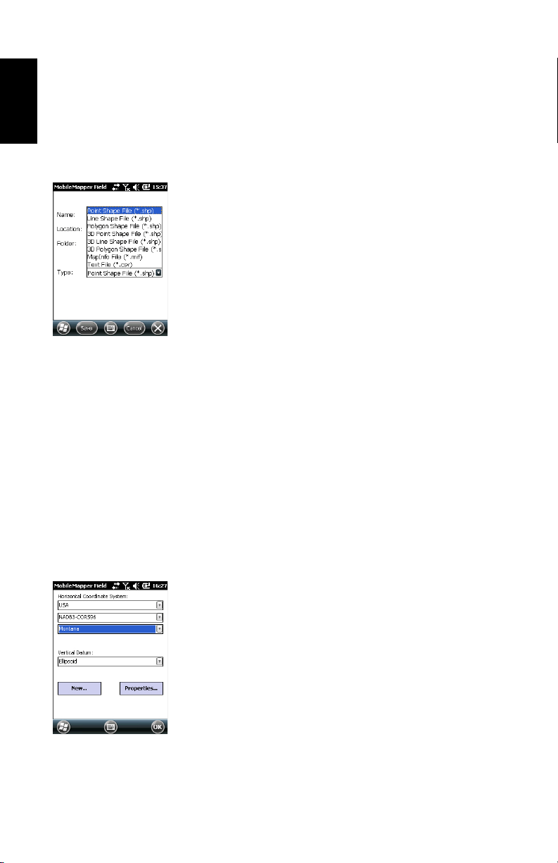
2. Enter the following parameters:
• Name: Enter a name for the layer using the virtual
keyboard (10 characters max.). The name of the layer
should depict the type of features you will collect with
this layer (e.g. Points, Lines, Areas, etc.).
13
Page 22
English
• Location: Choose the storage medium where you want
to store the layer. You can choose either “Main
memory” or “Storage Card” (if there is an SD, or microSD card inserted in the receiver). With MobileMapper
100 or 120, a third option is available (physically
located in the resident memory and named “Storage
Disk”).
• Folder: Choose a folder where you want to store the
layer you are creating. This choice should be made in
conjunction with the choice of the storage medium
(see Location).
The None option stands for either the “My Documents”
folder or the “Storage Disk” folder in the main memory,
or the root folder on the storage card. All other options
available in the drop-down menu will be subfolders of
the “My Documents” folder or the “Storage Disk”
folder in the main memory, or the root folder on the
storage card.
It is a good idea to store your layers in the same storage
medium and folder as the open job so that all the files
created for the job be found at the same location.
If you want to use a specific folder where to store your
layers, first create it using File Explorer. You can only
create new folders in the “My Documents” folder, in
the “Storage Disk” folder or on the storage card.
• Typ e: Choose the type and/or format of the layer you
want to create:
SHP layer: Depending on your choice the layer will
hold 2D/3D points, 2D/3D lines, or 2D/3D polygons.
MIF layer (can hold any type of feature).
CSV layer (point feature type only).
3. Tap the Save button to proceed. If you are defining the
second or next layers, go directly to step 5. If you are
defining the first layer in the open job, the program will
first ask you to define a coordinate system for the job:
• First field: Choose the country you are working in. You
may also choose a worldwide system such as UTM or
Worldwide Geodetic System.
• Second field: The number of options available in this
field depends on the selected country. Select the
datum that is suitable for your job.
See also Coordinate Systems on page 38.
• Third field: The number of options available in this
field depends on the selected country. Choose a
14
Page 23

projection that is suitable for your job. Select Latitude/
Longitude for no projection.
• Fourth field: Choose a vertical datum in which to
express the Z coordinate.
“Ellipsoid” (no geoid used) and “EGM84” (global
earth geoid model) are the two default options. Other
geoids may be prompted in this field after you have
downloaded them to the receiver from the Internet via
the link found on the MobileMapper Software CD.
4. Tap OK.
5. The program now asks you to define the properties of the
layer. The table below summarizes the different properties
you should define for the layer, according to its type.
Properties
Symbol • • •
Color • • •
Style • •
Fill • •
Attributes • • • • •
Label • • • • •
Scale • • • • •
2D or 3D
Point
2D or 3D
Line
2D or 3D
Polygon
Mif
layer
Csv layer
For more information on layer properties and how to define
attributes, see Layer Properties on page 16.
6. Tap OK when you are finished with the properties of the
layer. A message then asks you whether you want to add a
new layer.
Warning! After you have tapped OK, the definition of a
layer can still be modified using the Modify button.
However its list of attributes is then frozen: None of the
existing attributes can be deleted or modified and you are
not allowed to add a new one. If you need to change the
attributes in a layer, the only possible solution is delete
the layer and re-create it from scratch.
7. Add as many layers as necessary, using the above
procedure.
English
Adding Layers into
a DXF Job
The procedure is quite similar to attaching a layer to a Map
job. Among the similarities are first the prior necessity to
define a coordinate system for the job and second, the
availability of the same viewing options and attributes for the
features you will log through a given layer (see Adding
Existing Layers to a Map Job on page 19 for the details).
15
Page 24

English
But unlike Map jobs, DXF jobs cannot use or re-use layers
that are external to the job. With DXF jobs, you can only
create one or more new layers within the job, right after
defining the coordinate system. Another difference lies in the
absence of an assumed feature geometry in a layer, which
means all types of features, whether points, lines or polygons,
can be logged in the layer.
Layer Properties Symbol
57 different symbols are available to represent a point feature
on the map screen.
Color
15 different colors are available to represent a line feature or
the contour of a polygon feature on the map screen.
Style
The line style (thin, medium, thick or dash) is used to
represent a line feature on the map screen.
Fill
Eight different patterns are used on the map screen to fill the
area covered by a polygon feature.
Attributes
Attributes are an important part of a layer since they are
designed to hold specific information (other than position)
that you want to collect for each feature.
The number of attributes you can create in a layer is limited
to 50.
Each attribute is defined by a name (10 characters max.) and
a type.
You may decide to make an attribute a “mandatory”
parameter to describe any feature you will log in the layer.
This means the operator won’t be able to complete the
logging of a feature until the mandatory attribute has properly
been defined. Any type of attribute may be made mandatory.
There are eight different attribute types of attributes, as
summarized below.
Attribute
Typ e
Text Entering comment, etc.
Menu
Purpose
Choosing an option (menu item) that
suits the attribute for the visited feature.
Additional Information
Needed
Maximum number of
characters.
All possible menu items
for this attribute.
16
Page 25

Attribute
Typ e
Image
Voice Recording voice comment -
Numeric Entering a number.
Date
Time
Yes /N o
Attaching a picture taken with the builtin camera to the visited feature.
Entering the current logging date (mm/
dd/yy).
Entering the current logging time
(hh:mm:ss)
Choosing “Yes” or “No” in response to
the statement suggested by the attribute name for the visited feature.
Purpose
Additional Information
Needed
-
Max. number of digits and
decimal places.
-
-
NOTE: For best quality voice recording, see Handheld
Platform for MobileMapper 120, ProMark 120 & ProMark
220 Getting Started Guide, Voice Setting. No particular
setting is required for MobileMapper 10 (voice recording
quality is good by default).
Some useful attributes with preset names are displayed for
each layer type (see table below). It’s up to you whether or not
to create them.
English
Attribute
Name
Picture Image • • • •
Sound Voice • • • •
Satellites Text • •
PDOP Text • •
Status Text • •
HRMS* Text • •
VRMS** Text • •
Length Numeric • •
Perimeter Numeric • •
Area Numeric • •
*: HRMS stands for the estimated horizontal error
**: VRMS stands for the estimated vertical error
Attribute
Typ e
Point
Layer
Line
Layer
Polygon
Layer
MapInfo
layer
As opposed to the attributes you have to enter manually
(“user-set” attributes), these useful attributes with preset
names are automatically added by MobileMapper Field
(software-set attributes) after the feature has been logged.
For example, using “Satellites”, “PDOP”, “Status”, “HRMS”
and/or “VRMS” allows the program to automatically assign
the current value of each of these attributes to a point you are
17
Page 26

English
logging. “Status” refers to the position computation mode
used at that time.
Also, using “Length” allows the program to automatically
assign the length of a line as one of its attributes. The length
of the line is computed as you walk along the line. The result
of the computation only appears after you have stopped
logging the line, when you review all its attributes. The same
is true with the “Perimeter” and “Area” attributes for a
polygon.
Adding attributes to a layer:
• From the Attributes tab of the layer properties window, tap
the Add... button.
• Enter a name for the attribute using the virtual keyboard.
• Select a type for this attribute.
• If this attribute will be a mandatory one to describe the
logged features, enable “Mandatory”.
• If applicable, set the additional one or two parameters.
• Tap on the Add button. This takes you back to the
Attributes tab where is now listed the attribute you have
just created.
• Resume the previous six steps until all the attributes have
been created.
Label
This setting is used to select the label you want to see on the
map screen, next to the features collected through that layer.
The label can only be one of the attribute values pertaining to
the feature. Choosing “None” means there won’t be any label
displayed.
Showing/Hiding
Features on the
Map Screen
18
Scale
This setting is used to display or hide the layer on the map
screen, depending on the current scale value used. The scale
property of the layer operates as a threshold, which will order
the layer to be hidden if the scale value on the map screen is
less than this threshold.
• Tap Menu>Layers...
• Enable or clear the check box placed before each layer
name to respectively show or hide the layer on the map
screen. Showing a layer means showing all the features
logged in that layer.
Page 27
Adding Existing Layers to a Map Job
• Open the job in which to add layers, using
Menu>Job>Open....
• Tap Menu>Layers. A new window opens listing all the
layers currently attached to the map.
• Tap on the Add... button
• Tap on the Select an existing layer button
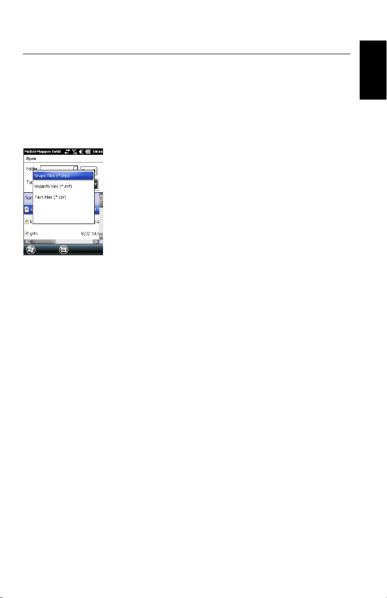
• Tap in the Type field and select “*.shp”, “*.csv” or
“*.mif”. MobileMapper Field browses all the folders in
search of all the layers of that type stored in the receiver.
• Select the file you want to add to the job as a layer. This
opens a new window showing the viewing options,
attributes and scale defined for this file.
• Tap OK. This takes you back to the screen showing all the
layers attached to the job, including the new layer you’ve
just selected.
• Tap OK to return to the map screen. The new layer is now
available for feature logging.
NOTE 1: Adding an existing layer to a new job as the first
layer in this job will cause the layer’s coordinate system to
definitively become the coordinate system attached to the
new job.
NOTE 2: Attempting to add a layer that is incompatible
with the coordinate system used by the job will cause a
warning message to be displayed. You can however
override the message and ask MobileMapper Field to add
this layer. In this case, be aware that the layer will contain
positional information based on different coordinate
systems. It will be your responsibility to identify which
coordinate system is used in the description of each
feature.
NOTE 3: “Type_M” SHP files created with third-party
equipment or software may be added to a map job as a
layer. You will be able to collect data using this layer but
you won’t be able to access the “M” field specific to that
type of layer.
English
19
Page 28

Adding Background Maps
English
Background maps can be displayed on the map screen to
help you better locate the different features found in the
working area. Two types of background maps are supported:
• Background maps in vector format (OSM files)
• Background maps in raster format (ecw, bmp, gif, tif, jpg
or jp2 files)
In order to be used in MobileMapper Field, a background map
must be properly georeferenced.
OSM files are “naturally” georeferenced due to their very
nature. (To create an OSM file go to http://
www.openstreetmap.org/, follow the instructions to extract
the portion of map you need for your job, and then download
it to your receiver.)
With a raster map, georeferencing may have been done earlier
using a third-party tool or it can be done, using one of the two
procedures below, after defining it as a background map in
MobileMapper Field:
1. You know the coordinates of the reference points used to
georeference the image. You will have to tap successively
on each of these points on the map. For each point, you
will have to enter its coordinates.
2. You go to the field and stand successively on each
reference point used to georeference the image. (You
should choose reference points that can easily be spotted
both on the map and in the field.) You will have to tap
successively on each of these points on the map. Each
time, the receiver will automatically fill in the
corresponding fields on the screen with the computed
coordinates of your current location.
MobileMapper Field may accept several background maps,
each holding a different geographical area. All logged
features will always appear over the background map.
• Tap Menu>Options and then on the Map tab.
• Tap on the Add... button
20
Page 29

• Tap in the Type field and select the format of the file
containing the background map:
– ECW Enhanced Compression Wavelet (ecw)
– Bitmap (bmp)
– GIF (gif)
– GeoTIFF (tif)
–JPEG (jpg)
– JPEG2000 (jp2)
– Open StreetMap (osm)
MobileMapper Field then browses all the folders in search
of all the image files stored in the receiver meeting the
current Typ e selection.
• Tap on the name of the image file you want to add. This
automatically adds the file to the list of background maps.
A message will warn you if you are attempting to add an
already georeferenced background map that uses a
coordinate system different from the one used in the open
job. If the image file needs georeferencing, MobileMapper
Field will first invite you to make this georeferencing (see
the procedure explained below).
In contrast, adding a background map in OSM format will
never raise a warning message because, although
originally in WGS84, the OSM file will be transformed to
be always matching the coordinate system of the open job.
Like layers, each of the added background maps can be
shown or hidden on the map screen. Set accordingly each
of the check boxes placed before the names of the
background maps (cleared= hidden, ticked= shown).
• Tap OK to return to the map screen. Note that the map
screen will show the background map(s) only after the
receiver can compute a position. Remember you may also
have to press the ESC button (MobileMapper 100 or 120)
so that the map screen can show the location of the first
logged feature.
English
21
Page 30

Georeferencing an
English
Image File
Georeferencing an image file means defining at least three
reference points giving the position of the image in space.
Defining a reference point means entering its precise X-Y-Z or
Lat-Lon-Height coordinates depending on the coordinate
system used in the currently open job.
The larger the number of reference points you define, the
more evenly distributed these points over the entire image,
the better the georeferencing of the image.
To georeference an image, do the following after adding it to
the list of available background maps:
• Select the name of the background map from the list.
• Tap on the Modify button.
• Find the point on the image for which coordinates are
known. Adjust the zoom setting and drag the stylus on the
image if necessary.
• Tap on the point location and then enter its ID and
coordinates. If you are currently standing at that location
and the receiver delivers a valid GPS position, you don’t
need to enter any coordinates. The receiver will do that for
you.
• Tap Add to enter and complete the definition of this point.
• Resume the previous three steps until all the reference
points have been defined. Each point on the map is
represented by a red circle. If this happens, you can
always delete a bad point by double-tapping on it and then
tapping on the Delete button.
• Tap OK to complete the georeferencing process. This takes
you back to the screen showing the list of background
maps.
More about
Background Maps
22
• The background map will be displayed only when it is
geographically close to the computed GPS position and
the zoom is set properly.
• For large background maps, you may have to zoom in
several times before the map screen can start viewing
details of the background map.
• If a background map is not properly georeferenced, the
background map will never appear on the map screen, and
the reference points you incorrectly created on the
background map will all be deleted. Try again, this time
with correct point location and coordinates.
Page 31

• It is highly recommended to place the original image file
used to create the background map in the same folder as
the job file using it. Observing this rule will simplify the
download procedure.
• When georeferencing an image, the original image file is
unchanged and three new files are created:
Created files Designation
<image filename>.prj Coordinate system used
Auxiliary data. “xx” in the extension stands for
<image filename>.xxw
<image filename>.<image
file extension>.ref.txt
the first two letters in the extension of the original image file (e.g. “JP” for a jpg file)
Coordinates of reference points and coordinate
system used.
When the original image file is in TIF format, some of
these three files may not be created.
English
23
Page 32

Logging New Features
Automatic Manual
i
i
i
i
Continuous lines show actual paths traveled. Dotted lines show features, as logged.
English
Introduction For each new feature you log in the field, MobileMapper Field
allows you to set the following parameters, just before it
actually starts logging the feature:
•On the Layer tab, you can choose:
– The name of the layer corresponding to the feature you
want to log (from the list of layers found in the job).
– For MIF layers, and for those contained in a DXF job,
the geometry (i.e. point, line or polygon) of the feature.
This field is preset for CSV layers (points exclusively)
and for SHP layers.
•On the Settings tab, you can set:
– The position averaging time at the end of which the
coordinates of a point feature will be logged. The
longer the averaging time, the better the precision you
get for each of your points. This implies staying still on
the point throughout the averaging time.
– The automatic or manual vertex logging mode for a line
or polygon feature:
In Automatic mode, the receiver automatically picks up
the position of each of the points ( ) as you keep
walking along the feature. The logging rate i is preset
and represents either the time elapsed or the distance
traveled.
In Manual mode, you stop at each of the vertices ( ),
on which the receiver computes a position averaged
over n seconds
24
Page 33

•On the Offset tab, you can set:
Right
Bearing
Left
d= Horizontal Distance
d
d
d
N
1. Log
2. Pause
5. Resume
3. Log
4. Stop
6. Stop
– The bearing, horizontal distance and vertical offset if
you wish to offset a point feature.
– The direction (left or right), horizontal distance and
vertical offset if you wish to offset a line or polygon
feature.
MobileMapper Field also allows the logging of two features to
be run concurrently (“double logging”). This can be done
through the appropriate use of the Pause/Resume/Stop
functions. Double logging is useful to reduce both the time
spent logging features and the distance walked in the field.
English
Prerequisites
MobileMapper Field allows you to delete a logged feature
directly from the map screen showing the location of this
feature.
• The receiver is on and MobileMapper Field running.
• A Map job is used, which contains three SHP layers: a
point layer named “Points”, a line layer named “Lines”
and a polygon layer named “Areas”. All layers are set to
be seen on the map screen.
• The units used have been set to meet your requirements.
• The reception status is good (number of satellites>6,
PDOP<3). Especially for MobileMapper 6 and
MobileMapper 10, optimum position accuracy is achieved
in real time after waiting about five minutes of good
25
Page 34

English
reception status. Then you can start collecting your first
feature.
Logging a Point
Feature
N
Bearing
d
d= Horizontal Distance
VO
HA
Ground
Coord Sys
HF = HG - HA + VO
Where:
HF: Feature height expressed
on coordinate system used (computed)
HG: GNSS height (measured)
HA: Antenna Height above ground
(user set)
VO: Feature height above ground
(vertical offset, user-set)
HG
• Stand near the point you want to log.
• Tap Log (or press the “–” key underneath). A menu
appears listing all the layers in the job.
• Tap on the point layer name (“Points” in our example).
• Tap on the Settings tab and check or change the averaging
time expressed in seconds. As the last chosen averaging
time is prompted by default, you may not have to view this
tab every time you log a new point feature.
• To log the point with an offset, tap on the Offset tab and
enter the following parameters (for no offset, just check
that the horizontal distance and vertical offset are 0 on
this tab and proceed to the next step):
– Bearing: This field is filled automatically either from
the GPS compass, the E-compass if this option is
activated in Menu> Options> E-compass, at the time you
access the Offset tab, or from the range finder, if there
is one (see below).
If the E-compass is used, a valid measurement will be
made if you take care to hold the receiver horizontally
in the direction of the point feature, before you start
logging the feature.
If neither the E-compass nor a range finder is used,
then the GPS compass can provide this value by
default. A valid measurement will be made if you take
care to steadily walk in the direction of the point
HF
feature before you start logging the feature.
– Horizontal Distance field: Distance to the point feature.
If a range finder is used, tap on the Read Range Finder
button once the range finder can provide valid
measurements. This action will automatically fill in the
Bearing and Horizontal Distance fields.
If no range finder is used, type an estimate of the
horizontal distance directly in the field using the
keyboard. The better you estimate the distance, the
better the collected position.
– Vertical offset field: Height deviation from the physical
location of the feature to the ground, positive if above
the ground, negative otherwise (see illustration).
26
Page 35

• Tap OK. MobileMapper Field instantly starts averaging the
point position, as indicated in the progress bar at the
bottom of the screen. The screen also provides a detailed
report of the current GPS status as the point position is
being averaged (coordinates of computed position,
number of satellites used, PDOP value, computation
mode, age of corrections if applicable, HRMS and VRMS).
Don’t forget to hold the receiver still throughout the
averaging time.
There are basically two methods for completing the point
logging sequence at this stage:
1. Either you wait until the averaging time is up and then
you enter the value of each attribute (1st method). See
also Entering Values for Attributes on page 30)
2. Or you start entering the values of the attributes as
soon as MobileMapper Field starts averaging the point
position (2nd method). This is the fastest method,
especially if the averaging time is 10 seconds or more
and/or there is a large number of user-set attributes for
the point).To use this method, just tap the Attributes
button in the lower bar, and then enter the value of
each attribute.
When you are finished with entering the attribute
values, depending on the requested averaging time
and how long it took you to set the attribute values,
MobileMapper Field will either return to the Averaging...
screen (You were faster than the preset averaging time
entering values of attributes) or it will directly switch
to the attributes list (You were slower than the preset
averaging time entering values of attributes).
NOTE: While the point position is being averaged. you
are also allowed to shorten the averaging time if needed
by tapping on the Stop button located in the lower bar. You
will then need to confirm this request by tapping Yes.
English
27
Page 36

English
• When the averaging time is up (and you have entered all
the attribute values if you have used the 2nd method),
MobileMapper Field shows the complete list of attributes
assigned to the point, the user-set attributes first, then the
software-set attributes, if any. The averaged position of
the point always appears at the bottom of the list (this
position may be regarded an an unconditional, softwareset attribute). If you have used the first method, you
should now enter the value of each “manual” attribute
(see Entering Values for Attributes on page 30).
NOTE: The “Autonomous” position computation mode
will be reported as “RAW” in the list of properties.
• Tap OK to return to the map screen, which now shows the
location of the point according to the representation
defined in the layer properties.
NOTE: If some attributes are mandatory and you haven’t
set them yet when you tap OK, MobileMapper Field will
first ask you to set them in their order of appearance in the
list of attributes before returning to the map screen.
Logging a Line or
Polygon Feature
• Stand at the beginning of the line or polygon you want to
log.
• Tap Log (or press the “–” key underneath). A menu
appears listing all the layers in the job.
• Tap on the desired layer name (“Lines” or “Areas” in our
example).
• Tap on the Settings tab and check or change the vertex
logging mode. As the last chosen mode is prompted by
default, you may not have to view this tab every time you
log a new line or polygon feature. Choose one of the
options below:
– Automatic: Selecting this option means the receiver will
automatically log points along the line or polygon at
regular intervals of time or distance. Enter the desired
value for this interval, either in seconds or meters.
– Manual: Selecting the option means you are only
interested in logging the vertices of the line or polygon,
and not points regularly distributed along the feature.
Enter the position averaging time, in seconds, that you
wish to spend on each vertex.
• To log the line or polygon with an offset, tap on the Offset
tab (otherwise skip this step) and enter the following
parameters (for no offset, just check that the horizontal
distance and vertical offset are 0 on this tab and proceed
to the next step):
28
Page 37

Left
d
Right
d
d= Horizontal Distance
VO
HA
Ground
Coord Sys
HF = HG - HA + VO
Where:
HF: Feature height expressed
on coordinate system used (computed)
HG: GNSS height (measured)
HA: Antenna Height above ground
(user set)
VO: Feature height above ground
(vertical offset, user-set)
HG
– Direction: this parameter tells the program whether the
real feature is on your left or right.
– Horizontal Distance field: Horizontal distance
perpendicular to the line or polygon feature.
If a range finder is used to measure this distance, tap
on the Read Range Finder button once the range finder
has got a valid measurement. This will automatically
fill in the field.
If no range finder is used, type an estimate of the
horizontal distance directly in the field using the
keyboard. The better you estimate the distance, the
better the collected positions.
– Vertical offset field: Height deviation from the physical
location of the feature to the ground, positive if above
the ground, negative otherwise (see illustration).
• Tap OK. MobileMapper Field instantly starts logging the
HF
feature.
If you have selected the automatic vertex mode, start
walking along the feature. You will then see a line being
drawn on the screen as you walk.
If you have selected the manual vertex mode, the receiver
will assume you are standing on the first vertex and so it
will log this vertex according to the chosen averaging time.
You will then have to walk to the next vertex and then
select Menu>Resume to log the position of the second
vertex, etc.
• When you arrive at the end of the feature, tap Menu and
select Stop. MobileMapper Field then automatically
switches to the attribute list.
• Define each attribute for the line or polygon (see Entering
Values for Attributes on page 30).
NOTE: Like point features, you can enter the values of
attributes for a line or polygon not only at the end of the
feature logging sequence, but also at any time while
walking along the line or polygon. This can be done by
tapping on the Attributes button located in the lower bar.
• Tap OK to return to the map screen, which now shows the
location and shape of the feature according to the
representation defined in the layer properties.
NOTE: If some attributes are mandatory and you haven’t
set them yet when you tap OK, MobileMapper Field will
first ask you to set them in their order of appearance in the
list of attributes before returning to the map screen.
English
29
Page 38

Entering Values for
English
Attributes
Depending on the type of the attribute, you will have to
perform the following:
• For a text attribute, type your text using the virtual
keyboard and then tap OK.
• For a numeric attribute, type your number using the
virtual keyboard and then tap OK.
• For an image attribute, the following menu is displayed:
– Camera: Runs the camera utility so you can take a
picture. For more information on using the built-in
camera, see HandHeld Platform for MobileMapper
120, ProMark 120 and ProMark 220 Getting Started
Guide, Using the Camera, MobileMapper 10 Platform
Getting Started Guide or MobileMapper 6 Platform
Getting Started Guide.
NOTE: Picture attributes are saved as JPG files in the
same folder as the layer they belong to. The file naming
convention used is Img#.jpg where # is the picture
number (1, 2, 3, etc.). The picture number is ascribed
in chronological order, with no reference to any other
file.
– View: Allows you to view the picture assigned to the
attribute.
– Select: Allows you to display a slide show of all the
pictures taken so you can choose which one to assign
to the attribute.
– Remove: Allows you to disconnect the selected jpg file
from the picture attribute. This does not delete the
picture itself, which is still present in the slide show.
30
• For a voice attribute, the following menu is displayed:
Page 39

– Record: Opens the recorder bar from which you can
6
start, then, stop recording a voice message as an
attribute of the current feature.
24 6
13 5
1: Drags the recorder bar.
2: Starts voice recording.
3: Pauses voice recording.
4: Plays back voice recording.
5: Stops voice recording.
6: Closes the recorder bar
– Play: For check purposes, select this function to play
back the voice message you’ve just recorded
(equivalent to “4” button on recorder bar)
– Remove: Select this function to delete the existing
voice message. You will use this function when you
wish to record a new voice message for the current
feature.
English
NOTE: Voice attributes are saved as WAV files in the same
folder as the layer they belong to. The file naming
convention used is Sound#.wav where # is the record
number (1, 2, 3, etc.). The record number is ascribed in
chronological order, with no reference to any other file.
• For a “Yes/No” attribute, the default choice is “No”. Tap
on the attribute name to change the setting and then tap
OK.
• For a date attribute, the current date is automatically
assigned (software-set attribute). To change the date, tap
on the Date attribute and select the new date from the
displayed calendar and then tap OK.
• All other software-set attributes are assigned
automatically by MobileMapper Field.
31
Page 40

English
Using the Pause/ Resume Function
While logging a line or polygon, you may want to pause data
logging because external events require that you do so or you
want to start the logging of a second feature (double logging
feature) (see Double Logging on page 32). Follow the
instructions below.
• Tap Menu>Pause to pause data logging.
• Later when you are ready to resume data logging, go back
to where you left the line or polygon, tap Menu>Resume to
continue the data logging as you walk along the feature.
Double Logging While logging a line or polygon, you may want to log another
feature found along the way, whether a point, a line or a
polygon. Follow the instructions below.
• Tap Menu>Pause to pause the data logging of the feature
in progress.
• Move to the second feature you want to log.
• Tap Log, select the layer of the second feature, make the
necessary settings and log this feature as you would in the
usual case.
• Tap Menu>Stop when you are finished with the logging of
the second feature.
• Go back to where you left the first feature.
• Tap Menu>Resume to continue with the logging of the first
feature.
• Tap Menu>Stop when you are finished with the logging of
the first feature.
More about
Feature Logging
32
• The number of point features that can be logged in a
session is only limited by the memory capacity of the
storage medium used.
• Up to 10,000 points can be logged in a single line or
polygon.
• When logging a long line or polygon, MobileMapper Field
will automatically save the data to a temporary file every
10 minutes of data logging.
If a power failure occurs while logging a line or polygon,
the feature is automatically saved before the power
failure. Because line and area features are saved
automatically every 10 minutes of actual logging, if a
power failure occurs unexpectedly and you have been
logging a line or polygon feature for the last 15 minutes,
then most probably only the first 10 minutes of the feature
will be saved. If that happens, do the following:
Page 41

– Insert a fresh battery or connect the receiver to an
external power supply.
– Turn the receive back on and launch MobileMapper
Field. This will re-open the last job open.
– Quit MobileMapper Field. Only from this this moment
can the job file be dowloaded to your computer with
the last logged feature (line or polygon) fully restored.
• If MobileMapper Field fails to save a feature because
there is not enough memory left, you can still delete
unnecessary files and try again. Follow the instructions
below when this happens.
– Minimize MobileMapper Field
– Run File Explorer
– Delete unnecessary files
– Return to MobileMapper Field and stop logging the
feature. The feature will normally be saved if enough
memory space has been cleared.
English
Repeating
Attributes
The Repeat Attributes function lets the receiver automatically
duplicate the attributes from your last logged feature to the
next one (mandatory attributes, if any, will also be
duplicated). This will however be possible only if the next
feature you want to log is of the same type as the feature you
have just logged.
Follow the instructions below to use the Repeat Attributes
function:
• Go to a feature, log this feature and enter all its attributes,
as is normally done.
• Go to the next feature. After having tapped Log and made
sure the same type of feature is selected, you will see the
Repeat Attributes option appear at the bottom of the screen.
• Enable this option and tap OK to start collecting the
feature data. When the receiver has finished collecting the
data, the screen will display the position and attributes of
the feature. Note that all the feature attributes are exactly
those of the previous feature, which is precisely what you
wanted to get.
• Just tap OK to complete the collection of the feature and
proceed to the next one.
The Repeat Attributes function will help you work faster when
logging a series of similar features presenting the same
attributes. For example, the function will be useful if you are
33
Page 42

English
collecting a row of trees of the same variety, same age, same
health status, etc.).
Warning! The Repeat function does not apply strictly to Date
& Time attributes. In fact the “repeated” Date & Time
attribute will be set automatically to the current values of
Date & Time and not to the values assigned to the Date &
Time attribute of the previous feature.
Deleting Features
For some reason or other, you may want to delete a feature,
whether a point, a line or a polygon. This is possible from the
map screen showing the location of the feature:
• Through zoom and drag operations, adjust the view of the
map screen in order to see the location of the feature.
• Tap on the feature. This opens a new window showing the
properties of the feature.
• Tap on the Delete button shown in the lower bar. The
feature is deleted from the corresponding layer, after prior
confirmation, and its location removed from the map
screen.
34
Page 43

Revisiting Features
Going Back to a
Feature
• Tap Menu>Go To.... The receiver allows you to go back to a
feature according to one of the following two methods:
1. Enter target coordinates: Choose this option if you want
to go back to a point feature for which you know the
coordinates (latitude/longitude or Easting/Northing (X/
Y) depending on the coordinate system used in the
map file). After you have entered the two coordinates,
tap OK. This takes you back to the map screen.
2. Select destination from list: Choose this option if you
want to go back to a feature stored in the open map.
First of all, you have to select the layer the feature
belongs to. Use the Go to drop-down menu to make this
choice. As a result, the screen lists all the features
contained in that layer. Features are listed from the
nearest to the farthest from your current location.
Select the desired one simply by tapping on its name.
This takes you directly back to the map screen.
Whatever the method used, you can now see, on the map
screen, a yellow/red segment connecting your current
position to the feature.
For a line or polygon, MobileMapper Field will draw a
segment between your current position and the point in
the line or polygon the nearest to you.
In the lower bar, you can read the distance and the bearing
to the feature.
• Walk in the direction indicated on the screen until you
reach the feature.
If the voice guidance is activated (see Menu>Options, Voic e
tab), right/left instructions as well as the distance to the
feature will be issued at regular intervals of time as vocal
messages.
English
35
Page 44
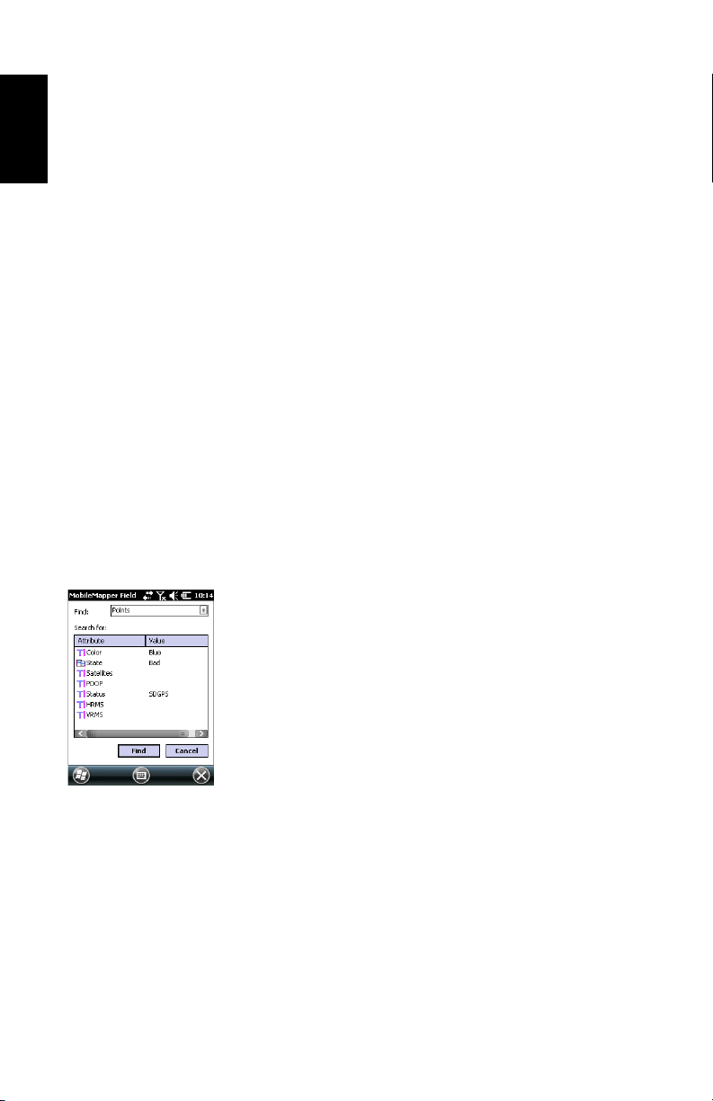
English
Editing a Feature When the map screen displays the feature you want to edit
and you know which changes need to be made to its
attributes, do the following.
• Tap on the feature symbol.
• When you see a bold orange line surrounding the feature,
release the stylus. The program then displays the list of
attributes pertaining to the feature.
• Edit the attributes that need changes and then tap OK. In
the case of a point feature, you are also allowed to update
its position by tapping on the Update button located in the
lower bar. Before tapping on this button, make sure you
are located exactly over this point as this will launch a new
position averaging sequence for your receiver’s current
position.
Find Feature
Function
MobileMapper Field allows you to search for a particular
feature you logged in a map. MobileMapper Field will ask you
to indicate the layer it belongs to, and optionally, the known
value of one or more of its attributes. As a result,
MobileMapper Field will list all the features meeting your
requirements.
• Tap Menu>Find.... MobileMapper Field displays one of the
layers present in the map as well as the names of the
different attributes attached to that layer.
•In the Find field, select the layer type of the feature you
are searching for.
• Optionally, tap on each of the attributes for which you
want to define a specific search criterion and then enter it.
• Tap on the Find button to start the search. MobileMapper
Field will list all of the features in the map which meet the
search requirements.
From this list you select the desired feature and see where
this feature is located on the map screen. In addition, by
selecting Menu>Go To..., MobileMapper Field will give you
the option of navigating to this feature.
36
Page 45

Upload/Download Functions
Using the USB data cable provided with your receiver, you
can exchange data between the receiver and your office
computer.
With Windows 7 or Vista running your computer, no particular
settings are required. With Windows XP (or older), use the
following settings in ActiveSync to make the connection
automatic at receiver power up:
Use the procedure below to copy files from one unit to the
other:
• MobileMapper 100 or 120:
– Place the receiver on the docking station
– Connect the docking staon to your office computer
using the USB data cable.
• MobileMapper 10:
– Connect the receiver to your office computer using the
USB data cable.
English
• Turn on the receiver.
• Wait until the connection is active.
• Do the following, depending on the OS used in your
computer:
– (Vista) In the auto-run window that opens, choose the
option to explore the mobile device
– (Windows XP or older) In the ActiveSync window, click
Explore.
• From either of these windows, you can copy any file from
the receiver to any folder on your office computer, or the
other way around, using the usual copy, paste and browse
functions.
37
Page 46

Coordinate Systems
English
Choosing a
Coordinate System
When creating a new DXF job or when creating a layer as the
first layer in a new *.map job, MobileMapper Field asks you
to define a coordinate system.
Proceed in this order:
1. Choose the World Geodetic System or the country where
your field operations will take place
2. In the field just underneath, choose the datum used
3. In the field just underneath, choose the projection used.
4. Choose the vertical datum in the last field. The default
possible choices are:
– Ellipsoid: Each altitude or height value is simply
determined with respect to the selected ellipsoid
(second field above).
– EGM84: Each altitude or height value is still initially
determined with respect to the selected ellipsoid but a
correction is applied to that value. The correction is
read from the EGM84 geoid (Earth Geoid Model 1984,
a global geoid model) and is specific to the computed
horizontal position.
38
Other geoid models may be downloaded to the receiver via
the MobileMapper Software CD from our website. Once
downloaded, they are made available as possible choices
in the Vertical Datum field.
The Properties... button at the bottom of the screen allows you
to view the properties of the selected datum and projection.
The New... button at the bottom of the screen allows you to
create a user system (datum + projection).
Page 47

Defining a User
System
• Tap on the New button.
• Select the type of projection you wish to use in your
coordinate system. Depending on that choice, you will
have to enter a certain number of parameters.
Remember every time you create a new projection and you
have to enter the latitude and longitude of origin, or the
central meridian, these must be expressed in degrees with
eight decimal places (ddd.dddddddd). On the other hand,
false eastings and false northings should always be
expressed in meters, even if a different unit has been
selected in the Units field on the same screen.
• After you have named and defined your new projection
and datum, just tap OK to save the new system and choose
it as the system used in the current job. This will take you
back to the coordinate system selection screen on which
you will now be able to see how the new USER coordinate
system has been defined (new projection and datum
names displayed in the second and third fields
respectively).
English
Viewing the
Properties of the
Coordinate System
Used in a Job
• Tap Menu>Job>Properties.
• Tap on the Coordinate System... tab. The screen now shows
the non-editable settings for the coordinate system used
in the map. Tap on the Properties button to read the details
of the datum and projection used in the coordinate
system.
39
Page 48

GNSS Toolbox
English
GNSS Toolbox is a software application that is separate from
MobileMapper Field. It is used to control and monitor GNSS
reception in MobileMapper 6.
From the Start screen, tap on the GNSS Tool Box icon or tap
on GNSS Tool Box on the Today screen. This opens the tool
box main menu in which four options are listed:
• GNSS Settings
•GNSS Status
• Reset
• About
GNSS Settings
•Open the GNSS Tool Box and double-tap on GNSS Settings.
This opens a new window where you can make the
following settings:
– Tracking mode: Only GPS L1 is available with
MobileMapper 6.
– Use SBAS check box: Check this box to enable SBAS
reception. When this box is cleared, SBAS reception is
disabled.
• Tap ok to confirm your choices and return to the GNSS
Tool box main menu.
GNSS Status •Open the GNSS Tool Box and double-tap on GNSS Status.
This opens a three-tab window.
The default Position tab shows the three coordinates of the
current position, as computed by the receiver, as well the
number of satellites used, the current PDOP value and the
position computation mode used.
40
Page 49

The unit used to express the current altitude (meters or
feet) depends on the region (language and country) you
selected in Start>Settings>System tab>Regional Settings.
•The Satellites tab displays a polar diagram showing the
locations in the sky of the tracked satellites.
•The Signal tab shows the signal level for each of the
tracked satellites. Green-blue bars indicate satellites used
in position computation. Grey bars only indicate satellites
being received but not used. Red bars on the right
indicate the SBAS satellites that are currently used.
GPS satellites are numbered from 1 to 32. Usually, SBAS
satellites are numbered from 120 to 138.
Reset •Open the GNSS Tool Box and double-tap on Reset. A
message directly asks you if you want to reset the receiver
now. Use this option only if you think the receiver is not
working properly.
English
41
Page 50

Post-Processing Option and MobileMapper Office
English
Unlocking the
Post-Processing
Option in the
Receiver
This is done by entering the POPN that was emailed to you
after you purchased the option.
• In the email containing the POPN, click on the link
provided. This takes you to a web page on the Spectra
Precision website from which you are invited to unlock the
post-processing option in your receiver.
• Connect the handheld receiver to your computer through
a USB connection and turn it on. Wait until the
connection is active.
• Go back to the computer and click on the link provided on
the web page. This installs/launches the Option Manager
utility program.
• Click Next>.
• Enter the POPN provided in the email.
• Click Next>, then click Finish twice. The post-processing
option is now unlocked and ready for use.
Logging Raw Data Here are a few key points that will help you understand how
the raw data logging function operates in your receiver.
• A raw data file is created per job. It is saved in the same
folder as the job file.
•With the Record raw data for post-processing option on, raw
data logging will start automatically when enough
satellites are received (>3). Raw data logging is effective
when “REC” is displayed in MobileMapper Field’s status
bar (see Getting Started With MobileMapper Field on
page 4).
NOTICE. It is a good practice to wait about 1 minute from
the time at least 4 satellites are received and the PDOP is
less than 3 before you start logging your first feature. (You
don’t need to be static during this wait time). The amount
of extra raw data will advantageously be used in
MobileMapper Office to secure the post-processing of your
features.
• MobileMapper 100 or 120 raw data files are named as
follows:
xnnnnsyy.ddd
42
Page 51

Where:
Parameters Description
x
nnnn Last four digits of the receiver serial number
s
yy Last two digits of year (“08” for 2008)
ddd Day number in year (1-366)
“A” for A-files (Auxiliary Coordinate files), or “G” for Gfiles (ATOM raw data files)
Session number (A, B, C,... X). Incremented every time
a new working session is created on the same day.
NOTE: The auxiliary coordinate file created during a
working session uses the same naming convention. Only
the prefix is different (“A” instead of “G”).
• MobileMapper 10 and MobileMapper 6 raw data files are
named as follows:
nnnnyymmddss.grw
Where:
Parameters Description
nnnn Last four digits of the receiver serial number
yy Last two digits of year (“08” for 2008)
mm Current month number (1-12)
dd Current day number (1-31)
ss
grw File extension
Session number, starting from 00. May consist of more
digits, if necessary.
English
NOTE: The coordinates file created during a working
session uses the same naming convention. Only the
extension is different (”crw” instead of “grw”).
• During raw data collection, even if you are not logging any
feature but just moving from one feature to another,
remember you should keep holding the receiver at an
angle of 45° above the horizontal.
• Never switch the receiver to suspend mode while
collecting raw data (this would end raw data collection). If
you want to save battery power while collecting data, you
may turn off the screen backlight. However, if you are also
using the e-compass while collecting raw data, remember
the backlight setting must be left unchanged. It must stay
as was set when you last calibrated the e-compass.
• Always collect raw data for at least 10 minutes, including
for those projects where GIS feature collection can be
completed in less time. Remember the more you collect
43
Page 52

English
raw data for a given project, the better the results of the
post-processing will be.
• Coming back to Menu>Options, Recording tab after starting
logging raw data allows you to read the name and path of
the raw data file being created. This information appears
underneath the Record raw data for post-processing option.
• A warning message will pop up if the memory goes low
while collecting raw data.
Installing
MobileMapper
Office Software
Post-Processing
With Mobile-
Mapper Office
Software
• Insert the installation CD in your computer. Wait until the
welcome screen is displayed.
• Click on Install MobileMapper Office. The installation
program starts analyzing the configuration of your
computer.
• The installation program may ask you to install one or
several Microsoft applications on your computer. If this
happens, please accept. These are:
– Microsoft .NET Framework 2.0
– Microsoft Visual C++ Runtime Libraries
– Microsoft Windows Installer 3.1
• The installation program then installs MobileMapper
Office.
• At the end of the installation, click Finish to quit the
installation program.
• Using the data transfer procedure (see Upload/Download
Functions on page 37), copy the following field data files
from the receiver to a folder of your choice on the
computer:
– *.map files
– *.shp files
– img*.jpg files
– sound*.wav files
– G* (MobileMapper 100 or 120) or *.grw (Mobile-
Mapper 10 or MobileMapper 6) raw data file.
– A* or *.crw file relevant to the downloaded G* or *.grw
file respectively.
• Run MobileMapper Office on your computer.
The program first displays a window allowing you to
quickly create a new project (a map file).
44
Page 53

Just give your project a name and indicate where to store
it and the program will automatically create the file
structure for the project. If you want to open an existing
project, click Cancel and then use button [1] below to
select Open and browse your computer for the existing
project. Next time you launch MobileMapper Office, the
last opened project will automatically re-open.
The MobileMapper Office main window looks like this:
English
45
Page 54

English
[4] [5]
[6]
[1]
[2]
[3]
The different areas are described below:
– [1]: Open/Create Map button
–[2]: Menu bar
– [3]: MAP filename and Layers list
– [4]: Map screen showing the content of the open
project, Also includes zoom buttons on the left and
distance/angle/area tool buttons on the right.
– [5]: Depending on what is currently selected in area
[3], [4] or [6], this area shows project properties
(coordinate system and units used), layer attributes
and appearance, or raw data file properties
(observation time span, etc.). When selecting a feature
on the map screen, the sound and image attributes
pertaining to the feature can be heard and viewed by
clicking on the three dots button after the file path in
the corresponding field. Clicking on this button will
start your computer’s default editor used for
respectively WAV and JPG files.
46
Page 55

– [6]: Observation times covered by the raw data files
added to the project. A blue bar stands for a receiver
raw data file, and a yellow bar, for a base raw data file.
• Click and select Open. Browse to the folder
containing your field data files.
• Select the Map file and click Open. MobileMapper Office
shows the content of the project in areas [3], [4] and [5]
(see screen above).
• Click on Add Rover Raw Data. Select the raw data file
corresponding to the project (from the same folder as
previously) and click Open. MobileMapper Office imports
the *G or GRW file and then shows the file properties in
areas [5] and [6].
• Assuming you are working with a third-party reference
station, click successively on Add Reference Raw Data then
From Web (your computer is supposed to have an Internet
connection). A new window then opens in which you have
to indicate how you wish to search for the reference
station you will use for post-processing your project.
English
• Choose one of the following two search criteria:
– Search up to x stations: Specify a preset number of
stations you want to list before choosing one. All the
listed stations will be the closest to your working area,
but there is no range limit for these stations.
– Search up to x km: Specify a limit of distance between
your working site and the stations. The shorter the
distance, the better the raw data from the station, but
the smaller the number of stations that can potentially
be used.
47
Page 56

English
• Click Search, then wait until the search is complete. At the
end of the search, MobileMapper Office lists the stations
meeting the search request.
• Select the most suitable reference station, mainly
according to the distance (baseline) to that station.
• Click Download. MobileMapper Office imports the base
raw data and then show its properties in areas [5] and [6].
NOTE: Spectra Precision does not guarantee 100%
quality results when using raw data files from reference
stations that are situated beyond 200 km (125 mi) from
your working area. It is also important to check that the
downloaded base data offer at least the same type of raw
data as the rover. If for example, the rover data are GPS/
GLO L1 data, then the base data should be at least GPS/
GLO L1 data. The post-processing may otherwise be
degraded to a certain extent.
• Click on Start Processing. MobileMapper Office post-
processes the different files present in the project. Below
is an example of what can be seen in the Layers pane at
the end of the post-processing step:
48
Page 57

For each layer (<Layer_name>) present in the project
MobileMapper Office has created two extra layers:
– <Layer_name> (Final): This layer is viewed by default. It
shows all the features of the <Layer_name> layer,
namely those that have just been post-processed, for
which you can now see the refined positions on the
map screen, and also those not impacted by the postprocessing, whose positions are unchanged compared
to what they are in the initial <Layer_name> layer.
– <Layer_name> (Post-processed): This layer is not viewed
by default. It only contains the features that were
actually post-processed. You may choose to only view
this layer if you wish to focus on the sole postprocessed features.
(The “initial”<Layer_name> layer is also hidden by
default.You may want to view this layer to see all the
features as they were before the post-processing step.)
MobileMapper Office has also added two different vector
layers to the project. Each vector describes the conditions
in which the baseline between each post-processed point
and the base station used has been determined. The
resulting components of the vector are also provided. The
two vector layers are:
• Vectors (QC Passed) (in green): The vectors pertaining to
that layer meet all the quality control parameters
defined on the Options tab (see Quality Control in Post-
Processing on page 50).
• Vectors (QC Failed) (in red): None of the vectors
pertaining to that layer meets the quality control
parameters defined on the Options tab. If the layer is
empty (no red vectors), then that means all the points
were post-processed successfully.
English
49
Page 58

English
Each vector can be edited individually. Just select one on
the map screen and the properties of the vector will then
appear In the right-hand pane (see example below).
All new layers have been created –and can be found– in
the same folder as those initially found in the project.
NOTE: DXF and AXF job files, MIF and CSV layers are not
supported in this version of MobileMapper Office.
Quality Control in
Post-Processing
You can place a quality control filter through which
MobileMapper Office will rate the post-processing results
according to your own requirements. Following the postprocessing of your project, MobileMapper Office will
associate the resulting vectors to two different layers: one
containing the vectors that passed the quality control (green
vectors), and a layer containing those that failed (red
vectors).
• Click and then on the Options button located in the
lower-right corner of the pop-up window.
• Enter your three quality control settings, i.e. the maximum
permitted values for HRMS, VRMS and PDOP. (see screen
example below).
50
Page 59

• Click OK to confirm your filter settings.
All the vectors for which the HRMS, VRMS and PDOP are
less than those specified here will pass the quality control
whereas all the others, if any, will fail.
Note that the quality control filter is applicable to all the
projects you open in MobileMapper Office, until you
modify the filter settings. To remove the filter, you just
need to set the three fields blank and click OK.
Note also that the PDOP characterizes each point when it
was logged (the PDOP is re-calculated by MobileMapper
Office, based on the content of the job file). In contrast,
the HRMS and VRMS are part of the post-processing
results and characterize the post-processed positions.
Export Function MobileMapper Office can export the visible layers from the
open project to three different formats:
• GPS exchange format (*.gpx). ALl the selected layers will
be merged into a single gpx file. Point features will be
converted into waypoints, lines and polygons into tracks.
• Google Earth format (*.kml). All the selected layers will be
merged into a single kml file.
Opening a kml file from the Google Earth initial view will
cause the Earth representation to be gradually rotated and
zoomed in to show the exact location of the features held
in the kml file.
English
51
Page 60

English
• ASCII format (*.csv). Each selected layer will result in a
separate csv file.
Follow the instructions below to export layers:
• Open your project.
• Make visible the layers you want to export (turn on the
corresponding check boxes). As background maps will not
be exported, they can stay visible in the project.
52
Re-Project
Function
• Click on and then select the format and destination
of the file(s) generated by the Export function.
• Click Save to complete the Export sequence.
MobileMapper Office can convert the entire content of a
project into another project, with all the original coordinates
converted to another coordinate system.
• Open the project you want to convert
• Click and then select Reproject As.
• Define the coordinate system in which to convert the
entire project. This definition includes the choice of the
Page 61

linear unit used to express all the coordinates (meters,
feet or survey feet), then click OK.
• Then name the resulting project (this will automatically
define a subfolder for this new project) and click OK. Wait
until the conversion is complete. MobileMapper Office
then shows the newly created project.
English
More About
MobileMapper
Office
• Undo Post-processing: If the post-processing results do
not meet your expectations, you can reverse to the original
SHP files by selecting the Undo Processing command.
• Zoom settings: In addition to the zoom buttons in the
menu bar and on the map screen, MobileMapper Office
offers another useful way of adjusting the zoom setting.
Double-click on a feature in the map screen. This takes
the feature to the center of the map screen. You can then
adjust the zoom setting around the feature, which stays at
the center of the screen, using the mouse wheel (turn
forward to zoom in, turn backward to zoom out).
• Viewing the background map: Background maps are seen
as layers in the project. Use Add Layer>Select Existing. In
the Open dialog box, choose “Raster file” as the file type
and then select the background map file. MobileMapper
Office supports the following raster formats: bmp, gif, tif,
jpg, jp2 and ecw. Select a raster file and click Open.
If this is the first layer inserted in the job, MobileMapper
Office will ask you to define the coordinate system used.
At this point, you can choose the linear unit used in the
coordinate system (meters, feet or survey feet).
If a layer already exists in the project when you import a
raster layer, there may be a message warning you about
the coordinate system used by the background map, if not
exactly the same as the one used in the layer. You may
choose to go on anyway if the two systems are not very
different. If you accept a background map using a very
different coordinate system, its resulting location on the
map screen will be inaccurate.
• Status Bar: The status bar is located at the bottom of the
main window. Whatever the feature selected on the map
screen, the status bar displays the coordinates of the
selected point.
For a line or polygon feature, the status bar additionally
shows a sliding bar allowing you to move the cursor on the
map screen from one point to the next or previous point
using respectively the “plus” or “minus” button at the two
ends of the sliding bar.
53
Page 62

English
The location of the cursor on the sliding bar is
representative of the position of the selected point in the
line or polygon.
• Layer Editor: MobileMapper Office also allows you to edit
SHP files in a way much similar to MobileMapper Field's
Edit/Create Layer function.
– When creating a new layer from scratch in
MobileMapper Office, a new window will open (see
below) asking you to define attributes for the new layer.
If you are familiar with creating attributes in
MobileMapper Field, using this window will be no
problem.
54
– Selecting a layer in the left-hand pane allows you to
read or change the visual aspect of all the features
pertaining to that layer (features shown in the central
pane, if any) and read the details of each of its
attributes in the right-hand pane.
– Selecting a feature in the central pane allows you to
read the values of its attributes in the right-hand pane.
Page 63

• Measuring distances, angles and areas on the map screen:
Use the three icons in the right-upper corner. The upper
one is for distances, the second one for areas and the
lower one for angles.
For each tool, the first click on the icon will activate the
tool and change the cursor shape. The second click will
turn off the tool and the cursor will recover its initial
shape. You may also press the right-hand mouse button to
deactivate the tool.
Distance measurement:
– Click on the first point from where to start the distance
measurement.
– Click on the second point defining the first measured
segment. Any new click on the map will create a new
segment from the previous point. From the second
point, the indicated distance value stands for the total
distance measured from the start point.
– Anticipate the end of measurement by double-clicking
on the last point. This will freeze the distance
measurement.
English
– Click on to quit the distance measurement tool.
Area measurement: Same as distance measurement. The
area measurement is effective only after you have defined
three points on the map. The value of perimeter is also
provided.
Angle measurement:
– Click successively on the first then on the second point
defining the segment providing the reference
direction. The tool then draws the angle measured and
gives its current value as you move the mouse cursor
on the map screen. If you click anywhere, the tool
freezes on the angle defined by this last click and gives
its value.
55
Page 64

English
– Click on to quit the angle measurement tool.
• Deleting a Feature: Select a feature on the map screen
that you want to delete, and then click on the Delete button
in the menu bar. Click Yes to confirm that you want to
delete this feature.
• Adding base raw data from a file: This function is
convenient when the useful base raw data files have
already been downloaded from the Internet or if they come
from a reference station that is not connected to the
Internet. In either case, click on Add Reference Raw
Data>From File and select the base raw data files.
• Editing the Coordinates of the Base Station Used: You
may need to edit the coordinates of the base station before
starting the post-processing. As shown on the screen
below, just click in the row (in the lower panel ([6])
containing the base data file. You can then edit the base
coordinates in the right-hand panel ([5])
56
• Removing a layer from a map: Select the layer in area [3]
on the screen and press the Del key or click on Remove
Layer.
• Shortcuts: From Windows Explorer, double-clicking a map
file (*.map) will directly open the file in MobileMapper
Office. All the files that can potentially be layers in
MobileMapper Office can be dragged & dropped in the
open map file (equivalent to selecting Add Layers>Select
Existing)
Page 65
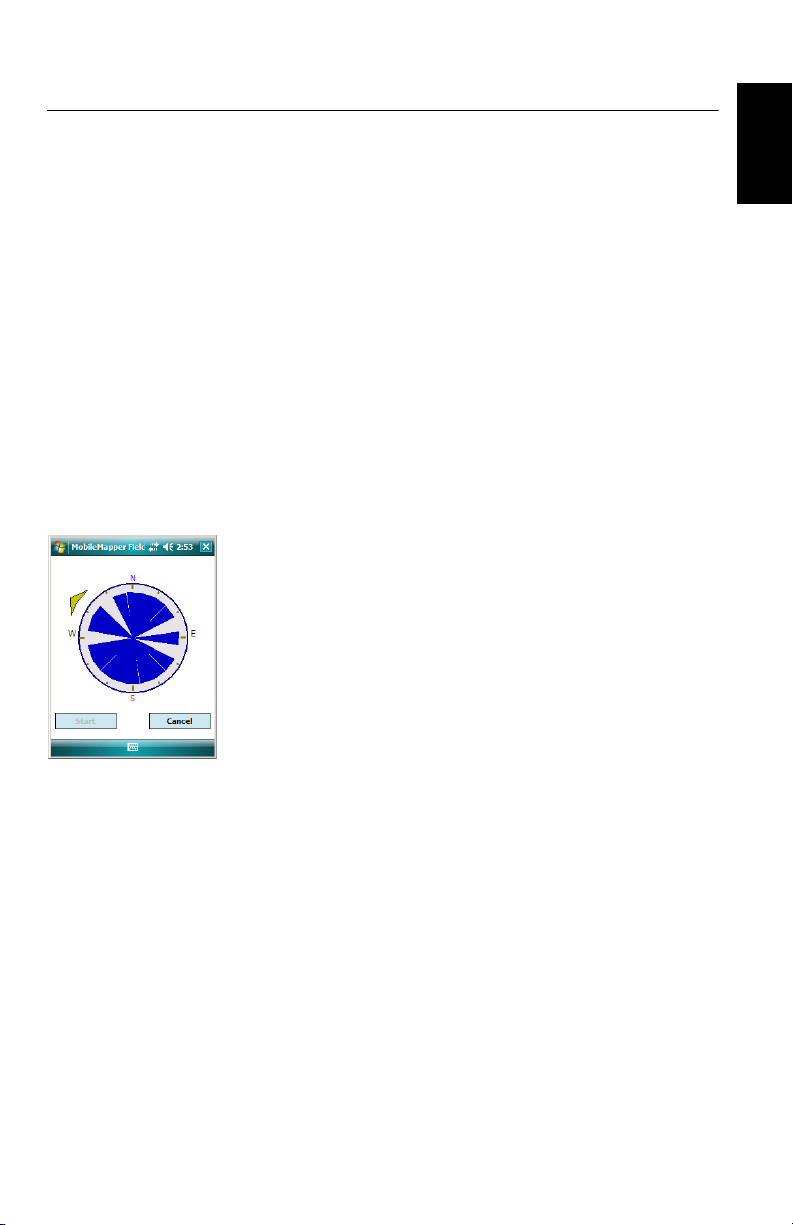
E-Compass & External Device
Enabling/Disabling
the E-Compass
Calibrating the E-
Compass
• Tap Menu>Options.
• Tap on the right-arrow button several times until you
unveil the E-compass and External Devices tabs.
• Tap on the E-compass tab.
• Set the Use electronic compass to determine orientation
button to enable or disable the E-compass. The compass
calibration is described in the section below.
Calibrating the E-compass is a two-step process during which
you are asked first to rotate the receiver anticlockwise in
horizontal position and then turn the unit upside down until
a beep is heard.
This procedure should be run with the receiver powered from
its internal batteries rather than an external power source.
• Tap on the Calibrate button.
• Read the instructions and then tap on the Start button.
• Wait until the arrow outside of the compass starts rotating
slowly clockwise. Rotate the receiver anticlockwise in
order to maintain the arrow in your direction. You will have
to perform three to five rotations until the inside of the
compass is completely dark blue. Try to be as accurate as
possible as this will speed up the calibration process.
Note that the arrow momentarily stops every 30 degrees or
so before continuing its rotation.
• When the inside of the compass is all dark blue and after
the arrow has come back to the South direction, a
message asks you to proceed with the last step of the
calibration.
• Tap ok in the message window and turn the receiver
upside down on a horizontal surface. Wait a few seconds
until a beep can be heard.
• Put the receiver the right way up. A message on the screen
indicates that the calibration is complete and successful.
• Tap ok in the message window. This takes you back to the
E-compass tab of the Options screen.
• Tap ok to return to the map screen.
English
57
Page 66

Recommendations
English
for E-Compass
Calibration
The E-compass being a very sensitive sensor, Ashtech
recommends you adhere to the following recommendations.
• Calibration should always be performed:
– Outdoor, not indoor.
– On a flat horizontal surface, not in your hands.
– From within MobileMapper Field rather than from
within MobileMapper Today.
– In the same operating conditions (i.e. same backlight
level, with/without SD card) as those you will work in
later when you collect your GIS data.
For screen backlight, this means the two options
controlling the backlight function on the Battery Power
tab of the Settings window must be cleared for the
calibration phase, but also as long as you need to use
the e-compass. (The Settings window is accessible from
the third icon on the MobileMapper Today toolbar or
through Start>Settings>System tab>Brightness icon)
• During calibration, make sure all compass sectors become
dark blue.
• Always recalibrate the E-compass in the following cases:
– After changing the batteries.
– Whenever you suspect the E-Compass to deliver
incorrect values.
E-Compass Vs.
GPS Compass
58
In fact, the receiver has two compasses:
•The e-compass. which can be used independently by
MobileMapper Field and MobileMapper Today. It can even
be used by both at the same time.
•The GPS compass, which is the default compass used by
MobileMapper Field when the e-compass is not activated.
(The GPS compass information is a by-product of the GPS
position computation.)
Follow the recommendations below to know which compass
should be used, depending on what you are doing:
• Measuring bearings with the E-compass requires that the
receiver be held in horizontal position. On the other hand,
the GPS sensor requires that the receiver be held at an
angle of 45° from the horizontal. A good compromise is
therefore to orientate the receiver 20 to 25° from the
horizontal. If the bearing measurement is most important
to you, you can temporarily place the receiver horizontal
until you get a valid bearing measurement.
Page 67

• Using the E-compass is recommended for static
occupations (lines/areas in vertex mode and points). The
GPS compass is recommended for trajectories (lines/areas
logged in automatic time or distance mode).
• E-compass readings stabilize after a few seconds. When
logging a point feature after a walking period, please hold
the receiver horizontally and wait a few seconds before
starting logging the feature.
• Tagging a picture file with bearing information: After
taking the picture, you should hold the receiver horizontal
for a few seconds before saving the picture. This will allow
the E-compass to deliver a valid bearing measurement.
English
Setting an External
Device
After establishing a Bluetooth connection with the external
device used in conjunction with your receiver, do the
following:
• Tap Menu>Options.
• Tap on the right-arrow button several times until you
unveil the External Devices tab.
• Tap on the External Devices tab.
•In the Ty pe field, select the name of your external device
(3M Dynatel Locator or LTI TruPulse 360).
• Set the virtual port number and baud rate used to let your
receiver communicate with this device.
• Tap ok to enter your settings and return to the map screen.
59
Page 68

Voice Setting
English
For best quality voice recording, you need to change the
default voice sampling setting as follows:
• From the Start button, select Programs.
• Double-tap the Notes icon. If this action directly opens a
note file, please close it before proceeding.
• Tap Menu>Options.
• Tap on the Global Input Options hyperlink.
• Tap on the Options tab.
• Select “44,100 Hz, 16 Bit, Mono (86 KB/s)” from the
Voice recording format drop-down list.
• Tap ok to enter the new setting.
• Tap ok twice to return to the Today screen.
60
Page 69

Installing MobileMapper Office Software
• Insert the installation CD in your computer. Wait until the
welcome screen is displayed.
• Click on Install MobileMapper Office. The installation
program starts analyzing the configuration of your
computer.
• The installation program may ask you to install one or
several Microsoft applications on your computer. If this
happens, please accept. These are:
– Microsoft .NET Framework 2.0
– Microsoft Visual C++ Runtime Libraries
– Microsoft Windows Installer 3.1
• The installation program then installs MobileMapper
Office.
• At the end of the installation, click Finish to quit the
installation program.
English
61
Page 70

Index
(Final) 49
English
(Post-processed) 49
Symbols
*.dxf file 1, 9
*.map file 1, 9, 44
*.shp files 44
A
ActiveSync 2, 37
Add Reference Raw Data 47
Add Rover Data 47
Age of corrections 5
Area 17
Area units 7
Attributes 16, 28
Averaging 27
Axf 11, 50
B
Background map 1, 20
Base station (change coordinates) 56
C
Change Coordinates (base station) 56
Color 16
Coordinate system 1, 14, 38
Coordinates (base station) 56
Course up 7
Crw files 43, 44
CSV 13, 19, 52
D
Date 17
Datum 14, 38
Dbf 10
DBF files 1
Delete feature 56
Dfs 10
DGPS 4
Double-logging 32
Download 37
Drag map 6
Drw 10
Duration of data collection 43
DXF 13
E
E-compass 26
E-compass (calibrate) 57
E-compass (enable/disable) 57
Edit Coordinates (base station) 56
Enter target coordinates 35
ESC key 6
Export function 51
External device 59
F
Features 1, 5, 36
Fill 16
Filter 6
Filter settings (quality control) 51
Find feature function 36
FIXED 4
FLOAT 4
Framework 2.0 44, 61
Freezing layer definition 15
G
Georeferenced file 21
GeoTIFF 21
GIF 21
GNSS Service (turning it off) 2
GNSS settings 40
GNSS Toolbox 40
Go to 35
Google Earth 51
GPS compass 26, 58
GPX format 51
Grw files 42, 43, 44
H
HRMS 5, 51
I
Image 17
Image file 21
img*.jpg files 44
Incompatible layer 19
Initialize 5
Install MobileMapper Office 44, 61
J
Job 1
Job file name 9
Job properties 11
JPEG 21
JPEG2000 21
K
Keyboard (large one) 7
Keyboard (virtual) 5
Kml file format 51
L
Label 18
Layer 1, 5, 10, 13, 21
Layer (add) 19
Layer properties 15
Length 17
Line feature 28
Linear units 7
Log 5
Page 71

Log raw data 42
M
Main memory 9, 14
Mandatory attribute 16, 18
Map file 5, 25
Map screen 1, 6, 28
Menu 16
MIF 13, 19
Minimizing MobileMapper Field 8
Mnd 10
Mnu 10
MobileMapper Office 1, 44
N
North up 7
Numeric 17
O
Observation times 47
OSM (OpenStreetMap) 20
P
PDOP 5, 6, 7, 25, 40, 51
Perimeter 17
Picture 17
Point feature 26
Polygon feature 28
POPN 3, 42
Post-processing 1
Prj 10
Projection 14, 38
ProMark3 56
Q
Quality control 50
R
Raw data recording 1
REC 5, 42
Repeat attributes 33
Re-project function 52
Reset 41
S
SBAS 4, 5
Scale 5, 6, 18
SDGPS 4
Search up to x km 47
Search up to x stations 47
Show/hide features 18
Show/Hide Layer 15
SHP 1, 13, 14, 19, 21
Shp 10
SHP files (M-type) 19
SHX 1
Shx 10
Sound 17
Start (post-processing) 48
Storage Card (SD card) 9, 14
Style 16
Symbol 16
T
Target coordinates 35
Templates 11
Text 16
Type (of feature) 14
U
Update location 36
Upload 37
USB 1, 37
Use electronic compass to determine
orientation
57
V
VDOP 51
Vectors (QC Failed) 49
Vectors (QC Passed) 49
Vertical offset 25, 26, 29
Vista 2, 37
Visual C++ runtime libraries 44, 61
Voice 17, 30
Voice guidance 5, 35
Voice setting 60
VRMS 5, 51
W
WAV files 31
Windows Installer 3.1 44, 61
Windows Mobile Device Center 2
Windows XP 2, 37
Y
Yes/No 17
English
Page 72

MobileMapper Field & Ofce Software
Getting Started Guide
Contact Information:
AMERICAS
Spectra Precision Division
10368 Westmoor Drive
Westminster, CO 80021, USA
www.spectraprecision.com
©2012-2014 Trimble Navigation Limited. All rights reserved. Spectra Precision is a Division of Trimble Navigation Limited. Spectra Precision and the
Spectra Precision logo are trademarks of Trimble Navigation Limited or its subsidiaries. P/N 631655-01E
EUROPE, MIDDLE EAST AND AFRICA
Spectra Precision Division
Rue Thomas Edison
ZAC de la Fleuriaye - CS 60433
44474 Carquefou (Nantes), France
ASIA-PACIFIC
Spectra Precision Division
80 Marine Parade Road
#22-06, Parkway Parade
Singapore 449269, Singapore
 Loading...