

Page 1

Layout Pro Field Software
Quick Start Guide
Page 2

SOFTWARE END USER LICENSE AGREEMENT (EULA)
IMPORTANT, READ THIS AGREEMENT CAREFULLY. BY INSTALLING OR USING ALL OR ANY PORTION OF THE SOFTWARE, YOU ARE ACCEPTING
ALL OF THE TERMS AND CONDITIONS OF THIS
AGREEMENT. YOU AGREE THAT THIS AGREEMENT IS ENFORCEABLE LIKE ANY WRITTEN
AGREEMENT.
IF YOU DO NOT AGREE TO ALL OF THESE TERMS
AND CONDITIONS, DO NOT USE OR ACCESS THE
SOFTWARE.
IF YOU HAVE PAID A LICENSE FEE FOR USE OF
THE SOFTWARE AND DO NOT AGREE TO THESE
TERMS, YOU MAY RETURN THE SOFTWARE
(ALONG WITH ANY HARDWARE ON WHICH IT
WAS EMBEDDED, IF APPLICABLE) FOR A FULL
REFUND PROVIDED YOU (A) DO NOT USE THE
SOFTWARE AND (B) RETURN THE SOFTWARE
WITHIN THIRTY (30) DAYS OF YOUR INITIAL PURCHASE.
IF YOU WISH TO USE THE SOFTWARE AS AN EMPLOYEE, CONTRACTOR, OR AGENT OF A CORPORATION, PARTNERSHIP OR SIMILAR ENTITY,
THEN YOU MUST BE AUTHORIZED TO SIGN FOR
AND BIND THE ENTITY IN ORDER TO ACCEPT THE
TERMS OF THIS AGREEMENT. THE LICENSES
GRANTED UNDER THIS AGREEMENT ARE EXPRESSLY CONDITIONED UPON ACCEPTANCE BY
SUCH AUTHORIZED PERSONNEL.
IF YOU HAVE ENTERED INTO A SEPARATE WRITTEN LICENSE AGREEMENT WITH TRIMBLE FOR
USE OF THE SOFTWARE, THE TERMS AND CONDITIONS OF SUCH OTHER AGREEMENT SHALL PREVAIL OVER ANY CONFLICTING TERMS OR
CONDITIONS IN THIS AGREEMENT.
This End User License Agreement (“Agreement”) is
between Trimble Navigation Limited, located at 935
Stewart Drive, Sunnyvale, CA 94085, U.S.A. and/or
its Affiliates (“Tri mbl e”) and the customer (individual or entity) that has downloaded or otherwise procured the licensed Software (as defined below) for
use as an end user (“You ”). This Agreement covers
any Software and supporting technical documentation provided with the Software (“Documentation”).
1. Definitions
“Affiliate” shall mean any entity that directly or indirectly through one or more entities, controls, is controlled by, or is under common control with a Trimble
party. For purposes of this definition, the term "con-
trol" as applied to any entity, means the possession,
directly or indirectly, of the power to direct or cause
the direction of the management of that entity,
whether through ownership of voting securities or
otherwise.
“Effective Date” means the earlier of the date You
sign an Order Form or the date on which the Software
is first made available to You.
“Order Form” means any order which is entered into
by Trimble (or an authorized Trimble distributor or reseller) and You under which You are provided the
Software. Each Order Form for the Software shall be
deemed a part of this Agreement. This Agreement is
binding on You whether or not You executed an Order
Form with Trimble. Order Forms may not vary the
terms of this Agreement. Only a written agreement,
signed by Trimble (not a Trimble distributor or reseller) may vary the terms of this Agreement.
(TNL - TEBV)
“Software” means the Trimble software product(s)
provided in connection with this Agreement in object
code form (or as otherwise specified in any related
Order Form). “Software” shall also include any releases provided to or purchased by You under any
separate support and maintenance agreement You
may enter into with Trimble. Unless otherwise noted,
the Software and Documentation are referred to collectively herein as “Software”.
“Third-Party Software” means any third-party software that is provided to You by Trimble under this
Agreement or under separate terms and conditions.
“Trimble Supplier” means either Trimble or an authorized distributor or reseller of Trimble products or services which has entered into an Order Form with You.
2. License
2.1.Grant of License. Subject to all of the terms and
conditions of this Agreement, Trimble grants You a
non-transferable, non-sublicensable, non-exclusive
license to use the Software in machine-readable form
on any computer and operating system for which it
was intended, but solely (a) for your own internal
business purposes at the location specified in the applicable Order Form or otherwise agreed to by Trimble
(the “Site”); (b) in accordance with the Documentation; and (c) in accordance with any additional license term, subscription term or other user, seat,
computer, field of use or other restrictions set forth
in the applicable Order Form or otherwise specified
by Trimble.
2.2.Installation and Copies. Trimble shall make
available the Software and Documentation by disk,
other media, or as embedded in a device, or make it
available for download in electronic form. Trimble
shall also provide You with electronic passwords or
other enabling mechanisms if necessary to permit
the licensed usage of the Software. All licenses shall
commence, and delivery shall be deemed to occur, as
of the Effective Date (or, if later, such date on which
the Software and license keys are first made available to You). If your Order Form is with a Trimble distributor or reseller, that distributor or reseller (and
not Trimble) is solely responsible for delivery to You
and Trimble has no liability for any failure to deliver.
If the Software requires license keys to operate as licensed to You, the applicable Trimble Supplier will
deliver such license keys to You.
2.3.Software Intended to be Installed on Computers.
The Software is licensed as a single product. You may
not separate its component parts for use on more
than one computer except as specifically authorized
in this Agreement. You may copy and install on your
computers for use only by your employees the number of copies of the Software for which You have paid
the applicable license fee or have been authorized in
writing by Trimble. You may transfer the Software
from one computer to another computer provided
that the computer to which the Software is transferred is located at the Site and the Software is completely removed and de-installed from the prior
computer. If You are permitted by Trimble to install
the Software on a network server, and You transfer
the Software from the Site to a new location, You
must provide Trimble with written notice of the new
site prior to such transfer. You may also make a reasonable number of copies of the Software only for
back-up and archival purposes. This Paragraph 2.3
does not apply to any software embedded on Trimble
devices.
Page 3

2.4. License Restrictions.
2.4.1 You shall not (and shall not allow any third party to): (a) decompile, disassemble or otherwise reverse engineer the Software or attempt to reconstruct
or discover any source code, underlying ideas, algorithms, file formats or programming interfaces of the
Software by any means whatsoever (except and only
to the extent that applicable law prohibits or restricts
reverse engineering restrictions). To the extent any
applicable mandatory laws give You the right to perform any of the aforementioned activities without
Trimble’s consent in order to gain certain information
about the Software for purposes specified in the respective statutes (e.g., interoperability), You hereby
agree that, before exercising any such rights, You
shall first request such information from Trimble in
writing detailing the purpose for which You need the
information. Only if and after Trimble, at its sole discretion, partly or completely denies your request,
may You exercise such statutory rights; (b) distribute,
sell, sublicense, rent, lease or transfer the Software
(or any portion thereof), nor use the Software (or any
portion thereof) for time sharing, hosting, service
provider or like purposes; (c) provide the Software to
a third party on a temporary basis and/or use the
Software for the benefit or purposes of a third party
whether by means of lease, loan, data processing services (e.g. “fee for service”) or otherwise, unless You
are a reseller of Trimble products under separate written agreement with Trimble and authorized by Trimble to do so; (d) remove any product identification,
proprietary, copyright, or other notices contained in
the Software; (e) modify any part of the Software,
create a derivative work of any part of the Software,
or incorporate the Software into or with other software, except to the extent expressly authorized in
writing by Trimble; (f) attempt to circumvent or d isable the security key mechanism that protects the
Software against unauthorized use (except and only
to the extent that applicable law prohibits or restricts
such restrictions) and/or any licensing control features; or (g) publicly disseminate performance information or analysis (including, without limitation,
benchmarks or comparison testing or analysis) from
any source relating to the Software or disclose to any
third-party or release any results thereof (all of which
information shall be considered Trimble confidential
information) without Trimble’s prior written consent.
2.4.2 If the Software has been provided to You as
embedded in any hardware device, You are not licensed to separate the Software from the hardware
device. If the Software has been provided to You separately from a hardware device but is intended to be
loaded onto a hardware device specified by Trimble
(such as a firmware update), your license is limited
to loading the Software on the device specified by
Trimble in the Documentation, and for no other use.
2.4.3 You agree to use all reasonable efforts to prevent unauthorized use and disclosure of the Software.
2.5.Evaluation Software. Subject to the terms and
conditions of this Agreement and during its term,
Trimble may, in its discretion, provide You with prerelease, beta or other software on an evaluation basis
(“Evaluation Software”). You may use Evaluation
Software solely for internal evaluation purposes for
thirty (30) days from receipt of the Evaluation Software (unless otherwise agreed by Trimble in writing)
(the “Evaluation Period”).
Unless You pay the applicable license fee for the
Software, the Evaluation Software may become inoperable and, in any event, your right to use the Evalu-
ation Software automatically expires at the end of the
Evaluation Period. Evaluation Software shall be subject to all restrictions on Software set forth in this
Agreement. You shall treat all Evaluation Software as
Confidential Information of Trimble and shall return
or destroy any copies of Evaluation Software upon expiration of the applicable Evaluation Period. Any and
all suggestions, reports, ideas for improvement and
other feedback of any type You provide regarding the
Evaluation Software are the sole property of Trimble,
and Trimble may use such information in connection
with any of its products or services without any obligation or restriction based on intellectual property
rights or otherwise. You acknowledge that all Evaluation Software is provided “AS IS” and may not be
functional on any machine or in any environment.
THE WARRANTIES OF SECTION 5 DO NOT APPLY
TO EVALUATION SOFTWARE. TRIMBLE AND ITS
SUPPLIERS DISCLAIM ALL WARRANTIES RELATING TO THE EVALUATION SOFTWARE, EXPRESS
OR IMPLIED, INCLUDING, BUT NOT LIMITED TO,
MERCHANTABILITY, FITNESS FOR A PARTICULAR
PURPOSE, TITLE OR NON-INFRINGEMENT.
2.6.Internet-Based Services Components. Some features of the Software may require connection to the
Internet directly or through a wireless connection in
order to function. Such features may result in the
transfer of certain data over such connections, which
may or may not be secure or encrypted. You are solely
responsible for obtaining any necessary Internet
wireless subscription plans with the applicable service providers. You further acknowledge that Trimble
is not responsible for the availability of Internet or
wireless connections or the security or integrity of
data transmitted over such connections.
2.7 Ownership. Notwithstanding anything to the contrary contained herein, except for the limited license
rights expressly provided herein, Trimble, its licensors and suppliers have and will retain all rights, title
and interest (including, without limitation, all patent,
copyright, trademark, trade secret and other intellectual property rights) in and to the Software and all
copies, modifications and derivative works thereof
(including any changes which incorporate any of your
ideas, feedback or suggestions). You acknowledge
that You are obtaining only a limited license right to
the Software and that irrespective of any use of the
words “purchase”, “sale” or like terms hereunder no
ownership rights are being conveyed to you under
this Agreement or otherwise.
2.8 Copyright. All title, rights and copyrights in and
to the Software (including, but not limited to, any images, photographs, animations, video, audio, music,
and text incorporated into the Software, as well as all
intellectual property rights), the Documentation and
other accompanying written materials, and any copies of the Software are owned by Trimble, its licensors and/or suppliers. You shall not remove, cover, or
alter any of Trimble's patent, copyright, or trademark
notices placed upon, embedded in, or displayed by
the Software or on its Documentation, packaging and
related materials.
3. Payment
3.Payment. Unless a Software has been made available by Trimble at no charge, You shall pay all fees
associated with the Software licensed and any services purchased hereunder as set forth in the applicable Order Form. All payments shall be made in the
currency specified in the applicable invoice within
thirty (30) days of your receipt of such invoice, unless otherwise specified in writing by the Trimble
Supplier. Except as expressly set forth herein, all fees
Page 4

are non-refundable once paid. You shall be responsible for all taxes, withholdings, duties and levies arising from the order (excluding taxes based on the net
income of the Trimble Supplier). Any late payments
shall be subject to a service charge equal to 1.5%
per month of the amount due or the maximum
amount allowed by law, whichever is less.
4. Term of Agreement
4.1.Term. This Agreement is effective as of the Effective Date and expires at such time as all license
and service subscriptions hereunder have expired in
accordance with their own terms (the “Ter m”). Either
party may terminate this Agreement (including all
related Order Forms) if the other party: (a) fails to
cure any material breach of this Agreement within
thirty (30) days after written notice of such breach;
(b) ceases operation without a successor; or (c) seeks
protection under any bankruptcy, receivership, trust
deed, creditors arrangement, composition or comparable proceeding, or if any such proceeding is instituted against such party and not dismissed within
sixty (60) days. If You have entered into a separate
written agreement with Trimble which governs the
Software and that agreement is terminated, then this
Agreement automatically terminates and You shall no
longer have any right to use the Software. Termination is not an exclusive remedy and the exercise by
either party of any remedy under this Agreement will
be without prejudice to any other remedies it may
have under this Agreement, by law, or otherwise. For
clarity, even if You have entered into an Order Form
with a Trimble distributor or reseller, Trimble is a
third party beneficiary to that Order F orm and has the
right to terminate this Agreement as set forth in this
Section 4 (Term of Agreement).
If a Software has been made available by Trimble at
no charge, the license remains effective until terminated in accordance with subparagraphs (b) to (c)
mentioned above; You decide to terminate this
Agreement by ceasing all use of the Software and destroying or returning all copies; or, without prejudice
as to any other rights, Trimble decides to terminate
this Agreement with or without notice if You fail to
comply with the terms and conditions of this Agreement.
4.2.Termination. Upon any expiration or termination
of this Agreement, You shall cease any and all use of
any Software and Evaluation Software and destroy all
copies thereof and so certify to Trimble in writing.
5.3.Survival. Paragraph 2.4 (License Restrictions),
Paragraph 2.7 (Ownership), Paragraph 2.8 (Copyright), Section 3 (Payment), Section 4 (Term of
Agreement), Paragraph 5.3 (Disclaimer of Warranties), Section 8 (Limitation of Remedies and Damages), Section 9 (Confidential Information), Section 10
(Export Compliance) and Section 11 (General) shall
survive any termination or expiration of this Agreement.
5. Limited Warranty and Disclaimer
6.1.Limited Warranty. Trimble warrants to You that
for a period of ninety (90) days from the Effective
Date (the “Warranty Period”) the Software shall operate in substantial conformity with the Documentation. Because the Software is inherently complex and
may not be completely free of nonconformities, defects or errors, You are advised to verify your work.
Trimble does not warrant that the Software will operate error free or uninterrupted, that it will meet your
needs or expectations, that all nonconformities can
or will be corrected, or the results obtained through
use of the Software. Trimble’s sole liability (and your
exclusive remedy) for any breach of this warranty
shall be, in Trimble’s sole discretion, to use commercially reasonable efforts to provide You with an errorcorrection or work-around which corrects the reported non-conformity, or if Trimble determines such
remedies to be impracticable within a reasonable period of time, to refund the license fee paid for the
Software. A Trimble Supplier other than Trimble may
fulfill Trimble’s warranty obligations hereunder on
behalf of Trimble. Trimble Suppliers shall have no obligation with respect to a warranty claim unless notified of such claim within the Warranty Period.
5.2.Exclusions. The above warranty shall not apply:
(a) if the Software is used with hardware or software
not specified in the Documentation; (b) if any modifications are made to the Software by You or any third
party; (c) to defects in the Software due to accident,
abuse or improper use by You; (d) to Software provided on a no charge or evaluation basis; (e) to any Third
Party Software; or (f) to any Software obtained as
freeware, whether from Trimble, a Trimble Supplier
or otherwise.
5.3.Disclaimer of Warranties. THIS SECTION 5 IS A
LIMITED WARRANTY AND, EXCEPT AS EXPRESSLY
SET FORTH IN THIS SECTION 5, THE SOFTWARE
AND ALL SERVICES ARE PROVIDED “AS IS.” NEITHER TRIMBLE NOR ITS SUPPLIERS MAKES ANY
OTHER WARRANTIES, CONDITIONS OR UNDERTAKINGS, EXPRESS OR IMPLIED, STATUTORY OR
OTHERWISE, INCLUDING BUT NOT LIMITED TO
WARRANTIES OF TITLE, MERCHANTABILITY, FITNESS FOR A PARTICULAR PURPOSE OR NONINFRINGEMENT. YOU MAY HAVE OTHER STATUTORY
RIGHTS. HOWEVER, TO THE FULL EXTENT PERMITTED BY LAW, THE DURATION OF STATUTORILY
REQUIRED WARRANTIES, IF ANY, SHALL BE LIMITED TO THE LIMITED WARRANTY PERIOD. YOU
ASSUME THE ENTIRE RISK AS TO RESULTS AND
PERFORMANCE OF THE SOFTWARE. IN ADDITION, TRIMBLE MAKES NO WARRANTY, EXPRESSED OR IMPLIED, TO SOFTWARE PROVIDED
TO YOU FREE OF CHARGE INCLUDING WITHOUT
LIMITATION FOR ACCURACY, COMPLETENESS,
SUITABILITY, PERFORMANCE OR USE. ANY SOFTWARE PROVIDED AT NO COST IS PROVIDED BY
TRIMBLE "AS IS."; ALL IMPLIED WARRANTIES ARE
IN SUCH CASE DISCLAIMED
.
6. Support & Maintenance
Trimble shall provide the support and maintenance
services, if any, as separately purchased by You and
specified in the applicable Order Form. Such support
and maintenance shall be provided pursuant to Trimble’s standard service terms which are available upon
request from Trimble. Trimble Suppliers may provide
additional support services under separate written
agreement, but Trimble is not responsible for any
such support unless being a contracting party.
7. Professional Services.
The Trimble Supplier shall provide the number of
person-days, if any, of professional consulting services (“Professional Services”) purchased in the applicable Order Form and related statement of work. If
Trimble is providing Professional Services, unless
agreed in a separate written agreement, all Professional Services shall be provided pursuant to Trimble’s standard service terms which are available upon
request from Trimble. If your Order Form is with a
Trimble Supplier other than Trimble, that party (and
not Trimble) is solely responsible for providing Pro-
Page 5

fessional Services and Trimble, not being a contracting party, has no liability related to such services.
8. Limitation of Remedies and Damages.
8.1. NEITHER TRIMBLE NOR TRIMBLE’S SUPPLIERS SHALL BE LIABLE FOR ANY LOSS OF USE,
LOST DATA, FAILURE OF SECURITY MECHANISMS, INTERRUPTION OF BUSINESS, OR ANY
INDIRECT, SPECIAL, INCIDENTAL, OR CONSEQUENTIAL DAMAGES OF ANY KIND (INCLUDING
LOST PROFITS), REGARDLESS OF THE FORM OF
ACTION, WHETHER IN CONTRACT, TORT (INCLUDING NEGLIGENCE), STRICT LIABILITY OR OTHERWISE, EVEN IF INFORMED OF THE POSSIBILITY
OF SUCH DAMAGES IN ADVANCE.
8.2. NOTWITHSTANDING ANY OTHER PROVISION
OF THIS AGREEMENT, TRIMBLE AND ITS SUPPLIERS’ ENTIRE LIABILITY TO YOU UNDER THIS
AGREEMENT SHALL NOT EXCEED THE AMOUNT
ACTUALLY PAID BY YOU TO TRIMBLE UNDER THIS
AGREEMENT.
8.3. THE SOFTWARE IS NOT FAULT TOLERANT
AND IS NOT DESIGNED, MANUFACTURED OR INTENDED FOR USE IN LIFE SUPPORT, MEDICAL,
EMERGENCY, MISSION CRITICAL OR OTHER
STRICT LIABILITY OR HAZARDOUS ACTIVITIES
(“HIGH RISK ACTIVITIES”). TRIMBLE SPECIFICALLY DISCLAIMS ANY EXPRESS OR IMPLIED WARRANTY OF FITNESS FOR HIGH RISK ACTIVITIES.
YOU REPRESENT AND WARRANT THAT YOU WILL
NOT USE THE SOFTWARE (OR PERMIT IT TO BE
USED) FOR HIGH RISK ACTIVITIES, AND AGREE
THAT TRIMBLE WILL HAVE NO LIABILITY FOR USE
OF THE SOFTWARE IN HIGH RISK ACTIVITIES.
YOU AGREE TO INDEMNIFY AND HOLD HARMLESS TRIMBLE FOR ANY DAMAGES, LIABILITIES
OR OTHER LOSSES RESULTING FROM SUCH USE.
8.4. The parties agree that the limitations specified
in this Section 8 will survive and apply even if any
limited remedy specified in this Agreement is found
to have failed of its essential purpose.
9. Confidential Information.
Any software, Documentation or technical information provided by Trimble (or its suppliers and agents)
shall be deemed “Trimble Confidential Information”
without any marking or further designation. Except as
expressly authorized herein, You will hold in confidence and not use or disclose any Trimble Confidential Information. Without limiting the foregoing, You
acknowledge that the Software constitutes the valuable confidential information and trade secrets of
Trimble and, accordingly, You shall at all times, both
during the term of this Agreement and thereafter
keep in trust and confidence all the Software, and
shall not disclose the same to any third party without
Trimble’s prior written consent. You acknowledge
that disclosure of Trimble Confidential Information
would cause substantial harm to Trimble that could
not be remedied by the payment of damages alone
and therefore that upon any such disclosure by You,
Trimble shall be entitled to appropriate equitable relief in addition to whatever remedies it might have at
law.
10. Export Compliance
You agree to comply with all applicable laws and regulations of the United States of America (“U.S.”) and
of other jurisdictions (national, state, and local) to
the extent that they may govern your use of the Software. In addition, You acknowledge that the Software
may be subject to export restrictions by the U.S. government and by certain other governments. You shall
not, and shall not allow any third party to, directly or
indirectly, remove or export or allow the export or reexport of any part of the Software or any direct product thereof: (a) into (or to a national or resident of)
any embargoed or terrorist-supporting country; (b) to
anyone on the U.S. Commerce Department’s Table of
Denial Orders or U.S. Treasury Department’s list of
Specially Designated Nationals; (c) to any country to
which such export or re-export is restricted or prohibited, or as to which the U.S. government or any agency thereof requires an export license or other
governmental approval at the time of export or re-export without first obtaining such license or approval;
or (d) otherwise in violation of any export or import restrictions, laws or regulations of any U.S. or foreign
agency or authority laws, or in violation of any applicable export control laws in the country where the
Software has been obtained or is used. You agree to
the foregoing and warrant that You are not located in,
under the control of, or a national or resident of any
such prohibited country or on any such prohibited
party list. The Software is further restricted from being used for the design or development of nuclear,
chemical, or biological weapons or missile technology, or for terrorist activity.
11. General.
11.1. Assignment. This Agreement will bind and inure to the benefit of each party’s permitted successors and assigns. Trimble may assign this Agreement
to any Affiliate or in connection with a merger, reorganization, acquisition or other transfer of all or substantially all of Trimble’s assets or voting securities.
You may not assign or transfer this Agreement, in
whole or in part, without Trimble’s written consent.
Any attempt to transfer or assign this Agreement
without such written consent will be null and void. If
You obtain such consent from Trimble, You shall permanently assign or transfer all of your rights under
this Agreement, provided You retain no copies and
You transfer all of the Software (including all component parts, the media and printed materials, any upgrades, and this Agreement), and the recipient
agrees to the terms of this Agreement. If the Software
portion is an upgrade, any assignment or transfer
must include all prior versions of the Software.
11.2. Partial Invalidity. If any provision of this Agreement is held to be invalid, illegal or unenforceable to
any extent, that provision shall, if possible, be construed as though more narrowly drawn, if a narrower
construction would avoid such invalidity, illegality or
unenforceability, or, if that is not possible, such provision shall, to the extent of such invalidity, illegality
or unenforceability, be severed, and the remaining
provisions of this Agreement shall remain in effect,
provided, however, that the court shall have authority
and jurisdiction to, and shall, add to this Agreement
a provision as similar in terms and intended to effect
to such severed provision as may be possible and be
legal, valid and enforceable.
11.3. Governing Law; Jurisdiction and Venue.
• 11.3.1. If You obtained this Software in the
U.S., this Agreement is governed by the laws of
the State of California and the U.S. without regard to conflicts of laws provisions thereof, and
without regard to the United Nations Convention
on the International Sale of Goods (“UNCISG”).
In such case the jurisdiction and venue for actions related to the subject matter hereof are the
State of California and U.S. federal courts located in Santa Clara County, California, and both
parties hereby submit to the personal jurisdiction of such courts.
Page 6

• 11.3.2. If You obtained this Software outside
the U.S., this Agreement is governed by the laws
of The Netherlands (country where Trimble Europe B.V., an Affiliate to Trimble, is located), excluding its rules governing conflicts of laws and
without regard to the UNCISG. In such case
each jurisdiction and venue for actions related
to the subject matter hereof are the Dutch
courts of the District of Oost-Brabant, The Netherlands, and both parties hereby submit to the
personal jurisdiction of such courts.
11.4. Attorneys’ Fees and Costs. The prevailing party
in any action to enforce this Agreement will be entitled to recover its attorneys’ fees and costs in connection with such action.
11.5.Notices and Reports. Any notice or report here-
under shall be in writing. If to Trimble, such notice or
report shall be sent to “Trimble Navigation Limited,
935 Stewart Drive, Sunnyvale, California 94085,
U.S.A.” to the attention of “General Counsel – Legal
Notice”. If to You, such notice or report shall be sent
to the address You provided upon placing your order
or at the time the Software has been first made available to You. Notices and reports shall be deemed given: (a) upon receipt if by personal delivery; (b) upon
receipt if sent by certified or registered U.S. mail (return receipt requested); or (c) three (3) business days
after being sent by a reputable international courier
requiring signature for receipt, addresses to the party
at its notice address. Either party may change its notice address by written notice to the other.
11.6. Amendments; Waivers. No supplement, modi-
fication, or amendment of this Agreement shall be
binding, unless executed in writing by a duly authorized representative of each party to this Agreement.
No waiver will be implied from conduct or failure to
enforce or exercise rights under this Agreement, nor
will any waiver be effective unless in a writing signed
by a duly authorized representative on behalf of the
party claimed to have waived.
11.7. Entire Agreement. This Agreement is the com-
plete and exclusive statement of the mutual understanding of the parties and supersedes and cancels
all previous written and oral agreements and communications relating to the subject matter of this Agreement. No provision of any purchase order or in any
other business form employed by You will supersede
the terms and conditions of this Agreement, and any
such document issued by a party hereto relating to
this Agreement shall be for administrative purposes
only and shall have no legal effect. Notwithstanding
the foregoing, if You have entered into a separate
written license agreement signed by Trimble for use
of the Software, the terms and conditions of such
other agreement shall prevail over any conflicting
terms or conditions in this Agreement.
11.8. Independent Contractors. The parties to this
Agreement are independent contractors. There is no
relationship of partnership, joint venture, employment, franchise or agency created hereby between
the parties. Neither party will have the power to bind
the other or incur obligations on the other party’s behalf without the other party’s prior written consent.
11.9. Force Majeure. Neither party shall be li able to
the other for any delay or failure to perform any obligation under this Agreement (except for a failure to
pay fees) if the delay or failure is due to unforeseen
events, which occur after the signing of this Agreement and which are beyond the reasonable control of
the parties, such as strikes, blockade, war, terrorism,
riots, natural disasters, refusal of license by the gov-
ernment or other governmental agencies, in so far as
such an event prevents or delays the affected party
from fulfilling its obligations and such party is not
able to prevent or remove the force majeure at reasonable cost.
11.10. Government End-Users. The Software is commercial computer software. If the user or licensee of
the Software is an agency, department, or other entity of the U.S. Government, the use, duplication, reproduction, release, modification, disclosure, or
transfer of the Software, or any related documentation of any kind, including technical data and manuals, is restricted by a license agreement or by the
terms of this Agreement in accordance with Federal
Acquisition Regulation 12.212 for civilian purposes
and Defense Federal Acquisition Regulation Supplement 227.7202 for military purposes. The Software
was developed fully at private expense. All other use
is prohibited.
11.11. Third-Party Software. If designated in the
Documentation, the Software may contain or be provided with certain Third-Party Software (including
software which may be made available to You in
source code form). Such Third-Party Software is not
licensed hereunder and is licensed pursuant to the
terms and conditions indicated in the Documentation and/or on the Third-Party Software conditions
(“Third-Party License”). Except as may be set forth
in the Third-Party License, neither Trimble nor Trimble Suppliers offer any warranty in connection with
any Third-Party Software and neither Trimble nor
Trimble Suppliers shall be liable to You for such
Third-Party Software.
11.12. Official Language. The official language of
this Agreement is English. For purposes of interpretation, or in the event of a conflict between English
and versions of this Agreement in any other language, the English language version shall be controlling.
11.13. Reservation of Rights. Trimble reserves all
rights not expressly granted by this Agreement.
If an executed agreement exists between You and
Trimble at any time regarding the Software, the terms
of that agreement shall supersede the terms of this
Agreement in its entirety. Thus, if You enter into a
separate written agreement with Trimble regarding
the Software, that agreement (not this one) will control your use of the Software; and further if that
agreement is terminated, You will not have the right
to use the Software under the terms of this Agreement after termination. Notwithstanding the foregoing, pre-printed terms and conditions on your Order
form shall not supersede this Agreement.
Trimble Navigation Limited, 935 Stewart Drive,
Sunnyvale, CA 94085, U.S.A
Page 7

Data Collector Warranty Program
Spectra Precision would like to make you aware of
the warranty program. A new data collector that has
been purchased and is still under the one year factory
warranty or under an extended warranty will be authorized for software updates. Data collectors that
are not currently under a warranty plan are eligible to
purchase an extended warranty. There are Layout Pro
software only warranties that will authorize the data
collector for software updates, and there are warranties that cover both the data collector hardware and
Layout Pro software. The extended warranties are a
good way to protect your investment in your equipment.
The Layout Pro installation program will use your Internet connection to compare the data collector's serial number against a data base that contains the
warranty status on all units. If the unit is under a valid warranty, the installation will proceed. If the unit
is not covered under warranty, then a message will be
displayed informing you of this and the installation
will stop.
To receive Layout Pro minor improvement releases,
identified by the version numbering system, you only
need to be on the current version of the latest minor
update. In other words, if y ou have version 5.0.x you
are authorized for a version 5.0.5 improvement release automatically. For minor updates, 5.0 to 5.1
for example, it is now required that the data collector
or Layout Pro software be on a current warranty plan.
The warranty plans are listed on Spectra Precision
price lists. Data collector serial numbers are required
in order to generate the proper registration codes for
your unit and to log the warranty plan into the database.
Page 8

Page 9

Table of Contents
Getting Started ..........................................................................1
Working With Jobs......................................................................2
Starting a New Job ................................................................2
Settings and Preferences ............................................................3
Entering a Plan from a Blueprint..................................................4
Entering a Basic Plan.............................................................4
Adding an Arc to a Plan..........................................................5
Creating a Point Pattern .........................................................6
Inserting a Point Pattern into the Plan.....................................7
Deleting a Point Pattern .........................................................8
Closure Check .......................................................................9
Creating Grid Points...............................................................9
Creating Points from an Imported DXF File.............................11
Making Computations from your Entered Plan .............................14
Setting Up a Connected Total Station.........................................16
Tolerance & Connection Settings...........................................16
Recommended Settings for Supported Total Stations ..............16
Station Setup...........................................................................19
Performing Stakeout.................................................................24
Stakeout Using an Entered Plan............................................24
Stakeout Using a Reference Line ..........................................27
Stakeout Using a Reference Arc............................................29
Measuring Features ..................................................................32
Using Layout Pro Field Software to Import/Export Data ................32
Page 10

Page 11
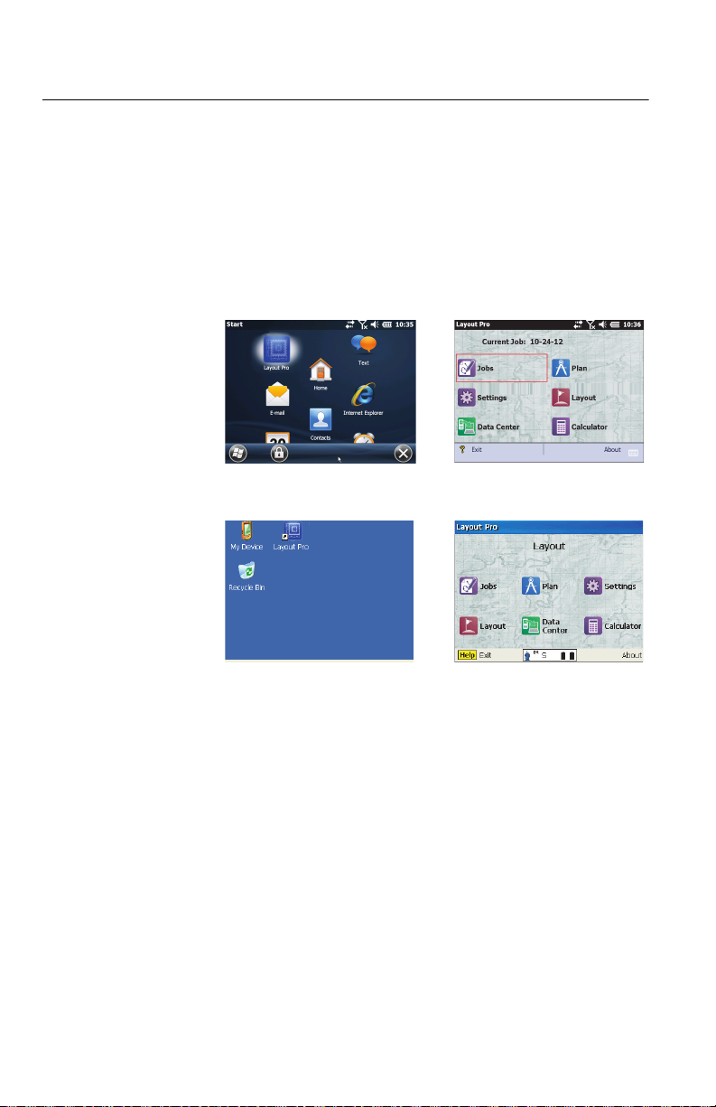
Getting Started
[1] [3]
[2] [4]
Double-tap the Layout Pro icon on the data collector ([1]) or
total station ([2]) desktop.
With a data collector, the main menu ([3]) will appear
instantly.
With the onboard version, you will first have to level the total
station and enter a few parameters (atmospheric, instrument
parameters) before the main menu ([4]) displays.
Note: In this guide, all screenshots showing a blue title bar originate
from the onboard version of Layout Pro (i.e. running on the
instrument used). All screenshots with black title bar are taken from
a data collector connected to a total station.
1
Page 12
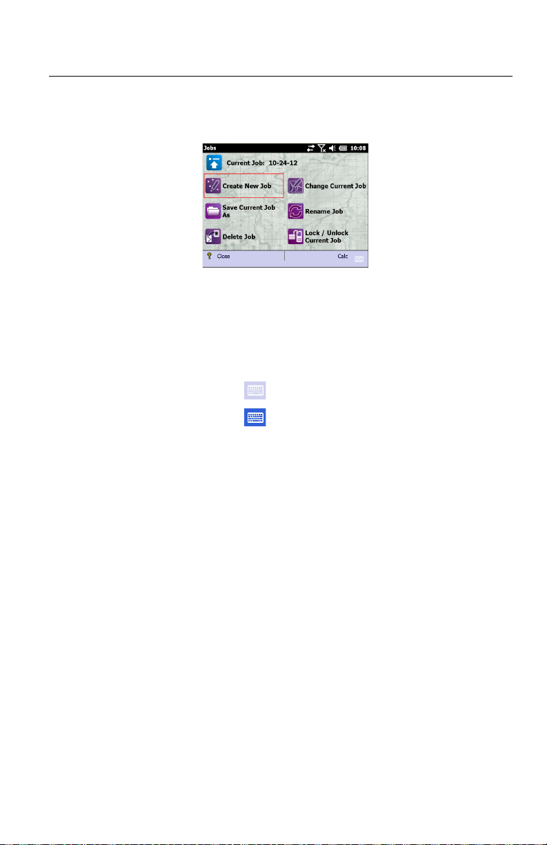
Working With Jobs
Starting a New Job 1. Tap Jobs on the main menu. This opens the Jobs menu.
2. Tap Create New Job.
3. Using the keypad, key in a name for the job. The default
name is the current date. Change it as you prefer.
If you are using a data collector:
– Tap to show the keypad
– Tap to hide it.
4. Tap ok at the bottom of the screen.
5. Tap OK to continue.
2
Page 13
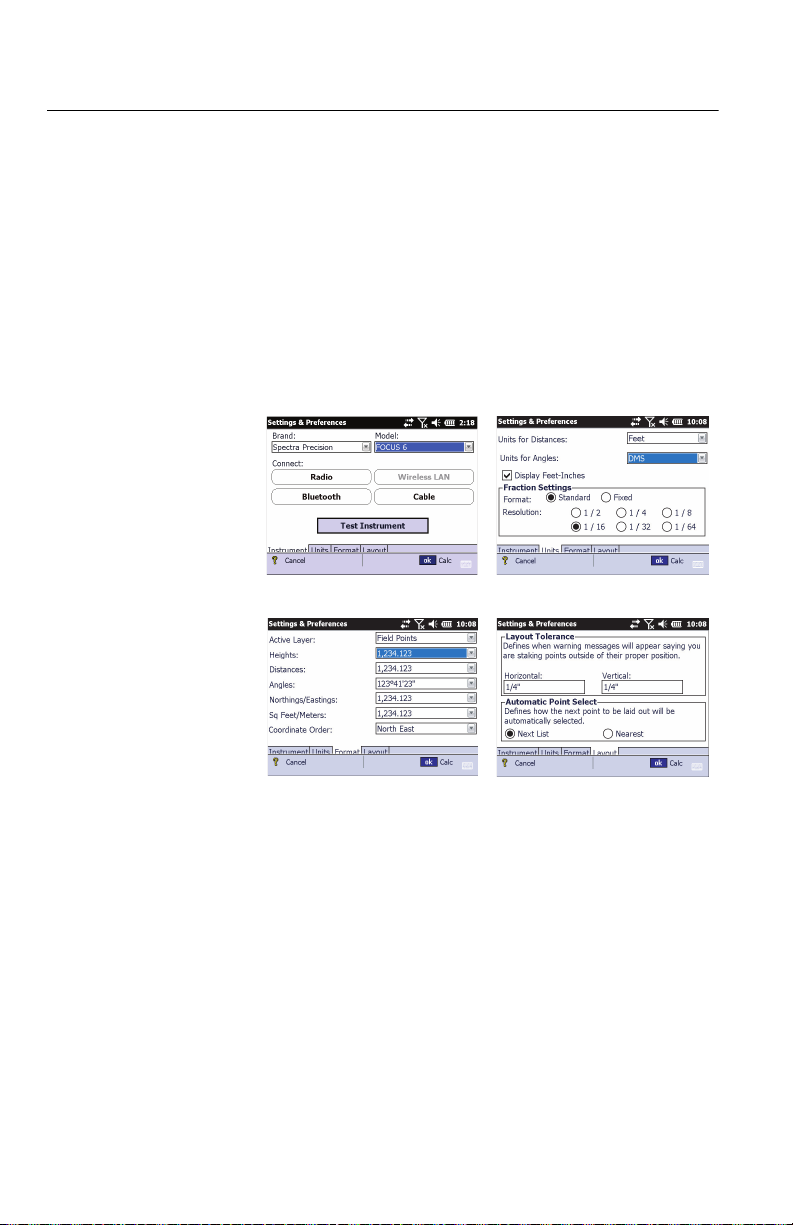
Settings and Preferences
[1] [2]
[3] [4]
From the main menu, tap Settings. The Settings & Preferences
window allows you to set:
• The instrument used ([1]) (with a data collector) or some
instrument-related parameters (atmospheric parameters,
calibration, reflectorless target settings) with an onboard
version.
• The distance units used ([2])
• The format used to display values of distances, angles,
etc. ([3])
• The layout tolerance and automatic point selection ([4])
Simply tap on the next tab to view the next page of options.
Tap ok to close the Settings & Preferences window.
3
Page 14
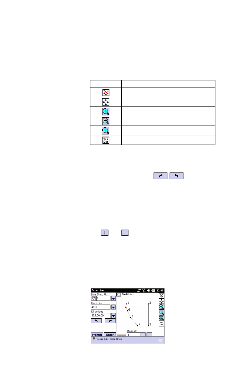
Entering a Plan from a Blueprint
Entering a
Basic Plan
1. From the main menu, tap Plan.
2. Tap Input Plan to begin entering your plan.
The following table shows the tools on the right side of the
window that help you work with the display plan.
Use this tool... to...
Select from plan
Show the whole plan
Zoom in on active point
Zoom out from active point
Zoom to select area
Set display options for labels (point names, etc.)
3. Enter or select a line start point.
4. Enter the length of the new segment.
5. Set the direction that the line is to be placed. To do this:
– Use the rotate buttons to rotate it by a
specified angle.
– Select an angle from the drop-down list.
– Manually enter the angle.
6. Multiple segments of the same length and in the same
direction can automatically be generated. To do this, key
in the number of segments in the Repeat field.
The and icons can also be used to increase or
decrease the number of segments.
7. After your segment, or series of segments, has been
defined, tap Enter on the screen The segment, or series of
segments, then appears on the map.
8. Define the next segments as explained above, until all the
segments have been entered (see example below).
4
Page 15
Adding an Arc
P1
R
α
H
A
to a Plan
B
C
P2
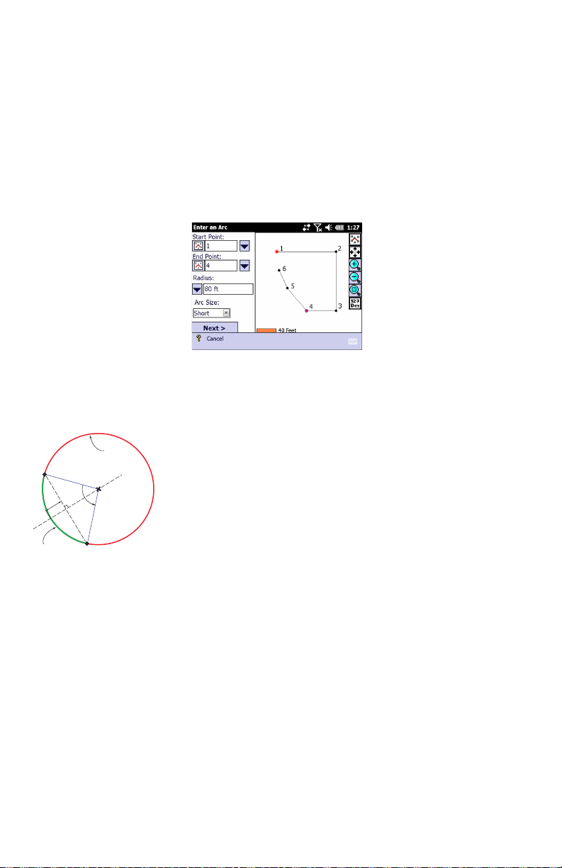
1. Select Enter an Arc from the Tools menu located at the
bottom of the Enter Line window.
2. Choose the start point (P1) and end point (P2) of the arc.
These points can be selected from the plan, or from the
list of points, after selecting the corresponding option
through the nearby scroll-down arrow button. You can also
key in manually their numbers (if known).
The selected points will then appear in red on the plan
(see below).
3. Select which third parameter you will be using to let
Layout Pro build the circle underlying the arc you want to
create (this circle intersects the selected start and end
points). This parameter can be:
– Radius: The radius (R) of the underlying circle (default
option).
– Segment Height: The greatest perpendicular distance
(H) from the chord (P1P2 segment) to the arc.
α
– Center Angle: The angle (
) formed by the start point
(P1), the center point (C) of the underlying circle and
the end point (P2).
– Diameter: The diameter (D=2R) of the underlying circle.
4. Enter the known value for the chosen parameter.
5. Choose whether you wish to define the arc as the short (A)
or long (B) section of the underlying circle (choose Short
or Long).
6. Tap Next. The arc appears in red on the plan.
7. Before entering the arc, you can still define the following:
– Seg. Number: Number of segments of equal length you
want to create along the arc (Default: 1). Creating two
or more segments implies that the corresponding
number of points will be created on the arc.
– Store Center Pt: Enable this option to store the center of
the underlying circle. When enabled, a name is
prompted for this point which you can keep or change.
5
Page 16

– Flip button: Tapping this button provides the other
possible orientation for the arc. Tapping again this
button will bring the arc back to its initial shape.
8. Tap Solve when you agree with the definition of the arc,
which then appears on the plan. See example below.
Remember, you can always step back while creating an
arc (or a line) using the Back button when shown. Once the
arc (or line) has been created, it can be deleted by tapping
Undo at the bottom of the screen.
Creating a Point
Pattern
A point pattern is a group of points placed at known locations
around a central point. The central point has no known
position until you decide what to do with the point pattern.
Later, when you associate (“anchor”) the point pattern to
point P on the plan, this central point will be assigned the
position of point P and the group of points will then appear
around this point P.
To create a point pattern, follow the instructions below:
• Go back to the Plan menu and then tap Edit Point Patterns.
• To define the first point in the point pattern, enter its
coordinates in the X and Y fields in relation to the central
point, which is the origin of the axis system shown.
• Tap Enter to create the point which then appears as a red
dot at the expected location.
Enter a minus sign before the X coordinate if the point
must be located to the left of the vertical axis. Enter a
6
Page 17

minus sign before the Y coordinate if the point must be
located below the horizontal axis (see examples below).
• Repeat the previous two steps until all the points have
been created. If you make a mistake on entering a new
point, tap Undo in the lower bar (the last created point will
be deleted) and resume the point creation step. Note that
Undo can be used to delete the last three entered points.
• After all the points have been created, tap on the Save
Pattern button to save the point pattern as a *.lpp file (the
default name is the current date in mm-dd-yy format).
• Then tap Cancel to quit the Point Pattern editor.
Later on, if you wish to make changes to this point pattern (to
add or delete points):
• Go back to Plan, Edit Point Patterns and use the Load Pattern
button to select, load and edit the corresponding lpp file.
• You can for example delete points from the pattern: First
tap Delete in the lower bar, then select one or more points
on the map, tap the Delete button, and tap OK to confirm
deletion.
• Save the modified point pattern using Save Pattern.
Inserting a Point
Pattern into the
Plan
• Go to Plan and select Input Plan.
• Tap Tools, then Insert Point Pattern.
•In the Select Points field, specify the name of the point
where to anchor the point pattern. The selected point then
appears as a red dot.
• Tap on the Browse button and select the llp file containing
the desired point pattern, then tap ok.
• Optionally, you may rotate the point pattern around the
selected anchor point by a value you enter in the Rotation
field (e.g. 45°).
• Tap on the Next> button. The map shows where the point
pattern will appear on the plan (below left). The group of
points is shown as red dots around the point selected in
the plan.
7
Page 18

• Tap on the Finish button if you agree (below right),
otherwise tap <Back to redo the placement or select
another point pattern.
The points from the point pattern are named as follows:
<Anchor point name> - <order of creation in point pattern>
Example: “2-2” designates the 2nd point in the point pattern anchored to
point 2 in the plan.
NOTE: The same point pattern may be anchored to
different points in the plan, with different rotation values.
Deleting a Point
Pattern
Points belonging to a point pattern may be deleted
individually using the same procedure as the one used to
delete any other “normal” point.
You can also delete a point pattern in one operation, i.e. you
can delete all its points at once.
• Go to Plan and select Input Plan.
• Tap Edit, then Delete > Del. Pts Pattern.
• Tap on to be able to select a point pattern on the map
with the stylus.
• Tap on any point part of the pattern, including the anchor
point (a point part of the pattern will appear in red, the
anchor point in blue).
• Tap ok at the bottom of the screen. Layout Pro will
highlight all the points concerned, including the anchor
point (which however will NOT be deleted as a point).
• Tap on the Delete button if you agree.
8
Page 19
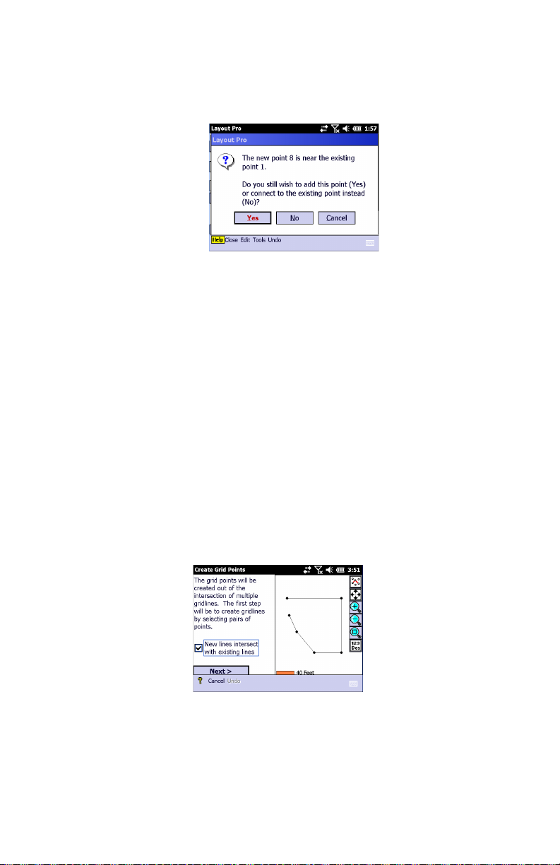
Closure Check As you enter the last point from the blueprint, a dialog box
appears and asks whether you want to add the point or
connect it to an existing point. See example below.
To perform a closure check at any time, select Perform Closure
Check from the Tools menu.
Use the zoom-in tool to see any error which can be caused by
a “bust” in the blueprint dimensions or entering the
dimensions incorrectly.
If a dialog box does not appear when you enter the last point
on your blueprint, your plan does not close or you must select
the Check for Overlapping Points function by selecting Options
from the Tools menu.
Creating Grid
Points
Additional points may be created on the plan by creating new
lines based on existing points. The new points will result from
the intersections of these new lines and possibly also with the
other existing lines.
1. Tap Plan on the main menu.
2. Tap Create Grid Points. Below is an example of what you can
see on the screen.
9
Page 20

3. Set the New lines intersect with existing lines option as
follows:
– Check it on if you want to create points for every
intersection.
– Clear it if you want to create points only at the
intersections of the lines you specify.
4. Tap Next and define the new lines. For each new line,
select the start point and end point directly on the plan.
You are then prompted to name the line. The line and
resulting new points appear in red on the plan.
Create as many lines as necessary. See example below.
5. When the plan shows all the points you would like to add,
tap Store to save all of them.
10
Page 21

Creating Points
from an Imported
DXF File
Introduction
You can create points from a DXF file you import into the open
job. The points will be part of the open job.
After importing a DXF file, the Create Points from DXF function
in the Plan menu is made active. This function allows you to
view a separate map showing the content of the DXF file on
which you can create the points you need, based on the
selections you make and the options you choose (see below).
Once created, these points will also be visible on the plan of
the open job (as well as the content – the “shape”– of the DXF
file in the background).
The points you may create with the Create Points from DXF
function are the following:
• The center point of the arc you select
• The ends of the line you select, and possibly intermediate
points defining equal segments along the line.
Additionally, the points may be offset horizontally and/or
vertically with respect to the line,
• The intersection point of two lines you select
• Any point you pick on a line or an arc.
General Procedure
• Open the job in which to create new points.
• Go to the main menu and tap Data Center.
• Tap Import DXF.
• Select the desired dxf file and tap ok.
• Go back to the main menu and tap Plan.
• Tap Create Points from DXF. The figure below is an example
of what the screen will look like at this stage.
• Tap on one of the buttons (see table below), and then
select the expected object on the map, which is then
highlighted. Note that some of the buttons allow multiple
taps to create multiple points at a time.
11
Page 22

Icon Function
Tap on this button to select an arc on the map. Layout Pro then suggests you create a point at the center point of the selected arc.
Tap on this button to select a line on the map. Layout Pro then suggests you create a point at either end of the line (line nodes).
Additionally, you can create intermediate points on the line between
these two points by selecting the Line Nodes and Interval option
and specifying the distance between intermediate points (in the
Point Interval field).
The points you are about to create can all be offset horizontally from
the selected line using the Horz. Offset field. A positive value will
offset the points to the right of the line, a negative value to the left
(see diagram).
Likewise, the points can be offset vertically using the Vert. Offset
field. A positive value will offset the points upward (above the line), a
negative value downward (under the line).
If you don’t want to offset the points just keep the two offset values
equal to zero.
Tap on this button to select a line or an arc on the map. Layout Pro
suggests you create a point at each end and you divide the line or
arc into equal segments. Segments may be defined by specifying
the length of each segment (Segment Length option), or by specifying the number of segments desired (No. of Segments option).
Tap on this button to select one line, then to select a second line that
intersects with the first one. Layout Pro then suggests you create a
point at the intersection of the two lines.
Lines may be selected directly (Line Segment) or by selecting successively their start and end points (Start/End Points). This choice
can be made by tapping on the down-arrow button (top left).
When a line is selected, its end points turn red making it look like
points will be created there, but they are not. It’s just showing the line
selection.
Tap on this button if you want to delete points. Layout Pro then suggests you select the point or points you wish to delete.
If the area where you tap contains many points close to each other,
Layout Pro will zoom in each time you tap on it until you can see
each point distinctly and you can select one rather than the others.
Tap on this button to create a point on a line or an arc. If you tap on a
line, the point will be created according to the selected criteria: Use
the down-arrow button (top left) to define the criteria (one or more). If
you tap on an arc, the point will be created where you tapped (it can
be anywhere).
If you select an existing point, Layout Pro suggests you change the
name or description of this point.
(Top right) This button allows you to define the elevation of the
point(s) you are about to create. Three options are possible:
• Use DXF elevation
• Enter the elevation for the point(s) being created
• Ignore elevation
12
Page 23
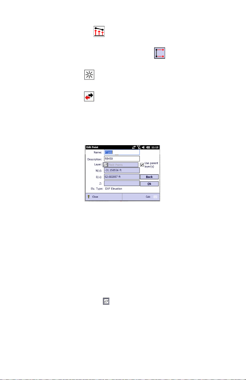
• Tap to define the elevation of your point(s); (see table
above).
If you selected a line through , two additional buttons
can be seen on the screen:
: Allows you to select a line by specifying successively
two points to define the line.
: Changes the orientation of the selected line.
• Tap Next. What happens next depends on which tool you
are using (see table above).
After you have defined the new points on the map, Layout
Pro will ask you to name the point(s). (See example
below).
• Enter a name and a description for the point.
If several points are to be created, enter a name for the
first point (e.g. “PT”). The next points will be named
“PT2”, “PT3”, etc. The description you enter will be the
same for all the points.
If several points are to be created, the N,E,Z coordinates
are not shown.
• Define the layer for the point(s): By default all the points
are assigned the parent layer defined in the imported DXF
file.
If you wish to assign a different layer:
– Clear the Use parent layer(s) box
– Tap
– Select the desired layer name and tap ok.
• Tap Ok to complete the point creation process. This takes
you back to the initial screen from which you can create
new points.
13
Page 24

Making Computations from your Entered Plan
1. Tap Plan on the main menu.
2. Tap Compute with Plan on the submenu.
3. Tap in the lower-right corner of the screen. This opens
up a menu from which you can perform various
computations:
4. Select Compute Area to compute the area and perimeter of
a group of points:
14
5. Select Compute Distance to compute the distance between
two points:
Page 25

6. Select Compute Angle to compute the angle between any
three points:
7. Select Compute Down & Out to compute a point’s down and
out distance from a line that you specify:
The blue line is the reference line. The red section that is
overlaid on the blue line is the “down” portion. The red
perpendicular line is the “out” portion.
15
Page 26

Setting Up a Connected Total Station
Before using a total station to perform a stakeout or survey,
you must set up your total station (in the location you want to
shoot from), level it, and turn it on.
If you are using the onboard version of Layout Pro, nothing
else needs to be done.
If you are running Layout Pro on a data collector, connect the
data collector to the total station using a serial cable or
Bluetooth.
Tolerance &
Connection
Settings
Recommended
Settings for
Supported Total
Stations
To set the parameters on the Layout Pro software:
1. From the main menu, tap Settings.
2. From the Layout tab, enter the desired layout tolerance.
3. From the Instrument tab (the first tab), select the brand
and model of the total station from the Brand list.
4. Set the parameters on the total station from the settings
recommended in the section below.
FOCUS 6, Nikon 300 & 500, Nivo M and DTM/NPL-322
(Tap the menu key on the total station, select Settings, and
select Comm.)
• Ext. Comm (set to NIKON)
• Baud (4800 or match to Layout Pro)
• Length (set to 8)
• Parity (set to none or match Layout Pro)
• Stop Bit (set to 1)
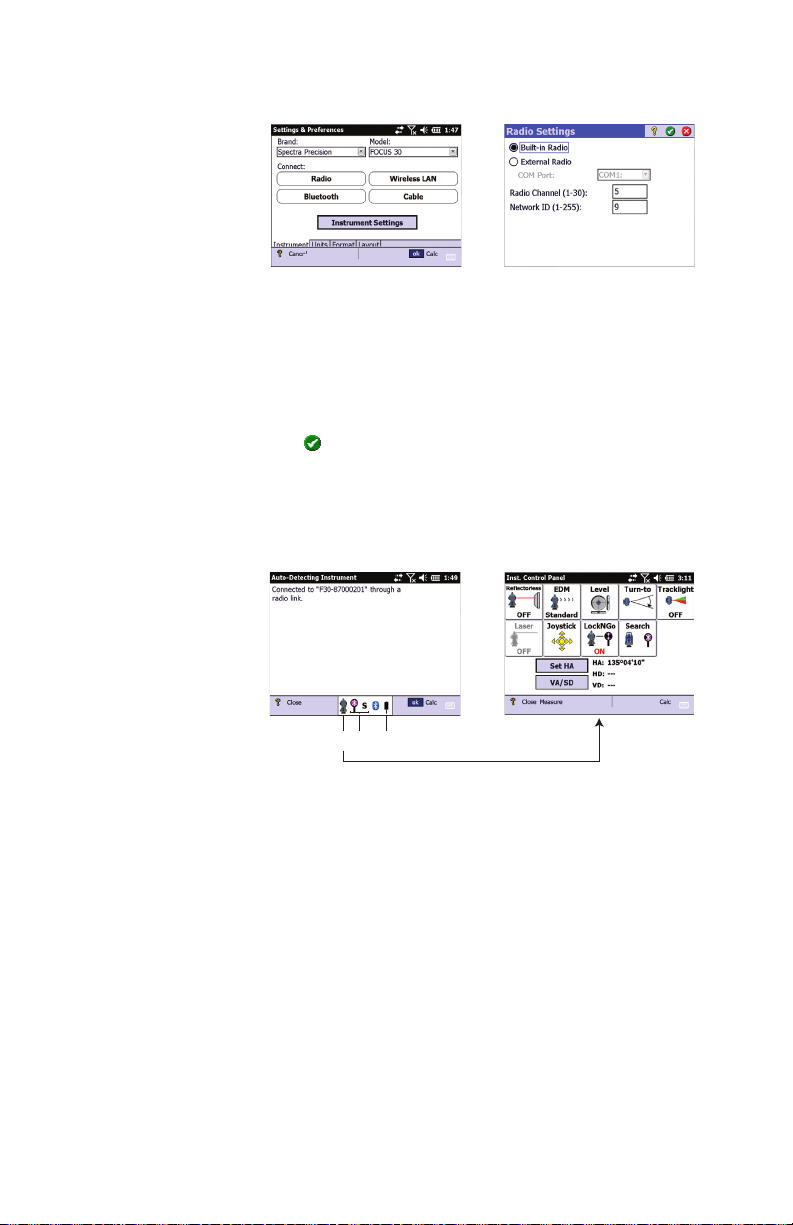
Spectra Precision FOCUS 30 Robotic Total Station
You will typically use a Ranger 3 data collector for controlling
a FOCUS 30 Robotic total station.
1. Turn on both the data collector and the FOCUS 30.
Launch Layout Pro on the data collector.
2. From the main menu, tap Settings.
3. On the Instrument tab, select “Spectra Precision” from the
Brand list, and “FOCUS 30” from the Model list (see
screen [1] below).
4. Tap on the Radio button, This opens the Radio Settings
screen (screen [2] below).
16
Page 27
[1] [2]
[3] [4]
45 6
5. Select Built-in Radio and then enter the radio channel
(Radio Channel) and network ID (Network ID) required to
communicate with the FOCUS 30.
The radio channel and network ID you should type in are
those you can read on the FOCUS 30 Face 2 control unit
(e.g. Radio Channel=5 and Network ID=9).
6. Tap to enter these two parameters. Wait until the data
collector detects the FOCUS 30 and establishes the radio
connection. The data collector screen then looks like
screen [3] below.
From now on, as long as the robotic total station remains
connected, the status bar will provide access to the
following information taken from the robotic total station:
– 4: Access to Instrument Control Panel consisting of
nine different buttons (Reflectorless ON/OFF, EDM
Standard/Tracking, Level Bubble, Turn-To, Tracklight
ON/OFF, Laser ON/OFF, Joystick, LockNGo ON/OFF,
Search), HA setting and a Measure function (see screen
[4] above).
– 5: Target type selection and search angle range
settings. A new target search will be automatically
started when quitting this screen by tapping OK.
– 6: Remaining power in the FOCUS 30 battery.
17
Page 28

7. Tap ok to return to the Setting & Preferences screen. From
this screen, you can now use the Instrument Settings
button to access other instrument settings such as
instrument name (on General tab), EDM, Lights, Search
and Collimation, EDM, Lights
8. Tap ok again to return to the Home screen.
18
Page 29
Station Setup
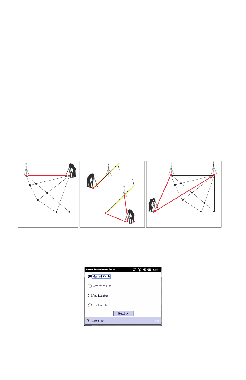
If you choose to set up the total station over a marked point
from the plan (Marked Points choice, diagram [1] below), you
will need to shoot one other point.
You may set up the total station on any location either on or
off a reference line (Reference Line choice, see diagram [2]
below). This method can only be used with no plan entered.
If you choose to set up the total station at a random location
(Any Location choice, diagram [3] below), you will need to
shoot at least two marked points from the plan for angle and
distance measurements, or at least three points if only angles
are to be measured. In either case, you can decide to shoot
more points for better control.
If you choose Use Last Setup, the total station will use the
coordinate system you determined when last setting it up (i.e.
according to one of the three methods described above).
PT1
Origin
Origin
Reference
Line
PT1
[3][2][1]
The four possible station setup procedures are described
below.
1. Tap Instrument Setup from the Layout menu.
2. Choose how to set the instrument:
3. If you choose Marked Points (see also diagram below):
PT2
19
Page 30

• Tap Next.
[1] [2]
[3] [4]
• Select the point from the plan where to set up the
instrument ([1]). Set up the instrument at this
location.
• Tell Layout Pro whether you want to measure elevation
(Yes/No) then tap Next. If you are setting up on a known
point and you want to measure elevation, first enter the
instrument height, then tap Next.
• Select the reference point from the plan ([2]). Have a
target placed over this point.
• Check that everything is ready for a shot ([3]), aim the
instrument at the target and then tap Shoot.
• After Layout Pro has reported a valid measurement
([4]), tap Finish. Station setup is now complete.
20
NOTE: If there is only one point stored in the plan,
then Layout Pro will assume this point (with known
coordinates) is occupied by the instrument, and will
prompt you, from this point, to shoot a reference point
with unknown coordinates.
Page 31
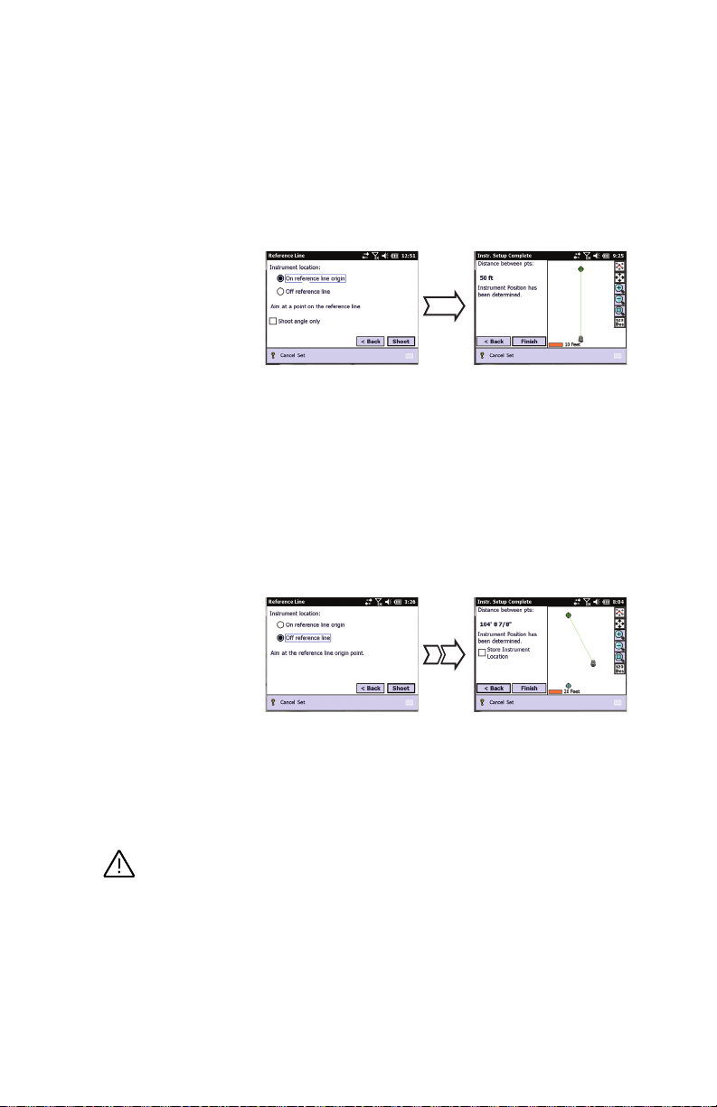
4. If you choose Reference Line, tap Next. Two options are
[5] [6]
[7] [8]
possible:
• Either you set up the instrument on the origin of the
reference line. (The origin will have been marked on
the job site.) You just have to shoot another point of
your choice, also located somewhere on the line (see
[5] and [6] below). You may measure elevations or not
(see below). Tap Finish when it’s done.
As a result, two points are created:
point “1” (origin): N(y)= E(x)= 0
point “2”: N(y)= non-zero distance value, and E (x)= 0
• Or you set up the instrument somewhere off the
reference line and you shoot two points located on the
line (see [7] and [8] below). The first of these points
MUST be the origin of the line, the other one may be
located anywhere along the line. You may measure
elevations or not (see below). Tap Finish when it’s done.
As in the first method, two points are created if you do
not save the instrument location:
point “1” (origin): N(y)= E(x)= 0
point “2”: N(y): non-zero distance value, and E (x)= 0
It is strongly advised to store the instrument location
as well (by enabling the Store Instrument Location option
prompted on the screen). The resulting point will be
named “point 1”. You may add a description for the
point. In that case, the other two points will be named
respectively “2” for the origin (1st point shot), and “3”
for the 2nd point shot.
21
Page 32

Setting the Elevation of the Instrument Location (with
instrument located either on or off the line): When
selecting the Reference Line method in the Instrument
Setup menu, you are first prompted to measure
elevation. If you choose “No”, the procedure will be as
described above and all measured points will be 2D
points, including the instrument point and the marked
points.
If you choose “Yes”, you will additionally need to enter
the instrument height before going any further ([9]),
and then the rod height when you specify the
instrument location (on or off the line) ([10]).
Just before completing the instrument setup, you will
be able to set the elevation of the instrument location
to be that of a nearby benchmark point. To do this, tap
on the Use BM Elev button ([11]), enter the known
elevation for the benchmark point ([12]), then place a
prism on the benchmark and shoot that point from the
instrument location ([13]).
Layout Pro will calculate and display the elevation for
the instrument location ([14]). You will confirm this
elevation by tapping Finish twice.
[9] [10]
22
[11] [12]
[13] [14]
Page 33

5. If you choose Any Location (see also diagram below):
[15] [16]
[17] [18]
[19]
• Tap Next.
• Tell Layout Pro whether you want to measure elevation
(Yes/No). If you want to do so, enter the instrument
height (as measured from the ground). Then tap Next.
• Set up the instrument at any convenient location from
which you have a good view of the two reference points.
• Select the first reference point from the plan ([15]).
Have a target placed over this point. Aim the
instrument at this point and shoot it ([16])
• Repeat the first step for the second reference point
used ([17] and [18]). You then get screen [19] on
which the instrument position is reported to have been
determined. Ensure that the calculated position of the
instrument makes sense compared to the plan.
• Tap Finish to complete station setup. If you want to
store the point where the instrument is located, first
enable the Store Instrument Location option, tap Next,
name the point and tap Finish.
6. If you choose Use Last Setup, and you tap Next, Layout Pro
will ask you to aim at the reference point to check the
setup you used previously. You may additionally shoot the
reference point to check the angle.
23
Page 34

Performing Stakeout
Note: Unless otherwise specified, all the instructions given in this
section apply to both mechanical and robotic stations. Whenever
found useful, two screenshots are shown side by side, one for
mechanical total stations (on the left), the other for robotic total
stations (on the right). When a single screenshot is shown, that
means there is no significant difference between mechanical and
robotic. In that case, the screenshot is shown for mechanical only.
Stakeout Using an
Entered Plan
1. When everything is set up correctly (see Station Setup on
page 19), tap Points from the Layout menu.
2. From the Layout Pro display, select the point you want to
stake (then shown on the map as a red dot inside a green
circle). The horizontal angle and horizontal distance to
that point from the total station are displayed.
3. Tap Next. Layout Pro calculates and displays the value and
direction of the angle – measured from the last shot – the
instrument should be rotated to be aligned with the stake
point.
4. With a mechanical total station, rotate the instrument in
order to zero this angle. When done, the instrument is in
line with the point to be staked. Get the rod holder on the
same line and tap Shoot to take a measurement. The angle
value is shown in bold red on the screen, with right/left
direction arrow (see example below left).
With a robotic total station, enable the LockNGo function
and run a target search to lock the instrument onto the
target. The instrument starts updating distances
continuously (the EDM automatically changes to Tracking
mode) and shows map guidance to the point location.
24
Page 35

The instrument is always shown at the top of the screen
Mechanical Robotic
Mechanical Robotic
and the green line connecting the instrument to the rod
location is always vertical. A blue line with arrow point
connecting the rod location to the stake point gives the
direction to that point (see example below right). You can
also use the tracklight to guide you.
5. With a mechanical station, the rod being now roughly in
line, the rod holder should normally be asked to move
forward or back, according to the instructions provided by
Layout Pro. After the rodman has made a significant
move, aim your instrument at the rod and tap Shoot again.
The Layout Pro display provides new indications, left or
right and forward or back, still in the perspective of the
total station operator.
With a robotic total station, move closer to the point
following the instructions on the data collector screen.
For both types of total stations, when the rod gets closer
to the stake point, the Layout Pro screen enters a new
guidance mode: the rodman location is represented by a
green circle and black reticle, the stake point location is
represented by a red circle and spot (see screens below).
6. With a mechanical station, continue to guide the rodman
closer to the stake position and re-shoot.
25
Page 36

With a robotic total station, you can use the Shoot button
Mechanical Robotic
to take a measurement (the instrument will switch to
whatever EDM mode is set in the instrument settings for
this measurement, and then will switch back to Tracking
EDM). This will update the “text” guidance information on
the screen but will freeze it until the Shoot button is used
again. The graphic guidance will, however, continue to be
updated as you move to the stake point, based on the
measurements made by the instrument.
For both types of total stations, you can re-shoot as many
times as necessary until the rod is within an acceptable
range of the correct position. Tap Stk> when an acceptable
position is established. (Tapping Store would allow you to
store any measurement made for a point of interest
located somewhere around the stake point.)
7. Tap Store & Next Pt to store the position of the rod and to
NOTE 1: In robotic, you can also use quite the same
procedure as with a mechanical total station. Tap the Aim
button at the beginning of the process (rather than the Next
button) to bring the instrument in line with the stake point.
Move the rod to be in line as well. You can then use the track
lights to keep in line and move to the point location. Also,
when you get in line with the instrument and the stake point,
you can alternatively enable the Auto-Track function to make
it easier to get to the point location.
NOTE 2: Do not confuse the “Auto-Track” function (LockNGo
on FOCUS 30), i.e. the capability of an optical instrument to
continuously track the rod, and the “Tracking” EDM mode,
which is an operating mode through which an EDM performs
continuous distance measurements.
26
go back to the Define Stake Point screen from which you can
select the next point you want to stake.
Page 37

Stakeout Using a
Reference Line
1. When everything is set up correctly (see Station Setup on
page 19), tap Line from the Layout menu.
2. Select two points for the reference line on the Layout Pro
display. (You may also select an existing line directly to be
used as the reference line.)
3. Tap Next. Layout Pro calculates the distance between the
two points you selected. The Flip button can be used to
reverse the definition of the reference line (AB or BA)
4. Tap Next. You can choose between Stake Out Points and
Show Position (see screen below).
• If you choose Stake Out Points and tap Next, a screen
appears that explains the down and out method of
measuring stake points (see screen below).
27
Page 38

Key in the down and out positions for the point you
want to stake.Tap Next. Layout Pro then computes the
coordinates of the stake point.
With a mechanical total station, rotate the instrument
in order to zero the angle to the stake point. When
done, the instrument is on line with the point to be
staked. Get the rod holder on the same line and tap
Shoot to take a measurement. The angle value is shown
in bold red on the screen, with right/left direction arrow
(see example below left).
With a robotic total station, enable the LockNGo
function and run a target search to lock the instrument
onto the target. The instrument starts updating
distances continuously (the EDM automatically
changes to Tracking mode) and shows map guidance to
the point location.
For both types of total stations, complete the
procedure as you would for a stake point selected from
the entered plan.
• If you choose Show Position, no entries are made.
Simply take a shot at the rod and the position is shown
in relation to the reference line. See examples below.
Mechanical Robotic
28
Page 39

Stakeout Using a
P1
P2
B
A
c
R
P2
P1
P1
P3
P2
[1]
[2]
[3]
[4]
Reference Arc
1. When everything is set up correctly (see Station Setup on
page 19), tap Arc from the Layout menu.
2. Define the reference arc or select an existing one from the
plan, using one of the four options below.
• Two points on the arc & radius (see diagram [1]): Select
the start (P1) and end (P1) points from the plan, key
in the radius (R) and choose the short (A) or long (B)
section.
• Three points on the arc (see diagram [2]): Select the start
(P1), arc (P2) and end (P3) points from the plan.
• Center point & a point on the arc (see diagram [3]): Select
the center point (P1) and arc point (P2) from the plan.
This option defines a full circle. P2 is the start of the
arc and the direction of the arc is clockwise.
• Select existing arc (see diagram [4]): Select an existing
arc from the plan. Both the arc and the points defining
the arc will be selected together.
Tap Next after making a choice and follow the instructions
until the reference arc definition is complete (see example
below).
29
Page 40

3. Tap Next. You can choose between Stake Out Points and
Show Position (see screen below).
• If you choose Stake Out Points and tap Next, a screen
appears that explains the down and out method of
measuring stake points (see screen below).
30
Key in the down and out positions for the point you
want to stake.Tap Next. Layout Pro then computes the
coordinates of the stake point.
With a mechanical total station, rotate the instrument
in order to zero the angle to the stake point. When
done, the instrument is on line with the point to be
staked. Get the rod holder on the same line and tap
Shoot to take a measurement. The angle value is shown
in bold red on the screen, with right/left direction arrow
(see example below left).
With a robotic total station, enable the LockNGo
function and run a target search to lock the instrument
onto the target. The instrument starts updating
distances continuously (the EDM automatically
changes to Tracking mode) and shows map guidance to
the point location.
Page 41

For both types of total stations, complete the
procedure as you would for a stake point selected from
the entered plan.
• If you choose Show Position, no entries are made.
Simply take a shot at the rod and the position is shown
in relation to the reference arc. See example below.
Mechanical Robotic
31
Page 42
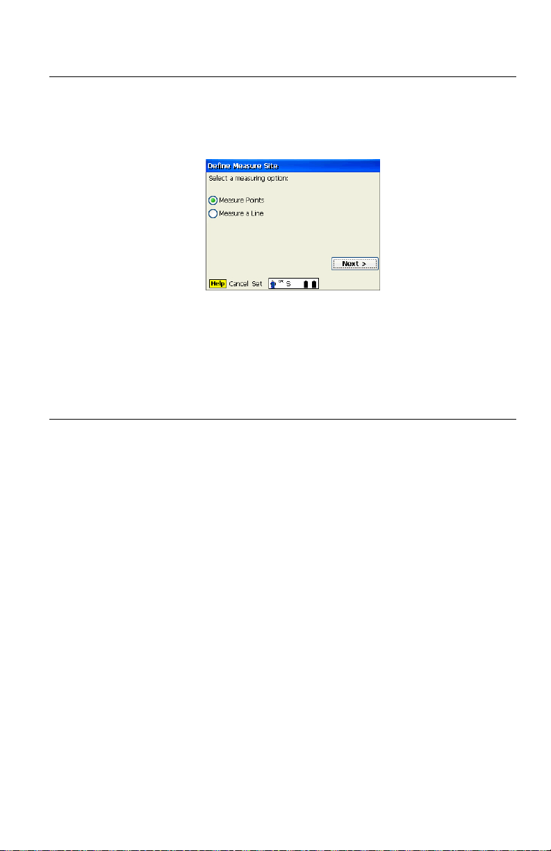
Measuring Features
1. When everything is set up correctly (see Station Setup on
page 19), tap Measure Features from the Layout menu. You
may choose to measure either points or a line.
2. Enter a description (if desired) for the line or point being
measured. Tap Shoot. The feature is measured and the
result automatically stored.
3. Repeat as necessary until all points have been measured.
Using Layout Pro Field Software to Import/Export Data
Tap Data Center on the main menu. From the submenu, you
can do the following:
• Import DXF: Layout Pro creates a background map from the
imported DXF data.
• Export DXF: Layout Pro exports the open job to a DXF file.
• Import Points: Layout Pro can import an ASCII file
containing point coordinates. The points are created in a
new job file and that file is automatically open for use.
• Export Points: Layout Pro exports all the points from the
open job to a text file. You can choose the separator (a
comma or a tab).
• Export Layout Data: For each staked point, Layout Pro
provides the coordinates of the design point and the
corresponding as-staked point, as well as the horizontal
and vertical deviations between the two points.
• Export Deviation Data: Layout Pro creates a text file listing
all the staked points with their horizontal and vertical
deviations compared to the respective design points.
• Out of Tolerance Report: Layout Pro provides a report of all
the points that are staked out of tolerance.
32
Page 43

Page 44

Layout Pro Field Software
Quick Start Guide
SPECTRA PRECISION
Survey Support:
Email: support@spectraprecision.com
US & Canada: +1 888 477 7516
Latin America: +1 720 587 4700
Europe, Middle East and Africa: +49 7112 2954 463
Australia: +61 7 3188 6001
New Zealand:
Singapore: +65 3158 1421
China: 10 800 130 1559
+64 4 831 9410
Contact Information:
AMERICAS
Spectra Precision Division
10368 Westmoor Drive
Westminster, CO 80021, USA
www.spectraprecision.com
©2012-2014 Trimble Navigation Limited. All rights reserved. Spectra Precision is a Division of Trimble Navigation Limited. Spectra Precision and the
Spectra Precision logo are trademarks of Trimble Navigation Limited or its subsidiaries. April 2014
EUROPE, MIDDLE EAST AND AFRICA
Spectra Precision Division
Rue Thomas Edison
ZAC de la Fleuriaye - CS 60433
44474 Carquefou (Nantes), France
ASIA-PACIFIC
Spectra Precision Division
80 Marine Parade Road
#22-06, Parkway Parade
Singapore 449269, Singapore
 Loading...