

Page 1

May 2017
GL6X2N
Hands-On training
Page 2
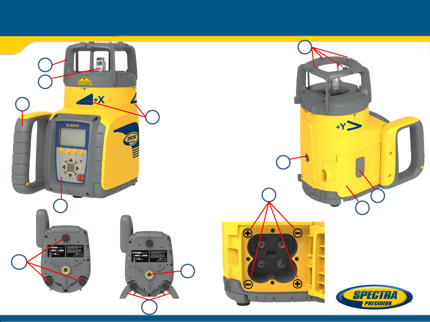
a - Keypad/LCD-Display
b - Handle
c - Rotor
d - Roll Cage
e - Axes Alignment Marks
f - Sighting Guides/Scope Mounts
g - Battery door
h - Rubber Cover/Recharge Jack
i - 5/8” x 11 Tripod Mounts
j - Rubber Feet
k -Turnable Legs
l - Plus and Minus Battery
Diagrams
GL612N/622N Components
a
b
c
e
d
f
i
g
h
j
k
i
l
Page 3

Powering the GL612N/GL622N
1 – GL is shipped with a rechargeable NiMH
battery pack (Q104667).
2 – The charger (Q104781) can be used as a
power supply when used Indoors
3 – The rechargeable battery pack can be
charged inside as well as outside of the
unit
4 – Alkaline batteries can be used as a backup
5 – An optional external power cable
(Q104802) is available too
6 – Plus and minus symbols indicate
how to put the alkalines into the
battery compartment
Page 4

Powering the RC602N
1. Open the battery door using a coin or similar pry
device to release the battery door tab on the RC602N.
RC602N will be shipped with alkaline batteries
Rechargeable batteries can be used optional but need
to be charged externally
2. Insert two AA batteries noting the plus (+) and minus (-)
diagrams inside the battery housing.
3. Close the battery door. Push down until it “clicks”
into the locked position.
Page 5

Battery status laser Battery Status Remote Control
Mask selection Radio Connectivity
Rotation speed HI alert
Standard Display
Button 1: MENU
Button 2: Grade Entering Mode
Button 3: Manual mode
Button 4: Rotation/Scan
Button 5, 8: up/down arrow buttons
Button 6, 7: left/right arrow buttons
Button 9: ON/OFF button
1 second to turn on the unit;
2 seconds to turn off the unit.
Leveling/Standby – LED (green/red)
Page 6

Depending on the setup (horizontal) and if a grade value has been
dialed in, the unit starts the temperature/reference check while the
thermometer symbol is flashing.
Don’t start a menu function before the reference check has been
finished.
When the temperature/reference check has been finished, the standard
display appears and the bubble symbols flash until self-leveling has
been completed.
If the self-leveling can’t be finished based on the selected sensitivity, an
error message appears
Turning On/Off the Laser
Page 7

X-Y- grade entering: Digit Select mode (Default)
button 2: Grade Entering Mode.
button 1 quick set to 0%
button 2 change the sign of the grade value
Press and release button 5 or 8 (down or up) to move the cursor to the X- or Y-axis.
Pressing and releasing button 6 or 7 (right or left) moves the cursor to the right/left.
Use button 1 or 2 (Plus or Minus) to set the desired digit.
button 3 return to the standard display
The laser will self-level to the required grade position after confirming the grade change with button 4.
Note: The bubble symbols at the laser’s LCD will flash until the laser has been self-leveled to the requested
grade position.
Standard Features
Page 8

X-Y-grade entering
Step and Go mode
Quickly press and release button 2 starts the grade entering mode.
Both grade values will be shown.
Press/release button 1 grade reverse Y
Press/release button 2 grade reverse X
Press/release button 3 return to the standard display.
Quickly press and release button 4 to confirm the selected grade
value and return to the standard display
Press and hold button 6 or 7 (left/right) to change X- axis grade value
after the comma; press and hold buttons 6 + 7 simultaneously starts X-axis quick change mode
where the grade value in front of the comma will be set to 0% and then starts changing in 1%
increments.
Press and hold button 5 or 8 (up/down) for changing Y -axis grade value; press and hold buttons 5 +
8 simultaneously starts Y - axis quick change mode where the grade value in front of the comma will
be set to 0% and then starts changing in 1% increments
Note: When the grade value for either axis reaches its highest amount, the grade value switches to the
lowest value for that axis. For example, the value switches from +25% to -25%.
The laser will self-level to the required grade position after confirming the grade change with button 4.
Note: The bubble symbols at the laser’s LCD will flash until the laser has been
self-leveled to the requested grade position.
Standard Display
Standard Features
Page 9

Using the Rotation mode
Repeatedly pressing the button 4 toggles through 300, 600, 750 rpm regardless if the unit is in automatic or
manual mode.
Manual mode
Pressing and releasing button 3 at the Standard Display activates/deactivates the manual mode
regardless if set up horizontal or vertical.
Manual mode is indicated by horizontal lines next to the axes symbols. An additional bubble helps to adjust
the laser on the cross axis when set up vertical.
In Manual mode (horizontal), the Y-axis can be sloped by pressing the Up-(5) and Down-(8)- Arrow
buttons on the laser‘s keypad or the remote control. Additionally, the X-axis can be sloped by pressing
the Left-(6) and Right-(7) Arrow-buttons on the laser or remote control.
In vertical mode, the up and down arrow buttons adjust the Z-axis slope, and the left and right arrow
buttons align the laser beam to the right/left side.
To resume automatic self-leveling mode, press the manual button 3 again.
Standard Features
Page 10

Menu Functions (Radio controlled)
Press and release button 1 at the Standard Display to enter the MENU.
The menu offers always only the features which can be selected depending on the setup (horizontal or vertical).
The selected icon will be highlighted. A down arrow at the the right site indicates that the user can scroll down
through the menu using the button 8 (down arrow).
Note: As soon as the menu has been opened, button 2 (question mark) can be used to open a help text which
explains the selected function more in detail.
After going to the next menu row, a up/down arrow at the the right site indicates that the user can scroll
up/down through the menu rows (4 different screens) using the buttons 5/8 (up/down arrows).
Pressing and releasing button 3 changes the unit always back to the standard or previous display.
Press and release the buttons 6/7 until the desired icon at the selected menu row is highlighted.
Press and release button 4 to open the submenu OR start the selected function.
Menu functions when set up horizontal (GL622N)
Menu functions when set up vertical
Special MENU Features
PlaneLok
Grade
Match
Axis Align Mask Mode Standby
Reference
Check
Settings Info Service
PlaneLok Mask Mode Standby Line Scan Settings Info Service
Page 11

The PlaneLok mode can be activated in horizontal and vertical automatic and
manual mode. In PlaneLok mode when set up horizontal, the beam will be
locked to a fixed elevation point (up to 150 m (490 ft) located on one
axis at each side of the laser. For keeping vertical alignments fixed to a
direction point, PlaneLok can be used in both directions on the X-axis.
1. Set up the laser over the reference point.
2. Attach the HL760 receiver to a grade rod. Place the receiver at the second point and adjust it to the
On-grade position. The receiver should be permanently mounted at this location and at the desired
elevation.
3. Use the sighting guides on the top of the laser to align the laser to the receiver. Turn the laser on the
tripod until it is roughly aligned to the receiver’s position (the alignment range on both axes is +/-40).
4. Press and release the MENU button at the Standard Display and select PlaneLok.
5a. When set up horizontally, press and release button 4 to open the PlaneLok submenu; select the
desired PlaneLok axis then press button 4 to start PlaneLok.
Note: The laser starts to search for the receiver. A flashing Receiver and
Lock symbol appears at the selected axis and becomes solid when
PlaneLok has been completed.
Horizontal setup
Vertical setup
Automatic PlaneLok mode
(X only GL622N)
Page 12

5b. When set up vertically, press and release button 4 to open the PlaneLok submenu; select the
desired PlaneLok axis then press button 4 to start PlaneLok.
(Y only with GL622N)
Note: When used in vertical mode, the receiver has to be placed with the photocell on the bottom side.
The HL760 display shows a flashing –PL– during the time the laser is searching and adjusting the beam to the
on-grade position.
When PlaneLok is complete, –PL– stops flashing at the HL760 display.
Note: The laser continues to servo to the receiver’s signals.
6. Exiting of PlaneLok can be done by pressing button 3 (ESC).
Note: If the setup will be disturbed for a minute (beam will be blocked),
an Alert comes up. After deleting the error message with button 4 PlaneLok needs to be started again.
It’s recommended to use the batter board adapter M402 for setting up the GL6X2N and the 105516 vertical
adapter for setting up the HL760.
Automatic PlaneLok mode
Page 13

Steep Slope using PlaneLok
Set up the GL6X2N at the bottom part of the steep slope
area using the slope bracket (M401 laser tilting base).
Check the laser beam elevation and place the receiver at the
desired hub.
Change the GL into manual mode and tilt the unit to the
approx. steep slope position until the receiver on top starts to
catch the beam.
Page 14

10/16/2017 14
Steep Slope using PlaneLok
Select PlaneLok at the menu and start automatic PlaneLok by pressing button 4.
The transmitter starts searching for the receiver HL760 and locks the beam at the on-grade
position.
Page 15

The Grade Match mode can be activated in horizontal automatic mode.
In Grade Match mode, the laser can be used to measure the existing grade value between two known
elevation points (up to 150 m (490 ft) located on one axis at each side of the laser
1. Set up the laser over the reference point.
2. Attach the HL760 receiver to a grade rod. Check the laser’s elevation next to
the laser then position the receiver at the second point WITHOUT changing the
receiver’s elevation on the rod.
3. Use the sighting guides on the top of the laser to align the laser to the receiver.
Turn the laser on the tripod until it is roughly aligned to the receiver’s position
(the alignment range on both axes is +/-40°).
4. Press and release the MENU button at the Standard Display and select Grade Match.
5. Select the desired Grade Match axis then press button 4 to start Grade Match.
Note: The laser starts to search for the receiver. A flashingReceiver an angle symbol
appears at the selected axis and disappears when Grade Match has been completed.
While the laser is searching and adjusting the beam to the on-grade position,
the HL760 display shows a flashing –GM–. When Grade Match has been completed,
the HL760 goes back to the standard elevation display. The remote control as well as the laser
will display the final measured grade value.
Note: If Grade match can’t be completed by checking the limits, the laser comes with an
Error message (Grade Match has Failed) which can be deleted with button 4 (OK).
Automatic Grade Match mode
(X only GL622N)
Page 16

Automatic Axis Alignment mode adjusts automatically the direction
the grade axis is pointing to the receiver’s location by an electronically
simulation of rotating the unit on its base to match the hub.
Using Axis Alignment, the laser axes can be aligned to one
direction hub (up to 150 m (490 ft) located on one axis at each
side of the laser.
1. Set up the laser over the reference point.
2. Place the grade rod with the attached HL760 receiver at the desired direction hub.
3. Use the sighting guides on the top of the laser to align the laser to the receiver.
Turn the laser on the tripod until it is roughly aligned to the receiver’s position.
(the alignment range on both axes is +/-40°).
4. Press and release the MENU button at the Standard Display and select Axis Align.
5. Adjust the receiver into the beam before starting the automatic Axis Alignment to reduce the
time needed for finishing the alignment.
5. Select the desired axis then press button 4 to start Axis Align.
Note: The laser starts to search for the receiver while -AA- is flashing at the HL760 LCD.
Note: A flashing Alignment symbol appears at the selected axis, becomes
solid when Axis Alignment has been completed and then disappers while
the flashing bubbles come back. A short line on top of Y and X
confirms an Axis Alignment has been completed.
Automatic Axis Alignment mode (only GL622N)
Page 17

Mask mode
Select the Mask icon and press and release button 4 to open the Mask setting menu.
Depending on which side or corner the beam should be turned off, the required sector can
be selected.
Press and release the buttons 5 to 8 for moving a short flashing line around the mask
mode symbol.
For selecting the sector where the bar is flashing, press and release button 1 (SET).
After setting the first sector, button 1 changes to show CLR which offeres the capability
of deleting the selected mask sector again. Use button 5 to 8 to move the flashing bar
to other required areas and repeat the setting process.
When all areas have been set, press button 4 to store the mask sector selection until the
unit will be turned off.
Note: The unit always powers up with the mask mode deactivated (default).
Activating/Deactivating Standby mode
Press and release the MENU button at the Standard Display and select Standby.
Pressing and releasing button 4 activates the Standby mode.
The self-leveling will be stopped and the beam will be turned off while the HI alert
is still active.
The display shows the standby symbol and the Level/Standby LED flashes red every 5
seconds. To deactivate Standby mode and restore full operation of the laser, press
and release button 4.
Mask Mode / Standby mode
Page 18

Temp Reference Check / Settings
Start Reference Check
When working during temperature changes and over long distances the product requires
a frequent reference check to maintain accuracy. The transmitter will do reference check
on a regular basis. When carrying out work where accuracy is paramount it is advised to
manually prompt a reference check.
Press and release the MENU button at the Standard display and select Reference Check.
Button 4 starts the reference check considering the current temperature inside the
housing. While the procedure the rotation will be stopped.
Note: A grade value has to be entered before the unit starts the reference check.
Setting Menu
Press and release the MENU button at the Standard Display and select Settings.
Press and release button 4 to open the Setting Menu; select the desired function then
press button 4 to open the selected submenu function OR start the selected function.
Please see the Setting Menu details at the end of the user guide.
Page 19

Info
Press and release the MENU button at the Standard Display and select Info.
Buttons 6/7 can be used to toggle between GL, RC and Runtime
Press and release button 4 to confirm the selection.
The GL/RC information (software version, ID, etc.) or the runtime of the GL will be displayed.
Additional detailed RC information is available using the RC602N menu :
Info
Page 20

Press and release the MENU button at the Standard Display and select Service.
Buttons 6/7 can be used to toggle between Calibration Y and Calibration X OR
Calibration Z when set up vertically.
Press and release button 4 to confirm the selection.
The calibration at the selected axis starts the field calibration procedure.
The RC602N Service menu offers one additional feature:
RF Connectivity
Press and release button 4 to get a status of the current Radio connectivity.
Service
Page 21

Line Scan
Line Scan centers the rotor horizontally and can be used to align the plumb beam to a desired horizontal
position.
Press and release the MENU button 1 at the Standard Display and select Line Scan.
Pressing and releasing button 4 activates the Line Scan mode while the rotor checks the limits
of the X- axis and stops at the center position.
Pressing button 3 (ESC) stops the movement and changes the unit into manual mode.
Corrections up and down can be done using button 5/8; for left/right corrections use button 6/7.
Press and release the manual button 3 to change the unit back to full automatic mode.
Special Features - Vertical Setup
Page 22

Press and release the MENU button 1 at the Standard Display and select Settings.
Press and release button 4 to open the Setting Menu; select the desired function,
then press button 4 to open the selected submenu function OR start the selected function.
The Setting Menu offers the following functions:
Pairing Grade Entry Grade Display Sensitivity HI-alert User Name
Password Password RF-Channel Language Position Info
Set On/Off
Pairing
1. When in Settings, press and release button 4 at the GL612N/622N to open the Pairing menu.
The display shows the currently paired units (up to two receivers and two remote controls).
2. If already 2 remote controls have been paired, one of them has to
be deleted using button 1 (CLR).
3. Turn on the RC602N and select the Pairing menu and press button 4.
The GL612N/622N pairs now automatically with the new remote control.
Pairing the transmitter with a new remote control
The chain symbol at button 1 indicates the remote has not been paired before which
means no radio connectivity is given.
Pressing the pairing button 1 will initiate a pairing request.
The transmitter has to be in pairing mode as shown above.
Note: Make sure that pairing mode is selected only at one transmitter which is within the
radio range of the remote during a pairing request. Otherwise pairing procedure can
be confused.
Setting Menu
Page 23

Pairing the transmitter with receiver (HL760)
To pair the transmitter and the receiver select Settings and press and release button 4
to open the Pairing menu. The display shows the currently paired units (up to 2 receivers).
If already 2 receivers have been paired, one or both of them have to be deleted using
button 1 (CLR).
Next, turn on the receiver then press and hold the Deadband (A) and the Audio (B)
buttons for two seconds. After two seconds the display shows MENU first, then RDIO.
Press and release the Units (C) button – display shows the current radio mode.
If not already set to LS, press Units button (C) and then press Deadband or Audio button
until LS is displayed. Press Units button (C) again to enter selection.
Press and release the Audio button (B) – display shows PAIR.
Press the Units button again – the display shows PAIR and a rotating bar. After completing PAIR, OK will be
displayed.
The GL612N/GL622N pairs now automatically with the new receiver.
Press and release the HL760 Power button two times to exit the menu.
A laser symbol is lit to confirm the receiver works in GL mode.
A
C B
Setting Menu
Page 24

Grade Entry
Select the Grade Entry icon and press and release button 4 to open the Grade Entry menu.
Buttons 6/7 can be used to toggle between Step and Go and Digit Select.
Press and release button 4 to confirm the selection.
Grade Display
Select the Grade Display icon and press and release button 4 to open the Grade Display menu.
The desired Grade Display Mode (Percent/ Permille/Degree) can be selected using the buttons 6/7.
Press and release button 4 to
confirm the selected display mode.
Sensitivity Selection
Select the Sensitivity icon and press and release button 4 to open the Sensitivity menu.
The desired Sensitivity: Low, Mid (Default) and High) can be selected using the buttons 6/7.
Press and release button 4 to
confirm the selected Sensitivity.
Setting Menu
Page 25

HI-alert Selection
Select the HI icon and press and release button 4 to open the HI-Alert menu.
The desired HI-alert: 5 min.(Default), 30 seconds and HI-Off) can be selected using the buttons 6/7.
Press and release button 4
to confirm the selected HI-alert.
Depending on the HI settings, the green leveling LED flashes after 5 minutes or 30 seconds every 4 seconds
to confirm the HI alert is active. If HI alert is turned Off, the green LED stays on solid after self-leveling has
been completed.
User Name
Select the User name icon and press and release button 4 to open the User name menu (Cursor flashes).
One row for typing names in big font (15) and one row in small font (18)
for letters or numbers are available.
Button 5 and 8 can be used to toggle between both rows.
Changing the characters can be done using the buttons 1 and 2.
Press and release button 4 to confirm the selected user name.
The display falls back to the main menu.
Any time the unit will be powered up, the User info will be displayed for couple seconds.
Setting Menu
Page 26
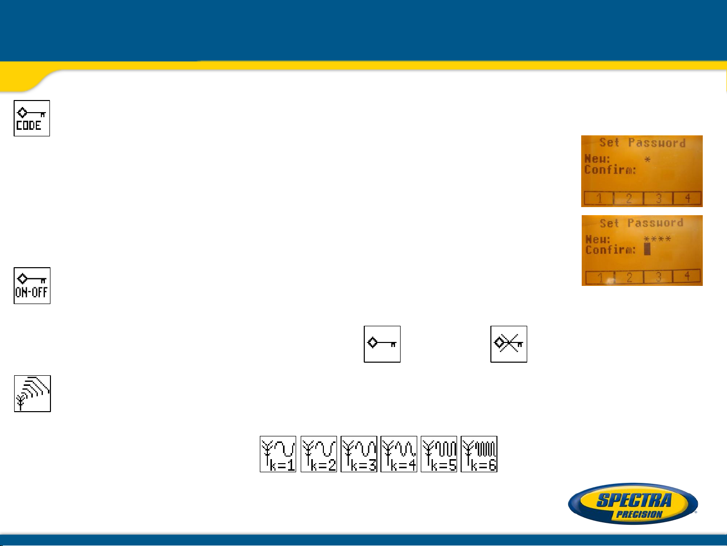
Set Password
Select the Set Password icon and press and release button 4 to open the Password menu.
Use button 1 to 8 to type in a password containing of 4 digits and repeat the password
at the second row.
Press and release button 4 to store the selected password; unit falls back to the
standard menu.
After powering up the unit, the standard display comes up if the correct password will
be entered, otherwise the unit turns off automatically.
Password On/Off
Select the Set Password ON-Off icon and press and release button 4 to open the Password menu.
Buttons 6/7 can be used to toggle between Password On and Password Off if a Password has been
entered before.
Press and release button 4 to confirm the selection.
Radio (RF) Channel
Select the RF Channel icon and press and release button 4 to open the Radio Channel menu.
The desired RF Channel: 1 to 6 can be selected using the buttons 6/7.
Press and release button 4 to
confirm the selected RF Channel.
Note: After changing the RF channel, the RC and HL needs to be paired again.
Setting Menu
Page 27

Select Language
Select the Language icon and press and release button 4 to open the Language menu.
Use button 5 to 8 to select the required local language (EN, DE, IT, FR, ES, PT, NL, DA, NO, SV, FI, PL, TR,
CZ).
Press and release button 4 to store the selected Language; unit falls back to the standard menu.
Position Info
when working with high grade values the product requires the position info to maintain accuracy and avoid
errors caused by different gravity. The user has the chance to provide the position info of the job site to
the product. This is the degree of latitude as well as the altitude.
Chose Settings and navigate to the sub menu position info. Press button 4 to activate the submenu. With
buttons 1 and 2 the different values can be increased/decreased. Also ‚+‘ or ‚-‘ for the latitude can be
changed with buttons 1 and 2. With buttones 5, 6, 7 and 8 the cursor position can be changed.
Restore to default: scroll down to ‚Default position‘. Press button 1 (Set); the unit will change to default
values; press button 4 to confirm the change.
Setting Menu
Page 28

Any error message can be deleted with a short press of button 4 (OK).
The table shows the related description and possible solutions.
The next service center should be contacted if a different error message as shown at the table will be displayed.
Error Messages
Error
codes
Description
Solution
21
Temporary EEprom problem
Repeat pairing and re
-enter the customer settings
120
HI alert
- Unit Heigt changed
Check laser beam elevation
130
Mechanical Limit during Axis Alignment or Grade
Match
Re
-align the closer to the alignment point; check if existing
slope is above +/
-25%
131
Rake Angle Limit
Pre
-tilt the unit closer to the alignment point
140
Laser beam blocked
Make sure there are no obstacles between the transmitter
and the
HL750
141
Time Out
- Alignment could not be completed in the
allowed time
Check radio operating range/ connection; check stable laser
setup
150
No receiver
- Receiver not available for single axis
automatic function
Make sure the receiver is on and paired
152
No receiver
- The laser searched for the receiver but
could not find it
Check the operating range for auto function and restart the
auto alignment
153
Lost Receiver
- The laser searched and found the
receiver but then lost it
Check the operating range for auto function and restart the
auto alignment
160
X or Y level
sensor defect
Contact service center
 Loading...