

Page 1

Quick Start Guide
Page 1Soundcraft® Si Series Quick Start Guide
Page 2

Page 2 Soundcraft® Si Series Quick Start Guide
IMPORTANT
Please read this manual carefully before using
your mixer for the rst time.
INTRODUCTION
Firstly, thanks for choosing the Soundcraft Si Series!
This Quick Start Guide will give you a good overview of the main features
of the console and will allow you to get up and running in the minimum
amount of time.
This guide will show you how to:
1. Power Up the console
2. Create a new SHOW
3. Get familiar with the OLED displays
4. Connect an Input Source
5. Use GLOBAL MODE to adjust Gains and Pans
6. Apply EQ and Dynamics
7. Add Lexicon Effects
8. Create Aux and Sub-Group Mixes
9. Create a Matrix Mix
10. Create VCA and Mute Groups
11. Store and name Snapshots
Page 3
Page 3Soundcraft® Si Series Quick Start Guide
OK, let’s get started!
For this tutorial section we will assume that you have the Left/Right Master Outputs
of the console connected to an amp/speaker combination of some kind.
POWERING UP
Press the SYSTEM ON/OFF button on the console. Wait for the console to power up.
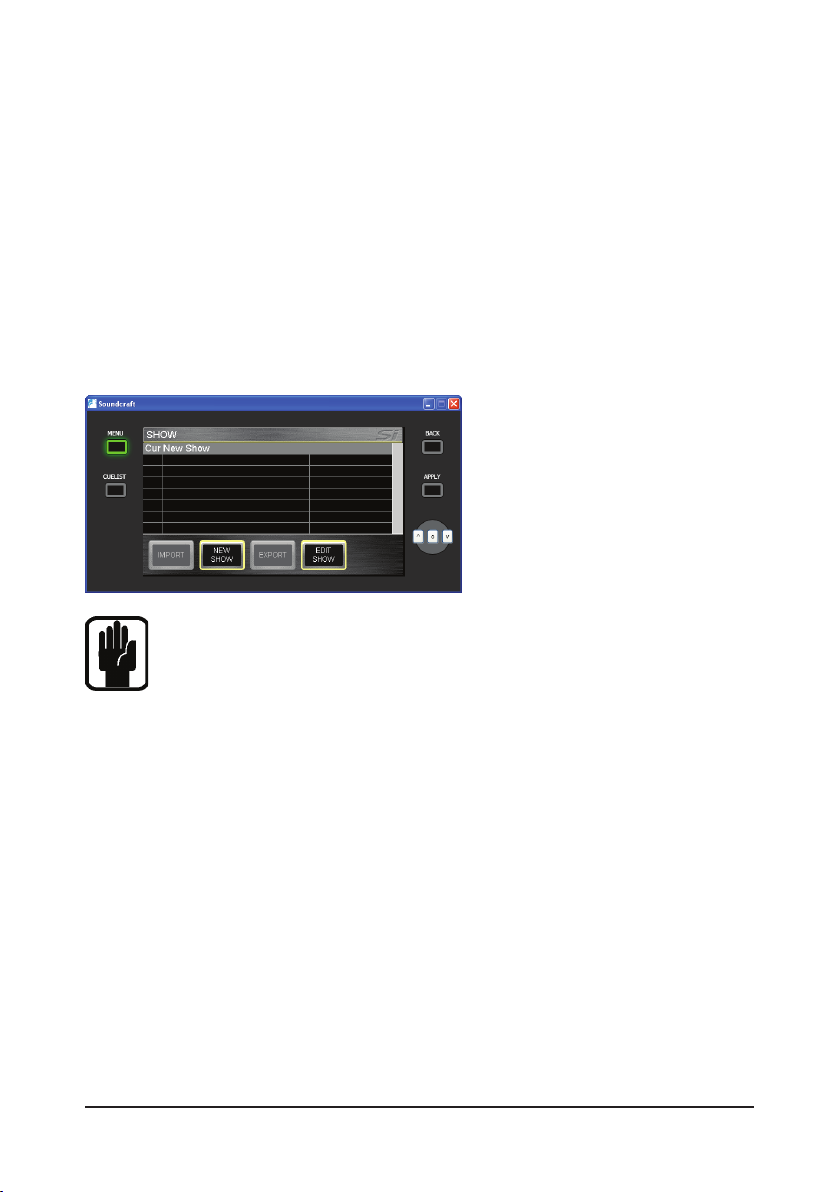
CREATE A NEW SHOW
Press the MENU button and then
select the SHOW tab on the touch
screen.
Now press the NEW SHOW tab.
Note! Pressing the NEW SHOW tab will clear the existing Show and Cue
List. All current console settings will be lost and the console returned to its
default state.
NAMING THE NEW SHOW
Press the EDIT SHOW button and scroll to the Show Name eld. Press the ADJUST
knob to call up the Alpha/Numeric keypad display. Enter the new show name.
Press the APPLY button to store the name of your new SHOW.
Page 4
Page 4 Soundcraft® Si Series Quick Start Guide
Upper OLED Zone
A + sign indicated a
second function is
available by pressing
the encoder
Channel Name or ID see page 2-7
Displays LR_, __C,LRC or LCR depending on
channel type and routing/pan mode selected
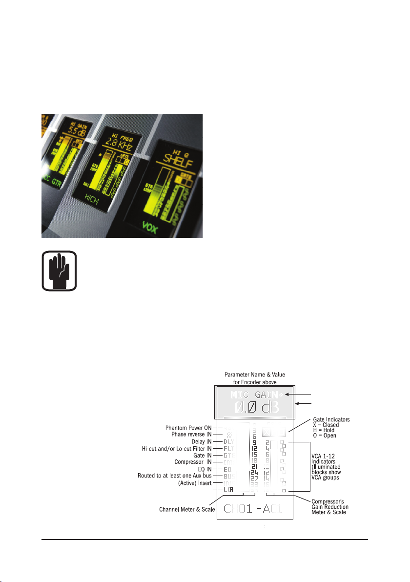
THE OLED DISPLAY
The OLED display (Organic LED) is central to the operation of the console and gives
you a lot of very useful information about the input channels and the encoders
located above them.
The OLED display is divided into three
sections with the top section (the
ORANGE part) always describing the
function of the encoder situated directly
above it.
The bottom section (the GREEN part)
gives the name of the channel located
below it.
Note! If you press the ‘i’ button the name of the physical connector that
the input channel is connected to will appear. This is very useful if you
have renamed your channels and need to nd out where the input is
derived from.
The area in the middle (the YELLOW part) gives information specic to the channel
below it. This includes metering for Input Levels, Noise Gate activity and Compressor Gain Reduction. There are also status icons for VCA assignments and any
switches associated with the input channel (48v active, Phase active, EQ In etc.)
The OLED displays allow the user to see
at a glance exactly what is happening on
any of the input channels.
The diagram explains
what is displayed
on the OLED.
Page 5
Page 5Soundcraft® Si Series Quick Start Guide
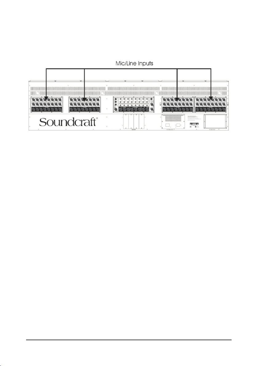
CONNECT AN INPUT SOURCE
Mic/Line Inputs (Soundcraft Si3 shown)
The Mic/Line Inputs on the rear of the console are arranged in 3 or 4 identical
blocks with 16 Inputs and 8 Outputs on each giving a total of 64 (48 on Si2) Mic
inputs. Each block of I/O is labelled either A, B, C or D and these blocks of inputs
are mapped to the faders as follows:
Soundcraft Si3
Mic Inputs A 1-16 (inputs 1-16) Layer A - Faders 1-16 Left Hand side
Mic Inputs B 1-16 (inputs 17-32) Layer A – Faders 17-32 Right hand side
Mic Inputs C 1-16 (inputs 33-48) Layer B - Faders 1-16 Left Hand side
Mic Inputs D 1-16 (inputs 49-64) Layer B – Faders 17-32 Right hand side
Soundcraft Si2
Mic Inputs A 1-16 (inputs 1-16) Layer A - Faders 1-16 Left Hand side
Mic Inputs B 1-16 (inputs 17-24) Layer A – Faders 17-24 Right hand side
Mic Inputs C 1-16 (inputs 25-40) Layer B - Faders 1-16 Left Hand side
Mic Inputs D 1-16 (inputs 41-48) Layer B – Faders 17-24 Right hand side
In addition to the mono inputs, there are also 4 Stereo Inputs located in the centre
section of the rear panel, which areavailable on Layer C or D on the right hand
section of the console, depending on whether you have an Si2 or Si3.
Soundcraft Si3 Stereo Inputs 1-4 Layer D - Faders 25/26/27/28
Lexicon Returns 1-4 Layer D - Faders 29/30/31/32
Soundcraft Si2 Stereo Inputs 1-4 Layer C & D - Faders 17, 18, 19, 20
Lexicon Returns 1-4 Layer C & D - Faders 21, 22, 23, 24
Page 6
Page 6 Soundcraft® Si Series Quick Start Guide
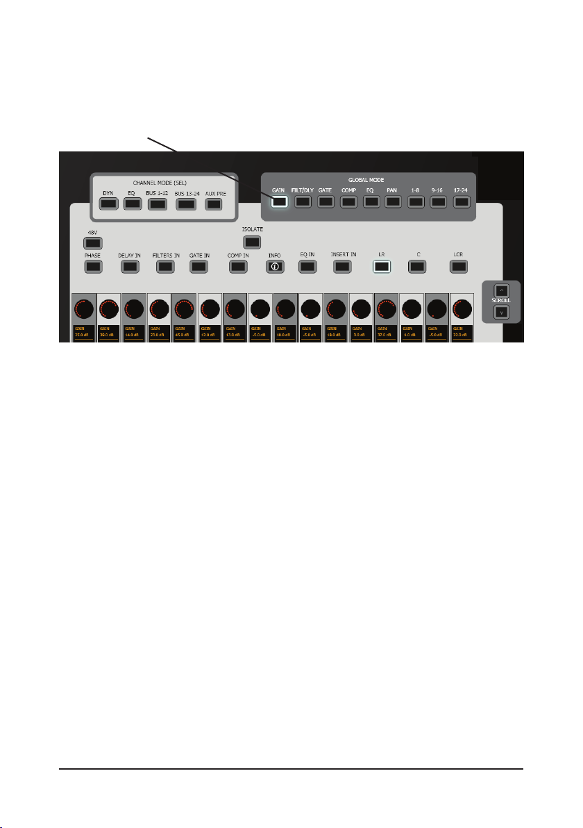
Before we go on, here’s a quick word about GLOBAL MODES
In GLOBAL MODE the encoder above each channel fader can be used to simulate
the facilities found in the horizontal plane of a traditional analogue console
e.g. Gains, Filters, EQ, Aux Sends and Pans.
Pressing the appropriate GLOBAL MODE button will assign that function to the
encoders and the top section of the OLED display will let you know what the en-
coder is about to do.
Page 7
Page 7Soundcraft® Si Series Quick Start Guide
ADJUSTING THE GAIN AND PAN OF THE INPUT SIGNAL
Connect an audio source to Mic/Line Input A1.
Press the GAIN button in the Left hand section.
You can now adjust the GAIN control (encoder) just as you would on an analogue
console and monitor the amount of input level on the Input Level Meter in the
associated OLED display.
If the input level is too high the CLIP arrow symbol will appear next to the
Input Meter. If this happens back off the input gain a little until it extinguishes.
Page 8
Page 8 Soundcraft® Si Series Quick Start Guide
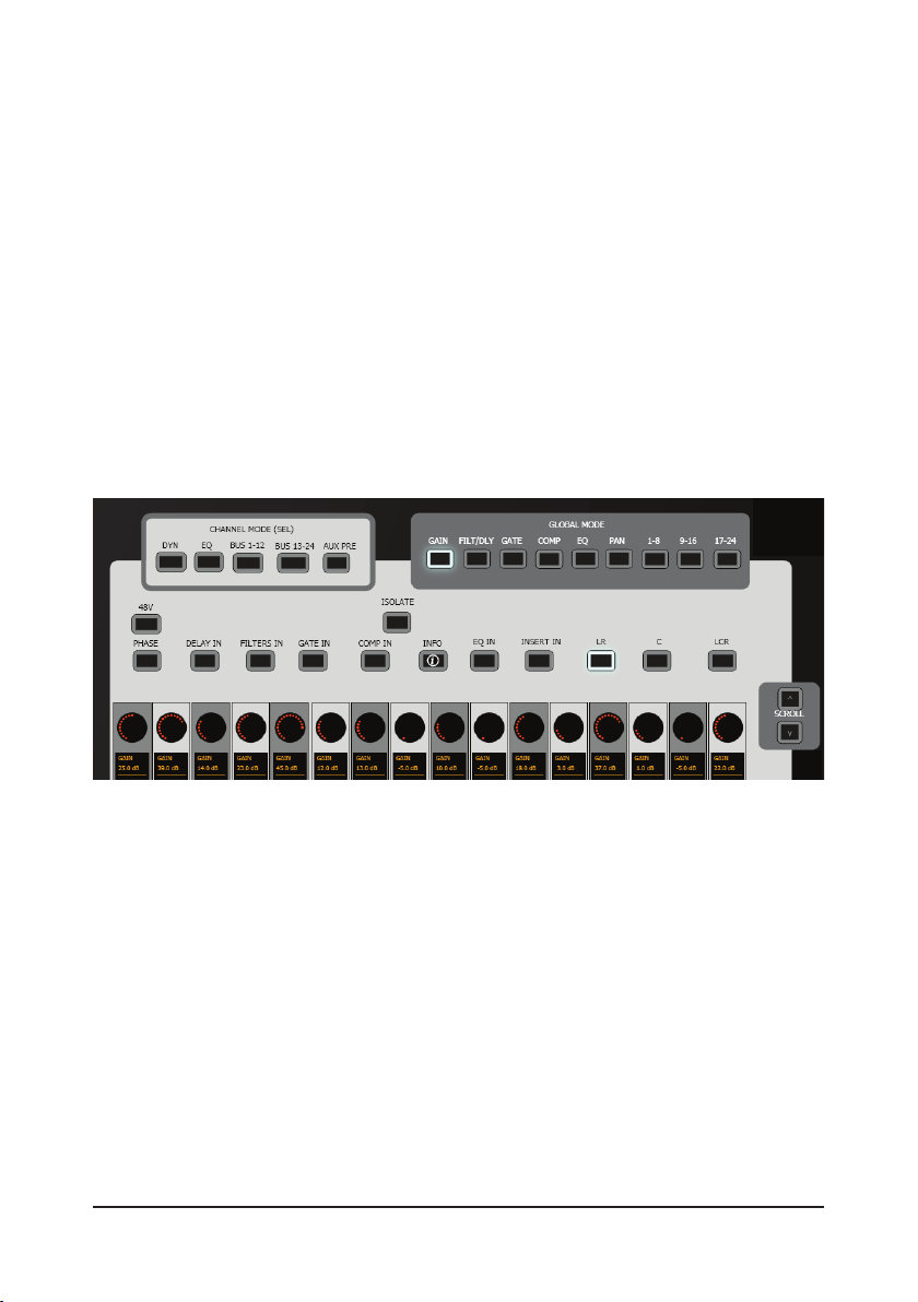
The following functions are available for selection via dedicated buttons:
GAIN•
FILTERS/DELAY •
GATE•
COMPRESSOR•
EQ•
PAN•
BUS 1-8•
BUS 9-16•
BUS 17-24 •
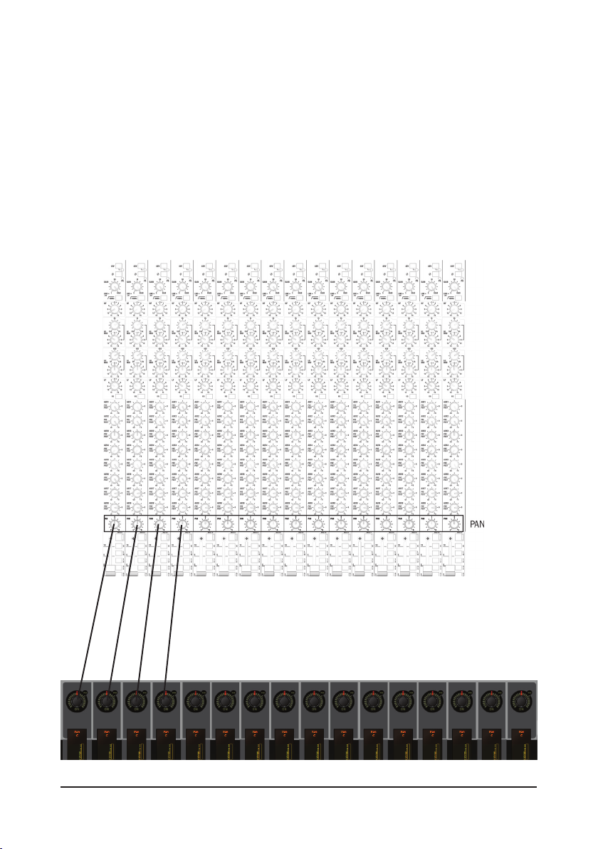
In the example below the GAINS button has been selected and therefore the
encoders are adjusting the input gains for the associated channels.
ADJUSTING THE PAN POSITION OF THE CHANNEL
Press the PAN button in the GLOBAL MODE area. This will cause the row of
encoders to function as PAN controls for their associated input channels
You may now adjust the PAN position by rotating the encoder. The top section of
the OLED display will conrm the actual numeric value for the chosen position.
Now experiment with other GLOBAL functions. Note that for functions with more
than 1 parameter, the SCROLL keys illuminate, allowing you to control those
parameters.
Page 9
Page 9Soundcraft® Si Series Quick Start Guide
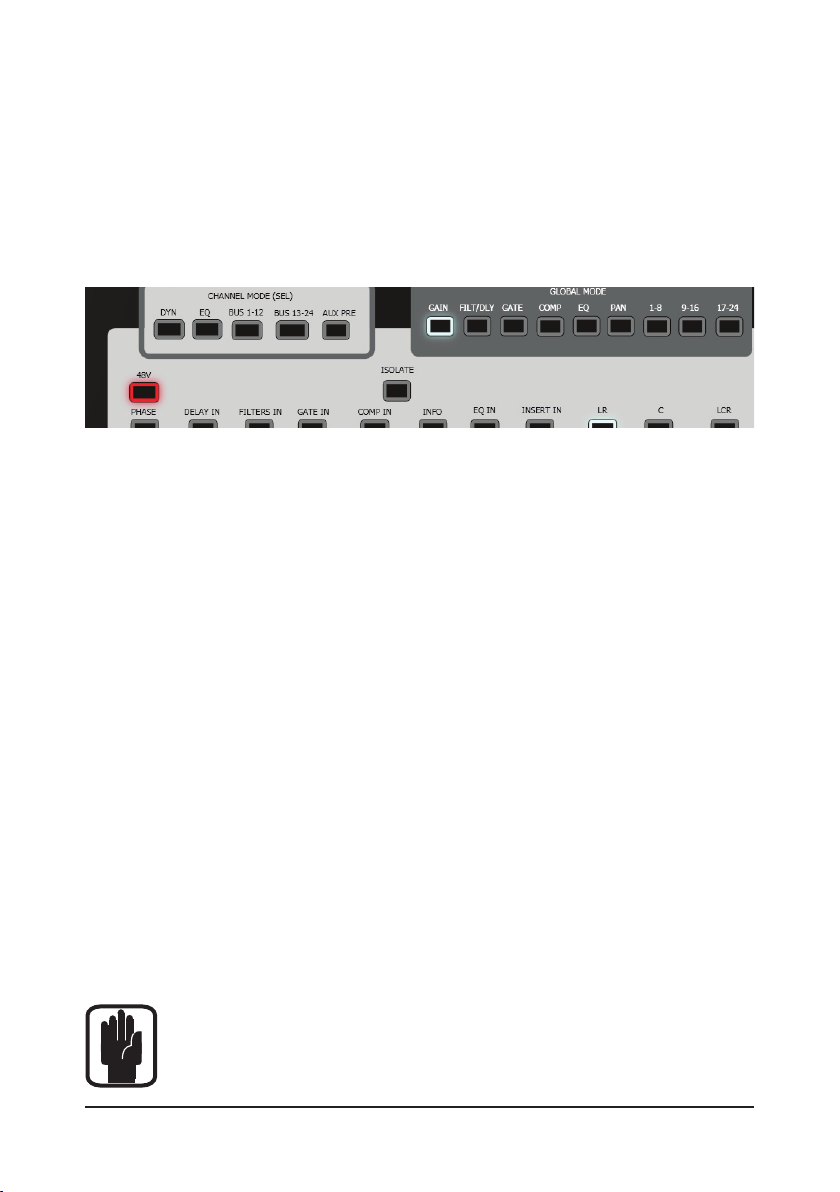
DO YOU NEED 48V PHANTOM POWER?
Press and hold the 48V button in the CHANNEL MODE section (this will put the
control surface into INTERROGATE mode – see below for further details) and then
press the SEL button above the channel (or channels) that you want to turn that
function on for. You will see that the SEL buttons will illuminate ORANGE and the
48V icon will appear in the OLED display for the
relevant channels.
INTERROGATE MODE
This mode is very useful for making multiple switch assignments for the input
channels just as you would on an analogue console. For example, on an analogue
console you might want to switch 48V power on for several channels, or you might
want to switch on the EQ IN buttons for a number of channels and this would be
achieved using dedicated switches on each input channel strip. On the Si Series
the INTERROGATE mode allows you to do the same thing.
Press and hold the button you want to switch on for a number of channels (for
example 48V), and then press the SEL buttons on the relevant channels. The OLED
display will conrm the selections you have made.
INTERROGATE mode is only relevant for the currently displayed input fader bank
and you cannot switch between banks while making selections. This mode is also
useful for checking assignments for input channels. By pressing the relevant button (e.g. EQ IN) the SEL buttons will illuminate for any input channel that has that
button assigned to it allowing you to see at a glance what assignments have been
made. Any of the buttons in the CHANNEL MODE area can be used to
INTERROGATE the control surface.
Note! When you are using Interrogate mode you can also press the
CLEAR button to clear any current selections. This should be used
carefully though!
Page 10

Page 10 Soundcraft® Si Series Quick Start Guide
APPLYING EQ AND DYNAMICS
There are a couple of different ways to control the EQ and Dynamics for the input
channel you are working on. In this example we are going to use the encoders in
the Centre Section of the console.
The 24 encoders are used in three modes:
UPPER ROW (these are the ones at the top!)•
LOWER ROW (the ones at the bottom!)•
BOTH ROWS (This is where both Upper and Lower rows are used together)•
UPPER ROW Section for EQ
Select INPUT EQ and OUTPUT EQ in the UPPER ROW section. You will notice that
one of the buttons will illuminate GREEN and the other ORANGE. This is because
the GREEN button is the active one and the ORANGE one is in standby or ‘primed’
mode. See below.
Select an input, and its EQ will be displayed and may be controlled from here.
Page 11

Page 11Soundcraft® Si Series Quick Start Guide
Note! The LF and HF EQ bands have a switchable PEAK/SHELVING facility
that is activated by pressing the encoder. (By the way any encoder that
has a ‘+’ symbol displayed in the OLED below it can be pressed to reveal
a 2nd mode function).
LOWER ROW Section for Dynamics
Select INPUT DYN and OUTPUT DYN in the LOWER ROW section. You will notice that
one of the buttons will illuminate GREEN and the other ORANGE. This is because
the GREEN button is the active one and the ORANGE one is in standby or ‘primed’
mode. See below.
You will notice that the upper row of encoders and OLED displays are now
congured as a 4 Band EQ and the lower row as a dynamics processor. Like the
EQ, the controls will follow the last selected channel.
A NOTE ON ‘STANDBY’OR ‘PRIMED’ MODE
As mentioned above you will see that the INPUT EQ and OUTPUT EQ buttons are
either GREEN or ORANGE (This is the same for the INPUT DYN and
OUTPUT DYN buttons). This is because these functions will switch between Input
and Output processing depending on which was the last input or output SEL
button pressed.
If you press a SEL button on an input channel the INPUT EQ and INPUT DYN
buttons will turn GREEN, while the OUTPUT EQ and OUTPUT DYN buttons light
orange.
If you press a SEL button on an Output Channel, this is reversed.
Page 12

Page 12 Soundcraft® Si Series Quick Start Guide
A word about ‘CHANNEL MODE’
In this mode all of the encoders and upper OLED zones are used together to
display and change settings for one selected channel. This collective function is
called the Virtual Channel Strip (VCS).
The VCS concept is best understood when compared with a typical analogue
channel strip as shown below. In this example the EQ controls of channel 6 are
highlighted. This corresponds to the SEL button of channel 6 being active, and the
EQ button from the Channel Mode options being selected.
The highlighted controls in the analogue equivalent above represent what will be
displayed on the VCS, which is displayed to the right of it, the VCS has been rotated
through 90° to make the comparison more complete.
Page 13

Page 13Soundcraft® Si Series Quick Start Guide
ADDING A COMPRESSOR OR A NOISE GATE TO THE INPUT
CHANNEL
Here, we will use the ‘Channel Mode’ view.
Make sure you have pressed the SEL button above the input channel you want to
process, and press the ‘CHANNEL MODE’ DYN key to place the GATE +
COMPRESSORS for the selected channel across the 16 encoders.
Press the GATE IN or COMP IN button in the CHANNEL MODE area to switch the
Gate or Compressor function on.
You can now use encoders in the
LOWER ROW to adjust the
settings for the GATE or
COMPRESSOR. You will see GATE
and COMPRESSOR activity start
to occur on the OLED screen
above the input channel you are
processing.
Page 14

Page 14 Soundcraft® Si Series Quick Start Guide
APPLYING LEXICON EFFECTS
The Si Series has 4 onboard Lexicon effects processors that offer a wide range of
top quality digital effects.
Effects Sends
Each one of the processors 1 to 4 is fed from bus sends 21 to 24 respectively. The
Lexicons cannnot be repatched, but the buses can be used as additional mix
busses by turning the ‘insert’ off as described on page 17.
Press the 13-24 button in the OUTPUT
FADERS SELECT section.
You will see that the last 4 faders are
used to control the master effects send
level for LEX 1, LEX 2, LEX 3 and LEX 4
and that the faders are illuminated LIGHT
BLUE.
Effects Returns
The stereo effects return levels for each of these processors are controlled by faders on the right hand section, numbers 29, 30, 31 and 32 in FADER LAYER D (or
21, 22, 23 and 24 on an Si2, on layer C or D). The fader slots are illuminated in
LIGHT BLUE to show that they are used exclusively for controlling Lexicon effects
levels.
ADDING AN EFFECT TO AN INPUT SIGNAL
There are a few different ways of sending input channels into the Lexicon proces-
sors, but for this example we will keep as close to the traditional analogue
approach as we can.
Page 15

Page 15Soundcraft® Si Series Quick Start Guide
Firstly press the 13-24 button in the OUTPUT FADERS SELECT section. Make sure
that the LEX1 bus master (fader 9) is positioned at the 0dB point and that the ON
button is illuminated.
Now go to the right hand bank of input faders (faders 17-32) and select the bank
D button in the INPUT FADERS SELECT section. You will notice that the last 4
faders are illuminated LIGHT BLUE. These are the Lexicon Effects Returns. Make
sure these are at the 0dB position and that the ON button is illuminated.
Now return to the input fader bank that was controlling the input channels you
have sent an input signal to.
In the GLOBAL MODE section press the BUS 17-24
button and then use the SCROLL arrow buttons to
locate LEX1.
You now have a dedicated effects send control for
each of the input channels.
Locate the encoder above the channel you want to
send to the Lexicon processor and press it to switch
it on (The ON light will illuminate).
You can now rotate the encoder to send the signal into the Lexicon effects
processor. You should be able to hear the effect progressively increasing as you
increase the amount of signal being sent to the Lexicon processor.
Note! If you press and hold the encoder that you are using as an effect
send to the Lexicon processor it will automatically switch on and set the
send level to 0dB. This is a fast method of setting basic levels.
Page 16

Page 16 Soundcraft® Si Series Quick Start Guide
There are two ‘press and hold’ functions for the encoders:
1. If the aux/effects send encoder is currently switched Off, then pressing
and holding it down will switch it on and set the send level to 0dB.
2. If the aux/effects send encoder is currently switched On, then pressing
and holding it down will switch it Off and set the send level to minimum (-innity).
CHANGING THE LEXICON EFFECT TYPE.
To change the Lexicon effect type for Lexicon 1 press the LEXICON button in the
UPPER ROW area found in the centre section of the console.
You will now see that there are 4 Lexicon processors assigned to the upper row of
encoders. The touch screen will also be showing the menu screen for the 4 Lexicon
processors each with the currently active effect preset displayed. Use the ADJUST
knob to the right of the touch screen to scroll to the processor you want to edit and
then press the Adjust knob to select the processor for editing the FX type.
You may now scroll through the drop down list to select the effect you want to use.
Press the ADJUST knob again to select the desired effect preset.
Note! You will notice that each of the 4 Lexicon processors has three
basic parameters available for adjustment. These are the most
important parameters required for each effect type. If you require more
detailed parameter adjustment, then press the EXPAND button located in
the bottom left corner of each Lexicon processor section.
Page 17

Page 17Soundcraft® Si Series Quick Start Guide
Pressing EXPAND will cause the selected processor to ‘expand’ across all 12
encoders allowing detailed parameter adjustment. Once you have completed your
adjustments, press the CLOSE button to return to the ‘compressed’ view.
CREATING AUXILIARY MIXES AND SUB-GROUPS
The Si Series has 24 buses that can be congured as Auxiliary Sends (e.g. for
creating monitor or FX mixes) or as Sub-Groups. These buses can also be
congured as mono or stereo Auxiliary Sends or Sub-Groups.
Note! Stereo pairs can only be created by combining Odd/Even numbered buses e.g. 1/2, 3/4, 5/6 etc.)
Buses that are congured as Auxiliaries have faders illuminated YELLOW, buses that
are congured as Sub-Groups will be illuminated GREEN.
Note! The default state of the console is that Buses 1-20 are congured
as Aux Send Masters and Buses 21-24 as Lexicon Effects Send Masters.
Note! The FX buses can be used as Aux/Monitor sends. Call up the BUS
MASTERS to BOTH ROWS then hit the BUS PRE button, now pressing the
Bus Master encoders will toggle the bus sends Pre / Post fade from all
channels, and remember that individual channels can be easily reversed
by using the AUX PRE function on the channel VCS if you need some sends to be
different from others. Then ‘un-select’ the INSERT for these four buses (8th button
in on the top row in OUTPUT PROCESSING) and now you have a ‘clean’ mix!
Page 18

Page 18 Soundcraft® Si Series Quick Start Guide
CONFIGURING AND NAMING BUSES
Press the MENU button next to the touch screen, then press the BUS tab on the
touch screen. Press the SEL button above the Bus you want to congure e.g. Bus
19. You will notice that the top line of the touch screen display will read ‘BUS 19
SETUP’
BUS NAMING
The top line of this display reads ‘Bus Name – BS19’. Select this line and press
the ADJUST knob to bring up the alpha/numeric key pad. You may now change the
name of this Bus and then press the APPLY button to activate the new name. This
new name will appear in the OLED display above the fader.
Page 19

Page 19Soundcraft® Si Series Quick Start Guide
Press the BACK button to exit the naming page and return to the BUS 1 SETUP
display.
BUS TYPE
Scroll down to the Bus Type line. In default state this should read ‘Aux Bus’
Press the ADJUST button and you can now change between ‘Aux Bus’ and ‘Group
Bus’ . Press the ADJUST button to conrm your selection.
You will notice that the faders change colour to indicate the selection you have
made.
Note! From this page you may select the ‘PRE’ fade send to be PRE or
POST EQ.
STEREO LINKING
Any Odd/Even numbered pair of buses can be linked with the exception of the 4
Lexicon buses which are always mono. Scroll down to the Bus Width line. In default
state this should read ‘Mono’. Press the ADJUST button and you can now change
between ‘Mono’ and ‘Stereo’, then press the ADJUST button to conrm your selec-
tion. You will now notice that the faders are linked for stereo operation.
Note! In this scenario one fader acts as the master and the other as the
slave. If you try to move both faders together you will feel resistance.
Use a single member of the linked pair to make level adjustments.
Page 20

Page 20 Soundcraft® Si Series Quick Start Guide
MAKING CONTRIBUTIONS TO AN AUX BUS
For this example we will use Bus 01. Press the 1-12 button in the OUTPUT FADER
SELECT area, position the fader for Bus 01 at the 0dB position and make sure the
ON button is illuminated.
Press the BUS 1-8 button in the GLOBAL MODE section. Use the SCROLL
arrow buttons to select Bus 01 to the encoders. Press the encoder above the
channel you want to send to the Aux 01 bus (Bus 01) to switch it ON.
You can now rotate the encoder gradually to increase the amount of signal being
sent to the Aux 1 bus (Bus 01).
MAKING CONTRIBUTIONS TO AN AUX BUS USING
‘FOLLOW’ MODE
For this example we will again use Bus 01, but now will use the ‘channel faders’ as
the aux send controls.
Continuing from above, press the FADERS FOLLOW key and SELect Bus01. The
faders (1-6 or 1-24) no illuminate yellow and move to represent the send levels
from the channels to Bus 01. The level is turned up or down with the fader and on
or off with the ON key.
Note! If you still have the encoders in GLOBAL mode for Bus 01, you will
see the faders and encoders track each other.
Page 21

Page 21Soundcraft® Si Series Quick Start Guide
ROUTING INPUT CHANNELS TO A SUB-GROUP
For this example we will use Bus 01.
Press the 1-12 button in the OUTPUT FADER SELECT area.
Position the fader for Bus 01 at the 0dB position and make sure the ON button is
illuminated.
Change BUS 01 into a Group as described. You will notice its colour changes to
GREEN.
Press the BUS 1-8 button in the GLOBAL MODE section.
Use the SCROLL arrow buttons to select Bus 01 to the encoders.
You will notice that the ORANGE LED ring around the encoder has disappeared
because the bus has been congured as a Group and has no vriable level control
parameters, only On or Off.
Press the encoder above the channels you want to route to Group 01 (Bus 01).
The ON window will illuminate to show that routing has occurred.
You will see level displayed on the Bus 01 Output Meter in the BUS OUTPUTS meter
section.
Page 22

Page 22 Soundcraft® Si Series Quick Start Guide
CREATING A MATRIX MIX
The Si3 has 8 Matrix buses that can receive signals from the Left, Right and Centre
Buses and also the 24 Aux/Group buses.
You can create Matrix mixes in two ways.
Multiple Buses to a single Matrix output:
This method allows the fast creation of a sub-mix of all 24 buses plus the Left,
Right and Centre buses to a single Matrix output.
Press the BUS TO MATRIX button in the BOTH ROWS section and press the
MTX/LRC button in the OUTPUT FADERS SELECT section
You can now press the SEL button above the Matrix master fader you want to send
audio to. The 24 encoders in the central section will be congured as send
controls for buses 1-24 to the SELected bus.
Pressing the LRC button will toggle the last 3 encoders between LEX2/LEX3/LEX4
and LEFT/RIGHT/CENTRE, allowing sending LCR signals to the matrix.
Press the encoders to switch them ON and send the amount of level you require
from each bus to the selected Matrix output.
Page 23

Page 23Soundcraft® Si Series Quick Start Guide
Note! Pressing and holding any of the 24 encoders will switch them
On and set the level sent to the selected Matrix output to 0dB. (If the
encoder is already switched On then this method will not work).
A single bus to multiple matrix outputs
This method allows a single bus to quickly be sent to any or all of the 8 Matrix
Outputs.
Press the MATRIX SENDS button in the LOWER ROW
section. You will notice that the rst 8 encoders in the Lower Row are congured as
master Matrix level controllers. In the OUTPUT FADERS SELECT area select the bus
you want to send to the Matrix outputs by pressing 1-12, 13-24 or MTX/LRC .
Press the SEL button above the bus you want to send into the matrix.
You can now turn up the individual sends from the SELected bus to each of the 8
Matrix outputs found in the Lower Row.
Note! Pressing and holding any of the 8 encoders will switch them On
and set the level sent to the selected Matrix output to 0dB. (If the
encoder is already switched On then this method will not work).
Page 24

Page 24 Soundcraft® Si Series Quick Start Guide
CREATING VCA AND MUTE GROUPS
The Si3 has 12 VCA Groups and 8 Mute Groups to which any input channel can be
assigned.
Creating VCA Groups:
Press the SETUP button in the VCA/MUTES section. You will notice that the 12
Output faders turn DARK BLUE, the SEL buttons turn YELLOW and the VCA button
illuminates in the OUTPUT FADERS SELECT section.
Press the SEL button above the VCA Master fader you
wish to assign some input faders too – it will turn WHITE.
You may now press the SEL buttons above any of the
input channels you want to assign to that VCA Group.
You will also notice that the small blocks on the right
hand side of the OLED displays above the channels you
have assigned to the VCA Group will turn solid to represent the chosen VCA
assignment. To exit this mode press the SETUP button
again.
Note! If you are making selections you may see other layer buttons
illuminated blue. The blue illumination is to indicate that there are
‘hidden’ channels assigned to the selected VCA Group although in this
case they are the same as the assignments made in Layer A. This will
also occur between layers B and D.
Page 25

Page 25Soundcraft® Si Series Quick Start Guide
Creating MUTE Groups.
Press the SETUP button in the VCA/MUTES section. You will notice that the 8 USER
DEFINED buttons will illuminate YELLOW.
Press the one of the USER DEFINED buttons to create a Mute Group Master – it will
turn RED.
You may now press the SEL buttons above any of the input
channels you want to assign to that Mute Group. The SEL
buttons will turn ORANGE when selected.
To exit this mode press the SETUP button again.
Note! If you are making selections in input fader layer
A you may see other layer buttons illuminated red. The
RED illumination is to indicate that there are ‘hidden’ channels
assigned to the selected Mute Group although in this case they
are the same as the assignments made in Layer A. This
will also occur between layers B and D.
Page 26

Page 26 Soundcraft® Si Series Quick Start Guide
STORING SNAPSHOTS
The Si Series has the ability to store ‘Snapshots’ of the control surface settings so
that they can be recalled at a later date. This is very useful for storing different
console setups for example in a situation where there might be 2 or 3 different
artists performing who each require completely different console settings.
Storing a basic Snapshot
To store a snapshot press the STORE button in the CUE CONTROL section at any
time. A new snapshot will be created and added to the Cue List.
Naming a snapshot
Press the EDIT CUE tab and scroll to the Cue Name eld in the display. Press the
ADJUST knob to bring up the Alpha/Numeric keypad and enter the new name.
Press the APPLY button to apply the new name.
Page 27

Page 27Soundcraft® Si Series Quick Start Guide
Viewing the Cue List
Press the CUE LIST button next to the touch screen to bring up the current Cue List.
Use the adjust wheel to select a CUE, then RECALL to play cues out of sequence.
Updating an existing snapshot
If you wish to update an existing snapshot instead of creating a new one, recall the
original snapshot, make the adjustments, view the cue list, then press the UPDATE
button in the Cue List window.
Page 28

© Harman International Industries Ltd. 2009 All rights reserved
Parts of the design of this product may be protected by worldwide patents.
Part No. BD10.520001
Soundcraft is a trading division of Harman International Industries Ltd.
Information in this manual is subject to change without notice and does
not represent a commitment on the part of the vendor. Soundcraft shall
not be liable for any loss or damage whatsoever arising from the use of
information or any error contained in this manual.
No part of this manual may be reproduced, stored in a retrieval system, or transmitted,
in any form or by any means, electronic, electrical, mechanical,
optical, chemical, including photocopying and recording, for any purpose without the
express written permission of Soundcraft.
Harman International Industries Limited
Cranborne House
Cranborne Road
POTTERS BAR
Hertfordshire
EN6 3JN
UK
Tel: +44 (0)1707 665000
Fax: +44 (0)1707 660742
www.soundcraftdigital.com
Page 28 Soundcraft® Si Series Quick Start Guide
 Loading...