


Quick Start Guide
XG 430/450 Rev. 2
Before you begin please confirm that you have a working Internet connection and make sure you have the account information available that was provided by your ISP.
1. Before Deploying
Congratulations on the purchase of your Sophos XG device. This Quick Start Guide describes in short steps how to connect your device and explains how to open the web-based Admin Console from your administration PC. The Admin Console allows you to configure every aspect of the device.
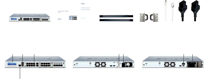
a) What does the box include
|
|
|
|
|
|
Micro USB cable |
|
|
|
|
|
|
|
|
|
|
|
|
|
|
|
|
|
|
|
|
|
XG 430/450 |
This Quick Start Guide and |
2 rack mount rails |
2 rack |
RJ45 Ethernet cable |
||
(1U rack mount chassis) |
Security Notes |
|
mount brackets |
2 power cable |
||
|
|
|
|
|
|
|
b) Device Images*: Front and Back
XG 430/450 Rev. 2 |
XG 430 Rev. 2 |
|
|
XG 450 Rev. 2 |
|
Multi-function |
1 x COM |
8 x 10/100/1000 |
Connector for redundant |
Power |
|
LCD display |
(RJ45) |
Base-TX ports |
external power supply |
supply |
Power switch Power supply |
|
|
|
|
|
|
|
|
|
|
|
|
|
|
|
|
|
|
|
|
|
|
|
|
|
|
|
|
|
|
|
|
Navigation |
Micro USB |
2 x |
2 further expansion bays |
1 x HDMI |
|
Power switch |
1 x HDMI |
|
Optional |
||||||
for LCD |
2 x |
SFP+ |
(shown here with optional |
|
1 x |
|
|
|
1 x |
power supply |
|||||
|
|
USB 3.0 |
Ports |
FleXi Port module) |
USB 3.0 |
|
|
USB 3.0 |
|
|
|||||
1 x Management
port (IPMI)
* The displayed front image is of XG 450 device. The XG 430 device may vary slightly.
Quick Start Guide XG 430/450 Rev. 2 |
1 |

Internet
|
|
|
|
|
|
Port 2/WAN |
|
|
|
|
|
|
|
|
|
|
|
|
|
|
|
|
|
|
|
|
||
|
|
|
|
|
|
|
|
|
|
|
|
|
|
|
|
|
|
|
|
|||||||||
|
|
|
|
|
|
|
|
|
|
|
|
|
|
|
|
|
|
|
|
|
||||||||
|
|
|
|
|
|
|
|
|
|
|
|
|
|
|
|
|
|
|||||||||||
|
|
|
|
|
|
|
|
|
|
|
|
|
|
|
|
|
|
|
|
|||||||||
e.g., |
XG Appliance |
|||||||||||||||||||||||||||
DSL modem |
|
|
|
|
|
|
|
|
|
|
|
|
|
Port 1/ |
||||||||||||||
|
|
|
|
|
|
|
|
|
|
|
|
|
|
|
|
|
|
|
|
|
|
|||||||
|
|
|
|
|
|
|
|
|
|
|
|
|
|
|
|
|
|
|
|
|
|
|
|
|
LAN |
|||
|
|
|
|
|
|
|
|
|
|
|
|
|
|
|
|
|
|
|
|
|
|
|
|
|
|
|
|
|
|
|
|
|
|
|
|
|
|
|
|
|
|
|
|
|
|
|
|
|
|
|
|
|
|
|
|
|
|
|
|
|
|
|
|
|
|
|
|
|
|
|
|
|
|
|
|
|
|
|
|
|
|
|
|
|
|
|
|
|
|
|
|
|
|
|
|
|
|
|
|
|
|
|
|
|
|
|
|
|
|
|
|
|
|
|
|
|
|
|
|
|
|
|
|
|
|
|
|
|
|
|
|
|
|
|
|
|
|
|
|
|
|
|
|
|
|
|
|
|
|
|
|
|
|
|
|
|
|
|
|
|
|
|
|
|
|
|
|
|
|
|
|
|
|
|
|
|
|
|
|
|
|
|
|
|
|
|
Switch |
|||||||||||||||
|
|
|
|
|
|
|
|
|
|
|
|
|
||||||||||||||||
|
|
|
|
|
|
|
|
|
|
|
|
|
||||||||||||||||
|
|
|
|
|
|
|
|
|
|
|
|
|
||||||||||||||||
|
|
|
|
|
|
|
|
|
|
|
|
|
|
|
|
|
|
|
|
|
|
|
|
|
|
|
|
|
Internal network |
|
|
|
|
|
|
|
|
|
|
|
|
|
|
|
|
|
|
|
|
||||||||
admin client PC |
|
|
|
|
|
|
|
|
|
|
|
|
|
|
|
|
|
|
|
|
||||||||
2. Mount and connect the device
Please follow the rack mounting instructions as described in the XG Operating Instructions guide* or the separate instructions provided with your rack mount rails.
Connect the ports to the internal and external networks
1.Connect the Port 1/LAN port via a hub or switch to the internal network. For this purpose, use the RJ45 Ethernet cable provided. Note that your Administration PC must also be connected to this network.
2.Connect Port 2/WAN to the external network. The connection to the WAN depends on the type of Internet access.
The XG devices are shipped with the following default settings:
Ethernet Port |
|
IP Address |
|
Zone |
1 |
172.16.16.16/255.255.255.0 |
|
LAN |
|
2 |
|
DHCP |
|
WAN |
IPMI Interface |
|
IP Address |
|
Scope |
MGMT** |
|
|
Hardware monitoring |
|
|
192.168.1.1 |
|
||
Admin Console/ |
|
Admin Console/ |
|
CLI Console Password |
MGMT Username |
|
MGMT Password |
|
|
admin |
|
admin |
|
admin |
Default Gateway |
|
DNS proxy |
|
DHCP service |
DHCP |
|
Enabled |
|
Enabled |
|
|
|||
|
|
|
|
|
*Available at sophos.com/get-started-xg
**It is highly recommended to change the default IP Address/Username/Password of the IPMI MGMT interface.
Quick Start Guide XG 430/450 Rev. 2 |
2 |
3. Power Up the Device
Connect the power cable and turn on the device
Connect the device to the power supply using the power cable(s). Turn the device on. The power switch is on the back of the device and is placed next to the power connection. Once the device has booted completely, you’ll hear an acoustic signal: five beeps in a row.
4. Connect your Administration PC
Administration PC connection properties:
Use the settings below to configure your (PC/Laptop) network interface: ÌÌ IP address: 172.16.16.2
ÌÌ Netmask: Enter 255.255.255.0
ÌÌ Default Gateway: Enter the IP address of the device’s internal network card (Port 1/LAN): 172.16.16.16
ÌÌ DNS Server: Enable this option and enter the IP address of the internal network card (Port 1/LAN): 172.16.16.16
Connect your PC/Laptop to Port 1/LAN port of the device:
Start the browser and enter the management IP address of the device’s LAN port that your PC is connected to: https://172.16.16.16:4444 (Port 1)
Login with the default details below:
ÌÌ Username: admin ÌÌ Password: admin
Quick Start Guide XG 430/450 Rev. 2 |
3 |
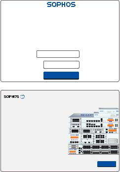
Device Management
Welcome
To your Sophos Device
To get started register your device below. Until you register you may only access and edit settings in “Basic Setup” and your device will remain unactivated.
Serial Number |
XXXXXXXXXXXXXXX |
Basic Setup
Register Device
Network Configuration Wizard
Secure your enterprise with
Sophos integrated internet security
Skip Start
5. Setup the device a) Register the Device
If you have not previously registered your device with your Sophos ID, you will see a registration screen. The device requires Internet connectivity for it to be registered with your Sophos ID. You can adjust the network settings of the device’s interfaces by clicking “Basic Setup” so that the device can connect to the Internet.
After clicking “Register Device”, you are redirected to the Sophos.com. If you already have a Sophos ID, enter your login credentials under “Sign in with your Sophos ID”. If you are a new user, sign up for a Sophos ID by entering the details under “Create Sophos ID”.
Click “Continue” to complete the registration process. Please wait while the process completes – it will take a few seconds. After successful registration, you will see
a screen with the message, “Your device is now registered”. Please note that you should proceed with the next step i.e. “Synchronize License” only after the device is successfully registered.
b) Synchronize License
Click “Initiate License Synchronization” to fetch license information from Sophos onto the device. After synchronization, you will see a screen with the message, “Synchronization with server was successful”.
c) Start Network Configuration
After successful synchronization, choose “Click Here” on the “Welcome” screen to start your initial device configuration. Use the Network Configuration Wizard to select the deployment mode (Bridge/Gateway) for your device, change the interface(s) IP addresses, default gateway, DNS settings and Date/Time Zone to match your local network settings.
Quick Start Guide XG 430/450 Rev. 2 |
4 |

d) Device LED Status
Power (LED Display)
Power Supply Acitve |
Green |
Power Supply Failure |
Red |
SSD Active |
Blue |
|
|
LEDs on each RJ45 Ethernet connector
ACT/LNK |
Green |
Constantly |
1. The Ethernet port is receiving power. |
(Left LED) |
|
|
2. Good connection between the Ethernet port and hub. |
|
|
Flashing |
The adapter is sending or receiving network data. The |
|
|
|
frequency of the flashes varies with the amount of traffic. |
|
|
Off |
1. The adapter and switch are not receiving power. |
|
|
|
2. No connection between both ends of network. |
|
|
|
3. Network drivers have not been loaded |
|
|
|
or do not function correctly. |
|
|
|
|
Speed |
Amber |
On |
The Ethernet port is operating at 1,000 Mbps. |
(Right LED) |
Green |
On |
The Ethernet port is operating at 100 Mbps. |
|
|
Off |
The Ethernet port is operating at 10 Mbps. |
Quick Start Guide XG 430/450 Rev. 2 |
5 |

LEDs on each SFP+ connector
ACT/LINK |
|
Green |
|
Constantly |
1. The SFP+ connector is receiving power. |
|
(Left LED) |
|
|
|
|
|
2. Good linkage between the SFP connector and hub. |
|
|
|
|
|
Flashing |
The adapter is sending or receiving network data. The |
|
|
|
|
|
|
frequency of the flashes varies with the amount of traffic. |
|
|
|
|
|
Off |
1. The adapter and switch are not receiving power. |
|
|
|
|
|
|
2. No connection between both ends of network. |
|
|
|
|
|
|
3. Network drivers have not been loaded |
|
|
|
|
|
|
or do not function correctly. |
|
|
|
|
|
|
|
Speed |
|
Blue |
|
On |
The SFP+ connector is operating at 10,000 Mbps. |
|
(Right LED) |
|
Amber |
|
On |
The SFP+ connector is operating at 1,000 Mbps. |
|
|
|
|
|
|
Off |
Either the LED is not working or the SFP+ connector |
|
|
|
|
|
|
is operating at a speed below 1,000 Mbps. |
|
|
|
||||
LAN Bypass (LED Display) |
|
|||||
LAN Bypass Active |
|
Green |
|
|||
LAN Bypass Off |
|
|
Off |
|
||
|
|
|
|
|
|
|
Back side |
|
|
|
|
|
|
Power Supply |
|
Green |
|
Constantly |
Power |
|
|
|
|
|
|
Off |
No power |
|
|
|
|
|
|
|
6. Support and Documentation
For more information and technical support, please visit www.sophos.com/en-us/support or contact your local Sophos reseller.
Quick Start Guide XG 430/450 Rev. 2 |
6 |
Bevor Sie beginnen, vergewissern Sie sich, dass Sie mit dem Internet verbunden sind und die Kontodaten vorliegen, die Sie von Ihrem ISP erhalten haben.
1. Vorbereitung
Herzlichen Glückwunsch zum Kauf dieser Sophos XG Appliance. Diese Kurzanleitung beschreibt schrittweise, wie Sie die Appliance verbinden, und erläutert, wie Sie über Ihren Administrations-PC die webbasierte Admin Console öffnen. Über die Admin Console können Sie jeden Aspekt der Appliance konfigurieren.
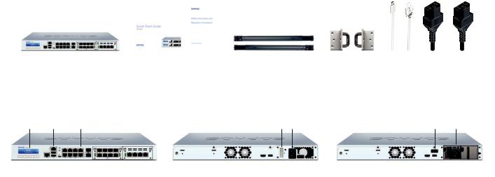
a) Verpackungsinhalt
|
|
|
|
|
|
Micro USB-Kabel |
|
|
|
|
|
|
|
|
|
|
|
|
|
|
|
|
|
|
|
|
|
XG 430/450 |
Diese Kurzanleitung und |
2 Rackmontage-Schienen |
2 Rackmontage- |
RJ45 Ethernet-Kabel |
||
(1U Rackmontage-Gehäuse) |
Sicherheitshinweise |
|
Halterungen |
2 Netzkabel |
||
|
|
|
|
|
|
|
b) Abbildungen der Appliance*: Vorderund Rückseite
XG 430/450 Rev. 2 |
XG 430 Rev. 2 |
|
|
XG 450 Rev. 2 |
|
|
Multifunktions- |
1 x COM |
8 x 10/100/1000 |
Anschluss für redundante |
|
|
|
LCD-Anzeige |
(RJ45) |
Base-TX-Ports |
externe Stromversorgung |
Netzteil |
Netzschalter |
Netzteil |
|
|
|
|
|
|
|
|
|
|
|
|
|
|
|
|
|
|
|
|
|
|
|
|
|
|
|
|
|
|
|
|
|
|
|
|
Navigation |
|
|
Micro USB |
2 x |
2 weitere |
1 x HDMI |
|
|
Netzschalter |
1 x HDMI |
|
|
Optionales |
||||
für LCD |
|
2 x |
SFP+ |
Erweiterungsschächte |
|
1 x |
|
|
|
1 x |
Netzteil |
||||||
|
|
|
USB 3.0 |
Ports |
(hier mit optionalem FleXi |
USB 3.0 |
|
|
USB 3.0 |
|
|
||||||
1 x Verwaltungsport |
|
Port-Modul abgebildet) |
|
|
|
|
|
|
|
|
|
|
|||||
|
|
(IPMI) |
|
|
|
|
|
|
|
|
|
|
|
|
|||
* Die Abbildung der Vorderseite bezieht sich auf die XG 450 Appliance. Die Abbildung für die XG 430 Appliance kann geringfügig abweichen.
Kurzanleitung XG 430/450 Rev. 2 |
7 |
 Loading...