


Quick Start Guide
SG 310/330 Rev. 2
Before you begin please confirm that you have a working Internet connection and make sure you have the account information available that was provided by your ISP.
1. Before Deploying
Congratulations on your purchase of the Sophos SG appliance to protect your data networks and computers. This Quick Start Guide describes in short steps how
to assemble the appliance and explains how to open the web-based WebAdmin configuration tool on the security system from your administration client PC. WebAdmin allows you to configure every aspect of the security system.
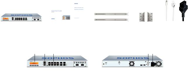
a) What does the box include
|
|
|
|
|
|
Micro USB cable |
|
|
|
|
|
|
|
|
|
|
|
|
|
|
|
|
|
|
|
|
|
SG 310/330 |
This Quick Start Guide and |
2 rack mount rails |
2 rack |
RJ45 Ethernet cable |
||
(1U rack mount chassis) |
Security Notes |
|
mount brackets |
1 power cable |
||
|
|
|
|
|
|
|
b) Device Images*: Front and Back
SG 310/330 Rev. 2
Multi-function |
1 x COM |
8 x GbE copper – fixed. Incl. 2 |
Connector for redundant |
Power |
LCD display |
(RJ45) |
bypass pairs (ports E0/1 and E2/3) |
external power supply |
supply |
|
|
|
|
|
|
|
|
|
|
|
|
|
|
|
|
|
|
|
|
|
|
|
|
|
|
|
|
|
|
Navigation |
|
Micro USB |
2 x |
2 x |
1 further expansion |
1 x HDMI |
|
|
Power |
switch |
||||
for LCD |
2 x |
SFP |
SFP+ |
bays (shown here |
|
1 x |
|
|
||||||
|
|
USB 3.0 |
ports |
ports |
with optional FleXi |
USB 3.0 |
|
|
||||||
|
|
|
|
|
|
|
|
Port module) |
|
|
|
|
|
|
* The displayed images are of SG 330 device. The SG 310 device may vary slightly.
Quick Start Guide SG 310/330 Rev. 2 |
1 |
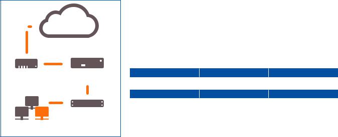
Internet
|
|
|
|
|
|
E1/any port |
|
|
|
|
|
|
|
|
|
|
|
|
|
|
|
|
|
|
|
|
|
||
|
|
|
|
|
|
|
|
|
|
|
|
|
|
|
|
|
|
|
|
||||||||||
|
|
|
|
|
|
|
|
|
|
|
|
|
|
|
|
|
|
|
|
|
|
||||||||
|
|
|
|
|
|
|
|
|
|
|
|
|
|
|
|
|
|
||||||||||||
|
|
|
|
|
|
|
|
|
|
|
|
|
|
|
|
|
|
|
|
||||||||||
e.g., |
UTM Appliance |
||||||||||||||||||||||||||||
DSL modem |
|
|
|
|
|
|
|
|
|
|
|
|
|
|
|
|
|
E0/ |
|||||||||||
|
|
|
|
|
|
|
|
|
|
|
|
|
|
|
|
|
|
|
|
|
|
|
|
|
|
||||
|
|
|
|
|
|
|
|
|
|
|
|
|
|
|
|
|
|
|
|
|
|
|
|
|
|
LAN |
|||
|
|
|
|
|
|
|
|
|
|
|
|
|
|
|
|
|
|
|
|
|
|
|
|
|
|
|
|
|
|
|
|
|
|
|
|
|
|
|
|
|
|
|
|
|
|
|
|
|
|
|
|
|
|
|
|
|
|
|
|
|
|
|
|
|
|
|
|
|
|
|
|
|
|
|
|
|
|
|
|
|
|
|
|
|
|
|
|
|
|
|
|
|
|
|
|
|
|
|
|
|
|
|
|
|
|
|
|
|
|
|
|
|
|
|
|
|
|
|
|
|
|
|
|
|
|
|
|
|
|
|
|
|
|
|
|
|
|
|
|
|
|
|
|
|
|
|
|
|
|
|
|
|
|
|
|
|
|
|
|
|
|
|
|
|
|
|
|
|
|
|
|
|
|
|
|
|
|
|
|
|
|
|
|
|
|
|
|
|
|
|
|
|
|
Switch |
|||||||||||||||
|
|
|
|
|
|
|
|
|
|
|
|
|
|
||||||||||||||||
|
|
|
|
|
|
|
|
|
|
|
|
|
|
||||||||||||||||
|
|
|
|
|
|
|
|
|
|
|
|
|
|
||||||||||||||||
|
|
|
|
|
|
|
|
|
|
|
|
|
|
|
|
|
|
|
|
|
|
|
|
|
|
|
|
|
|
Internal network |
|
|
|
|
|
|
|
|
|
|
|
|
|
|
|
|
|
|
|
|
|
||||||||
admin client PC |
|
|
|
|
|
|
|
|
|
|
|
|
|
|
|
|
|
|
|
|
|
||||||||
License
The security appliances are delivered with a 30-day trial version. During or after the trial period, you can activate the full license you purchased from your Sophos
partner by creating an account at https://myutm.sophos.com, activating the provided activation and upgrade keys, and uploading the created license file into your appliance.
2. Mount and connect the device
Connect the ports to the internal and external networks
1.Connect the E0/LAN port via a hub or switch to the internal network. For this purpose, please use the RJ45 Ethernet cable of the scope of supply. Note that your administration client PC must also be connected to this network.
2.Connect the E1/WAN port to the external network. The connection to the WAN depends on the type of Internet access.
The UTM appliances are shipped with the following default settings:
Ethernet Port |
|
IP Address |
|
Zone |
E0/LAN |
|
|
|
LAN |
192.168.0.1/255.255.255.0 |
|
|||
Default Gateway |
|
DNS Proxy |
|
DHCP Service |
None |
|
Enabled |
|
Disabled |
|
|
|||
Quick Start Guide SG 310/330 Rev. 2 |
2 |
Workstation connection properties:
IP address: Any address in the range 192.168.0.2 through 192.168.0.254
Netmask: Enter 255.255.255.0
Standard gateway: Enter the IP address of the appliance’s internal network card E0/LAN: 192.168.0.1
DNS server: Enable this option and enter the IP address of the internal network card E0/LAN: 192.168.0.1
Mount the appliance to the rack
Please follow the rack mounting instructions as described in the UTM Operating Instructions.*
3. Power Up the Device
Connect the power cable and turn on the device
Connect the device to the power supply using the power cable(s). Turn the device on. The power switch is on the back of the device and is placed next to the power connection. Once the device has booted completely, you’ll hear an acoustic signal: five beeps in a row.
4. Configure the device
Use your browser to make the initial connection to the WebAdmin GUI
You will need to configure a workstation with the necessary LAN properties to access WebAdmin. You can change these settings later to match your existing network. The location of the menu for these settings depends on the operating system of your client.
Example: With Windows 7, the menu can be found under Start >> Control Panel >> Network and Sharing Center
Start the browser and enter the management IP address of the appliance: https://192.168.0.1:4444
Accept the security notice by clicking OK (Mozilla Firefox) or Yes (MS Internet Explorer).
For configuration you can follow the initial setup wizard described in the WebAdmin Quick Start Guide** or cancel it and perform a manual setup (see the UTM Administration Guide*).
*Available at www.sophos.com/en-us/support/documentation/sophos-utm
**Available via WebAdmin >> Support >> Manual
Quick Start Guide SG 310/330 Rev. 2 |
3 |

5. Device LED Status
Power (LED Display)
Power Supply Acitve |
Green |
Power Supply Failure |
Red |
SSD Active |
Blue |
|
|
LEDs on each RJ45 Ethernet connector
ACT/LNK |
Green |
Constantly |
1. The Ethernet port is receiving power. |
(Left LED) |
|
|
2. Good connection between the Ethernet port and hub. |
|
|
Flashing |
The adapter is sending or receiving network data. The |
|
|
|
frequency of the flashes varies with the amount of traffic. |
|
|
Off |
1. The adapter and switch are not receiving power. |
|
|
|
2. No connection between both ends of network. |
|
|
|
3. Network drivers have not been loaded |
|
|
|
or do not function correctly. |
|
|
|
|
Speed |
Amber |
On |
The Ethernet port is operating at 1,000 Mbps. |
(Right LED) |
Green |
On |
The Ethernet port is operating at 100 Mbps. |
|
|
Off |
The Ethernet port is operating at 10 Mbps. |
|
|
||
LEDs on each SFP connector |
|
||
ACT/LNK |
Green |
Constantly |
1. The SFP connector is receiving power. |
|
|
|
2. Good linkage between the SFP connector and hub. |
|
|
Flashing |
The adapter is sending or receiving network data. The |
|
|
|
frequency of the flashes varies with the amount of traffic. |
|
|
Off |
1. The adapter and switch are not receiving power. |
|
|
|
2. No connection between both ends of network. |
|
|
|
3. Network drivers have not been loaded |
|
|
|
or do not function correctly. |
|
|
|
|
Quick Start Guide SG 310/330 Rev. 2 |
4 |

LEDs on each SFP+ connector
ACT/LINK |
|
Green |
|
Constantly |
1. The SFP+ connector is receiving power. |
|
(Left LED) |
|
|
|
|
|
2. Good linkage between the SFP+ connector and hub. |
|
|
|
|
|
Flashing |
The adapter is sending or receiving network data. The |
|
|
|
|
|
|
frequency of the flashes varies with the amount of traffic. |
|
|
|
|
|
Off |
1. The adapter and switch are not receiving power. |
|
|
|
|
|
|
2. No connection between both ends of network. |
|
|
|
|
|
|
3. Network drivers have not been loaded |
|
|
|
|
|
|
or do not function correctly. |
ACT/LINK |
|
Blue |
|
On |
The SFP+ connector is operating at 10,000 Mbps. |
|
(Right LED) |
|
Amber |
|
On |
The SFP+ connector is operating at 1,000 Mbps. |
|
|
|
|
|
|
Off |
Either the LED is not working or the SFP+ connector |
|
|
|
|
|
|
is operating at a speed below 1,000 Mbps. |
|
|
|
||||
LAN Bypass (LED Display) |
|
|||||
LAN Bypass Active |
|
Green |
|
|||
LAN Bypass Off |
|
|
Off |
|
||
|
|
|
|
|
|
|
Back side |
|
|
|
|
|
|
Power Supply |
|
Green |
|
Constantly |
Power |
|
|
|
|
|
|
Off |
No power |
|
|
|
|
|
|
|
6. Support and Documentation
For more information and technical support, please visit www.sophos.com/en-us/ support or contact your local Sophos reseller.
Quick Start Guide SG 310/330 Rev. 2 |
5 |
Bevor Sie beginnen, vergewissern Sie sich, dass Sie mit dem Internet verbunden sind und die Kontodaten vorliegen, die Sie von Ihrem ISP erhalten haben.
1. Vorbereitung
Herzlichen Glückwunsch zum Kauf dieser Sophos SG Appliance zum Schutz Ihrer Datennetzwerke und Computer. Diese Kurzanleitung beschreibt schrittweise die Montage der Appliance und erläutert, wie Sie über Ihren Administrations-Client-PC das webbasierte WebAdmin Konfigurationstool auf dem Sicherheitssystem öffnen. Mit WebAdmin können Sie jeden Aspekt des Sicherheitssystems konfigurieren.
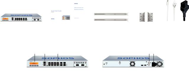
a) Verpackungsinhalt
|
|
|
|
|
|
Micro USB-Kabel |
|
|
|
|
|
|
|
|
|
|
|
|
|
|
|
|
|
|
|
|
|
SG 310/330 |
Diese Kurzanleitung und |
2 Rackmontage-Schienen |
2 Rackmontage- |
RJ45 Ethernet-Kabel |
||
(1U Rackmontage-Gehäuse) |
Sicherheitshinweise |
|
Halterungen |
1 Netzkabel |
||
|
|
|
|
|
|
|
b) Abbildungen der Appliance*: Vorderund Rückseite
SG 310/330 Rev. 2
Multifunktions- |
1 x COM |
8 GbE Kupfer - fest. Einschl. 2 Bypass- |
Anschluss für redundante |
|
LCD-Anzeige |
(RJ45) |
Paaren (Ports E0/1 und E2/3) |
externe Stromversorgung |
Netzteil |
|
|
|
|
|
|
|
|
|
|
|
|
|
|
|
|
|
|
|
|
|
|
|
|
|
|
|
|
|
|
Navigation |
|
Micro USB |
2 x |
2 x |
1 weiterer |
1 x HDMI |
|
Netzschalter |
||||||
für LCD |
2 x |
SFP- |
SFP+ |
Erweiterungsschacht |
|
1 x |
|
|
||||||
|
|
USB 3.0 |
Ports |
Ports |
(hier mit optionalem |
USB 3.0 |
|
|
||||||
|
|
|
|
|
|
|
|
FleXi Port-Modul |
|
|
|
|
|
|
|
|
|
|
|
|
|
|
abgebildet) |
|
|
|
|
|
|
* Die Abbildungen beziehen sich auf die SG 330 Appliance. Die Abbildung für die SG 310 Appliance kann geringfügig abweichen.
Kurzanleitung SG 310/330 Rev. 2 |
6 |
 Loading...