


Quick Start Guide
XG 105(w)/115(w)/125(w)/135(w) Rev. 3

For more information about your device, scan the QR code or visit
www.sophos.com/get-started-xg
1. Before Deploying
Congratulations on the purchase of your Sophos XG device. This Quick Start Guide describes in short steps how to connect your device and explains how to open the web-based Admin Console from your administration PC. The Admin Console allows you to configure every aspect of the device.
Before you begin please confirm that you have a working Internet connection and make sure you have the account information available that was provided by your ISP.
What is included in the box
XG 105(w)/115(w)/125(w)/135(w) |
This Quick Start Guide and Security Notes |
Micro USB cable |
|
|
RJ45 Ethernet cable |
XG 105w/115w - 2 antennas; |
Power Adapter (region specific) |
XG 125w/135w - 3 antennas |
|
1 |
Quick Start Guide XG 105(w)/115(w)/125(w)/135(w) Rev. 3 |
|

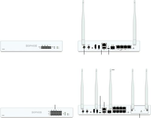
Device Images: Front and Back*
XG 105(w)/115(w)
Status LEDs
(w-model has additional Wi-Fi LED)
XG 125(w)/135(w)
Status LEDs
(w-model has additional Wi-Fi LED)
2 x external antenna (XG 105w and XG 115w only)
Connector for optional 2nd redundant power supply
1 x |
1 x COM |
1 x GbE SFP |
4 x GbE |
HDMI |
(RJ45) |
(shared) |
copper port |
Power |
2 x |
1 x Micro |
Supply |
USB 2.0 |
USB |
3 x external antenna
(XG 125w and XG 135w only)
1 x Micro USB
1 x COM (RJ45)
Power |
1 x |
2 x |
1 x GbE |
8 x GbE |
Expansion bay |
Supply |
HDMI |
USB 2.0 |
SFP |
copper port |
(shown with optional |
module incl. 2 antennas)
* The displayed front image is of the XG 115 and XG 135 device and the back is of the XG 115w and XG 135w.
Quick Start Guide XG 105(w)/115(w)/125(w)/135(w) Rev. 3 |
2 |
|

|
Internet |
||||
|
Port 2/ |
||||
|
WAN |
||||
|
|
|
|
|
|
|
|
|
|
||
|
|
|
|
||
e.g., |
XG Appliance |
||||
DSL modem
Port 1/
LAN
Switch
Internal network admin client PC
2. Mount & connect the device
Mount the antennas (for wireless models only)
Connect the provided antennas to the connectors on the back of your appliance and align them in a vertical position.
Connect the ports to the internal and external networks
1.Connect the Port 1/LAN port via a hub or switch to the internal network. For this purpose, use the RJ45 Ethernet cable provided. Note that your Administration PC must also be connected to this network.
2.Connect Port 2/WAN to the external network. The connection to the WAN depends on the type of Internet access.
Please note: on XG 105(w)/115(w) the SFP port is shared with RJ45 Ethernet Port 4 and takes precendence over the RJ45 port in case you connect cables to both ports at the same time.
The XG devices are shipped with the following default settings:
Ethernet Port |
IP Address |
|
|
Zone |
|
1 |
|
|
|
|
LAN |
172.16.16.16/255.255.255.0 |
|
|
|||
2 |
DHCP |
|
|
WAN |
|
Admin Console Username Admin Console Password |
|
CLI Console Password |
|||
admin |
|
admin |
|
admin |
|
|
|
||||
Default Gateway |
|
DNS proxy |
|
DHCP service |
|
DHCP |
|
Enabled |
|
Enabled |
|
|
|
||||
Mount the appliance to the rack
If you want to mount the device within a rack please use the optionally available rackmount kit for this device.
3 |
Quick Start Guide XG 105(w)/115(w)/125(w)/135(w) Rev. 3 |
|
3. Power Up the Device
Connect the power adapter(s) and turn on the device
Connect the provided power adapter to connector 1 on the back of the device. In order to increase redundancy you can connect an optionally available second power adapter of the same type to power connector 2.
Turn the device on. The power switch is on the back of the device and is placed next to the power connection.
During boot up the Status LED on the front will blink green. Once the device has booted completely the Status LED will turn to solid green.
4. Connect your Administration PC
Administration PC connection properties:
Use the settings below to configure your (PC/Laptop) network interface:
ÌÌ IP address: 172.16.16.2
ÌÌ Netmask: Enter 255.255.255.0
ÌÌ Default Gateway: Enter the IP address of the device’s internal network card (Port 1/LAN): 172.16.16.16
ÌÌ DNS Server: Enable this option and enter the IP address of the internal network card (Port 1/LAN): 172.16.16.16
Connect your PC/Laptop to Port 1/LAN port of the device:
Start the browser and enter the management IP address of the device’s LAN port that your PC is connected to: https://172.16.16.16:4444 (Port 1)
Login with the default details below:
Username: admin Password: admin
Quick Start Guide XG 105(w)/115(w)/125(w)/135(w) Rev. 3 |
4 |
|

Device Management
Welcome
To your Sophos Device
To get started register your device below. Until you register you may only access and edit settings in “Basic Setup” and your device will remain unactivated.
Serial Number |
XXXXXXXXXXXXXXX |
Basic Setup
Register Device
Network Configuration Wizard
Secure your enterprise with
Sophos integrated internet security
Skip Start
5. Setup the device a) Register the Device
If you have not previously registered your device with your Sophos ID, you will see a registration screen. The device requires Internet connectivity for it to be registered with your Sophos ID. You can adjust the network settings of the device’s interfaces by clicking “Basic Setup” so that the device can connect to the Internet.
After clicking “Register Device”, you are redirected to the Sophos.com. If you already have a Sophos ID, enter your login credentials under “Sign in with your Sophos ID”. If you are a new user, sign up for a Sophos ID by entering the details under “Create Sophos ID”.
Click “Continue” to complete the registration process. Please wait while the process completes – it will take a few seconds. After successful registration, you will see
a screen with the message, “Your device is now registered”. Please note that you should proceed with the next step i.e. “Synchronize License” only after the device is successfully registered.
b) Synchronize License
Click “Initiate License Synchronization” to fetch license information from Sophos onto the device. After synchronization, you will see a screen with the message, “Synchronization with server was successful”.
c) Start Network Configuration
After successful synchronization, choose “Click Here” on the “Welcome” screen to start your initial device configuration. Use the Network Configuration Wizard to select the deployment mode (Bridge/Gateway) for your device, change the interface(s) IP addresses, default gateway, DNS settings and Date/Time Zone to match your local network settings.
d) Device LED Status
LEDs on each RJ45 Ethernet connector
ACT/LNK |
Green |
Constantly |
1. The Ethernet port is receiving power. |
(Left LED) |
|
|
2. Good connection between the Ethernet port |
|
|
|
and hub. |
|
|
Flashing |
The adapter is sending or receiving network data. |
|
|
|
The frequency of the flashes varies with the |
|
|
|
amount of traffic. |
|
|
Off |
1. The adapter and switch are not receiving power. |
|
|
|
2. No connection between both ends of network. |
|
|
|
3. Network drivers have not been loaded or do not |
|
|
|
function correctly. |
|
|
|
|
5 |
Quick Start Guide XG 105(w)/115(w)/125(w)/135(w) Rev. 3 |
|
Speed |
Amber |
On |
The Ethernet port is operating at 1,000 Mbps |
|
(Right |
Green |
On |
The Ethernet port is operating at 100 Mbps |
|
LED) |
||||
|
Off |
The Ethernet port is operating at 10 Mbps |
||
|
|
|||
|
|
|
||
LEDs on SFP connector |
|
|||
ACT/LNK |
Green |
Constantly |
1. The SFP connector is receiving power. |
|
(Left LED) |
|
|
2. Good connection between the SFP connector |
|
|
|
|
and hub. |
|
|
|
Flashing |
The adapter is sending or receiving network data. |
|
|
|
|
The frequency of the flashes varies with the amount |
|
|
|
|
of traffic. |
|
|
|
Off |
1. The adapter and switch are not receiving power. |
|
|
|
|
2. No connection between both ends of network. |
|
|
|
|
3. Network drivers have not been loaded or do not |
|
|
|
|
function correctly. |
|
|
|
|
|
|
Speed |
Amber |
On |
The Ethernet port is operating at 1,000 Mbps |
|
(Right |
|
|
|
|
LED) |
|
|
|
|
|
|
|
||
LEDs on front |
|
|
||
Storage |
Blue |
Flashing |
SSD drive is being accessed |
|
Status |
Green |
Constantly |
Normal operation |
|
|
|
Flashing |
Device is booting up or shutting down |
|
|
|
|
|
|
|
Red |
Constantly |
SSD or boot failure |
|
|
|
Flashing |
General error (please contat support) |
|
Wifi |
Green |
On |
Wifi is active |
|
|
|
|
|
|
|
|
Off |
Wifi is inactive |
|
Power 1 |
Green |
Constantly |
Power adapter 1 in normal operation |
|
|
|
|
|
|
|
Red |
Constantly |
Power adapter 1 failed or disconnected |
|
Power 2 |
Green |
Constantly |
Power adapter 2 in normal operation |
|
|
|
|
|
|
|
Red |
Constantly |
Power adapter 2 failed or disconnected |
|
6. Support and Documentation
For more information and technical support, please visit www.sophos.com/en-us/ support or contact your local Sophos reseller.
Quick Start Guide XG 105(w)/115(w)/125(w)/135(w) Rev. 3 |
6 |
|

Für weitere Informationen zu Ihrer Appliance scannen Sie den QR-Code oder gehen Sie auf
www.sophos.com/get-started-xg
1. Vorbereitung
Herzlichen Glückwunsch zum Kauf dieser Sophos XG Appliance. Diese Kurzanleitung beschreibt schrittweise, wie Sie die Appliance verbinden, und erläutert, wie Sie über Ihren Administrations-PC die webbasierte Admin Console öffnen. Über die Admin Console können Sie jeden Aspekt der Appliance konfigurieren.
Bevor Sie beginnen, vergewissern Sie sich, dass Sie mit dem Internet verbunden sind und die Kontodaten vorliegen, die Sie von Ihrem ISP erhalten haben.
Verpackungsinhalt
XG 105(w)/115(w)/125(w)/135(w) |
Diese Kurzanleitung und Sicherheitshinweise |
Micro USB-Kabel |
|
|
RJ45 Ethernet-Kabel |
XG 105w/115w – 2 Antennen, |
Netzadapter (regionenspezifisch) |
XG 125w/135w – 3 Antennen |
|
7 |
Kurzanleitung XG 105(w)/115(w)/125(w)/135(w) Rev. 3 |
|
Abbildungen der Appliance: Vorderund Rückseite*
XG 105(w)/115(w) Rev. 3
2 x externe Antenne (nur XG 105w und XG 115w)
|
|
Anschluss für optionale |
|
|
||||
|
|
zweite redundante |
|
|
|
|
||
|
|
Stromversorgung |
1 x GbE |
4 x |
||||
Status-LEDs |
1 x 1 x COM |
SFP |
Kupferport |
|||||
(w-Modell hat zusätzliche WiFi-LED) |
HDMI (RJ45) |
(geteilt) |
GbE |
|||||
|
|
|
|
|
|
|
|
|
|
|
|
|
|
|
|
|
|
|
|
|
|
|
|
|
|
|
XG 125(w)/135(w) Rev. 3
Status-LEDs
(w-Modell hat zusätzliche WiFi-LED)
Stromversorgung |
2 x |
1 x Micro- |
|
USB 2.0 |
USB |
3 x externe Antenne (nur XG 125w
und XG 135w)
1 x MicroUSB
1 x COM (RJ45)
|
|
|
|
|
|
|
|
|
|
|
|
|
|
|
|
|
|
|
|
|
|
|
|
|
|
1 x |
2 x |
1 x GbE |
8 x |
||||||
|
|
HDMI |
USB 2.0 |
SFP |
Kupferport |
||||||
|
|
Anschluss für optionale |
GbE |
||||||||
|
|
|
|
||||||||
|
|
zweite redundante |
|
|
|
|
|||||
|
|
Stromversorgung |
|
|
|
|
|||||
Stromversorgung |
|
|
|
|
|
|
|
|
|||
* Die Abbildung der Vorderseite bezieht sich auf die XG 115 und XG 135 Appliance und die der Rückseite auf die XG 115w und XG 135w.
Erweiterungsschacht (abgebildet mit optionalem Modul einschl. 2 Antennen)
Kurzanleitung XG 105(w)/115(w)/125(w)/135(w) Rev. 3 |
8 |
|

|
Internet |
||||
|
Port 2/ |
||||
|
WAN |
||||
|
|
|
|
|
|
|
|
|
|
||
|
|
|
|
||
z. B. |
XG Appliance |
||||
DSL-Modem
Port 1/
LAN
Switch
Internes
Netzwerk
Administrations-
Client-PC
2. Appliance montieren und verbinden
Antennen montieren (nur bei Wireless-Modellen)
Stecken Sie die mitgelieferten Antennen in die entsprechenden Anschlüsse auf der Rückseite Ihrer Appliance ein und bringen Sie sie in eine vertikale Position.
Ports mit den internen und externen Netzwerken verbinden
1.Verbinden Sie Port 1/LAN-Port über einen Hub oder Switch mit dem internen Netzwerk. Verwenden Sie hierzu das beiliegende RJ45 Ethernet-Kabel. Beachten Sie, dass Ihr Administrations-PC ebenfalls mit diesem Netzwerk verbunden sein muss.
2.Verbinden Sie Port 2/WAN mit dem externen Netzwerk. Die Verbindung zum WAN hängt von der Art des Internetzugangs ab.
Bitte beachten Sie: Bei XG 105(w)/115(w) wird der SFP-Port mit RJ45 EthernetPort 4 geteilt und hat Vorrang vor dem RJ45-Port für den Fall, dass Sie Kabel mit beiden Ports gleichzeitig verbinden.
Für die XG Appliances sind werkseitig folgende
Standardeinstellungen festgelegt:
|
|
|
|
|
Vertrauenswürdige |
Ethernet-Port |
IP-Adresse |
|
Sites |
||
1 |
|
172.16.16.16/255.255.255.0 |
|
LAN |
|
|
|
||||
2 |
|
|
DHCP |
|
WAN |
Benutzername Admin |
|
Kennwort Admin Console |
Kennwort CLI Console |
||
Console |
|
|
|
|
|
admin |
|
admin |
|
admin |
|
|
|
||||
Standard-Gateway |
|
DNS-Proxy |
DHCP-Dienst |
||
DHCP |
|
Aktiviert |
|
Aktiviert |
|
|
|
||||
|
|
|
|
|
|
Appliance im Rack montieren
Wenn Sie die Appliance in einem Rack montieren möchten, verwenden Sie das für dieses Gerät optional erhältliche Rackmontage-Kit.
9 |
Kurzanleitung XG 105(w)/115(w)/125(w)/135(w) Rev. 3 |
|
 Loading...