

Sony XRCA-440-X Service manual
XR-CA440/CA440X
SERVICE MANUAL
Ver 1.1 2003.01
Photo: XR-CA440
SPECIFICATIONS
Cassette Player section
Tape track 4-track 2-channel stereo
Wow and flutter 0.08 % (WRMS)
Frequency response 30 – 18,000 Hz
Signal-to-noise ratio
Tuner section
FM
Tuning range FM tuning interval:
(XR-CA440X: AEP ,
UK, Saudi Arabia
and Taiw an models)
T
uning range FM tuning interval:
(XR-CA440/
CA440X: E models)
Aerial terminal External aerial connector
Intermediate frequency 10.7 MHz
Usable sensitivity 11 dBf
Selectivity 75 dB at 400 kHz
Signal-to-noise ratio 65 dB (stereo),
Harmonic distortion at 1 kHz
Separation 33 dB at 1 kHz
Frequency response 30 – 15,000 Hz
AM
(XR-CA440X: AEP and UK models)
Tuning range AM tuning interval:
Sensitivity 30 µV
Aerial terminal External aerial connector
Intermediate frequency 10.7 MHz/450 kHz
Cassette type
TYPE II, IV 61 dB
TYPE I 58 dB
87.5 – 108.0 MHz
50 kHz/200 kHz switchable
87.5 – 108.0 MHz
(at 50 kHz step)
87.5 – 107.9 MHz
(at 200 kHz step)
68 dB (mono)
0.7 % (stereo),
0.5 % (mono)
531 – 1,602 kHz
MW
(XR-CA440/CA440X: E, Saudi Arabia
and Taiwan models)
T
uning range MW tuning interval:
(XR-CA440/
CA440X: E Models)
Tuning range
(XR-CA440X:
Saudi Arabia
and Taiwan models)
Se
nsitivity 30 µV
SW
(XR-CA440/CA440X: E, Saudi Arabia
and Taiwan models)
Tuning range SW tuning interval:
Aerial terminal External aerial connector
Intermediate frequency 10.7 MHz/450 kHz
Sensitivity 30 µV
9 kHz/10 kHz switchable
531 – 1,602 kHz
(at 9 kHz step)
530 – 1,710 kHz
(a
NW tuning interval:
531 – 1,602 kHz
SW1: 2,940 – 7,735 kHz
SW2: 9,500 – 18,135 kHz
(except for 10,140 – 11,575
kHz)
AEP Model
UK Model
XR-CA440X
E Model
XR-CA440/CA440X
Model Name Using Similar Mechanism NEW
Tape T r ansport Mechanism Type MG-25F-136
Power amplifier section
t 10 kHz step)
Outputs Speaker outputs
Speaker impedance 4 – 8 ohms
Maximum power output 50 W × 4 (at 4 ohms)
General
Outputs Audio outputs
Inputs BUS control input terminal
Tone controls Bass ±9 dB at 100 Hz
Power requirements 12 V DC car battery
Dimensions Approx. 178 × 50 × 178
Mounting dimensions Approx. 182 × 53 × 161
Mass Approx. 1.2 kg
Supplied accessories Parts for installation and
Note
This unit cannot be connected to a digital preamplifier
or an equalizer.
Design and specifications are subject to change
without notice.
(sure seal connectors)
Power aerial relay control
lead
Power amplifier control lead
BUS audio input terminal
Aerial input terminal
Treble ±9 dB at 10 kHz
(negative earth)
mm (w/h/d)
mm (w/h/d)
connections (1 set)
Front panel case (1)
XR-CA440X: AEP, UK Model
FM/AM CASSETTE CAR STEREO
XR-CA440/CA440X: E Model
9-873-497-02 Sony Corporation
2003A0500-1 e Vehicle Company
C 2003.01 Published by Sony Engineering Corporation
FM/MW/SW CASSETTE CAR STEREO

XR-CA440/CA440X
TABLE OF CONTENTS
1. GENERAL
Location of Controls ....................................................... 3
Setting the Clock ............................................................. 3
Installation /Connection .................................................. 4
2. DISASSEMBLY
2-1. Disassembly Flow ........................................................... 8
2-2. Cover ............................................................................... 8
2-3. Mechanism Deck (MG-25F-136) ................................... 9
2-4. MAIN Board ................................................................... 9
2-5. Heat Sink ......................................................................... 10
3. ASSEMBLY OF MECHANISM DECK
3-1. Assembly Flow................................................................ 11
3-2. Housing ........................................................................... 12
3-3. Arm (Suction) ................................................................. 12
3-4. Lever (LDG-A)/(LDG-B) ............................................... 13
3-5. Gear (LDG-FT) ............................................................... 13
3-6. Guide (C)......................................................................... 14
3-7. Mounting Position of Capstan/Reel Motor (M901)....... 14
4. MECHANICAL ADJUSTMENTS....................... 15
5. ELECTRICAL ADJUSTMENTS
Tape Deck Section .......................................................... 15
Tuner Section .................................................................. 15
Notes on chip component replacement
• Never reuse a disconnected chip component.
• Notice that the minus side of a tantalum capacitor may be dam-
aged by heat.
Flexible Circuit Board Repairing
• Keep the temperature of the soldering iron around 270 ˚C during repairing.
• Do not touch the soldering iron on the same conductor of the
circuit board (within 3 times).
• Be careful not to apply force on the conductor when soldering
or unsoldering.
6. DIAGRAMS
6-1. Note for Printed Wiring Boards and
Schematic Diagrams ....................................................... 15
6-2. Printed W iring Board – MAIN Board – ......................... 16
6-3. Schematic Diagram – MAIN Board (1/3) – ................... 17
6-4. Schematic Diagram – MAIN Board (2/3) – ................... 18
6-5. Schematic Diagram – MAIN Board (3/3) – ................... 19
6-6. Printed W iring Board – KEY Board –............................ 20
6-7. Schematic Diagram – KEY Board – .............................. 21
6-8. IC Pin Function Description ........................................... 24
7. EXPLODED VIEWS
7-1. Chassis Section ............................................................... 27
7-2. Front Panel Section ......................................................... 28
7-3. MAIN Board Section ...................................................... 29
7-4. Mechanism Deck Section (MG-25F-136) ...................... 30
8. ELECTRICAL PARTS LIST ............................... 31
2
SECTION 1
GENERAL
XR-CA440/CA440X
This section is extracted from
instruction manual.
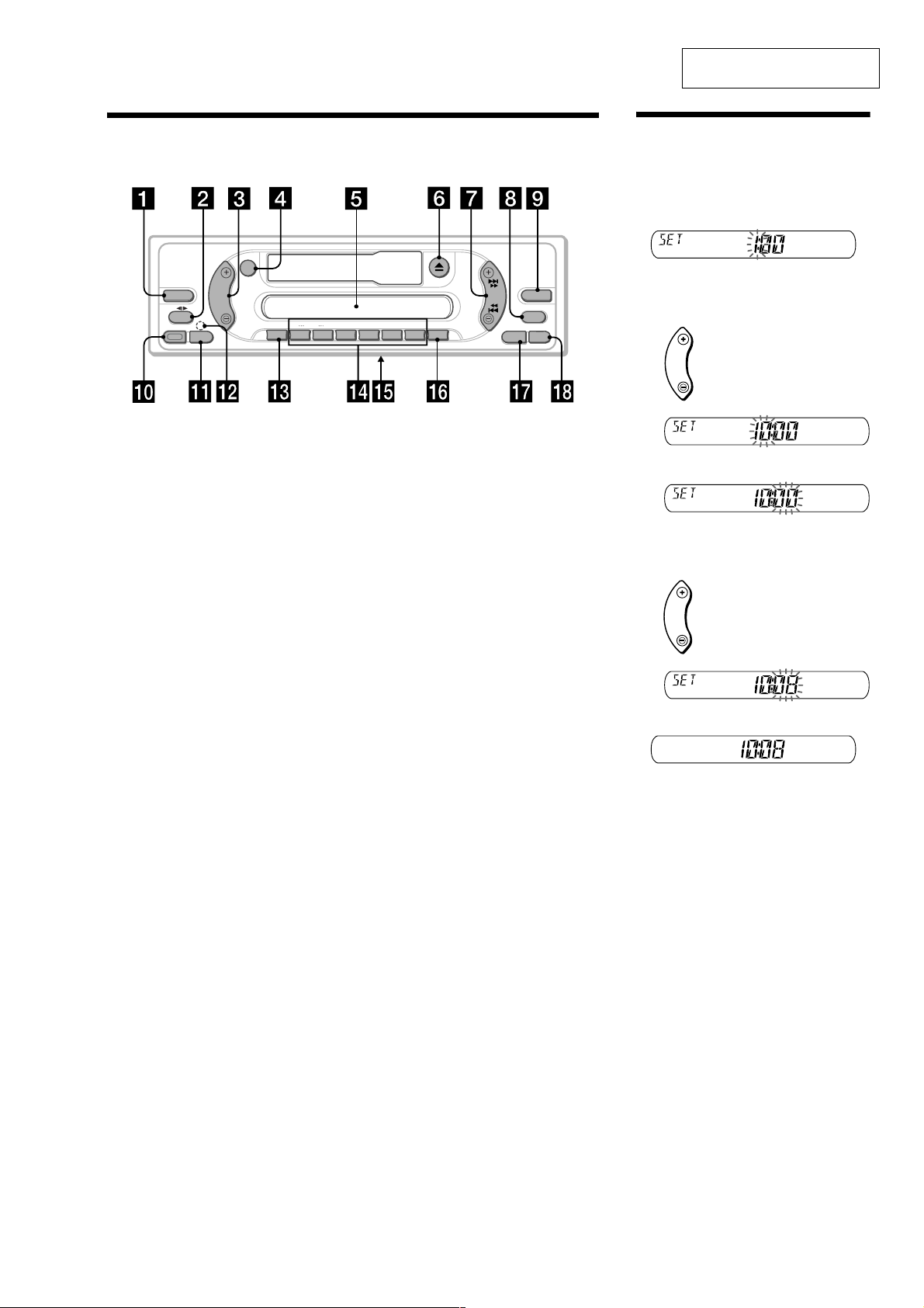
Location of controls
Refer to the pages listed for details.
ATT
MODE
SEL
VOL
+
DISC
–
12345 6
SENS
SOURCE
RELEASE
a SOURCE (Power on/Tape/Radio/CD/
MD) select button
b MODE (o) button
Selecting the source.
c VOL +/– button
d ATT (attenuate) button
e Display window
f Z (eject) button 8
g SEEK/AMS button
Ta pe :
Fast-forwarding, reversing a tape
Radio:
Tuning in stations automatically.
Finding a station manually.
CD (MP3 files)/MD:
Skipping tracks.
h MBP (My Best sound P osition) b utton
12
i D-BASS button 12
j RELEASE (front panel release) button
k SEL (select) button
Selecting items.
l RESET b utton (located on the front side of
the unit, behind the front panel) 6
m SENS button
Storing the stations with the strongest
signals.
SEEK
D-BASS
AMS
REP
SHUF BL
SKIP/ ALBM
-+/ATA
MTL
BTM
XR-CA440X
XR-CA440
MBP
OFFDSPL
n Number buttons
Ta pe :
(3): REP (Repeat)
(5): BL SKIP (Blank Skip)
(6): ATA (Automatic Tuner Activation)
Radio:
Storing the desired station on each number
button.
CD (MP3 files)/MD:
(1): DISC –
(2): DISC +
(3): REP (Repeat)
(4): SHUF (Shuffle)
MP3 files:
(5): ALBM –
(6): AL B M +
o Frequency select switch (located on
the
bottom of the unit)
(XR-CA440/CA440X: E models)
ee “Frequency select switch” in the
S
Installation/Connections manual.
p BTM/MTL (Best T uning Memory/Metal)
button 9
q DSPL (display mode change) button
r OFF (Stop/Power off) button*
* Warning when installing in a car without
an ACC (accessory) position on the
ignition switch
After turning off the ignition, be sure to press
(OFF) on the unit for 2 seconds to turn off
the clock display.
Otherwise, the clock display does not turn off
and this causes battery drain.
Setting the clock
The clock uses a 12-hour digital indication.
Example: To set the clock to 10:08
1
Press (DSPL) for 2 seconds.
The hour indication flashes.
1Press either side of (VOL) to set the
hour.
to go forward
VOL
to go back
2Press (SEL).
The minute indication flashes.
3Press either side of (VOL) to set the
minute.
to go forward
VOL
to go back
2
Press (DSPL).
The clock starts.
After the clock setting is completed, the
display returns to normal play mode.
3
XR-CA440/CA440X
Installation/Connection
2
A
B
AUDIO OUT REAR
BUS AUDIO IN
BUS CONTROL IN
Source selector*
Selector de fuente
BUS AUDIO IN
BUS CONTROL IN
* not supplied
no suministrado
Parts Iist (1)
The numbers in the list are keyed to those in the
instructions.
Caution
Handle the bracket 1 carefully to avoid injuring
your fingers.
1
Cautions
• This unit is designed for negative earth 12 V
DC operation only.
• Do not get the wires under a screw, or caught
in moving parts (e.g. seat railing).
• Before making connections, turn the car
ignition off to avoid short circuits.
• Connect the yellow and red power input leads
only after all other leads have been connected.
• Run all earth wires to a common earth
point.
• Be sure to insulate any loose unconnected
wires with electrical tape for safety.
Notes on the power supply cord (yellow)
• When connecting this unit in combination with
other stereo components, the connected car
circuit’s rating must be higher than the sum of
each component’s fuse.
• When no car circuits are rated high enough,
connect the unit directly to the battery.
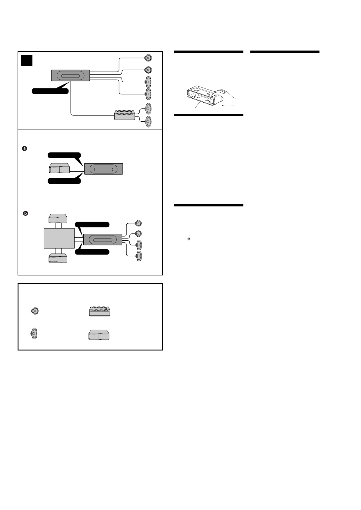
Connection example (2)
Notes (2-A)
• Be sure to connect the earth cord before
connecting the amplifier.
• If you connect an optional power amplifier and do
not use the built-in amplifier, the beep sound will
be deactivated.
Tip (2-B-
)
For connecting two or more CD/MD changers, the
source selector XA-C30 (optional) is necessary.
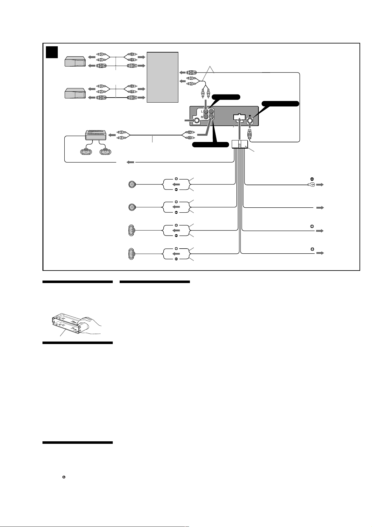
Connection diagram (3)
1 To a metal surface of the car
First connect the black earth lead, then connect
the yellow and red power input leads.
2 To the power aerial control lead or power
supply lead of aerial booster amplifier
Notes
• It is not necessary to connect this lead if there
is no power aerial or aerial booster, or with a
manually-operated telescopic aerial.
• When your car has a built-in FM/MW/SW aerial
in the rear/side glass, see “Notes on the control
and power supply leads.”
3 To AMP REMOTE IN of an optional power
amplifier
This connection is only for amplifiers. Connecting
any other system may damage the unit.
4 To the +12 V power terminal which is energised
in the accessory position of the ignition key
switch
Notes
• If there is no accessory position, connect to the
+12 V power (battery) terminal which is
energised at all times.
Be sure to connect the black earth lead to it
first.
• When your car has a built-in FM/MW/SW aerial
in the rear/side glass, see “Notes on the control
and power supply leads.”
5 To the +12 V power terminal which is energised
at all times
Be sure to connect the black earth lead to it first.
Notes on the control and power supply leads
• The power aerial control lead (blue) supplies +12 V
DC when you turn on the tuner.
• When your car has built-in FM/MW/SW aerial in
the rear/side glass, connect the power aerial
control lead (blue) or the accessory power input
lead (red) to the power terminal of the existing
aerial booster. For details, consult your dealer.
• A power aerial without relay box cannot be used
with this unit.
Memory hold connection
When the yellow power input lead is connected,
power will always be supplied to the memory circuit
even when the ignition key is turned off.
Notes on speaker connection
Before connecting the speakers, turn the unit off.
•
• Use speakers with an impedance of 4 to 8 ohms, and
with adequate power handling capacities to avoid its
damage.
• Do not connect the speaker terminals to the car
chassis, or connect the terminals of the right speakers
with those of the left speaker.
• Do not connect the earth lead of this unit to the
negative (–) terminal of the speaker.
• Do not attempt to connect the speakers in parallel.
• Connect only passive speakers. Connecting active
speakers (with built-in amplifiers) to the speaker
terminals may damage the unit.
• To avoid a malfunction, do not use the built-in speaker
wires installed in your car if the unit shares a common
negative (–) lead for the right and left speakers.
• Do not connect the unit’s speaker cords to each other.
Equipment used in illustrations (not supplied)
Equipo utilizado en las ilustraciones (no suministrado)
Front speaker
Altavoces delanteros
Rear speaker
Altavoces traseros
Power amplifier
Amplificador de potencia
CD/MD changer
Cambiador de CD/MD
4
XR-CA440/CA440X
3
Supplied with the CD/MD changer
Suministrado con el cambiador de CD/MD
RCA pin cord (not supplied)
Cable con clavijas RCA (no suministrado)
AMP REM
Max. supply current 0.3 A
Corriente máx. de alimentación de 0,3 A
Left
Izquierdo
Right
Derecho
Left
Izquierdo
Right
Derecho
3
Source selector
Selector de fuente
XA-C30
from car aerial
de antena de automóvil
Supplied with XA-C30
Suministrado con el XA-C30
BUS AUDIO IN
BUS
AUDIO
AUDIO IN
OUT
Fuse (10 A)
Fusible (10 A)
AUDIO OUT REAR
Blue/white striped
Con raya azul/blanca
White
Blanco
White/black striped
Con raya blanco/negro
Grey
Gris
Grey/black striped
Con raya gris/negro
Green
Verde
Green/black striped
Con raya verde/negro
Purple
Púrpura
Purple/black striped
Con raya púrpura/negro
Black
Negro
Blue
Azul
Red
Rojo
Yellow
Amarillo
BUS CONTROL IN
XR-CA440X
XR-CA440
7
Max. supply current 0.1 A
Corriente máx. de alimentación de 0,1 A
ANT REM
1
2
4
5
Lista de componentes (1)
Los números de la lista corresponden a los de las
instrucciones.
Precaución
Tenga mucho cuidado al manipular el soporte 1
para evitar posibles lesiones en los dedos.
1
Precauciones
• Esta unidad ha sido diseñada para alimentarse
con cc 12 V, negativo a masa, solamente.
• No coloque los cables debajo de ningún tornillo,
ni los aprisione con partes móviles (p.ej. los raíles
del asiento).
• Antes de realizar las conexiones, desactive el
encendido del automóvil para evitar
cortocircuitos.
• Conecte los cables de entrada de alimentación
amarillo y rojo solamente después de haber
conectado los demás.
• Conecte todos los conductores de puesta a
masa a un punto común.
• Por razones de seguridad, asegúrese de aislar con
cinta eléctrica los cables sueltos que no estén
conectados.
Notas sobre el cable de suministro de
alimentación (amarillo)
• Cuando conecte esta unidad en combinación con
otros componentes estéreo, la capacidad nominal
del circuito conectado del automóvil debe ser
superior a la suma del fusible de cada
componente.
• Si no hay circuitos del automóvil con capacidad
nominal suficientemente alta, conecte la unidad
directamente a la batería.
Ejemplo de conexiones (2)
Notas (2-A)
• Asegúrese de conectar primero el cable de puesta
a masa antes de realizar la conexión al
amplificador.
• Si conecta un amplificador de potencia opcional y
no utiliza el incorporado, los pitidos se
desactivarán.
Consejo (2-B-
Cuando desee conectar dos o más CD/MD cambiadores,
necesitará un selector de fuente XA-C30 (opcional).
)
Diagramas de conexión (3)
1 A una superficie metálica del automóvil
Conecte primero el cable de masa negro, y después los
cables amarillo y rojo de entrada de alimentación.para
obtener información detallada.
2 Al cable de control de la antena motorizada o al cable
de fuente de alimentación del amplificador de antena
Notas
•
Si no se dispone de antena motorizada ni de
amplificador de antena, o se utiliza una antena
telescópica accionada manualmente, no será
necesario conectar este cable.
•
Si el automóvil incorpora una antena de FM/MW/SW
en el cristal trasero/lateral, consulte “Notas sobre los
cables de control y de fuente de alimentación”.
3 Para conectar a AMP REMOTE IN del amplificador de
potencia opcional
Esta conexión es sólo para amplificadores.
La conexión de cualquier otra sistema puede dañar la
unidad.
4 Al terminal de alimentación de +12 V que recibe
energía en la posición de accesorios del interruptor de
la llave de encendido
Notas
•
Si no hay posición de accesorios, conéctelo al
terminal de alimentación (batería) de +12 V que
recibe energía sin interrupción.
Asegúrese de conectar primero el cable de masa
negro.
•
Si el automóvil incorpora una antena de FM/MW/SW
en el cristal trasero/lateral, consulte “Notas sobre los
cables de control y de fuente de alimentación”.
5 Al terminal de alimentación de +12 V que recibe
energía sin interrupción
Asegúrese de conectar primero el cable de masa
negro.
Notas sobre los cables de control y de fuente de
alimentación
El conductor de control de la antena motorizada (azul)
•
suministrará + cc 12 V cuando conecte la alimentación
del sintonizador.
•
Si el automóvil dispone de una antena de FM/MW/SW
incorporada en el cristal trasero/lateral, conecte el cable
de control de antena motorizada (azul) o el cable de
entrada de alimentación auxiliar (rojo) al terminal de
alimentación del amplificador de antena existente. Para
obtener información detallada, consulte a su proveedor.
•
Con esta unidad no es posible utilizar una antena
motorizada sin caja de relé.
Conexión para protección de la memoria
Si conecta el conductor de entrada amarillo, el circuito de
la memoria recibirá siempre alimentación, incluso aunque
ponga la llave de encendido en la posición OFF.
Notas sobre la conexión de los altavoces
•
Antes de conectar los altavoces, desconecte la
alimentación de la unidad.
•
Utilice altavoces con una impedancia de 4 a 8 ohmios, y
con la potencia máxima admisible adecuada, ya que de
lo contrario podría dañarlos.
•
No conecte los terminales del sistema de altavoces al
chasis del automóvil, ni los del altavoz izquierdo a los del
derecho.
•
No conecte el cable de puesta a tierra de esta unidad al
terminal negativo (–) del altavoz.
•
No intente conectar los altavoces en paralelo.
•
No conecte altavoces activos (con amplificadores
incorporados) a los terminales de altavoces de la unidad.
Si lo hiciese, podría dañar tales altavoces. Por lo tanto,
cerciórese de conectar altavoces pasivos a estos
terminales.
•
Para evitar fallos de funcionamiento, no utilice los cables
de altavoz incorporados instalados en el automóvil si su
unidad comparte un cable negativo común (–) para los
altavoces derecho e izquierdo.
•
No conecte los cables de altavoz de la unidad entre sí.
5
XR-CA440/CA440X
4 A
(RELEASE)
1
5
182 mm
53 mm
1
Precautions
•Choose the installation location carefully so
that the unit will not interfere with normal
driving operations.
•Avoid installing the unit in areas subject to
dust, dirt, excessive vibration, or high
temperatures, such as in direct sunlight or near
heater ducts.
•Use only the supplied mounting hardware for
a safe and secure installation.
Mounting angle adjustment
Adjust the mounting angle to less than 20°.
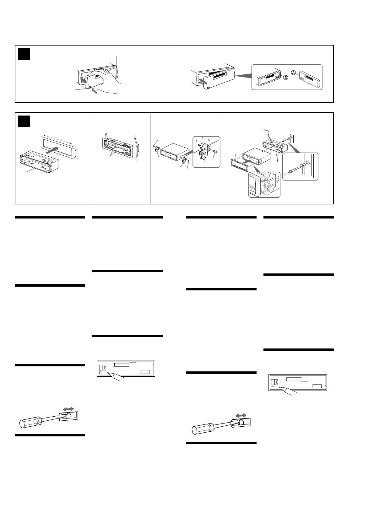
How to detach and attach the
front panel (4)
Before installing the unit, detach the front
panel.
4-A To detach
Before detaching the front panel, be sure to
press (OFF). Press (RELEASE), then slide the
front panel to the right side, and pull out the left
side.
4-B To attach
Attach part A of the front panel to part B of the
unit as illustrated and push the left side into
position until it clicks.
Frequency
(XR-CA440/CA440X: E models)
The MW (FM) tuning interval is factory-set to
the 10k (200 k) position. If the frequency
allocation system of your country is based on
9kHz (50 kHz) interval, set the switch on the
bottom of the unit to the 9k (50 k) position
before making connections.
select switch
(OFF)
2
Bend these claws outward
for a tight fit, if necessary.
Si es necesario, doble estas
uñas hacia fuera para que
encaje firmemente.
3
Mounting the unit in a Japanese
car (6)
You may not be able to install this unit in some
makes of Japanese cars. In such a case, consult
your Sony dealer.
Note
To prevent malfunction, install only with the
supplied screws 4.
Warning when installing in a car
without ACC (accessory)
position on the ignition key
switch
Be sure to press (OFF) on the unit for two
seconds to turn off the clock display after
turning off the engine.
When you press (OFF) only momentarily, the
clock display does not turn off and this causes
battery wear.
RESET button
When the installation and connections are
completed, be sure to press the RESET button
with a ballpoint pen, etc.
B
4
4
5
5
4
Precauciones
•Elija cuidadosamente el lugar de montaje de
forma que la unidad no interfiera las funciones
normales de conducción.
•Evite instalar la unidad donde pueda quedar
sometida a altas temperaturas, como a la luz
solar directa o al aire caliente de calefacción, o
a polvo, suciedad, o vibraciones excesivas.
•Para realizar una instalación segura y firme,
utilice solamente la ferretería de montaje
suministrada.
Ajuste del ángulo de montaje
Ajuste el ángulo de montaje a menos de 20°.
Forma de extraer e instalar el
panel frontal (4)
Antes de instalar la unidad, extraiga el panel
frontal.
4-A Para extraerlo
Antes de extraer el panel frontal, ceriórese de
presionar (OFF). Después presione (RELEASE)
a fin de abrirlo, después deslícelo hacia la
derecha, y por último tire de su parte izquierda.
4-B Para instalarlo
Coloque el orificio A del panel frontal en el eje
B de la unidad, como se muestra en la
ilustración, y después presione la parte
izquierda.
Selector
(XR-CA440/CA440X: E)
El intervalo de sintonía de MW (FM) ha sido
ajustado en fábrica a la posición 10k (200 k). Si el
sistema de asignación de frecuencias de su país
se basa en el intervalo de 9kHz (50 kHz), ponga
este selector, situado en la base de la unidad, en
la posición 50 k antes de realizar las conexiones.
4
5
de frecuencia
Dashboard
Salpicadero
1
6
Fire wall
Panel cortafuegos
2
3
Montaje de la unidad en un
automóvil japonés (6)
Usted no podrá instalar esta unidad en algunos
automóviles japoneses. En tal caso, consulte a su
proveedor Sony.
Nota
Para evitar que se produzcan fallos, realice la
instalación solamente con los tornillos suministrados
4.
Advertencia sobre la instalación
en un automóvil que no
disponga de posición ACC
(accesorios) en el interruptor de
la llave de encendido
Asegúrese de pulsar (OFF) en la unidad
durante dos segundos para desactivar la
indicación del reloj después de apagar el
motor.
Si pulsa (OFF) sólo momentáneamente, la
indicación del reloj no se desactivará y esto
causará el desgaste de la batería.
Botón RESET
Cuando finalice la instalación y las conexiones,
cerciórese de pulsar el botón RESET con un
bolígrafo, etc.
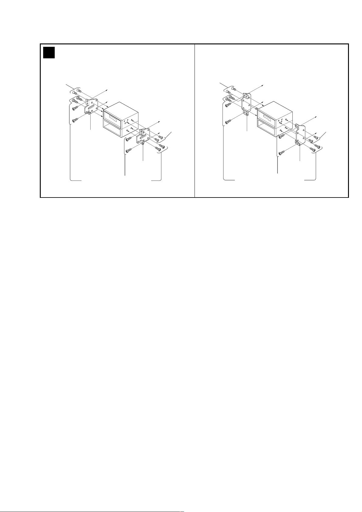
Mounting example (5)
Installation in the dashboard
6
Ejemplo de montaje (5)
Instalación en el salpicadero
XR-CA440/CA440X
6 A
TOYOTA NISSAN
4
max. size
5 × 8 mm
Tamaño máx.
M5 × 8mm
Bracket
Soporte
Existing parts supplied with your car
Piezas existentes suministradas con su automóvil
to dashboard/center console
al salpicadero/consola central
Bracket
Soporte
4
max. size
5 × 8 mm
Tamaño máx.
M5 × 8mm
B
4
max. size
5 × 8 mm
Tamaño máx.
M5 × 8mm
to dashboard/center console
al salpicadero/consola central
Bracket
Soporte
Bracket
Soporte
Existing parts supplied with your car
Piezas existentes suministradas con su automóvil
4
max. size
5 × 8 mm
Tamaño máx.
M5 × 8mm
7
XR-CA440/CA440X
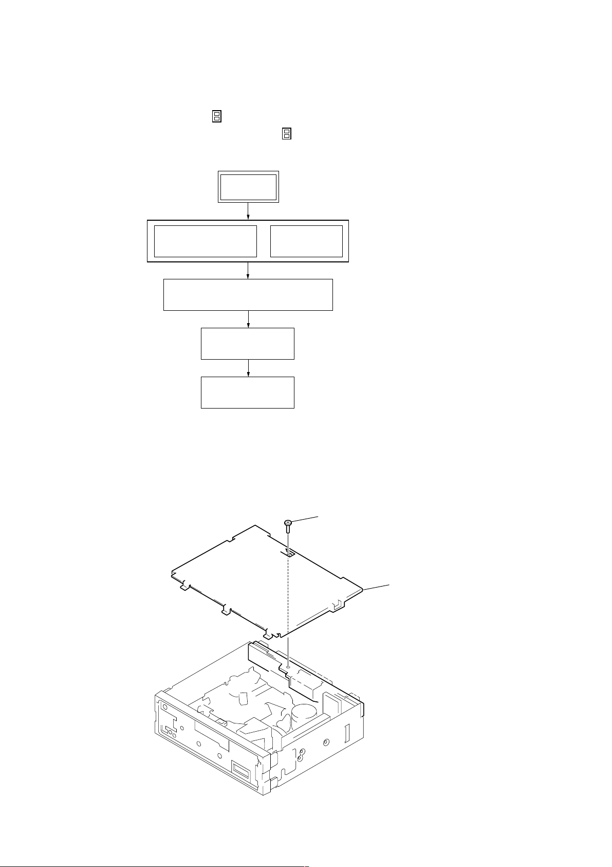
r
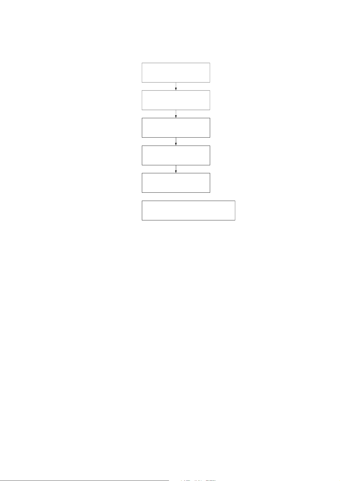
• This set can be disassembled in the order shown below.
2-1. DISASSEMBLY FLOW
Note 1: The process described in can be performed in any order.
Note 2: Without completing the process described in , the next process can not be performed.
Note 3: Illustration of disassembly is omitted.
SECTION 2
DISASSEMBLY
SET
FRONT PANEL SECTION
(Note 3)
2-3. MECHANISM DECK (MG-25F-136)
(Page 9)
2-4. MAIN BOARD
(Page 9)
2-5. HEAT SINK
(Page 10)
Note: Follow the disassembly procedure in the numerical order given.
2-2. COVER
2-2. COVER
(Page 8)
1
screw
(PTT2.6 × 5)
2
cove
8
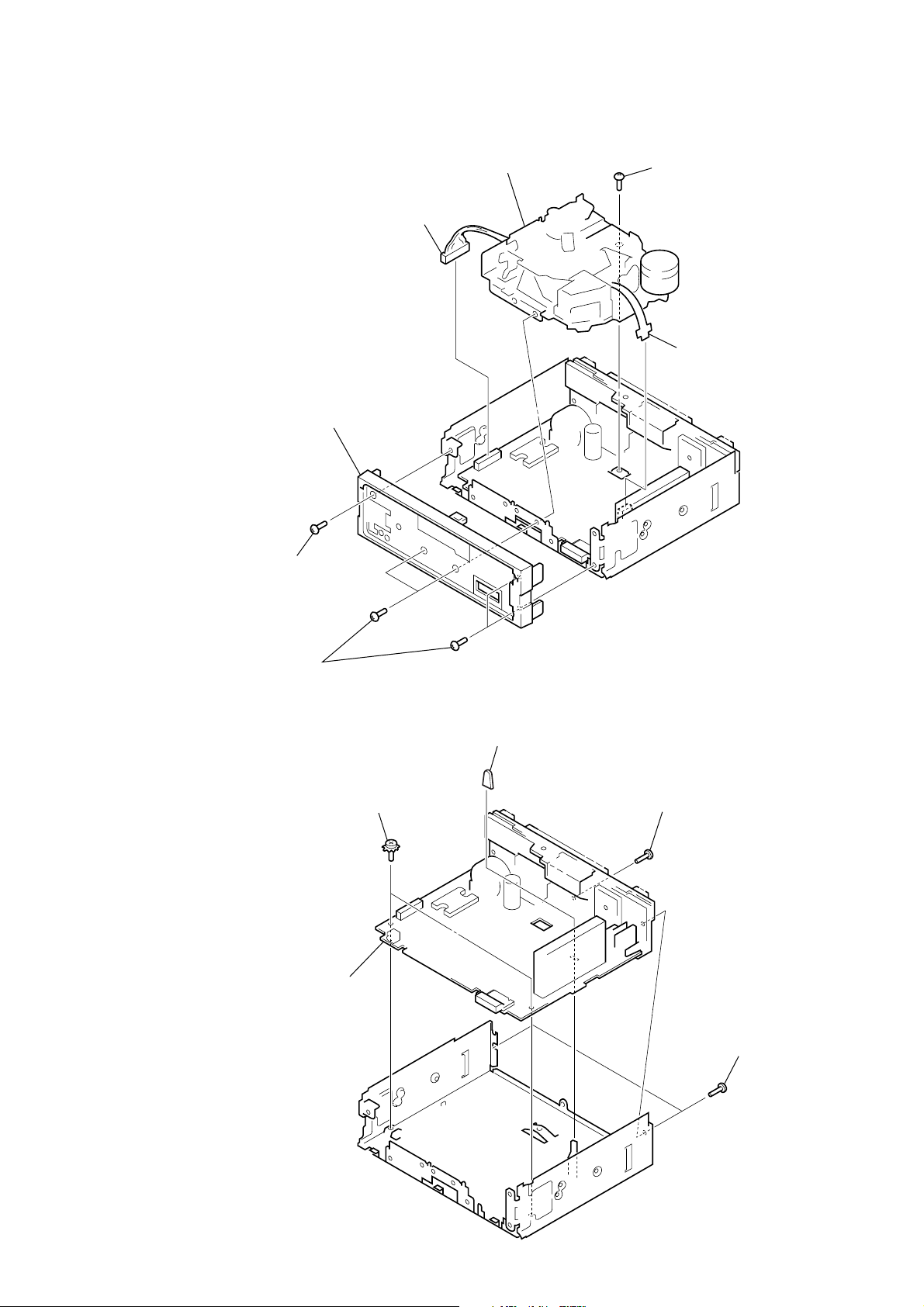
2-3. MECHANISM DECK (MG-25F-136)
)
)
XR-CA440/CA440X
4 connector (CN351)
2 sub panel assy
1 screw (PTT2.6 × 6)
6 mechanism deck
(MG-25F-136)
5 screw (PTT2.6 × 6
3 flexible board
(CNP301)
1 four screws
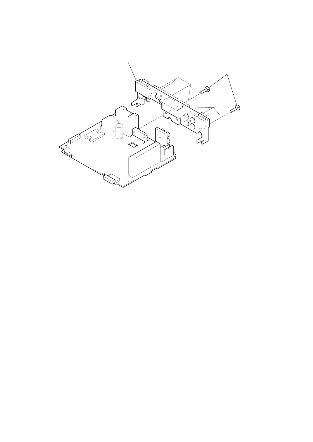
2-4. MAIN BOARD
(PTT2.6 × 6)
4
main board
2
two ground point
screws
3
rubber cap (25)
1
screw (PTT2.6 × 10)
1
two screws
(PTT2.6 × 10
9
XR-CA440/CA440X
)
2-5. HEAT SINK
2
heat sink
1
seven screws
(PTT2.6
×
10
10
ASSEMBLY OF MECHANISM DECK
• This set can be assembled in the order shown below.
3-1. ASSEMBLY FLOW
XR-CA440/CA440X
SECTION 3
3-2. HOUSING
(Page 12)
3-3. ARM (SUCTION)
(Page 12)
3-4. LEVER (LDG-A)/(LDG-B)
(Page 13)
3-5. GEAR (LDG-FT)
(Page 13)
3-6. GUIDE (C)
(Page 14)
3-7. MOUNTING POSITION
OF CAPSTAN/REEL MOTOR (M901)
(Page 14)
11
XR-CA440/CA440X
Note: Follow the assembly procedure in the numerical order given.
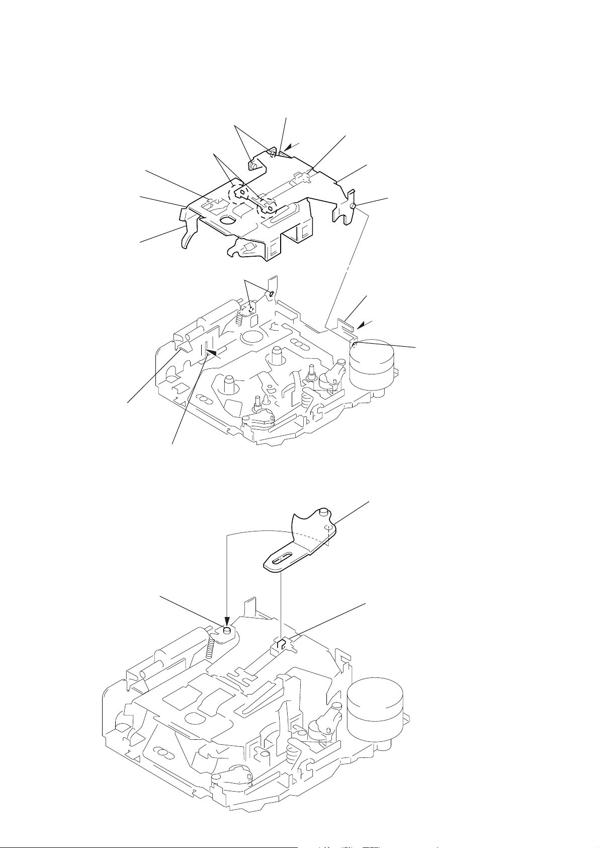
3-2. HOUSING
5 Fit projection on C part.
2 Install the hanger onto
two claws of the housing.
4 Fit claw on B part.
7 Hold the hanger by bending the claw.
1 Install the catch to the hanger.
hanger
3 Put the housing
under A part.
housing
A part
6 Fit projection on D part.
C part
8 Hold the hanger by
bending the claw.
D part
B part
3-3. ARM (SUCTION)
2 Move the arm (suction) in the arrow
direction and fit on projection.
projection
1 Fit the arm (suction) on the shaft.
12
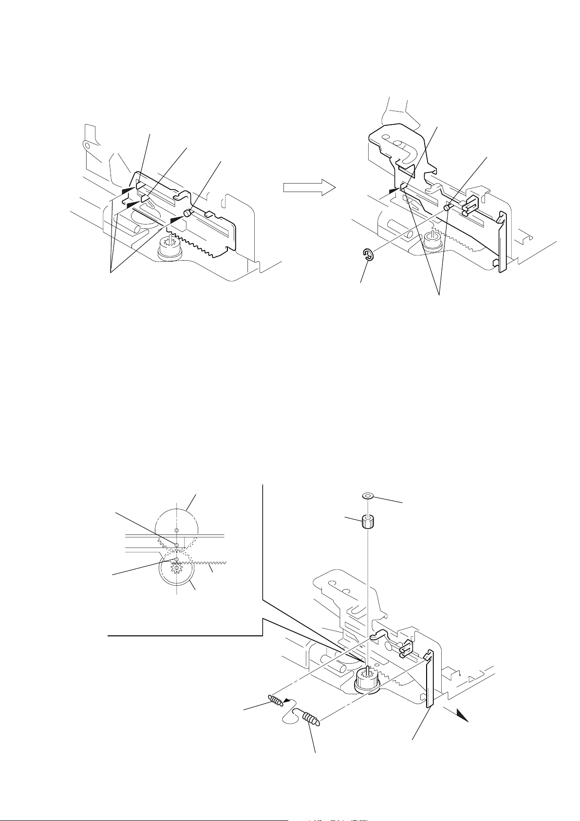
3-4. LEVER (LDG-A) / (LDG-B)
)
XR-CA440/CA440X
shaft A
1 Fit the lever (LDG-A) on
shafts A – C and install it.
shaft B
shaft C
shaft A
shaft B
3 type-E stop ring 2.0
2 Fit the lever (LDG-B) on
shafts A and B and
install it.
3-5. GEAR (LDG-FT)
hole
hole
4 Align hole in the gear (LDG-D)
with hole the lever (LDG-A).
2 tension spring (LD-2)
gear (LDG-D)
6 polyethylene washer
5 gear (LDG-FT)
lever (LDG-A)
gear (LDG-FB)
1
2 tension spring (LD-1)
3 Move the lever (LDG-B
in the arrow direction.
13
 Loading...