

SONY XR-CA440H Service Manual
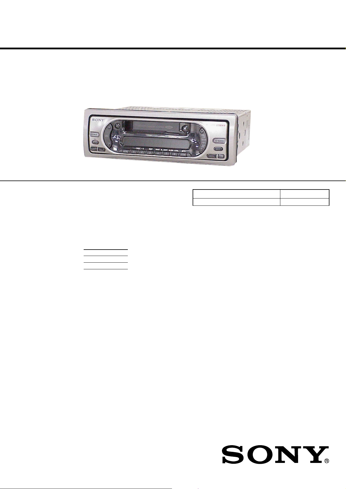
XR-CA440H
SERVICE MANUAL
Ver 1.0 2002.10
SPECIFICATIONS
Cassette Player section
Tape track 4-track 2-channel stereo
Wow and flutter 0.08 % (WRMS)
Frequency response 30 – 18,000 Hz
Signal-to-noise ratio
Tuner section
FM
Tuning range FM tuning interval:
Aerial terminal External aerial connector
Intermediate frequency 10.7 MHz
Usable sensitivity 11 dBf
Selectivity 75 dB at 400 kHz
Signal-to-noise ratio 65 dB (stereo),
Harmonic distortion at 1 kHz
Separation 33 dB at 1 kHz
Frequency response 30 – 15,000 Hz
Cassette type
TYPE II, IV 61 dB
TYPE I
50 kHz/200 kHz switchable
87.5 – 108.0 MHz
(at 50 kHz step)
87.5 – 107.9 MHz
(at 200 kHz step)
68 dB (mono)
0.7 % (stereo),
0.5 % (mono)
58 dB
MW
Tuning range MW tuning interval:
Sensitivity 30 µV
SW
Tuning range SW tuning interval:
Aerial terminal External aerial connector
Intermediate frequency 10.7 MHz/450 kHz
Sensitivity 40 µV
Power amplifier section
Outputs Speaker outputs
Speaker impedance 4 – 8 ohms
Maximum power output 50 W × 4 (at 4 ohms)
9 kHz/10 kHz switchable
531 – 1,602 kHz
(at 9 kHz step)
530 – 1,710 kHz
(at 10 kHz step)
SW1: 2,940 – 7,735 kHz
SW2: 9,500 – 18,135 kHz
(except for 10,140 – 11,575
kHz)
(sure seal connectors)
E Model
Model Name Using Similar Mechanism XR-CA440X
Tape Transport Mechanism T ype MG-25F-136
General
Outputs Audio outputs
Inputs BUS control input term ina l
Tone controls Bass ±9 dB at 100 Hz
Power requirements 12 V DC car battery
Dimensions Approx. 178 × 50 × 178
Mounting dimensions Approx. 182 × 53 × 161
Mass Approx. 1.2 kg
Supplied accessories Parts for installation and
Note
This unit cannot be connected to a digital preamplifier
or an equalizer.
Design and specifications are subject to change
without notice.
Power aerial relay control
lead
Power amplifier contro l lead
BUS audio input terminal
Aerial input terminal
Treble ±9 dB at 10 kHz
(negative eart h )
mm (w/h/d)
mm (w/h/d)
connections (1 set)
Front panel case (1)
9-874-206-01 Sony Corporation
2002J0500-1 e Vehicle Company
C 2002.10 Published by Sony Engineering Corporation
FM/MW/SW CASSETTE CAR STEREO

XR-CA440H
TABLE OF CONTENTS
1. GENERAL
Location of Controls ....................................................... 3
Setting the Clock ............................................................. 3
2. DISASSEMBLY
2-1. Disassembly Flow ........................................................... 4
2-2. Collar ............................................................................... 4
2-3. Cover ............................................................................... 5
2-4. Mechanism Deck (MG-25F-136) ................................... 5
2-5. MAIN Board ................................................................... 6
2-6. Heat Sink ......................................................................... 6
3. ASSEMBLY OF MECHANISM DECK
3-1. Assembly Flow................................................................ 7
3-2. Housing ........................................................................... 8
3-3. Arm (Suction) ................................................................. 8
3-4. Lever (LDG-A)/(LDG-B) ............................................... 9
3-5. Gear (LDG-FT) ............................................................... 9
3-6. Guide (C)......................................................................... 10
3-7. Mounting Position of Capstan/Reel Motor (M901)....... 10
4. MECHANICAL ADJUSTMENTS....................... 11
5. ELECTRICAL ADJUSTMENTS
Tape Dec k Section .......................................................... 11
Tuner Section .................................................................. 11
Notes on chip component replacement
•Never reuse a disconnected chip component.
• Notice that the minus side of a tantalum capacitor may be damaged by heat.
Flexible Circuit Board Repairing
•Keep the temperature of the soldering iron around 270 ˚C during repairing.
• Do not touch the soldering iron on the same conductor of the
circuit board (within 3 times).
• Be careful not to apply force on the conductor when soldering
or unsoldering.
6. DIAGRAMS
6-1. Note for Printed Wiring Boards and
Schematic Diagrams ....................................................... 13
6-2. Printed Wiring Board – MAIN Board – ......................... 14
6-3. Schematic Diagram – MAIN Board (1/3) – ................... 15
6-4. Schematic Diagram – MAIN Board (2/3) – ................... 16
6-5. Schematic Diagram – MAIN Board (3/3) – ................... 17
6-6. Printed Wiring Board – KEY Board –............................ 18
6-7. Schematic Diagram – KEY Board – .............................. 19
6-8. IC Pin Function Description ........................................... 21
7. EXPLODED VIEWS
7-1. Chassis Section ............................................................... 24
7-2. Front Panel Section ......................................................... 25
7-3. MAIN Board Section ...................................................... 26
7-4. Mechanism Deck Section (MG-25F-136) ...................... 27
8. ELECTRICAL PARTS LIST ............................... 28
2
SECTION 1
GENERAL
XR-CA440H
This section is extracted from
instruction manual.
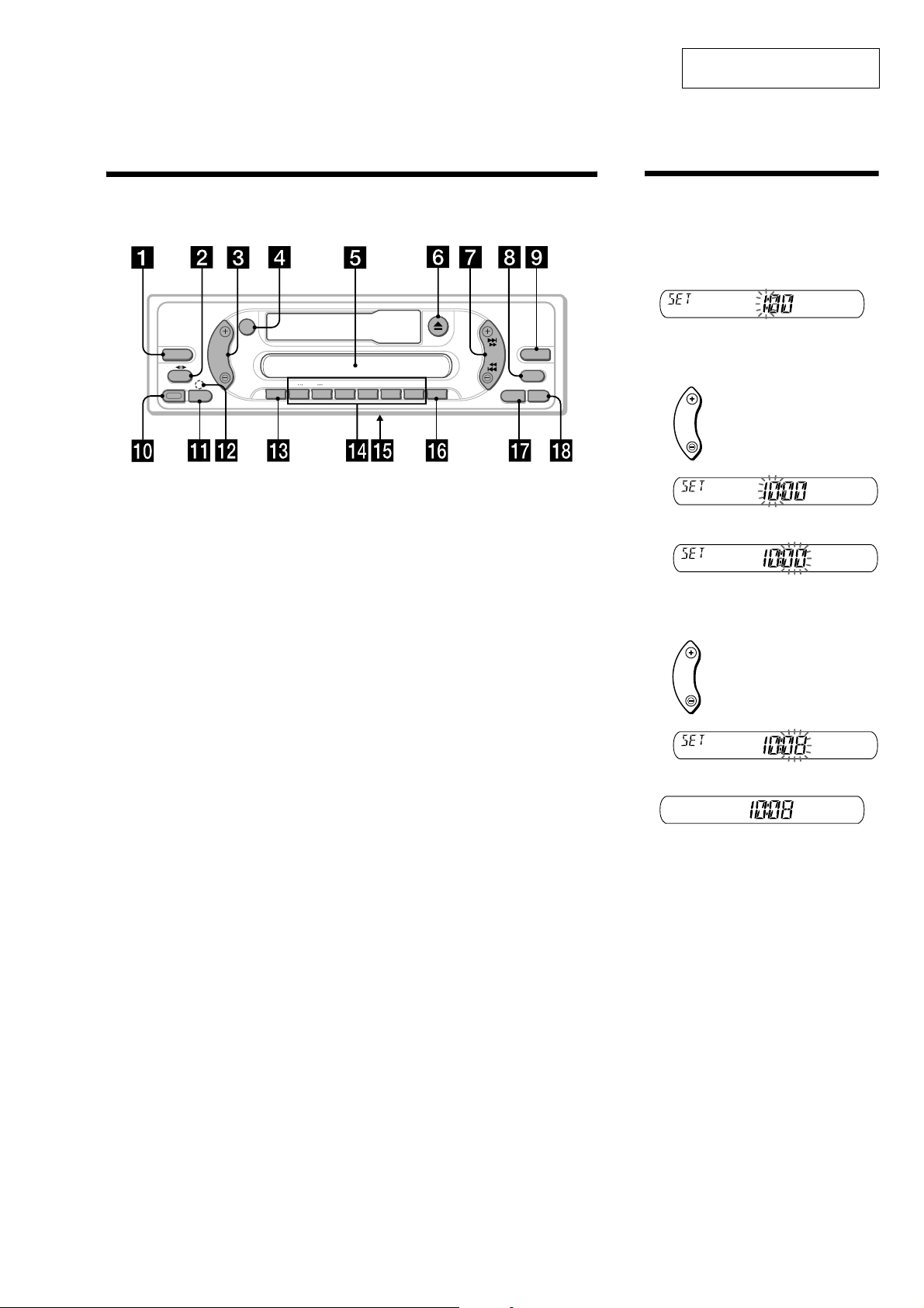
Location of controls
Refer to the pages listed for details.
ATT
MODE
SEL
VOL
+
DISC
—
SENS
123456
SOURCE
RELEASE
a SOURCE (Power on/Tape/Radio/CD/
MD) select button
b MODE (o) button
Selecting the source.
c VOL +/– button
d AT T (attenuate) button
e Display window
f Z (eject) button 8
g SEEK/AMS button
Tap e:
Fast-forwarding, reversing a tape
Radio:
Tuning in stations automatically.
Finding a station manually.
CD (MP3 files)/MD:
Skipping tracks.
h MBP (My Best sound Position) button
12
i D-BASS button 12
j RELEASE (front panel release) button
k SEL (select) button
Selecting items.
l RESET button (located on the front side of
the unit, behind the front panel) 6
m SENS button
Storing the stations with the strongest
signals.
SEEK
D-BASS
AMS
REP
SHUF BL
SKIP/ ALBM
-+/ATA
MTL
BTM
MBP
OFFDSPL
n Number buttons
Tap e:
(3): REP (Repeat)
(5): BL SKIP (Blank Skip)
(6): ATA (Automatic Tuner Activation)
Radio:
Storing the desired station on each number
button.
CD (MP3 files)/MD:
(1): DISC –
(2): DISC +
(3): REP (Repeat)
(4): SHUF (Shuffle)
MP3 files:
(5): ALBM –
(6): ALBM +
o Frequency select switch (located on
the bottom of the unit)
See “Frequency select switch” in the
Installation/Connections manual.
p BTM/MTL (Best Tuning Memory/Metal)
button 9
q DSPL (display mode change) button
r OFF (Stop/Power off) button*
* Warning when installing in a car without
an ACC (accessory) position on the
ignition switch
After turning off the ignition, be sure to press
(OFF) on the unit for 2 seconds to turn off
the clock display.
Otherwise, the clock display does not turn off
and this causes battery drain.
Setting the clock
The clock uses a 12-hour digital indication.
Example: To set the clock to 10:08
1
Press (DSPL) for 2 seconds.
The hour indication flashes.
1Press either side of (VOL) to set the
hour.
to go forward
VOL
to go back
2Press (SEL).
The minute indication flashes.
3Press either side of (VOL) to set the
minute.
to go forward
VOL
to go back
2
Press (DSPL).
The clock starts.
After the clock setting is completed, the
display returns to normal play mode.
3
XR-CA440H
• This set can be disassembled in the order shown below.
2-1. DISASSEMBLY FLOW
Note 1: The process described in can be performed in any order.
Note 2: Without completing the process described in , the next process can not be performed.
Note 3: Illustration of disassembly is omitted.
SECTION 2
DISASSEMBLY
SET
FRONT PANEL SECTION
(Note 3)
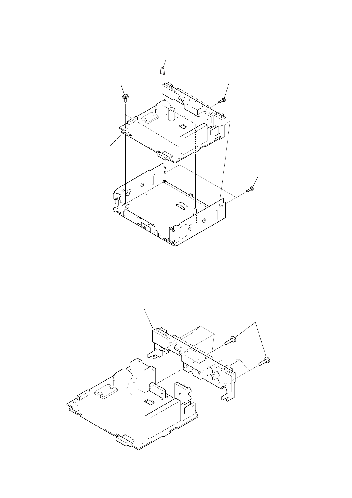
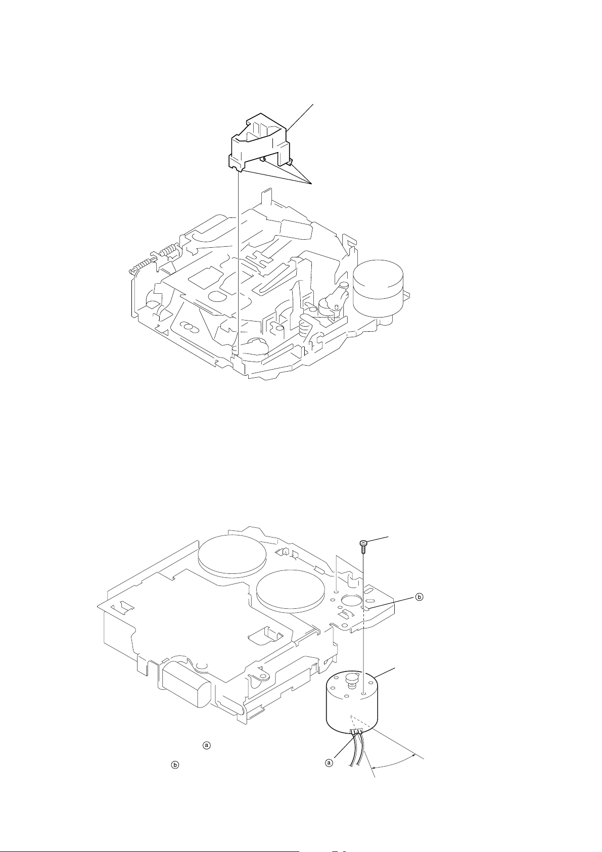
2-4. MECHANISM DECK (MG-25F-136)
(Page 5)
2-5. MAIN BOARD
(Page 6)
2-6. HEAT SINK
(Page 6)
Note: Follow the disassembly procedure in the numerical order given.
2-2. COLLAR
2-2. COLLAR
(Page 4)
2-3. COVER
(Page 5)
3
Remove the bracket
1
screw
(K5 × 8)
A
2
in the direction of arrow A.
B
5
collar
4
Remove the bracket
in the direction of arrow B.
1
screw
(K5 × 8)
4
r
2-3. COVER
)
1
screw
(PTT2.6 × 5)
2
XR-CA440H
cove
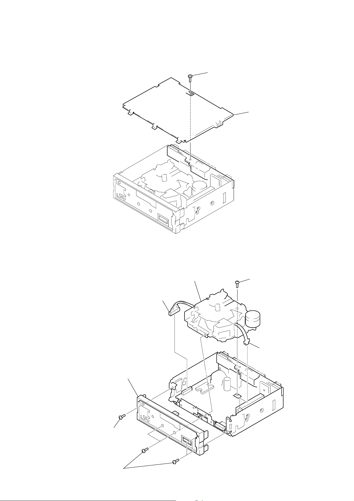
2-4. MECHANISM DECK (MG-25F-136)
4
connector (CN351)
2
sub panel assy
6
mechanism deck (MG-25F-136)
5
screw (PTT2.6 × 6
3
flexible board
(CN301)
1
screw (PTT2.6 × 6)
1
four screws
(PTT2.6 × 6)
5
XR-CA440H
)
)
2-5. MAIN BOARD
4
main board
2
two ground point
screws
3
rubber cap (25)
1
screw (PTT2.6 × 10)
1
two screws
(PTT2.6 × 10
2-6. HEAT SINK
2
heat sink
1
seven screws
(PTT2.6
×
10
6
ASSEMBLY OF MECHANISM DECK
• This set can be assembled in the order shown below.
3-1. ASSEMBLY FLOW
XR-CA440H
SECTION 3
3-2. HOUSING
(Page 8)
3-3. ARM (SUCTION)
(Page 8)
3-4. LEVER (LDG-A)/(LDG-B)
(Page 9)
3-5. GEAR (LDG-FT)
(Page 9)
3-6. GUIDE (C)
(Page 10)
3-7. MOUNTING POSITION
OF CAPSTAN/REEL MOTOR (M901)
(Page 10)
7
XR-CA440H
Note: Follow the assembly procedure in the numerical order given.
3-2. HOUSING
5 Fit projection on C part.
2 Install the hanger onto
two claws of the housing.
4 Fit claw on B part.
7 Hold the hanger by bending the claw.
1 Install the catch to the hanger.
hanger
3 Put the housing
under A part.
housing
A part
6 Fit projection on D part.
C part
8 Hold the hanger by
bending the claw.
D part
B part
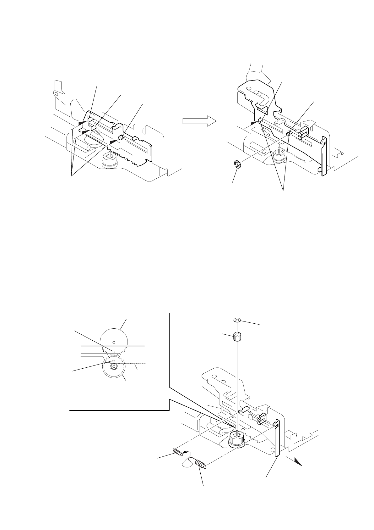
3-3. ARM (SUCTION)
2 Move the arm (suction) in the arrow
direction and fit on projection.
projection
1 Fit the arm (suction) on the shaft.
8
3-4. LEVER (LDG-A) / (LDG-B)
)
XR-CA440H
shaft A
1 Fit the lever (LDG-A) on
shafts A – C and install it.
shaft B
shaft C
shaft A
shaft B
3 type-E stop ring 2.0
2 Fit the lever (LDG-B) on
shafts A and B and
install it.
3-5. GEAR (LDG-FT)
hole
hole
4 Align hole in the gear (LDG-D)
with hole the lever (LDG-A).
2 tension spring (LD-2)
gear (LDG-D)
6 polyethylene washer
5 gear (LDG-FT)
lever (LDG-A)
gear (LDG-FB)
1
2 tension spring (LD-1)
3 Move the lever (LDG-B
in the arrow direction.
9
XR-CA440H
s
3-6. GUIDE (C)
2 guide (C)
1 three claws
3-7. MOUNTING POSITION OF CAPSTAN/REEL MOTOR (M901)
Note: Mount the motor so that the
angle between of the
motor and the hole for the
screw becomes 30
shown in this figure.
°
as
two precision screw
(P2 × 2)
capstan/reel motor
(M901)
30˚
10
SECTION 4
r
MECHANICAL ADJUSTMENTS
XR-CA440H
SECTION 5
ELECTRICAL ADJUSTMENTS
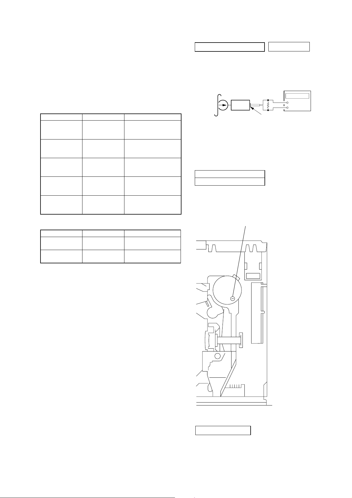
1. Clean the f ollowing parts with a denatured-alcohol-moistened
swab:
playback head pinch roller
rubber belt capstan
idler
2. Demagnetize the playback head with a head demagnetizer.
3. Do not use a magnetized screwdriver for the adjustments.
4. The adjustments should be performed with the power supply
voltage (14.4 V) unless otherwise noted.
TORQUE MEASUREMENT
Mode Torque Meter Meter Reading
Forward CQ-102C (30 – 65 g•cm)
Forward
Back Tension
Reverse CQ-102RC (30 – 65 g•cm)
Reverse
Back Tension
FF, REW CQ-201B (60 – 200 g•cm)
CQ-102C (0.5 – 4.5g•cm)
CQ-102RC (0.5 – 4.5g•cm)
2.95 – 6.37 mN•m
(0.42 – 0.90 oz•inch)
0.05 – 0.44 mN•m
(0.01 – 0.06 oz•inch)
2.95 – 6.37 mN•m
(0.42 – 0.90 oz•inch)
0.05 – 0.44 mN•m
(0.01 – 0.06 oz•inch)
5.89 – 19.61 mN•m
(0.83 – 2.78 oz•inch)
TAPE DECK SECTION
0 dB=0.775 V
TAPE SPEED ADJUSTMENT
Setting:
test tape
WS-48A
(3 kHz, 0 dB)
set
frequency counte
10 kΩ
+
–
AUDIO OUT jack (J331)
Procedure:
1. Put the set into the FWD PB mode.
2. Adjust adjustment resistor for inside capstan motor so that the
reading on the frequency counter becomes 3,000 Hz.
Specified Value: Constant speed
Frequency counter
2,955 to 3,075 Hz
Adjustment Location:
– SET UPPER VIEW –
TAPE TENSION MEASUREMENT
Mode Tension Meter Meter Reading
Forward CQ-403A
Reverse CQ-403R
(more than 2.12 oz)
(more than 2.12 oz)
Tape Speed Adjustment
more than 60 g
more than 60 g
TUNER SECTION
Tuner section adjustments are done automatically in this set.
11
 Loading...