

Sony XR-C553SP Service manual
XR-C553SP
SERVICE MANUAL
Ver 1.1 2001.08
For RM-X2S (Remote Commander),
please reter to RM-X2S/X3S Service
Manual (9-960-039-∏) previously issued.
East European Model
Dolby noise reduction manufactured under license
from Dolby Laboratories Licensing Corporation.
“DOLBY” and the double-D symbol a are trademarks
of Dolby Laboratories Licensing Corporation.
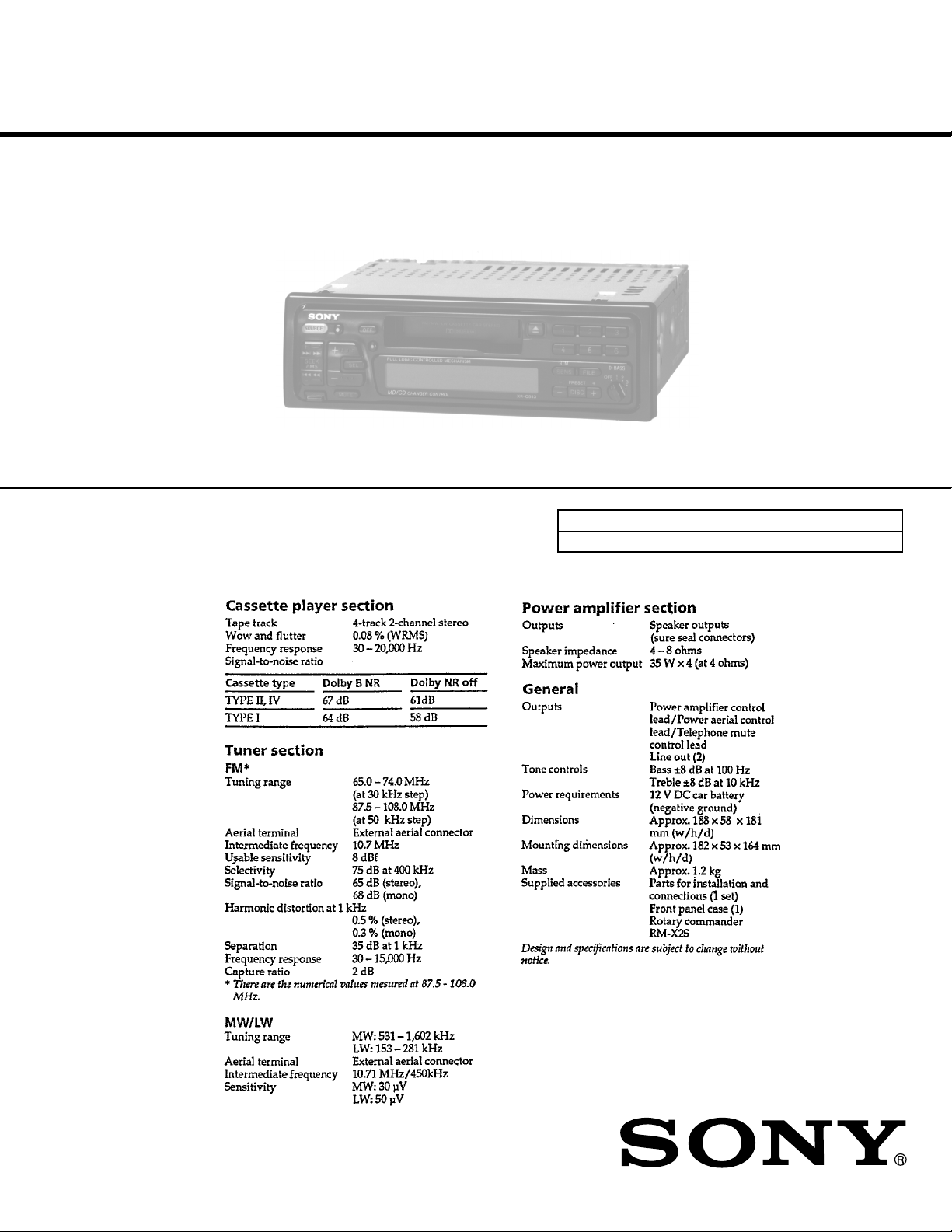
SPECIFICATIONS
Model Name Using Similar Mechanism NEW
T ape Transport Mechanism T ype
MG-52A-135
FM/MW/LW CASSETTE CAR STEREO
9-925-531-12 Sony Corporation
2001H0500-1 e Vehicle Company
C 2001.8 Shinagawa Tec Service Manual Production Group

TABLE OF CONTENTS
SERVICING NOTES
1. GENERAL
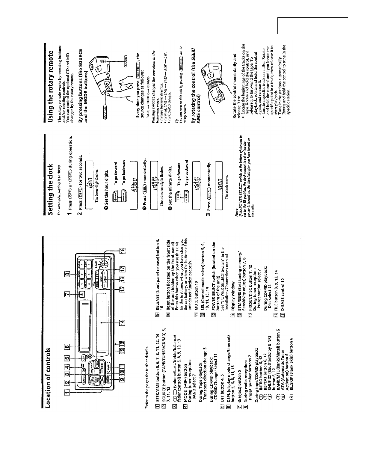
Location of Controls .......................................................... 3
Setting the Clock ............................................................... 3
Using the Rotary Remote .................................................. 3
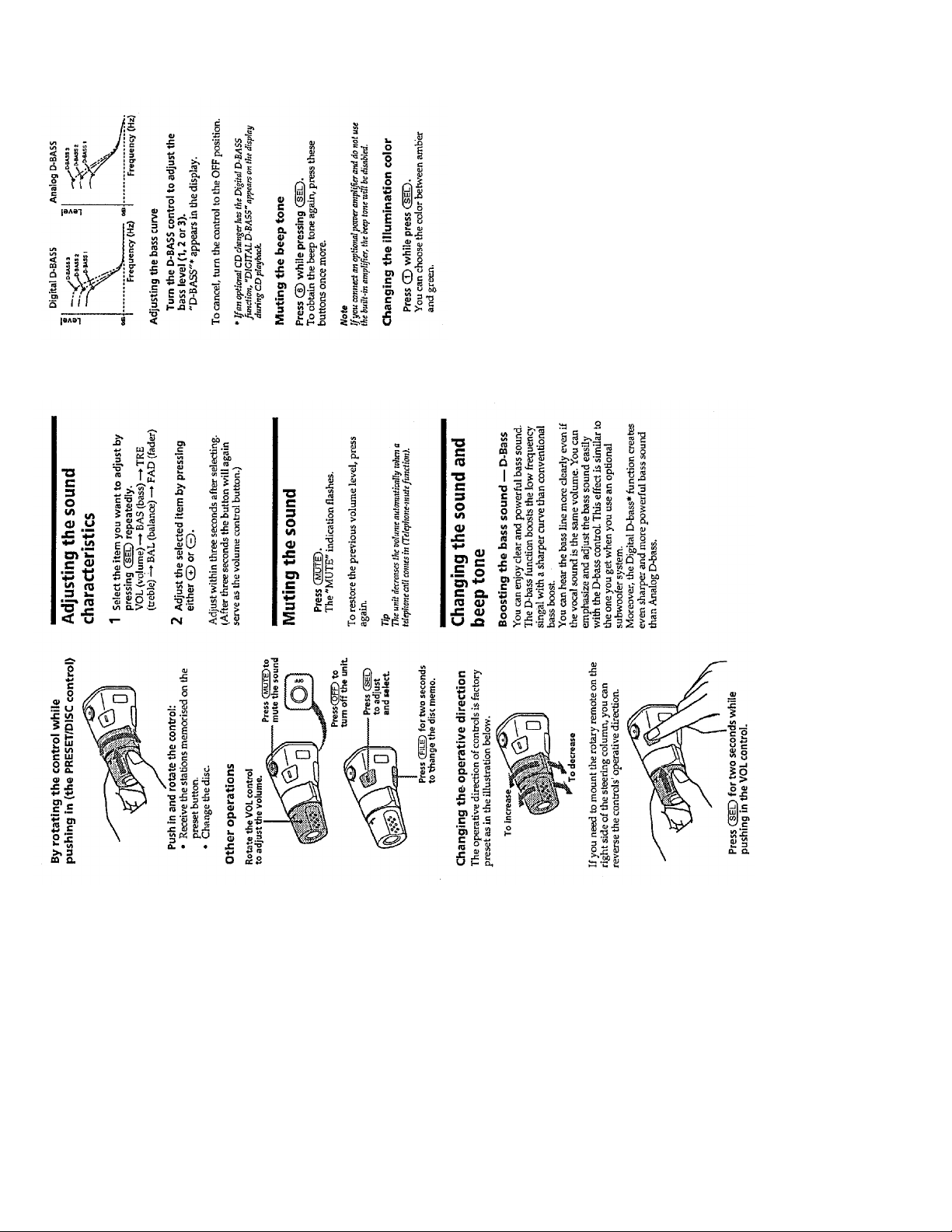
Adjusting the Sound Characteristics ................................. 4
Muting the Sound .............................................................. 4
Changing the Sound and Beep Tone .................................. 4
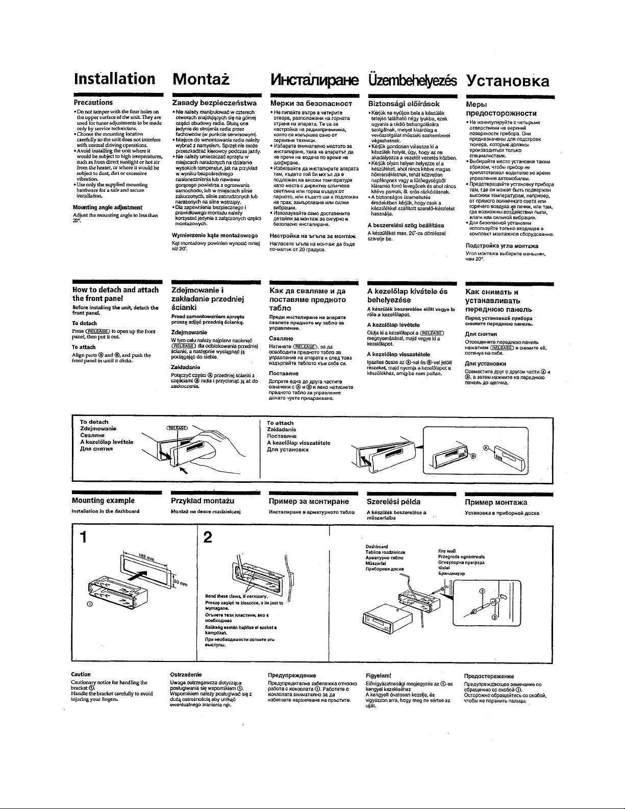
Installation ......................................................................... 5
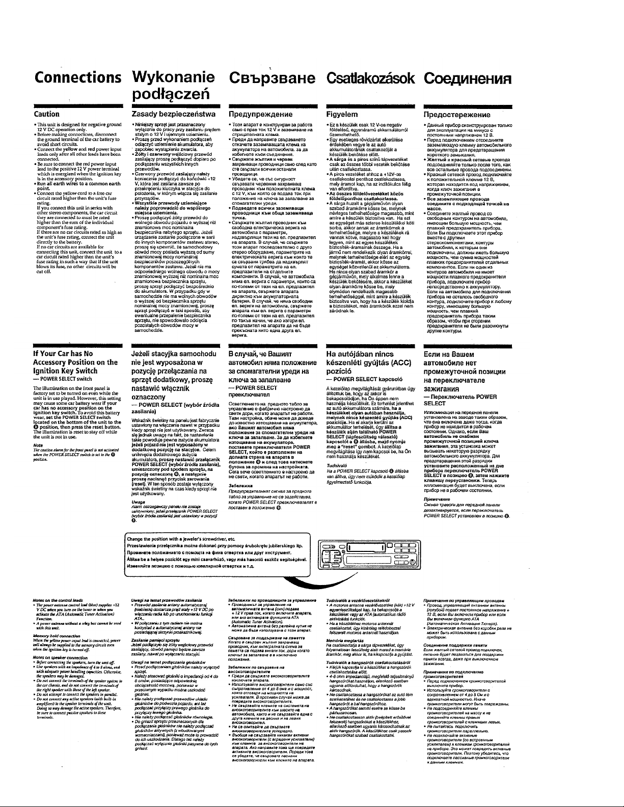
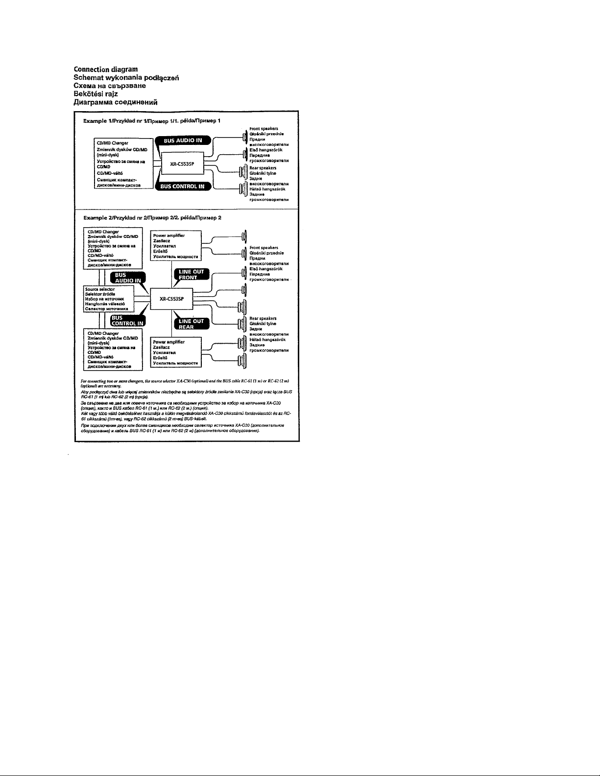
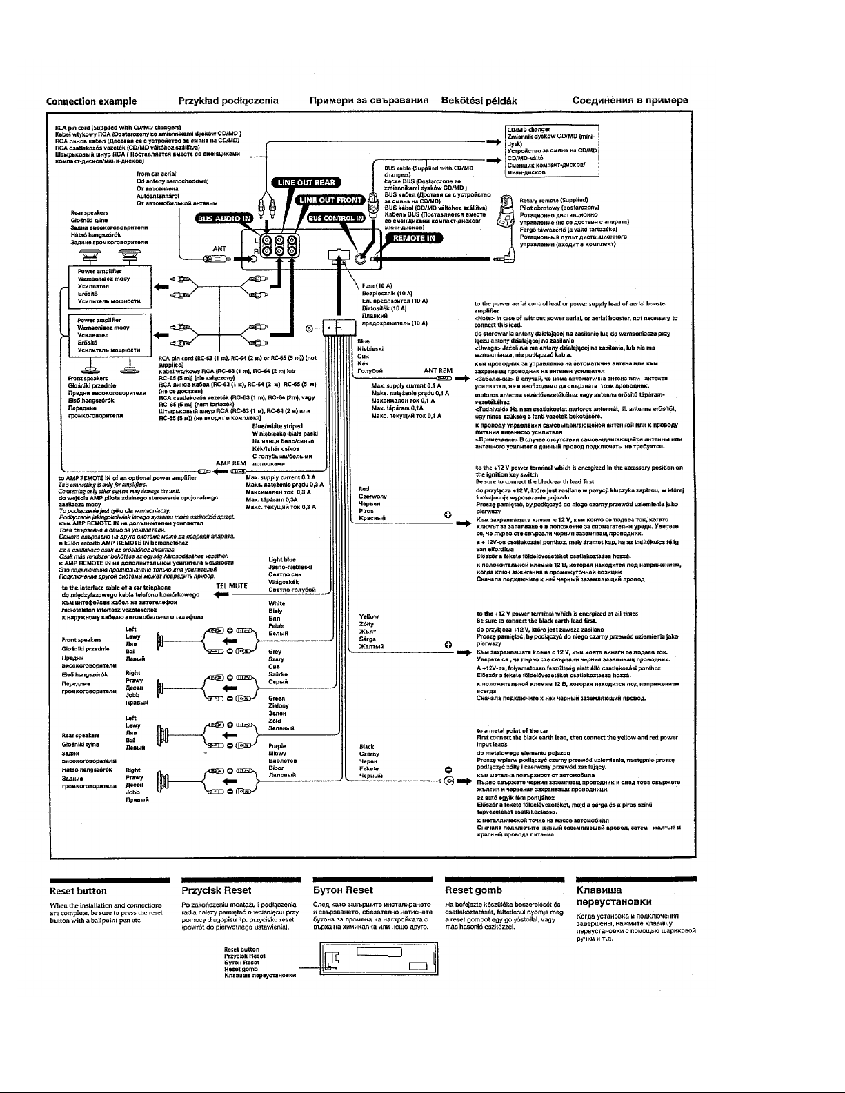
Connections ....................................................................... 6
2. DISASSEMBLY............................................................ 9
3. ASSEMBLY OF MECHANISM DECK............... 11
4. MECHANICAL ADJUSTMENTS ......................... 17
5. ELECTRICAL ADJUSTMENTS
Test Mode .......................................................................... 17
Tape Deck Section ............................................................. 17
Tuner Section..................................................................... 18
6. DIAGRAMS
6-1. IC Pin Function Description.............................................. 22
6-2. Block Diagram (1/2).......................................................... 25
6-3. Block Diagram (2/2).......................................................... 27
6-4. Printed Wiring Boards –Main Section– ............................ 29
6-5. Schematic Diagram –Main Section– ................................ 33
6-6. Printed Wiring Board –Display Section– ......................... 37
6-7. Schematic Diagram –Display Section– ............................ 39
Flexible Circuit Board Repairing
• Keep the temperature of the soldering iron around 270 ˚C during
repairing.
• Do not touch the soldering iron on the same conductor of the
circuit board (within 3 times).
• Be careful not to apply force on the conductor when soldering or
unsoldering .
Notes on chip component replacement
• Never reuse a disconnected chip component.
• Notice that the minus side of a tantalum capacitor may be dam-
aged by heat.
7. EXPLODED VIEWS .................................................. 44
8. ELECTRICAL PARTS LIST .................................. 48
– 2 –
SECTION 1
GENERAL
This section is extracted
from instruction manual.
– 3 –
– 4 –
– 5 –
– 6 –
– 7 –
– 8 –
SECTION 2
DISASSEMBLY
Note: Follow the disassembly procedure in the numerical order given.
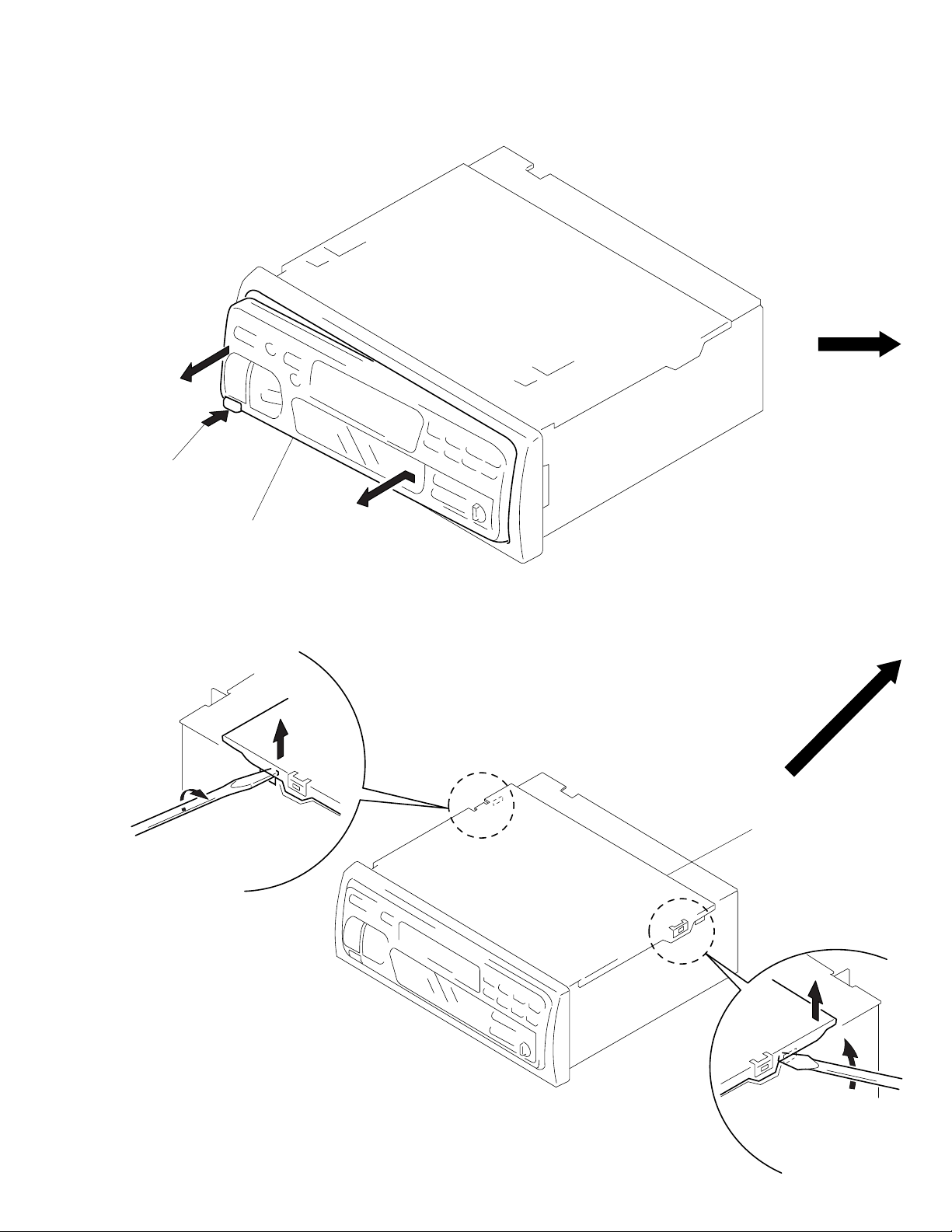
FRONT PANEL ASS’Y
1
Push the button
(release)
A
2
Remove the front panel ass’y
to the direction of the arrow A.
COVER ASS’Y
1
2
3
cover ass’y
2
1
– 9 –
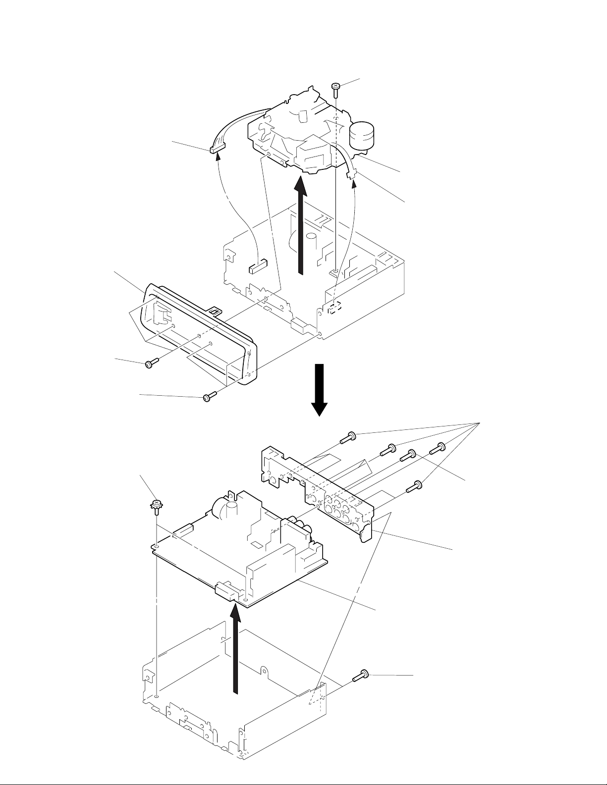
SUB PANEL, MECHANISM DECK (MG-52A-135)
3
connector
(CN302)
2
sub panel
1
three screws
(PTT2.6 × 8)
5
screw
(PTT2.6 × 6)
6
mechanism deck
(MG-52A-135)
4
flexible flat cable
(CN301)
1
three screws
(PTT2.6 × 8)
MAIN BOARD, HEAT SINK
2
two ground point
screws
3
main board
1
two screws
(PTT2.6 × 8)
1
5
heat sink
4
nine screws
(PTT2.6 × 10)
screw
(PTT2.6 × 8)
– 10 –
SECTION 3
ASSEMBLY OF MECHANISM DECK
Note: Follow the assembly procedure in the numerical order given.
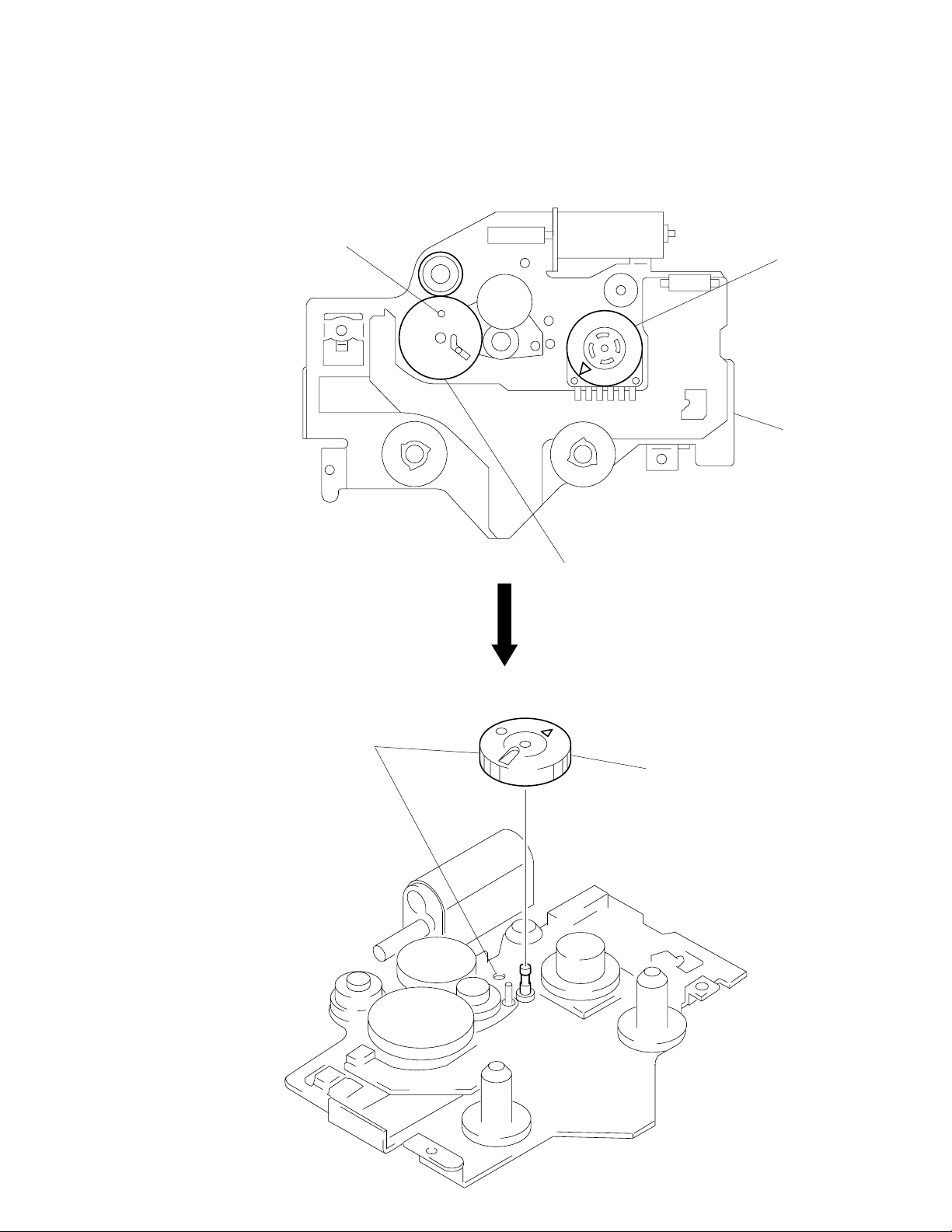
ALIGNMENT OF FRONT SWITCH
hole
1
Align ¢ mark on the rotary switch
the position shown in the figure.
chassis (S) ass’y
GEAR (LDGE)
1
Align hole as shown in the figure.
2
Align hole in the gear (LDG-D) with the
position shown in the figure.
2
Install the gear (LDG-E).
– 11 –
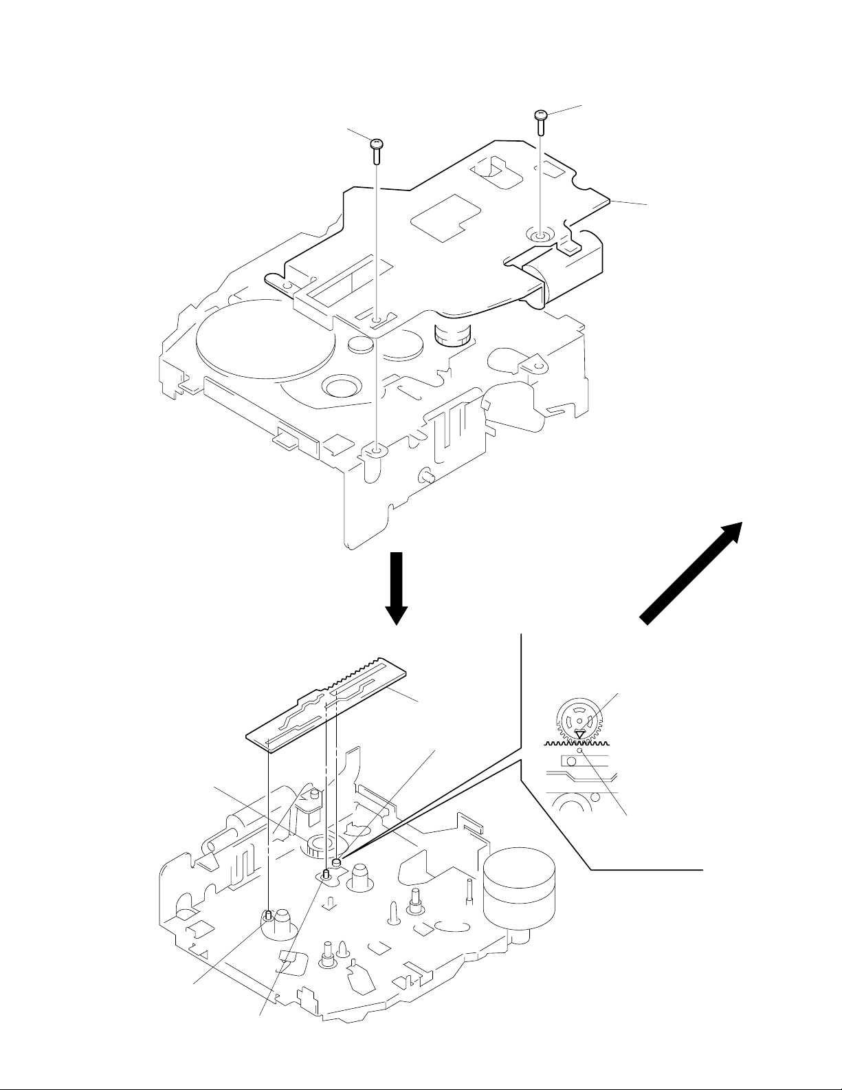
CHASSIS (S) ASS’Y
2
screw (PS2 × 4)
2
screw (PS2 × 4)
1
chassis (S) ass’y
LEVER (MODE)
1. Align ¢ mark on the rotary switch with
hole in the lever (mode).
2. Fit on positions A, B and C and install
the lever (mode).
rotary switch
A
lever (mode)
C
¢
mark on rotary switch
hole in lever (mode)
B
– 12 –
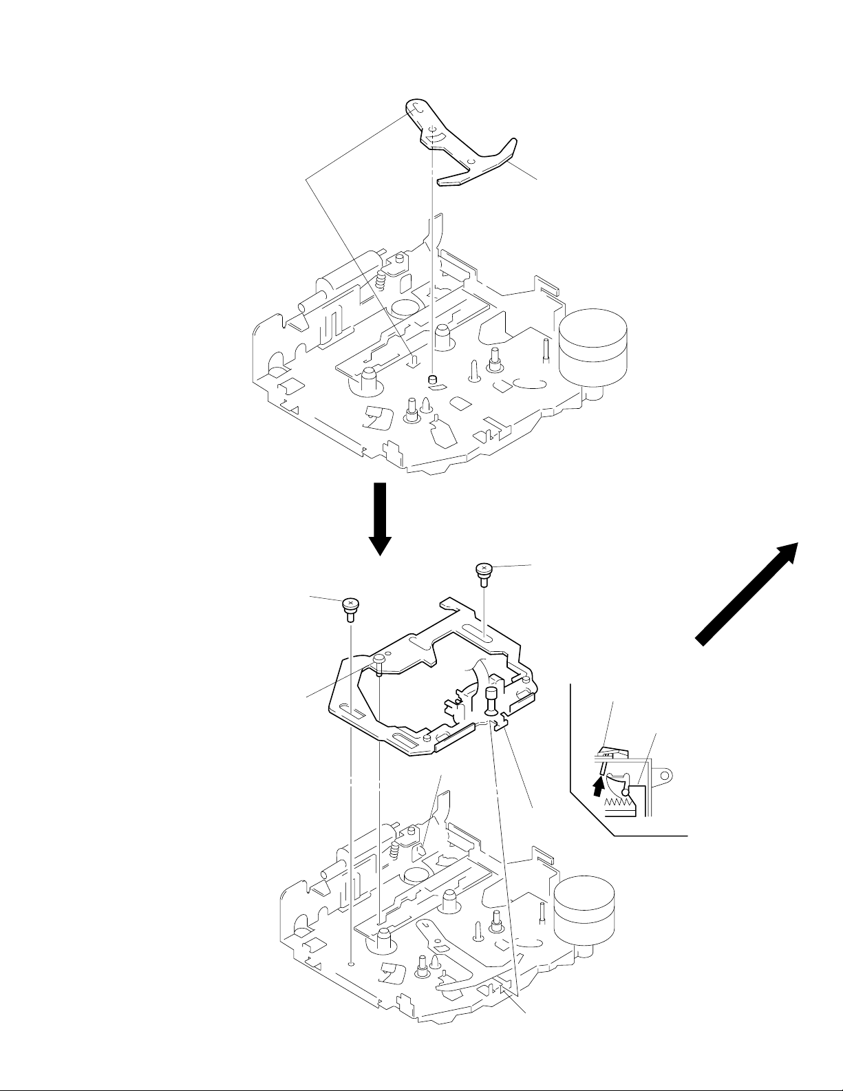
LEVER (PINCH SELECTION)
1
Align.
2
lever (pich selection)
HEAD PLATE ASS’Y
5
2
Fit shaft in groove.
step screw (HP)
ATS lever
5
1
Fit in groove.
step screw (HP)
3
Press the ATS lever.
4
Position the head plate sub
ass’y as shown in the figure.
– 13 –
groove
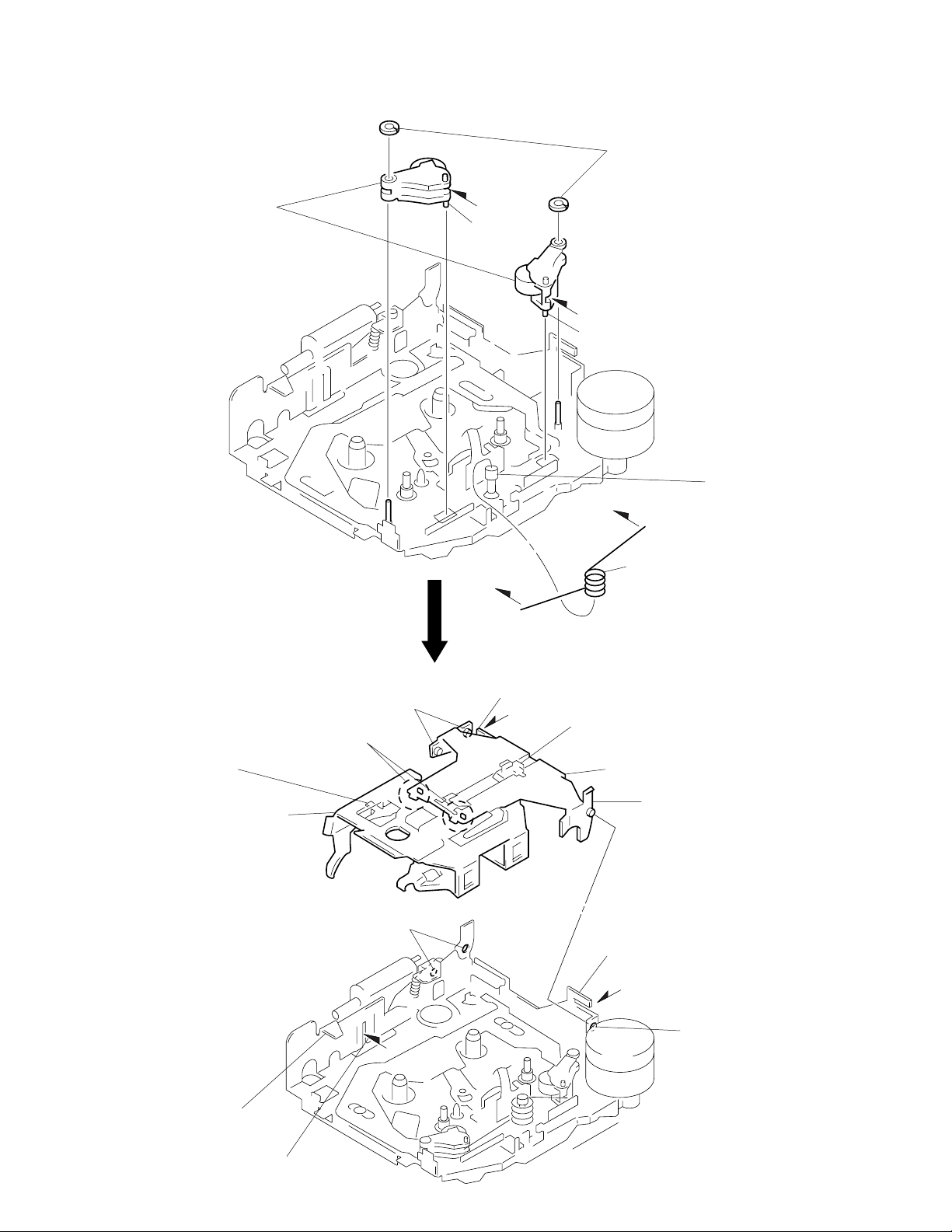
LEVER (PINCH) ASS’Y
2
two polyethylene washers
1
Fit shaft of the lever (Pinch) ass’y
in hole on the chassis (M) ass’y and
install the lever (pinch) ass’y.
B
shaft
B
C
shaft
shaft
A
C
3
Install the spring (pinch press) to shaft A.
Set the ends of spring to B and C.
HOUSING
4
Fit claws on B part.
3
2
Install the hanger on to
two claws of the housing.
Put the housing
under A part.
5
Fit projections on C part.
C
part
7
Holder the hanger by bending the claw.
1
Install the catch to the hanger.
hanger
6
Fit projections on D part.
8
Holder the hanger by
bending the claw.
D
part
A
part
B
part
– 14 –
 Loading...