

Page 1

4-696-257-11(1)
Remote Controller
Operating Instructions
Before operating the unit, please read this manual thoroughly
and retain it for future reference.
RM-IP500
© 2017 Sony Corporation
Page 2

Table of Contents
Introduction
Using This Manual ................................................4
Features ..................................................................4
Location and Function of Parts ............................5
Top .....................................................................5
Rear ..................................................................10
Side / front ........................................................11
Menu Operations .................................................12
Basic menu operations .....................................12
Getting Started
Connections ..........................................................14
VISCA over IP (LAN) connection ...................14
VISCA RS-422 (serial) connection ..................21
Connection with a video switcher ....................24
Using a Setup PC .................................................25
Accessing a remote controller ..........................25
Saving configuration data on a PC (Backup) ...25
Loading a saved configuration file into the
unit or another remote controller (Restore) ....26
About the RM-IP Setup Tool ........................... 26
Operations
Turning on the Power ..........................................27
Selecting a Camera ..............................................27
Selecting a camera when using LAN
connection ......................................................27
Selecting a camera when using serial
connection ......................................................28
About the color of camera buttons ...................28
About the tally lamp indicators ........................28
Operating a Camera ............................................29
Pan and tilt control ...........................................29
Zoom control ....................................................30
Adjusting a Camera ............................................31
Adjusting the focus ..........................................31
Adjusting the brightness ...................................31
Backlight compensation ...................................32
Flicker compensation .......................................32
Adjusting the white balance .............................32
Adjusting the black balance .............................33
Storing the Camera Status (Preset Function) ...34
Recalling stored status .....................................34
Changing the speed of movement between
positions .........................................................34
Operating the Camera Setup Menu from the Unit
(Camera Menu Operation Mode) ...................... 35
Buttons and knobs used for camera menu
operations ....................................................... 35
Setting Specific Functions using Shortcuts
(FUNCTION Menu) ........................................... 37
Buttons and knobs used for FUNCTION menu
operations ....................................................... 37
Operation using IRIS, GAIN, and SHUTTER
buttons ........................................................... 37
Operation using ASSIGN 4, ASSIGN 5, and
ASSIGN 6 ...................................................... 38
Checking Camera Settings Status (Status
Display) ................................................................ 38
Restoring Factory Default Settings ................... 39
Default values .................................................. 39
Function of Buttons/Knobs in Each Block by
Camera Model ..................................................... 41
RM Menu List
OPERATION ....................................................... 43
EXPOSURE ..................................................... 43
WHITE ............................................................ 43
BLACK ............................................................ 44
DETAIL ........................................................... 44
KNEE ............................................................... 44
MATRIX .......................................................... 44
PRESET ........................................................... 44
OPERATION menu support by camera
model ............................................................. 45
CONFIG .............................................................. 46
RM SETUP ...................................................... 46
SW ASSIGN .................................................... 46
DIRECTION .................................................... 46
GPI I/O ............................................................ 47
LAN ................................................................. 48
SERIAL ........................................................... 48
CONTROL I/F ................................................. 48
AUTO IP SETUP ................................................ 48
SETUP IP ........................................................ 48
ASSIGN CAM ................................................. 48
CLEAR TABLE ............................................... 48
SWAP CAM .................................................... 48
CAMERA TABLE ........................................... 48
MAINTENANCE ................................................ 49
MODEL INFO ................................................. 49
UPDATE MODE ............................................. 49
RESET ............................................................. 49
Appendix
Troubleshooting ................................................... 50
Specifications ....................................................... 51
Dimensions ...................................................... 51
2
Page 3

Pin assignments ................................................52
TALLY/CONTACT connector input connection
example ..........................................................53
TALLY/CONTACT connector output connection
example ..........................................................53
Input waveform of TALLY/CONTACT
connector ........................................................53
License ..................................................................54
• Microsoft and Windows are registered trademarks
of Microsoft Corporation in the United States and/
or other countries.
• Intel and Core are registered trademarks of Intel
Corporation or its subsidiaries in the United States
and other countries.
All other company and product names are
trademarks or registered trademarks of the
respective companies or their respective makers.
Trademarked items are not indicated by ® or ™
symbols in this manual.
Data and security
• SONY WILL NOT BE LIABLE FOR
DAMAGES OF ANY KIND RESULTING
FROM A FAILURE TO IMPLEMENT PROPER
SECURITY MEASURES ON TRANSMISSION
DEVICES, UNAVOIDABLE DATA LEAKS
RESULTING FROM TRANSMISSION
SPECIFICATIONS, OR SECURITY
PROBLEMS OF ANY KIND.
• Depending on the operating environment,
unauthorized third parties on the network may be
able to access the unit. When connecting the unit
to the network, be sure to confirm that the network
is protected securely.
• Do not browse any other website in the Web
browser while making settings or after making
settings. Since the login status remains in the Web
browser, close the Web browser when you
complete the settings to prevent unauthorized third
parties from using the unit or harmful programs
from running.
3
Page 4

Introduction
Features
Safety Regulations (Supplied)
Describes the important points for safe use of the unit.
Be sure to read it.
Operating Instructions (This document/
Web)
These operating instructions describe the names of the
various parts of the unit, installation, connection, and
operation methods.
Using This Manual
The Operating Instructions is designed to be read on a
computer display.
The content you need to know in order to use the unit is
described here.
Read it before you operate the unit.
Jumping to a related page
When you read the instructions on a computer display
and click on the related part of the relevant page that is
being displayed, you jump to the related page. Relevant
pages can be searched easily.
Software display examples
The software displays described in this manual are
explanatory examples. Note that some displays may be
different from the ones that actually appear.
Printing the Operating Instructions
Depending on your system, certain displays or
illustrations in the Operating Instructions, when printed
out, may differ from those that appear on your screen.
Terminology in this document
The RM-IP500 is referred to as the “unit” or “remote
controller” in this document.
This unit is a remote controller that provides the full
functionality and operability of Sony PTZ cameras.
Simple system construction
The unit can be used to control up to 100 cameras
connected via LAN connection using switching hubs.
You can build a system, using the setup functions of the
unit, to set the IP address and camera number of multiple
cameras in a single step, without using a setup PC.
Functional design
The buttons and knobs of the control panel are grouped
by type of operation for easy operation. For example, the
buttons and knobs for making color adjustments on a
camera are grouped together in the color adjustment
block.
Compact size
The unit has a compact size for mounting on a desktop.
It can also be mounted in a console desk.
Flexible camera operation for various use
cases
You can adjust the pan, tilt, and zoom of the camera
image with one hand using a joystick. The zoom
operation can also be controlled using a zoom lever,
enabling detailed camera control using both hands.
The speed of pan, tilt, and zoom can also be adjusted
using a speed adjustment knob.
Preset memory function
You can save camera settings, such as pan/tilt/zoom
positions and other camera adjustment settings, in the
memory of the camera. The stored settings can be
recalled and applied to the camera by pressing a preset
number button assigned when storing settings.
Simple operation of various camera
adjustments
Using the buttons on the unit, you can quickly control
various camera functions, such as auto focusing, onepush auto focus, AE (Auto Exposure) function, onepush auto white balance, and backlight compensation,
without having to access the camera menu.
4
Page 5
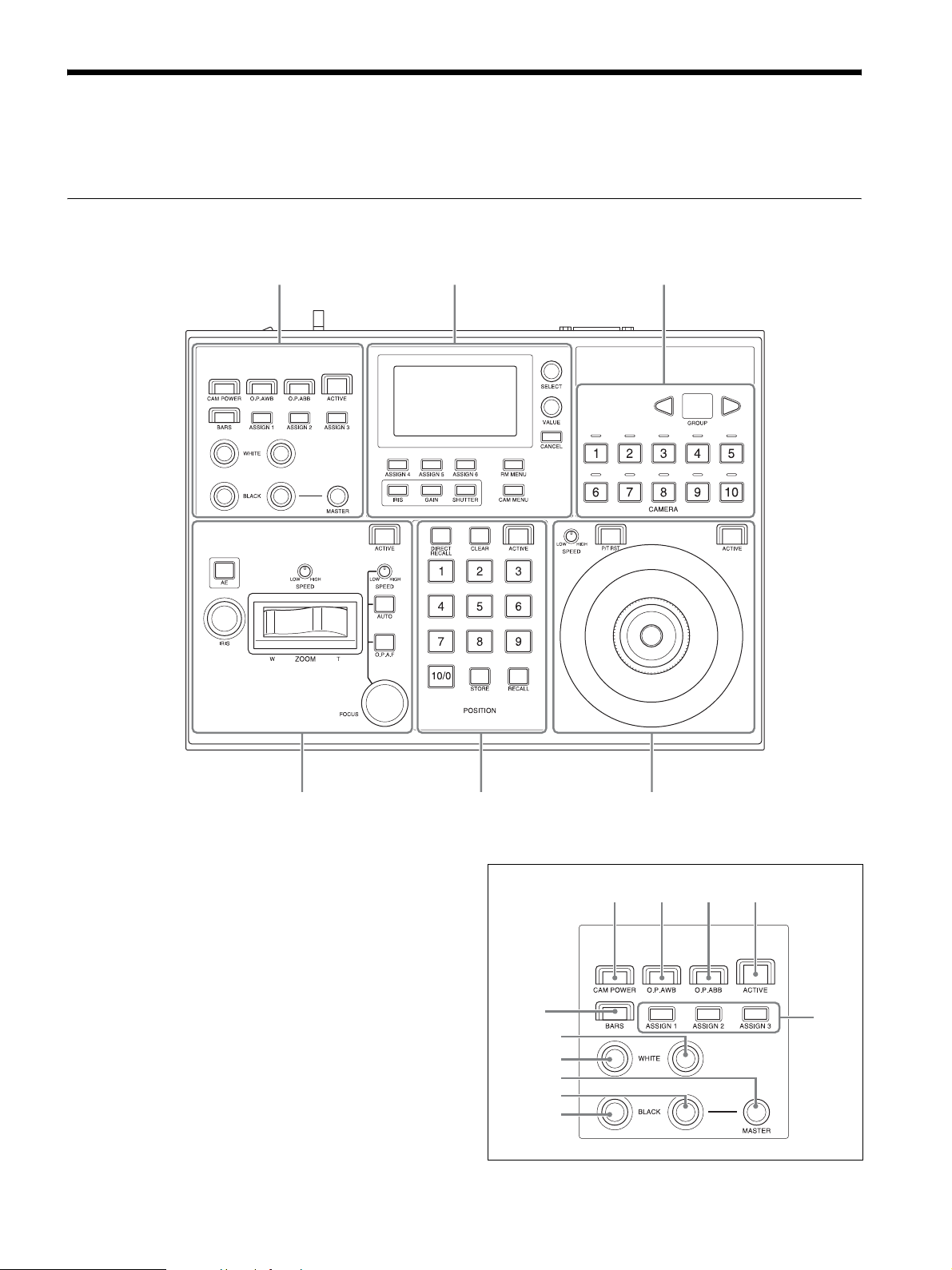
Location and Function of Parts
The functions controlled by the buttons and knobs vary depending on the target camera to control. For details, see
“Function of Buttons/Knobs in Each Block by Camera Model” (page 41).
Top
Color adjustment
block (page 5)
Menu control
block (page 6)
Camera selection
block (page 7)
Lens control block
(page 7)
Color adjustment block
Use to perform color adjustments on a camera.
Select the target camera to adjust the color.
The color adjustment block is enabled when the
7 ACTIVE button is lit.
For details about selecting the target camera, see
“Selecting a Camera” (page 27).
Preset memory control
block (page 8)
5
3
2-b
2-a
1-c
1-b
1-a
Joystick control block
(page 9)
654
7
8
Page 6
A 1-a R-BLACK knob
1-b B-BLACK knob
1-c MASTER BLACK knob
Adjusts the R black, B black, and master black of
the target camera.
For details, see “Adjusting the black balance”
(page 33).
B 2-a R-WHITE knob
2-b B-WHITE knob
Sets the R gain and B gain of the target camera, and
adjusts the white balance.
For details, see “Adjusting the white balance”
(page 32).
C BARS button
Toggles the color bars output of the target camera
on/off.
When the button is turned on (button is lit yellow),
color bars output is turned on.
When the button is turned off (button is not lit),
color bars are not output.
D CAM POWER button
Toggles the power supply of the target camera on/
off (standby).
When the button is turned on (button is lit green),
the target camera is turned on.
When the button is turned off (button is not lit), the
target camera is turned off (standby).
H ASSIGN 1 button, ASSIGN 2 button, ASSIGN 3
button
Executes functions assigned to each button on the
target camera.
In this version, the following functions have been
assigned, and cannot be changed.
Button name Assigned function
ASSIGN 1 Perform backlight compensation on the
target camera. For details, see
“Backlight compensation” (page 32).
ASSIGN 2 Perform flicker compensation on the
target camera. For details, see “Flicker
compensation” (page 32).
ASSIGN 3 Display the iris, gain, shutter speed, and
zoom position settings of the target
camera on the LCD panel. For details,
see “Checking Camera Settings Status
(Status Display)” (page 38).
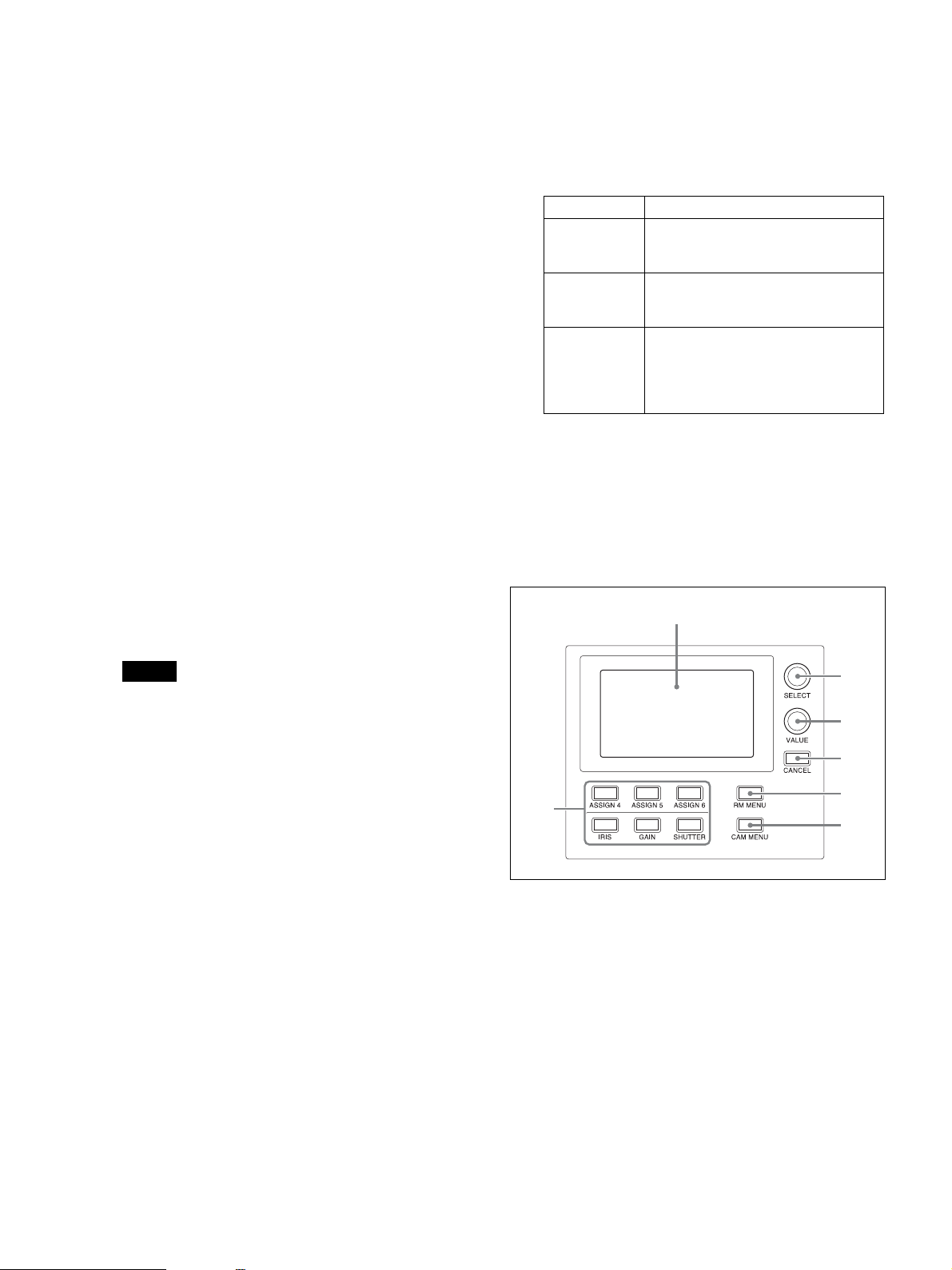
Menu control block
Comprises buttons and knobs you use to set and execute
functions, and to change settings on the target camera
using menu operations.
For details about menu operations, see “Menu
Operations” (page 12).
2
Note
When controlling more than one camera, the
camera on/off operation is determined by the
CONFIG >RM SETUP >CAM POWER setting in
the RM menu. For details, see “CAM POWER”
(page 46).
E O.P.AWB (one-push auto white balance) button
Executes one-push auto white balance adjustment
on the target camera.
For details, see “To adjust the white balance
automatically” (page 32).
F O.P.ABB (one-push auto black balance) button
Executes one-push auto black balance adjustment
on the target camera.
For details, see “To adjust the black balance
automatically” (page 33).
G ACTIVE button
Enables/disables the color adjustment block.
When the button is turned on (button is lit), the
color adjustment block becomes enabled.
When the button is turned off (button is not lit), the
color adjustment block becomes disabled.
3
4
5
6
1
7
A FUNCTION menu buttons
When a button is pressed, the item and setting of the
function assigned to the button is displayed on the
LCD panel, and the setting can be changed using
the VALUE knob.
The IRIS, GAIN, and SHUTTER button operations
are enabled when the buttons are lit blue.
For details about operation, see “Setting Specific
Functions using Shortcuts (FUNCTION Menu)”
(page 37).
IRIS button: Press this button to display the iris
value settings screen for the camera on the LCD
panel.
6
Page 7
GAIN button: Press this button to display the gain
value settings screen for the camera on the LCD
panel.
SHUTTER button: Press this button to display the
shutter speed value settings screen for the
camera on the LCD panel.
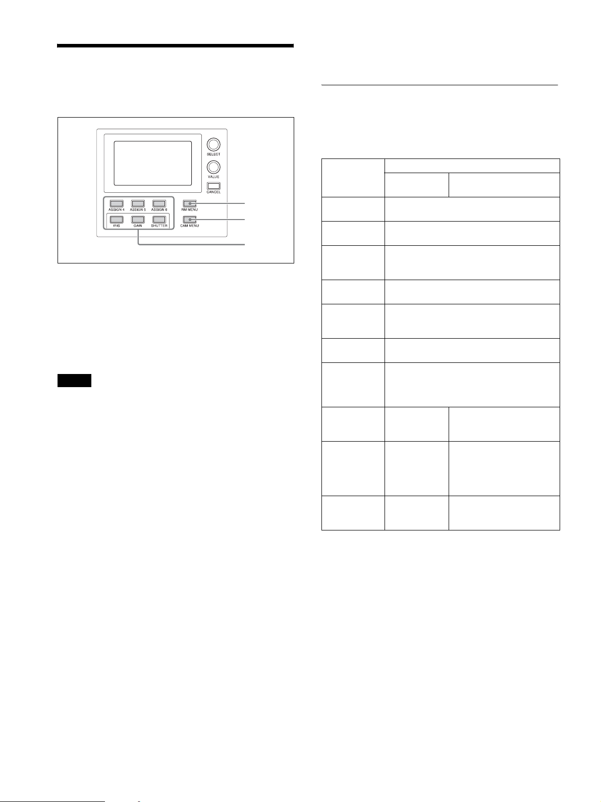
ASSIGN 4 button, ASSIGN 5 button, ASSIGN 6
button: Press these buttons to display the
corresponding setup item and setting of the
function assigned to each button on the LCD
panel.
In this version, the following functions have
been assigned, and cannot be changed.
Button name Assigned menu item
ASSIGN 4 Sets DETAIL LEVEL on the target
camera.
ASSIGN 5 Sets KNEE POINT on the target
camera.
ASSIGN 6 Sets AE LEVEL on the target camera.
For details about menu operations, see “Menu
Operations” (page 12).
G CAM MENU button
Press and hold this button to display the setup menu
of the camera on the monitor output of the camera.
Nothing is displayed on the LCD panel of the unit.
For details about operation, see “Operating the
Camera Setup Menu from the Unit (Camera Menu
Operation Mode)” (page 35).
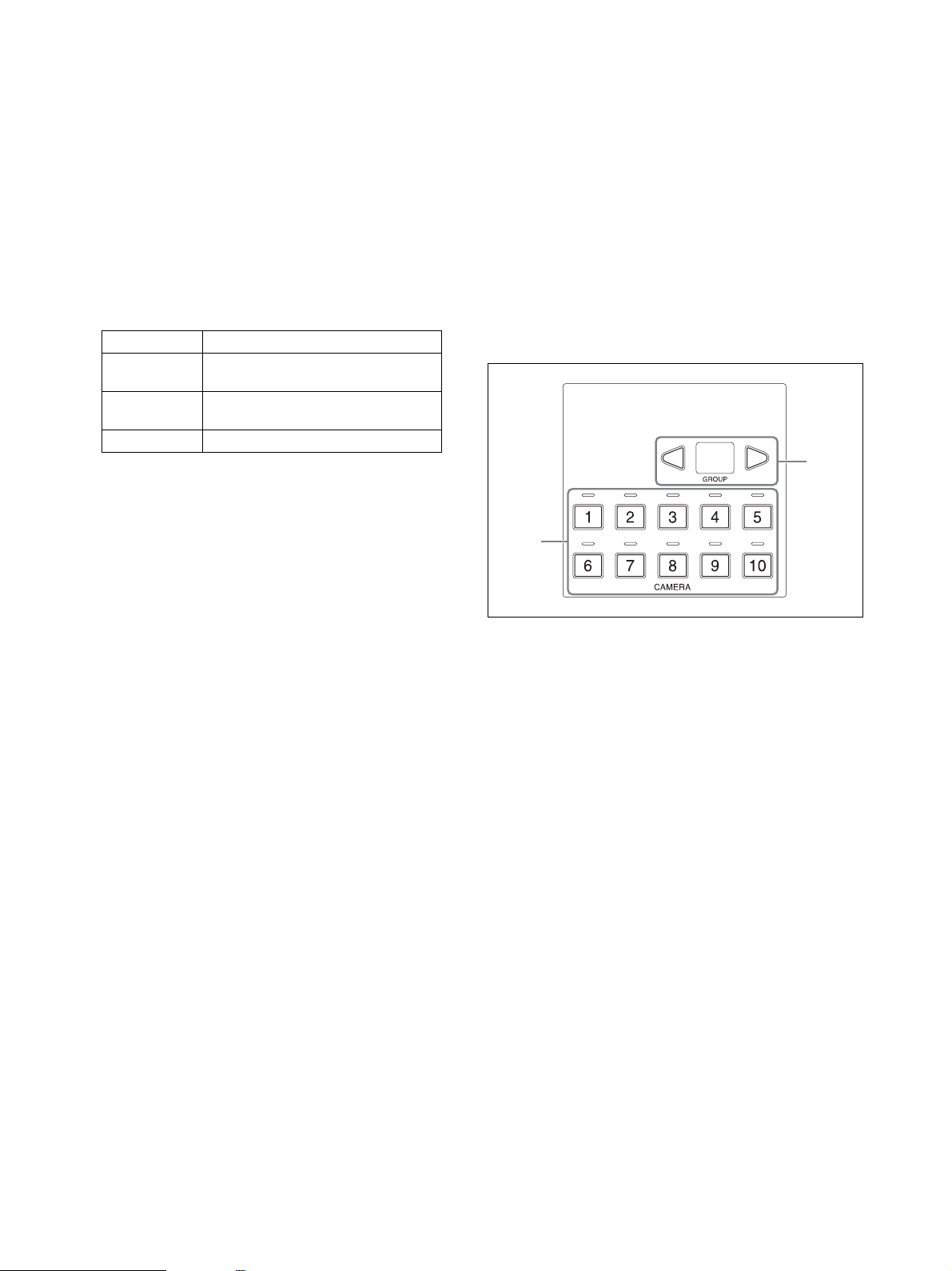
Camera selection block
Use to select the target camera to control.
When using LAN connection, the unit can control up to
100 cameras.
When using serial connection, the unit can control up to
7 cameras.
2
B LCD panel
Displays the RM menu, FUNCTION menu, and
preset memory numbers.
• For details about menu operations, see “Menu
Operations” (page 12).
• For details about the RM menu, see “RM Menu
List” (page 43).
• For details about the FUNCTION menu, see
“Setting Specific Functions using Shortcuts
(FUNCTION Menu)” (page 37).
• For details about preset numbers, see “Storing the
Camera Status (Preset Function)” (page 34).
C SELECT knob and button
Use to select menu items.
For details about menu operations, see “Menu
Operations” (page 12).
D VALUE knob and button
Use to select the settings of menu items.
For details about menu operations, see “Menu
Operations” (page 12).
E CANCEL button
Use to move from a lower level to a higher level in
the hierarchy for menu items that have a multi-level
hierarchy.
1
A CAMERA 1 to CAMERA 10 buttons
Selects the target camera from within a group.
For details about selecting the target camera, see
“Selecting a Camera” (page 27).
B GROUP LEFT button, group number display,
GROUP RIGHT button
Select the target camera group using the GROUP
LEFT button and GROUP RIGHT button. The
number of the selected group is displayed in the
group number display.
Group numbers are used with LAN connections.
For details about selecting a group, see “Selecting a
Camera” (page 27).
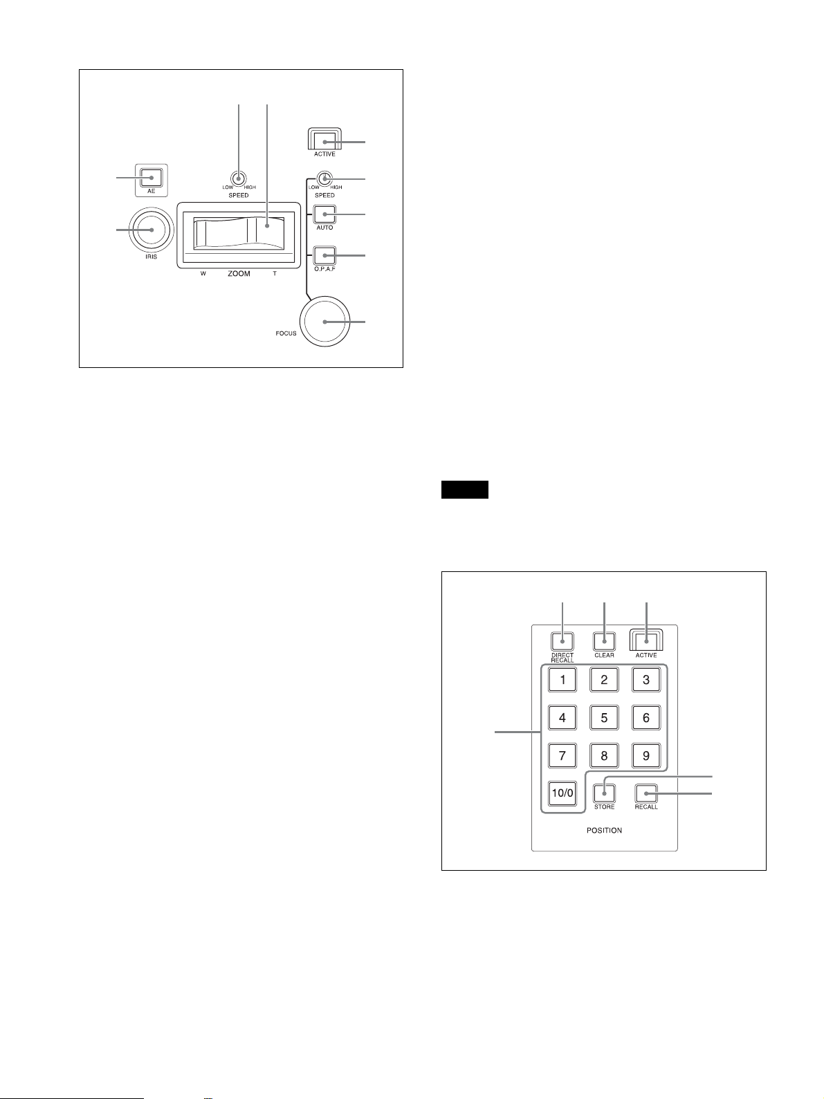
Lens control block
Use to control the lens (adjustment and settings) of the
target camera.
The lens control block is enabled when the 5 ACTIVE
button is lit. Note that the ZOOM SPEED knob is always
enabled.
F RM MENU button
Press this button to display the setup menu of the
unit on the LCD panel.
For details about menu operations, see “Menu
Operations” (page 12).
7
Page 8
3 4
5
G AUTO FOCUS mode button
Switches between automatic (button is lit) and
manual (button is not lit) focus adjustment mode on
the target camera.
For details, see “To adjust the focus automatically”
(page 31).
2
1
A IRIS knob
Adjusts the iris of the target camera.
For details, see “To adjust the exposure manually”
(page 31).
B AE button
Switches the exposure mode of the target camera.
When the button is turned on (button is lit), auto
adjustment mode is selected. When the button is
turned off (button is not lit), the exposure mode set
in the RM menu is selected.
For details, see “To adjust the exposure
automatically” (page 31).
6
7
8
9
H O.P.A.F (one-push auto focus) button
Press during manual focus adjustment mode to
execute one-push auto adjustment.
For details, see “One-push auto focus during
manual focus adjustment” (page 31).
I FOCUS adjustment knob
Adjusts the focus of the target camera manually.
For details, see “To adjust the focus manually”
(page 31).
Preset memory control block
Use to execute the Preset function for storing and
recalling camera status (such as pan, tilt, zoom position
settings) in internal memory on the camera.
The preset memory control block is enabled when the
4 ACTIVE button is lit.
Note
The number of presets varies depending on the model
and firmware version of the camera. For details, refer to
the Operating Instructions supplied with the camera.
2 3 4
C ZOOM SPEED knob
Sets the speed of zoom operations.
For details, see “To control the zoom using the
ZOOM lever on the lens control block” (page 30).
D ZOOM lever
Controls the zoom operation of the target camera.
For details, see “To control the zoom using the
ZOOM lever on the lens control block” (page 30).
E ACTIVE button
Enables/disables the lens control block.
When the button is pressed, turning it on (button is
lit), the lens control block becomes enabled.
When the button is turned off (button is not lit), the
lens control block becomes disabled.
F FOCUS SPEED knob
Sets the focus speed when adjusting the focus
manually.
For details, see “To adjust the focus manually”
(page 31).
1
5
6
A PRESET 1 button to PRESET 10/0 button
Use to enter the number (preset number) for
registering and recalling a preset camera status.
For details, see “Storing the Camera Status (Preset
Function)” (page 34).
8
Page 9

B DIRECT RECALL button
Recalls a preset stored in the target camera. Direct
recall mode is enabled when the button is lit. Press
PRESET 1 to PRESET 10/0 to recall the stored
settings immediately.
For details, see “Storing the Camera Status (Preset
Function)” (page 34).
C CLEAR button
Clears the currently entered preset number.
D ACTIVE button
Enables/disables operation of the preset memory
control block.
When the button is turned on (button is lit), the
preset memory control block becomes enabled.
When the button is turned off (button is not lit), the
preset memory control block becomes disabled.
E STORE button
Stores the camera status in the internal memory of
the camera for the specified preset number.
For details, see “Storing the Camera Status (Preset
Function)” (page 34).
Controls the pan, tilt, and zoom operation of the
target camera.
Pan/tilt: Incline the joystick left/right to rotate the
camera counterclockwise/clockwise (pan left/
right), incline the joystick forward/backward to
tilt the camera up/down. The panning/tilting
speed changes according to the angle at which
you incline the joystick. Movement stops when
the joystick returns to the center position
(position the joystick returns to after removing
your hand).
Zoom: Turn the ZOOM ring on the upper part of
the joystick clockwise to make the subject larger
(zoom in). Turn it counterclockwise to make the
subject smaller (zoom out).
A-a Joystick button
Press and hold to return the orientation of the
camera to face the front.
A-b ZOOM ring
Controls the zoom.
For details, see “To control the zoom using the
ZOOM ring on the top of the joystick” (page 30).
F RECALL button
Recalls a preset stored in the target camera.
For details, see “Recalling stored status” (page 34).
Joystick control block
Use to control the pan, tilt, and zoom of the target
camera using a joystick.
The joystick control block is enabled when the
4 ACTIVE button is lit.
Select the target camera to control the pan, tilt, and zoom
using a joystick.
For details about camera pan, tilt, and zoom operations,
see “Pan and tilt control” (page 29) and “Zoom control”
(page 30).
2 3 4
1
1
1
B PAN-TILT SPEED knob
Adjusts the speed of pan/tilt operations in response
to the joystick.
For details, see “To adjust the pan/tilt speed”
(page 29).
C P/T RST (pan/tilt reset) button
Press the button to reset the pan/tilt position of the
target camera.
D ACTIVE button
Enables/disables operation of the joystick control
block.
When the button is turned on (button is lit),
operation of the joystick control block becomes
enabled.
When the button is turned off (button is not lit),
operation of the joystick control block becomes
disabled.
A Joystick
9
Page 10
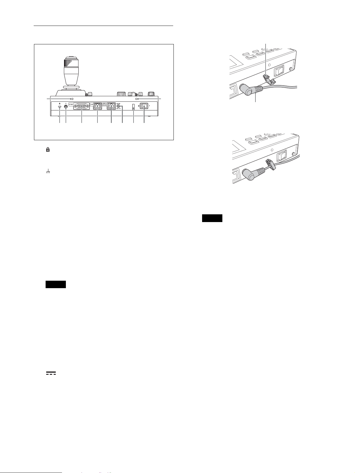
Rear
3 4 5 7 812
6
2 Connect an AC adapter.
Cord clamper
9
A Anti-theft wire attachment point
Attach a wire to prevent theft.
B Ground connection
C GPI I/O connector
Used as a tally input from an external device or as a
contact output connector of the selected camera
number.
D LAN (network) connector (RJ-45)
Use for LAN connection.
Connect a LAN hub (10BASE-T/100BASE-TX)
using a LAN cable (category 5 or higher).
When a link is established, the green indicator
lights, and it blinks during communication. For
100BASE-TX connections, the yellow indicator
lights.
Notes
• For safety, do not connect the connector for
peripheral device wiring that might have
excessive voltage to this port. Follow the
instructions for this port.
• When you connect the LAN cable of the unit to
peripheral device, use a shielded-type cable to
prevent malfunction due to radiation noise.
9
Cord of the AC adapter
3 Thread the cord of the AC power adapter
through the cord clamper, then close the lock.
H Power switch
Turns the power ^ (on) and 1 (off).
Note
When the unit is mounted in a console desk, turn
the power on/off using the main power supply of
the console desk.
I Screw holes
Mounting points available for use when not
mounting the unit on a flat surface.
Screw holes are provided on all sides, with the
screw holes on the front, left, and right sides
protected by covers (six locations).
E VISCA RS-422 connector (RJ-45)
Used for VISCA RS-422 serial connection.
F 12V! (DC power supply input)
connector
Connect to an AC power adapter.
G Cord clamper
Clamp the cord of the AC power adapter to prevent
the cord from being pulled out of the unit.
1 Release the lock of the cord clamper.
10
Page 11
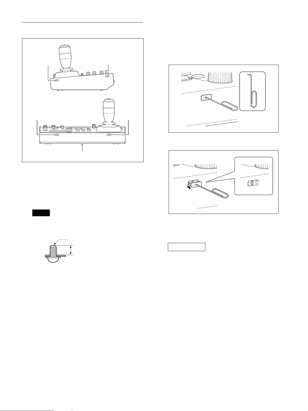
Side / front
2
1
1 1
A Screw hole protective covers
When mounting the unit on other than a flat surface,
remove the screw hole protective covers and secure
the unit in place with screws.
There are a total of six covers on the front, left, and
right sides.
1
Removing the screw hole protective covers
1
Bend the tip of a thin rod about 2 mm, and insert it
into the hole of the screw hole protective cover.
Use a paper clip or other object with a diameter of
about 1 mm.
2
Pull the screw hole protective covers straight out.
Note
• Use standard size screws with the following
dimensions.
M3 screw
4
4=6 mm to 10 mm
• Do not overtighten the screws. Overtightening
the screws may damage the unit.
• Store the removed screw hole protective covers in
a safe location.
• Using screws other than 6 mm to 10 mm may
result in faulty installation or damage to the
interior of the machine, resulting in malfunction.
B Ratings label (bottom)
Displays the model name and electrical ratings
information.
IMPORTANT
The nameplate is located on the bottom.
11
Page 12
Menu Operations
3
For details, see “Setting Specific Functions using
Shortcuts (FUNCTION Menu)” (page 37).
The menu control block is used to configure the device
settings and camera settings.
1
2
One of the three menus (RM menu, camera menu, or
FUNCTION menu) is always selected.
When the RM menu or FUNCTION menu is selected,
the menu items and settings are displayed on the LCD
panel.
When the camera menu is selected, nothing is displayed
on the LCD panel.
Note
Except for the OPERATION menu, return to the top
menu when operating a camera. If a lower-level menu is
displayed, cameras cannot be operated.
A RM menu
This menu is used to configure picture quality
adjustments and compensation functions on target
cameras, configure the unit, execute/configure auto
assign functions on cameras, and for performing
configuration from a connected setup PC.
When the RM menu button is turned on, RM menu
setup mode is invoked and the top menu is
displayed on the LCD panel.
For details, see “RM Menu List” (page 43).
B Camera menu
Turns the superimposed output of the camera setup
menu on the camera image on/off. When turned on,
operation of the setup menu on the camera using the
knobs and buttons on the menu control block and
the joystick is enabled.
For details, see “Operating the Camera Setup Menu
from the Unit (Camera Menu Operation Mode)”
(page 35).
Basic menu operations
Buttons and knobs used for RM menu
operations
Operation Buttons and knobs used
OPERATION
menu
Display the top
menu.
Select a top
menu item.
Confirm the
menu item
selection.
Select a setup
menu item.
Confirm the
setup menu
item selection.
Select a setup
menu sub item.
Change the
setting of the
setup menu sub
item.
Confirm the
changed
setting.
Save settings. Saved on the
Go back one
level in the
menu.
*1 A confirmation message appears for settings that display an
EXEC item.
*2 If the CANCEL button is pressed before attempting to save,
the menu display goes back one level and restores the
existing setting.
*3 For details about items saved with a preset number, refer to
the operating instructions of each camera.
Press the RM MENU button.
Turn the SELECT knob.
Press the SELECT button.
Turn the SELECT knob.
Press the SELECT button.
Turn the SELECT knob.
Turn the VALUE knob.
Confirmation
not required.
camera using
the camera
preset memory
function.
Press the
CANCEL
button.
*3
CONFIG, AUTO IP SETUP,
or MAINTENANCE menu
Press the VALUE button.
Save on the unit.
Press the CANCEL
*2
button.
*1
C FUNCTION menu
This menu is used to configure functions assigned
to buttons using shortcuts.
12
Page 13
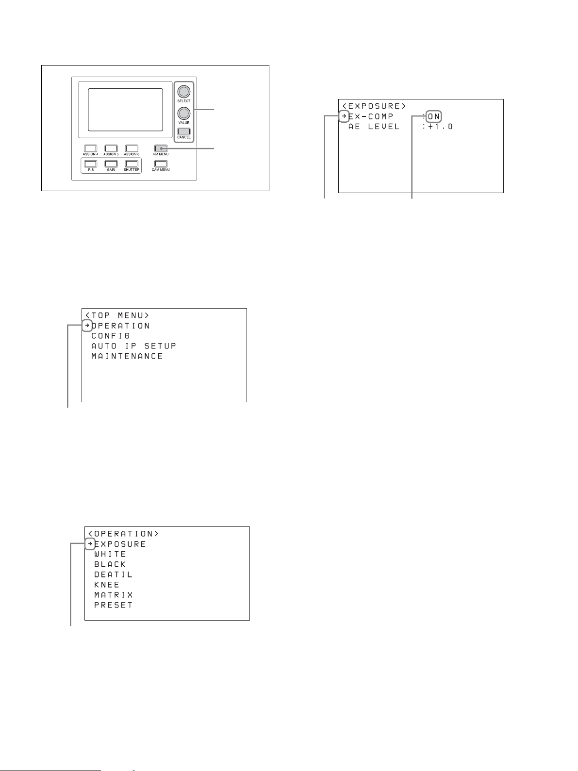
Typical RM menu operation
2~7
1
The cursor moves up/down as the SELECT knob is
turned.
7
Turn the VALUE knob to select the setting.
1
Press the RM MENU button, turning it on (button
is lit yellow).
The RM menu top menu appears.
2
Turn the SELECT knob to move the cursor to the
desired item to set.
The cursor moves up/down as the SELECT knob is
turned.
Cursor
3
Press the SELECT button.
The menu for the selected item appears.
4
Turn the SELECT knob to move the cursor to the
desired setup menu item.
The cursor moves up/down as the SELECT knob is
turned.
Cursor Selected setting
To configure items in other menus
Press the CANCEL button to return to the parent item in
the menu, and then use the same procedure.
To save a setting in the unit
Press the VALUE button after adjusting the setting.
Cursor
5
Press the SELECT button.
The selected menu item and its setup items appear.
6
Turn the SELECT knob to move the cursor to the
desired item.
13
Page 14
Getting Started
VISCA over IP (LAN) connection
VISCA over IP (LAN) connection is configured using
the following sequence.
Connections
You can connect the unit to cameras using VISCA over
IP (LAN) connection or VISCA RS-422 (serial)
connection.
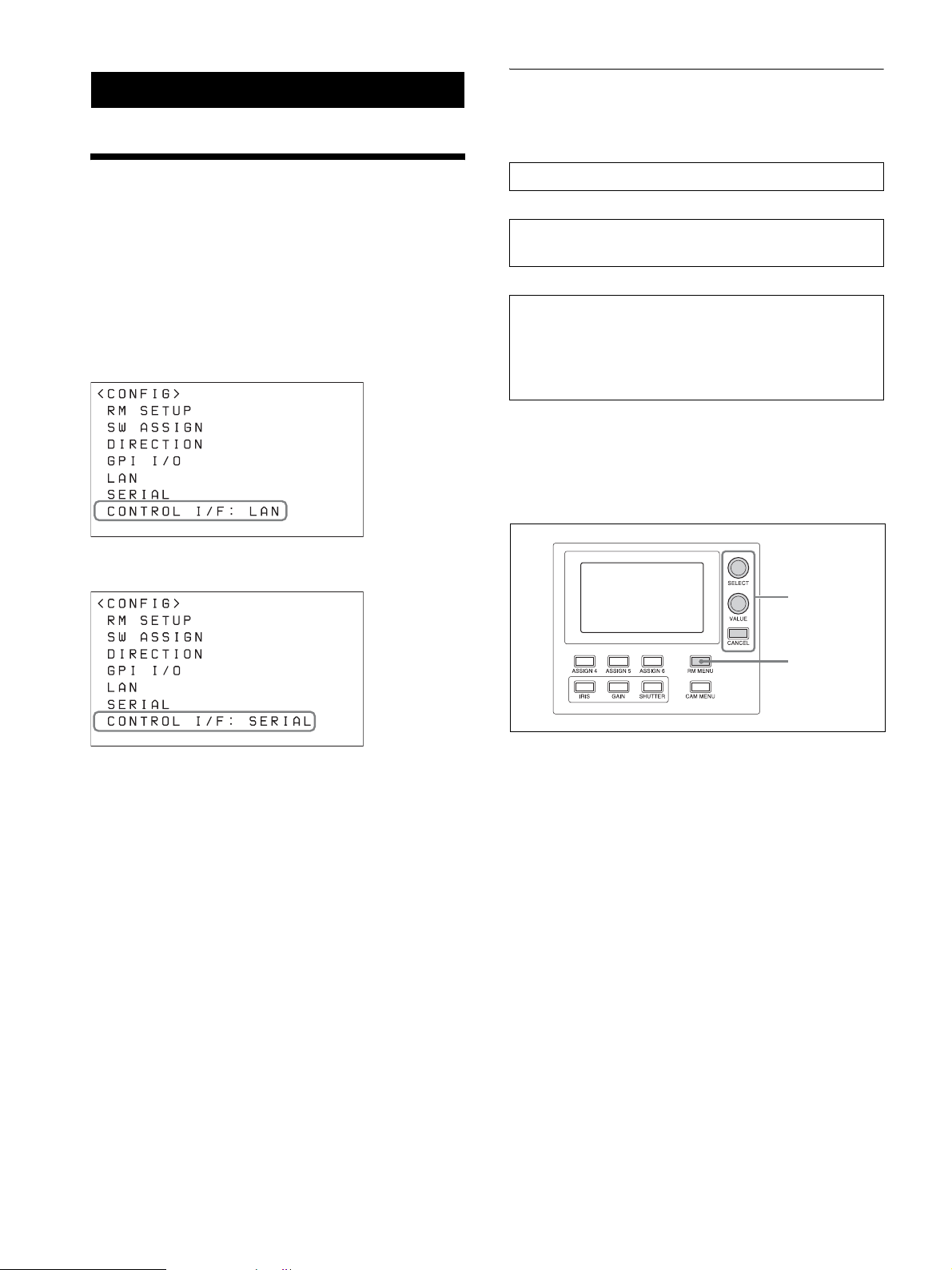
The connection method that is used is displayed at the
bottom of the CONFIG menu item in the RM menu.
VISCA over IP (LAN) connection
VISCA RS-422 (serial) connection
Setting the IP address of the unit (page 14)
m
Connecting remote controllers, cameras, and setup PC
using LAN connection (page 16)
m
Assigning cameras (page 17)
• Assignment using AUTO IP SETUP >SETUP IP
(page 17)
• Assignment using AUTO IP SETUP >ASSIGN
CAM (page 18)
Setting the IP address of the unit
Before connection, set the IP address of the unit.
The setting is configured using CONFIG >LAN in the
RM menu.
2~11
• For details about VISCA over IP (LAN) connection,
see “VISCA over IP (LAN) connection” (page 14).
• For details about VISCA RS-422 (serial) connection,
see “VISCA RS-422 (serial) connection” (page 21).
For details about connections, refer to the operating
instructions supplied with the camera.
1
1
Press the RM MENU button, turning it on (button
is lit yellow).
The RM menu top menu appears.
2
Turn the SELECT knob to move the cursor to
CONFIG.
3
Press the SELECT button.
The CONFIG menu appears.
4
Turn the SELECT knob to move the cursor to LAN,
and press the SELECT button.
14
Page 15
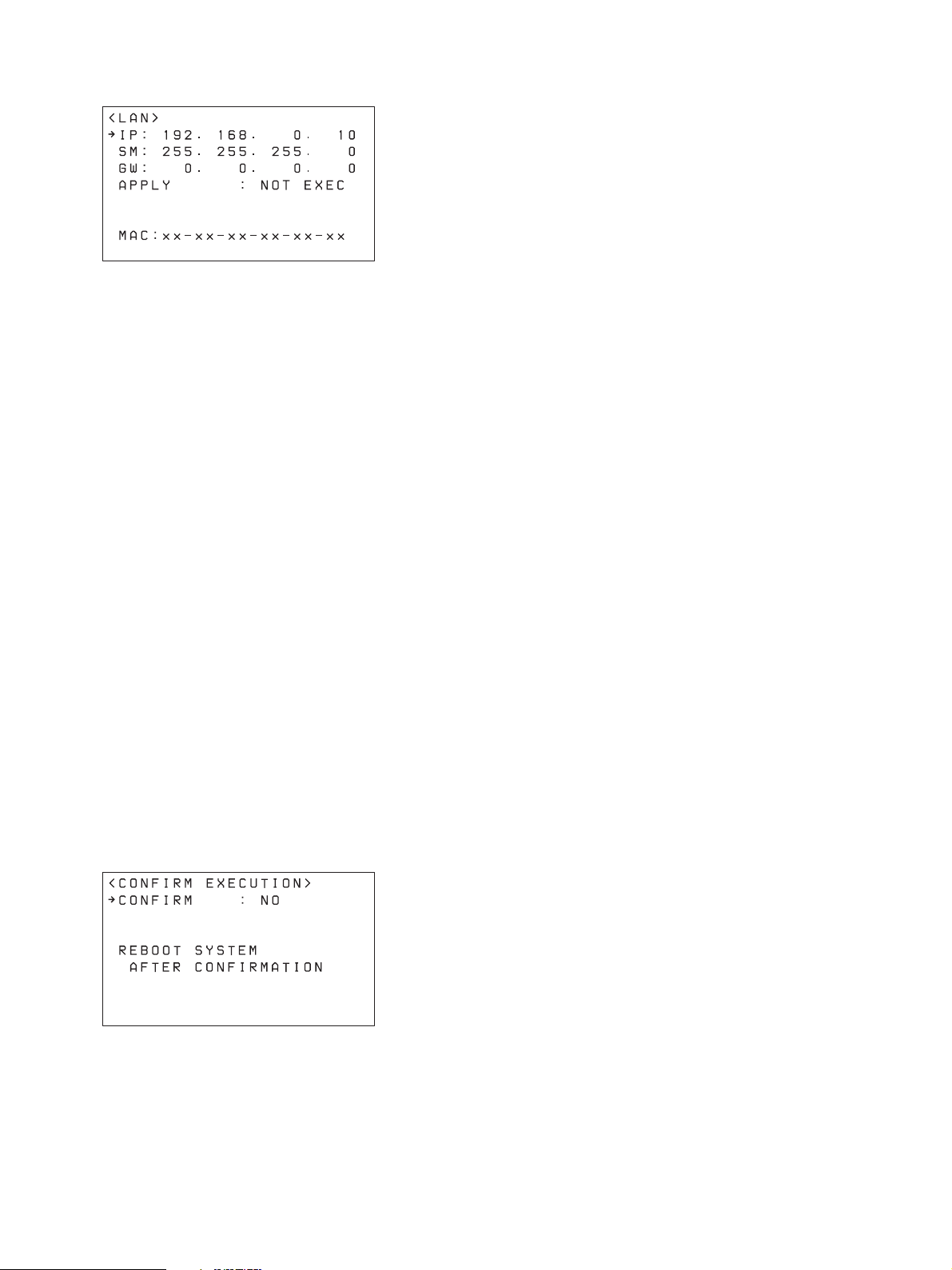
The LAN menu appears.
The MAC address is displayed at the bottom.
5
Turn the SELECT knob to move the cursor to IP.
6
Set the IP address using the SELECT knob and
VALUE knob/button.
The default setting is 192.168.0.10.
1 Turn the SELECT knob clockwise to move the
cursor to the first three digits (for example,
192).
IP:p192. 168. 0. 10
2 Turn the VALUE knob to set the value.
Turning clockwise increases the value, and
turning counterclockwise decreases the value.
3 Turn the SELECT knob to move to the next
number and repeat step 2 to set the other
numbers.
Upon rebooting, the IP address setting is
completed.
7
Set SM (subnet mask) and GW (default gateway
address) in the same way as described in steps 5 and
6.
8
When finished making all settings, move the cursor
to APPLY.
9
Turn the VALUE knob to change NOT EXEC to
EXEC, then press the VALUE button.
The following message appears, prompting you to
reboot the unit.
10
Turn the SELECT knob to move the cursor to
CONFIRM.
11
Turn the VALUE knob to change NO to YES, then
press the VALUE button.
The unit reboots automatically.
15
Page 16
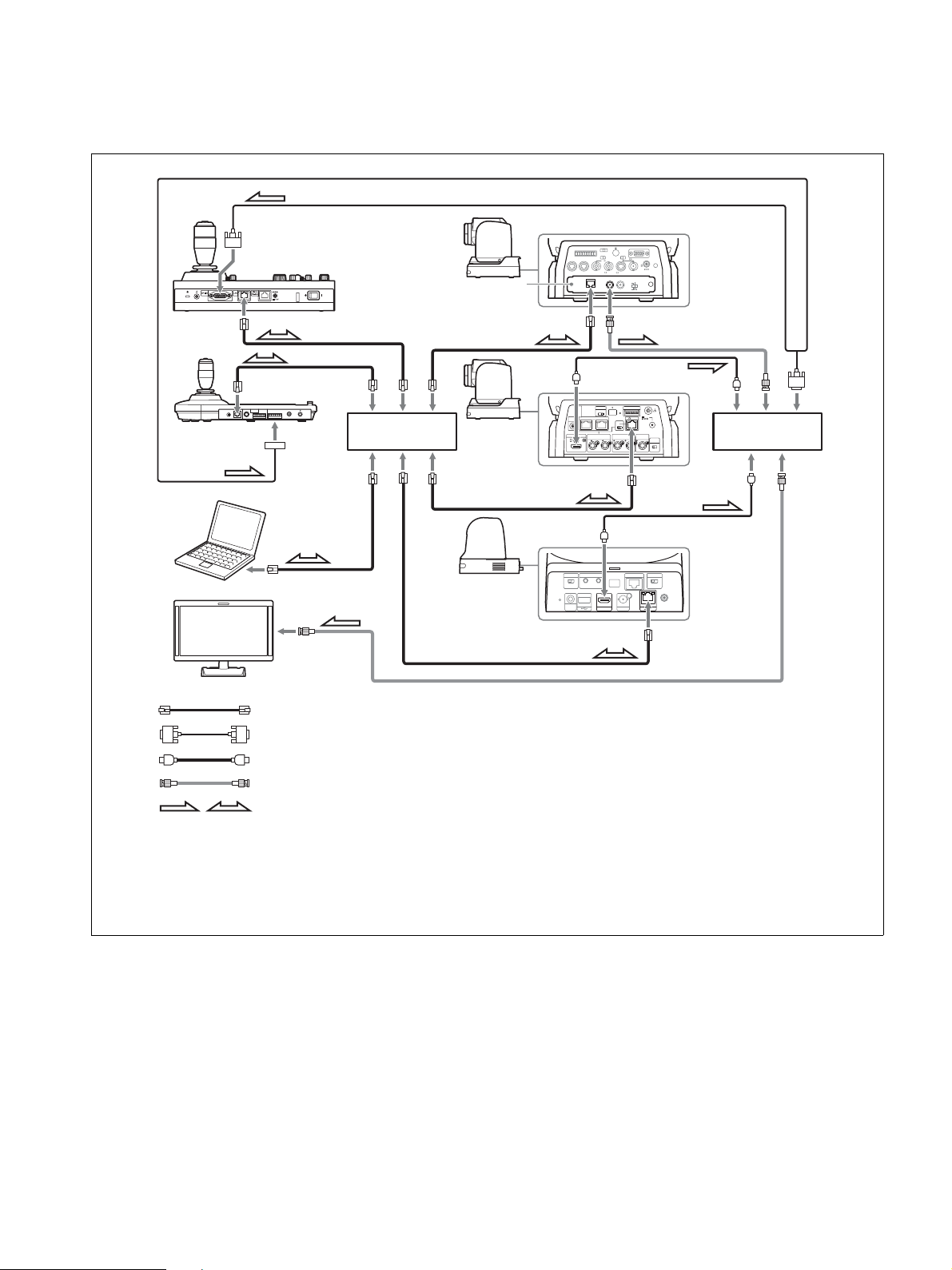
Connecting remote controllers, cameras, and setup PC using LAN connection
Connection example
BRC-H900
1 2 3
R
1 2 3 4 5 6 7 8 9
IR SELECT
VISCA RS-422
OFF ON HD SD
RGB/COMPONENT
75
EXT SYNC IN
VIDEO S VIDEO
IN VISCA RS-232 OUT SDI OUT
12
BRBK-IP10
SDI OUTLAN
BRC-X1000,
BRC-H800
IR SELECT
CAMERA SETUP
123
SYSTEM
VISCARS - 422 OUT
IN
SELECT
MONITOR OUTHDMI OUT
SDI 1 SDI 2
OSD
ON OFF
LINE OUT
SDI 1
SRG-360SHE
DC IN 12V
DATA MIX
OFF
ON
HD
SD
12V
LAN
EXT SYNC IN
SDI 2
TERMI NATION
ON OFF
Video switcher
RM-IP10
RM-IP500
BRBK-IP10 IP
control card
LAN
RS-422RS-232C
MODE
!
VISCA
*3
Switching hub
*1
MIC
Setup PC
RAUD RATE
SYSTEM
SELECT
RL
(PLUG IN POWER)
HDMI OUT SDI OUT
VISCA RS-422 IR SELECT
LAN
Video monitor
Remote control signal: LAN cable (category 5 or higher)
Tally/contact signal: Connection cable with D-sub 15-pin connectors
Video signal: HDMI cable
*2
*2
Video signal: Connection cable with BNC connectors
Signal flow
*1 For an example connection with a video switcher, see “Connection with a video switcher” (page 24).
*2 Use a connection cable designed for the switcher being used. For the specifications of the GPI I/O connector of
the unit, see “Pin assignments” (page 52).
*3 To connect the BRC-H900 using a LAN connection, a BRBK-IP10 IP control card must be installed. In addition,
use an IP control card with firmware version 2.1 or later.
1
Connect the LAN connector of the units and LAN
connector of the cameras using LAN cables.
You can connect up to 100 cameras and five remote
controllers on the same network.
• Connect the cameras, remote controllers, and PC
via switching hubs (10BASE-T or 100BASETX). Use on a network with significant packet
loss or delay may cause a malfunction. Use a
high-quality network.
2
To configure setting of the unit and cameras using
setup software, connect a PC to the same network.
• Use shielded-type LAN cables to prevent
malfunction that may result from radiation noise.
• Do not mix 10BASE-T and 100BASE-TX in the
network.
• The IP address of the unit is set to 192.168.0.10,
and the IP address of a camera and BRBK-IP10
• Use a LAN cable (category 5 or higher).
16
Page 17

IP control card is set to 192.168.0.100 by factory
default.
• Connecting stackable switching hubs in up to 2tier configuration is recommended to avoid
network delay.
Notes
3~
• Do not connect more than 100 cameras, five
remote controllers, and one setup PC across all
networks, even if controlling a camera that is on
a network of a different segment via a router. If
you connect more devices than this, problems
may occur, such as control delays or cameras are
operated incorrectly due to IP address
duplication.
• If you perform the setup from multiple PCs, the
settings may not be made correctly. Perform the
setup from one PC.
• Set the setup PC so that only the network that you
use is enabled.
• Do not connect cameras and remote controllers to
a public network.
3
Connect the cameras and remote controllers to AC
outlets using AC adapters and AC power cords.
The cameras pan/tilt automatically when power is
turned on.
Assigning cameras
Link the camera numbers, used for operating cameras
from the unit, with the cameras on the network. This is
called camera assignment.
A list of the assigned cameras is saved in the unit as a
camera table.
Camera numbers are sequential in each group, and are
selected using the GROUP buttons and CAMERA
number buttons of the camera selection block.
Camera assignments are performed using AUTO IP
SETUP >SETUP IP or AUTO IP SETUP >ASSIGN
CAM in the RM menu.
Note
Only cameras that are on the same segment as the
remote controller can be assigned using AUTO IP
SETUP.
Use the setup software to assign cameras on different
segments.
2
1
Check that the assigned camera is connected to the
network, and that the camera power is turned on.
2
Press the RM MENU button, turning it on (button
is lit yellow).
The RM menu top menu appears.
3
Turn the SELECT knob to move the cursor to
AUTO IP SETUP.
4
Press the SELECT button.
The AUTO IP SETUP menu appears.
5
Turn the SELECT knob to select SETUP IP or
ASSIGN CAM, and press the SELECT button.
Select one of the following methods, depending on
the type of camera assignment.
• For connections on a new network: “Assignment
using AUTO IP SETUP >SETUP IP” (page 17)
• For adding an assignment to an existing network:
“Assignment using AUTO IP SETUP >ASSIGN
CAM” (page 18)
Assignment using AUTO IP SETUP >SETUP
IP
This method detects cameras on the network, and
automatically assigns the IP address setting and
camera number for unregistered cameras.
Use this method when constructing a new network.
With this method, you specify the range of IP
addresses assigned to cameras by entering the start
address in [FROM] and the end address in [TO].
Set the range of IP addresses for assignment so that
they are in the same segment as the remote
controller.
Note
17
The same IP address as a remote controller cannot
be set.
The subnet mask (SM) and gateway address (GW)
of the camera are assigned the same settings as the
remote controller.
Page 18

1 Turn the SELECT knob to move the cursor to
IP under [FROM].
2 Set the start value of the IP addresses to assign
to newly registered cameras.
Turn the SELECT knob clockwise to move the
cursor to the first three digits (for example,
192).
IP: p192. 168. 0. 100
qs Check the camera assignment result using
AUTO IP SETUP >CAMERA TABLE in the
RM menu.
For details about displaying CAMERA
TABLE, see “To check the camera table”
(page 20).
Assignment using AUTO IP SETUP
>ASSIGN CAM
This method is used to assign camera numbers to
cameras that already have a configured IP address.
With this method, you can specify the group
number and camera number of the camera selection
button from which to start assignments.
For details about the group number and camera
number, see “Selecting a Camera” (page 27).
Note
3 Turn the VALUE knob to set the value.
Turning clockwise increases the value, and
turning counterclockwise decreases the value.
4 Turn the SELECT knob to move to the next
number and repeat step 3 to set the other
numbers.
5 Turn the SELECT knob to move the cursor to
IP under [TO].
6 Set the end value of the IP addresses to assign
to newly registered cameras.
Turn the SELECT knob clockwise to move the
cursor to the first three digits (for example,
192).
IP:p192. 168. 0. 199
7 Turn the VALUE knob to set the value.
Turning clockwise increases the value, and
turning counterclockwise decreases the value.
8 Turn the SELECT knob to move to the next
number and repeat step 7 to set the other
numbers.
9 When finished making all settings, turn the
SELECT knob to move the cursor to SETUP IP.
0 Turn the VALUE knob to change NOT EXEC
to EXEC, then press the VALUE button.
A confirmation message appears.
Only cameras within the same segment can be
assigned.
1 Turn the SELECT knob to move the cursor to
GROUP NUM.
Set the group number for which to begin
assignment.
2 Turn the VALUE knob to set the value.
Turning clockwise increases the value, and
turning counterclockwise decreases the value.
3 Turn the SELECT knob to move the cursor to
CAMERA NUM.
Set the camera number for which to begin
assignment.
4 Turn the VALUE knob to set the value.
Turning clockwise increases the value, and
turning counterclockwise decreases the value.
5 When finished making all settings, turn the
SELECT knob to move the cursor to KEEP IP.
6 Turn the VALUE knob to change NOT EXEC
to EXEC, then press the VALUE button.
A confirmation message appears.
qa Turn the VALUE knob to change NO to YES,
then press the VALUE button.
18
Page 19

7 Turn the VALUE knob to change NO to YES,
then press the VALUE button.
To add cameras
Perform the configuration again using AUTO IP SETUP
>SETUP IP or AUTO IP SETUP >ASSIGN CAM.
Assigned cameras are added to the bottom of the camera
table.
For details, see “Assignment using AUTO IP SETUP
>SETUP IP” (page 17) or “Assignment using AUTO IP
SETUP >ASSIGN CAM” (page 18).
To clear the camera table
You can clear all the camera information stored in the
camera table.
6
Turn the VALUE knob to change NO to YES, then
press the VALUE button.
To swap camera numbers
You can change the camera numbers after IP addresses
have been configured automatically.
1
Press the RM MENU button, turning it on (button
is lit yellow).
The RM menu top menu appears.
2
Turn the SELECT knob to move the cursor to
AUTO IP SETUP.
3
Press the SELECT button.
The AUTO IP SETUP menu appears.
4
Turn the SELECT knob to select SWAP CAM, and
press the SELECT button.
The SWAP CAM menu appears.
Note
The camera table cannot be restored once it has been
cleared.
1
Press the RM MENU button, turning it on (button
is lit yellow).
The RM menu top menu appears.
2
Turn the SELECT knob to move the cursor to
AUTO IP SETUP.
3
Press the SELECT button.
The AUTO IP SETUP menu appears.
4
Turn the SELECT knob to select CLEAR TABLE,
and press the SELECT button.
The CLEAR TABLE menu appears.
5
Turn the VALUE knob to change NOT EXEC to
EXEC, then press the VALUE button.
A confirmation message appears.
This screen is used to swap the camera information
of CAMERA A and CAMERA B.
5
Turn the SELECT knob to move the cursor to
CAMERA A.
6
Turn the VALUE knob to change the camera group
number and the camera number of the camera to
swap.
pCAMERA A : 01-01
Camera number
Group number
The IP address and MAC address of the
corresponding camera are displayed in IP and
MAC, respectively.
7
Turn the SELECT knob to move the cursor to
CAMERA B.
19
8
Enter the camera group number and the camera
number of the camera to swap using the same
procedure for CAMERA A.
Page 20

9
Turn the SELECT knob to move the cursor to
SWAP A<=>B.
pSWAP A<=>B : NOT EXEC
10
Turn the VALUE knob to change NOT EXEC to
EXEC, then press the VALUE button.
A confirmation message appears.
11
Turn the VALUE knob to change NO to YES, then
press the VALUE button.
12
Check the result using AUTO IP SETUP
>CAMERA TABLE in the RM menu.
To check the camera table
You can check all the camera information in the camera
table.
LOWER display UPPER display
<CAMERA TABLE>
p
GROUP NUM : 01-LOWER
CAM INFO : IP ADD
01:192.168. 0.100
02:192.168. 0.101
03:192.168. 0.102
04:192.168. 0.103
05:192.168. 0.104
<CAMERA TABLE>
p
GROUP NUM : 01-UPPER
CAM INFO : IP ADD
06:192.168. 0.105
07:192.168. 0.106
08:192.168. 0.107
09:192.168. 0.108
10:192.168. 0.109
You can turn the SELECT knob to move the cursor
to CAM INFO, then turn the VALUE knob to
switch the camera information between IP ADD
and MAC ADD display.
pCAM INFO : IP ADD
IP ADD or MAC ADD
In IP ADD display, the IP addresses of the cameras
are displayed.
In MAC ADD display, the MAC addresses of the
cameras are displayed.
MAC address display
1
Press the RM MENU button, turning it on (button
is lit yellow).
The RM menu top menu appears.
2
Turn the SELECT knob to move the cursor to
AUTO IP SETUP.
3
Press the SELECT button.
The AUTO IP SETUP menu appears.
4
Turn the SELECT knob to select CAMERA
TABLE, and press the SELECT button.
The CAMERA TABLE menu appears.
The camera information for cameras 1 to 5 in group
1 are displayed on the screen.
You can check the camera information for other
cameras not displayed by turning the VALUE knob.
pGROUP NUM : 01-LOWER
LOWER or UPPER
Group number
The camera information for cameras 01 to 05 in a
group are displayed when LOWER is selected.
The camera information for cameras 06 to 10 in a
group are displayed when UPPER is selected.
20
Page 21

VISCA RS-422 (serial) connection
You can connect multiple cameras in a serial connection using the VISCA RS-422 connectors. In a serial connection, a
remote controller can control up to seven cameras. These cables support connection at distances of up to 1.2 km (3,937
feet).
Use a LAN straight cable for RS-422 connection using the RJ-45 connector.
Connecting remote controllers and cameras using serial connection
Connection example
For connection of a single camera to a single remote controller
Camera with RJ-45 connector
MIC
RL
(PLUG IN POWER)
HDMI OUT SDI OUT
VISCA RS-422 IR SELECT
LAN
RM-IP500
RAUD RATE
SYSTEM
SELECT
For connection of multiple cameras to a single remote controller
RM-IP500
SYSTEM
IN
SELECT
Camera
with RJ-45
connector
IR SELECT
123
VISCARS - 422 OUT
OSD
ON
MONITOR OUTHDMI OUT
SDI 1
SDI 1 SDI 2
OFF
LINE OUT
CAMERA SETUP
ON
23456781
SDI 2
12V
LAN
EXT SYNC IN
TERMI NATION
ON OFF
Camera
IN
with RJ-45
connector
IR SELECT
CAMERA SETUP
123
ON
23456781
SYSTEM
IN
VISCARS - 422 OUT
SELECT
MONITOR OUTHDMI OUT
SDI 1 SDI 2
12V
LAN
OSD
ON
OFF
LINE OUT
EXT SYNC IN
SDI 1
SDI 2
TERMI NATION
ON OFF
OUT IN OUT IN
Remote control signal: LAN straight cable (category 5 or higher)
Camera
with 9-pin
connector
1 2 3
R
1 2 3 4 5 6 7 8 9
IR SELECT
VISCA RS-422
OFF ON HD SD
75
IN VISCA RS-232 OUT SDI OUT
EXT SYNC IN
VIDEO S VIDEO
12
BRBK-IP10
SDI OUTLAN
DATA MIX
ON
HD
RGB/COMPONENT
OFF
SD
Camera
with RJ-45
connector
IR SELECT
CAMERA SETUP
123
ON
23456781
SYSTEM
IN
VISCARS - 422 OUT
DC IN 12V
SELECT
MONITOR OUTHDMI OUT
SDI 1 SDI 2
12V
LAN
OSD
ON
OFF
LINE OUT
EXT SYNC IN
SDI 1
SDI 2
TERMI NATION
ON OFF
Up to seven
cameras
Note
When connecting an SRG-360SHE in a serial connection, only one SRG-360SHE camera can be connected to a single
remote controller.
To connect multiple SRG-360SHE cameras or to mix with other model cameras, use the connection described in
“VISCA over IP (LAN) connection” (page 14).
21
Page 22

VISCA RS-422 connection diagram example
3rd to 7th camera
Camera with RJ-45 connector
VISCA RS-422 IN connector
(RJ-45)
TXD_IN
1
2
3
4
5
6
7
8
TXD_IN+
RXD_IN
GND
GND
RXD_IN+
NC
NC
-
-
2nd camera
Camera with RJ-45 connector
VISCA RS-422 OUT connector
(RJ-45)
RXD_OUT
1
RXD_OUT+
2
TXD_OUT
3
4
GND
5
GND
TXD_OUT
6
7
NC
8
NC
-
-
+
VISCA RS-422 IN connector
(RJ-45)
TXD_IN
TXD_IN+
RXD_IN
GND
GND
RXD_IN
NC
NC
-
-
+
1
2
3
4
5
6
7
8
RM-IP500
Remote Controller
VISCA RS-422 connector (RJ-45)
RXD_OUT
1
2
RXD_OUT+
3
TXD_OUT
4
GND
5
GND
6
TXD_OUT+
7
NC
8
NC
-
-
NC = No connection (not used)
1st camera
Camera with 9-pin connector
VISCA RS-422 connector
(connector block)
RXD_OUT
1
2
RXD_OUT+
3
TXD_OUT
4
TXD_OUT+
5
GND
6
RXD_IN
7
RXD_IN+
8
TXD_IN
9
TXD_IN+
-
-
-
-
22
Page 23
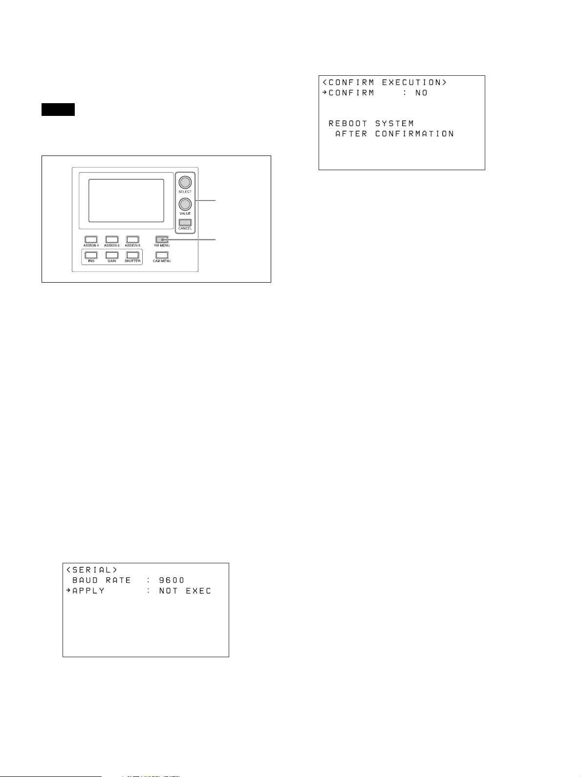
Configuring a serial connection
After cameras are connected correctly, select serial
connection using CONFIG >SERIAL in the RM menu,
set the baud rate, and assign camera addresses.
Note
If a connected camera is changed after completing the
configuration, the cameras must be configured again.
2~8
1
1
Press the RM MENU button, turning it on (button
is lit yellow).
The RM menu top menu appears.
connection or changing the baud rate, prompting
you to reboot the unit.
7
Turn the SELECT knob to move the cursor to
CONFIRM.
8
Turn the VALUE knob to change NO to YES, then
press the VALUE button.
The unit reboots automatically.
Upon rebooting, the serial connection setting is
completed.
2
Turn the SELECT knob to move the cursor to
CONFIG.
3
Press the SELECT button.
The CONFIG menu appears.
4
Turn the SELECT knob to move the cursor to
SERIAL, and press the SELECT button.
The SERIAL menu appears.
Set the baud rate, as required.
Turn the SELECT knob to move the cursor to
BAUD RATE, turn the VALUE knob, and select
9600 or 38400.
The default setting is 9600.
5
Turn the SELECT knob to move the cursor to
APPLY.
6
Turn the VALUE knob to change NOT EXEC to
EXEC, then press the VALUE button.
The following message appears after changing the
connection method from LAN connection to serial
23
Page 24

Connection with a video switcher
By connecting the tally output of a video switcher to the GPI I/O connector of the unit, the tally lamps of the unit light
up in unison with the switcher operation which you can use to switch the target camera to control.
The following diagram shows the connection with an MCX-500 Multi-Camera Live Producer as an example.
Connection example
1 2 3
IR SELECT
CAMERA SETUP
123
ON
2 3 456781
SYSTEM
IN
VISCA RS - 422 OUT
SELECT
MONITOR OUTHDMI OUT
SDI 1 SDI 2
12V
LAN
OSD
OFF
ON
LINE OUT
EXT SYNC IN
SDI 1
SDI 2
TERMI NATION
ON OFF
BRC-X1000,
BRC-H800
Video signal Video signal
MCX-500
Multi-Camera Live Producer
RAUD RATE
SYSTEM
SELECT
1 2 3 4 5 6 7 8 9
VISCA RS-422
MIC
(PLUG IN POWER)
HDMI OUT SDI OUT
VISCA RS-422 IR SELECT
LAN
IN VISCA RS-232 OUT SDI OUT
BRBK-IP10
RL
SRG-360SHE BRC-H900
Video signal
IR SELECT
OFF ON HD SD
75
EXT SYNC IN
VIDEO S VIDEO
R
12
SDI OUTLAN
RGB/COMPONENT
DATA MIX
OFF
ON
HD
DC IN 12V
SD
To video monitor
RM-IP500
Tally signal
Tally/contact signal: Connection cable with D-sub 15-pin connectors
Video signal: HDMI cable
Video signal: Connection cable with BNC connectors
24
Page 25

Using a Setup PC
When the unit is connected with cameras by LAN
connection, you can save the settings saved on the unit
to a setup PC by connecting the PC to the network.
The configuration data saved on the PC can be used to
recover settings if a failure occurs or can be used to
configure another remote controller.
Saved configuration data
• Settings saved on the unit
• Camera table
• Control panel status
The buttons and LED indicators start blinking, and
a one-time password for accessing the unit from a
web browser is displayed on the LCD panel.
Notes
For details about connecting the setup PC to a network,
see “Connecting remote controllers, cameras, and setup
PC using LAN connection” (page 16).
System requirements for the setup PC
The following operating environment is required for the
PC on which to install the setup software (as of March,
2017).
• CPU: Intel Core2 Duo 2.4 GHz or higher
(recommended)
• Memory: 1 GB or more (recommended)
• Hard disk: More than 50 MB free space
• OS: Microsoft Windows 7, Windows 8.1 Pro,
Windows 10 Pro 32-bit or 64-bit version
• Web browser: Windows Internet Explorer Ver. 11.0
Accessing a remote controller
To access the unit from the setup PC, perform the
following procedure beforehand using the RM menu.
1
Press the RM MENU button, turning it on (button
is lit yellow).
The RM menu top menu appears.
2
Turn the SELECT knob to move the cursor to
MAINTENANCE.
3
Press the SELECT button.
The MAINTENANCE menu appears.
• The one-time password will become invalid if the
unit is rebooted or UPDATE MODE is set to OFF.
In this case, acquire another one-time password.
• To return to normal operating mode after setting
UPDATE MODE to ON, set UPDATE MODE to
OFF and then press the CANCEL button.
7
Access the URL of the target IP controller using a
web browser on the PC.
http://<IP address of unit>:52382/backup/
The Windows authentication dialog appears.
8
Enter the user name and password in the Windows
authentication dialog.
• User name: RM_IP_USER
• Password: (One-time password obtained by the
UPDATE MODE setting.)
9
Click the OK button.
The [Backup/Restore] screen appears.
Saving configuration data on a PC
(Backup)
1
Access the URL of the remote controller whose
configuration data you want to save using a web
browser on the PC.
http://<IP address of unit>:52382/backup/
4
Turn the SELECT knob to move the cursor to
UPDATE MODE.
5
Press the SELECT button.
The UPDATE MODE setup screen appears.
6
Turn the VALUE knob to change OFF to ON, then
press the VALUE button.
25
2
Access the save target remote controller.
For details about the access method, see “Accessing
a remote controller” (page 25).
The [Backup/Restore] screen appears.
3
Click the [Backup] button.
The configuration data backup starts.
The default file name of the configuration data file
is rm-ip500.cfg.
Page 26

Loading a saved configuration file
into the unit or another remote
controller (Restore)
1
Access the URL of the remote controller to which
you want to load configuration data using a web
browser on the PC.
http://<IP address of unit>:52382/backup/
2
Access the load target remote controller.
For details about the access method, see “Accessing
a remote controller” (page 25).
The [Backup/Restore] screen appears.
3
Click the [Browse] button.
The file selection dialog appears.
4
Specify the configuration data to load.
5
Click the [Restore] button on the [Backup/Restore]
screen.
The configuration data restore starts.
Note
To use the RM-IP Setup Tool, set MAINTENANCE
>UPDATE MODE to ON in the RM menu.
When the configuration data is restored, the
following message appears and then the remote
controller reboots.
About the RM-IP Setup Tool
This is a software tool for configuring remote controller
settings. It is used to configure the following.
• IP address settings
• Camera assignments
• Swapping camera numbers
• Checking camera tables
Install the software on the setup PC for the unit.
The setup tool software and setup tool guide can be
downloaded from the download site.
For details, refer to the “RM-IP Setup Tool Guide.”
26
Page 27

Operations
Before operation, make sure that cameras, the unit, and
peripheral devices are installed and connected correctly.
Turning on the Power
1
Turn on the camera(s).
2
Set the power switch on the rear of the unit to the ^
(on) position.
Note
When the unit is mounted in a console desk, turn
the power on/off using the main power supply of
the console desk.
When the unit is first turned on, all the buttons on
the control panel light up and then turn off.
Next, the buttons that were selected when the unit
was last turned off light up. The CAMERA 1 button
is lit yellow the first time the unit is turned on.
When using a LAN connection, the camera group
number that was selected when the unit was last
turned off is displayed in the group number display.
3
Turn on the peripheral devices.
up. When the camera is off (standby), the button is not
lit.
• You can turn all cameras registered in the camera table
on/off (standby) at the same time by setting CONFIG
>CAM POWER to ALL in the RM menu and pressing
the CAM POWER button.
Selecting a Camera
Assign camera numbers to the cameras, and then select
a camera number on the camera selection block when
you want to control the corresponding camera.
1
2
The number of camera numbers that can be assigned to
cameras to control varies depending on the use of LAN
connection or serial connection. The method of
selecting the camera number also is different.
Notes
• Be sure to turn on the power of the cameras
before the power of this unit. Otherwise, the unit
cannot recognize the connected cameras.
• Do not touch the joystick or ZOOM lever when
turning on the power of the unit. Touching the
joystick or ZOOM lever may affect the
calibration of the origin point.
To turn the unit off
To turn the unit off to change connection or perform
maintenance, use the reverse procedure of turning the
unit on.
To turn the cameras on/off (standby)
using the unit
If power is supplied to a camera, you can turn the camera
on/off (standby) using the CAM POWER button of the
color adjustment block.
• Select the camera that you want to turn on/off
(standby), and press the CAM POWER button. When
the camera turns on, the CAM POWER button lights
Selecting a camera when using
LAN connection
For LAN connection, ten camera numbers are
assignable in camera groups 1 to 10, supporting
assignment of up to 100 cameras.
1
Select the camera group to which the target camera
belongs using the GROUP LEFT button and
GROUP RIGHT button.
You can select from group 1 to 10.
The number of the selected group is displayed in
the group number display.
After switching the group number, the CAMERA 1
button is selected in the group.
2
Press the number of the CAMERA button to select.
The selected button lights in yellow.
For example, select group 2 and press the
CAMERA 5 button to select the 15th camera.
27
Page 28

Selecting a camera when using
serial connection
You can select a camera number using the CAMERA 1
to CAMERA 7 buttons.
The pressed CAMERA button lights in yellow, and the
camera assigned with the same camera number as the
button becomes the target camera.
For serial connection, up to camera number 7 can be
assigned.
In a serial connection, groups are not used, hence the
group buttons do not light up.
About the color of camera buttons
The camera number button for the selected camera is lit
yellow.
When a camera is turned on or is in standby mode, the
camera number buttons for cameras that can be operated
are lit blue.
About the tally lamp indicators
When the GPI I/O connector of the unit is configured as
an input, you can connect the tally output of an external
device to the unit to display tally lamps (ON AIR
TALLY mode), or switch the target camera in response
to the operation of the external device (NORMAL
TALLY mode).
1
Set CONFIG >GPI I/O >SETTING to INPUT in
the RM menu.
2
Set CONFIG >GPI I/O >TALLY MODE in the RM
menu.
• When set to NORMAL, normal tally mode is
selected. The target camera of the unit is switched
in response to the tally output of the external
device, and the corresponding tally input lamp
lights up.
Tally input change Target camera
No tally input The CAMERA 1 to CAMERA 10
Change from no tally
input to tally input
received
Tally input continues If there is only one tally input number,
Change from tally
input to no tally input
buttons for all target cameras can be
selected.
The camera corresponding to the tally
input number automatically becomes
the target camera. If multiple numbers
are input, the camera with the lowest
number becomes the target camera.
the target camera cannot be changed. If
there are multiple tally input numbers,
you can select one of them to become
the target camera.
The current target camera does not
change.
• When set to ON AIR, on-air tally mode is selected.
The tally output of the camera selected by the external
device is displayed by the corresponding tally input
lamp of the unit. Note that the target camera cannot be
switched in conjunction with the tally input, but must
be switched using the camera buttons on the unit.
The tally lamp on the corresponding camera can also
be set to light up in response to the tally input.
For details, see “CAMERA LINK” (page 47).
When the GPI I/O connector is used as a contact output
connector, the number of the target camera is sent to the
connected external device.
When CONFIG >GPI I/O >SETTING is set to
OUTPUT in the RM menu, the camera number of the
selected camera is output to the external device.
You can also display the tally lamp on the camera
selected on the unit. For details, see “CAMERA LINK”
(page 47).
You can also display the tally lamp on the
corresponding camera.
For details, see “TALLY MODE” (page 47).
Note
If the tally input changes while NORMAL is selected,
the target camera will change as follows.
28
Page 29

Operating a Camera
Pan and tilt control
Speed adjustment
Pan/tilt position reset
2
To face the camera toward the front (pan/
tilt position reset)
Press and hold the button on the joystick.
3
1
Select the target camera to control.
For details about selection, see “Selecting a
Camera” (page 27).
2
Press the ACTIVE button, turning it on (button is
lit), on the joystick control block.
3
Operate the joystick to pan or tilt the camera.
While checking the picture on the screen, incline
the joystick in the desired direction.
The panning/tilting speed changes according to the
angle at which you incline the joystick.
Return the joystick to the center position to stop
pan/tilt operation.
If you accidentally move the camera head
with your hand
Press the P/T RST (pan/tilt reset) button to reset the pan/
tilt position.
If the camera moves in a different
direction than the joystick
By default, the camera pans to the right whenever the
joystick is inclined to the right. If you want the camera
to face toward the opposite direction, for example, when
changing the direction of the camera while checking the
picture on a screen, you can change the orientation using
CONFIG >DIRECTION in the RM menu.
For details about configuration, see “DIRECTION”
(page 46).
Joystick Movement of the
camera
Incline to
the right
CONFIG
>DIRECTION
setting
Pan operation: Set
JOYSTICK PAN to
STANDARD.
Tilt operation: Set
JOYSTICK TILT to
STANDARD.
To adjust the pan/tilt speed
You can adjust the pan/tilt speed, obtained when you
incline the joystick at the maximum angle, and the
change in speed in response to the angle of inclination.
Turning the PAN-TILT SPEED knob clockwise
increases the speed, and turning counterclockwise
decreases the speed.
Incline to
the right
Note
Pan operation: Set
JOYSTICK PAN to
REVERSE.
Tilt operation: Set
JOYSTICK TILT to
REVERSE.
The setting above only changes the control signal from
the unit, and does not change the setting of the camera
itself.
If the STANDBY lamp of the camera blinks
When the camera is moved or turned by hand or by
external force, the camera system may not be able to
memorize the pan/tilt position properly.
29
Page 30

In this case, press the P/T RST (pan/tilt reset) button to
reset the pan/tilt position.
Release the joystick to stop zooming.
STANDBY blinks.
Zoom control
The camera zoom can be operated using either the
ZOOM ring on the top of the joystick or the ZOOM
lever in the lens control block.
You can set which is used to control the zoom using
CONFIG >RM SETUP >ZOOM in the RM menu.
For details about configuration, see “RM SETUP”
(page 46).
You can adjust the zoom speed using the ZOOM SPEED
knob on the lens control block.
To control the zoom using the ZOOM ring
on the top of the joystick
Subject appears
smaller.
(Wide angle)
Note
When you perform pan/tilt operation while the camera is
in telephoto mode, the speed of movement of the image
may appear erratic.
Subject appears
larger.
(Telephoto)
To control the zoom using the ZOOM
lever on the lens control block
2
3
2
1
Select the target camera to control.
For details about selection, see “Selecting a
Camera” (page 27).
2
Press the ACTIVE button, turning it on (button is
lit), on the joystick control block.
3
Turn the ZOOM ring on the top of the joystick
counterclockwise/clockwise.
1
3
Select the target camera to control.
For details about selection, see “Selecting a
Camera” (page 27).
2
Press the ACTIVE button, turning it on (button is
lit), on the lens control block.
3
Move the ZOOM lever left/right.
Moving the lever to the left makes the subject
appear smaller (Wide angle).
Moving the lever to the right makes the subject
appear larger (Telephoto).
The zoom speed changes depending on the pressure
applied to the lever and the setting of the ZOOM
SPEED knob.
Turning the ZOOM SPEED knob clockwise
increases the zoom speed, and turning
counterclockwise decreases the zoom speed.
You can change the orientation of the zoom lever
using CONFIG >DIRECTION in the RM menu
(page 46).
30
Page 31

Adjusting a Camera
Adjusting the brightness
The functions that can be operated vary depending on
the camera model and configuration. For details, see
“Function of Buttons/Knobs in Each Block by Camera
Model” (page 41).
Adjusting the focus
2
Auto adjust
One-push auto adjust
Manual adjust
1
Select the target camera to control.
For details about selection, see “Selecting a
Camera” (page 27).
Auto adjust
2
Manual adjust
1
Select the target camera to control.
For details about selection, see “Selecting a
Camera” (page 27).
2
Press the ACTIVE button, turning it on (button is
lit), on the lens control block.
To adjust the exposure automatically
Press the AE button, turning it on (button is lit).
To adjust the exposure manually
2
Press the ACTIVE button, turning it on (button is
lit), on the lens control block.
The lens control block becomes enabled.
To adjust the focus automatically
Press the AUTO FOCUS mode button, turning it on
(button is lit yellow).
Auto focus mode is activated.
In auto focus mode, the camera focuses on the subject in
the center of the screen automatically.
To adjust the focus manually
Press the AUTO FOCUS mode button, turning it off
(button is not lit). Turn the FOCUS knob
counterclockwise/clockwise to adjust the focus while
monitoring the image of the subject.
The focus speed is set using the FOCUS SPEED knob.
Turning the knob clockwise increases the focus speed,
and turning counterclockwise decreases the focus speed.
One-push auto focus during manual
focus adjustment
Press the O.P.A.F (one-push auto focus) button. The
button blinks yellow for a few seconds, and then the
camera focuses on the subject in the center of the screen
automatically.
1
Set CONFIG >RM SETUP >AE CONFIG to
MANUAL or IRIS Pri in the RM menu.
For details about AE CONFIG, see “AE CONFIG”
(page 46).
2
Press the AE button, turning it off (button is not lit).
3
Turn the IRIS knob to adjust the iris of the camera.
Operation using IRIS, GAIN, and
SHUTTER buttons
1
Set CONFIG >RM SETUP >AE CONFIG to
MANUAL, IRIS Pri, GAIN Pri, or SHUTTER Pri
in the RM menu.
For details about AE CONFIG, see “AE CONFIG”
(page 46).
2
Press the AE button, turning it off (button is not lit).
3
Press the IRIS, GAIN, or SHUTTER button on the
menu control block.
The setting is displayed on the LCD panel and can
be adjusted using the VALUE knob (FUNCTION
menu).
For details about the FUNCTION menu, see
“Setting Specific Functions using Shortcuts
(FUNCTION Menu)” (page 37).
31
Page 32

Backlight compensation
Use the following procedure to compensate for
backlighting if the subject appears dark due to a light
source behind the subject.
1
Select the target camera to control.
For details about selection, see “Selecting a
Camera” (page 27).
2
Press the ACTIVE button, turning it on (button is
lit), on the color adjustment block.
3
Press the ASSIGN 2 button.
2
3
Backlight compensation functions when AE mode is
enabled (AE button is lit).
1
Select the target camera to control.
For details about selection, see “Selecting a
Camera” (page 27).
2
Press the ACTIVE button, turning it on (button is
lit), on the color adjustment block.
3
Press the ASSIGN 1 button.
To cancel backlight compensation
Press the ASSIGN 1 button, turning it off (button is not
lit).
To cancel flicker compensation
Press the ASSIGN 2 button, turning it off (button is not
lit).
Adjusting the white balance
Position a white object under the same lighting
conditions as the subject you want to shoot, and zoom in
on it on the screen. (You can use a white wall or other
object.)
The white balance is adjusted against the white object.
Auto adjust
2
Manual adjust
Note
On the BRC-H900, to turn the AE button off, also turn
ASSIGN 1 (backlight compensation) off.
Flicker compensation
Use the following procedure if there is any flicker in the
image of the subject due to the effects of fluorescent
lighting or other light sources.
2
3
1
Select the target camera to control.
For details about selection, see “Selecting a
Camera” (page 27).
2
Press the ACTIVE button, turning it on (button is
lit), on the color adjustment block.
To adjust the white balance automatically
1
Set OPERATION >WHITE >WB MODE in the
RM menu.
For details about settings, see “WB MODE”
(page 44).
• Setting to AUTO1 or AUTO2 automatically
adjusts the white balance according to the
corresponding setting.
• Setting to ONE PUSH enables the O.P.AWB
(one-push auto white balance) button.
2
If ONE PUSH is selected in step 1, press the
O.P.AWB (one-push auto white balance) button.
The button blinks red for a few seconds, and then
the camera white balance is adjusted automatically.
32
Page 33

To adjust the white balance manually
1
Set OPERATION >WHITE >WB MODE to
MANUAL in the RM menu.
For details about settings, see “WHITE” (page 43).
2
Adjust the white balance using the R-WHITE knob
and B-WHITE knob.
Adjust the red gain using the R-WHITE knob, and
the blue gain using the B-WHITE knob.
Turning the knob counterclockwise decreases the
red/blue hue, and turning clockwise increases the
red/blue hue.
Adjusting the black balance
Adjust the black balance when you use a camera for the
first time or after a long time of non-use, or if the
ambient temperature of the camera has changed
significantly.
Note
Check that OPERATION >BLACK >ABB MODE is set
to ON in the RM menu. The black balance function
cannot be executed if ABB MODE is set to OFF.
The button blinks red for a few seconds, and then
the camera black balance is adjusted automatically.
To adjust the black balance manually
Adjust the black balance using the R-BLACK knob and
B-BLACK knob.
Adjust the R-BLACK value using the R-BLACK knob,
and the B-BLACK value using the B-BLACK knob.
Turning the knob counterclockwise decreases the RBLACK/B-BLACK value, and turning clockwise
increases the R-BLACK/B-BLACK value.
To adjust the master black
1
Set the M.BLACK value using OPERATION
>BLACK in the RM menu.
2
Adjust the master black using the MASTER
BLACK knob.
Turning the knob counterclockwise decreases the
master black level, and turning clockwise increases
the master black level.
Auto adjust
2
Manual adjust
Master black adjust
1
Select the target camera to control.
For details about selection, see “Selecting a
Camera” (page 27).
2
Press the ACTIVE button, turning it on (button is
lit), on the color adjustment block.
3
Adjust the black balance automatically or
manually.
To adjust the black balance automatically
1
Set OPERATION >BLACK >ABB MODE to ON
in the RM menu.
2
Press the O.P.ABB (one-push auto black balance)
button.
33
Page 34

Storing the Camera Status (Preset Function)
The camera status, comprising the camera position,
zooming, focusing, backlighting compensation, flicker
compensation, and white/black balance adjustments,
can be stored in the memory of the camera.
You can set the speed of movement between positions
for preset memory operation using OPERATION
>PRESET in the RM menu. This setting is applied to all
presets.
The speed of movement default setting is 24.
The number of presets varies depending on the camera.
For details, refer to the specifications for the camera.
The preset number is displayed at the bottom right
on the LCD panel of the menu control block.
7
Press and hold the STORE button.
The camera status is stored in the memory of the
camera.
The preset number at the bottom right of the LCD
panel disappears, and storing is completed when
the STORE button becomes lit.
After registering a preset, we recommend that you
check that the camera status is stored correctly by
recalling the preset.
Recalling stored status
There are two methods for recalling stored status: direct
recall and number recall.
Direct recall
617
1
Press the ACTIVE buttons, turning them on
(buttons are lit), on the joystick control block and
preset memory control block.
2
Select the camera whose status you want to store.
For details about selection, see “Selecting a
Camera” (page 27).
3
Operate the joystick to pan/tilt the orientation of the
camera.
Number
recall
31
Direct recall
With the DIRECT RECALL button on (button is lit
yellow), press the PRESET 1 to PRESET 10/0 buttons to
recall preset numbers 1 to 10.
Only preset numbers 1 to 10 can be recalled using direct
recall.
Number recall
With the DIRECT RECALL button off (button is not
lit), enter the preset number using the PRESET 1 to
PRESET 10/0 buttons, in the same way as when storing
a preset, and then press the RECALL button.
In this method, the entered preset number is displayed at
the bottom right on the LCD panel of the menu control
block.
Preset numbers 1 to 100 can be recalled using number
recall.
Changing the speed of movement
between positions
1
Check that the DIRECT RECALL button is off.
Turn it off if it is currently turned on.
4
Perform zoom, focus, backlight compensation,
flicker compensation, and white/black balance
adjustments, as required.
5
Check that the DIRECT RECALL button is off.
Turn it off if it is currently turned on.
6
Enter the preset number you want to store.
Use the PRESET 10/0 button to enter a “0” digit.
Preset numbers in the range 1 to 100 can be set.
34
2
Select a camera, and recall the position you want to
change.
3
Set the speed using OPERATION >PRESET
>SPEED in the RM menu.
4
Press and hold the STORE button.
Page 35

Note
Subsequently when a preset is stored, the speed of
movement between positions changes to the value set in
step
3
.
Operating the Camera Setup Menu from the Unit (Camera Menu Operation Mode)
You can operate the setup menu on the camera using the
knobs and buttons on the menu control block and the
joystick.
Notes
• In camera menu operation mode, the menu is
displayed on the monitor output of the camera.
Nothing is displayed on the LCD panel of the unit.
• Operation according to the camera specifications is
required to save settings.
Buttons and knobs used for camera
menu operations
Operation Buttons and knobs used
Activate camera
menu mode.
Select a setup
menu item.
Confirm the
setup menu
item selection.
Select a setup
menu sub item.
Change the
setting of the
setup menu sub
item.
Confirm the
changed setting.
Save settings. Saved on the camera using the camera preset
Go back one
level in the
menu.
* For details about items saved with a preset number, refer to
the operating instructions of each camera.
Press and hold the CAM MENU button.
Turn the SELECT knob or tilt up/down using
the joystick.
Press the SELECT button or the joystick
button.
Turn the SELECT knob or pan left/right using
the joystick.
Turn the VALUE knob or press the joystick
button.
memory function.*
Press and hold the CAM MENU button or
press the CANCEL button.
35
Page 36

Press the joystick button to confirm the selection of
items and settings.
3
2
1
Select the target camera to control.
For details about selection, see “Selecting a
Camera” (page 27).
2
Press and hold the CAM MENU button, turning it
on (button is lit yellow).
Camera menu operation mode is activated.
The camera setup menu is displayed on the output
video monitor for the camera on-screen display.
3
Operate the camera setup menu using the SELECT
knob/button, VALUE knob, CANCEL button, and
joystick.
4
Exit camera setup menu mode.
Press the CANCEL button repeatedly until the
menu disappears.
SELECT knob
Selects menu items.
The cursor moves up/down as the SELECT knob is
turned counterclockwise/clockwise.
SELECT button
Press this button to confirm the selection of menu
items.
If a menu item has sub items, those sub items are
displayed.
VALUE knob
Selects settings.
The setting changes as the VALUE knob is turned
counterclockwise/clockwise.
CANCEL button
Press this button to go back one level in the menu
and to exit the setup menu.
Note
On the SRG-360SHE, pressing the CANCEL
button during menu operation will exit menu mode.
To go up one level in the menu, press and hold the
CAM MENU button.
Operation using the joystick
Select a setup menu item using tilt operation, and
select the setting using pan operation.
36
Page 37

Setting Specific Functions using Shortcuts (FUNCTION Menu)
Operation using IRIS, GAIN, and
SHUTTER buttons
When the IRIS, GAIN, SHUTTER, ASSIGN 4,
ASSIGN 5, or ASSIGN 6 button is pressed on the menu
control block, the setup item and setting of the function
assigned to the button is displayed on the LCD panel.
You can change the setting using the VALUE knob.
This allows you to set some functions more quickly than
by using normal menu operations.
Notes
• Depending on the camera model, the settings
displayed on the unit and camera menu display may
not be the same. In this case, the settings displayed in
the camera menu are the actual settings.
• When changing a setting, there may be some delay
before the display is updated.
Buttons and knobs used for
FUNCTION menu operations
Operation Buttons and knobs used
Activate
FUNCTION
menu mode.
Change the
setting of the
setup menu sub
item.
Save settings. Saved on the camera using the camera preset
* For details about items saved with a preset number, refer to
the operating instructions of each camera.
Press the IRIS, GAIN, SHUTTER, or
ASSIGN 4 to ASSIGN 6 button.
Turn the VALUE knob. Confirmation of
changed settings is not required.
memory function.*
4
3
1
Set CONFIG >RM SETUP >AE CONFIG to
MANUAL, IRIS Pri, GAIN Pri, or SHUTTER Pri
in the RM menu.
For details about AE CONFIG, see “AE CONFIG”
(page 46).
2
Press the AE button, turning it off (button is not lit).
The IRIS, GAIN, or SHUTTER button operation
which is enabled (lit blue) is determined by the AE
CONFIG setting.
3
Press the IRIS, GAIN, or SHUTTER button.
The button is lit yellow, and the adjustment item
and setting are displayed on the LCD panel.
4
Set the value using the VALUE knob.
Note
If an adjustment is not supported, “---” is displayed for
the adjustment value.
IRIS button
Sets the iris value of the camera.
GAIN button
Sets the gain value of the camera.
SHUTTER button
Sets the shutter speed of the target camera.
The settings display varies depending on the frame rate
setting (59.94 Hz or 50 Hz).
For details about the frame rate setting, see “CAMERA
FREQ” (page 46).
37
Page 38

Operation using ASSIGN 4,
ASSIGN 5, and ASSIGN 6
Press ASSIGN 4, ASSIGN 5, or ASSIGN 6. The button
is lit yellow, and the adjustment item and setting of the
function assigned to the button is displayed on the LCD
panel.
In this version, the following functions have been
assigned, and cannot be changed.
ASSIGN 4 button
Sets DETAIL LEVEL on the target camera.
ASSIGN 5 button
Sets KNEE POINT on the target camera.
ASSIGN 6 button
Sets AE LEVEL on the target camera.
Checking Camera Settings Status (Status Display)
Press the ASSIGN 3 button on the color adjustment
block to display the current iris, gain, shutter speed, and
zoom position status of the target camera on the LCD
panel for about three seconds.
Press ASSIGN 3 to display the camera settings status on
the LCD panel.
After approximately three seconds, the display
automatically turns off.
ZOOM position indicator
xxssssssa
TWIDE TELEt
s represents the divisions between the WIDE and
TELE positions, while x represents the current position
from the WIDE end.
a indicates Clear Image Zoom and the digital zoom
range. The indicator changes to z when shooting in that
range.
38
Page 39

Restoring Factory Default Settings
You can restore all settings stored in the unit to their
factory default values.
This operation is performed using MAINTENANCE
>RESET in the RM menu.
1
Press the RM MENU button, turning it on (button
is lit yellow).
The RM menu top menu appears.
2
Turn the SELECT knob to move the cursor to
MAINTENANCE.
Default values
The state of each control block on the control panel is
given below.
• The ACTIVE button is on (button is lit) on the color
adjustment block, lens control block, and preset
memory control block.
• The DIRECT RECALL button is on (button is lit) on
the preset memory control block.
• The CAMERA 1 button is on (button is lit yellow) on
the camera selection block, and the CAMERA buttons
that were blue are off (not lit). "1" (group number 1) is
displayed in the group number display.
• The RM menu button is on (button is lit) in the menu
control block, and the top menu is displayed on the
LCD panel.
3
Press the SELECT button.
The MAINTENANCE menu appears.
4
Turn the SELECT knob to select RESET.
The RESET screen appears.
5
Turn the SELECT knob to move the cursor to
RESET ALL.
pRESET ALL : : NOT EXEC
6
Turn the VALUE knob to change NOT EXEC to
EXEC, then press the VALUE button.
The following message appears, prompting you to
reboot the unit.
7
Turn the SELECT knob to move the cursor to
CONFIRM.
pCONFIRM : NO
8
Turn the VALUE knob to change NO to YES, then
press the VALUE button.
The unit reboots automatically.
All camera information in the camera table is cleared,
and the settings for camera information items are
undefined.
The settings of all setup items in the RM menu are
returned to their default values, shown in the following
table.
Menu item Sub menu
item
OPERATION PRESET SPEED 24
CONFIG RM SETUP AE CONFIG MANUAL
DIRECTION JOYSTICK
GPI I/O SETTING INPUT
LAN IP 192.168.0.10
SERIAL BAUD RATE 9600
CONTROL
I/F
Setup item Default value
CAM POWER EACH
ZOOM LEVER
CAMERA
FREQ
PA N
JOYSTICK
TILT
ZOOM
LEVER
FOCUS DIAL STANDARD
TA L LY
MODE
COMMAND
SEL
CAMERA
LINK
SM 255.255.255.0
GW 0.0.0.0
APPLY NOT EXEC
APPLY NOT EXEC
59.94*
STANDARD
STANDARD
STANDARD
NORMAL
STANDARD
ON
LAN
39
Page 40

Menu item Sub menu
item
AUTO IP
SETUP IP [FROM] IP 192.168.0.1
SETUP
ASSIGN
CAM
CLEAR
TA B LE
SWAP CAM CAMERA A 01-01
CAMERA
TA B LE
Setup item Default value
[TO] IP 192.168.0.254
SETUP IP NOT EXEC
[FROM]
01
GROUP NUM
[FROM]
01
CAMERA
NUM
KEEP IP NOT EXEC
CLEAR
NOT EXEC
TA B LE
IP
---.---.---.---
(IP address)
MAC (MAC
XX-XX-XX-XX-XX-XX
address)
CAMERA B 01-01
IP
---.---.---.---
(IP address)
MAC (MAC
XX-XX-XX-XX-XX-XX
address)
SWAP A<=>B NOT EXEC
GROUP NUM 01-LOWER
CAM INFO IP ADD
IP ADD(01-
---.---.---.---
05)
(IP address)
MAC
XX-XX-XX-XX-XX-XX
ADD(01-05)
(MAC
address)
* Default value of 50 for models sold in China.
40
Page 41

Function of Buttons/Knobs in Each Block by Camera Model
Yes: Supported
–: Not supported
Control block Button/knob Function Conditions BRC-
X1000/
H800
Lens control
block
Color
adjustment
block
AE button Exposure mode
FOCUS adjustment
knob
O.P.A.F (one-push
auto focus) button
IRIS knob Iris setting
O.P.AWB (one-push
auto white balance)
button
O.P.ABB (one-push
auto black balance)
button
BARS button Toggle color bars
ASSIGN 1 button Toggle backlight
ASSIGN 2 button Toggle flicker
ASSIGN 3 button Display the status of
R-WHITE knob/
B-WHITE knob
R-BLACK knob/
B-BLACK knob
MASTER BLACK
knob
selection
Manual focus
adjustment
One-push auto focus
adjustment
adjustment
One-push white
balance auto
adjustment
One-push black
balance auto
adjustment
output on/off.
compensation on/off.
compensation on/off.
the iris, gain, shutter
speed, and zoom
position.
R gain and B gain
adjustment
R black and B black
adjustment
Master black
adjustment
• When the button is on (lit): Full
auto.
• When the button is off (not lit):
Follows CONFIG >RM SETUP
>AE CONFIG setting in the RM
menu.
Enabled when the AUTO FOCUS
mode button is not lit.
Enabled when the AUTO FOCUS
mode button is not lit.
Enabled when the AE button is not
lit, and CONFIG >RM SETUP >AE
CONFIG is set to MANUAL or IRIS
Pri in the RM menu.
Enabled when OPERATION
>WHITE >WB MODE is set to ONE
PUSH in the RM menu.
Enabled when OPERATION
>BLACK >ABB MODE is set to ON
in the RM menu.
––Yes–
Enabled when the AE button is lit. Yes Yes
Enabled when FLICKER CANCEL
>MODE is set to ON in the camera
menu.
–YesYesYes
Enabled when OPERATION
>WHITE >WB MODE is set to
MANUAL in the RM menu.
Enabled when OPERATION
>BLACK >ABB MODE is set to
OFF in the RM menu.
–Yes–
Ye s Ye s Ye s
Ye s Ye s Ye s
Ye s Ye s Ye s
Ye s Ye s Ye s
Ye s Ye s Ye s
–Yes–
Ye s Ye s –
Ye s Ye s Ye s
–Yes–
BRCH900
*1
*2
SRG-
360SHE
Ye s
–
41
Page 42

Control block Button/knob Function Conditions BRC-
X1000/
H800
FUNCTION
menu of menu
control block
ASSIGN 4 button DETAIL LEVEL
display
Adjustment using
VALUE knob after
DETAIL LEVEL is
–YesYesYes
On the BRC-H900, enabled if
DETAIL is set to ON in the camera
menu.
displayed
ASSIGN 5 button KNEE POINT
–YesYes–
display
Adjustment using
VALUE knob after
KNEE POINT is
Enabled when KNEE is set to ON in
the camera menu, and KNEE MODE
is set to MANUAL.
displayed
ASSIGN 6 button AE level display Enabled when the AE button is lit, or
Ye s Ye s Ye s
if the AE button is not lit and
CONFIG >RM SETUP >AE
CONFIG is not set to MANUAL in
the RM menu.
IRIS button
(lit blue when
enabled)
GAIN button
(lit blue when
enabled)
SHUTTER button
(lit blue when
enabled)
Adjustment using
VALUE knob after
AE level is displayed
IRIS setting display Enabled when the AE button is not
Adjustment using
VALUE knob after
IRIS setting is
displayed
GAIN setting display Enabled when the AE button is not
Adjustment using
VALUE knob after
GAIN setting is
displayed
Shutter speed display Enabled when the AE button is not
Adjustment using
VALUE knob after
shutter speed is
displayed
Enabled when OPERATION
>EXPOSURE >EX-COMP is set to
ON in the RM menu.
Ye s Ye s Ye s
lit.
Enabled when the AE button is not
lit, and CONFIG >RM SETUP >AE
CONFIG is set to MANUAL or IRIS
Pri in the camera menu.
Ye s Ye s
lit.
Enabled when the AE button is not
lit, and CONFIG >RM SETUP >AE
CONFIG is set to MANUAL or
GAIN Pri in the camera menu.
Ye s
lit.
Enabled when the AE button is not
lit, and CONFIG >RM SETUP >AE
CONFIG is set to MANUAL or
SHUTTER Pri in the camera menu.
Yes: Supported
–: Not supported
BRCH900
*5
Ye s
*4
*5
SRG-
360SHE
*3
*4
Ye s
*5
Ye s
*1 Enabled when Exposure Mode is set to FULL AUTO or BACK LIGHT in the camera menu.
*2 Setting is enabled in the camera menu.
*3 The APERTURE setting of the PICTURE menu on the camera is applied.
*4 GAIN Pri cannot be selected.
*5 Setting changes with the frame rate (50 Hz/59.94 Hz). Set CONFIG >RM SETUP >CAMERA FREQ in the RM menu to the frame
rate setting of the camera.
42
Page 43
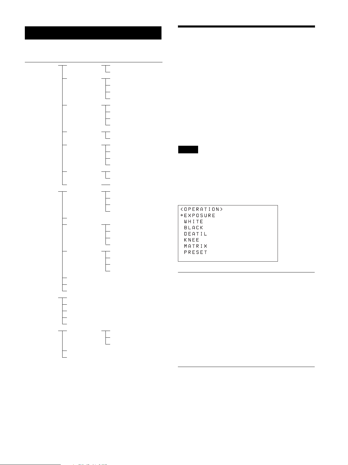
RM Menu List
OPERATION
Menu item Sub menu
item
OPERATION
page 43
CONFIG
page 46
AUTO I P SETU P
page 48
MAINTENANCE
page 49
EXPOSURE EX-COMP
WHITE WB MODE
BLACK ABB MODE
DETAIL SETTING
KNEE SETTING
MATRIX MATRIX
PRESET SPEED
RM SETUP AE CONFIG
SW ASSIGN
DIRECTION JOYSTICK PAN
GPI I/O SETTING
LAN
SERIAL
CONTROL I/F
SETUP IP
ASSIGN CAM
CLEAR TABLE
SWAP CAM
CAMERA TABLE
MODEL INFO MODEL
UPDATE MODE
RESET
Setup item See
page 43
AE LEVEL
R. WHITE
B. WHITE
OFFSET
R. BLACK
B. BLACK
M. BLACK
LEVEL
KNEE MODE
POINT
SLOPE
SELECT
CAM POWER
ZOOM
CAMERA FREQ
JOYSTICK TILT
ZOOM LEVER
FOCUS DIAL
TALLY MODE
COMMAND SEL
CAMERA LINK
S/NO
VERSION
page 43
page 44
page 44
page 44
page 44
page 44
page 44
page 44
page 44
page 44
page 44
page 44
page 44
page 44
page 44
page 44
page 44
page 44
page 46
page 46
page 46
page 46
page 46
page 46
page 47
page 47
page 47
page 47
page 47
page 47
page 47
page 48
page 48
page 48
page 48
page 48
page 48
page 48
page 48
page 49
page 49
page 49
page 49
page 49
You can check and change camera menu settings while
operating a camera. This menu is also used to set and
change the speed of movement betweens positions when
using the preset memory function.
During operation, the settings of the OPERATION
menu setup items display the settings configured on the
camera.
Accordingly, default settings are not indicated in the
description of each setting.
To store the settings changed using this menu, use the
preset memory function of the camera. For details about
items saved with a preset number, refer to the operating
instructions of each camera.
Notes
• Depending on the camera model, the settings
displayed on the unit and camera menu display may
not be the same. In this case, the settings displayed in
the camera menu are the actual settings.
• When changing a setting, there may be some delay
before the display is updated.
EXPOSURE
Sets the exposure compensation function of the target
camera.
EX-COMP
Turns the exposure compensation mode on/off.
AE LEVEL
Sets the control level for automatic camera brightness
control (exposure compensation level).
WHITE
Sets the white balance adjustment function of the target
camera.
43
Page 44

WB MODE
Settings Description
AUTO1 Automatically adjusts the white balance using
AUTO1.
AUTO2 Automatically adjusts the white balance using
AUTO2.
INDOOR Adjusts to a white balance suitable for indoor
shooting.
OUTDOOR Adjusts to a white balance suitable for outdoor
shooting.
ONE PUSH Executes a white balance adjustment. Shoot a
large white object in the center of the screen and
press the O.P.AWB button.
MANUAL Adjusts the white balance manually. Selecting this
enables the R. WHITE and B. WHITE items.
R. WHITE
Sets the R. WHITE value.
B. WHITE
Sets the B. WHITE value.
LEVEL
Adjusts the level of detail correction.
KNEE
Sets the KNEE correction function on the target camera.
SETTING
Turns the KNEE correction function on/off. When set to
ON, the high luminance parts of the image are
compressed.
KNEE MODE
Settings Description
AUTO Automatically calculates the optimum luminance
level at which knee correction is applied from the
luminance level of the image being shot.
MANUAL Allows you to adjust the luminance level at which
knee correction (POINT and SLOPE) is applied,
irrespective of the luminance level of the image
being shot.
OFFSET
Adjusts the offset level of the white convergence point.
Negative values shift the convergence point in the blue
direction, and positive values shift the convergence point
in the red direction.
BLACK
Sets the black balance adjustment function of the target
camera.
ABB MODE
Turns the black balance adjustment function on/off.
R. BLACK
Sets the R. BLACK value.
B. BLACK
Sets the B. BLACK value.
M. BLACK
Sets the M. BLACK value.
POINT
Adjusts KNEE POINT.
SLOPE
Adjusts the gradient of the slope above the knee point
(degree of compression).
MATRIX
Sets the MATRIX adjustment function on the target
camera.
MATRIX
Turns the MATRIX adjustment function on/off. When
set to ON, you can enhance or weaken a specific color
region while keeping the white convergence point
unchanged.
SELECT
Selects a built-in preset matrix used for matrix
calculation. You can choose from STD, HIGH SAT, and
FL LIGHT.
DETAIL
Sets the detail enhancement function of the target camera.
SETTING
Turns the detail correction function on/off. When set to
ON, you can set the level of detail correction.
PRESET
Sets the speed of movement when switching positions
using preset memory.
SPEED
Sets the speed of movement when switching positions
using preset memory.
44
Page 45

OPERATION menu support by camera model
Setup item Function Conditions BRC-
EXPOSURE EX-COMP Exposure compensation
function on/off
AE LEVEL Exposure compensation
level setting
WHITE WB MODE White balance adjustment
method selection
R. WHITE R. WHITE value setting Enabled when WB MODE is set
B. WHITE B. WHITE value setting Enabled when WB MODE is set
OFFSET Convergence point offset
adjustment
BLACK ABB MODE Black balance adjustment
function setting
R. BLACK R. BLACK value setting – – Yes –
B. BLACK B. BLACK value setting – – Yes –
M. BLACK M. BLACK value setting – Yes – –
DETAIL SETTING Detail correction function
on/off
LEVEL Detail correction level
setting
KNEE SETTING KNEE correction function
on/off
KNEE MODE KNEE adjustment function
AUTO/MA NUAL
selection
POINT KNEE POINT setting Enabled when KNEE MODE is
SLOPE KNEE slope setting Enabled when KNEE MODE is
MATRIX MATRIX MATRIX adjustment
function on/off
SELECT Built-in preset matrix
selection used for matrix
calculation
PRESET SPEED Speed of movement setting
when switching positions
using the preset memory
function.
–YesYes
Enabled when EX-COMP is set to
ON.
–YesYes
to MANUAL.
to MANUAL.
Enabled when WB MODE is set
to AUTO1 , AUTO2, o r ONE
PUSH.
––Yes–
–Yes
Enabled when SETTING is set to
ON.
–YesYes–
Enabled when SETTING is set to
ON.
set to MANUAL.
set to MANUAL.
–YesYes–
Enabled when MATRIX is set to
ON.
–YesYes–
Yes: Supported
–: Not supported
BRC-
X1000/
H900
H800
*1
Ye s Ye s Ye s
*2
Ye s Ye s Ye s
Ye s Ye s Ye s
Ye s Ye s –
*1
Ye s Ye s
Ye s Ye s Y es
Ye s Ye s –
Ye s Ye s –
Ye s Ye s –
Ye s Ye s –
SRG-
360SHE
Ye s
*3
Ye s
*1
*4
*1 Always set to ON. Cannot be set to OFF.
*2 AUTO2 cannot be selected.
*3 When AUTO2 is selected, the ATW white balance mode on the camera is applied.
*4 The APERTURE setting of the PICTURE menu on the camera is applied.
45
Page 46

CONFIG
This menu is used to configure functions of the unit.
ZOOM
Settings (Bold:
default value)
LEVER Controls the zoom of the target camera
JOYSTICK Controls the zoom of the target camera
Description
using the ZOOM lever on the lens
control block.
using the ZOOM ring on the joystick.
CAMERA FREQ
Note
During CONFIG menu operation, operation using
controls other than the buttons and knobs on the menu
control block is not supported.
RM SETUP
Sets the operation of the unit.
AE CONFIG
You can select the following exposure modes when the
AE button on the lens control block is off. To apply the
setting, after selection, turn the AE button on and then
off again.
Settings (Bold:
default value)
MANUAL The gain (GAIN), electronic shutter
SHUT Pri Automatically adjusts the exposure
IRIS Pri Automatically adjusts the exposure
GAIN Pri Automatically adjusts the exposure
Description
speed (SPEED), and iris (IRIS) can be
adjusted manually.
using the gain and iris. Adjust the
electronic shutter speed (SPEED)
manually.
using the gain and electronic shutter
speed. Adjust the iris (IRIS) manually.
using the electronic shutter speed
(SPEED) and iris (IRIS). Adjust the
gain (GAIN) manually.
Settings (Bold:
default value)
59.94 Selects the frame rate for the shutter
50
* The shutter speed is displayed in the status display (page 38)
for the ASSIGN 3 button.
Description
speed displayed in the menu. You can
select from 59.94 [Hz] and 50 [Hz].
*
SW ASSIGN
Assign functions to the ASSIGN 1 to ASSIGN 6 buttons
of the unit.
Note
In this version, the assignment of the ASSIGN buttons is
fixed and cannot be changed.
Assign
button
ASSIGN 1 BACK LIGHT Settings are fixed.
ASSIGN 2 FLICKER
ASSIGN 3 STATUS
ASSIGN 4 DETAIL
ASSIGN 5 KNEE
ASSIGN 6 AE LEVEL
Settings Description
DIRECTION
Sets the control direction of the joystick, ZOOM lever,
and FOCUS knob.
JOYSTICK PAN
CAM POWER
Settings (Bold:
default value)
EACH Only the target camera turns on/off
ALL All cameras registered in the camera
Description
when using the CAM POWER button.
table turn on/off when using the CAM
POWER button.
Settings (Bold:
default value)
STANDARD Inclining the joystick to the right pans
REVERSE Inclining the joystick to the right pans
46
Description
the camera to the right. Inclining to the
left pans the camera to the left.
the camera to the left. Inclining to the
left pans the camera to the right.
Page 47

JOYSTICK TILT
Settings (Bold:
default value)
STANDARD Inclining the joystick forward tilts the
REVERSE Inclining the joystick forward tilts the
Description
camera up. Inclining rearward tilts the
camera down.
camera down. Inclining rearward tilts
the camera up.
Settings (Bold:
default value)
NORMAL Displays the tally input lamp
ON AIR Displays the tally input lamp
Description
corresponding to the number of the
camera with tally input ON, and
automatically selects the camera as the
target camera.
corresponding to the number of the
camera with tally input ON.
ZOOM LEVER
Settings (Bold:
default value)
STANDARD Moving the ZOOM lever to the W side
REVERSE Moving the ZOOM lever to the W side
Description
(Wide) zooms out, and moving to the T
side (Tele) zooms in.
(Wide) zooms in, and moving to the T
side (Tele) zooms out.
FOCUS DIAL
Settings (Bold:
default value)
STANDARD Turning the FOCUS knob clockwise
REVERSE Turning the FOCUS knob clockwise
Description
moves the focus in the Far direction,
and turning counterclockwise moves
the focus in the Near direction.
moves the focus in the Near direction,
and turning counterclockwise moves
the focus in the Far direction.
GPI I/O
Sets the GPI I/O connector signal format and tally
operation mode.
SETTING
Settings (Bold:
default value)
INPUT Sets the control signal direction of the
OUTPUT Sets the control signal direction of the
Description
GPI I/O connector to INPUT. In this
case, connect a tally control input
signal to the connector.
GPI I/O connector to OUTPUT. In this
case, the connector functions as a
contact output connector which
outputs the camera number of the
target camera.
COMMAND SEL
Settings (Bold:
default value)
STANDARD Sets the input/output method to
EXPAND Handles camera numbers as binary
Description
STANDARD method. The camera
numbers and input/output pin numbers
have a 1:1 correspondence.
• If the unit and cameras are
connected by serial connection,
cameras 1 to 7 correspond to input/
outputs 1 to 7.
• If the unit and cameras are
connected by LAN connection,
cameras 1 to 10 in group 1
correspond to input/outputs 1 to 10.
numbers.
• Tally input numbers 8 and higher in
a serial connection are ignored. In
this case, the response is equivalent
to no input.
• Numbers in a LAN connection,
corresponding to cameras 1 to 10 in
groups 1 to 10, are handled as the
numbers 1 to 100. Tally input
numbers 101 and higher are
ignored. In this case, the response is
equivalent to no input.
CAMERA LINK
Settings (Bold:
default value)
ON, OFF Turns tally lamp control on/off. The
Tally lamp control operation
Description
tally lamp control operation varies
depending on the combination of the
SETTING and CAMERA LINK
settings. For details, see “Tally lamp
control operation” below.
TALLY M O DE
This setting is enabled when SETTING is set to INPUT.
47
Tall y l a m p
Tally input lamps
Page 48

CAMERA
LINK
setting
OFF Tally input
ON Tally input
Control
lamps
lamps 1 to 10
Camera tally
lamp
lamps 1 to 10
Camera tally
lamp
SETTING setting
IN OUT
Displays the
tally input
lamp
corresponding
to the number
of the camera
with tally input
ON.
The camera tally lamps are not
controlled. A tally lamp ON/
OFF command is not sent.
Displays the
tally input
lamp
corresponding
to the number
of the camera
with tally input
ON.
Displays the
camera tally
lamp
corresponding
to the number
of the camera
with tally input
ON.
Not lit
Not lit
The tally lamp
of the target
camera
becomes the
control target,
and the camera
tally lamp
lights up.
AUTO IP SETUP
This menu is used to configure the automatic assignment
of IP addresses of the detected cameras on the network.
This is used when the unit and cameras are connected by
LAN connection.
SETUP IP
Assigns IP addresses to cameras automatically, and then
assign the cameras to the camera selection buttons of the
unit.
For details, see “Assignment using AUTO IP SETUP
>SETUP IP” (page 17).
ASSIGN CAM
LAN
Configures the network of the unit when the unit and
target cameras are connected by LAN connection.
For details, see “Setting the IP address of the unit”
(page 14).
SERIAL
Configures serial connections when the unit and target
cameras are connected by serial connection.
For details, see “Configuring a serial connection”
(page 23).
CONTROL I/F
Displays the enabled control interface of cameras.
When LAN connection is enabled, LAN is displayed.
When serial connection is enabled, SERIAL is
displayed.
Assigns cameras that already have configured IP
addresses to the camera selection buttons of the unit.
For details, see “Assignment using AUTO IP SETUP
>ASSIGN CAM” (page 18).
CLEAR TABLE
Clears the camera information.
For details, see “To clear the camera table” (page 19).
SWAP CAM
Swaps the camera number and camera information of
two cameras registered in the camera table.
For details, see “To swap camera numbers” (page 19).
CAMERA TABLE
Displays the camera information (IP address and MAC
address) registered in the camera table.
For details, see “To check the camera table” (page 20).
48
Page 49

MAINTENANCE
This menu is used to perform maintenance of the unit.
MODEL INFO
Displays model information about the unit.
MODEL
Display Description
RM-IP500 Displays the model name of the unit.
S/NO
RESET
Resets all settings stored on the unit to their default
values.
For details, see “Restoring Factory Default Settings”
(page 39).
Display Description
1234567 Displays the serial number of the unit.
VERSION
Display Description
X.XX Displays the firmware version of the
unit.
UPDATE MODE
To permit access to the unit from a PC, set UPDATE
MODE to ON. Enable update mode when backing up or
restoring settings, or using the setup software RM-IP
Setup Tool.
When UPDATE MODE is set to ON, all operations are
disabled, except the VALUE knob and VALUE button
operation.
To return to normal operation mode, set UPDATE
MODE to OFF.
For details, see “Using a Setup PC” (page 25).
Note
When UPDATE MODE is set to ON, the buttons on the
control panel blink at roughly 1-second intervals.
Blinking indicates that external access to the unit is
permitted. It does not indicate a malfunction.
49
Page 50

Appendix
Troubleshooting
Before bringing in your unit for service, check the following as a guide to troubleshoot the problem. If the problem
cannot be corrected, consult with your Sony dealer.
Symptom Cause Remedy
The power of the unit is not
turned on.
The camera cannot be operated
with the unit.
Operation is not possible while
the control panel buttons and
LEDs are blinking.
The group number is not
displayed, and the GROUP LEFT
and GROUP RIGHT buttons
cannot be operated.
CAMERA 8 to 10 buttons cannot
be selected.
The AC power adapter is not connected to the
DC IN 12V jack firmly.
The AC power cord is not inserted firmly into
the AC power adapter or the AC outlet.
The physical connection and communication
method settings are different.
(Serial connection)
The communication baud rate setting of the
camera and the unit differ.
(Serial connection)
The VISCA RS-422 connection is not
correctly made.
(LAN connection)
The GROUP number differs.
(LAN connection)
There is a mismatch between the MAC
address and IP address information of the
connected camera and the registered camera
table.
A menu other than the FUNCTION menu,
OPERATION menu, RM menu, or top menu
is displayed.
The remote controller is set to update mode. Set MAINTENANCE >UPDATE MODE to OFF in
Not using a LAN connection. These functions are enabled for a LAN connection
Insert the power cord firmly as far as it will go.
Insert the power cord firmly as far as it will go.
Check the communication method (LAN or SERIAL)
in CONGIF >CONTROL I/F in the RM menu.
Change the communication method setting if it is
different to the physical connection method.
• “VISCA over IP (LAN) connection” (page 14)
• “Configuring a serial connection” (page 23)
Note
LAN connection and serial connection cannot be used
at the same time.
Set the baud rate to the same setting as the camera
(9,600 bps or 38,400 bps) (page 23).
Check the connection of the VISCA RS-422
connectors and the RS-422 cable (page 21 and 22).
Select the correct GROUP number of the target
camera (page 27).
Delete the camera table contents using AUTO IP
SETUP >CLEAR TABLE in the RM menu, and build
the camera table again (page 19).
Select the RM menu top menu.
the RM menu (page 25).
only.
50
Page 51

Specifications
Dimensions
Top
Input/output connectors
Control input/output
VISCA RS-422 connector: RJ-45
LAN connector: RJ-45, 10BASE-T/
100BASE-TX auto sensing
GPI I/O: D-sub 15-pin TALLY IN/
CONTACT OUT
Control signal format (RS-422 communication)
9,600 bps/38,400 bps
Power connector
JEITA type 4 (12 V DC)
General specifications
Input voltage 12 V DC (10.8 V to 13.2 V)
Current consumption
0.6 A max. (All lamps lit)
Operating temperature
0
°C to 40 °C (32 °F to 104 °F)
Storage temperature
–20
Dimensions 306 mm × 159.3 mm × 224.1 mm
°C to +60 °C (–4 °F to 140 °F)
1
(12
/8in × 6 3/8in × 8 7/8in)
(width / height / depth) (excluding
protrusions)
Mass Approx. 2.4 kg (5 lb 4.7 oz)
Optional accessories
AC adapter (AC-UES1230 series)
Front
)
/
3
58.9
(2
)
/
1.8
3
(
306 (12 1/8)
Unit: mm (in)
)
8
/
3
8
1
180 (7
32
/8)
63 (2 1/2)
Unit: mm (in)
159.3 (6
For details about the recommended AC adapter, contact
your Sony sales representative.
Design and specifications are subject to change without
notice.
Side
3
)
/
8
(
2
2
2
7
2
)
/
(
1
2
2
3
t)
h
g
i
r
t/
f
e
l
(
0
8
1
224.1 (8 7/8)
4
8
.
5
(
1
1
/
3
2
)
(
f
r
o
n
t
/
1
(
)
/
7
(
8
)
t
h
ig
r
/
t
f
e
l
b
a
ck
)
Unit: mm (in)
51
Page 52

Rear
Pin assignments
VISCA RS-422 output connector
18
63 (2 1/2)
180 (7
1
/8)
Pin Signal name
1 RXD OUT–
Unit: mm (in)
2 RXD OUT+
3 TXD OUT–
4GND
5GND
6 TXD OUT+
7 No connection
8 No connection
GPI I/O connector (D-sub 15-pin, female)
1
9
Pin Signal name
1 TALLY IN/CONTACT OUT 1
2 TALLY IN/CONTACT OUT 2
3 TALLY IN/CONTACT OUT 3
4 TALLY IN/CONTACT OUT 4
5 TALLY IN/CONTACT OUT 5
6 TALLY IN/CONTACT OUT 6
7 TALLY IN/CONTACT OUT 7
8 TALLY IN/CONTACT OUT 8
9 TALLY IN/CONTACT OUT 9
10 TALLY IN/CONTACT OUT 10
11 No connection
12 No connection
13 GND
14 GND
15 GND
8
15
52
Page 53

TALLY/CONTACT connector input
TALLY/CONTACT connector output
connection example
Switch or relay connection
External device RM-IP500
Open-collector connection
External device RM-IP500
+3.3 V
+3.3 V
10 kΩ
10 kΩ
47 kΩ
47 kΩ
47 kΩ
47 kΩ
connection example
External deviceRM-IP500
Recommended voltage: 5 V
(Maximum 24 V)
Maximum load
current: 100 mA
4.7 Ω
Load
Input waveform of TALLY/CONTACT
connector
Approx. 2.7 V
(open voltage)
0.2 V or less
(closed voltage)
90%
10%
Tlow
Tfall Trise
Tfall, Trise: within 5 msec
Tlow, Thigh: 33 msec or more
Thigh
53
In Expand mode, the following can also
be applied:
Tally in 1
Tally in 2
Tally in 7
Thold
Tskew Tskew
Tskew: within 0.5 msec
Thold: 33 msec or more
Page 54

License
This software partially supports component uIP.
Therefore the following license conditions apply.
Copyright (c) 2001-2006, Adam Dunkels and the
Swedish Institute of Computer Science All rights
reserved.
Redistribution and use in source and binary forms, with
or without modification, are permitted provided that the
following conditions are met:
1. Redistributions of source code must retain the above
copyright notice, this list of conditions and the
following disclaimer.
2. Redistributions in binary form must reproduce the
above copyright notice, this list of conditions and the
following disclaimer in the documentation and/or
other materials provided with the distribution.
3. The name of the author may not be used to endorse or
promote products derived from this software without
specific prior written permission.
THIS SOFTWARE IS PROVIDED BY THE AUTHOR
`AS IS' AND ANY EXPRESS OR IMPLIED
WARRANTIES, INCLUDING, BUT NOT LIMITED
TO, THE IMPLIED WARRANTIES OF
MERCHANTABILITY AND FITNESS FOR A
PARTICULAR PURPOSE ARE DISCLAIMED. IN
NO EVENT SHALL THE AUTHOR BE LIABLE FOR
ANY DIRECT, INDIRECT, INCIDENTAL, SPECIAL,
EXEMPLARY, OR CONSEQUENTIAL DAMAGES
(INCLUDING, BUT NOT LIMITED TO,
PROCUREMENT OF SUBSTITUTE GOODS OR
SERVICES; LOSS OF USE, DATA, OR PROFITS; OR
BUSINESS INTERRUPTION) HOWEVER CAUSED
AND ON ANY THEORY OF LIABILITY, WHETHER
IN CONTRACT, STRICT LIABILITY, OR TORT
(INCLUDING NEGLIGENCE OR OTHERWISE)
ARISING IN ANY WAY OUT OF THE USE OF THIS
SOFTWARE, EVEN IF ADVISED OF THE
POSSIBILITY OF SUCH DAMAGE.
54
Page 55

Sony Corporation
 Loading...