

Page 1

SOLID-STATE MEMORY CAMCORDER
PXW-X500
OPERATION MANUAL [English]
1st Edition (Revised 7)
Page 2

Table of Contents
Before Using This Unit ................................................................................ 9
Chapter 1 : Overview
Features ...................................................................................................... 10
Locations and Functions of Parts............................................................. 12
Power Supply .................................................................................. 12
Accessory Attachments................................................................... 12
Operation and Connectors Section.................................................. 14
Screen Display............................................................................................ 24
LCD Monitor Information Screen (Status Display)........................ 24
Viewfinder Screen........................................................................... 25
Chapter 2 : Preparations
Preparing a Power Supply ........................................................................ 32
Using a Battery Pack....................................................................... 32
Using AC Power ............................................................................. 33
Attaching the Viewfinder .......................................................................... 33
Attaching the Viewfinder................................................................ 33
Adjusting the Viewfinder Position.................................................. 34
Using the BKW-401 Viewfinder Rotation Bracket ........................ 34
Detaching the Eyepiece................................................................... 35
Adjusting the Viewfinder Focus and Screen................................... 36
Using the Camcorder for the First Time................................................. 37
Mounting and Adjusting the Lens............................................................ 38
Adjusting the Flange Focal Length................................................. 38
Preparing the Audio Input System .......................................................... 39
Connecting a Microphone to the MIC IN Connector...................... 39
Connecting Microphones to the AUDIO IN Connectors................ 40
Attaching a Portable Wireless Tuner (for use with wireless
microphone).............................................................................. 41
Connecting Line Input Audio Equipment....................................... 43
Tripod Mounting ....................................................................................... 44
Connecting a Video Light ......................................................................... 45
Using the Shoulder Strap .......................................................................... 45
2
Page 3

Adjusting the Shoulder Pad Position....................................................... 46
Chapter 3 : Adjustments and Settings
Setting the Video Format .......................................................................... 47
Selecting the File System................................................................ 51
Switching the System Frequency.................................................... 51
Switching the Video Format ........................................................... 51
Adjusting the Black Balance and White Balance ................................... 52
Adjusting the Black Balance........................................................... 52
Adjusting the White Balance .......................................................... 53
Setting the Electronic Shutter................................................................... 55
Shutter Modes ................................................................................. 55
Selecting the Shutter Mode and Shutter Speed............................... 55
Setting Auto Iris......................................................................................... 57
Adjusting the Audio Level ........................................................................ 59
Manually Adjusting the Audio Levels of the Audio Inputs
from the AUDIO IN CH-1/CH-2 Connectors........................... 59
Manually Adjusting the Audio Level of the MIC IN Connector.... 60
Recording Audio on Channels 3 and 4 ........................................... 60
Setting Time Data ...................................................................................... 61
Setting the Timecode....................................................................... 61
Setting the User Bits........................................................................ 62
Synchronizing the Timecode........................................................... 62
Checking Camcorder Settings and Status Information (Status
Screens)................................................................................................. 64
Chapter 4 : Shooting
Handling SxS Memory Cards................................................................... 67
Handling SD Cards for Saving Configuration Data............................... 71
About SxS Memory Cards .............................................................. 67
Loading and Ejecting SxS Memory Cards...................................... 68
Selecting the SxS Memory Card to Use.......................................... 69
Formatting (Initializing) SxS Memory Cards................................. 69
Checking the Remaining Recording Time...................................... 70
Restoring SxS Memory Cards......................................................... 70
Formatting (Initializing) SD Cards ................................................. 71
Inserting/Ejecting SD Cards for Saving Configuration Data.......... 72
Checking the Remaining Capacity.................................................. 72
3
Page 4

Using a Media Adaptor ............................................................................. 72
XQD Memory Cards....................................................................... 72
SD Cards ......................................................................................... 73
Basic Operations........................................................................................ 74
Playing Recorded Clips................................................................... 75
Advanced Operations ................................................................................ 76
Recording Shot Marks..................................................................... 76
Setting Clip Flags............................................................................ 76
Recording Retroactive Images (Picture Cache Rec Function)........ 77
Recording Time-lapse Video (Interval Rec Function).................... 78
Shooting with Slow & Quick Motion ............................................. 79
Recording with the Clip Continuous Rec Function ........................ 81
Recording Video Simultaneously to Two SxS Memory Cards
(Simul Rec)............................................................................... 82
Recording Proxy Data ............................................................................... 83
Proxy Recording using the Camcorder........................................... 83
SD Cards ......................................................................................... 83
Formatting (Initializing) SD Cards ................................................. 83
Checking the Remaining Capacity.................................................. 84
Recording Proxy Data..................................................................... 84
Changing Proxy Recording Settings............................................... 85
Checking Proxy Recording Settings ............................................... 85
Planning Metadata Operations ................................................................ 85
Loading a Planning Metadata File into Camcorder’s Internal
Memory when Recording a Clip............................................... 85
Defining Clip Names in Planning Metadata ................................... 86
Defining Shot Mark Names in Planning Metadata ......................... 87
Operating via the REMOTE Connector.................................................. 88
Adjusting the Camcorder from the Remote Control Unit............... 88
Operating the Menu from the RM-B170......................................... 90
Major Functions Supported on the RCP-1001/1501, RM-B170..... 91
Obtaining Location Information (GPS)................................................... 94
Connecting Devices using Wireless LAN................................................. 95
Attaching the IFU-WLM3............................................................... 96
Attaching the CBK-WA02.............................................................. 96
Connecting using Wireless LAN Access Point Mode (Wi-Fi
Access Point Mode).................................................................. 98
Connecting using Wireless LAN Station Mode (Wi-Fi Station
Mode)........................................................................................ 99
Connecting to the Internet ...................................................................... 100
Preparations for Connecting Using a Modem or LAN Cable....... 100
Connecting Using a Modem.......................................................... 102
Connecting Using a LAN Cable ................................................... 102
4
Page 5

Connecting Using Wireless LAN Station Mode (Wi-Fi Station
mode) ...................................................................................... 104
Connecting Using a Device........................................................... 104
Connecting to an Access Point using the Setup Menu.................. 104
Network Functions and Network Connection Settings Support ... 106
Transferring Files.................................................................................... 107
Preparation .................................................................................... 107
Selecting and Transferring Files ................................................... 107
Transmitting Streaming Video and Audio............................................ 109
Preparation .................................................................................... 109
Starting Streaming......................................................................... 109
Stopping Streaming....................................................................... 110
High-Quality Streaming Using Network Client Mode......................... 110
Setting Network Client Mode ....................................................... 110
Wi-Fi Remote Control............................................................................. 112
Displaying the Wi-Fi Remote Control.......................................... 112
Wi-Fi Remote Screen.................................................................... 113
Web Menu ................................................................................................ 115
Streaming Format Settings............................................................ 115
Monitoring Settings....................................................................... 116
Streaming Settings ........................................................................ 116
Proxy Format Settings................................................................... 117
Wireless LAN Station Settings ..................................................... 117
Wired LAN Settings...................................................................... 118
Transfer (Upload) Settings............................................................ 119
Monitoring File Transfers (Job List)............................................. 121
Chapter 5 : Clip Operations
Clip Operations on the Thumbnail Screen............................................ 122
Thumbnail Screen ......................................................................... 122
Playing Clips................................................................................. 123
Basic Thumbnail Menu Operations .............................................. 124
Protecting Clips............................................................................. 125
Copying Clips ............................................................................... 125
Deleting Clips................................................................................ 126
Displaying Clip Properties............................................................ 127
Adding/Deleting Clip Flags on Clips............................................ 127
Filtering Clips Displayed using the Filtered Clip Screen.............. 128
Adding/Deleting Essence Marks in Clips..................................... 128
Filtering Clips (Frames) using the Essence Mark Thumbnail
Screen...................................................................................... 129
Changing the Index Picture of a Clip............................................ 129
5
Page 6

Thumbnail Menu........................................................................... 130
Chapter 6 : Menu Display and Settings
Setup Menu Organization....................................................................... 131
User Menu..................................................................................... 131
Operation Menu ............................................................................ 131
Paint Menu .................................................................................... 131
Thumbnail menu ........................................................................... 132
Maintenance Menu........................................................................ 132
File Menu ...................................................................................... 132
Basic Setup Menu Operations ................................................................ 133
Editing the User Menu ............................................................................ 137
Displaying the Edit User Menu Screen......................................... 137
Adding Items and Sub-Items......................................................... 137
Editing Sub-Items.......................................................................... 137
Deleting Items............................................................................... 138
Moving Items ................................................................................ 138
Restoring the User Menu to Factory Default State ....................... 139
Menu List.................................................................................................. 140
User Menu (Factory Default Configuration)................................. 140
Operation Menu ............................................................................ 141
Paint Menu .................................................................................... 156
Maintenance Menu........................................................................ 164
File Menu ...................................................................................... 178
Assigning Functions to Assignable Switches ......................................... 182
Functions That Can Be Assigned to the ASSIGN. 0 Switch ........ 182
Functions That Can Be Assigned to the ASSIGN. 2 Switch ........ 183
Functions That Can Be Assigned to the ASSIGN. 1 and 3
Switches, the ASSIGNABLE 4 and 5 Switches, and the COLOR
TEMP. Button......................................................................... 183
Functions That Can Be Assigned to the RET Button on the
Lens......................................................................................... 185
Chapter 7 : Saving and Loading User Setting Data
Saving and Loading Settings................................................................... 187
Saving and Loading User Files............................................................... 188
Saving User Files .......................................................................... 188
Loading User Files........................................................................ 188
Saving and Loading User Menu Item Files ........................................... 189
Saving User Menu Item Files........................................................ 189
6
Page 7

Loading User Menu Item Files ..................................................... 189
Saving and Loading ALL Files............................................................... 190
Saving Settings Data as an ALL file............................................. 190
Loading Settings Data................................................................... 190
Restoring All Current Settings to Preset Values........................... 190
Saving All Current Settings as Preset Values ............................... 190
Resetting Current Settings and Preset Values to Factory Default
Settings.................................................................................... 191
Saving and Loading Scene Files ............................................................. 191
Saving Scene Files ........................................................................ 191
Loading Scene Files...................................................................... 192
Saving and Loading Reference Files...................................................... 193
Saving Reference Files.................................................................. 193
Loading a Reference File from an SD Card.................................. 193
Resetting Current Settings and Preset Values to Factory Default
Settings.................................................................................... 193
Saving and Loading Lens Files............................................................... 194
Setting Lens File Data................................................................... 194
Saving Lens Files.......................................................................... 194
Loading Lens Files........................................................................ 194
Loading Lens Files Automatically................................................ 195
Saving and Loading Gamma Files ......................................................... 195
Checking the Current Gamma File Settings (File Names)............ 195
Loading User Gamma Files from an SD Card.............................. 195
Resetting User Gamma Files to Initial State................................. 195
Chapter 8 : Connecting External Devices
Connecting External Monitors ............................................................... 197
Managing/Editing Clips with a Computer............................................ 198
Using the ExpressCard Slot of a Computer .................................. 198
USB Connection with a Computer................................................ 199
Connecting Portable Storage/USB Media..................................... 200
Configuring a Shooting and Recording System.................................... 203
Tally and Call Indicators............................................................... 203
Recording External Input Signals and Return Display ....................... 206
Chapter 9 : Maintenance
Testing the Camcorder............................................................................ 209
7
Page 8

Appendix
Maintenance............................................................................................. 209
Cleaning the Viewfinder ............................................................... 209
Note about the Battery Terminals ................................................. 210
Error/Warning System............................................................................ 211
Error Display................................................................................. 211
Warning Display ........................................................................... 211
Caution and Operation Confirmation Display .............................. 213
Messages Displayed During Operation.................................................. 214
Items Saved in User Data........................................................................ 222
User Menu..................................................................................... 222
Operation Menu ............................................................................ 222
Paint Menu .................................................................................... 226
Thumbnail Menu........................................................................... 229
Maintenance Menu........................................................................ 230
File Menu ...................................................................................... 235
Special Recording Support by Recording Format ............................... 237
Picture Cache Rec Mode Settings .......................................................... 238
Usage Precautions.................................................................................... 239
Exchanging the Battery of the Internal Clock...................................... 242
Specifications............................................................................................ 242
General .......................................................................................... 242
Input/Output Section ..................................................................... 245
Camera Section ............................................................................. 245
Audio Section................................................................................ 246
Display Section ............................................................................. 246
Media Section................................................................................ 246
Accessories.................................................................................... 246
Related Equipment........................................................................ 246
Chart of Peripheral Devices and Accessories........................................ 249
MPEG-4 Visual Patent Portfolio License .............................................. 250
END USER LICENSE AGREEMENT ................................................. 250
Open Software Licenses .......................................................................... 255
Trademarks.............................................................................................. 256
8
Page 9

Before Using This Unit
After purchasing the Sony PXW-X500 SolidState Memory Camcorder, it is necessary to set
the date and time of the internal clock and to set
the user language.
For details about how to make settings, see “Using
the Camcorder for the First Time” (page 37).
Note
Before attaching/removing optional components or
accessories to/from the PXW-X500 (referred to as the
“camcorder”), be sure to turn the power of the camcorder
off.
9
Page 10

Chapter1 Overview
Features
2
/3-inch type Power HAD FX CCD
Employs a 2/3-inch type IT (Interline Transfer)
progressive scan image sensor, with 2.20
megapixels for Full HD (1920×1080) resolution,
and a newly developed signal processor LSI that
achieves a high sensitivity of F11 (1080/59.94i)
or F12 (1080/50i) for shooting high quality video.
Multi-format support
In addition to conventional MPEG HD,
MPEG IMX, and DVCAM, the camcorder also
supports recording in high-definition XAVC HD
format, MPEG-4 SStP format employed in the
HDCAM SR, Apple ProRes format,
Avid DNxHD® format, allowing the camcorder
to be used in a wide range of applications for
recording material (see page 47).
* Installation of the PXWK-501 Codec Option and
PXWK-502 Codec Option Key, available separately,
is required for Apple ProRes and Avid DNxHD®
formats.
Slow & Quick Motion function
Supports slow and quick motion shooting as a
special recording function. This function allows
you to obtain special video effects when shooting
slow-moving or fast-moving subjects. You can
shoot full HD 1920×1080 resolution video at
frame rates of up to 1080/120P (see page 79).
Digital extender function
Equipped with a maximum 4× digital extender
function. Extends the zoom range electrically to
prevent the drop in sensitivity (F-drop) that
occurs in a conventional lens extender lens. It can
also be used together with a lens extender.
Picture Cache Rec function
The camcorder always maintains a cache of video
and audio data for a set interval (maximum of 15
seconds) in internal storage memory when
shooting, allowing you to record several seconds
of footage before actually starting to record.
Time-lapse recording (Interval Rec)
function
Using this function to shoot slow-moving
subjects allows you to capture the movement of
the subject for a shorter playback time. You can
use this function, for example, to record the
construction of a building or to observe the
growth of a plant.
Simultaneous recording function
You can record the same video simultaneously
onto two SxS memory cards using the
simultaneous recording function. This is useful
for making a video backup while shooting (see
page 82).
Network function
The wireless LAN connection function and the
supplied IFU-WLM3 USB Wireless LAN
Module enable you to configure and operate the
camcorder from a smartphone or tablet (see
page 95).
Wired LAN connection is also supported using a
CBK-WA02 Wireless LAN Adaptor (option,
5 GHz) and a CBK-NA1 Network Adaptor
(option).
Camcorder shooting/recording system
configuration
A shooting/recording system can be configured
using the pre-installed 50-pin interface, mounting
a CA-FB70/TX70 HD Camera Adaptor on the
camcorder, and connecting to a CCU (see
page 203).
10
Page 11

GPS function
The camcorder can record location information
and time information for recorded video using a
built-in GPS module, enabling you to trace
shooting locations in post-production (see
page 94).
External input signal recording and
return display function
An external input recording function is included
as standard for recording SDI input signals (see
page 206).
You can also display an external input as a return
signal on the viewfinder screen and LCD monitor
(see page 206).
Other functions
• The ALAC (automatic lens aberration
correction) function greatly reduces specific
patterns of chromatic aberration caused by the
lens (see page 169).
• The contrast of the video can be appropriately
adjusted using the gamma correction function,
which utilizes the dynamic range of the Power
HAD CCD sensor (see page 158). You can also
create customized gamma curves using user
gammas (see page 195).
• The focus assist function provides for easier
focusing in the viewfinder (see page 27).
Korea http://bp.sony.co.kr
China http://pro.sony.com.cn
India http://pro.sony.co.in
Sony Creative Software, software download
page:
http://www.sonycreativesoftware.com/
download/software_for_sony_equipment
Software Downloads
When the unit is used with a PC connection,
download any device drivers, plug-ins, and
application software you require from the
following websites.
Sony Professional products website:
U.S.A. http://pro.sony.com
Canada http://www.sonybiz.ca
Latin America http://sonypro-latin.com
Europe http://www.pro.sony.eu/pro
Middle East, Africa http://sony-psmea.com
Russia http://sony.ru/pro/
Brazil http://sonypro.com.br
Australia http://pro.sony.com.au
New Zealand http://pro.sony.co.nz
Japan http://www.sonybsc.com
Asia Pacific http://pro.sony-asia.com
11
Page 12

Locations and Functions of Parts
Power Supply
a LIGHT (video light) switch
Determines how a video light connected to the
LIGHT connector (see page 13) is turned on and
off.
AUTO : When the POWER switch of the video
light is in the on position, the video light is
turned on automatically while the camcorder
is recording.
MANUAL: You can turn the video light on or off
manually, using its own switch.
Note
When the camcorder is set for recording in Picture Cache
Rec mode, it is not possible to turn on the light before
operation to start recording is carried out (or while data
is being stored in memory).
output terminal of the BC-L70, BC-L70A,
BC-L160, BC-L500, or another battery charger.
d DC OUT 12V (DC power output)
connector (4-pin, female)
Supplies power for an optional WRR-855S/860C/
861/862 UHF Synthesized Diversity Tuner or
HDVF-750/L770 Viewfinder (maximum 1.8 A).
e Battery attachment shoe
Attach a BP-FLX75 Battery Pack. Alternatively,
you can attach an AC-DN2B/DN10 AC Adaptor
to operate the camcorder from an AC power
supply.
For details, see “Preparing a Power Supply”
(page 32).
For details, see “Attaching a Portable Wireless
Tuner (for use with wireless microphone)”
(page 41).
Note
For your safety, and to ensure proper operation of the
camcorder, Sony recommends the use of the BP-FLX75
Battery Pack.
f Camera adaptor connector
Enables connection of a CA-TX70/FB70 HD
Camera Adaptor. To connect an adaptor, remove
the cover.
Accessory Attachments
b POWER switch
Turns the main power supply on (?) and off (1).
c DC IN (DC power input) connector
(XLR type, 4-pin, male)
To operate the camcorder from an AC power
supply, connect an optional DC power cord to this
terminal and then connect the cord to the DC
a Shoulder strap fitting
Attach the supplied shoulder strap (see page 45).
12
Page 13

b Accessory shoe
Attach an optional accessory, such as a video
light (see page 45).
c Viewfinder front-to-back positioning
lever
Adjust the viewfinder position in the front-toback direction (see page 34).
d Viewfinder left-to-right positioning ring
Loosen this ring to adjust the left-to-right position
of the viewfinder (see page 34).
e Viewfinder attachment shoe
Attach the viewfinder (see page 33).
f VF (viewfinder) connectors (26-pin,
rectangular and 20-pin, round)
The analog interface connector (20-pin) is for
connection of an HDVF series viewfinder, and
the digital interface connector (26-pin) is for
connection of a CBK-VF02 HD viewfinder.
Use a connection cable to connect your
viewfinder to the corresponding connector.
Notes
• Do not connect viewfinders to both connectors at the
same time.
• When connecting or disconnecting an interface cable
to this connector, power off the camcorder first.
g Lens mount securing rubber
After locking the lens in position using the lens
locking lever, fit this rubber over the lower of the
two projections. This fixes the lens mount,
preventing it from coming loose.
h Viewfinder front-to-back positioning
knob (LOCK knob)
Loosen this knob to adjust the front-to-back
position of the viewfinder (see page 34).
i Attachment for optional microphone
holder
Attach an optional CAC-12 Microphone Holder
(see page 40).
k LIGHT (video light) connector (2-pin,
female)
A video light with a maximum power
consumption of 50 W, such as the Anton Bauer
Ultralight 2 or equivalent, can be connected (see
page 45).
l Lens cable clamp
Clamp the lens cable.
m MIC IN (microphone input) (+48 V)
connector (XLR type, 5-pin, female)
Connect a stereo microphone to this connector.
The power (+48 V) is supplied via this connector.
n LENS connector (12-pin)
Connect the lens cable to this connector.
Note
When connecting or disconnecting the lens cable to this
connector, power off the camcorder first.
o Tripod mount
When using the camcorder on a tripod, attach the
tripod adaptor (optional).
p Lens mount (special bayonet mount)
Attach the lens.
Consult a Sony service representative for
information about available lenses.
q Lens locking lever
After inserting the lens in the lens mount, rotate
the lens mount ring with this lever to lock the lens
in position.
After locking the lens, be sure to use the lens
mount securing rubber to prevent the lens from
becoming detached.
r Lens mount cap
Remove by pushing the lens locking lever up.
When no lens is mounted, keep this cap fitted for
protection from dust.
j Shoulder pad
Raise the shoulder pad fixing lever to adjust the
position in the front-to-rear direction. Adjust the
position for maximum convenience when
operating the camcorder on your shoulder (see
page 46).
13
Page 14
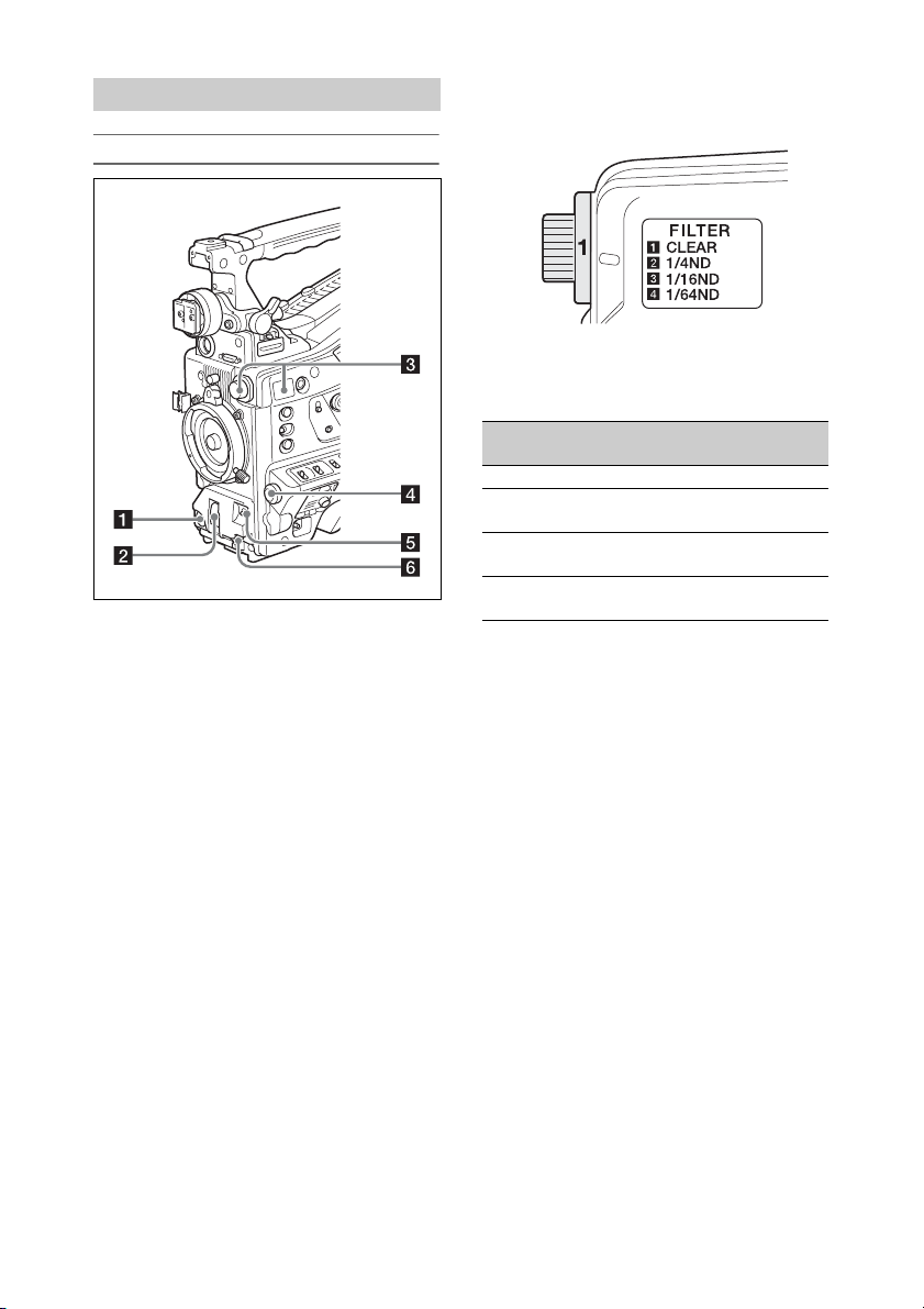
Operation and Connectors Section
Front
a REC START (recording start) button
Press to start recording. Press it again to stop
recording. The operation is the same as that of the
REC button on the lens.
b SHUTTER switch
Set to ON to use the electronic shutter. Push to
SELECT to switch the shutter speed or shutter
mode setting. When this switch is operated, the
new setting appears on the viewfinder screen for
about three seconds.
For details, see “Setting the Electronic Shutter”
(page 55).
c FILTER knob
Switches between four ND filters built into this
camcorder.
When this selector is used, the new setting
appears on the viewfinder screen for about three
seconds.
FILTER
knob setting
1 CLEAR
2 1/4 ND (attenuates light to
3 1/16 ND (attenuates light to
4 1/64 ND (attenuates light to
ND filter
approximately
approximately
approximately
1
/4)
1
/16)
1
/64)
You can change a Maintenance menu setting so
that different white balance settings can be stored
for different FILTER knob positions. This allows
you to automatically obtain optimum white
balance for the current shooting conditions in
linkage with the filter selection.
For details, see “Adjusting the White Balance”
(page 53).
d MENU knob
Changes the item selection or a setting within the
menu (see page 133).
e AUTO W/B BAL (automatic white/
black balance adjustment) switch
Activates the automatic white/black balance
adjustment functions.
WHITE: Adjust the white balance automatically.
If the WHITE BAL switch (see page 16) is
set to A or B, the white balance setting is
stored in the corresponding memory. If the
WHITE BAL switch is set to PRST, the
automatic white balance adjustment function
does not operate.
BLACK: Adjust the black set and black balance
automatically.
14
Page 15
You can use the AUTO W/B BAL switch even
when the ATW (Auto Tracing White Balance)
function is operating.
If you push the switch to the WHITE side once
more during the automatic white balance
adjustment, the adjustment is canceled and the
white balance setting returns to the original
setting.
If you push the switch to the BLACK side once
more during the automatic black balance
adjustment, the adjustment is canceled and the
black balance setting returns to the original
setting.
f MIC (microphone) LEVEL knob
Adjusts the input level of audio channels 1, 2, 3,
and 4 (see page 59).
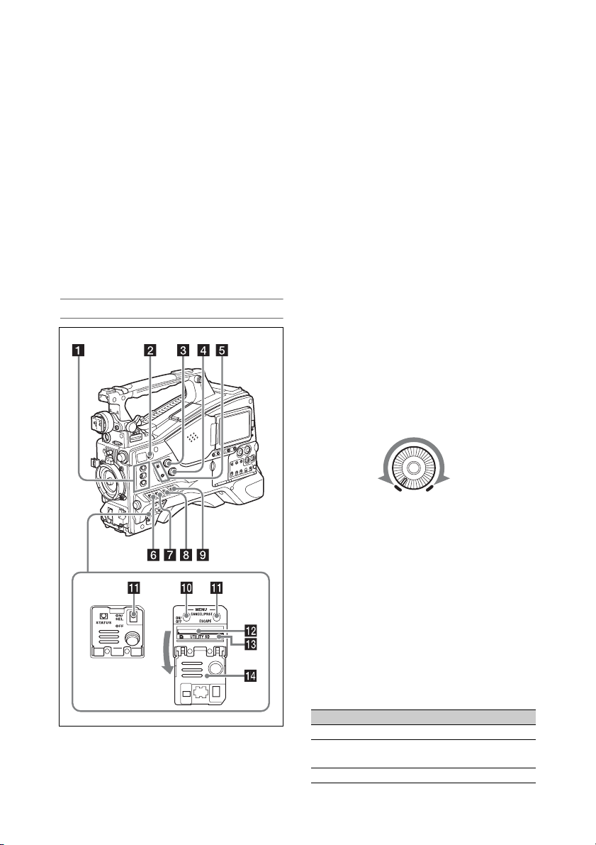
Right side (near the front)
a ASSIGN. (assignable) 1/2/3 switches
You can assign the desired functions to these
switches using Operation >Assignable Switch in
the setup menu (see page 182).
Off is assigned to the ASSIGN. 1/2/3 switches as
the factory default setting.
The ASSIGN. 1/3 switches are provided with an
indicator to show whether a function is assigned
to the switch (ON) or not (OFF).
b COLOR TEMP. (color temperature)
button
You can use this button to change the color
temperature when shooting (factory default). It
can be used as an assignable switch (see
page 183).
c ALARM (alarm tone volume
adjustment) knob
Controls the volume of the warning tone that is
output via the built-in speaker or optional
earphones. When the knob is turned to the
minimum position, no sound can be heard.
However, if Maintenance >Audio >Min Alarm
Volume in the setup menu is set to [Set], the
alarm tone is audible even when this volume
control is at the minimum position.
ALARM
Minimum
Maximum
d MONITOR (monitor volume
adjustment) knob
Controls the volume of the sound other than the
warning tone that is output via the built-in speaker
or earphones. When the knob is turned to the
minimum position, no sound can be heard.
e MONITOR (audio monitor selection)
switches
By means of combinations of the two switches,
you can select audio that you want to hear through
the built-in speaker or earphones.
Lower switch: CH-1/2
Upper switch Audio output
CH-1/CH-3 Channel 1 audio
MIX Channels 1 and 2 mixed audio
CH-2/CH-4 Channel 2 audio
(stereo)
a)
15
Page 16

Lower switch: CH-3/4
Upper switch Audio output
CH-1/CH-3 Channel 3 audio
MIX Channels 3 and 4 mixed audio
CH-2/CH-4 Channel 4 audio
a) By connecting stereo headphones to the EARPHONE
jack, you can hear the audio in stereo. (Maintenance
>Audio >Headphone Out in the setup menu must be
set to Stereo.)
(stereo)
a)
f ASSIGN. (assignable) 0 switch
You can assign a function using Operation
>Assignable Switch in the setup menu (see
page 182).
Off is assigned to these switches when the
camcorder is shipped from the factory.
This is a momentary type switch. Each press of
the switch turns the function assigned to this
switch on or off.
g GAIN switch
Switches the gain of the video amplifier to match
the lighting conditions during shooting. The gain
values corresponding to the L, M, and H settings
can be selected using Operation >Gain Switch in
the setup menu (see page 148) (factory settings
are L=0dB, M=6dB, and H=12dB).
When this switch is adjusted, the new setting
appears on the viewfinder screen for about three
seconds.
h OUTPUT/DCC (output signal/dynamic
contrast control) switch
Switches the video signal output from the camera
module, between the following two.
BARS: Output the color bar signal.
CAM: Output the video signal being shot. When
this is selected, you can switch DCC
1)
on and
off.
1) DCC (Dynamic Contrast Control):
Against a very bright background with the iris
opening adjusted to the subject, objects in the
background will be lost in the glare. The DCC
function will suppress the high intensity and restore
much of the lost detail. It is particularly effective for
shooting in the following cases.
• Shooting people in the shade on a sunny day
• Shooting a subject indoors, against a background
through a window
• Any high contrast scene
i WHITE BAL (white balance memory)
switch
Controls adjustment of the white balance.
PRST: Adjust the color temperature to the preset
value (the factory default setting: 3200K).
Use this setting when you have no time to
adjust the white balance.
A or B: Recall the white balance adjustment
settings already stored in A or B. Push the
AUTO W/B BAL switch (see page 14) to the
WHITE position to automatically adjust the
white balance and save the adjustment
settings in memory A or memory B.
1)
B (ATW
):When this switch is set to B and
Operation >White Setting >White
Switch<B> is set to [ATW] in the setup
menu, ATW is activated.
You can use the AUTO W/B BAL switch
even when ATW is in use.
When this switch is adjusted, the new setting
appears on the viewfinder screen for about three
seconds.
1) ATW (Auto Tracing White balance): The white
balance of the picture being shot is adjusted
automatically for varying lighting conditions.
Note
It may not be possible to adjust to the appropriate colors
using ATW, depending on the lighting and subject
conditions.
Examples:
• When a single color dominates the subject, such as sky,
sea, ground, or flowers.
• When the subject is under a light source of extremely
high or extremely low color temperature.
If execution of automatic tracing by the ATW function
takes an unacceptably long time or only results in an
inadequate effect, then execute the AWB function.
j MENU ON/OFF switch
To use the switch, open the cover.
This switch is used to display the menu on the
viewfinder screen or the test signal screen. Each
time the switch is pushed down, the menu screen
is turned on and off. The function of this switch is
the same as that of the MENU button in the
thumbnail screen operations section.
Note
It is not possible to turn off the menu screen by closing
the cover.
16
Page 17
k MENU CANCEL/PRST (preset) /
ESCAPE switch
To use the switch, open the cover.
This switch has different functions depending on
whether or not a menu is displayed.
Use the switch in the following way when the
menu is displayed.
CANCEL/PRST: Pushing this switch up to this
position after a setting is changed in the setup
menu displays the message to confirm
whether the previous settings are canceled.
Pushing this switch up to this position again
cancels the previous settings.
Pushing this switch up to this position before
a setting is changed in the setup menu or after
a setting change is canceled in the setup
menu displays the message to confirm
whether the setting is reset to the initial
value. Pushing this switch up to this position
again resets the settings to the initial value.
ESCAPE: Use this switch when the menu page,
which has a hierarchical structure, is opened.
Each time the switch is pushed to this
position, the page returns to one stage higher
in the hierarchy.
Use the switch in the following way when the
menu is not displayed.
CANCEL/PRST: Each time this switch is
pushed upward, a window to confirm the
menu settings and status of the camcorder
appears on the viewfinder screen (see
page 64). The window consists of eight
pages, which are switched each time the
switch is pushed upward.
ESCAPE: To clear the page, push this switch
down to the OFF position.
l UTILITY SD card slot
Insert an SD card for saving camcorder settings.
m ACCESS indicator
Lights up orange when the SD card is being
accessed.
Right side (near the rear)
a Built-in speaker
The speaker can be used to monitor E-E1) sound
during recording, and playback sound during
playback. The speaker also sounds alarms to
reinforce visual warnings (see page 211).
If you connect earphones to the EARPHONE
jack, the speaker output is suppressed
automatically.
1) E-E: Abbreviation of “Electric-to-Electric”. In E-E
mode, video and audio signals input to the camcorder
are output after passing through internal electric
circuits only. This can be used to check input signals.
n Switch cover
Open this cover to use the MENU ON/OFF
switch or the MENU CANCEL/PRST/ESCAPE
switch.
b LCD monitor
Displays remaining battery capacity, remaining
media capacity, audio levels, time data, and so on.
It also allows you to check camera and playback
pictures (see page 24).
17
Page 18

You can adjust the position and angle of the LCD
monitor.
c WARNING indicator
Lights up or flashes when an abnormality occurs
(see page 211).
d ACCESS indicator
Lights up in blue when data is written to or read
from the recording media.
e Protective cover of the audio control
section
Open to access the audio control section (see
page 19).
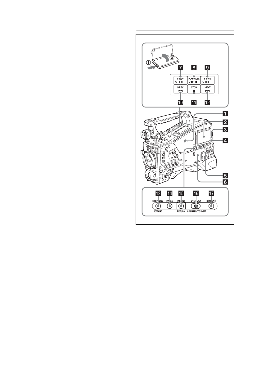
i F FWD (fast forward) button and
indicator
This plays back at high speed in the forward
direction. The playback speed changes in the
order ×4 t ×15 t ×24 with each press of the
button. The indicator lights during high-speed
playback in the forward direction.
j PREV (previous) button
This jumps to the first frame of the current clip.
If you press this together with the F REV button,
the jump is to the first frame of the first recorded
clip on the recording media.
If you press this button twice in rapid succession,
the jump is to the first frame of the preceding clip
(or the first frame of the current clip when no
preceding clips exist).
k STOP button
Press this button to stop playback.
l NEXT button
This jumps to the first frame of the next clip.
If you press this together with the F FWD button,
the jump is to the last frame of the last recorded
clip on the recording media.
f Protective cover of the thumbnail
screen operation section
Open to access the thumbnail screen operation
section (see page 19).
g F REV (fast reverse) button and
indicator
This plays back at high speed in the reverse
direction. The playback speed changes in the
order ×4 t ×15 t ×24 with each press of the
button. The indicator lights during high-speed
playback in the reverse direction.
h PLAY/PAUSE button and indicator
Press this button to view playback video images
using the viewfinder screen or the LCD monitor.
The indicator lights during playback.
Press this button again during playback to pause,
outputting a still image. At this time the indicator
flashes at a rate of once per second.
Pressing the F REV or F FWD button during
playback or pause starts high speed playback in
the forward or reverse direction.
m DISP SEL (display selection)/EXPAND
(expand function) button
With each press of this button, the display in the
LCD monitor changes as follows.
Display indication Description
Video with
superimposed
information (CHAR)
Video without
superimposed
information (MONI)
Status display
(STATUS)
(see page 24)
The LCD monitor displays
the same text information as
the viewfinder.
Only the video appears.
Counter indications,
warnings, audio levels, and
similar information appear.
No video image appears.
The EXPAND button function will be supported
in a future upgrade.
n HOLD (display hold) button
Pressing this button instan tly freezes the time d ata
displayed in the LCD monitor. (The timecode
generator continues running .) Pressing this button
again releases the hold.
For details of the time data display, see page 24.
18
Page 19

o RESET/RETURN button
Resets the value shown in the time data display in
the LCD monitor. According to the settings of the
PRESET/REGEN/CLOCK switch (see page 20)
and the F-RUN/SET/R-RUN switch (see
page 19), this button resets the display as follows.
Switch settings RESET/RETURN
DISPLAY switch:
COUNTER
DISPLAY switch: TC
PRESET/REGEN/
CLOCK switch:
PRESET
F-RUN/SET/R-RUN
switch: SET
DISPLAY switch:
U-BIT
PRESET/REGEN/
CLOCK switch:
PRESET
F-RUN/SET/R-RUN
switch: SET
a) Of the timecode bits for every frame recorded on the
media, those bits which can be used to record useful
information for the user such as scene number,
shooting place, etc.
For details, see “Setting Time Data” (page 61).
button operation
Reset counter to
00:00:00:00.
Reset timecode to
00:00:00:00.
Reset user bits data
00:00:00:00.
a)
to
This button returns to the previous screen when
pressed during thumbnail screen display or
essence mark thumbnail screen display.
p DISPLAY switch
This cycles the data displayed in the time data
display in the LCD monitor through the sequence
COUNTER, TC, and U-BIT (see page 24).
COUNTER: Display recording/playback
duration counter.
TC: Display timecode.
U-BIT: Display user bits data.
q BRIGHT (brightness) button
Switches the brightness of the LCD monitor
backlight.
Each press of the button selects the next setting in
the order shown in the following table. If you
press the button with the LCD monitor off, the
LCD backlight comes on in the H state.
Setting LCD monitor backlight
H High (select this to view the LCD
monitor outdoors in the daytime)
M Brightness between H and L
L Low (select this to view the LCD
monitor indoors or outdoors at night)
OFF Off (the display is also off)
Thumbnail screen operations section and audio
control section
a Thumbnail indicator
This lights when the thumbnail screen is
displayed.
b THUMBNAIL button
Press this button to display the thumbnail screen
(see page 122) and to carry out a thumbnail
operation.
Press once more to return to the original display.
c SET button and arrow buttons
Use these buttons to make timecode and user bit
settings, and for thumbnail screen operations (see
page 124).
When the menu is displayed, press this button to
select an item or to confirm the setting change.
d MENU button
Each press of this button turns the setup menu
display on and off.
The function of this button is the same as that of
the MENU ON/OFF switch.
e F-RUN/SET/R-RUN (free run/set/
recording run) switch
Selects the operating mode of the internal
timecode generator. The operating mode is set as
19
Page 20

explained below, depending on the position of the
switch.
F-RUN: Timecode keeps advancing, regardless
of whether the camcorder is recording. Use
this setting when synchronizing the timecode
with external timecode.
SET: Sets the timecode or user bits.
R-RUN: Timecode advances only during
recording. Use this setting to have a
consecutive timecode on the recording
media.
For details, see “Setting the Timecode” (page 61).
For details, see “Setting the User Bits” (page 62).
f LEVEL CH1/CH2/CH3/CH4 (audio
channel 1/2/3/4 recording level) knobs
Adjust the audio levels to be recorded on channels
1, 2, 3, and 4 when the AUDIO SELECT CH1/
CH2 and AUDIO SELECT CH 3-4 switches are
set to MANUAL.
g AUDIO SELECT CH 3-4 (audio
channel 3/4 adjustment method
selection) switches
Select the audio level adjustment method for
audio channels 3 and 4.
AUTO : Automatic adjustment
MANUAL: Manual adjustment
h ESSENCE MARK button
By pressing this button when a thumbnail display
is on the screen, you can view the following
thumbnail displays of the essence-marked frames
of the selected clip, depending on the item
selected in a list displayed on the screen.
All: Thumbnail display of all frames marked with
essence marks.
Rec Start: Thumbnail display of frames marked
with Rec Start marks and of the first frames
of clips (when the first frames are not marked
with Rec Start marks).
Shot Mark1: Thumbnail display of the frames
marked with Shot Mark 1.
Shot Mark2: Thumbnail display of the frames
marked with Shot Mark 2.
You can also select Shot Mark 0 and Shot Mark 3
to Shot Mark 9.
If a clip is recorded using planning metadata that
defines names for shot mark 0 to shot mark 9, the
selection options in the list are displayed by the
defined names.
i SHIFT button
Use this in combination with other buttons.
j PRESET/REGEN (regeneration)/
CLOCK switch
Selects the type of timecode to record.
PRESET: Record new timecode on the media.
REGEN: Record timecode continuous with the
existing timecode recorded on the media.
Regardless of the setting of the F-RUN/SET/
R-RUN switch, the camcorder operates in
R-RUN mode.
CLOCK: Record timecode synchronized to the
internal clock. Regardless of the setting of
the F-RUN/SET/R-RUN switch, the
camcorder operates in F-RUN mode.
k AUDIO SELECT CH1/CH2 (audio
channel 1/2 adjustment method
selection) switches
Select the audio level adjustment method for
audio channels 1 and 2.
AUT O: Automatic adjustment
MANUAL: Manual adjustment
l AUDIO IN CH1/CH2/CH3/CH4 (audio
channel 1/2/3/4 input selection) switches
Select the audio input signals to be recorded on
audio channels 1, 2, 3 and 4.
FRONT: Audio input signals from the
microphone connected to the MIC IN
connector
REAR: Audio input signals from an audio device
connected to the AUDIO IN CH-1/CH-2
connectors
WIRELESS: Audio input signals from a
portable wireless tuner if one is attached
20
Page 21
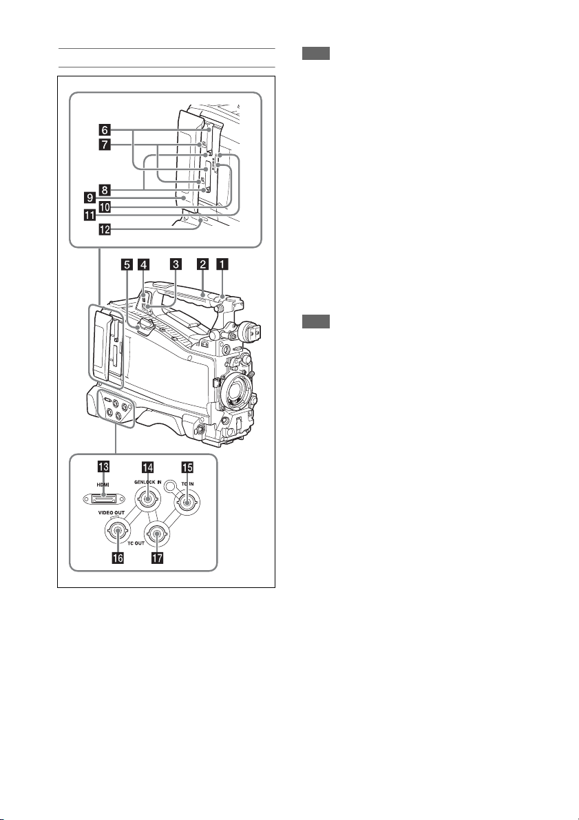
Left side and upper section
a ASSIGNABLE 4/5 switches
You can assign the desired functions to these
switches using Operation >Assignable Switch in
the setup menu (see page 183).
Off is assigned to these switches when the
camcorder is shipped from the factory.
b GPS module
Contains a built-in GPS module.
For details, see“Obtaining Location Information
(GPS)” (page 94).
Note
Do not grasp this part of the camcorder when the GPS
function is in use.
c PC connector
Used to put this camcorder into USB connection
mode and use it as an external storage device for
a computer. When a computer without
ExpressCard slot is connected to this connector,
every memory card inserted in the camcorder is
recognized as a drive on the computer.
d External device connector
Connect to a PSZ-HA/HB/HC series Portable
Storage HDD (option), PSZ-SA25 Portable
Storage SSD (option), a general-purpose external
USB HDD, or USB flash drive to copy clips from
the recording media inserted in an SxS card slot
of the camcorder to USB media.
Note
This connector should be used only for connecting the
type of devices above. It cannot be used for connecting a
USB hub or other devices.
e USB wireless LAN module connector
Connect to IFU-WLM3 USB Wireless LAN
Module (supplied), CBK-WA02 Wireless LAN
Adaptor (option), CBK-NA1 Network Adaptor
(option), or modem (option) to enable
communications with wireless LAN devices and
networks.
It also supports wired communication on a
network by connecting a CBK-NA1 Network
Adaptor (option) and a LAN cable (sold
separately).
For details, see “Connecting Devices using Wireless
LAN” (page 95).
For details, see “Connecting to the Internet”
(page 100).
f SxS memory card slots
These two slots (A and B) can receive SxS
memory cards or other recording media (see
page 68).
g ACCESS indicator
Indicates the state of slots A and B (see page 68).
You can check whether the indicators are lit even
when the slot cover is closed.
21
Page 22

h EJECT (SxS memory card) button
To remove the recording media from the slot,
press the EJECT button to release the lock, then
press the button once more. This makes the media
come out of the slot partially (see page 69).
i Slot cover
Slide to the left and right to open and close.
j PROXY SD card slot
Insert an SD card for recording proxy data.
k ACCESS indicator
Lights up orange when the SD card is being
accessed.
l SLOT SELECT (SxS memory card
select) button
When SxS memory cards are loaded in both card
slots A and B, press this button to select the card
you want to use (see page 69).
m HDMI connector
Connect an HDMI device, such as a monitor or
recording unit, to output HD or SD HDMI video
and audio signals.
n GENLOCK IN (genlock signal input)
connector (BNC type)
This connector inputs a reference signal when the
camcorder is to be gen locked or when timecode is
to be synchronized with external equipment. The
supported reference signals vary depending on
the current system frequency as shown in the
following table.
System frequency Supported reference signals
59.94i 1080/59.94i, 480/59.94i
59.94P 1080/59.94i, 480/59.94i
50i 1080/50i, 576/50i
50P 1080/50i, 576/50i
29.97P 1080/59.94i, 480/59.94i
25P 1080/50i, 576/50i
23.98P 1080/23.98PsF
o TC IN (timecode input) connector
(BNC type)
To apply an external lock to the timecode of the
camcorder, input the reference timecode.
For details, see “Setting the Timecode” (page 61).
p VIDEO OUT connector (BNC type)
Outputs video signals for monitoring.
q TC OUT (timecode output) connector
(BNC type)
To lock the timecode of an external VTR to the
timecode of this camcorder, connect this
connector to the external VTR’s timecode input
connector.
Rear
a TALLY (back tally) indicator (red)
Lights up during recording. It will not light if the
TALLY switch is set to OFF. It also flashes when
the WARNING indicator (see page 18) operates.
The tally indicator on the front of the viewfinder
and the REC indication on the viewfinder screen
light or flash in the same manner.
For details, see “Error/Warning System”
(page 211).
b TALLY switch
Set to ON to activate the TALLY indicator
function.
22
Page 23

c EARPHONE jack (stereo, minijack)
You can monitor the E-E sound during recording
and playback sound during playback. When an
alarm is indicated, you can hear the alarm sound
through the earphone. Plugging an earphone into
the jack automatically cuts off the built-in
speaker.
You can select monaural or stereo using
Maintenance >Audio >Headphone Out in the
setup menu.
Note
Use monaural (2-pole) or stereo (3-pole) type earphones.
Use of other earphones may damage the camcorder.
d AUDIO IN selector switch
Select the audio source you connect to the
AUDIO IN CH1/CH2 connectors.
LINE: When connecting a stereo amplifier or
other external audio signal source
AES/EBU: When connecting an external digital
audio signal source
MIC: When connecting a microphone.
e +48V/OFF (+48V external power
source on/off) switch
Switch between the following settings, according
to the microphone used for audio input.
+48V: Microphone requiring external power
source (phantom power)
OFF: Microphone using internal power source or
not requiring a power source
After adjusting the position, tighten the screws to
secure the cover.
i AUDIO OUT connector (XLR type, 5-
pin, male)
Outputs the audio signals recorded on audio
channels 1 and 2 or audio channels 3 and 4.
The audio signals are selected by the MONITOR
switch.
j REMOTE connector (8-pin)
Connect a remote control unit to control the
camcorder remotely.
Note
Before connecting/disconnecting the Remote Control
Unit to/from the camcorder, be sure to turn off the
camcorder POWER switch.
k SDI OUT 1/2 connectors (BNC type)
Outputs an HD SDI or SD SDI signal (with
embedded audio). The output from this connector
can be turned on or off using Operation >Input/
Output >SDI Out1 Output or >SDI Out2 Output
in the setup menu.
f SDI IN (SDI input) connector (BNC
type)
Connector used when connecting an external HD
SDI signal source to the camcorder.
g AUDIO IN CH-1/CH-2 (audio channel
1 and channel 2 input) connectors (XLR
type, 3-pin, female)
These are audio input connectors for channels 1
and 2 to which you can connect audio equipment
or a microphone.
h Bottom cover
This is provided for protecting the cables
connected to the connectors on the rear panel.
By loosening the screws which retain the cover to
the bottom of the camcorder, you can adjust the
position of the cover depending on the size and
shape of the microphone or audio cable plugs.
23
Page 24
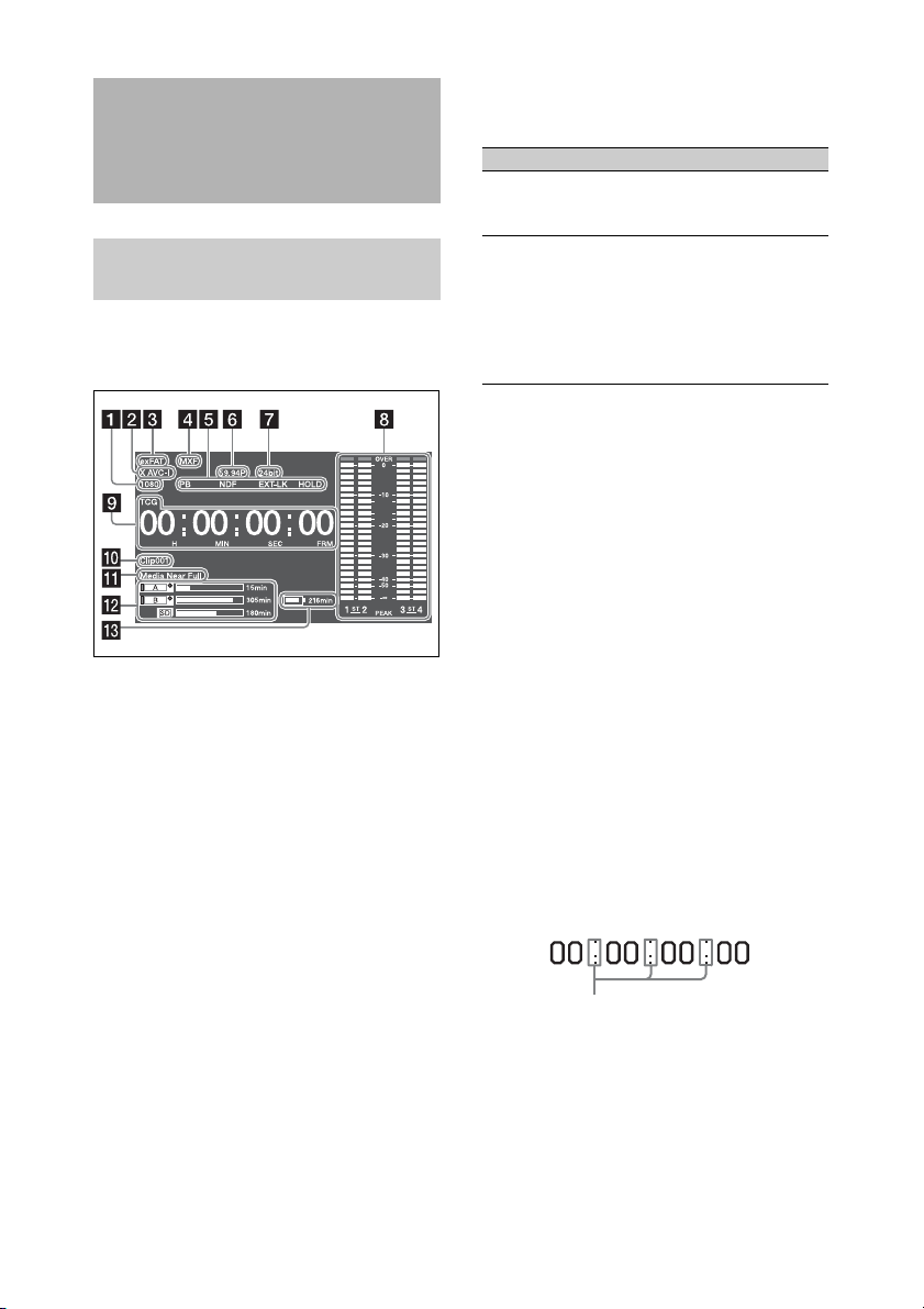
Screen Display
LCD Monitor Information Screen
(Status Display)
The LCD monitor inform ation screen is displayed
by pressing the DISP SEL/EXPAND (display
select/expand) button (see page 18).
dB
a Resolution indicator
Indicates the resolution of the output video.
b Recording format indicator
Indicates the current recording format or the
recording format of clip being currently played.
c File system indicator
d File format indicator
e Status display
PB: Appears during media playback.
NDF: Appears when non-drop-frame timecode is
selected.
EXT-LK: Appears when the internal timecode
generator is locked to an external signal inp ut
to the TC IN (timecode input) connector.
HOLD: Appears when the operation mode of the
internal timecode generator is set to R-RUN
and stopped.
f System frequency indicator
Indicates the system frequency of video being
currently played or recorded.
g Audio format indicator
Indicates the audio recording format or the audio
format of clip being currently played.
Indicator Recording format
16bit • HD420 HQ
• DVCAM
• MPEG IMX 50
24bit • HD422 50
• MPEG IMX 50
•XAVC Intra
• XAVC Long
•SStP
• DNxHD
•ProRes
h Audio level indicators
Indicates the audio recording or playback levels
of channels 1 to 4.
i Time data display
Switches displays of duration, timecode, and user
bits data, depending on the position of the
DISPLAY switch.
Displays the type of data currently shown in the
time data display, as follows.
TCG: Recorded timecode
TCR: Playback timecode
UBG: Recorded user bits
UBR: Playback user bits
CNT: Counter
DUR: Duration
CLK: Time display (when the PRESET/REGEN/
CLOCK switch is set to CLOCK)
When the HOLD button is pressed to hold the
timecode value, the timecode is displayed in the
format shown below. When the HOLD button is
pressed again to release the hold, the timecode is
displayed in the normal format.
The three dots indicates that timecode is
displayed in the hold mode.
j Clip name display
Displays the name of the clip currently recording
when recording, or displays the name of the next
clip to be recorded during recording standby.
k Warning indicator area
Displays warnings when trouble with recording
occurs.
24
Page 25
For details, see “Error/Warning System”
(page 211).
l Remaining media capacity indicator
Shows bar segments indicating the remaining
capacity of recording media in the slots.
m Remaining battery capacity indicator
Displays the battery remaining capacity icon and
the remaining recording time.
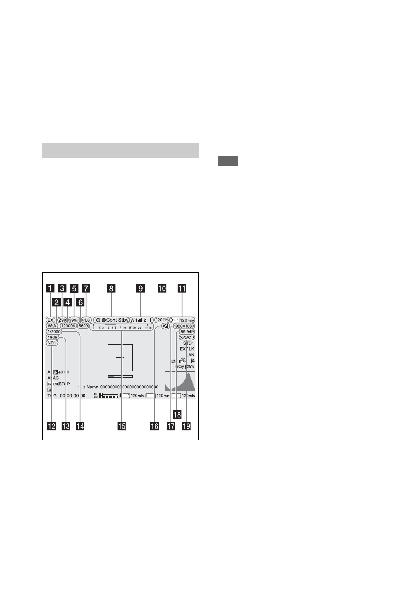
Viewfinder Screen
The viewfinder screen displays images during
shooting (recording or recording standby) and
playback with camcorder information
superimposed on the display.
You can toggle the display of information on/off
using the DISPLAY switch.
The inform ation to display i s linked to the settin gs
in Operation >Super Impose in the setup menu,
and the settings of the corresponding switches.
Display information (top of screen)
EX2D: Appears when both the lens extender
function and digital extender function (2×)
are ON
EX3D: Appears when both the lens extender
function and digital extender function (3×)
are ON
EX4D: Appears when both the lens extender
function and digital extender function (4×)
are ON
Turn the digital extender on/off using an
assignable switch assigned with the Digital
Extender function.
Note
The digital extender cannot be turned on when
Slow & Quick Motion is enabled.
b White balance mode indicator
Displays the currently selected white balance
automatic adjustment memory.
AT W: ATW (Auto Tracing White Balance) mode
W:A : Memory A mode
W:B : Memory B mode
W:C : Memory C mode
W:P : Preset mode
3200K: Appears when an assignable switch
assigned with Color Temp SW 3200K is on
4300K: Appears when an assignable switch
assigned with Color Temp SW 4300K is on
5600K: Appears when an assignable switch
assigned with Color Temp SW 5600K is on
6300K: Appears when an assignable switch
assigned with Color Temp SW 6300K is on
SxSA SxSB Proxy
a Extender indicator
Displays the status of the digital extender
function and lens extender function.
EX: Appears when the lens extender function is
ON
X2D: Appears when the digital extender function
(2×) is ON
X3D: Appears when the digital extender function
(3×) is ON
X4D: Appears when the digital extender function
(4×) is ON
c Zoom position indicator (with lens
mounted)
Displays the zoom position of the zoom lens in
the range 0 to 99.
d Color temperature indicator
Displays the color temperature of the white
balance.
e Focus position indicator (with lens
mounted)
Displays the focus position as a distance to the
subject (unit: meters).
f Electric color temperature filter
indicator
Appears when the CC5600K function is on.
25
Page 26

g Iris position indicator (with lens
mounted)
Displays the iris position setting.
h Recording mode indicator
Displays the following recording operation states
of the camcorder.
Indicator Meaning
zRec During recording
Stby Recording standby
zCont Rec Clip continuous recording in
progress
Cont Stby Recording standby in clip
continuous recording mode
zS&Q Rec Recording in progress in Slow &
Quick Motion mode
S&Q Stby Recording standby in Slow &
Quick Motion mode
zRec Recording in Picture Cache Rec
mode
zCache Recording standby in Picture
Cache Rec mode (z is green)
zInt Rec Recording in progress in Interval
Rec mode
Int Stby Recording standby in Interval Rec
mode
zInt Stby Recording paused in Interval Rec
mode
zSml Rec Recording in progress in Simul
Rec mode
Sml Stby Recording standby in Simul Rec
mode
CALL (red) Call received from external
connected device
Green tally indicator
Indicates when the camcorder is in the following
states.
• Maintenance >Camera Config >HD-SDI
Remote I/F is set to “Green Tally” in the setup
menu and a recording control signal is output
from the SDI OUT connector.
• Green tally signal received (when a camera
adaptor is mounted on the camcorder and a
camera extension unit is connected)
i Wireless receiver function indicator
Displays “W” when a slot-in receiver is attached
to the camcorder, and displays the reception level
for each channel that can be used by the receiver
(1ch, 2ch, or 4ch).
Normal: Displays the strength of the received
signal level by the number of white segment
indicators.
Analog receiver muting/Digital receiver error
rate warning: Displays the strength of the
received signal level by the number of gray
segment indicators.
If the received level exceeds the peak: Displays
“P” in place of the indicator.
1)
If the transmitter is in power-save mode: “S” is
displayed.
Receiver battery is low: The corresponding
channel number and indicators flash.
1) When using the DWR-S02D.
1)
j S&Q Motion (Slow & Quick) frame
rate indicator
Displays the shooting frame rate when the
camcorder is set to Slow & Quick Motion
recording mode.
k Battery capacity/voltage display
Displays th e following indicato rs according to the
type of battery power source.
Battery type Indicator
Info battery Battery remaining
Anton/Bauer battery Remaining battery
Other batteries Input voltage
capacity icon and
remaining recording time
capacity (% indicator)
l ND filter indicator
Displays the position number of the currently
selected ND filter (see page 14).
When “Electrical CC” is assigned to an
assignable switch, the position (A/B/C/D) of the
electrical CC filter is displayed on the right of the
ND filter indicator (1 to 4).
m Gain indicator
Displays the gain setting (dB), set using the
GAIN switch, of the video amplifier.
n Shutter mode/shutter speed indicator
Displays the shutter mode or shutter speed.
For details, see “Setting the Electronic Shutter”
(page 55).
26
Page 27
o Depth of field indicator (serial lens
mounted)
Displays the depth of field using a bar. The units
for display are set using Operation >Display On/
Off >Lens Info in the setup menu, and can be set
to meters or feet.
p GPS indicator
Displays the GPS status.
For details, see “Obtaining Location Information
(GPS)” (page 94).
q Recording format (picture size)
indicator
Displays the picture size of clips recorded onto
SxS memory cards.
r Recording format (system frequency
and scan method) indicator
Displays the currently configured camcorder
system frequency and the recording format scan
method.
s Recording format (codec) indicator
Displays the format name of clips recorded onto
SxS memory cards.
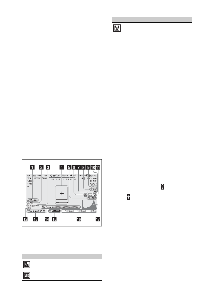
Display information (bottom of screen)
Icon Meaning
Spotlight mode
b ALAC indicator
Displays “ALAC” when the ALAC (Auto Lens
Aberration Correction) function is set to be
performed automatically.
ALAC will be performed automatically when an
ALAC-compatible lens is attached, the ALAC
function is enabled, and Maintenance >Camera
Config >ALAC is set to “Auto” in the setup
menu.
c SDI output REC trigger indicator
Displays the superimposition state of the
recording command sent to the SDI connector
output.
It is displayed when Maintenance >Camera
Config >HD SDI Remote I/F is set to
“Characters” in the setup menu.
d Focus assist indicator
Displays a detection frame (focus area marker)
indicating the area for detection of degree of
focus, and a level bar (focus assist indicator)
indicating the degree of focus within that area.
e Proxy indicator
Displays “Proxy” when proxy recording is on
(Operation >Proxy Recording Mode >Setting in
the setup menu is set to On). During setup,
“Proxy” blinks. “Proxy Rec” is displayed during
proxy file recording. Displays and transfer rate
(%) during proxy file transfer. When transfer
finishes, disappears to indicate 100% transfer.
SxSA SxSB Proxy
a AE (auto iris) mode indicator
Displays the current operating mode of the auto
iris function using an icon and auto iris override
level.
Icon Meaning
Backlight mode
Standard mode
27
Page 28
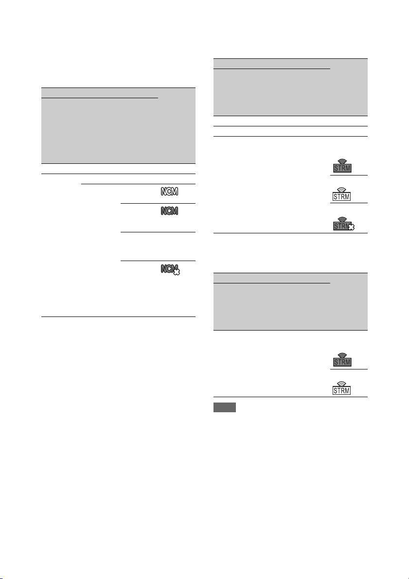
f Network client mode indicator
Displays the status of the connection to the CCM
(Network RX Station configured as Connection
Control Manager) using icons when network
client mode is on.
State Icon
Operation
>Display
On/Off
>NW
Client
Mode
Status
Off – – –
On Off – –
Maintenance
>Network
Client Mode
>Setting
On CCM
State
connected
Connecting to
CCM
(disconnected)
CCM
connection
standby
CCM
connection
error
(flashing)
–
For details
about
errors, see
page 65.
g Streaming indicator
Displays the status of streaming using icons.
State Streaming
Operation
>Display
On/Off
>Streaming
Status
Off – – –
On Off Off –
Maintenance
>Streaming
>Setting
On Off Not
Maintenance
>Network
Client Mode
>Setting
state/Icon
streaming
Streaming
Error
When streaming operations from the CCM is
configured (menu options shown below), the icon
display is as follows.
State Streaming
Operation
>Display
On/Off
>Streaming
Status
On Off On Not
Maintenance
>Streaming
>Setting
Maintenance
>Network
Client Mode
>Setting
state/Icon
streaming
Note
No icon is displayed before streaming starts.
h Timecode external lock indicator
Displays timecode lock when the timecode is
input from an external source.
28
Streaming
Page 29
i Gamma indicator
Displays the gamma setting.
Operation
>Display
On/Off
Menu settings
Paint >Gamma
Gamma Gamma
Category
Indicator
Gamma
Select
>Gamma
Off – – – –
On Off – – Gamma
Off
On STD STD1
STD1
DVW
STD2
STD2
x4.5
STD3
STD3
x3.5
STD4
STD4
240M
STD5
STD5
R709
STD6
STD6
x5.0
HG HG1
HG1
3250G36
HG2
HG2
4600G30
HG3
HG3
3259G40
HG4
HG4
4609G33
User User 1 User 1
User 2 User 2
User 3 User 3
User 4 User 4
User 5 User 5
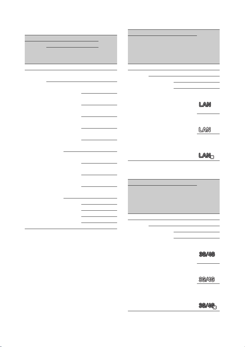
j Wired LAN/Modem connection status
indicator
Displays icons for the wired LAN network or
modem settings/connection status.
Wired LAN settings/connection status
State Network
Operation
>Display
On/Off
Maintenance
>Network
>Setting
Maintenance
>Network
>Wired LAN
connection
state/icon
>Network
Condition
Off – – –
On Off – –
On – –
Disable –
Enable Connecting
to LAN
(flashing)
Connected
to LAN
LAN
connection
error
3G/4G modem settings/connection status
State Network
Operation
>Display
On/Off
Maintenance
>Network
>Setting
Maintenance
>Network
>Modem
connection
state/icon
>Network
Condition
Off – – –
On Off – –
On – –
Off –
On Connecting
to 3G/4G
(flashing)
Connected
to 3G/4G
29
3G/4G
connection
error
Page 30
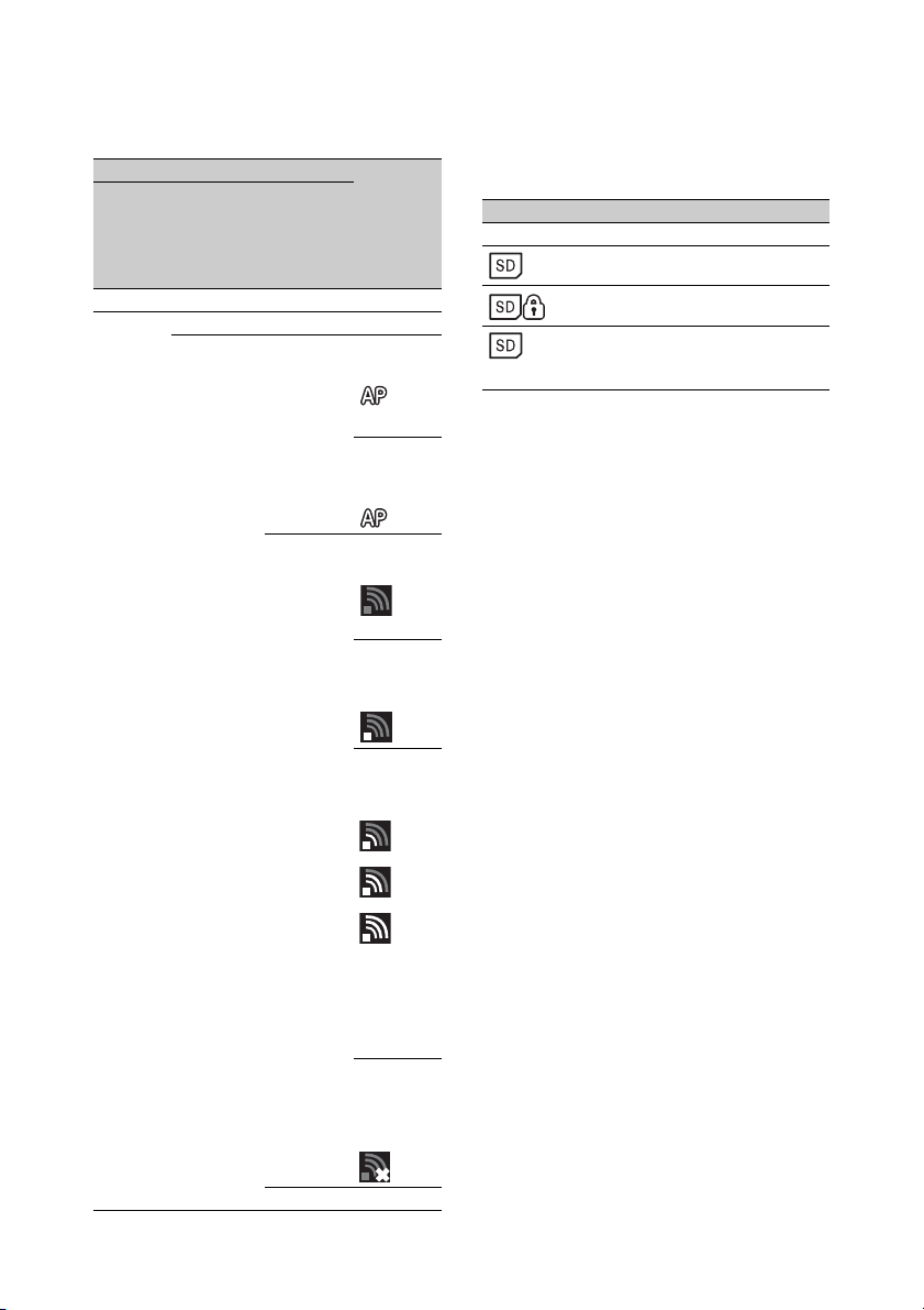
k Wi-Fi mode status indicator
Displays the network setting and connection
status using icons.
State Network
Operation
>Display
On/Off
>Network
Condition
Off – – –
On Off – –
Maintenance
>Network
>Setting
On Wi-Fi
Maintenance
>Network
>Wi-Fi
Mode
Access
Point
Wi-Fi
Station
connection
state/icon
Connecting
to Wi-Fi
(flashing)
Wi-Fi
standby
(connected)
Connecting
to Wi-Fi
(flashing)
Searching
for access
points
Connecting
to access
point
l SD card indicator for saving
configuration data
Displays the state of the SD card (for saving
configuration data) inserted in the UTILITY SD
card slot.
Icon Media state
– SD card not inserted or not mounted
SD card mounted
Mounted SD card is protected
SD card mounting in progress
(flashing)
m Time data display
Displays the remaining recording/playback time,
timecode, user bits, etc., as selected by the
DISPLAY switch (see page 19).
n Clip name display
Displays the name of the clip currently recording
when recording, or displays the name of the next
clip to be recorded during recording standby.
o Audio level meter indicators
Displays the levels of audio channels 1 and 2.
p Recording media state/remaining
capacity indicator for each media slot
Displays the state and remaining capacity of the
media in SxS slot A, SxS slot B, and the PROXY
SD card slot.
If SxS memory cards are inserted in both slots A
and B and the remaining recording time on the
recording SxS memory card falls below 60
seconds, the remaining capacity indicator for the
corresponding slot flashes to indicate that the
camcorder will switch SxS memory cards soon.
Off –
Icon
changes
due to
signal
strength
Access
point
connection
error
30
Page 31

SxS slot icon indicator
Example: SxS slot A (“SxSA”). The icons for
SxS slot B are labeled “SxSB.”
Icon Media state
– Media not inserted or not mounted
Media mounted
Media in use
(flashing)
Recording (active)
(orange bar)
Playback (active)
(green
indicator)
Recording/playback (active)
(orange bar +
green
indicator)
SD card (for proxy data recording) icon
indicator
Icon Media state
– Media not inserted or not mounted
Media mounted
Media mounting
(flashing)
Recording (active)
(orange bar)
The remaining recording time is displayed
numerically.
q Video signal indicator
Displays the output video signal in realtime as a
waveform, vectorscope, or histogram.
31
Page 32

Chapter2 Preparations
Preparing a Power Supply
For safety, use only the Sony battery packs and
AC adaptors listed below.
• BP-FLX75 Lithium-ion Battery Pack
• AC-DN2B/DN10 AC Adaptor
CAUTION
Danger of explosion if battery is incorrectly replaced.
Replace only with the same or equivalent type
recommended by the manufacturer.
When you dispose of the battery, you must obey the law
in the relative area or country.
Using a Battery Pack
When a BP-FLX75 Battery Pack is used, the
camcorder will operate continuously for
approximately 110 minutes.
WARNING
Batteries shall not be exposed to excessive heat such as
sunshine, fire or the like.
Note
The battery pack operating time depends on the
frequency of use of the battery pack, and the ambient
temperature when used.
To attach the battery pack
1 Press the battery pack against the back
of the camcorder, aligning the line on
the side of the battery pack with the
matching line on the camcorder.
1 Battery pack
2 Align the camcorder and battery pack
lines.
2 Slide the battery pack down until its
“LOCK” arrow points at the matching
line on the camcorder.
Before use, charge the battery pack with a charger
suitable for each battery.
For details on the battery charging procedure, refer
to the battery charger operation manual.
Note on using the battery pack
A warm battery pack may not be able to be fully
recharged.
1 “LOCK” arrow
2 Matching line on the camcorder
Note
If the battery pack is not a ttached correctly, the terminals
may become damaged.
32
Page 33

To detach the battery pack
Holding the release button in, pull the battery
pack up.
Release button
Notes
• During recording and playback (while the ACCESS
indicator on the right-side panel is lit in blue and the
ACCESS indicator in the card slot section is lit in
orange), be careful never to remove the battery pack.
Doing so may corrupt the data recorded on the card.
• Make sure to po wer the camcorder off before replacing
the battery pack.
Using AC Power
Mount an AC-DN2B/DN10 on the camcorder in
the same way as a battery pack, then connect to
the AC power supply.
Attaching the Viewfinder
CAUTION
When the viewfinder is attached, do not leave the
camcorder with the eyepiece lens facing the sun.
Direct sunlight can enter through the lens, be focused in
the viewfinder and cause fire.
Note
The viewfinder is supplied separately.
The following procedure is an example for
attaching the HDVF-20A.
For procedures for atta ching other viewfinders, refer
to a manual supplied with each viewfinder.
Attaching the Viewfinder
Note
When attaching the viewfinder, take note of the
following points.
• Be sure to the power off the camcorder before coupling
the viewfinder connector to the camcorder’s VF
connector (20-pin). If you make this connection when
the camcorder power is on, the viewfinder may not
function properly.
• Couple the viewfinder connector firmly to the
camcorder’s VF connector. If the coupling is loose,
noise may appear on the video or the tally light may not
operate properly.
For more information about the connection of the
viewfinder and camcorder, contact a Sony service
representative.
To an AC outlet
1 1 Loosen the viewfinder left-to-right
positioning ring,
viewfinder to the viewfinder
attachment shoe, and 3 tighten the
viewfinder left-to-right positioning
ring.
33
2 attach the
Page 34

Viewfinder left-to-right positioning ring
Adjusting the Viewfinder Position
Slide stopper
2 Couple the viewfinder connector to the
VF connector (20-pin).
VF connector (20-pin)
To adjust the viewfinder left-right position,
loosen the left-right positioni ng ring, and to adjust
the front-back position, loosen the front-to-back
positioning knob.
Viewfinder left-to-right positioning ring
Viewfinder front-to-back positioning knob
(LOCK knob)
Using the BKW-401 Viewfinder
Rotation Bracket
By fitting an optional BKW-401 Viewfinder
Rotation Bracket, you can rotate the viewfinder to
a vertical position so that your leg does not hit the
viewfinder while you are carrying the camcorder
by holding the grip.
Detaching the viewfinder
You can carry out this by following the attaching
procedure in reverse order. But, when detaching
the viewfinder from the attachment shoe, pull up
the stopper.
1 Loosen the front-to-back viewfinder
positioning levers and the front-to-back
viewfinder positioning knobs, and then
pull the viewfinder slide assembly
forward.
34
Page 35

2 Using a 2.5 mm diameter hexagonal
wrench, detach the viewfinder slide
assembly.
Bolts with
hexagonal
hole
Viewfinder slide assembly
3 Attach the BKW-401 with the supplied
bolts.
Detaching the Eyepiece
Removing the eyepiece gives a clearer view of the
screen from further away. It is also easy to
remove dust from the viewfinder screen and
mirror when the eyepiece is detached.
1 Turn the eyepiece locking ring fully
counterclockwise, to align the red
marks on the locking ring and the
viewfinder barrel.
1 Locking ring
2 Locking ring alignment mark
3 Viewfinder barrel alignment mark
2 Detach the eyepiece.
Bolts supplied with the BKW-401
4 Adjust the front-to-back position so
that the arm of the BKW-401 does not
touch the handle when it is raised.
Adjust position so that arm
does not touch handle
Alignment mark on end of eyepiece
You can also attach a commercially available
protection filter, close-up lens, etc. that is
52 mm in diameter.
35
Page 36

To reattach the eyepiece
1 Align the red marks on the eyepiece
locking ring and the viewfinder barrel.
2 Align the red mark on the end of the
eyepiece end with the red marks on the
eyepiece locking ring and the
viewfinder barrel. Then insert the
eyepiece into the viewfinder barrel.
3 Turn the eyepiece locking ring
clockwise until its “LOCK” arrow
points at the red mark on the viewfinder
barrel.
When the eyecup is worn out, replace it with a
new one.
For details about replacement parts, contact a Sony
service representative.
Adjusting the Viewfinder Focus
and Screen
To adjust the viewfinder focus
Turn the diopter adjustment ring until the
viewfinder image is sharpest.
To adjust the viewfinder screen
Adjust the brightness, cont rast, and peaking of the
viewfinder screen with the controls shown below.
Outlines: Adjust using the PEAKING knob.
Contrast: Adjust using the CONTRAST knob.
Brightness: Adjust using the BRIGHT knob.
1 PEAKING knob
2 CONTRAST knob
3 BRIGHT knob
Diopter adjustment ring
36
Page 37

Using the Camcorder for the First Time
When using the camcorder for the first time,
configure the following settings in the menu.
For details about menu operations, see “Basic Setup
Menu Operations” (page 133).
Setting the time zone
Set the time zone for the region of use. The
default value is “UTC Greenwich.”
5 Press the SET button.
The internal clock is set to the date set in
steps 2 to 4.
Next, set the time.
6 Select Maintenance >Clock Set >Time
in the setup menu.
The Time screen appears.
1 Select Operation >Time Zone >Time
Zone in the setup menu.
2 Select the time zone to use.
Setting the date and time of the internal
clock
Set the year, month, day, and day-of-week of the
internal clock.
1 Select Maintenance >Clock Set >Date in
the setup menu.
The Date screen appears.
2 Turn the MENU knob to select the year,
month, or day, and then press the knob.
The selected year, month, or day becomes
editable.
3 Turn the MENU knob to set the year,
month, or day, and then press the knob.
7 Set the time in the same way as when
setting the date.
8 Press the SET button.
The time is registered in the internal clock.
To cancel the setting
Press the Cancel button.
4 Repeat steps 2 and 3 to set the
remaining digits.
37
Page 38

Mounting and Adjusting the Lens
Note
Always power the camcorder off before mounting or
removing a lens.
For information about using the lens, refer to the
operation manual for the lens.
Note
The lens is supplied separately.
Lens mount
securing rubber
Caution
If the lens is not firmly locked, it may come off
while the camcorder is being used. This could cause
a serious accident. Make sure the lens is firmly
locked. It is recommended that the lens mount
securing rubber be put on the lens locking lever as
illustrated above.
4 Connect the lens cable to the LENS
connector.
5 Secure the lens cable with the cable
clamp.
If you have attached an aberration correction
lens
The aberration correction function is activated
automatically.
aberration correction lens may require more time
than normal because of data loading at start-up.
Contact a Sony service representative for
information about aberration correction lenses.
1) The aberration correction function does not operate if
Maintenance >Camera Config >ALAC in the setup
menu is set to Off.
Adjusting the Flange Focal Length
If the lens does not stay in focus properly as you
zoom from telephoto to wide angle, adjust the
flange focal length (the distance from the plan e of
the lens mounting flange to the imaging plane).
Make this adjustment just one time after
mounting or changing the lens.
When carrying out the adjustment, use a flange
focal length adjustment chart as the subject.
1)
Starting the camcorder with an
1 Push the lens locking lever up and
remove the lens mount cap from the
lens mount.
2 Align the center pin on the lens with the
center slot in the lens mount, and insert
the lens into the mount.
3 Holding the lens in place, push the lens
locking lever down to lock the lens.
About 3 m (10 ft)
38
Page 39

Carrying out the adjustment
1 Set the iris to manual.
2 Open the iris, position the supplied
flange focal length adjustment chart
approximately 3 meters (10 ft) away
from the camcorder, and arrange the
lighting to obtain a satisfactory video
output.
3 Loosen the fixing screws on the F.f or
F.B ring (flange focal length adjustment
ring).
4 Use manual or power zoom to set the
lens to telephoto.
5 Point the camcorder at the chart by
turning the focus ring and focus on it.
6 Set the zoom ring to wide angle.
7 Turn the F.f or F.B ring until the chart
is in focus, being careful not to disturb
the focus ring.
8 Repeat steps 4 to 7 until the chart stays
in focus all the way from wide angle to
telephoto.
Preparing the Audio Input System
Connecting a Microphone to the
MIC IN Connector
You can attach the optional ECM-680S stereo
microphone to the microphone holder of the
viewfinder (optional).
The following procedure is an example for
attaching a microphone holder to the HDVF-20A.
For procedures for attaching a mi crophone holder to
other viewfinders, refer to the manual supplied with
each viewfinder.
1 Loosen the screw and open the
microphone holder clamp.
Microphone holder clamp
9 Tighten the F.f or F.B ring fixing
screws.
2 Place the microphone in the
microphone holder.
1 Place the microphone in the holder so
that “UP” is at the top.
2 Close the microphone holder.
3 Tighten the screw.
39
Page 40

Connecting Microphones to the
AUDIO IN Connectors
You can connect up to two monaural
microphones to the AUDIO IN CH-1/CH-2
connectors, using an optional CAC-12
Microphone Holder.
The following is the procedure for attaching an
electret condenser microphone such as the ECM674/678.
On how to attach the CAC-12, refer to the operation
manual for the CAC-12.
1 Attach the electret condenser
microphone.
On how to perform this operation, refer to the
operation manual for the microphone.
3 Plug the microphone cable into the MIC
IN connector, then set the AUDIO IN
switch for the channel on which you
want to record the audio from this
microphone to FRONT.
4 Secure the microphone cable with the
cable clamp.
1 Loosen the ball joint lock lever.
2 Place the microphone in the holder so
that “UP” is at the top.
3 Close the microphone holder.
4 Tighten the screw.
5 Position so that the microphone does
not interfere with the viewfinder and
tighten the ball joint lock lever.
Microphone
40
Page 41

2 Connect the microphone cable to the
AUDIO IN CH-1 or CH-2 connector.
3 Set the switches as follows.
• Set the AUDIO IN switch to the MIC
position.
• Set the +48V/OFF switch as follows,
according to the type of microphone used.
Internal power supply: OFF
External power supply: +48V
• Set the AUDIO IN CH1/CH2 switch for the
channel to which the microphone is
connected to REAR.
1 AUDIO IN selector switch
2 Monaural microphone
3 AUDIO IN CH1/CH2 switches
4 To AUDIO IN CH-1 or CH-2 connector
Attaching a Portable Wireless
Tuner (for use with wireless
microphone)
To use a wireless microphone, power the
camcorder off and then attach one of the
following portable wireless tuners.
• DWR-S02D Digital Wireless Receiver
• WRR-855S UHF Synthesized Tuner Unit
• WRR-860A/861/862/URX-S03D UHF
Synthesized Diversity Tuner
Refer to the operation manual for the portable
wireless tuner.
Note
The optional WRR Mount Bracket (service part number:
A-8278-057-B) is required to fit the WRR-862.
For details, contact your vendor or a Sony service
representative.
To fit the DWR-S02D, WRR-855S, or
URX-S03D
1 Remove the four fixing screws holding
the cover of the portable tuner/receiver
housing slot located in the rear of the
camcorder to remove the cover.
4 Switch the input level to match the
sensitivity of the microphone used.
Switch the input level b y changing the setting
of Maintenance >Audio >Rear MIC >CH1/
CH2 Ref in the setup menu (factory default
setting is –60dB). For details, see page 165.
Notes
• If the input level on the camcorder is not at an
appropriate setting for the microphone se nsitivity, loud
sounds may be distorted, and the signal-to-noise ratio
may be affected.
• In order for the AUDIO IN CH-1 and CH-2 connectors
on the camcorder to be able to provide a phantom 48 V
power supply, female XLR connectors (3-pin) are
fitted. If the microphone cable has a female connector,
use an adaptor.
• When detaching the CAC-12 Microphone Holder,
attach the screws used for mounting the holder back
into their original places.
2 Insert the DWR-S02D, WRR-855S, or
URX-S03D into the housing slot, and
fasten the four fixing screws.
41
Page 42

DWR-S02D, WRR-855S, or URX-S03D
BP-L80S
Adjustment
screws
Mount plate
(supplied with
WRR-862)
3 Set the AUDIO IN selector for the
channel to which you want to input
audio signal to WIRELESS (see
page 20).
To fit the WRR-862 (when using a BPL80S Battery Pack)
1 Attach the WRR tuner fitting (not
supplied; service part number: A-8278057-B) to the back of the camcorder.
1 Use a Phillips type screwdriver to
tighten the four screws placed in the
tuner fitting.
Note
Make sure that all four screws are fully tightened.
2 Loosen the adjustment screws on the
tuner fitting.
3 Adjust the tuner fitting position for a
BP-L80S Battery Pack to be attached,
and tighten the adjustment screws to
fix its position.
4 Attach the mount plate supplied with
the WRR-862.
About the WRR tuner fitting (service part
number: A-8278-057-B), cont act a Sony service
or sales representative.
Phillips type
screwdriver
2 Attach the battery pack.
On how to attach the battery pack, see “To
attach the battery pack” (page 32).
3 Mount the tuner on the WRR tuner
fitting.
WRR-862
4 Connect the tuner power cord to the DC
OUT connector of the camcorder, and
the audio output cable to the AUDIO IN
CH-1 or CH-2 connector.
5 Set the switches as follows.
• Set the AUDIO IN selector for the channel
to which the audio output cable is attached
to MIC.
• Set the AUDIO IN CH1/CH2/CH3/CH4
switch for the channel to which the audio
output cable is connected to REAR.
If the XLR connection automatic detection
function is on, the input signal for audio
recording is selected automatically, and
therefore this setting is not required.
42
Page 43

The XLR connection automatic detection
function can be switched on or off by
Maintenance >Audio >Rear XLR Auto in the
setup menu.
1 AUDIO IN CH1/CH2 switches
2 To DC OUT connector
3 To AUDIO IN CH-1 or CH-2
connector
4 AUDIO IN selector switch
Connecting Line Input Audio
Equipment
Connect the audio output connector of the audio
equipment that supplies t he line input signal to the
AUDIO IN CH-1 or CH-2 connector.
Switch settings
Set the AUDIO IN selector for the channel to
which the audio signal source is connected to
LINE.
Selecting the audio inputs to be recorded
• With the XLR connection automatic detection
function switched off (the factory default
setting): A signal must be selected for audio
recording by setting the AUDIO IN CH1 or
CH2 switch to REAR depending on which of
the AUDIO IN CH-1 and CH-2 connectors is
used for connecting the external audio
equipment.
• With the XLR connection automatic detection
function switched on: When a cable is
connected to the AUDIO IN CH-1 or CH-2
connector, the input from that connector is
automatically selected for audio recording,
regardless of the setting of the AUDIO IN CH1
or CH2 switch.
1 AUDIO IN CH1/CH2 switches
2 To AUDIO IN CH-1 or CH-2 connector
3 Audio equipment
4 AUDIO IN selector switch
43
Page 44

Tripod Mounting
1 Attach the optional VCT-14/U14
Tripod Adaptor to the tripod.
Tripod attachment
Camera mount
2 Mount the camcorder on the tripod
adaptor.
To remove the camcorder from the tripod
adaptor
Hold down the red button and pull the lever in the
direction of the arrow.
Red button
Lever
Note
The tripod adaptor pin may remain in the engaged
position even after the camcorder is removed. If this
happens, press the red button and move the lever as
shown above until the pin returns to the stowed position.
If the pin remains in the engaged position, you will not
be able to mount the camcorder on the tripod adaptor.
Slide the camcorder forward along the
groove in the adaptor until it clicks.
3 Move the camcorder forward and
backward, and make sure it does not
detach.
44
Page 45

Connecting a Video Light
Using the Shoulder Strap
With this camcorder, you can use the Anton
Bauer Ultralight 2 or equivalent video light
(powered by 12 V with maximum power
consumption of 50 W).
• If you connect the video light to the LIGHT
connector on the camcorder and set the LIGHT
switch to AUTO, you can turn the light on and
off automatically a s you start and stop recording
on this camcorder.
• The output of the LIGHT connector on the
camcorder is regulated to 12 V even when the
camcorder is supplied with over 12 V power
(through the DC IN connector or battery pack).
The brightness or color temperature of the light
will not change in response to voltage increase.
Notes
• Do not connect video lights with power consumption
of 50 W or greater.
• The brightness or color temperature of the light will
change when the voltage (supplied through the DC IN
connector or from the battery pack) is less than 12 V.
To attach the video light
Fit the video light to the accessory shoe on the
camcorder grip, and connect the video light cable
to the LIGHT connector.
Note
The accessory shoe on the camcorder is of the 1/4-inch
screw type. If you want to replace this with a slide-type
shoe, use the supplied cold shoe kit.
To attach the shoulder strap
1 Fit one of the clips to a shoulder strap
fitting.
Pull up the strap to lock the fitting.
Clip
2 Fit the other clip to the shoulder strap
fitting on the other side of the grip in the
same way.
45
Page 46

To remove the shoulder strap
Press here and pull in the direction
shown by the arrow to release.
Adjusting the Shoulder Pad Position
You can slide the shoulder pad back and forth
within a 40 mm range. This adjustment helps you
get the best balance for shooting with the
camcorder on your shoulder.
Shoulder pad
1 Raise the lever in the center of the
shoulder pad to unlock the shoulder
pad.
2 Slide the shoulder pad backward or
forward until it is in the most
convenient position.
3 Bring down the lever to lock the
shoulder pad in the selected position.
46
Page 47

Chapter3 Adjustments and Settings
For menu operations, see “Basic Setup Menu Operations” (page 133).
Setting the Video Format
System frequency
(Operation >Format
>Frequency in setup
menu)
59.94/50 Yes – – XAVC-I 1080P 1920×1080
File system
(Operation >Format
>File System in setup
menu)
exFAT UDF FAT
Yes – – XAVC-I 1080i
Yes – – XAVC-I 720P 1280×720
Yes – – XAVC-L 50 1080P 1920×1080
Yes – – XAVC-L 50 1080i
Yes – – XAVC-L 50 720P 1280×720
Yes – – XAVC-L 35 1080P 1920×1080
Yes – – XAVC-L 35 1080i
Yes – – XAVC-L 25 1080i
Yes Yes – HD422 50 1080i 1920×1080
Yes Yes – HD422 50 720P 1280×720
Yes Yes Yes HQ 1920×1080i 1920×1080
Yes Yes Yes HQ 1440×1080i 1440×1080
Yes Yes Yes HQ 1280×720P 1280×720
– – Yes SP 1440×1080i 1440×1080
Ye s – –
Ye s – –
Ye s – –
Ye s – –
Ye s – –
Yes Yes – MPEG IMX 50 720×486/720×576
Yes Yes – DVCAM 720×480/720×576
Video format
(Operation >Format
>Rec Format in setup
menu)
SStP SR-Lite 422
DNxHD 220x 1080i
DNxHD 145 1080i
ProRes 422 HQ 1080i
ProRes 422 1080i
c)
a) c)
a) c)
b) c)
b) c)
Picture size
1920×1080
1920×1080
1920×1080
47
Page 48

System frequency
(Operation >Format
>Frequency in setup
menu)
File system
(Operation >Format
>File System in setup
menu)
Video format
(Operation >Format
>Rec Format in setup
menu)
Picture size
exFAT UDF FAT
29.97/25/23.98 Yes – – XAVC-I 1080P 1920×1080
Yes – – XAVC-L 50 1080P 1920×1080
Yes – – XAVC-L 35 1080P
Yes Yes – HD422 50 1080P 1920×1080
Yes Yes – HD422 50 720P 1280×720
Yes Yes Yes HQ 1920×1080P 1920×1080
Ye s – –
Ye s – –
Ye s – –
Ye s – –
Ye s – –
a) When using PXWK-502 Codec Option
b) When using PXWK-501 Codec Option
c) Not supported for proxy recording and wireless LAN connection function.
SStP SR-Lite 422
DNxHD 220x 1080P
DNxHD 145 1080P
ProRes 422 HQ 1080P
ProRes 422 1080P
c)
a) c)
b) c)
a) c)
b) c)
1920×1080
1920×1080
1920×1080
SDI OUT connector, HDMI output connector, and VIDEO OUT connector output formats
The signals that can be output from the SDI OUT connector, HDMI output connector, and VIDEO OUT
connector are shown in the following table according to the Operation >Format setting in the setup menu.
Operation menu VIDEO OUT signal format
Format Input/Output
Frequency Rec Format
(codec omitted)
59.94 1920×1080 P 1920×1080P
1920×1080 i 1920×1080i 1920×1080i HD-Y HD-Y
1440×1080 i 1920×1080i 1920×1080i HD-Y HD-Y
1280×720 P 1280×720P 1280×720P HD Sync
720×480 i 720×486i 720×480i Composite
Output Format Proxy recording/Wireless
LAN connection function
SDI HDMI OFF ON
1920×1080P HD-Y
HD-Y
(Level A)
1920×1080P
No signal HD-Y
HD-Y
(Level B)
1920×1080i 1920×1080i HD-Y HD-Y
a)
f) g)
f) g)
f) g)
f) g)
f) g)
f) g)
Composite
Composite
–
HD Sync
Composite
Composite
HD-Y
720×486i 720×480i Composite
720×486i 720×480i Composite
720×486i
c)
720×480i
c)
Composite
720×486i 720×480i Composite
No signal 720×480P Composite
d)
d)
a)
d)
d)
48
Page 49

Operation menu VIDEO OUT signal format
Format Input/Output
Frequency Rec Format
(codec omitted)
Output Format Proxy recording/Wireless
LAN connection function
SDI HDMI OFF ON
29.97 1920×1080 P 1920×1080PsF 1920×1080i HD-Y
720×486i 720×480i Composite
1280×720 P 1280×720P 1280×720P HD-Y
720×486i 720×480i Composite
23.98 1920×1080 P 1920×1080PsF No signal HD-Y
1920×1080i
(2-3PD)
720×486i
(2-3PD)
1280×720 P 1280×720P
(2-3PD)
720×486i
(2-3PD)
50 1920×1080 P 1920×1080P
1920×1080i
HD-Y
(2-3PD)
720×480i
Composite
(2-3PD)
1280×720P
HD-Y
(2-3PD)
720×480i
Composite
(2-3PD)
1920×1080P HD-Y HD-Y
f)
f) g)
b) f)
f) g)
f)
e) f) g)
f) g)
b) f)
f) g)
f)
HD-Y
Composite
b) f)
HD-Y
Composite
f)
HD-Y
f) g)
HD-Y
Composite
b) f)
HD-Y
Composite
d)
d)
d)
d)
(Level A)
1920×1080P
No signal HD-Y HD-Y
(Level B)
1920×1080i 1920×1080i HD-Y HD-Y
720×576i 720×576i Composite
f) g)
Composite
d)
1920×1080 i 1920×1080i 1920×1080i HD-Y HD-Y
720×576i 720×576i Composite
f) g)
Composite
d)
1440×1080 i 1920×1080i 1920×1080i HD-Y HD-Y
c)
720×576i
1280×720 P 1280×720P 1280×720P HD Sync
720×576i 720×576i Composite
720×576 i 720×576i 720×576i Composite
No signal 720×576P Composite
25 1920×1080 P 1920×1080PsF 1920×1080i HD-Y
720×576i 720×576i Composite
1280×720 P 1280×720P 1280×720P HD-Y
720×576i 720×576i Composite
720×576i
c)
Composite
f)
b) f)
a)
f) g)
f) g)
f) g)
f) g)
f) g)
f) g)
–
HD Sync
Composite
Composite
HD-Y
f)
HD-Y
Composite
b) f)
HD-Y
Composite
a)
d)
d)
d)
d)
a) 1080i sync signal output.
b) 1080PsF signal output.
c) Switches to 1920×1080i when proxy recording or wireless LAN connection function is on.
d) Character information (superimposed) turns on/off in sync with the SDI OUT2/HDMI character information display
switching.
e) HD Sync, when Apple ProRes or Avid DNxHD® is selected.
f) Character information (superimposed) turns on/off in sync with the SDI OUT2 connector output on/off setting when
SStP, Apple ProRes, or Avid DNxHD® is selected.
g) Character information (superimposed) turns on/off in sync with the SDI OUT2 connector output on/off setting when
SStP is selected.
49
Page 50

Note
Observe the following when the recording format is XAVC-L and 1080/59.94P or 50P is selected.
• Enabling the Picture Cache Rec function prevents switching between SDI output Level-A and other output formats.
• When Level A is selected, there are cases where On/Off switching of the SDI Out Output item may not be available.
To change settings, first disable the Picture Cache Rec function and then change the settings.
50
Page 51

Selecting the File System
Switching the Video Format
You can select the file system.
1 Select Operation >Format >File System
in the setup menu.
2 Turn the MENU knob to select a file
system, then press the knob.
A confirmation screen appears.
3 Select [Execute] to execute, or select
[Cancel] to cancel, and then press the
MENU knob.
The camcorder will reboot automatically
after using Execute.
Note
The file system cannot be changed during recording/
playback or while the thumbnail screen is displayed.
Switching the System Frequency
You can switch the system frequency as required.
1 Select Operation >Format >Frequency
in the setup menu.
2 Turn the MENU knob to select the
system frequency, and press the knob.
A confirmation screen appears.
You can switch the video format as required.
1 Sel ect Operation >Format > Rec Format
in the setup menu.
2 Turn the MENU knob to change the
video format, and press the knob.
A confirmation screen appears.
3 Select [Execute] to execute, or select
[Cancel] to cancel, and then press the
MENU knob.
3 Select [Execute] to execute, or select
[Cancel] to cancel, and then press the
MENU knob.
The camcorder will reboot automatically
after using Execute.
Notes
• The system frequency cannot be changed during
recording/playback or while the thumbnail screen is
displayed.
• After switching between 29.97 and 59.94 or between
25 and 50, the camcorder does not reboot
automatically.
51
Page 52

Adjusting the Black Balance and White Balance
To ensure excellent im age quality when using this
camcorder, conditions may require that both the
black balance and the white balance be adjusted.
Black balance and white balance adjustment
values that are automatically set by the camcorder
and the various settings are stored in the
camcorder memory and retained even when the
power is turned off.
Adjusting the Black Balance
The black balance will require adjustment in the
following cases.
• Using the camcorder for the first time
• When the camcorder has not been used for a
long time
• When the camcorder is used under conditions in
which the surrounding temperature has changed
greatly
• When the GAIN switch (L/M/H/Turbo) values
have been changed using Operation >Gain
Switch in the setup menu.
It is not usually necessary to adjust the black
balance when using the camcorder after it has
been off.
In automatic black balance mode, adjustments are
performed in the following order: black set and
black balance. Manual black balance adjustment
can be selected from the setup menu.
Automatic black balance adjustment is disabled
in the following cases.
• During recording
• During special recording modes
• When the shutter mode is SLS
1 Set the OUTPUT/DCC switch to CAM.
2 Push the AUTO W/B BAL switch to
BLACK and release the switch.
The message “Executing…” appears during
execution, and changes to “OK” when the
adjustment finishes.
Adjustment values are saved to memory
automatically.
Notes
• During the black balance adjustment, the iris is
automatically closed.
• During the black balance adjustment, the gain
selection circuit is automatically activated so you may
see flickering on the viewfinder screen, but this is not
a fault.
If automatic black balance adjustment
cannot be made
If the black balance adjustment cannot be
completed normally , an error message will a ppear
for about three seconds on the viewfinder screen.
Possible messages are listed below.
Error message Meaning
NG: Iris not Closed The lens iris did not close;
adjustment was impossible.
NG: Timeout Adjustment could not be
completed within the
standard number of
attempts.
NG: Out of Range Value could not be adjusted
because the difference
between the current value
and reference value exceeds
the adjustment range.
If any of the above error messages is displayed,
retry the black balance adjustment.
If the error message occurs again, an internal
check is necessary.
For information about this internal check, refer to
the Maintenance Manual (option).
Note
If the lens cable is not firmly connected to the LENS
connector, it may not be pos sible to adjust the lens ir is. If
this happens, the black balance will be incorrect.
52
Page 53

Adjusting the White Balance
Always readjust the white balance when the
lighting conditions change.
1 Set the switches and selectors as shown
below.
• GAIN switch: L (set to a gain value that is
as small as possible)
• OUTPUT/DCC switch: CAM
• WHITE BAL switch: A or B
1) Adjustment values are saved to memory B only
when Operation >White Setting >White
Switch<B> in the setup menu is set to [Memory].
1)
2 Set the FILTER knob to suit the
lighting conditions as follows.
3 Place a white test card under the same
lighting conditions as the subject to be
shot and zoom in on it.
Alternatively, any white object such as a
cloth or a wall can be used.
The absolute minimum white area is as
follows.
Rectangle centered on the screen.
The lengths of the sides are 70% of the
length and width of the screen.
10% or more of the surface area of the
image within the rectangular area must
be white.
Note
Make sure there are no bright spots in the rectangle.
4 Adjust the lens iris.
Manually adjusted lens: Set the iris to an
appropriate setting.
Lens with automatic iris: Set the automatic/
manual switch on the lens to automatic.
5 Push the AUTO W/B BAL switch to
WHITE and then release the switch.
The message “Executing…” appears during
execution, and changes to “OK: (color
temperature of subject)” when the
adjustment finishes.
The adjustment values are saved
automatically in the memory selected in step
1 (A or B).
Note
If the camcorder has a zoom lens with an automatic
iris, the iris may hunt
prevent this, adjust the iris gain knob (indicated as
IG, IS, or S) on the lens.
For details, refer to the lens operation manual.
1) Hunting: Repeated brightening and darkening of
the image, resulting from repeated response to
automatic iris control.
If the automatic white balance
adjustment cannot be made
If the white balance adjustment cannot be
completed normally , an error message will a ppear
for about three seconds on the viewfinder screen.
Possible messages are listed below.
Error message Meaning
NG: Low Light The white video level is too low.
NG: Timeout Adjustment could not be
NG: High Light The white video level is too
NG: Color Temp.
High
NG: Color Temp.
Low
NG: Out of
Range
1)
during the adjustment. To
Either open the lens iris or
increase the gain.
completed within the standard
number of attempts.
high. Either stop down the lens
iris or change the ND filter.
The color temperature of the
subject lighting is too high, and
could not be adjusted. Adjust
the color temperature of the
lighting, then update memory.
The color temperature of the
subject lighting is too low, and
could not be adjusted. Adjust
the color temperature of the
lighting, then update memory.
Value could not be adjusted
because the difference between
the current value and reference
value exceeds the adjustment
range.
53
Page 54

Error message Meaning
NG: Poor White
Area
If any of the above error messages is displayed,
retry the white balance adjustment. If the error
message occurs again, an internal check is
necessary.
For information about this internal check, refer to
the Maintenance Manual.
The white surface of the subject
is too narrow, and could not be
adjusted.
If you have no time to adjust the white
balance
Set the WHITE BAL switch to PRST.
2 Select the position to which to assign a
CC filter by selecting one of [Electrical
CC<A>] to [Electrical CC <D>], and
then turn the MENU knob to select the
desired color temperature.
To set no color temperature
Select “-----” with Electrical CC<C> or <D>
selected.
When the assignable switch is pressed, the
setting for that position is not displayed. For
example, if “-----” is set for one position, then
switching between the remaining three
positions is carried out.
3 Repeat step 2 as required.
To change the color temperature when
the ND filter is switched
You can assign electrical CC (color correction)
filters to ND filters (see page 14) allowing you to
change the color temperature automatically when
the ND filter is switched.
1 Set Maintenance >White Filter >ND
Filter C.Temp to On in the setup menu
(see page 171).
2 To assign an electrical CC filter to
FI LT ER k nob pos iti on n um ber 1, select
[ND FLT C.Temp<1>]. To assign it to
positions 2 to 4, select [ND FLT
C.Temp<2–4>].
3 Turn the MENU knob to select the
desired color temperature.
4 Repeat steps 2 and 3 as required.
To switch between electrical CC filters
with an assignable switch
You can assign the function that switches
between electrical CC filters to an assignable
switch. This allows you to switch between color
temperatures (3200K/4300K/5600K/6300K) that
have been assigned using up to four positions (A
to D) with each press of the assignable switch.
4 Assign the electrical CC filter switching
function (ELECTRICAL CC) to an
assignable switch (see page 182).
White balance memory
Values stored in memory are held until the white
balance is next adjusted, even if the camcorder
power is turned off.
The camcorder has two white balance memories,
A and B. You can automatically save adjustment
values for each ND filter in the memory that
corresponds to the WHITE BAL switch setting
(A or B). The camcorder has four built-in ND
filters, allowing you to save a total of eight
adjustment values (4×2). However, the contents
of the memories are not linked to ND filter
settings in the following case.
• When the number of memories allocated to
each of A and B is limited to one by setting
Operation >White Setting >Filter White
Memory in the setup menu to Off.
Also, when Operation >White Setting >White
Switch<B> in the setup menu is set to [ATW
(Auto Tracing White Balance)], and the WHITE
BAL switch is set to B, the ATW function is
activated to automatically adjust the white
balance of the picture being shot for varying
lighting conditions.
1 Select Maintenance >White Filter in the
setup menu.
54
Page 55

Setting the Electronic Shutter
Shutter Modes
The shutter modes that can be used with the
electronic shutter and the shutter speeds that can
be selected are listed below.
Note
When a remote control unit, such as the RM-B170, is
connected, only standard mode (Speed) can be selected.
Standard mode
Select this mode for shooting fast-moving
subjects with little blurring.
You can set the shutter speed in one of two shutter
modes: Speed mode, in which the speed is set in
seconds, and Angle mode, in which the speed is
set in degrees.
Speed mode
System
frequency
59.94i
59.94P
50i
50P
29.97P
25P
23.98P
a) This speed cannot be selected when the camcorder is
in Slow & Quick Motion mode and Operation >Rec
Function >Frame Rate in the setup menu is set to a
value that is greater than the system frequency.
Angle mode
180°, 90°, 45°, 22.5°, 11.25°
Shutter speed (unit: seconds)
1
/60, 1/
, 1/
, 1/
, 1/
100
, 1/
a), 1
, 1/
a), 1
, 1/
a), 1
, 1/
, 1/
1000
/
50
250
/
50
250
/
48
120
2000
, 1/
a), 1
, 1/
a), 1
, 1/
a), 1
, 1/
120
2000
/60, 1/
500
/60, 1/
500
/
125
, 1/
, 1/
50
, 1/
1
/
500
1
/
40
1
/
125
1
/
33
1
/
125
1
/
32
1
/
100
1
/
1000
125
1000
1000
a), 1
250
250
, 1/
100
, 1/
, 1/
100
, 1/
/60, 1/96,
, 1/
500
,
120
2000
120
2000
,
,
,
ECS (Extended Clear Scan) mode
Select this mode for obtaining images with no
horizontal bands of noise when shooting subjects
such as monitor screens.
As shown in the following tables, the range of
shutter speeds that can be set varies depending on
whether the Slow & Quick Motion (S&Q)
function is on or off.
System
frequency
Shutter speed (unit: Hz)
S&Q: Off S&Q: On
59.94i 60.00 to 7000 –
59.94P 60.00 to 8000 60.00 to 8000
29.97P 30.00 to 8000 30.00 to 8000
23.98P 23.99 to 6000 30.03 to 6000
50i 50.00 to 7000 –
50P 50.00 to 7000 50.00 to 7000
25P 25.02 to 7000 30.00 to 7000
SLS (slow speed shutter) mode
This mode is used to shoot subjects with low
illumination. The number of accumulated frames
shot when using the slow speed shutter function
can be set to 2, 3, 4, 5, 6, 7, 8, 16 using Operation
>Slow Shutter >Number of Frames in the setup
menu.
Notes
• SLS mode cannot be used when the camcorder is in
Slow & Quick Motion mode.
• It is not possible to turn the SLS mode on or off, or
change the number of accumulated frames when
recording.
Selecting the Shutter Mode and
Shutter Speed
Notes
• When the automatic iris is used, the iris opens wider as
the shutter speed increases, thus reducing the depth of
field.
• The selectable shutter speeds vary depending on the
current system frequency.
To switch between Speed mode and
Angle mode
1 Select Operation >Shutter >Mode in the
setup menu.
55
Page 56

2 Turn the MENU knob to select [Speed]
or [Angle], and then press the knob.
To set the shutter mode and standardmode shutter speed
Once the shutter speed is selected, it is retained
even when the camcorder power is turned off.
1 Push the SHUTTER switch from ON to
SELECT.
The current shutter setting indication appears
in the viewfinder for about three seconds.
2 Before the shutter setting in step 1
disappears, push the SHUTTER switch
down to SELECT again. Repeat this
step until the desired mode or speed
appears.
When all modes and speeds are displayed,
the display changes in the following order.
Speed Mode (with system frequency 59.94i)
ECS Mode
Note
Depending on the frame rate setting (see page 80), some
shutter speeds cannot be selected in Slow & Quick
Motion mode. These speeds are replaced by the slowest
selectable shutter speed.
Example: When shooting in XAVC-I 1080P/29.97P,
frame rate of 60, and Slow & Quick Motion
The shutter speed is indicated as follows.
When Slow & Quick Motion mode is off
1/40t1/50t1/60t1/100t…
To set the shutter speed in SLS mode
1 Select Operation >Slow Shutter
>Setting in the setup menu and set the
shutter mode to [On].
2 Select Operation >Slow Shutter
>Number of Frames in the setup menu
and select the desired number of
frames.
When Slow & Quick Motion mode is on
1/60
t1/100t…
To set the shutter speed in ECS mode
1 Set the shutter mode to ECS (see the
previous item).
2 Turn the MENU knob to select the
desired frequency or number of frames.
56
Page 57

Setting Auto Iris
The reference value for automatic iris adjustment
can be changed to aid the shooting of clear
pictures of back-lit subjects, or to prevent blownout highlights.
To set the auto iris operating mode
Set the operating mode used when adjusting
levels using auto iris.
1 Select Operation >Auto Iris >Mode in
the setup menu.
2 Turn the MENU knob to select the
operating mode, then press the knob.
Operating mode Description
Backlight Mode for shooting in
backlight conditions
Standard Standard mode
Spotlight Mode for reducing
blown out highlights
when there are spotlights
centered on a subject.
Set the target convergence level for auto
iris
1 Select Operation >Auto Iris >Level in
the setup menu.
2 Turn the MENU knob to select the level
in the range –99 to +99, then press the
knob.
Convergence level Description
–99 Sets the iris 2 f-stops or
more darker
±0 Reference level
+99 Sets the iris 2 f-stops or
more lighter
Setting the auto iris speed
Set the operating speed when adjusting levels
using auto iris.
1 Select Operation >Auto Iris >Speed in
the setup menu.
2 Turn the MENU knob to select the
speed in the range –99 (slowest) to +99
(fastest), then press the knob.
To change the reference value of the lens
iris
The reference value for the lens iris can be set
within the following range with respect to the
standard value.
• +0.25 to +1 (increments of 0.25): About 0.25 to
1 stop further open
• –0.25 to –1 (increments of 0.25): About 0.25 to
1 stop further closed
Also you can set the area where light detection
occurs.
1 Set Operation >Auto Iris >Iris Override
in the setup menu to On.
2 Set the MENU ON/OFF switch to OFF.
3 Turn the MENU knob to change the
reference value.
Note
Be sure to confirm that the current shutter mode is
not ECS.
The current reference value is shown by the
iris position indicator (see page 25) on the
viewfinder screen.
To make the iris more open
Turn the MENU knob counterclockwise as
seen from the front of the camcorder.
Select one of +0.25, +0.5, +0.75, or +1.
To stop down the iris
Turn the MENU knob clockwise as seen
from the front of the camcorder.
Select one of –0.25, –0.5, –0.75, or –1.
The changed reference value is retained until
the power of the camcorder is turned off.
Even if the reference value is changed, it
57
Page 58

reverts to the standard value every time the
power is turned on.
To set the automatic iris window
1 Set Operation >Auto Iris >Detect
Window Indication in the setup menu to
On.
The current automatic iris window appears
on the viewfinder screen.
If it is not necessary to display the auto iris
window on the screen, set to Off.
2 Select Operation >Auto Iris >Detect
Window in the setup menu.
3 Turn the MENU knob until the desired
auto iris window appears, and then
press the knob.
The shaded parts indicate the
area of light detection.
If you select “Var”, the following items
become effective and you can set the window
of the desired size. Set Operation >Auto Iris
>Iris Var Width, Iris Var Hei ght, Iris Var, Iris
Var H Position, and Iris Var V Position in the
setup menu.
Item setting
Iris Var Width The width of the window
Iris Var Height The height of the window
Iris Var H
Position
Iris Var V
Position
When you exit the menu, the auto iris window
selected in step 3 appears.
Unless you need to keep this window displayed,
set Operation >Auto Iris >Detect Window
Indication in the setup menu to Off.
The position of the window
in the horizontal direction
The position of the window
in the vertical direction.
To counter problems with very bright
highlights
If the subject is too bright, the iris may close too
much, leaving the overall image dark, a condition
known as clipped blacks. In such cases, switching
the clip highlight function on will clip the signal
above a certain level, reducing the effects of the
auto iris.
Set Operation >Auto Iris >Clip High Light in the
setup menu to On.
58
Page 59

Adjusting the Audio Level
When you set the AUDIO SELECT switch to
AUTO, the input levels of analog audio signals
recorded on each channel are adjusted
automatically. You can also make manual
adjustments.
Note
Even if you set the AUDIO SELECT switch to AUTO,
the input levels of digital audio signals are not adjusted
automatically.
Target audio level for manual audio level
adjustment
Make adjustment using –20 dB as the target level.
If the audio level meter shows a maximum level
of 0 dB, then it indicates that the input audio level
is excessive.
Excessive input level
2 Set the AUDIO SELECT switch(es)
corresponding to the channel(s) selected
in step 1 to MANUAL.
3 With the LEVEL knob(s) for the
channel(s) selected in step 1, adjust so
that the audio level meter shows up to
–20 dB for a normal input volume.
Correspondence between recording level
adjustments and audio level controls
In Maintenance >Audio in the setup menu, you
can select which audio level control controls the
audio recording level of the input to each of the
AUDIO IN CH-1/CH-2 connectors. The
correspondence s between the settings of the m enu
items and the controls are as follows.
Note
If an AES/EBU digital audio signal is input, the
recording level cannot be adjusted using the camcorder.
Rear1/WRR Level: Channel 1 recording level
Setting Knob
Side1 LEVEL (CH1) knob
Front MIC LEVEL knob
Front+Side1 LEVEL (CH1) knob and MIC
LEVEL knob (linked operation)
Target input level
Manually Adjusting the Audio
Levels of the Audio Inputs from
the AUDIO IN CH-1/CH-2
Connectors
1 To adjust the signal input to the AUDIO
IN CH-1 or CH-2 connector, set the
AUDIO IN CH1 or CH2 switch to
REAR.
To adjust both input signals, set both
switches to REAR.
Rear2/WRR Level: Channel 2 recording level
Setting Knob
Side2 LEVEL (CH2) knob
Front MIC LEVEL knob
Front+Side2 LEVEL (CH2) knob and MIC
LEVEL knob (linked operation)
Note
When you have operation of the LEVEL (CH1/CH2)
knobs and MIC LEVEL knob linked together, if the MIC
LEVEL knob is set to 0, the audio signals on channels 1
and 2 cannot be recorded. Check the position of the MIC
LEVEL knob before adjusting the LEVEL (CH1/CH2)
knobs.
59
Page 60

Manually Adjusting the Audio
Level of the MIC IN Connector
Recording Audio on Channels 3
and 4
1 Set either or both of the AUDIO IN
switch(es) to FRONT.
2 Set the AUDIO SELECT switch(es) for
the desired channel(s) selected in step 1
to MANUAL.
3 Tu rn the MIC LEVEL knob, and adjust
so that the audio level meter shows up to
–20 dB for a normal input volume.
Correspondence between recording level
adjustments and audio level controls
In Maintenance >Audio in the setup menu, you
can select which audio level control controls the
audio recording level of the front microphone
input. The correspondences between the settings
of the menu items and the controls are as follows.
MIC CH1 Level: Channel 1 recording level
Setting Knob
Side1 LEVEL (CH1) knob
Front MIC LEVEL knob
Front+Side1 LEVEL (CH1) knob and MIC
LEVEL knob (linked operation)
MIC CH2 Level: Channel 2 recording level
Setting Knob
Side2 LEVEL (CH2) knob
Front MIC LEVEL knob
Front+Side2 LEVEL (CH2) knob and MIC
LEVEL knob (linked operation)
Note
When you have operation of the MIC LEVEL knob and
LEVEL (CH1/CH2) knobs linked together, if the
LEVEL (CH1/CH2) knobs are set to 0, the audio signals
on channels 1 and 2 cannot be recorded. Check the
position of the LEVEL (CH1/CH2) knobs before
adjusting the MIC LEVEL knob.
Selecting the recorded audio
You can select the audio recorded on audio
channels 3 and 4 with the AUDIO IN CH3/CH4
switches.
CH3 switch Channel 3 recording target
FRONT Front microphone audio
REAR Audio signal input to AUDIO
IN CH1 connector
WIRELESS Wireless microphone audio
CH4 switch Channel 4 recording target
FRONT Front microphone audio
REAR Audio signal input to AUDIO
IN CH2 connector
WIRELESS Wireless microphone audio
Adjusting the audio recording levels
To adjust automatically
Set the AUDIO SELECT CH 3-4 switch to
AUTO.
To adjust manually
1 Set the AUDIO SELECT CH 3-4 switch
to MANUAL.
2 Select the knobs that adjust the audio
levels with the Audio CH3 Level and
Audio CH4 Level items under
Maintenance >Audio in the setup menu.
Audio CH3 Level: Channel 3 recording
level
Setting Knob
Side3 LEVEL (CH3) knob
Front MIC LEVEL knob
Front+Side3 LEVEL (CH3) knob and
MIC LEVEL knob (linked
operation)
Audio CH4 Level: Channel 4 recording
level
Setting Knob
Side4 LEVEL (CH4) knob
Front MIC LEVEL knob
60
Page 61

Setting Knob
Front+Side4 LEVEL (CH4) knob and
MIC LEVEL knob (linked
operation)
You can now adjust the levels of audio
channels 3 and 4 with the knobs selected
here.
Setting Time Data
Setting the Timecode
The timecode set ting range is from 00:00:00:00 to
23:59:59:29 (hours:minutes:seconds:frames).
1 Press the DISP SEL/EXPAND button to
switch the display in the LCD monitor
to status display.
2 Set the DISPLAY switch to TC.
3 Set the PRESET/REGEN/CLOCK
switch to PRESET.
4 Set the F-RUN/SET/R-RUN switch to
SET.
The first (leftmost) digit of the timecode
flashes.
5 Use the up and down arrow buttons to
change values, and use the left and right
arrow buttons to move the flashing
digit. Repeat until all digits are set.
To reset the timecode value to 00:00:00:00
Press the RESET/RETURN button.
6 Set the F-RUN/SET/R-RUN switch to
F-RUN or R-RUN.
F-RUN: Free run. The timecode generator
keeps running.
R-RUN: Recording run. The timecode
generator runs only while recording.
Note
When Picture Cache Rec mode is active, time data
cannot be set by switching the F-RUN/SET/R-RUN
switch to SET. To set time data, turn Picture Cache Rec
mode off.
To set the drop frame mode/non-drop frame
mode
You can select the drop frame (DF) mode or nondrop frame (NDF) mode using Maintenance
>Timecode >DF/NDF in the setup menu.
61
Page 62

To make the timecode consecutive
When the F-RUN/SET/R-RUN switch is set to RRUN, recording a number of scenes on the media
normally produces consecutive timecode.
However, once you remove the media and record
on another media, the timecode will no longer be
consecutive when you use the original media
again for recording.
In this case, to make the timecode consecutive, set
the PRESET/REGEN/CLOCK switch to
REGEN.
Saving the real time in the timecode
Setting the PRESET/REGEN/CLOCK switch to
CLOCK saves the real time in the timecode. The
time of the camcorder internal clock is applied as
the real time.
For details about adjusting the internal clock, see
“Setting the date and time of the internal clock”
(page 37).
Setting the User Bits
By setting the user bits (up to 8 hexadecimal
digits), you can record user information such as
the date, time, or scene number on the timecode
track.
User bit memory function
The user bit setting (apart from the real time) is
automatically retained in memory even when the
power is turned off.
Synchronizing the Timecode
You can synchronize the internal timecode
generator of this camcorder with an external
generator. You can also synchronize the timecode
generators of other camcorders/VTRs with the
internal generator of this camcorder.
Connections for timecode
synchronization
Connect both the reference video signal and the
external timecode as illustrated below.
Example 1: Synchronizing with an external
timecode
1 Pr ess the DISP SEL/EXPAND button to
switch the display in the LCD monitor
to status display.
2 Set the DISPLAY switch to U-BIT.
3 Set the F-RUN/SET/R-RUN switch to
SET.
The first (leftmost) digit flashes.
4 Use the up and down arrow buttons to
change values, and use the left and right
arrow buttons to move the flashing
digit. Repeat until all digits are set.
To reset the user bit data to 00 00 00 00
Press the RESET/RETURN button.
5 Set the F-RUN/SET/R-RUN switch to
F-RUN or R-RUN, corresponding to the
desired operating mode for the
timecode generator.
Note
User bits cannot be set when the video format is set to
ProRes.
1 GENLOCK IN connector
2 TC IN connector
62
External timecode
Reference video signal
Page 63

Example 2: Interconnecting a number of
camcorders (including one reference
camcorder)
To another camcorder to be synchronized
1 VIDEO OUT connector
2 TC OUT connector
3 TC IN connector
4 GENLOCK IN connector
To lock the timecode to an external
source
1 Turn on the POWER switch.
2 Set the PRESET/REGEN/CLOCK
switch to PRESET.
3 Set the F-RUN/SET/R-RUN switch to
F-RUN.
This operation synchronizes the internal
timecode generator with the external
timecode. Once about ten seconds have
elapsed after the timecode locks, the external
lock state is maintained even if the external
reference timecode source is disconnected.
Notes
• When you finish the above procedure, the internal
timecode is immediately synchronized with the
external timecode and the time data display will show
the value of the external timecode. However, wait for
a few seconds until the sync generator stabilizes bef ore
recording.
• If the frequency of the reference video signal is not the
same as the system frequency of the camcorder, the
camcorder cannot be correctly genlocked. If this
occurs, the timecode will not acquire successful lock
with the external timecode.
User bit settings during timecode
synchronization
When the timec ode is synchronized, on ly the time
data is synchronized with the external timecode
value.
To release external lock
First disconnect the external timecode, then set
the F-RUN/SET/R-RUN switch to R-RUN.
To change the power supply from the battery
pack to an external power supply during
timecode synchronization
To maintain a continuous power supply, connect
the external power supply to the DC IN connector
before removing the battery pack. You may lose
timecode synchronization if you remove the
battery pack first.
Camcorder genlock during external
synchronization
During timecode synchronization, the camcorder
is genlocked to the reference video signal input
from the GENLOCK IN connector.
4 Set the DISPLAY switch to TC.
5 Supply a timecode signal and a
reference video signal, complying with
the SMPTE standard and in proper
phase relationship, to the TC IN
connector and to the GENLOCK IN
connector, respectively.
63
Page 64

Checking Camcorder Settings and Status Information (Status Screens)
The status screens allow you to check camcorder
settings and various types of status information.
There are eight status screens, listed below.
Status screen Display indication
Camera Status Settings and status
Audio Status Settings and status
System Status Settings and status
Video Output
Status
Network Status Network status
Assignable Button
Status
Battery Status Status of the battery mounted
Media Status Status information about
To display status screens
When no menu is displayed, push the MENU
CANCEL/PRST/ESCAPE switch up to the
CANCEL/PRST position. Each push selects the
next status screen, in the order given in the table
above.
Camera Status screen
Display item Description
Gain Gain level in dB units
Shutter Electronic shutter status
Gamma Gamma category and curve
information related to
shooting
information related to audio
input and output
information related to
recording
Settings and status
information related to video
output
Names of functions assigned
to assignable switches
on the camcorder
recording media
Display item Description
White White balance mode setting
Gain Switch GAIN switch status
Zebra Zebra pattern status
Iris Iris f-stop value
Focal Length Focal length
Focus Distance Focus distance
Depth Of Field Depth of field
Zoom Speed Zoom speed configured for the
lens ZOOM button
Audio Status screen
Display item Description
CH 1/CH 2/CH 3/
CH 4
Audio level, input source,
reference input level, and wind
noise reduction filter settings
for each channel
System Status screen
Display item Description
System Frequency System frequency
Rec Format Recording format
Clip Continuous
Rec
Title Prefix Clip name prefix
Picture Size Picture size
Simul Rec Simultaneous recording
Rec Function Enabled special recording
Picture Cache Picture Cache Rec function
Number Clip name suffix
Clip continuous record
function on/off
function on/off
format and settings
on/off setting
64
Page 65

Display item Description
Gamma Gamma category in use
Proxy Recording
Mode
Proxy data recording function
on/off
Video Output Status screen
Display item Description
IP
Address(Modem)
IP address of attached modem
device
Wired LAN Wired LAN network
connection status
Device Name Name of attached network
adaptor
Wired LAN
Remote
Remote control enabled/
disabled state when connected
using a LAN cable
IP Address
(Wired)
IP address of wired LAN
connection
Network Status 2 screen
Display item Description
SDI SDI OUT connector output
settings (output picture size,
output form, output rate,
superimposition)
HDMI HDMI connector output
settings (output picture size,
output form, output rate,
superimposition)
Video VIDEO OUT connector
output settings (output picture
size, superimposition)
Network Status 1 screen
Display item Description
Setting Network setting status
Wireless Network Wireless network setting status
Device Name Name of attached USB
IP Address
(Wireless)
MAC Addr.
(Wireless)
Wireless Network Modem setting status
Device Name Name of attached modem
wireless LAN module device
IP address of wireless LAN
connection
MAC address of device
attached the USB wireless
LAN module connector
device
Display item Description
NW Client Mode
Status
Network client mode status
For details, see “Network
client mode status description”
(page 66).
CCM Name Name of the connected CCM
when using network client
mode
Streaming Status Streaming distribution status
Streaming Size Picture size of the currently
selected streaming setting
Streaming Bit
Rate
Bit rate of the currently
selected streaming setting
Streaming Type Type of the currently selected
streaming setting
Streaming Dest.
Streaming destination address
Add.
Streaming Dest.
Streaming destination port
Port
Number of
Distribution
Number of streaming
distribution destinations
File Transfer File transfer progress status
Transfer to: Server name of file transfer
destination
65
Page 66

Network client mode status description
Status
display
Off
Connected
Connecting
Awaiting
Address
Error
Auth. Failed CCM
No Inet
Access
Cert. not
Valid
State Description
CCM not
connected
CCM
connected
Connecting to
CCM
(disconnected)
CCM
connection
standby
CCM
address
error
user
name/
password
error
Internet
connection
error
CCM
certification
not valid
error
Network client mode is
off.
Network client mode is
on, CCM is connected,
and CCM control is
enabled.
Attempting to connect to
CCM (or disconnecting).
Wait until connection
(disconnection) is
successful. If the status
does not change from
“Connecting,” the CCM
address setting may be
incorrect. Check that the
address is set correctly.
Network client mode is
on, but the network
setting is off. Enable the
network setting to
connect to the CCM.
The host name or IP
address of the CCM to
connect may be
incorrect. Check that the
setting is correct.
The user name or
password used to connect
to the CCM may be
incorrect. Check that the
setting is correct.
Cannot connect to the
network. The network
settings may be incorrect.
Check the network
settings.
The CCM certificate is
not valid. The date
setting may be invalid.
Check the date setting.
Assignable Button Status screen
Battery Status screen
Display item Description
Detected Battery Detected type of the battery
Remaining Remaining capacity (%)
Charge Count Number of recharges
Capacity Remaining capacity (Ah)
Voltage Voltage
Manufacture Date Date of battery manufacture
Power Source Power supply source
Supplied Voltage Supplied power source voltage
Media Status screen
Display item Description
SxSA Remaining capacity (bar graph
and remaining time display)
and media life of media in slot
A
SxSB Remaining capacity (bar graph
and remaining time display)
and media life of media in slot
B
SD Proxy Remaining ca pacity (bar graph
and remaining time display)
and media life (displayed only
if available) of media in
PROXY SD card slot
SD Utility Remaining capacity (b ar graph
and remaining capacity) and
media life (displayed only if
available) of media in
UTILITY SD card slot
A mark is displayed if the media is protected.
66
Page 67

Chapter4 Shooting
Handling SxS Memory Cards
This camcorder records video and audio on SxS
memory cards (not supplied) loaded into one or
both of its memory card slots.
In addition to SxS memory cards, you can also
use XQD memory cards (not supplied) with the
QDA-EX1 XQD ExpressCard Adaptor (optional)
or SDXC/SDHC cards (not supplied) with the
MEAD-SD02 Media Adaptor (optional) in the
camcorder to make recordings.
The file system supported by each type of media
is given below.
Memory card File system
exFAT UDF FAT
SxS memory cards Yes Yes No
XQD memory cards Yes Yes No
SDXC cards Yes No No
SDHC cards No No Yes
About SxS Memory Cards
Notes on the use of SxS memory cards
• Recorded data may be lost or corrupted in the
following cases.
- When the camcorder is subjected to shock or
vibrations during reading, writing, or
formatting of an SxS memory card, and when
the camcorder is powered off or an SxS
memory card is removed during reading,
writing, or formatting
- When the camcorder is used in an
environment subject to static electricity or
electromagnetic noise
• Do not use or store SxS memory cards in
locations that are:
- Outside the specified environmental ranges
- Very hot, such in as vehicles parked in the sun
during summer, or exposed to direct sunlight,
or near heaters
- Subject to high humidity and corrosion
• When inserting a memory card, insert with the
label side facing the correct direction.
• Carry and store SxS memory cards in their
cases, and lock the cases securely.
SxS memory cards
Use Sony SxS memory cards (SxS PRO+, SxS
PRO, or SxS-1) with this camcorder.
SxS PRO+ series
SxS PRO series
SxS-1 series
The memory cards listed above comply with the
ExpressCard memory card standard.
• SxS, SxS PRO+, SxS PRO, and SxS-1 are
trademarks of Sony Corporation.
• The ExpressCard label and logo are the
property of the Personal Computer Memory
Card International Association (PCMCIA) and
are licensed to Sony Corporation. All other
trademarks and trade names are the property of
their respective owners.
• Guard against accidents and inadvertent data
loss by backing up the data stored on SxS
memory cards. Sony cannot be responsible for
any consequences of damage to or loss of data
stored on SxS memory cards.
• Do not attach anything other than the supplied
labels in the designated label space. When
attaching a label, make sure it does not protrude
beyond the label space.
67
Page 68

SxS PRO 8GB
Note
Do not touch the write protect switch while an SxS
memory card is loaded in a card slot. Eject the card
before setting the write protect switch.
Label space
• Use the format function of this camcorder to
format SxS memory cards for use on this
camcorder. The formats of cards formatted on
other devices are not recognized as valid
formats, making it necessary to format them
again on this camcorder.
However, note that the format and delete
functions of this camcorder do not completely
remove data from memory cards. Before
discarding or disposing of a memory card, erase
it using commercial data erasure software, or
physically destroy it.
• Sony cannot be responsible for any failure to
erase data completely. Clip operations may not
be possible when the remaining capacity of the
media is low. In this case, use a computer to
delete unneeded files and try again.
• Open the memory card case completely before
storing a card in the case or removing a card
from the case.
Preventing accidental erasure
You can prevent accidental recording, editing,
and deletion of data on an SxS memory card by
setting the write protect switch to the WP
position.
Write protect switch
Loading and Ejecting SxS Memory
Cards
To load SxS memory cards
1 Slide the cover to the left to open.
2 Insert an SxS memory card into a card
slot.
Insert with the label
side facing right.
The ACCESS indicator lights in orange, and
then lights in green to indicate that the
memory card is usable.
3 Close the cover.
ACCESS indicator status
Card slots A and B each have an ACCESS
indicator to indicate the slot status.
Indicator Slot status
Lights in orange Accessing the SxS memory card
(lights during data reading and
writing)
Lights in green Standby (the loaded SxS
memory card is ready for
recording or playback)
Not lit • No SxS memory card is
loaded.
• An unusable card is loaded.
• An SxS memory card is
loaded, but the other slot is
selected.
68
Page 69

To eject SxS memory cards
1 Open the cover, and then press the
EJECT button to release the lock and
extract the button.
Press the button
once to release the
lock.
2 Press the EJECT button again to eject
the card.
viewfinder screen to indicate that the camcorder
will switch SxS memory cards soon.
Subsequently, the camcorder switches
automatically to the other card when the selected
card becomes full, and recording continues.
Note
The SLOT SELECT button is disabled during playback.
The memory cards are not switched even if you press the
button. Button operations are enabled when a thumbnail
screen (see page 122) is displayed.
Formatting (Initializing) SxS
Memory Cards
When an unformatted SxS memory card or an
SxS memory card formatted in another
specification is inserted, a message notifying you
that the media has a different file system appears.
In this case, format the memory card in the
following way.
SxS memory cards are formatted in FAT by
factory default.
Note
SxS memory cards must be formatted on an XDCAM
device that supports the exFAT file system or on this
camcorder. Cards in other formats cannot be used.
To format (initialize) by menu operation
You can execute formatting by menu operation.
Note
Data integrity cannot be guaranteed if you power the
camcorder off or remove a memory card while the card
is being accessed. All data recorded on the card may be
discarded. Always make sure that t he ACCESS indicator
is lit green or not lit before you power the camcorder off
or remove a memory card.
Selecting the SxS Memory Card to
Use
When SxS memory cards are loaded in both slot
A and slot B, you can press the SLOT SELECT
button to select the SxS memory card to use.
When the remaining recording time on the
recording SxS memory card falls below 60
seconds, the remaining capacity indicator for the
corresponding media slot flashes on the
1 Select Operation >Format Media in the
setup menu.
2 Select Media(A) (slot A) or Media(B)
(slot B).
3 Turn the MENU knob to select
[Execute], then press the knob.
A confirmation screen prompting whether to
format the card appears.
4 Turn the MENU knob to select
[Execute] on the confirmation message
screen, then press the knob.
Formatting begins.
During formatting, a message and progress state
(%) is displayed and the ACCESS indicator is lit
orange.
69
Page 70

When formatting ends, a completion message
appears. Press the MENU knob to dismiss the
message.
Formatting while recording
Even while recording, the SxS memory card
loaded in the other card slot can be formatted.
Notes
• Formatting is not supported while recording when
Slow & Quick Motion is set to On and Frame Rate is
set to 72 FPS or higher.
• Formatting is not supported during playback or when
the thumbnail screen is displayed.
• During formatting, recording to an SxS memory card
loaded in the other card slot cannot be started.
If formatting fails
A format operation may fail because the SxS
memory card is write protected, or because it is
not the type of card specified for use with this
camcorder.
In this case, an error message appears. Follow the
instructions in the error message and exchange
the card for an SxS memory card that can be used
with this camcorder.
Notes
• Formatting a memory card erases all data, including
recorded video data and setup files.
• Use the format function of this camcorder to format
SxS memory cards for use on this camcorder. The
formats of cards formatted on other devices are not
recognized as valid formats, making it necessary to
format them again on this camcorder.
Checking the Remaining
Recording Time
You can check the remaining capacity of the SxS
memory cards loaded in the two slots by checking
the recording media remaining capacity indicator
in the viewfinder.
The remaining recording time is calculated from
the remaining capacity of the media in each slot
and the current video format (recording bit rate),
and is displayed in units of minutes.
You can check the remaining capacity on a bar
graph by displaying the Media Status screen (see
page 66).
Note
A mark appears when a memory card is write
protected.
When to exchange SxS memory cards
• The warning message “Media Near Full”
appears, the WARNING indicator and the REC
indicator on the viewfinder screen flash, and the
buzzer sounds when the total remaining
recording time of the two memory cards falls to
five minutes during recording.
Exchange one of the cards for media with
available recording capacity.
• If you continue recording, the message “Media
Full” appears and r ecording stops when the total
remaining recording time falls to 0.
Note
About up to 600 clips can be recorded on one SxS
memory card.
The display of remaining recording time changes to “0”
and the message “Media Full” appears when the clip
limit is reached.
Restoring SxS Memory Cards
If for any reason an error should occur in a
memory card, the card must be restored before
use.
When you load an SxS memory card that needs to
be restored, a message appears in the viewfinder
to ask whether you want to restore it.
To restore a card
Turn the MENU knob to select [Execute], and
then press the knob.
The restoration starts.
During the restoration, an execution message
appears, the progress is displayed (%), and the
ACCESS indicator lights in orange.
When restoration ends, a completion message
appears. Press the MENU knob to dismiss the
message.
If restoration fails
• Write protected SxS memory cards and cards on
which memory errors have occurred cannot be
restored. A warning message appears for such
cards. Follow the instructions in the message
and unprotect the card or replace it with another
card.
• SxS memory cards on which memory errors
have occurred may become usable if they are
reformatted.
70
Page 71

• In some cases, some clips can be restored while
others cannot. The restored clips can be played
normally.
• If the message “Could not Restore Some Clips”
keeps appearing after repeated attempts at
restoration, it may be possible to restore the SxS
memory card with the following procedure.
Handling SD Cards for Saving Configuration Data
1Use the application software (see
page 200) to copy the required clips to
another SxS memory card.
2Format the unusable SxS memory card on
the camcorder.
3Copy the required clips back to the newly
formatted SxS memory card.
Note
For restoration of media recorded with this camcorder,
be sure to use this camcorder.
Media recorded with a device other than this camcorder
or with another camcorder of different version (even of
the same model) may not be restored using this
camcorder.
SD cards supported for saving
configuration data
SDHC memory cards* (Speed Class: 4 or higher,
non-UHS, Capacity: 4 GB to 32 GB)
* Referred to as “SD cards” in this manual.
Formatting (Initializing) SD Cards
SD cards must be formatted the first time they are
used in the camcorder.
SD cards for use in the camcorder should be
formatted using the format function of the
camcorder. If a message appears when the SD
card is inserted into the camcorder, format the SD
card.
1 Select Operation >Format Media >SD
Card (Utility) in the setup menu.
A confirmation screen prompting whether to
format the card appears.
2 Turn the MENU knob to select
[Execute], then press the knob.
Formatting begins.
During formatting, a message and progress
state (%) is displayed and the ACCESS
indicator is lit orange.
When formatting ends, a completion
message appears. Press the MENU knob to
dismiss the message.
Note
Formatting an SD card erases all data on the card. The
card cannot be restored.
71
Page 72

Inserting/Ejecting SD Cards for
Saving Configuration Data
To insert an SD card (for saving
configuration data)
Using a Media Adaptor
1 Open the switch cover.
2 Insert the SD card (for saving
configuration data) in the UTILITY SD
card slot.
3 Close the switch cover.
To eject an SD card (for saving
configuration data)
1 Open the switch cover.
2 Press the SD card in slightly, then
remove the card.
Notes
• If the camcorder is turned off or the SD card is
removed while the SD is being accessed, the integrity
of data on the card cannot be guaranteed. All data
recorded on the card may be discarded. Always make
sure the ACCESS indicator is off before turning off the
camcorder or removing the SD card.
• Take caution to prevent the SD card from flying out
when inserting/ejecting the card.
Checking the Remaining Capacity
You can check the remaining capacity on an SD
card on the Media Status screen (see page 66).
To use an SD card formatted on the camcorder in
the slot of another device, make a backup of the
card, then reformat the card in the device to be
used.
Notes
• For professional applications, the use of other media
will not provide the same high reliability a nd durability
that is obtained using SxS memory cards.
• Not all memory cards are guaranteed to work with this
camcorder. For compatible memory cards, contact
your Sony dealer.
XQD Memory Cards
By using an optional QDA-EX1 XQD
ExpressCard Adaptor, you can insert an XQD
memory card into an SxS memory card slot and
use it for recording and playback.
For details about using a QDA-EX1 XQD
ExpressCard Adaptor, refer to the instruction
manual supplied with the adaptor.
Note
The following operations may not be available
depending on the type of XQD memory cards used.
• High-speed playback
• Slow & Quick Motion shooting
Formatting (initializing)
XQD memory cards must be formatted the first
time they are used in the camcorder.
XQD memory cards for use in the camcorder
should be formatted using the format function of
the camcorder. If a message appears when the
XQD memory card is inserted into the camcorder,
format the XQD memory card.
If an unformatted XQD memory card or an XQD
memory card that was formatted in a different
specification is inserted, a message asking for
confirmation to format media or a message
notifying you that the media has a different file
system appears.
1 Select Operation >Format Media in the
setup menu.
2 Select Media(A) (slot A) or Media(B)
(slot B).
72
Page 73

3 Turn the MENU knob to select
[Execute], then press the knob.
A confirmation screen prompting whether to
format the card appears.
4 Turn the MENU knob to select
[Execute] on the confirmation message
screen, then press the knob.
Formatting begins.
During formatting, a message and progress state
(%) is displayed and the ACCESS indicator is lit
orange.
When formatting ends, a completion message
appears. Press the MENU knob to dismiss the
message.
Note
Formatting an XQD memory card erases all data on the
card, including protected video. The data cannot be
restored.
Connection between the camcorder and a
computer
Insert the recorded XQD memory card into a slot
in the camcorder, and connect the camcorder to a
computer using a USB cable.
To use a memory card formatted on the
camcorder in the slot of another device
First, make a backup of the card, then reformat
the card in the device to be used.
SD Cards
By using an optional MEAD-SD02 Media
Adaptor, you can insert an SD card into an SxS
memory card slot and use it for recording and
playback.
Note
If an SD card and another memory card are used at the
same time, the camcorder does not switch cards when the
media becomes full. Instead, recording stops.
Compatible SD cards
SDXC memory cards (SD speed class: Class 10)
1)
SDHC memory cards (SD speed class: Class 10)
1) Supported if the file system is exFAT.
2) Supported if the file system is FAT.
For details about using an MEAD-SD02 Media
Adaptor, refer to the instruction manual supplied
with the adaptor.
Notes
• High-speed playback may not be properly achieved
with an SD card.
• Recording and playback using SD cards is not
supported when shooting in XAVC-I format.
• Slow motion recording using the Slow & Quick
Motion recording function cannot be used with an
SDXC card.
Formatting (initializing)
SD cards must be formatted the first time they are
used in the camcorder.
SD cards for use in the camcorder should be
formatted using the format function of the
camcorder. If a message appears when the SD
card is inserted into the camcorder, format the SD
card.
If an unformatted SD card or an SD card that was
formatted in a different specification is inserted, a
message asking for confirmation to format media
or a message notifying you that the media has a
different file system appears.
Format the card using the following procedure.
1 Select Operation >Format Media in the
setup menu.
2 Select Media(A) (slot A) or Media(B)
(slot B).
3 Turn the MENU knob to select
[Execute], then press the knob.
A confirmation screen prompting whether to
format the card appears.
4 Turn the MENU knob to select
[Execute] on the confirmation message
screen, then press the knob.
Formatting begins.
During formatting, a message and progress state
(%) is displayed and the ACCESS indicator is lit
orange.
When formatting ends, a completion message
appears. Press the MENU knob to dismiss the
message.
2)
Note
Formatting an SD card erases all data on the card,
including protected video. The data cannot be restored.
73
Page 74

Connection between the camcorder and a
computer
Insert the recorded SD card into a slot in the
camcorder, and connect the camcorder to a
computer using a USB cable.
Basic Operations
To use a memory card formatted on the
camcorder in the slot of another device
First, make a backup of the card, then reformat
the card in the device to be used.
This section explains the basic shooting and
recording procedures.
Before starting to shoot, inspect the camera
system to verify that it is operating properly.
1 Attach a fully charged battery pack (see
page 32).
2 Load one or two SxS memory cards (see
page 68).
If you load two cards, the camcorder switches
automatically to the second card when the first
card becomes full.
3 Set the camcorder’s POWER switch
(see page 12) to ON.
4 Make the following settings.
Marker display: On (see page 147)
Iris: Auto (see page 57)
Zoom: Auto
Camera output: Select the picture currently
being shot (camera picture), and turn the
DCC function on (see page 16)
Timecode advance mode: F-RUN (Free
Run) or R-RUN (Rec Run) (see page 61)
Audio input channel selection: Auto (see
page 20)
5 Push the AUTO W/B BAL switch to the
BLACK position to adjust the black
balance (see page 52).
6 Select a filter according to the lighting
conditions, and adjust the white balance
(see page 53).
7 Point the camcorder at the subject, and
adjust the focus and zoom.
8 If you are using the electronic shutter,
select an appropriate shutter mode and
speed (see page 55).
74
Page 75

9
Do one of the following to start
recording.
- Press the REC START button (see
page 14).
- Press the VTR button on the lens.
- Turn on the assignable switch to which the
Rec function has been assigned (see
page 183).
During recording, the TALLY indicators, the
tally indicator on the front panel of the
viewfinder, and the REC indicator on the
viewfinder screen light. Adjust the zoom and
focus as required.
Notes
• Never remove the battery pack while the
camcorder is recording (while the ACCESS
indicator on the right-side panel is lit in blue and
the ACCESS indicator in the card slot section is
lit in orange). Doing so risks the loss of several
seconds of data before the recording was
interrupted, because internal processing will not
end normally.
• The playback control buttons (EJECT, F REV, F
FWD, NEXT, PREV, PLAY/PAUSE, STOP) do
not function during recording.
• If XAVC, MPEG HD, MPEG IMX, or DVCAM
is selected for the video format, you can start
recording immediately when the camcorder is
turned on. However, this is not supported when a
special recording function (excluding Picture
Cache Rec mode) is running, when the timecode
is set to REGEN, or when using planning
metadata.
10
To stop recording, perform one of the
operations listed in step 9.
The TALLY indicators, the tally indicator on
the front panel of the viewfinder, and the
REC indicator on the viewfinder screen go
out, and camcorder enters recording standby
(Stby) mode.
A clip is created from the video and audio
data and the metadata recorded between steps
9 and 10.
To review the recording (rec review)
With the camcorder in recording standby
mode, press an assignable switch assigned
with the Rec Review function to play back
the last two seconds of the clip at normal
speed. Press and hold an assignable switch
assigned with the Rec Review function for
one second or longer to start play back from
the frame two seconds prior to the last frame
at four times speed in the reverse direction.
Then, release the button to play the clip from
that point at normal speed. The clip is played
to the end, then Rec Review ends and the
camcorder returns to Stby mode.
When the Rec Review function is assigned to
the RET button on the lens, you can also
conduct a review by using the RET button.
11
Repeat steps 9 and 10 to continue
recording.
With each repetition, another clip is created
on the memory card.
Clip 1
Notes
• You cannot resume recording for about one second
after stopping recording.
• The maximum number of clips that can be recorded on
one memory card is 600. Even if the memory card has
enough free capacity to record more clips, when 600
clips have been recorded, no further recording is
possible.
• The maximum continuous recording time spanning
several memory cards is 24 hours. When 24 h ours have
elapsed, recording stops.
Clip 2
Clip 3
Clip names
Eight-character clips names (consisting of a fourcharacter prefix and a four-digit number) are
generated automatically for clips recorded by this
camcorder.
Example: ABCD0001
You can also use Operation >Clip >Title Prefix in
the setup menu to set the clip name prefix to a
user-specified string of characters (four to 46
characters in length). (A user-specified prefix
cannot be changed after recording.)
The four-digit number at the end of clip names is
generated automatically, incrementing as clips
are recorded.
Playing Recorded Clips
When the camcorder is in standby (Stby) mode,
you can play all or part of the most recently
recorded clip (see page 75).
75
Page 76

1 Insert the SxS memory card to play (see
page 68).
2 Press the PREV button (see page 18) or
the F REV button (see page 18) to cue
up the clip to play.
3 Press the PLAY/PAUSE button.
The PLAY/PAUSE indicator lights, and the
playback picture appears in the viewfinder.
To pause play
Press the PLAY/PAUSE button.
The PLAY/PAUSE indicator flashes while play
is paused.
Press the button again to return to play mode.
To play at high speed
Press the F FWD button (see page 18) or the F
REV button (see page 18).
To return to normal playback, press the PLAY/
PAUSE button.
To switch between memory cards
When two memory cards are loaded, press the
SLOT SELECT button (see page 22) to select the
active slot.
It is not possible to switch between memory cards
during playback.
To stop playback
Press the STOP button: Playback stops, and the
camcorder enters E-E mode.
Press the THUMBNAIL button: Playback stops
and the thumbnail screen (see page 122)
appears in the viewfinder.
Playback also stops and the timecode screen
appears in the viewfinder when you start
recording during playback, and when you eject an
SxS memory card.
Advanced Operations
Recording Shot Marks
On this camcorder, two types of shot marks are
available. You can record them at user-specified
positions to make it easier for editors to cue up
those positions.
The maximum number of shot marks per clip is
999.
You can also use the Thumbnail menu to add and
delete shot marks in clips. For details, see “Adding/
Deleting Essence Marks in Clips” (page 128).
To record shot marks
The following two methods are supported.
• Turn on an assignable switch assigned with the
Shot Mark 1 or Shot Mark 2 function.
When a shot mark is recorded, a “Shot Mark 1” or
“Shot Mark 2” indication appears in the
viewfinder for about three seconds near the
timecode indicator.
Note
An SD card inserted in an SxS card slot using the
MEAD-SD02 Media Adaptor (option) cannot be used
for recording.
Setting Clip Flags
To make it easier for editors to select good clips,
you can set clip flags in recorded clips.
To add/delete clip flags
You can use the Thumbnail menu to add and
delete clip flags in previously recorded clips. For
details, see “Adding/Deleting Clip Flags on
Clips” (page 127).
Note
An SD card inserted in an SxS card slot using the
MEAD-SD02 Media Adaptor (option) cannot be used
for recording.
76
Page 77

Recording Retroactive Images
(Picture Cache Rec Function)
The camcorder always maintains a cache of video
and audio data for a set interval (maximum of 15
seconds) in internal storage memory when
shooting, allowing you to record several seconds
of footage before the start of recording.
This function is enabled when the camcorder is
set to any of the following video formats (see
page 47).
XAVC-I
XAVC-L
MPEG HD 422
MPEG HD 420
MPEG IMX 50
Picture Cache Rec mode and Picture
Cache Rec time settings
To start recording in Picture Cache Rec mode,
Picture Cache Rec mode and the storage time of
images in memory (Picture Cache Rec time) must
be set beforehand in the Operation menu.
When recording is started, the duration of footage
that can be recorded retroactively is determined
by the Picture Cache Rec time. The duration that
can be recorded retroactively may be reduced in
the following circumstances.
Notes
• The storage of video in memory starts when Picture
Cache Rec mode is selected. However, if recording is
started immediately after se lecting this mode, a portion
of the images shot immediately prior to selecting
Picture Cache Rec mode will not be recorded.
• Images are not stored in memory during playback,
recording review, or thumbnail display, so recording of
images during these periods is not supported.
To set Picture Cache Rec mode and the Picture
Cache Rec time
1 Select Operation >Rec Function
>Picture Cache Rec in the setup menu.
2 Turn the MENU knob to select [On],
then press the knob.
3 Select Operation >Rec Function
>Cache Rec Time in the setup menu.
4 Turn the MENU knob to select the
Picture Cache Rec time setting, then
press the knob.
The options will vary depending on the
recording format and system frequency
settings. See “Picture Cache Rec Mode
Settings” (page 238) in the Appendix.
Once Picture Cache Rec mode is selected, it is
maintained until the settings are changed.
Alternatively, instead of performing steps
2, you can also select Picture Cache Rec mode
using an assignable switch (see page 182) which
has been assigned with the Picture Cache Rec
function.
Notes
• Only one special recording function, such as Picture
Cache Rec, can be used at any one time.
If another special recording mode is enabled while
Picture Cache Rec is in use, Picture Cache Rec is
automatically released.
• Changing system settings, such as the video format,
clears all images stored in memory. Consequently,
images shot just before changing settings cannot be
recorded, if recording is started immediately after
changing settings. Picture Cache Rec mode is
automatically released.
• The Picture Cache Rec time cannot be set during
recording.
Device operation when recording in Picture
Cache Rec mode
The recording procedure is essentially the same,
except for the following points where operation
varies from normal.
• If recording is started while accessing media,
the actual start point of recording may be
delayed even longer than the set Picture Cache
Rec time. The delay increases with the number
of recorded clips, so stopping recording and
quickly restarting recording should be avoided
in Picture Cache Rec mode.
• Regardless of the setting of the F-RUN/SET/RRUN switch, the camcorder operates in F-RUN
mode.
• In Picture Cache Rec mode, time data cannot be
set by switching the F-RUN/SET/R-RUN
switch to SET.
To set time data, first stop Picture Cache Rec
mode.
• If the remaining recording time of the media in
the currently selected slot is shorter than the
Picture Cache Rec time, images are recorded to
1 and
77
Page 78

the media (if there is sufficient remaining
recording time) in the non-selected slot.
However, images are not recorded if there is no
media in the non-selected slot or if the media in
the slot has insufficient remaining recording
time. (A message notifying you that there is
insufficient remaining recording time will
appear on the viewfinder screen.)
• Shot marks are not recorded, even if the shot
marks are set before the recording start
operation.
If the camcorder is turned off during recording
• If the POWER switch on the camcorder is set to
the OFF position, the media is accessed for
several seconds to record the images stored in
memory up till that moment, and then the power
turns off automatically.
• If the battery is removed, the DC cable
disconnected, or the AC adaptor turned off
during recording, the video and audio data
stored in memory is erased, and images up till
that point are not recorded. Care should be
exercised when exchanging the battery.
Recording Time-lapse Video
(Interval Rec Function)
The camcorder’s Interval Rec function allows
you to capture time-lapse video to the
camcorder’s internal memory. This function is an
effective way to shoot slow-moving subjects.
When you start recording, the camcorder
automatically records a specified number of
frames at a specified interval time.
This function is enabled when the camcorder is
set to any of the following video formats (see
page 47).
XAVC-I
XAVC-L
MPEG HD 422
Interval time
Number of frames in one take
A pre-lighting function is available when Interval
Rec is enabled. This function automatically turns
on the video light before recording starts, which
allows you to record pictures under stable light
and color temperature conditions.
Interval Rec settings and shooting
Notes
• Only one special recording function, such as Interval
Rec recording, can be used at any one time.
If another special recording mode is enabled while
Interval Rec is in use, for example, Interval Rec is
automatically released.
• Interval Rec settings cannot be changed during
recording.
To set Interval Rec
1 Select Operation >Rec Function
>Interval Rec in the setup menu.
2 Turn the MENU knob to select [On],
then press the knob.
The camcorder ente rs Interval Rec mode, and
“Int Stby” appears at the REC indicator
position on the vie wfinder screen. (The green
tally indicator in the HDVF series viewfinder
also flashes.)
3 Select [Number of Frames], turn the
MENU knob to select the number of
frames to record in one take, and then
press the knob.
You can select 2, 6, or 12 when the format is
50P or 59.9P.
You can select 1, 3, 6, or 9 when the format
is 23.98P, 25P, 29.97P, 50i, or 59.94i.
78
Page 79

4 Select [Interval Time], turn the MENU
knob to select the desired recording
interval, and then press the knob.
You can select 1 to 10/15/20/30/40/50 sec, 1
to 10/15/20/30/40/50 min, or 1 to 4/6/12/24
hour.
5 As required, select [Pre-Lighting], turn
the MENU knob to select the length of
lighting time before recording starts,
and then press the knob.
You can select 2, 5, 10 sec. or Off.
Notes
• If you want to turn the video light on before the
start of recording, set the camcorder’s LIGHT
switch to AUTO. The video light switch must
also be turned on. When this is done, the video
light turns on and off automatically. However, the
video light remains lit if the time that it would be
off is five seconds or less.
• If you set the LIGHT switch to MANUAL and
turn the video light switch on, the video light is
always lit. (The video light does not turn on and
off automatically.)
The camcorder exits Interval Rec mode when it is
powered off, but the number of frames, interval
time, and pre-lighting settings are maintained.
You do not need to set them again the next time
you shoot in Interval Rec mode.
To shoot using Interval Rec
Make the settings and preparations described in
“Basic Operations” (page 74), secure the
camcorder so that it does not move, and begin
shooting.
When Interval Rec mode is set to On, “Int Stby”
appears at the REC indicator position on the
viewfinder screen. When recording starts, the
zInt Rec” and “zInt Stby” appear alternately at
“
the position of the REC indicator. The TALLY
indicators and the tally indicator on the front
panel of the viewfinder light as they do during
normal recording. (The green tally indicator in the
HDVF series viewfinder also flashes at high
speed.)
If you are using the pre-lighting function, the
video light comes on before recording starts.
To stop shooting
Stop the recording.
When shooting ends, the video data stored in
memory up to that point is written to the media.
To exit Interval Rec mode
Do one of the following.
• Set the POWER switch to OFF.
• In recording standby mode, set Operation >Rec
Function >Interval Rec in the setup menu to
Off.
Note
Restarting the camcorder automatically releases Interval
Rec mode.
Limitations during recording
• Regardless of the setting of the F-RUN/SET/RRUN switch, the advance mode of the internal
timecode generator is always R-RUN.
• Audio is not recorded.
• Reviewing the recording (Rec Review) is not
possible.
• Genlock is not possible.
If the camcorder is turned off during recording
• If the POWER switch on the camcorder is set to
the OFF position, the media is accessed for
several seconds to record the images stored in
memory up till that moment, and then the power
turns off automatically.
• If power is lost because the battery was removed,
the DC power cord was disconnected, or the
power was turned off on the AC adaptor side,
then the video and audio data shot up to that point
may be lost (maximum 10 seconds). Care should
be exercised when exchanging the battery.
Shooting with Slow & Quick
Motion
You can specify a recording frame rate that is
different from the playback frame rate.
Note
When shooting in XAVC recording format, use SxS
Pro+ type SxS memory cards.
79
Page 80

Recording
format
XAVC-I
a)
1080P
XAVC-L 50
a)
1080P
XAVC-L 35
a)
1080P
HD422 50
b)
1080P
a) The PXWK-503 Slow&Quick Option (available
separately) is required for use with the XAVC video
format.
b) exFAT and UDF files systems are supported. Only
exFAT is supported for other recording formats.
System
frequency
59.94P/50P/
29.97P/25P/
23.98P
59.94P/50P/
29.97P/23.98P/
25P
59.94P/50P/
29.97P/23.98P/
25P
29.97P 1 FPS to 30 FPS
23.98P
25P 1 FPS to 25 FPS
S&Q frame
rate
1 FPS to 60 FPS
(1 FPS units)
72, 75, 80, 90,
96, 100, 110,
120 FPS
(1 FPS units)
(1 FPS units)
By shooting with a frame rate that differs from the
playback frame rate, you can obtain slow and
quick motion effects that are smoother than lowspeed or high-speed playback of content recorded
at the normal frame rate.
Slow & Quick Motion settings and
shooting
To set Slow & Quick Motion
1 Select Operation >Rec Function >Slow
& Quick Motion in the setup menu.
2 Turn the MENU knob to select [On],
then press the knob.
Slow & Quick Motion starts, and “S&Q
Stby” appears in the recording status
indicator area in the viewfinder.
Next, set the frame rate.
3 Select Operation >Rec Function >Slow
& Quick Motion >Frame Rate in the
setup menu.
4 Turn the MENU knob to select the
frame rate, then press the knob.
When you finish making these settings, the
system frequency and the frame rate appear at the
top of the viewfinder screen. You can change the
frame rate while viewing the display in the
viewfinder by turning the MENU knob.
The Slow & Quick Motion mode setting and the
frame rate are retained even after the camcorder is
powered off.
Notes
• Slow & Quick Motion cannot be used if the video
format is set to XAVC and the PXWK-503
Slow&Quick Option (available separately) is not
installed.
• Only one special recording function, such as Slow &
Quick Motion, can be used at any one time.
• If another special recording function is enabled while
using Slow & Quick Motion, Slow & Quick Motion is
automatically canceled.
• Slow & Quick Motion cannot be set during recording,
playback, or while the thumbnail screen is displayed.
• Slow & Quick Motion cannot be set if the slow shutter
function is set.
To shoot using Slow & Quick Motion
Shoot as described in “Basic Operations”
(page 74).
When recording starts, the “S&Q Stby”
indication in the viewfinder changes to the
“zS&Q Rec” indication. The TALLY indicators
and the tally indicator on the front panel of the
viewfinder light as they do during normal
recording.
To stop shooting
Stop the recording.
Note
It takes longer than normal for recording to stop when the
frame rate is set to a low value (for a slow frame rate).
To exit Slow & Quick Motion mode
With the camcorder in recording standby mode,
set Operation >Rec Function >Slow & Quick in
the setup menu to [Off].
Limitations during recording
• Regardless of the setting of the F-RUN/SET/RRUN switch, the advance mode of the internal
timecode generator is always R-RUN.
• Audio cannot be recorded when the recording
and playback frame rates differ.
• Reviewing the recording (Rec Review) is not
possible.
• If you change the recording frame rate to a va lue
faster than the current shutter speed, the shutter
speed is changed to the slowest value for which
shooting is possible.
Example: If the frame rate is 32 and the shutter
80
Page 81

1
speed is
55, then the shutter speed is changed to
/40, and you change the frame rate to
1
/60.
It is not possible to select a shutter speed that is
slower than the recording frame rate.
• Genlock is not possible.
Recording with the Clip
Continuous Rec Function
Normally, a clip is created as an independent file
each time that you start and stop recording. But
this function allows you to start and stop
recording while continuously recording to the
same clip, for as long as the function remains
enabled.
This is convenient when you do not want to
generate a large number of short clips, and when
you want to record without worrying about
exceeding the clip limit.
It is still easy to find recording start points,
because a Rec Start essence mark is recorded at
the recording start point each time you start
recording.
This function is enabled when the camcorder is
set to any of the following video formats (see
page 47).
XAVC-I
XAVC-L
MPEG HD 422
Clip Continuous Rec settings and
shooting
To set Clip Continuous Rec
1 Select Operation >Rec Function >Clip
Continuous Rec in the setup menu.
2 Turn the MENU knob to select [On],
then press the knob.
“Cont Stby” appears in the viewfinder, and
the function is enabled.
Notes
• Only one special recording function, such as Clip
Continuous Rec, can be used at any one time.
• If another special recording mode is enabled while
Clip Continuous Rec is in use, for example, the
currently selected mode is automatically released.
ASSIGNABLE 4/5 switches, or the COLOR
TEMP button.
For details, see “Assigning Functions to Assignable
Switches” (page 182).
To shoot using Clip Continuous Rec
Shoot as described in “Basic Operations”
(page 74).
When recording starts, the “Cont Stby” indicatio n
in the viewfinder changes to “zCont Rec”
indication.
The TALLY indicators and the tally indicator on
the front panel of the viewfinder light as they do
during normal recording.
Note
During recording or in recording standby mode (when
“Cont Stby” indication is lit), if you remove the media,
the battery, or the power source, the media needs to be
restored. It is not possible to restore media on a device
other than this camcorder.
Exit Clip Continuous Rec mode (see page 81) and then
remove the media.
When “Cont Stby” indication is flashing (once per
second), you can remove the media.
To stop shooting
Stop the recording.
Note
Stop the recording after recording for two or more
seconds.
To exit Clip Continuous Rec mode
With the camcorder in recording standby mode,
set Operation >Rec Function >Clip Continuous
Rec in the setup menu to [Off].
Limitations during recording
A single continuous clip cannot be created if you
perform one of the following operations while the
camcorder is in recording or recording standby
mode. (A new clip will be created when you next
start recording.)
• Operate on a clip (lock, delete, or rename a clip)
• Switch slots
• Change the recording format
• Turn off the POWER switch
• Playback
• Switch to the thumbnail screen
You can assign the Clip Continuous Rec on/off
function to one of the ASSIGN. 1/2/3 switches,
81
Page 82

Recording Video Simultaneously
to Two SxS Memory Cards (Simul
Rec)
When the video format (see page 47) is set to one
of the options in the following table, you can
record the same video to two SxS memory cards.
This function is useful for making a video backup
while shooting.
Notes
• It is recommended that both SxS memory cards be
formatted (initialized) using the camcorder before use.
• SD cards cannot be used.
Operation >Format
>Rec Format in the
setup menu
XAVC-I 1080P 59.94/50/29.97/25/23.98
XAVC-I 1080i 59.94/50
XAVC-I 720P 59.94/50
XAVC-L 50 1080P 59.94/50/29.97/25/23.98
XAVC-L 50 1080i 59.94/50
XAVC-L 50 720P 59.94/50
XAVC-L 35 1080P 59.94/50/29.97/25/23.98
XAVC-L 35 1080i 59.94/50
XAVC-L 25 1080i 59.94/50
HD 422 50 1080P 29.97/25/23.98
HD 422 50 1080i 59.94/50
HD 422 50 720P 59.94/50/29.97/25/23.98
HQ 1920×1080P 29.97/25/23.98
HQ 1920×1080i 59.94/50
HQ 1440×1080i 59.94/50
HQ 1280×720P 59.94/50
Operation >Format
>Frequency in the setup
menu
To shoot using Simul Rec
1 Insert SxS memory cards in both
memory slots A and B.
The ACCESS indicators for SxS slots A and
B are lit. Also, icons for SxS slots A and B
appear in the viewfinder (see page 31).
2 Shoot as described in “Basic
Operations” (page 74).
Notes
• Simultaneous recording is not possible if either of the
media is defective or if the media is write protected.
• During simultaneous recording, if either of the media
becomes full or an error occurs and recording cannot
continue, recording to that media stops but recording to
the other media continues.
To stop shooting
Stop the recording.
To exit Simul Rec
In recording standby mode, set Operation >Rec
Function >Simul Rec in the setup menu to “Off.”
To set Simul Rec
1 Select Operation >Rec Function >Simul
Rec in the setup menu.
2 Turn the MENU knob to select [On],
then press the knob.
Notes
• The Simul Rec function cannot be used when the file
system is UDF.
• Only one special recording function, such as Simul
Rec, can be used at any one time.
• If another special recording mode is enabled while
using Simul Rec, Simul Rec is automatically released.
• Simul Rec canno t be set during recording, playback, or
while the thumbnail screen is displayed.
82
Page 83

Recording Proxy Data
Proxy data is made up of low-resolution video
data (H.264) and audio data (AAC-LC). This
lightweight proxy data can be used in the same
way as the original data, but it can be transferred
more quickly, for more efficient viewing and
editing.
During clip recor ding, proxy data is recorded onto
the SD card inserted into the PROXY SD card
slot. By importing proxy data recorded on the SD
card into a computer, you can quickly check the
recorded content or perform rapid offline editing.
You can record proxy data not only
simultaneously when recording on SxS memory
cards, but also independently from recording to
SxS memory cards.
You can start and stop proxy recording
independently by assigning the Proxy Rec Start/
Stop function to an assignable switch (see pages
183 and 185).
Proxy Recording using the
Camcorder
- Set Maintenance >Network >Setting in the
setup menu to Off.
- Cancel all assignments of the Proxy Rec Start/
Stop function to assignable switches.
• Attempting to remove the SD card while either
the proxy recording or wireless LAN
connection function is enabled may display a
warning (E91-1C0) in some cases. If the
warning appears while recording, data is still
recorded correctly to th e SxS memory cards, but
proxy data is not recorded. The warning
message can be cleared by turning the
camcorder off and then on again.
• Proxy recording will not start if Picture Cache
Rec, Interval Rec, or Slow & Quick Motion is
enabled.
SD Cards
SD cards supported for recording proxy
data
• SDHC memory cards* (Speed Class: 4 or
higher, non-UHS, Capacity: 4 GB to 32 GB)
• SDXC memory cards
higher, non-UHS, Capacity: 64 GB to 256 GB)
* Referred to as “SD cards” in this manual.
*
(Speed Class: 4 or
Formatting (Initializing) SD Cards
• When recording simultaneously, proxy
recording will not start unless an SxS memory
card is inserted.
• (media status indicator for Proxy SD slot)
and the “Proxy” indicator turn on in the LCD
monitor and viewfinder screen to indicate that
proxy recording is enabled. “Proxy Rec” is
displayed during recording.
If you start shooting while is flashing or
is not lit, proxy data is not recorded.
• Before removing an SD card from the
camcorder, always check that the ACCESS
indicator for the PROXY SD card slot is not lit,
then turn off the camcorder or turn off the proxy
recording/wireless LAN connection function.
To turn off the proxy recording/wireless LAN
connection function, make the following
settings in the setup menu.
- Set Operation>Proxy Recording Mode
>Setting in the setup menu to Off.
SD cards must be formatted the first time they are
used in the camcorder.
SD cards for use in the camcorder should be
formatted using the format function of the
camcorder. If a message appears when the SD
card is inserted into the camcorder, format the SD
card.
1 Select Operation >Proxy Recording
Mode >Setting in the setup menu.
2 Turn the MENU knob to select [On],
then press the knob.
3 Select Operation >Format Media >SD
Card (Proxy) in the setup menu.
4 Turn the MENU knob to select
[Execute], then press the knob.
A confirmation screen prompting whether to
format the card appears.
83
Page 84

5 Turn the MENU knob to select
[Execute], then press the knob.
Formatting begins.
During formatting, a message and progress state
(%) is displayed and the ACCESS indicator is lit
orange.
When formatting ends, a completion message
appears. Press the MENU knob to dismiss the
message.
Note
Formatting an SD card erases all data on the card. The
card cannot be restored.
Checking the Remaining Capacity
You can check the remaining capacity on an SD
card on the Media Status screen (see page 66).
To use an SD card formatted on the
camcorder in the slot of another device
First, make a backup of the card, then reformat
the card in the device to be used.
Recording Proxy Data
To record proxy data simultaneously
You can record proxy data to an SD card
simultaneously as the recording to SxS memory
cards.
1 Select Operation >Proxy Recording
Mode >Setting in the setup menu.
2 Turn the MENU knob to select [On],
then press the knob.
3 Insert an SD card for recording proxy
data into the PROXY SD card slot.
4 Start recording.
The proxy data file is saved in the
“/PRIVATE/PXROOT/C lip” directory of the
SD card at the same time as the original data
is being recorded onto an SxS memory card.
Proxy data recording automatically stops
when you stop recording.
Notes
• Proxy recording is not supported during streaming
(Maintenance >Streaming >Setting in th e setup menu
set to On).
• Proxy recording is not supported when any of the
following functions is enabled.
- When streaming (Maintenance >Streaming >Setting
in the setup menu is set to On)
- Interval Rec (Operation >Rec Function >Interval
Rec in the setup menu is set to On)
- Picture Cache Rec (Operation >Rec Function
>Picture Cache Rec in the setup menu is set to On)
- Slow & Quick Motion (Operation >Rec Function
>Slow & Quick Motion in the setup menu is set to
On)
To record proxy data separately from recording
original data
You can record proxy data to an SD card
independent of the SxS memory cards by
assigning the Proxy Rec Start/Stop function to an
assignable switch.
Notes
• If simultaneous proxy recording is started while
recording proxy data independently is in progress, the
proxy data recording continues without interruption.
Subsequently, when simultaneous recording is
stopped, proxy data recording also stops.
• Proxy recording cannot be stopped independently
during simultaneous proxy recording.
Proxy recording limitations
Proxy recording is not supported in the following
cases.
• During streaming (Maintenance >Streaming
>Setting in the setup menu set to On)
• During Interval Rec (Operation >Rec Function
>Interval Rec in the setup menu set to On)
• During Picture Cache Rec (Operation >Rec
Function >Picture Cache Rec in the setup menu
is set to On)
• During Slow & Quick Motion (Operation >Rec
Function >Slow & Quick Motion in the setup
menu set to On)
• When network client mode is enabled
(Maintenance >Network Client Mode >Setting
in the setup menu is set to On) and Maintenance
>Network Client Mode >Preset 1, Preset 2, or
Preset 3 >NCM with Proxy in the setup menu is
set to Disable.
• When Operation >Format >Frequency in the
setup menu is set to 23.98P and Operation
>Proxy Recording Mode >Size is set to HD
Auto(9Mbps) or HD Auto(6Mbps)
• While power is being supplied by the external
device connector (Operation >USB in the setup
menu).
84
Page 85

About the recorded files
• The file name extension is “.mp4”.
• The timecode is also recorded simultaneously.
• A still image of the first frame is also recorded
simultaneously.
• Location information and a Log file are
recorded simultaneously if the GPS function is
enabled. The Log file is saved in “Root/
PRIVATE/SONY/GPS.”
To stop recording proxy data
Set Operation >Proxy Recording Mode >Setting
in the setup menu to [Off].
When there is insufficient remaining capacity on
an SD card
A warning is displayed to indicate that there is
insufficient free space.
Changing Proxy Recording
Settings
Select Operation >Proxy Recording Mode Size
and Audio Channel in the setup menu to change
the settings for the size of the proxy recording
format and the audio channel for proxy recording,
respectively.
Note
When Operation >Proxy Recording Mode >Size in the
setup menu is set to HD Auto(9Mbps) or HD
Auto(6Mbps) and the system frequency is set to 29.97,
25, or 23.98, the proxy data picture size will be set to
1920×1080 even if the picture size of the recording vi deo
format is set to 1280×720.
Planning Metadata Operations
Planning metadata is information about shooting
and recording plans, recorded in an XML file.
Example of a planning metadata file
You can shoot using clip names and shot mark
names defined in advance in a planning metadata
file.
You can send and receive planning metadata
using the “Content Browser Mobile” application.
Note
Use a font set that is compatible with the language set
using Maintenance >Language in the setup menu when
defining clip names and shot mark names. Using fonts
for a language that is different from the language setting
on the camcorder may cause characters to be displayed
abnormally.
Checking Proxy Recording
Settings
Select Operation >Proxy Recording Mode Frame
Rate and Bit Rate in the setup menu to view the
settings for the vide o frame rate and video bit rate,
respectively.
Loading a Planning Metadata File
into Camcorder’s Internal Memory
when Recording a Clip
1 Save the planning metadata file on an
SxS memory card beforehand.
Planning metadata files are stored in the
“General/Sony/Planning” directory.
2 Insert an SxS memory card in slot A or
B.
3 Select Operation >Planning Metadata
>Load Media (A) or Load Media (B) in
the setup menu.
85
Page 86

A file list screen appears.
Up to 64 planning metadata files are
displayed in the list.
4 Turn the MENU knob to select a file to
load and press the knob.
5 Turn the MENU knob to select [Load]
and press the knob, then select
[Execute] and press the knob again.
Note
Planning metadata files can be loaded from SDXC cards
using an optional MEAD-SD02 Media Adaptor.
However, data cannot be loaded from SDHC/SD cards.
To clear the loaded planning metadata
1 Select Operation >Planning Metadata
>Clear Memory in the setup menu.
2 Turn the MENU knob to select
[Execute], and then press the knob.
Deletion of the file starts.
The message “Clear Planning Metadata File
OK” appears when the deletion finishes.
Defining Clip Names in Planning
Metadata
To display detailed information in
planning metadata
After loading planning metadata into the
camcorder, you can check the detailed
information that it contains, such as file names,
date and time of creation, and titles.
1 Select Operation >Planning Metadata
>Properties in the setup menu.
2 Turn the MENU knob to select
[Execute], and then press the knob.
The planning metadata information is
displayed.
Item Information
File Name File name
Assign ID Assign ID
Created Date and time of creation
Modified Date and time of most recent
Modified by Name of person who modified
Title Title1 specified in file (ASCII
Title2 Title2 specified in file (UTF-8
Material
Group
Shot Mark0
to Shot
Mark9
a) Material group: A group of clips recorded with
the same planning metadata.
modification
the file
format clip name)
format clip name)
Number of clips in material
a)
group
Names defined in file for Shot
Mark 0 to Shot Mark 9
The following two types of clip name strings can
be written in a planning metadata file.
• An ASCII format name that appears in the
viewfinder
• A UTF-8 format name that is actually registered
as the clip name
You can select which type of clip name is
displayed with Operation >Planning Metadata
>Clip Name Disp in the setup menu.
When a clip name is set with planning metadata,
the clip name is displayed.
Note
When you define both an ASCII format name and a
UTF-8 format name with planning metadata, the UTF-8
format string is used as the clip name string. If you define
either an ASCII format name or a UTF-8 format name
with planning metadata, the defined format name is
displayed though it is not selected by menu setting.
Clip name string example
Use a text editor to modify the two fields in the
<Title> tag that contain the clip name strings.
The shaded fields in the example are clip name
strings. “Typhoon” is described in ASCII format
(up to 44 characters). “Typhoon_Strikes_Tokyo”
is described in UTF-8 format (up to 44 bytes).
“sp” indicates a space and 3 indicates a carriage
return.
You can turn the MENU knob to scroll the
list.
86
Page 87

version="1.0"spencoding="
<?xml
sp
UTF-8"?>3
<PlanningMetadata
xmlns="http://
sp
xmlns.sony.net/pro/metadata/
planningmetadata"
P0001"
creationDate="
sp
2014-09-30T17:00:00+09:00"
lastUpdate="
2014-10-06T17:00:00+09:00"
assignId="
sp
sp
sp
version="1.00">3
<Properties
assignment"
2014-10-06T17:00:00+09:00"
modifiedBy="Chris">3
<Title
xml:lang="en">
propertyId="
sp
update="
sp
usAscii=" "
sp
Typhoon
Typhoon_Strikes_Tokyo
sp
sp
</Title>3
</Properties>3
</PlanningMetadata>3
Notes
• When you create a file, enter each statement as a single
line with a CRLF only after the last character in the
statement line, and do not enter spaces except where
specified.
• Up to 44 bytes (or characters) can be entered for the
clip name.
If the UTF-8 format string exceeds 44 bytes, the first
44 bytes are used as the clip name.
If only an ASCII format name is specified, a
44-character string is used as the clip name.
When neither an ASCII format name string nor UTF-8
format name string can be used, the standard format
clip name is used.
To set clip names
1 Load a planning metadata file that
contains clip names into the camcorder
memory (see page 85).
2 Set Operation >Clip >Clip Naming in
the setup menu to [Plan].
Each time that you record a clip, the
camcorder automatically generates a name
consisting of the clip name defined in the
planning metadata file, with the addition of
an underbar (_) and a five-digit serial number
(00001 to 99999).
Examples:
Typhoon_Strikes_Tokyo_00001,
Typhoon_Strikes_Tokyo_00002, …
After the number reaches 99999, the next
increment returns the number to 00001.
Note
When you load another planning metadata file, the serial
number continues incrementing. You can change the
numbering using Operation >Clip >Number Set in the
setup menu.
To select the clip name display format
When names are defined in both ASCII format
and UTF-8 format, you can use Operation
>Planning Metadata >Clip Name Disp in the
setup menu to select which of the names to
display on the LCD monitor and on the
viewfinder screen.
To display ASCII format names:
Select Title1(ASCII).
The clip name becomes
“Typhoon_Strikes_Tokyo_SerialNumber”,
but “Typhoon_SerialNumber” is displayed
on the screen.
To display UTF-8 format names:
Select Title2(UTF-8).
The clip name becomes
“Typhoon_Strikes_Tokyo_SerialNumber”,
and the same name is displayed on the
screen.
Defining Shot Mark Names in
Planning Metadata
When you use planning metadata to set shot
marks, you can define names for Shot Mark 0 to
Shot Mark 9. When you record shot marks, you
can add the shot mark name strings defined in the
planning metadata.
Note
Only Shot Mark 1 and Shot Mark 2 can be recorded on
the camcorder.
Shot mark name string example
Use a text editor to modify the fields in the <Meta
name> tag.
The shaded fields in the example are essence
mark name strings. Names can be either in ASCII
format (up to 32 characters) or UTF-8 format (up
to 16 characters).
“sp” indicates a space and 3 indicates a carriage
return.
87
Page 88

Note
If a name string contains even one non-ASCII character,
the maximum length of that string is 16 characters.
<?xmlspversion="1.0"spencoding="
UTF-8"?>3
<PlanningMetadata xmlns="http://
xmlns.sony.net/pro/metadata/
planningmetadata"
H00123"
creationDate="
sp
2014-09-30T08:00:00Z"
2014-09-30T15:00:00Z"
assignId="
sp
sp
sp
lastUpdate="
version=
"1.00">3
<Properties
"assignment"
update="2014-09-30T15:00:00Z"
propertyId=
sp
class="original"
sp
sp
sp
modifiedBy="Chris">3
usAscii="Football
<Title
sp
Game"
xml:lang="en">
sp
Football Game 30/09/2014</
Title>3
name="_ShotMark1"
<Meta
sp
content=" "/>3
<Meta
content=" "/>3
<Meta
content=" "/>3
<Meta
content=" "/>3
<Meta
content=" "/>3
<Meta
content=" "/>3
<Meta
content=" "/>3
<Meta
content=" "/>3
<Meta
content=" "/>3
<Meta
content=" "/>3
Goal
name="_ShotMark2"
sp
Shoot
name="_ShotMark3"
sp
Corner Kick
name="_ShotMark4"
sp
Free Kick
name="_ShotMark5"
sp
Goal Kick
name="_ShotMark6"
sp
Foul
name="_ShotMark7"
sp
PK
name="_ShotMark8"
sp
1st Half
name="_ShotMark9"
sp
2nd Half
name="_ShotMark0"
sp
Kick Off
sp
sp
sp
sp
sp
sp
sp
sp
sp
sp
</Properties>3
</PlanningMetadata>3
Note
When you create a definition file, enter ea ch statement as
a single line with a CRLF only after the last character in
the statement line, and do not enter spaces except where
specified, except within essence mark name strings.
Operating via the REMOTE Connector
When an RM-B170 Remote Control Unit,
RCP-1001/1501 Remote Control Panel, or other
control unit is connected, some camcorder
functions can be controlled from these units.
You can also operate the menu and monitor the
picture on a monitor screen connected to the
MONITOR connector on the RM-B170.
To connect
Using the remote cable (10 m (33 ft)) supplied
with the remote control unit, connect between the
REMOTE connector (8-pin) of the camcorder an d
the camera connector of the remote control unit.
When you turn o n the camcorder after making the
connection, the camcorder enters remote control
mode.
Adjusting the Camcorder from the
Remote Control Unit
You can control menu and recording operations
from the remote control unit.
Notes
• Remote control operation is not supported if USB
connection to the camcorder is enabled.
• If a USB connection to the camcorder is enabled
during remote control, remote control mode is
released.
• Do not connect or disconnect the remote control unit
when the camcorder is on.
• A remote cable is not supplied with the RCP-1001/
1501 Remote Control Panel.
The following switches of the camcorder are
disabled when a remote control unit is connected.
• GAIN switch
•WHITE BAL switch
• AUTO W/B BAL switch
• SHUTTER switch
• OUTPUT/DCC switch
• ASSIGN. 1/3 switches, ASSIGNABLE 4/5
switches, and the COLOR TEMP. button to
which the Turbo Gain function has been
assigned.
88
Page 89

To release remote control mode
Turn off the camcorder and disconnect the remote
control unit.
The switch settings on the camcorder become
enabled.
To connect a monitor to the RM-B170
The MONITOR connector (BNC type) of the
RM-B170 outputs the same signal as the output
from the VIDEO OUT connector.
To connect a monitor to the MONITOR
connector on the RM-B170, set the VIDEO OUT
connector of the camcorder to Composite signal,
and use the black cable supplied with the
RM-B170.
Data structure of image quality
adjustment data
The non-volatile memory of the camcorder used
for storing camera image quality adjustment data
(paint data) consists of two regions as shown
below: a “main data block” that is used when a
remote control unit is not connected, and a
“remote control data block” that is used when a
remote control unit is connected. Paint
adjustment data is automatically selected and
output to the camera section depending on
whether or not a remote control unit, such as the
RM-B170, is connected.
Camcorder
setup menu
RM-B170
Image quality adjustments when the
RM-B170 is connected
When the RM-B170 is connected, the parameters
for camera image quality adjustment items (paint
data) are set to the parameters that were specified
the last time that the RM-B170 was connected.
Function of the recording start/stop
buttons when the RM-B170 is connected
Set the function of the buttons using Maintenance
>Camera Config >RM Rec Start in the setup
menu.
RM Rec Start settings and button functions
Button RM Rec Start setting
RM Camera PARA
Camcorder REC
START button
Lens VTR button Disabled Enabled Enabled
ASSIGN. 1/3
switches,
ASSIGNABLE
4/5 switches, and
COLOR TEMP.
button
RM-B170
MEDIA START
button
Disabled Enabled Enabled
Disabled Enabled Enabled
Enabled Disabled Enabled
Main data block
Camcorder non-volatile memory
Camera unit hardware
RM-B170 connected
RM-B170 not connected
Remote control data
block
When a remote control unit is connected, the
“remote control data block” is selected as the
current paint data block, and the paint adjustment
parameters that were in effect the last time the
remote control unit was used are recalled.
However, when the settings of absolute value
1)
controls
and absolute value switches2) are set
on the remote control unit, the settings on the
remote control unit override the settings on the
camcorder.
When the remote control unit is disconnected
from the camcorder, the “main data block” is reenabled, and the camcorder returns to the settings
that were in effect before the remote control unit
was connected.
89
Page 90

1) Absolute value controls: Data corresponding to the
angular position of the control is output. Controls for
which data corresponding to the amount of rotation is
output are called relative value controls.
2) Absolute value switches: Switches (or knobs), such as
toggle switches or slide switches (except most
momentary switches) whose positions must coincide
with their functions are called absolute value switches.
When Maintenance >Camera Config >RM
Common Memory in the setup menu is set to
[On], you can use settings of the paint adjustment
data stored in the main data block even if you
connect the remote control unit. In this case, the
settings stored in the main data block will be
updated when you change the settings on the
remote control unit. Thus, the settings of the paint
data made with the remote control unit will be
retained even after the remote control unit is
removed. However, if the switch position on the
remote control unit differs from the one on the
camcorder, the switch position on the camcorder
takes precedence.
Also, it is possible to keep the settings that are in
effect before you connect the remote control unit.
In this case, you must set the control knobs to
relative value mode on the remote control unit.
For details, refer to the operation manual supplied
with the remote control unit.
Operating the Menu from the
RM-B170
1 Press the CHARACTER button on the
RM-B170, turning it on, then press the
MENU button.
The menu is displayed on the monitor
connected to the MONITOR connector of the
RM-B170.
2 Select and set menu items using the
adjustment knob and CANCEL/
ENTER button.
3 When finished, set the MENU button to
OFF to exit the menu.
For details about RM-B170 operation, refer to
the operation manual of the RM-B170.
90
Page 91

Major Functions Supported on the RCP-1001/1501, RM-B170
Tab le le ge nd
Signal support is indicated by the following.
Yes: Available
–: Not available
Item Sub-item Settings Function RCP-1001 RCP-1501 RM-B170
Panel Active Panel Active On/Off Turns panel operation
on/off.
Bars Bars On/Off Turns color bar output
on/off.
Call Call On/Off Calls camcorder from
RCP/RM.
Standard Standard On/Off Turns standard mode
on/off.
ND Filter ND Filter 1/2/3/4 Displays the selected
ND filter.
CC Filter CC Filter A/B/C/D Displays the selected
CC filter.
Gain Step Gain –6/–3/0/3/6/9/
Master gain setting Yes Yes Yes
12/18/24/30/
36/42dB
White
Balance
AWB Start/Stop Starts auto white
balance.
During execution, this
stops auto white
balance.
White
Memory
A/B/PRESET Switches the white
balance preset
memory.
ATW On/Off Turns ATW on/off. Yes
5600K On/Off Turns electrical color
temperature
conversion on/off.
Black ABB Start/Stop Starts black balance
auto adjustment.
During execution, this
stops black balance.
Knee Point 75% to 90% to
Sets the knee point. – Yes Yes
109%
Detail Level –99 to ±0 to
+99
Sets the HD detail
level.
Ye s Yes Ye s
Ye s Yes Ye s
Ye s Yes Ye s
Ye s Yes Ye s
1)
1)
Ye s Yes Ye s
–––
Ye s Yes Ye s
Ye s Yes Ye s
1)
Ye s Ye s
Ye s Yes Ye s
1)
1)
Ye s Yes Ye s
1)
Ye s Yes Ye s
91
Page 92

Item Sub-item Settings Function RCP-1001 RCP-1501 RM-B170
Shutter Shutter
Setting
On/Off Turns the shutter on/
off.
–YesYes
Shutter Speed – Sets the shutter speed. – Yes Yes
ECS Setting On/Off Turns ECS mode on/
–YesYes
off.
ECS
Frequency
SLS Setting On/Off Turns SLS mode on/
– Sets the ECS mode
frequency.
–YesYes
–YesYes
off.
SLS Speed – Sets the SLS mode
–YesYes
speed (number of
frames)
Iris Iris Mode Auto/Manual Sets the iris mode. Yes Yes Yes
Iris Level –99 to ±0 to
+99
Close On/Off Turns iris control
Switch Status Gamma On/Off Turns the gamma
Adjusts the auto iris
target level.
closing on/off.
Ye s Yes Ye s
Ye s Yes –
–YesYes
1)
correction function
on/off.
Black
Gamma
On/Off Turns the black
gamma correction
function on/off.
Matrix On/Off Turns the matrix
function on/off.
Knee On/Off Turns the knee
1)
Ye s
Ye s Ye s
–YesYes
–YesYes
1)
2)
1)
correction function
on/off.
White Clip On/Off Turns the white clip
–YesYes
2)
adjustment function
on/off.
Detail On/Off Turns the detail
–YesYes
adjustment function
on/off.
Flare On/Off Turns the flare
–YesYes
1)
correction function
on/off.
Test Saw On/Off Turns the test signal
–YesYes
1)
on/off.
White R Gain –99 to ±0 to
+99
B Gain –99 to ±0 to
+99
Black Master Black –99 to ±0 to
+99
R Black –99 to ±0 to
+99
B Black –99 to ±0 to
+99
Sets the white balance
R gain value.
Sets the white balance
B gain value.
Sets the master black
level.
Sets the R channel
black level.
Sets the B channel
black level.
Ye s Yes Ye s
Ye s Yes Ye s
Ye s Yes Ye s
Ye s Yes Ye s
Ye s Yes Ye s
92
Page 93

Item Sub-item Settings Function RCP-1001 RCP-1501 RM-B170
Camcorder
Menu
Menu On/Off Displays the
Cancel/Preset Cancel/Preset – – Yes
camcorder menu.
Select/Set Select(Up/
––Yes
––Yes
Down)/Set
Media Rec Start/Stop Starts/stops recording. – – Yes
Play Play/Pause Starts playback. – – Yes
FREV – Fast reverse playback – – Yes
FFWD – Fast forward playback – – Yes
STOP – Stops playback. – – Yes
Rec Review – Starts recording
––Yes
review.
PREV – Jumps to the start of
––Yes
the current clip.
NEXT – Jumps to the start of
––Yes
the next clip.
Shot Mark Shot Mark1 – Sets shot mark 1. – – Yes
Shot Mark2 – Sets shot mark 2. – – Yes
ZOOM – – Zoom operation (with
––Yes
compatible lens)
FOCUS – – Focus operation (with
––Yes
1)
1)
1)
compatible lens)
1) Operation supported when the function is assigned to an assignable switch on the RCP/RM.
2) Camcorder menu operation supported from the RM.
93
Page 94

Obtaining Location Information (GPS)
Location and time information of video shot
when positioning is enabled is recorded by the
camcorder.
The GPS function is set to “Off” by factory
default.
Supported formats for GPS recording
GPS recording is supported in XAVC-I and
XAVC-L recording formats.
When a recording format that does not support
GPS recording is set, location information can
still be obtained on an SDI output if SDI output is
set to On (Operation >Input/Output >SDI Out1
Output or SDI Out2 Output set to On).
Note
Location information is not outpu t when the format is SD
SDI. Nor is it output during playback.
1 Check that the camcorder is in standby
state.
2 Set Operation >GPS to “On” in the
setup menu.
is displayed in the viewfinder when the
camcorder is seeking GPS satellites. When
positioning is established, location
information is recorded when shooting
video.
GPS reception state
The icon displayed in the viewfinder varies,
depending on the signal reception from the GPS
satellites.
Positioning
status
Off No display GPS is set to “Off” or an
Positioning
not
available
Display GPS reception state
error occurred.
Location information
could not be obtained
because GPS signal
could not be received.
Move to a location with
a clear view of the sky.
Positioning
status
Searching
for
satellites
Positioning A weak GPS signal is
• It may take some time to start acquiring location
information after turning on the camcorder.
• If a positioning icon is not displayed after
several minutes, there may be a problem with
signal reception. Start shooting without location
information, or move to an area with a clear
view of the sky. Shooting when a positioning
icon is not displayed means that location
information will not be recorded.
• The GPS signal may not be received when
indoors or near tall structures. Move to a
location with a clear view of the sky.
• The recording of location information may be
interrupted, depending on the strength of the
received signal, even if a positioning icon is
displayed.
Display GPS reception state
Searching for GPS
satellites. Several
minutes may be required
to acquire satellites.
being received.
A GPS signal is being
received. Location
information can be
acquired.
A strong GPS signal is
being received. Location
information can be
acquired.
94
Page 95

Connecting Devices using Wireless LAN
The camcorder can connect to smartphones,
tablets, and other devices using wireless LAN
connection by attaching the IFU-WLM3 USB
Wireless LAN Module (supplied) or optional
CBK-WA02 Wireless LAN Adaptor.
The following operations can be performed
between the camcorder and devices connected
using a wireless LAN.
Note
USB wireless LAN modules/adaptors other than the
IFU-WLM3 or CBK-WA02 cannot be used.
Remote operation via wireless LAN
The camcorder can be operated remotely from a
smartphone, tablet, or computer that is connected
using a wireless LAN.
File transfer via wireless LAN
Proxy files (low resolution) stored on the
camcorder SD card and original files (high
resolution) recorded on the camcorder can be
transferred to a server via a wireless LAN.
Monitoring video via wireless LAN
You can create a stream (H.264) of the camera
picture or playback picture of the camcorder for
monitoring video from a device via wireless LAN
using the “Content Browser Mobile” application.
“Content Browser Mobile” application
The “Content Browser Mobile” application can,
in addition to the above operations, operate the
camcorder remotely from the device screen while
the camcorder is streaming, and can also be used
to configure the camcorder.
You can also transfer a cutout part of a file by
specifying In and Out points in the proxy file
(page 108).
Always check that you have the latest version of
the “Content Browser Mobile” application.
For details about the “Content Browser Mobile”
application, contact your Sony sales or service
representative.
Notes
• Proxy files (low-resolution files) recorded on the SD
card in the camcorder can be streamed via a wireless
LAN.
• Streaming playback is not supported when the video
format is set to MPEG-IMX or DVCAM.
• Obstructions and electromagnetic interference
between the camcorder and wireless LAN access point
or terminal device, or the ambient environment (such
as wall materials) could shorten the communication
range or prevent connections altogether. If you
experience these problems, check the connection/
communication status after moving the camcorder to a
new location, or bringing the camcorder and access
point/terminal device closer together.
Compatible Devices
You can use a smartphone, tablet, or computer to
configure and operate the camcorder. The
supported devices, OS, and browsers are shown
in the following table.
Device OS Browser
Smartphone Android 4.4/5.x/
6.x/7.x/8.0
iOS 9.x/10.x/11 Safari
Tablet Android 4.4/5.x/
6.x/7.x/8.0
iOS 9.x/10.x/11 Safari
Computer Windows 7/
Windows 8/
Windows 10
Mac OS X 10.10/
10.11/macOS
10.12/10.13
Chrome
Chrome
Chrome
Safari
95
Page 96

Attaching the IFU-WLM3
1 Open the cover of the USB wireless
LAN module connector.
Guard (supplied)
2 Attach the protective cap to the IFU-
WLM3.
If not using the IFU-WLM3
Remove the two screws and remove the guard,
and close the connector cover.
Attaching the CBK-WA02
1 Attach the attachment bracket to the
handle in the position shown in the
following diagram.
For attachment of the attachment bracket
(Service Part No. A-2092-367-A), contact a
Sony service representative.
Attachment bracket
3 Plug the IFU-WLM3 into the
connector.
Notes
• Always turn the camcorder off before connecting or
removing the IFU-WLM3.
• For attachment of the guard, contact a Sony service
representative.
2 Attach the USB extension adaptor,
supplied with the optional CBK-WA02,
to the attachment bracket.
3 Turn the fixing screw clockwise to
secure the USB extension adaptor.
Fixing screw
USB extension adaptor
You can adjust the position of the USB
extension adaptor over the range shown in
the following diagram.
96
Page 97

4 Attach the protective cap (supplied) to
the USB connector of the USB extension
adaptor.
5 Open the cover of the USB wireless
LAN module connector.
For attachment of the guard, contact a Sony
service representative.
Guard (supplied)
6 Plug the USB connector of the USB
extension adaptor into the USB wireless
LAN module connector.
7 Plug the CBK-WA02 into the USB
connector of the USB extension
adaptor.
8 Set the wireless LAN channel in
Maintenance >Network >Channel in
the setup menu (see page 172).
For details about using the CBK-WA02, refer to the
instruction manual supplied with the CBK-WA02.
97
Page 98

Notes
• Always turn the camcorder off before connecting or
removing the CBK-WA02.
• Attaching a CBK-WA02 and selectin g “Wi-Fi Station”
in Maintenance >Network >Wi-Fi Mode in the setup
menu enables connection to a 5 GHz access point.
• The Ch setting “Auto(5GHz)” in Wi-Fi Access Point
mode may not be displayed, depending on the
CBK-WA02 used.
• “Auto(5GHz)” is not displayed in the menu if use of
the CBK-WA02 in the 5 GHz band is prohibited for
outdoor use in your country or region. Check that the
use of the CBK-WA02 is permitted in your country or
region. For details, refer to the CBK-WA02 operation
manual.
2 Set Maintenance >Network >Wi-Fi
Mode in th e setup menu to Wi-Fi Access
Point.
Note
It may take some time (30 seconds to 1 minute) to enable
access point mode. Wait until the network “AP” (access
point) indicator (see page 30) stops flashing on the LCD
monitor or in the viewfinder.
3 Select Maintenance >Network >WPS in
the setup menu.
4 Turn the MENU knob to select
[Execute], then press the knob.
If not using the CBK-WA02
Remove the two screws and remove the guard,
and close the connector cover.
Connecting using Wireless LAN
Access Point Mode (Wi-Fi Access
Point Mode)
The camcorder can connect to devices that are set
up as an access point.
Smartphone/
Tablet
Computer
To connect using WPS-equipped devices
Devices that support W PS can be connected using
WPS.
1 Set Maintenance >Network >Setting in
the setup menu to On.
5 Open the device Network Settings or
Wi-Fi Settings, and turn Wi-Fi on.
6 Select the camcorder SSID from the
Wi-Fi network SSID list, display
Option, and select WPS Push Button.
Note
The steps will vary depending on the device used.
7 Launch a browser on the device and
enter “http://192.168.1.1:8080/
index.html” in the URL bar.
The user name and password entry screen
appears.
8 Enter a user name and password, then
select [OK].
For the user name and password for access
authentication, see Maintenance >Basic
Authentication (see page 172) in the setup
menu.
To connect using SSID and password on
the device
Connect by entering the SSID and password on
the device.
1 Set Maintenance >Network >Setting in
the setup menu to On.
2 Set Maintenance >Network >Wi-Fi
Mode in th e setup menu to Wi-Fi Access
Point.
Note
It may take some time (30 seconds to 1 minute) to enable
access point mode. Wait until the network “AP” (access
98
Page 99

point) indicator (see page 30) stops flashing on the LCD
monitor or in the viewfinder.
3 Open the device Network Settings or
Wi-Fi Settings, and turn Wi-Fi on.
4 Select the camcorder SSID from the
Wi-Fi network SSID list, then enter a
password to connect.
For the camcorder SSID and password, see
Maintenance >Network >SSID & Password
(see page 172) in the setup menu.
Note
The steps will vary depending on the device used.
5 Launch a browser on the device and
enter “http://192.168.1.1:8080/
index.html” in the URL bar.
The user name and password entry screen
appears.
Smartphone/
Tablet
Computer
Access
point
6 Enter a user name and password, then
select [OK].
For the user name and password for access
authentication, see Maintenance >Basic
Authentication (see page 172) in the setup
menu.
Connecting using Wireless LAN
Station Mode (Wi-Fi Station
Mode)
The camcorder can connect to existing wireless
LAN access points as a client.
The device connects via the access point.
The connection can be established using the setup
menu or the web menu. This section describes the
method using the WPS function in the setup
menu.
For details about connecting using the web menu,
see “To connect to an access point in station
mode without using WPS” (page 118).
For details about connecting using the network
auto detection function or by manual entry, see
“Connecting to an Access Point using the Setup
Menu” (page 104).
To connect to an access point using WPS
If an access point supports the WPS function, you
can connect using a basic setting.
1 Turn the access point on.
2 Turn the camcorder on.
3 Set Maintenance >Network >Setting in
the setup menu to On.
4 Set Maintenance >Network >Wi-Fi
Mode in the setup menu to Wi-Fi
Station.
Note
It may take some time (30 seconds to 1 minute) to enable
station mode. Wait until the network level indicator (see
page 30) stops flashing on the LCD monitor or in the
viewfinder.
5 Select Maintenance >Network >WPS in
the setup menu.
6 Turn the MENU knob to select
[Execute], then press the knob.
7 Press the access point WPS button.
For details about WPS button opera tion, refer
to the instruction manual for the access point.
When the connection is successful, the
network level indicator (see page 30) will
99
Page 100

show a strength of 1 or higher on the LCD
monitor or in the viewfinder.
Note
If the connection fails, perform the procedure again from
step 1.
Connecting to the Internet
8 Connect the device to the access point.
For details about how to connect, refer to the
instruction manual for each device.
9 Launch a browser on the device and
enter “http://<IP_address>:8080/
index.html” in the URL bar, where
“<IP_address>” is the IP address
assigned by the access point to the
camcorder.
For the IP address of the camcorder, see
Maintenance >Network >IP Address in the
setup menu. The user name and password
entry screen appears.
10
Enter a user name and password, then
select [OK].
The web menu of the camcorder appears.
For details about the web menu, see “Web
Menu” (page 115).
For the user name and password for access
authentication, see Maintenance >Basic
Authentication (see page 172) in the setup
menu.
You can connect the camcorder to the Internet by
connecting the IFU-WLM3 USB Wireless LAN
Module (supplied), CBK-NA1 Network Adaptor
(option), CBK-WA02 Wireless LAN Adaptor
(option), modem (option), or LAN cable (option).
Required device to use the function
Wireless network connection
• IFU-WLM3 USB Wireless LAN Module
(supplied)
• CBK-WA02 Wireless LAN Adaptor (option)
• Modem (option)
• CBK-NA1E USB Extension Adaptor supplied
with the CBK-NA1 Network Adaptor (option)
Wired LAN connection
• LAN cable (not supplied)
• CBK-NA1R Ethernet Adaptor supplied with
the CBK-NA1 Network Adaptor (option)
Notes
• The wireless LAN module may not be available in
some countries/regions.
• The frequency band for the wireless LAN module is
shared by various devices. Depending on the use
environment, transmission speed and distance may be
decreased, or communication may be disconnected, by
using other devices.
• To use the 3G/4G/LTE services, you need to contract
with a cell phone company.
• For details about the required compatible device for
the network connection, contact your Sony dealer or a
Sony service representative.
Preparations for Connecting Using
a Modem or LAN Cable
If connecting to the Internet via a 3G/4G network
or via an Internet router and LAN cable, use the
following procedure to attach the optional
CBK-NA1 Network Adaptor.
100
 Loading...