

Sony PWS-100 Operation Manual

PROFESSIONAL WORKFLOW STATION
PWS-100
Maintenance Web Application
OPERATION MANUAL
[Japanese/English/French/German/Italian/Spanish/Chinese/Korean]
1st Edition

日本語
目次
概要 .................................................................................................................................. 3
画面の説明....................................................................................................................... 3
Diagnosis ページ.......................................................................................................................................... 3
Settings ページ.............................................................................................................................................4
Disk ページ......................................................................................................................................................5
目次
2

概要
画面の説明
PWS-100 メンテナンス Web アプリケーションは、Web ブ
ラウザー経由で PWS-100 の設定および情報表示をするため
のシステム管理者向けアプリケーションです。PWS-100 の
現在のステータスの確認や、システムの設定、搭載されて
いる HDD の RAID 構成などを行うことができます。
ご注意
本書の内容は、システム管理者向けの操作説明です。本書で示す
操作は、必ずシステム管理者が行ってください。
メンテナンス Web アプリケーションを開くには、PWS-100
本体にログインし、Web ブラウザーを起動してアドレス欄
に次のように入力します。
http://127.0.0.1/pws-100/maintenance/
メンテナンス Web アプリケーションは以下のページから構
成されています。
• Diagnosis ページ
• Settings ページ
• Disk ページ
画面左下の「?」マークをクリックすると、メンテナンス
Web アプリケーションのバージョン情報を表示する画面が
ポップアップ表示されます。
[LicenseInformation]ボタンをクリックすると、メンテナ
ンス Web アプリケーションのユーザー使用許諾に関する情
報が表示されます。
Diagnosis ページ
本システムのバージョンやシリアル ID、発生中のエラーや
ワーニングなどを表示します。
JP
SerialNumber
本システムのシリアル ID を表示します。
OperationHours
本システムの通電時間を表示します。
Version
本システム各部のバージョン番号を表示します。
• MBCPLD:MB 基板の CPLD バージョン
• RAIDPKG:RAID ブロックのパッケージバージョン
• RAIDSYS:MB 基板の RAIDCPU バージョン
• RAIDFPGA:MB 基板の RAIDFPGA バージョン
• RAIDCPLD:MB 基板の RAIDCPLD バージョン
• HKP:メンテナンスアプリケーションのバージョン
Temperature
本システムの各部の温度を表示します。
• CPUCore:CPU コアの温度
• MB-1204:MB-1204 基板上の温度センサーの値
• IF-1257:IF-1257 基板上の温度センサーの値
• IF-1258:IF-1258 基板上の温度センサーの値
• IF-1259:IF-1259 基板上の温度センサーの値
概要/画面の説明
3
• RAIDFPGA:MB-1204 基板上の FPGA の内部温度
Settings ページ
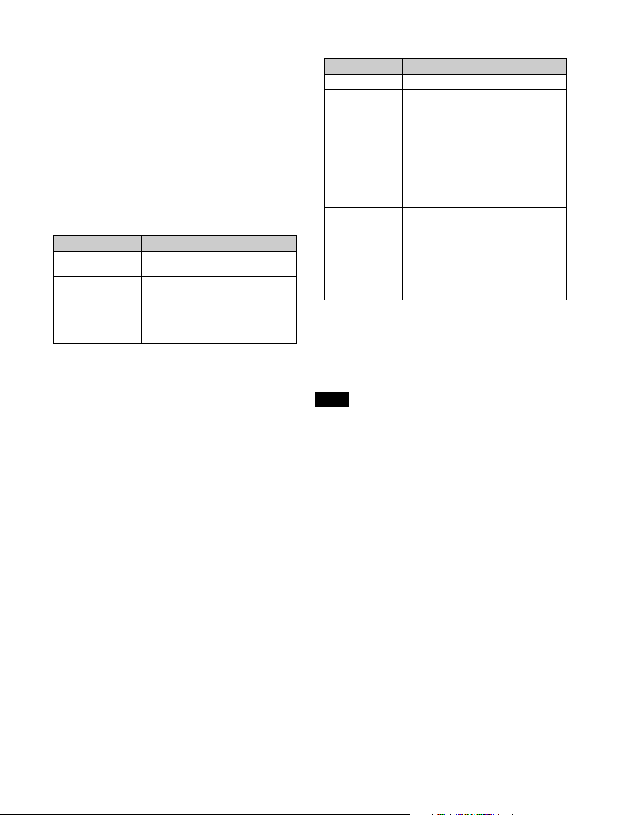
Error/Warning
本システムに発生しているエラーおよびワーニングを表示
します。
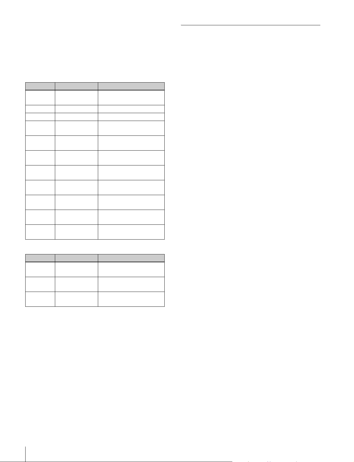
表示される主なエラーメッセージを次に示します。
ID メッセージ 説明
0101、0102 POWERSUPPLY
[A/B]ERROR
0111 〜 0115 FAN[1-5]ERROR ファンの異常を検出しました。
0121 〜 012C HDD[1-12]ERROR
0131 HIGH
TEMPERATURE
0132 HIGH
TEMPERATURE
0133 HIGH
TEMPERATURE
0134 HIGH
TEMPERATURE
0141 LOWBATTERY バックアップ電池の電圧が低下
0151 DIO-98INITIAL
ERROR
0152 SMBUSERROR MB-1204 基板の SMBUSI/F に
0153 EEPROMERROR MB-1024 基板の EEPROMI/F
電源ユニットで電源エラーを検
出しました。
HDD のエラーを検出しました。
本機内部(CPU)の温度が上昇
しました。
本機内部(MB 基板)の温度が
上昇しました。
本機内部(ストレージ)の温度
が上昇しました。
本機内部(MSQ-S321)の温度
が上昇しました。
しました。
DIO-98 基板の初期化に失敗しま
した。
エラーが発生しました。
にエラーが発生しました。
a)
表示される主なワーニングメッセージを次に示します。
ID メッセージ 説明
0201、0202 POWERSUPPLY
[A/B]WARNING
0211 〜 0215 FAN[1-5]
WARNING
0221 〜 022C HDD[1-12]
WARNING
a) 本機に HDD が装着されている場合のみ
電源ファンの回転数が低下して
います。
ファンの回転数が低下していま
す。
HDD の読み書きエラーが増加
しています。
a)
LogCollection
本システムの設定を変更します。
MenuSettings
001LINELED
前面パネルのライン LED を点灯させるかどうかを設定しま
す。
• ON:点灯する。(デフォルト)
• OFF:消灯する。
a)
002REDUNDANTPSU
別売の電源ユニットを装着して電源を二重化するかどうか
を設定します。
• ON:装着する。
• OFF:装着しない。(デフォルト)
[Save]ボタンをクリックすると、設定した内容が確定され
ます。
SNMPSettings
SNMP の設定を行います。
• CommunityName:SNMP のコミュニティ名を設定しま
す(最大 16 文字)。工場出荷時の設定値は、「public」で
す。
• HostIPAddress:SNMP ホストの IP アドレスを設定しま
す。工場出荷時の設定値は、「127.0.0.1」です。
• TrapIPAddress:Trap 送信先の IP アドレスを設定しま
す。
• SYSCONTACT:本システムの管理責任者の連絡先を入
力します(最大 255 文字)。
• SYSNAME:本システムの管理用の名前を入力します
(最大 255 文字)。
• SYSLOCATION:本システムの設置場所を入力します
(最大 255 文字)。
[Save]ボタンをクリックすると、設定した内容が確定され
ます。
[Output]ボタンをクリックすると、PWS-100 のログファ
イル(PWS-100 のメンテナンス Web アプリケーションの
ログとディスク情報)が下記のフォルダーに保存されます。
C:¥Users¥Default¥AppData¥Local¥Sony¥
PWS-100¥logs¥[OutputDirectory]
画面の説明
4
Disk ページ
本システムに HDD が装着されている場合に、HDD の状態
を表示します。
DiskStatus
HDD ごとに次の内容が表示されます。
• 物理ドライブ番号、容量
• RAID 構成時の論理ドライブ番号
• RAID の種類
• 通電時間
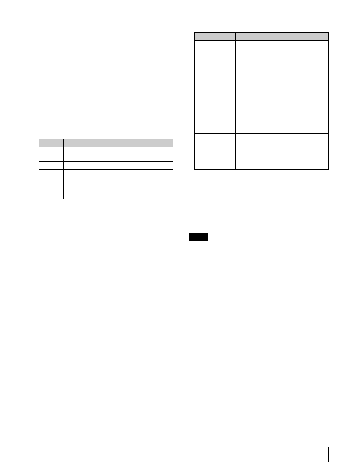
• ディスクのステータス
ディスクのステータスはドライブ番号の背景色で表され
ます。
背景色 状態
緑 正常。RAID のリビルドの進捗状況がバーで表示され
る。
赤 ワーニングが発生している。
灰 エラーが発生している。または、HDD がスピンダウ
ンされた。
HDD を取り外すことができます。
黒 HDD が挿入されていない。
[SpinDown]ボタン
選択した HDD をスピンダウンし、取り外し可能な状態に
します。
Information
選択した HDD のメーカー名とシリアル番号を表示します。
Properties
各ドライブの RAID レベル、ディスク構成、空き容量、全
容量が表示されます。
RAIDStructure
• Status:下記のいずれか
表示 状態と対応
NORMAL 正常に使用可能な状態です。
REBUILDING HDD のリビルドを行っています。通常どおり
に使用は可能です。
シャットダウンもできます。再度電源が入る
とリビルドを再開します。
リビルドの進行状況は[DiskStatus]に表示
されます。
リビルド中は、HDD をスロットから抜かない
でください。HDD 内のデータが壊れる可能性
があります。
UNFORMATTED NTFS フォーマットが必要な状態です。
[Format]ボタンをクリックしてフォーマッ
トをしてください。
NOTREADY RAID の構成に必要な HDD が揃っていない
状態です。RAID 構成に必要な HDD がス
ロットに入っているか確認してください。
本体のスロットナンバーと HDD のスロット
ナンバーが揃っているか確認してください。
[Format]ボタン
RAID 構成を変更して PWS-100 を再起動した後、選択され
た RAID 構成に従って HDD をフォーマットするときにク
リックします。
RAID 構成の変更方法
ご注意
• RAID 構成を変更すると HDD 内にあるすべてのデータが消去さ
れます。
• 装着する HDD の台数やスロットの位置は RAID 構成に合わせて
ください。
• RAID 構成の変更中は、フォーマットが終わるまで HDD の挿抜、
交換は行わないでください。
• PWS-100TD1、PWS-100MG1 などのパッケージ商品は、RAID 構
成があらかじめ決まっています。RAID 構成の情報についてはソ
ニーの営業窓口にお問い合わせください。
RAID の再構成や HDD のフォーマットができます。
搭載されている HDD の数に応じて、2D+1P、5D+1P、
11D+1P の 3 種類の RAID 構成を選択できます。
RAIDStructure ボタン
RAID 構成(2D+1P、5D+1P、11D+1P)を選択します。
ステータス画面
次の内容が表示されます。
• Drive:論理ドライブ番号
• Level:RAID 構成の種類
• Disk:HDD の割り当て状況
• UsedSpace:HDD 使用量
• FreeSpace:HDD 空き容量
• Capacity:HDD 容量
1
RAIDStructure で新しい構成を選択してから[Save]
ボタンをクリックする。
構成の変更を確認するメッセージ画面が表示されます。
2
[Yes]をクリックする。
自動的にシャットダウンすることを知らせるメッセー
ジが表示されます。
3
[OK]をクリックする。
RAID 構成が変更され、PWS-100 が自動的にシャット
ダウンします。
4
PowerON ボタンを押して PWS-100 を起動する。
画面の説明
5

5
再度 Disk 画面を開く。
6
ドライブ一覧に表示されているドライブをクリックし
てから[Format]ボタンをクリックする。
ドライブがフォーマットされ、OS で認識されるように
なります。
6
画面の説明
English
Table of Contents
Overview ............................................................................... 8
Screen Display...................................................................... 8
Diagnosis Page ........................................................................ 8
Settings Page ........................................................................... 9
Disk Page............................................................................... 10
GBGB
Table of Contents
7

Overview
Screen Display
The PWS-100 Maintenance Web Application is a system
management application for configuring settings and
displaying information for the PWS-100 via a web
browser. It allows you to perform operations, such as
viewing the current status of the PWS-100, configuring
system settings, and configuring the RAID of the installed
HDD.
Note
This document is intended for system administrators. The operations
described in this document should only be performed by a system
administrator.
To open the Maintenance Web Application, log into the
PWS-100 unit, start your web browser, and enter the
following in the address bar.
http://127.0.0.1/pws-100/maintenance/
The Maintenance Web Application consists of the
following pages.
• Diagnosis page
• Settings page
• Disk page
When you click the “?” mark at the bottom left of the
screen, a pop-up screen displaying version information for
the Maintenance Web Application will appear.
When you click the [License Information] button,
information regarding Maintenance Web Application user
licenses will appear.
Diagnosis Page
This page displays the system version, serial ID, and any
errors and warnings that occur.
Serial Number
Displays the system serial ID.
Operation Hours
Displays the cumulative running time of the system.
Version
Displays the version number of the system components.
• MB_CPLD: CPLD version of the MB board
• RAID_PKG: Package version of the RAID block
• RAID_SYS: RAID CPU version of the MB board
• RAID_FPGA: RAID FPGA version of the MB board
• RAID_CPLD: RAID CPLD version of the MB board
• HKP: Version of the maintenance application
Temperature
Displays the temperature of system components.
• CPU Core: Temperature of the CPU core
• MB-1204: Value of the temperature sensor on the
MB-1204 board
• IF-1257: Value of the temperature sensor on the IF-1257
board
• IF-1258: Value of the temperature sensor on the IF-1258
board
• IF-1259: Value of the temperature sensor on the IF-1259
board
8
Overview / Screen Display
• RAID FPGA: Internal temperature of the FPGA on the
MB-1204 board
Error/Warning
Displays errors and warnings that occur in the system.
Settings Page
This page is used to change system settings.
Menu Settings
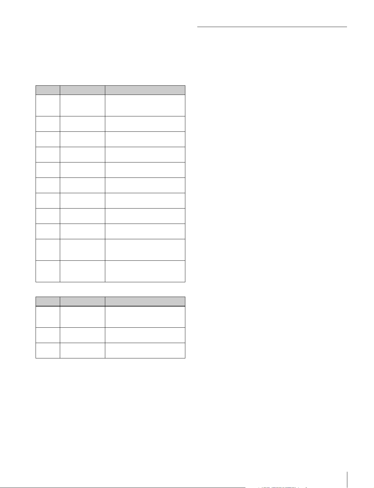
The following major error messages are displayed.
ID Message Description
0101,
0102
0111 to
0115
0121 to
012C
0131 HIGH
0132 HIGH
0133 HIGH
0134 HIGH
0141 LOW BATTERY The backup battery voltage is
0151 DIO-98 INITIAL
0152 SMBUS ERROR An error occurred on the
0153 EEPROM
POWER
SUPPLY [A/B]
ERROR
FAN [1-5]
ERROR
HDD [1-12]
ERROR
TEMPERATURE
TEMPERATURE
TEMPERATURE
TEMPERATURE
ERROR
ERROR
A power supply error was
detected in the power supply
unit.
A fan failure was detected.
An HDD error was detected.
The temperature inside the unit
(CPU) is high.
The temperature inside the unit
(MB board) is high.
The temperature inside the unit
(storage) is high.
The temperature inside the unit
(MSQ-S321) is high.
low.
Initialization of the DIO-98
board failed.
SMBUS I/F of the MB-1204
board.
An error occurred on the
EEPROM I/F of the MB-1204
board.
a)
The following major warning messages are displayed.
ID Message Description
0201,
0202
0211 to
0215
0221 to
022C
POWER
SUPPLY [A/B]
WARNING
FAN [1-5]
WARNING
HDD [1-12]
WARNING
The speed of the power supply
fan has dropped.
The speed of the fan has
dropped.
The number of HDD read/write
errors is increasing.
a)
001 LINE LED
Specifies whether the front panel LED is on/off.
• ON: LED is lit (default).
• OFF: LED is not lit.
002 REDUNDANT PSU
Specifies whether an optional power supply unit is
installed for power supply redundancy.
a)
• ON: Installed.
• OFF: Not installed (default).
Click the [Save] button to apply the settings.
SNMP Settings
Specifies SNMP settings.
• Community Name: Specifies the SNMP community
name (up to 16 characters). The default setting is
“public.”
• Host IP Address: Specifies the IP address of the SNMP
host. The default setting is “127.0.0.1.”
• Trap IP Address: Specifies the IP address of the trap
destination.
• SYS CONTACT: Specifies contact information (up to
255 characters) for the system administrator.
• SYS NAME: Specifies the system admin name (up to
255 characters).
• SYS LOCATION: Specifies the system location (up to
255 characters).
Click the [Save] button to apply the settings.
a) Only if an HDD is installed in the unit
Log Collection
When you click the [Output] button, a PWS-100 log file
(Maintenance Web Application log and disk information
for the PWS-100) will be saved to the following folder.
C:\Users\Default\AppData\Local\Sony\PWS-100\logs\
[Output Directory]
Screen Display
9
Disk Page
This page displays the status of the HDDs, if any HDDs are
installed in the system.
Disk Status
The following items are displayed for each HDD.
• Physical drive number and capacity
• Logical drive number when used in a RAID structure
•RAID type
• Power on time
• Disk status
The disk status is displayed using the drive number
background color.
Background color Status
Green Normal. A progress bar appears
during RAID rebuilding.
Red A warning has been issued.
Gray An error has occurred. Or an HDD
has spun down.
You can then remove the HDD.
Black The HDD is not inserted.
[Spin Down] button
Spins down the selected HDD so that it can be removed.
• Status: One of the following
Display Status and appropriate action
NORMAL Ready for normal operation.
REBUILDING Rebuilding of the HDD is in progress.
Normal operation is possible.
Shutdown is also possible with the
rebuilding process resuming once the
unit is turned on again.
The rebuilding progress is displayed in
[Disk Status].
Do not remove the HDD from the slot
while rebuilding is in progress. Doing
so may damage the data stored on the
HDD.
UNFORMATTED NTFS formatting is required. Click the
[Format] button to perform formatting.
NOT_READY The HDDs required for the RAID
configuration are not connected. Verify
that the HDDs required for the RAID
configuration are inserted in the slots.
Verify that the slot numbers of the unit
and the HDD slot numbers match.
[Format] button
After changing the RAID configuration and restarting the
PWS-100, click this to format the HDDs according to the
selected RAID configuration.
Changing the RAID configuration
Information
Displays the manufacturer and serial number of the
selected HDD.
Properties
Displays the RAID level of each drive, disk configuration,
free space, and total capacity.
RAID Structure
Allows you to reconfigure the RAID or format the HDD.
Depending on the number of HDDs installed, you can
select from three RAID configurations; 2D+1P, 5D+1P, or
11D+1P.
RAID structure button
Select the RAID configuration (2D+1P, 5D+1P, 11D+1P).
Status screen
Displays the following.
• Drive: Logical drive number
• Level: RAID configuration type
• Disk: HDD allocation status
• Used Space: HDD used capacity
• Free Space: HDD remaining capacity
• Capacity: HDD total capacity
Notes
• Changing the RAID configuration will delete all data stored on the HDDs.
• Determine the number of HDDs to install and the slot positions based on
the RAID configuration.
• When changing the RAID configuration, do not insert, remove, or swap
HDDs until formatting is complete.
• Packaged products, such as the PWS-100TD1 and PWS-100MG1, come
with the RAID configuration already configured. For details on the RAID
configurations, contact your local Sony representative.
1
Select the new RAID configuration in [RAID
Structure], and then click [Save].
A message to confirm the changing of the
configuration appears.
2
Click [Yes].
A message indicating that the unit will automatically
shut down appears.
3
Click [OK].
The RAID configuration is changed, and the PWS-100
automatically shuts down.
4
Press the on/standby button to start the PWS-100.
10
Screen Display
5
Open the [Disk] page again.

6
Click the drive that appears in the drive list, and then
click the [Format] button.
The drive is formatted and will be recognized by the
OS.
Screen Display
11

Français
Table des matières
Présentation........................................................................ 13
Affichage de l’écran ........................................................... 13
Page de Diagnosis ................................................................. 13
Page de Settings .................................................................... 14
Page de Disk.......................................................................... 15
12
Table des matières

Présentation
Affichage de l’écran
L’application Maintenance Web PWS-100 est une
application de gestion de système pour la configuration de
réglages et l’affichage d’informations de la PWS-100 par
le biais d’un navigateur Web. Elle vous permet d’effectuer
des opérations telles que la visualisation de l’état actuel de
la PWS-100, la configuration des réglages du système et la
configuration RAID du disque dur installé.
Remarque
Ce document e st destiné aux administ rateurs système. Les opérat ions décrites
dans ce document ne doivent être effectuées que par un administrateur
système.
Pour ouvrir l’application Maintenance Web, connectezvous à l’unité PWS-100, lancez votre navigateur Web et
saisissez le lien suivant dans la barre d’adresse.
http://127.0.0.1/pws-100/maintenance/
L’application Maintenance Web comprend les pages
suivantes.
• Page de Diagnosis
• Page de Settings
• Page de Disk
Lorsque vous cliquez sur le signe « ? » en bas à gauche de
l’écran, un écran contextuel qui affiche les informations de
version pour l’application Maintenance Web apparaîtra.
Lorsque vous cliquez sur le bouton [License Information],
les informations concernant les licences utilisateur de
l’application Maintenance Web apparaîtront.
Page de Diagnosis
Cette page affiche les informations de système,
l’identifiant de série et toutes les erreurs et les
avertissements qui se produisent.
GBFR
Serial Number
Affiche l’identifiant de série du système.
Operation Hours
Affiche la durée d’exécution cumulative du système.
Version
Affiche le numéro de version des composants du système.
• MB_CPLD : version CPLD de la carte MB
• RAID_PKG : version progicielle du bloc RAID
• RAID_SYS : version CPU RAID de la carte MB
• RAID_FPGA : version FPGA RAID de la carte MB
• RAID_CPLD : version CPLD RAID de la carte MB
• HKP : version de l’application de maintenance
Temperature
Affiche la température des composants du système.
• CPU Core : température de l’unité CPU
• MB-1204 : valeur du capteur de température sur la carte
MB-1204
• IF-1257 : valeur du capteur de température sur la carte
IF-1257
• IF-1258 : valeur du capteur de température sur la carte
IF-1258
Présentation / Affichage de l’écran
13
 Loading...