

Sony PLM-S700E Service Manual
PLM-S700E
SERVICE MANUAL
SPECIFICATIONS
AEP Model
9-928-115-31
– Continued on next page –
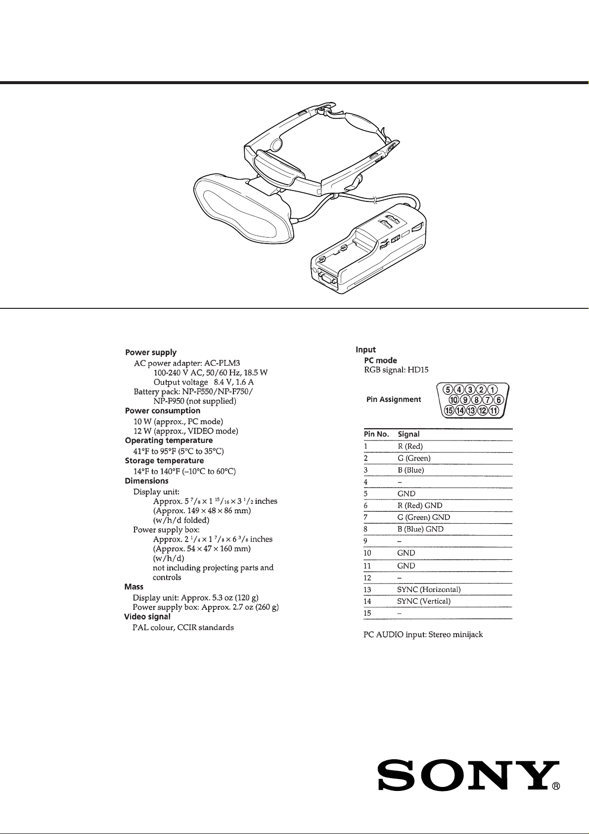
GLASSTRON
Notes on chip component replacement
• Never reuse a disconnected chip component.
• Notice that the minus side of a tantalum capacitor may be damaged by heat.
Flexible Circuit Board Repairing
• Keep the temperature of the soldering iron around 270 ˚C during repairing.
• Do not touch the soldering iron on the same conductor of the
circuit board (within 3 times).
• Be careful not to apply force on the conductor when soldering
or unsoldering.
TABLE OF CONTENTS
1. GENERAL
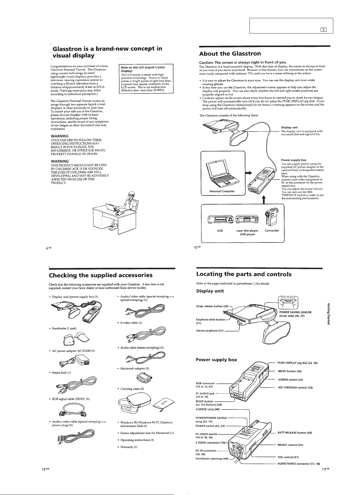
Glasstron is a brand-new concept in visual display .... 1-1
About the Glasstron ..................................................... 1-1
Checking the supplied accessories .............................. 1-1
Locating the parts and controls ................................... 1-1
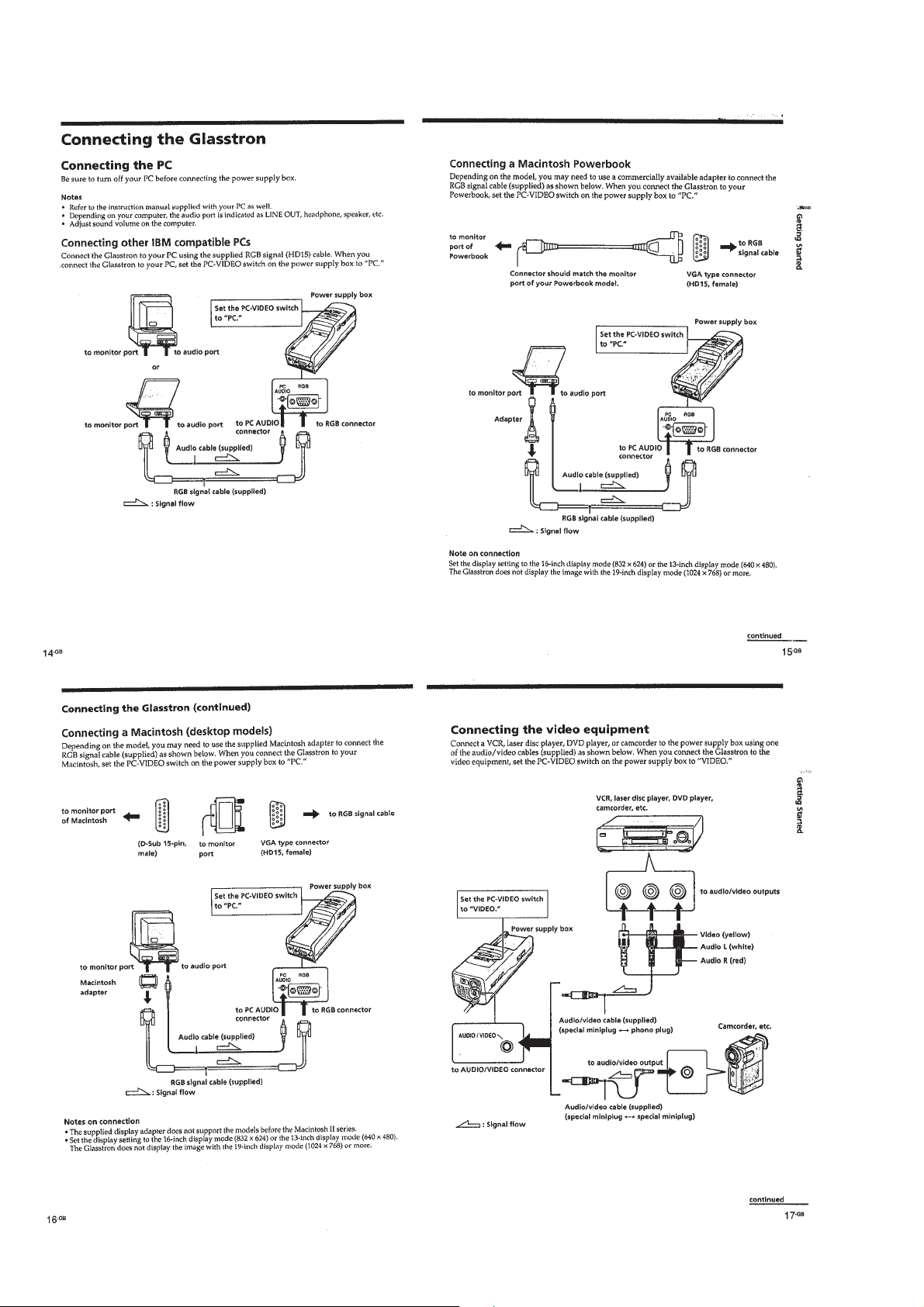
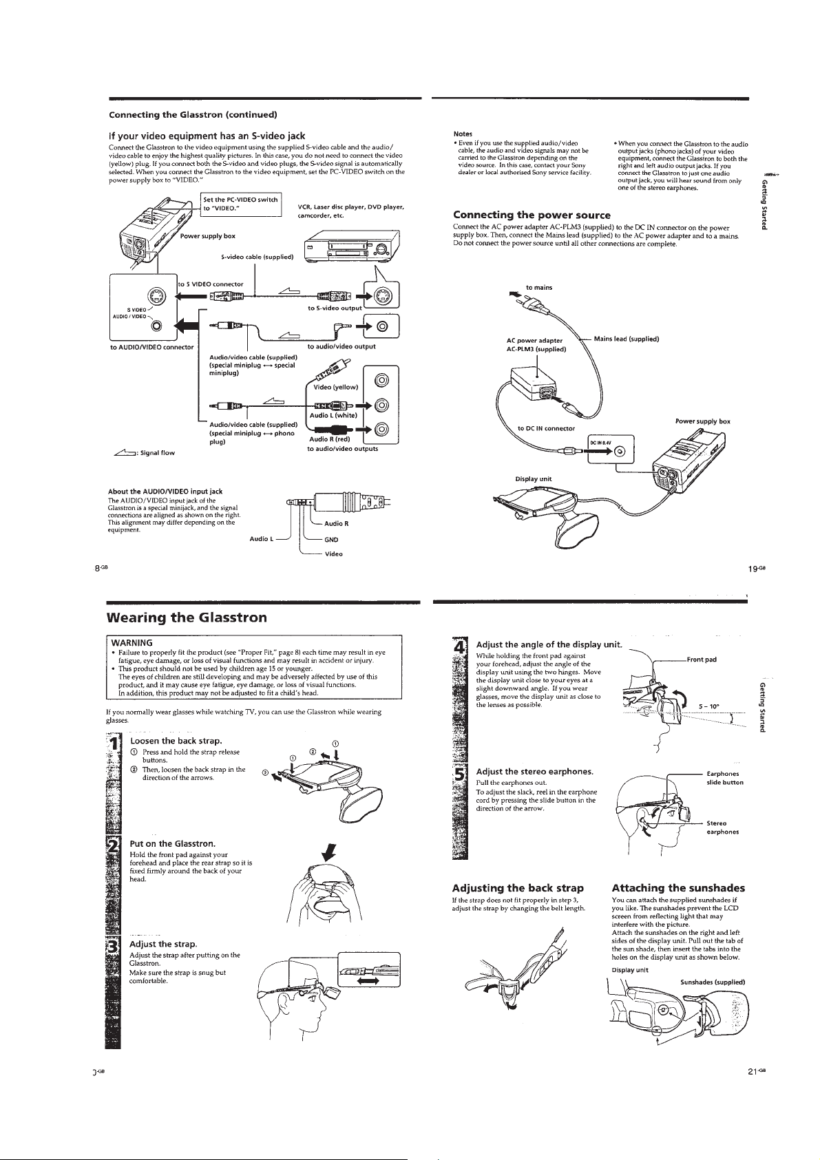
Connecting the Glasstron............................................. 1-2
Wearing the Glasstron .................................................. 1-3
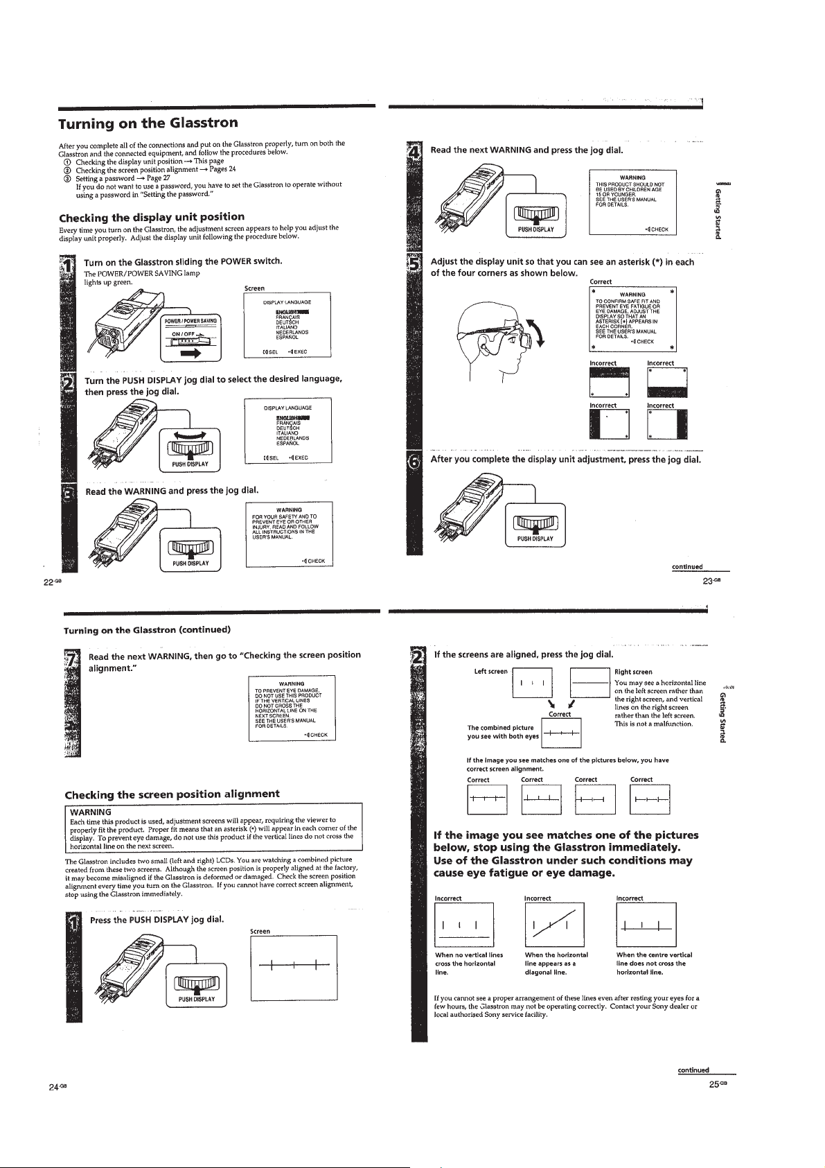
Turning on the Glasstron ............................................. 1-4
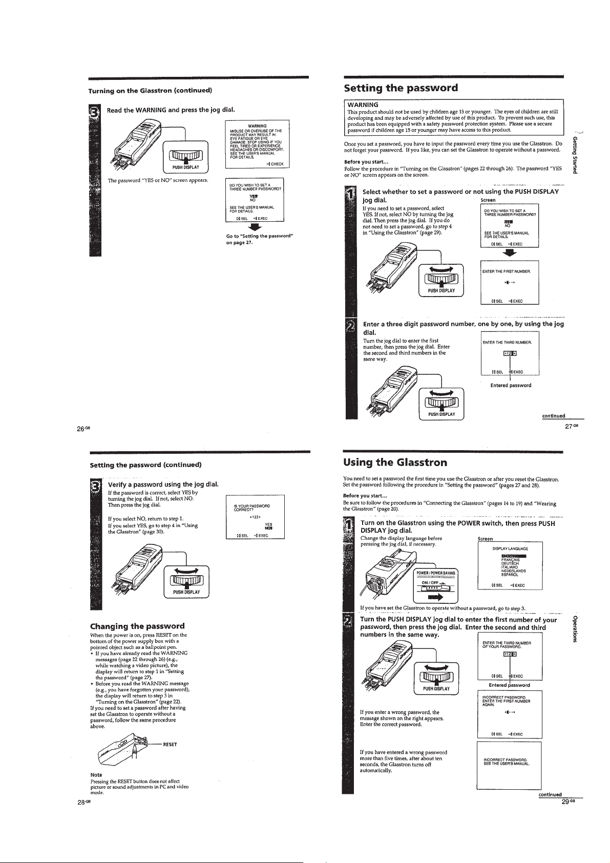
Setting the password .................................................... 1-5
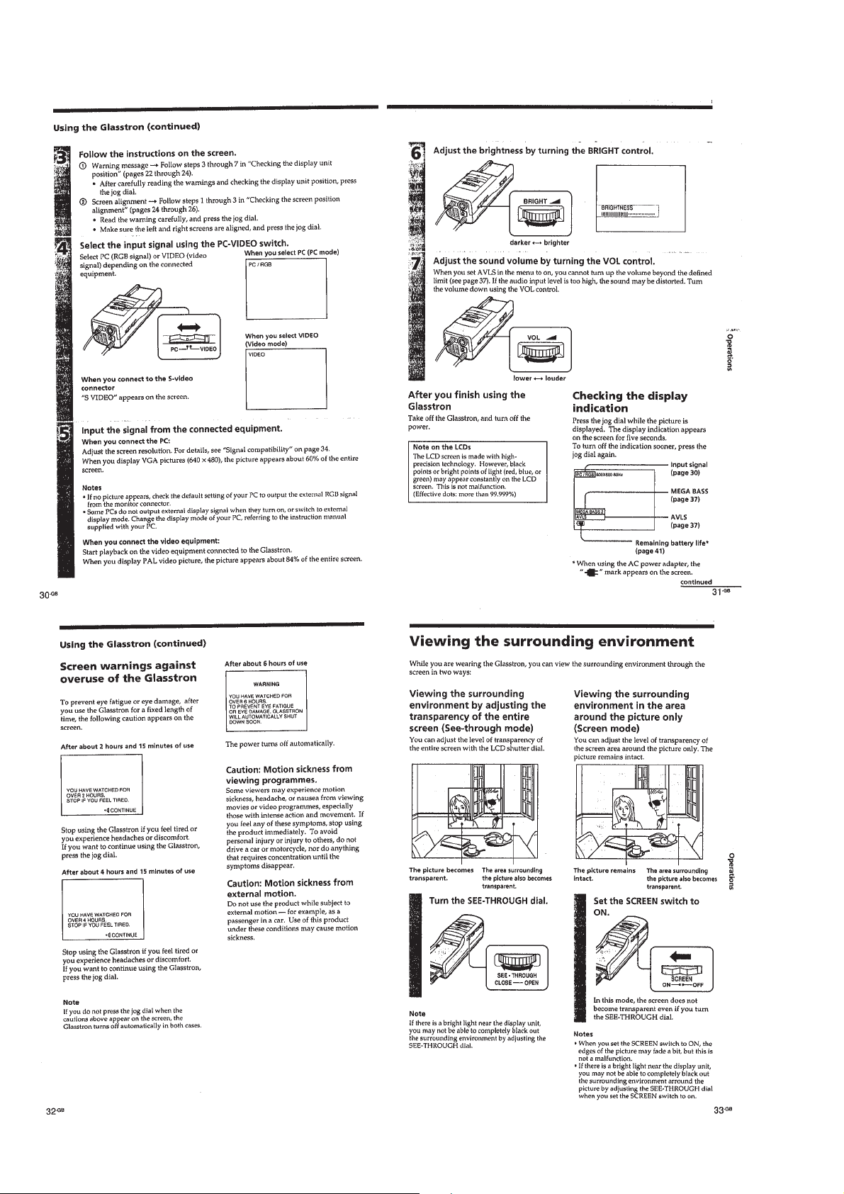
Using the Glasstron...................................................... 1-5
Viewing the surrounding environment ........................ 1-6
Adjusting the sound and picture .................................. 1-7
Using the optional battery pack................................... 1-8
2. DISASSEMBLY ...................................................... 2-1
3. ELECTRICAL ADJUSTMENTS...................... 3-1
4. DIAGRAMS
4-1. Block Diagram – AUDIO/VIDEO Section – ............. 4-1
4-2. Block Diagram
– A/D, D/A, OSD, SYNC Section –............................ 4-5
4-3. Block Diagram
– GAMMA CONTROL/LCD DRIVE Section – ........ 4-7
4-4. Block Diagram
– MODE CONTROL/SENSOR/LCS Section – ......... 4-9
4-5. Block Diagram – POWER SUPPLY Section –.......... 4-11
4-6. Notes for Printed Wiring Board and
Schematic Diagram...................................................... 4-14
4-7. Printed Wiring Board – JK-136 Board –.................... 4-15
4-8. Schematic Diagram – JK-136 Board –........................ 4-16
4-9. Schematic Diagram – YC-148 Board (1/3) – .............. 4-17
4-10. Schematic Diagram – YC-148 Board (2/3) –.............. 4-19
4-11. Schematic Diagram – YC-148 Board (3/3) –.............. 4-24
4-12. Printed Wiring Board – YC-148 Board – ................... 4-27
4-13. Printed Wiring Board – MA-324 Board –.................. 4-31
4-14. Schematic Diagram – MA-324 Board (1/7) –............. 4-35
4-15. Schematic Diagram – MA-324 Board (2/7) –............. 4-39
4-16. Schematic Diagram – MA-324 Board (3/7) –............. 4-43
4-17. Schematic Diagram – MA-324 Board (4/7) –............. 4-46
4-18. Schematic Diagram – MA-324 Board (5/7) –............. 4-49
4-19. Schematic Diagram – MA-324 Board (6/7) –............. 4-53
4-20. Schematic Diagram – MA-324 Board (7/7) –............. 4-55
4-21. Printed Wiring Board – LC-61 Board – ..................... 4-57
4-22. Schematic Diagram – LC-61 Board – ......................... 4-59
4-23. Printed Wiring Board – SW-306 Board –................... 4-62
4-24. Schematic Diagram – SW-306 Board – ...................... 4-65
4-25. Printed Wiring Board – DD-107 Board –................... 4-67
4-26. Schematic Diagram – DD-107 Board – ...................... 4-69
4-27. IC Pin Function Description ........................................ 4-88
5. EXPLODED VIEWS............................................. 5-1
6. ELECTRICAL PARTS LIST ............................ 6-1
SAFETY-RELATED COMPONENT WARNING!!
COMPONENTS IDENTIFIED BY MARK ! OR DOTTED
LINE WITH MARK ! ON THE SCHEMATIC DIAGRAMS
AND IN THE PARTS LIST ARE CRITICAL TO SAFE
OPERATION. REPLACE THESE COMPONENTS WITH
SONY PARTS WHOSE PART NUMBERS APPEAR AS
SHOWN IN THIS MANU AL OR IN SUPPLEMENTS PUBLISHED BY SONY.
– 2 –
SECTION 1
GENERAL
This section is extracted from instruction manual (3-862-932- ).
1-1
1-2
1-3
1-4
1-5
1-6
1-7
1-8
1-8 E
SECTION 2
DISASSEMBLY
Note: Follow the disassembly procedure in the numerical order given.
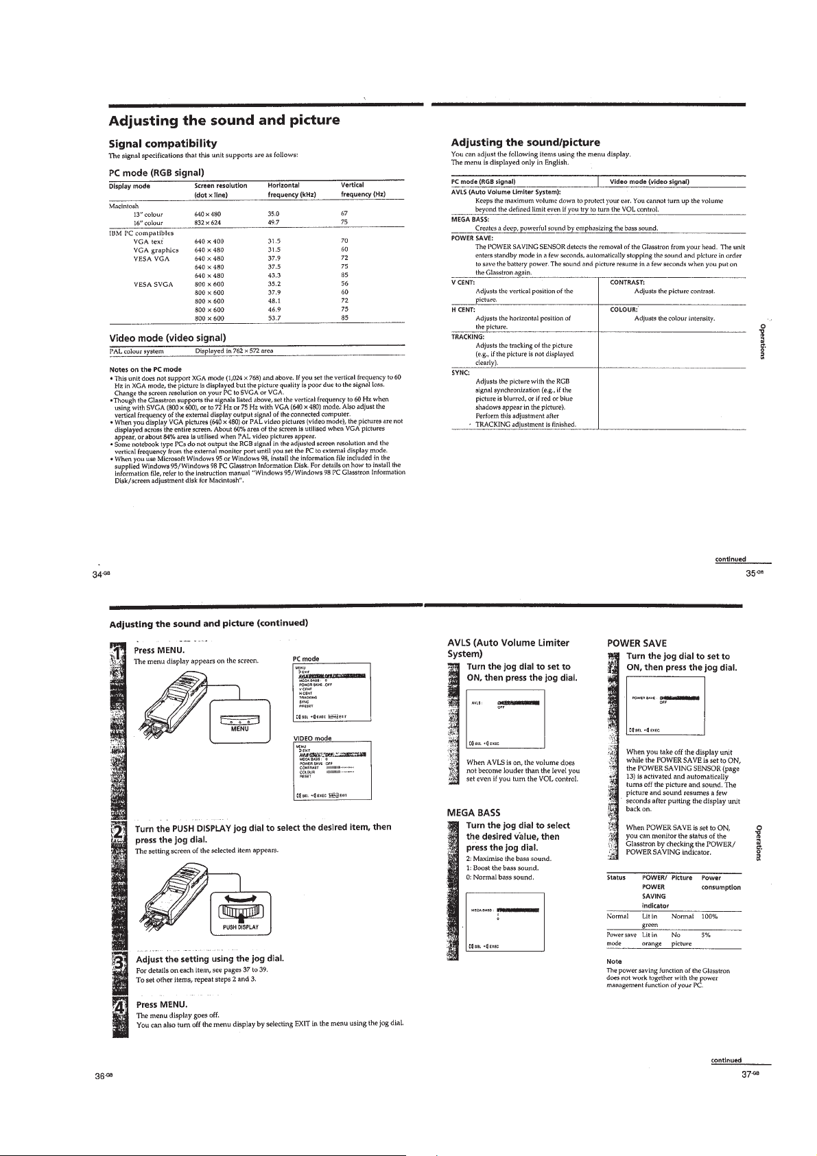
LOADING BLOCK ASSY
1
screw
(M1.4
×
3.0)
6
FP661 flexible
board (CN803)
1
screw
(M1.4
×
3.0)
2
loading block assy
1
three screws
(M1.4
×
5
rear cabinet assy
3.0)
LC-61 BOARD
4
two claws
7
3
flexible board
(CN802)
flexible board
(CN805)
2
connector
(back light unit)
1
4
two screws
(M1.7 × 5)
3
3
screw
(M1.4
screw
(M1.4
×
3.0)
flexible board
(CN801)
6
4
two claws
×
3.0)
LC-61 board
2-1
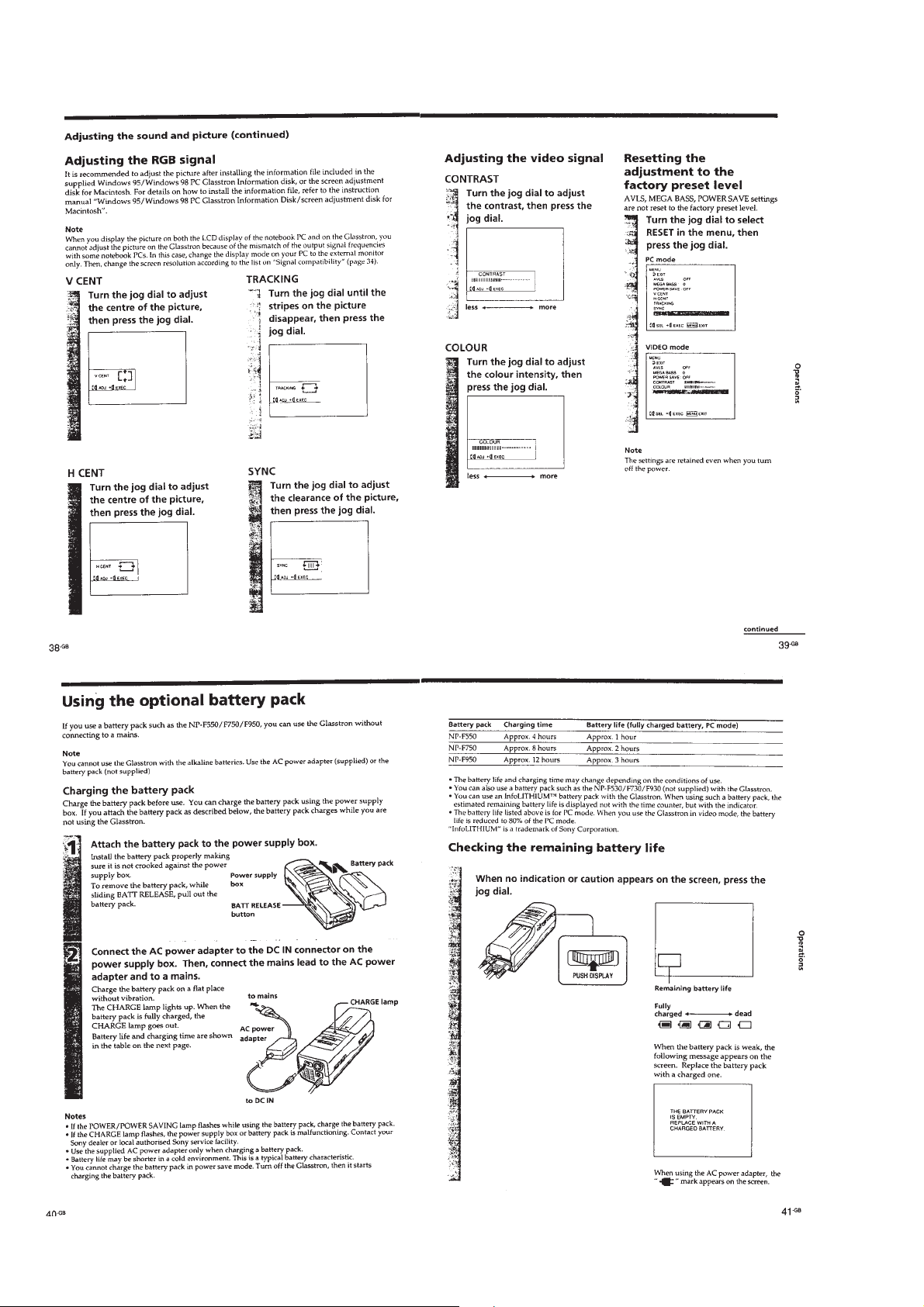
1
front panel
5
connection cable
7
flexible board
(CN804)
BACK LIGHT UNIT
1
screw
(M1.7 × 5)
3
back light unit
2
claw
OPTICS BLOCK ASSY, FILM (PANEL) LIQUID CRYSTAL
3
optics block assy
4
shutter holder (C)
1
screw
(P1.7 × 4.0)
2
lens fixed plate
5
two film (panel) liquid crystals (C)
2-2 E
2-2
SECTION 3
White (100%)
approx.
0.3 V
approx.
0.7 V
approx.
0.3 V
• When color bar signals are entered
Red
Burst signal (flat)
Horizontal sync signal
ELECTRICAL ADJUSTMENTS
Precautions on adjustment:
1. Perform the adjustment in the given order.
2. Power supply voltage: DC 8.4 V
3. Equipment required
Electrical adjustment requires the following measuring equipment.
(1) Oscilloscope: 2 phenomena, band 30 MHz or more, with de-
lay mode (use 10 : 1 probe unless otherwise specified)
(2) Pattern generator
(3) Regulated power supply × 2
(4) Digital voltmeter
(5) Frequency counter
(6) Connector for adjustment
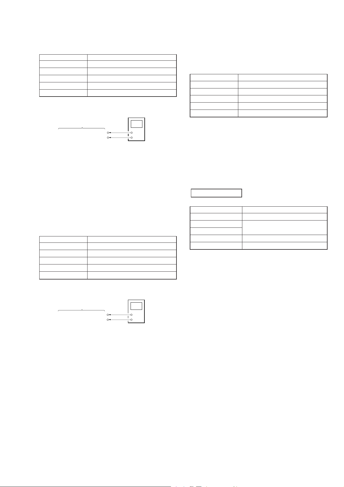
4. Measurement points for adjustment are located at CN1003 on
the YC-148 board and at CN206 on the MA-324 board. The
pin No. and signal name of CN1003 and CN206 are listed below.
• YC-148 Board, CN1003
Pin No. Signal Name
1 GND
2 GND
3 GND
4 4FSC
5 GND
Pin No. Signal Name
6 GND
7 Y OUT
8 VIDEO G
9 N.C
10 GND
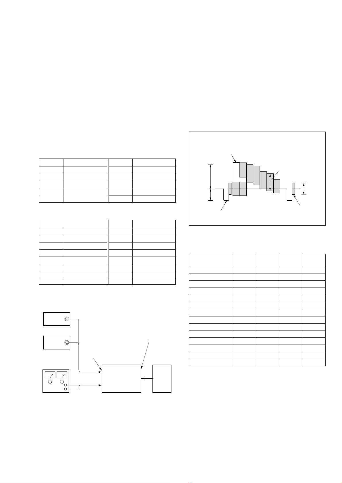
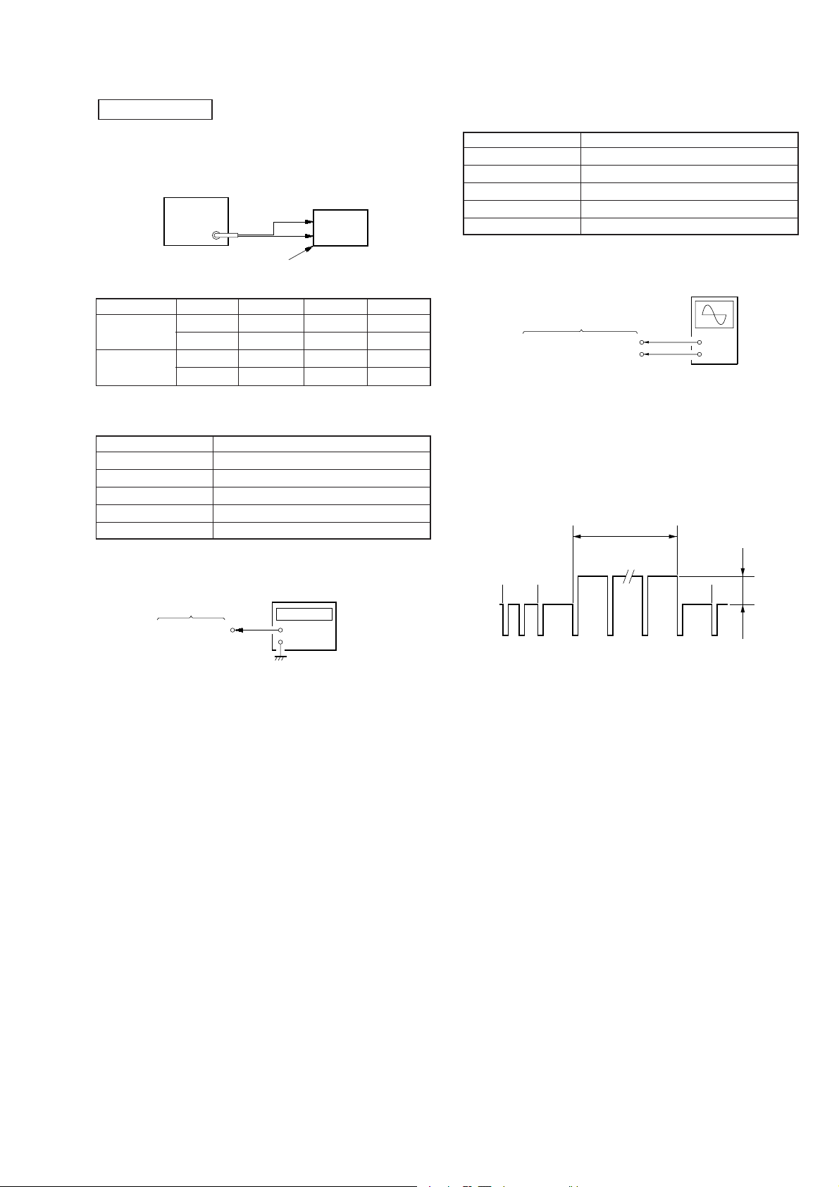
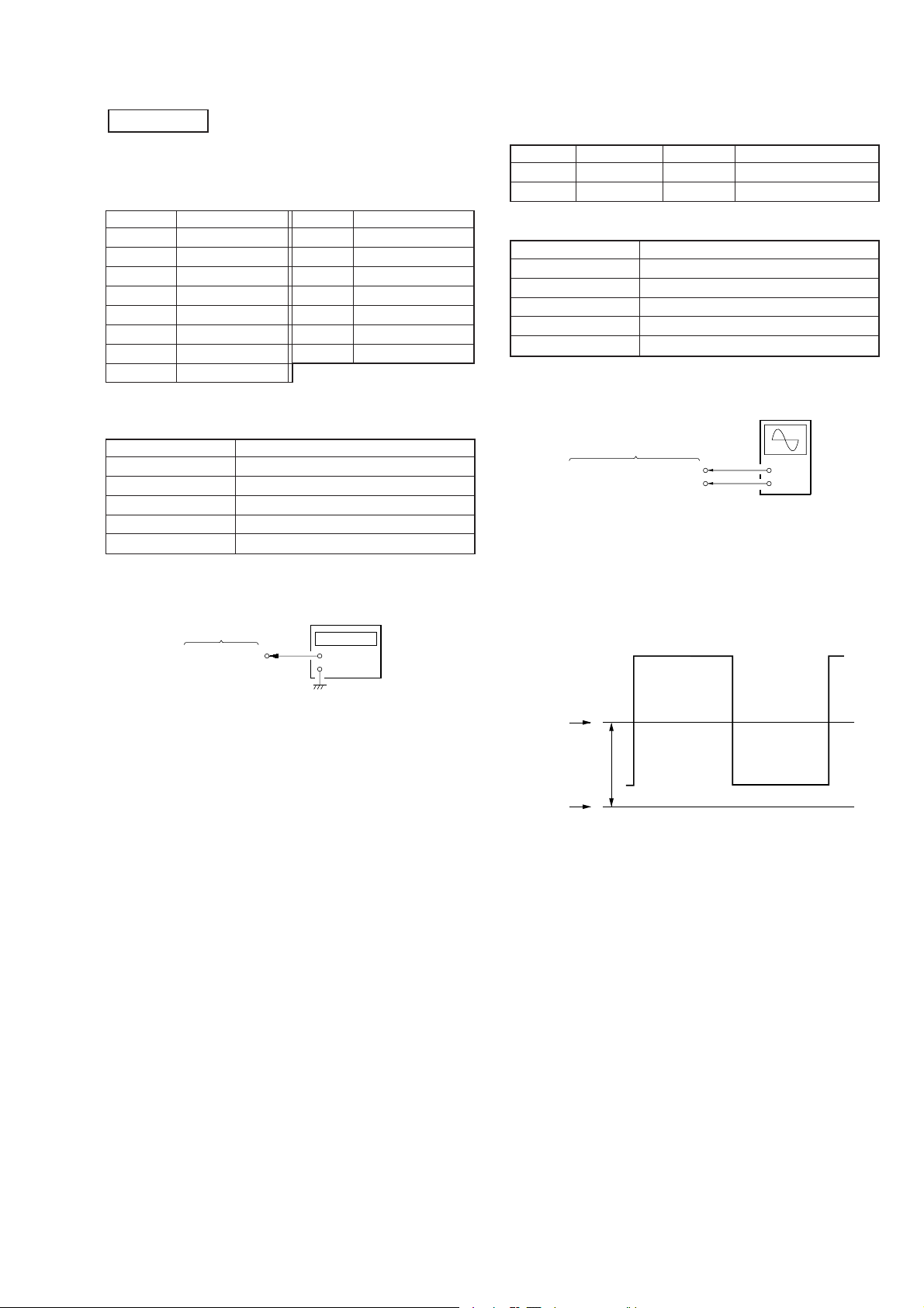
5. Setting up Input Signals
(1) Video Signal
In adjusting this set, video signals obtained from the pattern
generator are used, and therefore these video output signals
must satisfy the specification. Connect the oscilloscope to the
VIDEO IN terminal, and confirm that the sync signal amplitude of video signals is approximately 0.3 V, the amplitude of
video part is approximately 0.7 V, burst signal amplitude is
approximately 0.3 V and flat, and the level ratio of burst signal to “red” signal is 0.30 : 0.66.
Where “chroma signal, and color bar signal with burst signal
turned off” is specified in the text, enter chroma signal and
color bar signal of which burst signal is turned off to the VIDEO
IN terminal as video input signals for adjustment.
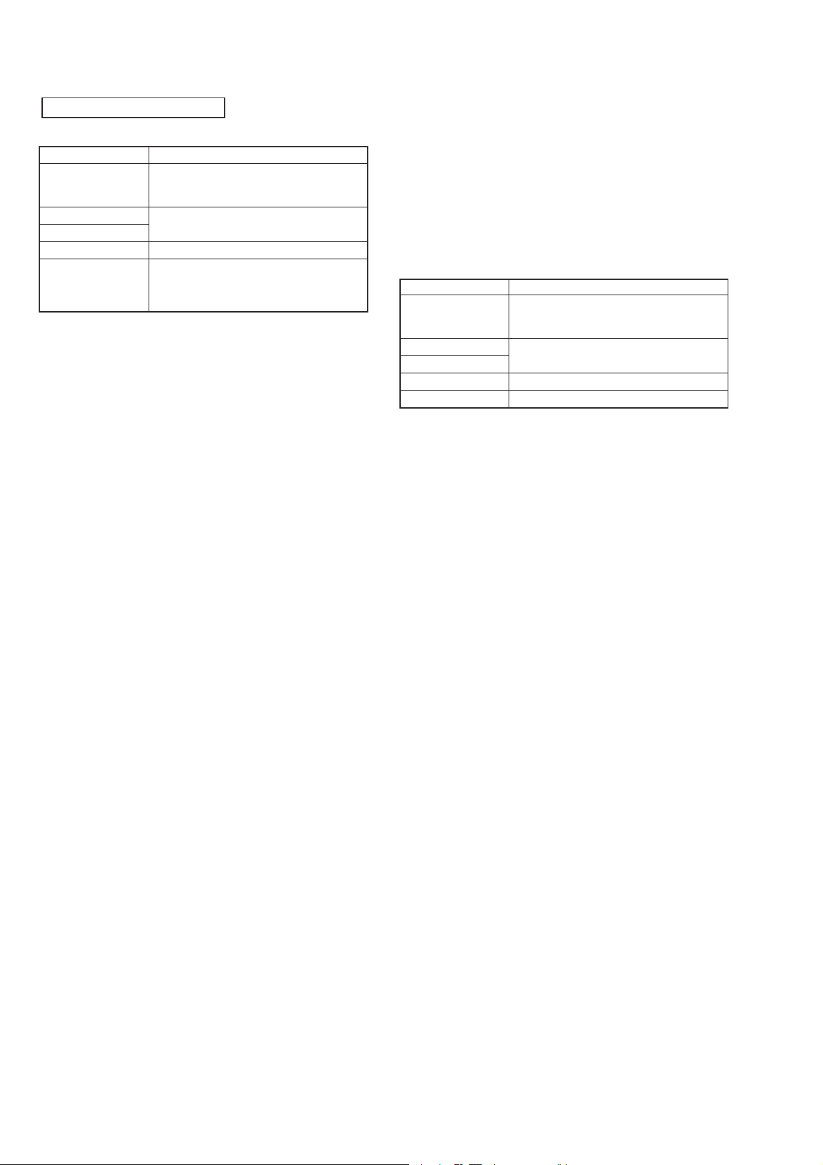
• MA-324 Board, CN206
Pin No. Signal Name
1 SIG R 1
2A
3 SIG G 1
4 POWER SW
5 SIG B 1
6 ENTER
7 INT H
8 VIDEO/XPC IN
Pin No. Signal Name
9 GND
10 GND
11 B
12 COM R
13 C
14 COM L
15 SIG CEN
16 P SIG B
Preparation:
Connect electrical blocks as shown below.
VIDEO
SG
AUDIO
SG
DC 8.4V
AUDIO/VIDEO terminal
YC-148 board
(J1002)
DD-107 board
(J701)
suitable
Set PC
RGB terminal
MA-324 board
(J101)
Fig. 3-1. Pattern generator's color bar signals
(2) PC Signal (RGB signal)
Signal mode
PC98 24.82 56.41 640 400
VGA-TEXT 31.47 70.08 640 362
VGA-GRAP 31.47 59.94 640 480
VGA72 37.86 72.82 640 480
VGA75 37.50 74.99 640 480
MAC13’ 35.00 66.67 640 480
VGA85 43.27 85.01 640 480
SVGA56 35.16 56.26 800 600
SVGA60 37.88 60.32 800 600
SVGA72 48.08 72.19 800 600
SVGA75 46.88 75.01 800 600
SVGA85 53.68 85.07 800 600
MAC16’ 49.73 74.55 832 624
XGA60 48.36 59.99 1024 768
H V HDISP VDISP
(kHz) (Hz) (dots) (dots)
3-1
[Preparation for Adjustment]
1. Service Jigs
(1) Adjusting remote commander (RM-95-modified)
Note 1: J-6082-053-B
(2) Extension cable (for remote commander plug converter)
J-6082-291-A
Note 1: The page will not be changed over, unless the microprocessor in
the adjusting remote commander is a new one (UPD7503-G-C56-
12). In such a case, replace with new microprocessor (8-759148-35).
2. Adjusting Remote Commander
For the adjustment, the adjustment data saved in the nonvolatile memory (EEPROM) must be rewritten, and for this purpose the adjusting remote commander is used.
The adjusting remote commander makes two-way communication with the product using a remote control signal line
(LANC). The adjusting remote commander transmits pages,
addresses, and data up/down commands to the product. The
product transmits pages, addresses, and data to the adjusting
remote commander.
3. How to Use Adjusting Remote Commander
(1) Connect the adjusting remote commander to the CN501 on
MA-324 board via extension cable (J-6082-291A).
At this time, set the switch of extension cable to OFF
(
(OPEN) position.
Set the [PC] or [VIDEO] mode and turn ON the power on
the set.
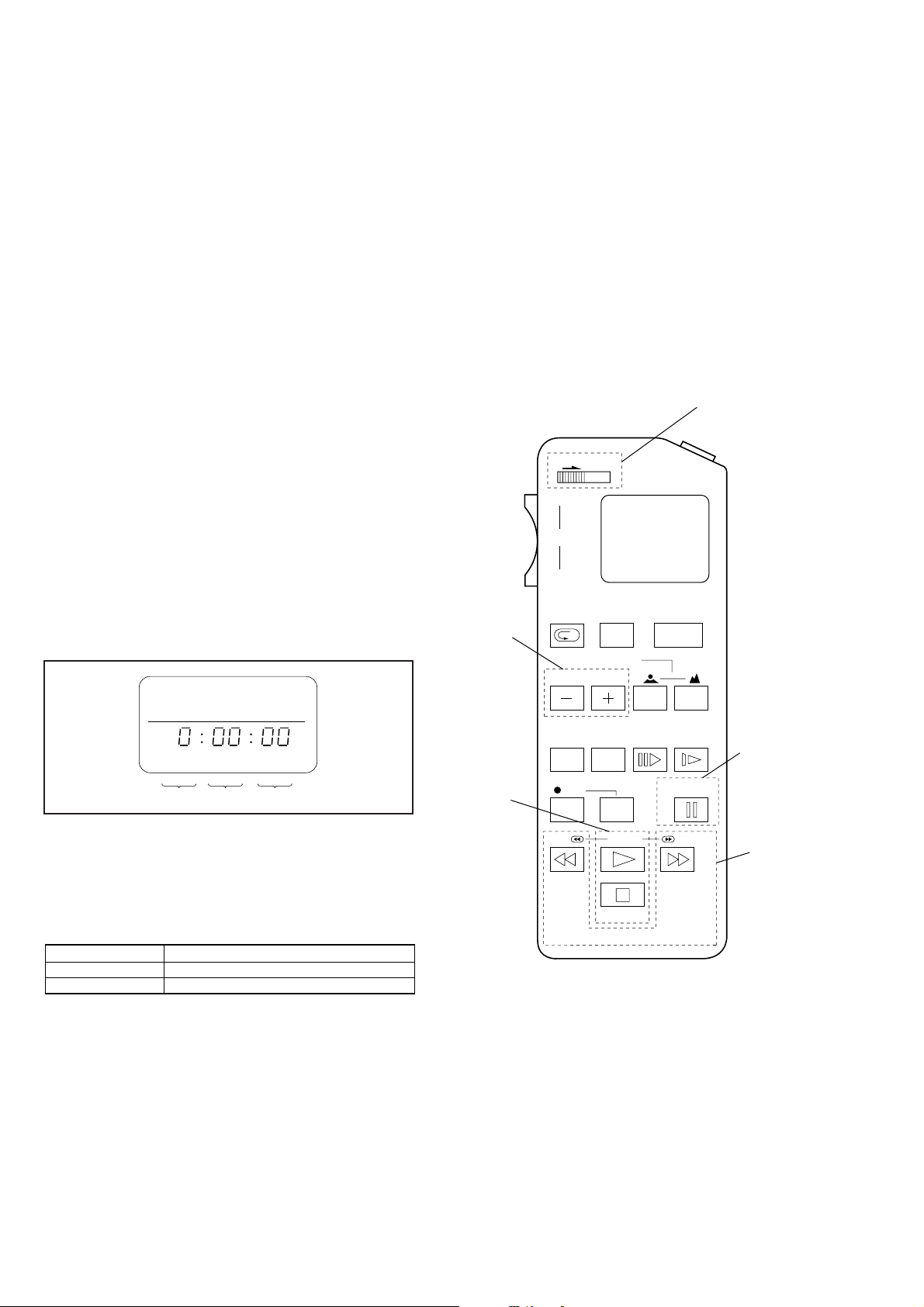
(2) Set the HOLD switch on the adjusting remote commander to
the HOLD (SERVICE) position.
If connection is normal, the LCD display on the adjusting
remote commander will be as shown in Fig.3-2.
(4) Select page: 0, address: FF, and set 01 data. Thus, the data
input to page: E or F is enabled.
(5) After the adjustment finished, select page: 0, address: FF, and
set 00 data. Thus, the data change on page E or F is disabled.
(6) After all adjustments finished, turn OFF the main power sup-
ply (8.4 V) once.
4. Precaution on Use of Adjusting Remote Commander
Misoperation of the adjusting remote commander could erase
correct data. T o prev ent this, it is recommended to make a note
of data from page E or F before adjustment, and also to make
a note of new adjustment data each time the adjustment of one
item is finished.
Adjusting Remote Commander RM-95 (J-6082-053-B)
NORMAL/SERVICE
mode selection
)
Page change
HOLD
WIDE
ZOOM
TELE
REC
REVIEW
AUTO/MAN
EDIT SEARCH
FOCUS
START/
STOP
POWER
Page Data Address
Fig. 3-2
(3) Operate the adjusting remote commander as follows:
• Page change
Press the EDIT SEARCH + button to increase the page.
Press the EDIT SEARCH – button to decrease the page.
There are 16 pages from 0 to F.
Hexadecimal numbers
LCD display
Decimal conversion
0123456789ABCDEF
23456789A b c d E F
10
2 3 4 5 6 7 8 9 10 11 12 13 14 15
10
• Address change
Press the FF ()) button to increase the address.
Press the REW (0) button to decrease the address.
There are 256 addresses from 00 to FF.
• Data change (data setting)
Press the PLAY (() button to increase the data.
Press the STOP (p) button to decrease the data.
There are 256 data from 00 to FF.
• Adjustment data writing
The PAUSE button must be pressed to write adjustment
data (E or F pages) to the nonvolatile memory (EEPR OM).
(Unless the PAUSE is pressed, new data are not saved in
the nonvolatile memory.)
Data change
COUNTER
RESET DISPLAY FRAME SLOW
PAUSE
FF
RM-95
REW
REC
PB
STOP
Fig. 3-3
Data writing
Address
change
3-2
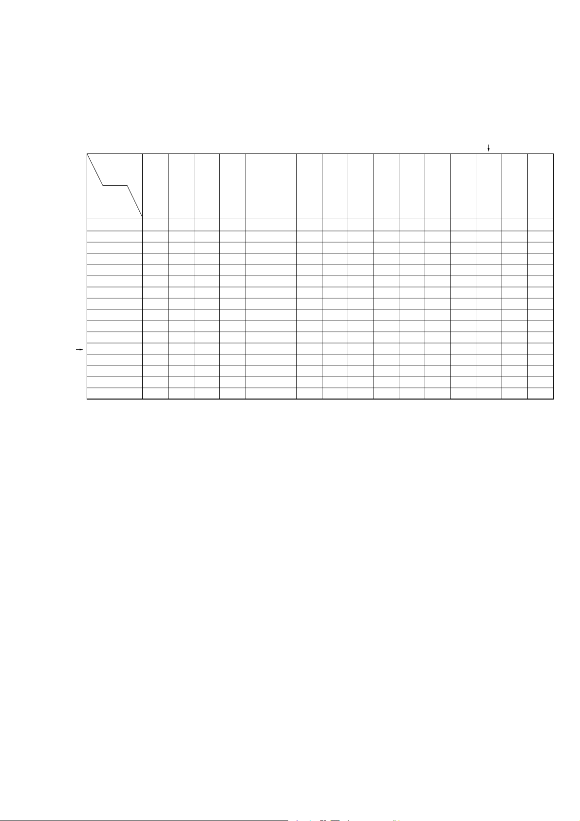
5. Data Processing
Certain adjustment items require the microprocessor data to be read out or the displayed data (hexadecimal numbers) on jigs or
adjusting remote commander to be calculated to get adjustment data. In such a case, convert hexadecimal numbers into decimal
numbers once, then make calculation, and convert its result into he xadecimal n umber as adjustment data. Table 1 shows hexadecimal
– decimal number conversion.
Hexadecimal – Decimal number conversion.
Lower digit
of hex.
0123456789
Higher digit
of hex.
00
123456789
1
1
2
3
4
5
6
7
8
9
A (A)
B (b)
C (c)
D (d)
E (E)
F (F)
16 17 18 19 20 21 22 23 24 25
32 33 34 35 36 37 38 39 40 41
48 49 50 51 52 53 54 55 56 57
64 65 66 67 68 69 70 71 72 73
80 81 82 83 84 85 86 87 88 89
96 97 98 99 100 101 102 103 104 105
112 113 114 115 116 117 118 119 120 121
128 129 130 131 132 133 134 135 136 137
144 145 146 147 148 149 150 151 152 153
160 161 162 163 164 165 166 167 168 169
176 177 178 179 180 181 182 183 184 185
192 193 194 195 196 197 198 199 200 201
208 209 210 211 212 213 214 215 216 217
224 225 226 227 228 229 230 231 232 233
240 241 242 243 244 245 246 247 248 249
Tab le 1.
2
A
(A) B(b) C(c) D(d) E(E) F(F)
10
26
42
58
74
90
106
122
138
154
170
186
202
218
234
250
11
27
43
59
75
91
107
123
139
155
171
187
203
219
235
251
12
13 14 15
28
29 30 31
44
45 46 47
60
61 62 63
76
77 78 79
92
93 94 95
108
109 110 111
124
125 126 127
140
141 142 143
156
157 158 159
172
173 174 175
188
189 190 191
204
205 206 207
220
221 222 223
236
237 238 239
252
253 254 255
Note: Data in ( ) are displayed on jig or adjusting remote commander.
Example:If display on jig or adjusting remote commander is BD (bd)
As higher digit of hex. number is B (b) and lower digit is D (d), the intersection “189” of 1 and 2 in Table 1 is the target decimal number.
3-3
6. Power ON Procedure for Adjustment
(1) Connect an extension cable to the adjusting remote commander.
(2) Set the [PC] or [VIDEO] mode on the set.
(3) After making sure that the HOLD switch on the adjusting remote commander is not turned on (not at left (NOR) position), supply 8.4
Vdc to the DC IN (J701).
(With the HOLD switch at HOLD position, the initial operation of the set does not finish, disabling the POWER switch function.)
(4) Turn ON the POWER switch on the set. Confirm that a green LED lights up.
(5) Set the HOLD switch on the adjusting remote commander to the HOLD (right (ADJ)) position.
7. Adjustment Finishing Procedure
Order Page Address Data Description Remarks
1. E or F Check if adjusted data are written correctly to the given page and address.
2. 2 FF 00
3. 0 FF 00 Page E or F: Write protect
4. Set HOLD switch on adj. remote commander to NOR position.
Set data 00 to given page and address.
Page 2: Reset
8. Password Reset (for operation check of the set)
(1) Turn the PO WER switc h on, then press the “Pass word Reset” a t the bottom of Po wer Bo x to reset the passwor d set by the customer.
(2) Operating the jog dial, select “No” on the Password Set screen to set “disuse of password”.
Or,
Order Page Address Data Description Remarks
1. 0 01 01 Set data 01 to given page and address. Page E or F: Cancel protect
2. E or F 04 FF Set data FF to given page and address and press PAUSE. Set disuse of password
Final: After all adjustments and operation check finished, turn the POWER switch on, press the "Password Reset" at the bottom of Power Box, and
turn the POWER switch off.
9. EXT. VIDEO AUDIO mode: Turn the POWER switch on, and press and operate the jog dial from the initial screen.
Or,
Order Page Address Data Description Remarks
1. 2 00 01 Set data 01 to given page and address.
2. 2 2B 00 Set data 00 to given page and address.
10. Picture and tone quality standard setting: Press the MENU button and set the BRIGHT control.
Or,
Set data 01 to page:0, address:01 to cancel the protect on page F.
Order Page Address Data Description Remarks
F 7B 3F Set data 3F to given page and address, and press PAUSE. Ope. – Brightness: Center
F 53 40 Set data 40 to given page and address, and press PAUSE. Ope. – Contrast: Center
F 50 3F Set data 3F to given page and address, and press PAUSE. Ope. – Hue: Center
F 51 3F Set data 3F to given page and address, and press PAUSE. Ope. – Density: Center
F 8C 02 Set data 02 to given page and address, and press PAUSE.
Ope.– Bass boost: 0,
VOL. limit: OFF
Volume (Display unit) – Maximum
3-4
[Preset Data Writing]
Connection:
(1) Connect the adjusting remote commander to the CN501 on MA-324 board, and set the [VIDEO] mode (S904).
Data Writing Procedure
(1) Set data: 01 to page: 0, address: 01.
(2) Enter the data given in the table below.
Note: To write the data to the EEPROM, press the PAUSE button on the adjusting remote commander each time the data is set.
(3) After writing all data, set data: 00 to page: 0, address: FF.
E or F Page Adjustment Address and Initial Value
Make setting and adjustment only when IC502 (EEPROM) was replaced.
E Page:
Address Data Remarks
00 01 Fixed value
01 EB
02 DC
03 DA
04 8C
05 DE
06 DC
07 05
08 08
09 07
0A B8 Fixed value
0B 0B
0C 60
0D 54
0E 40
0F – FF – Not used
Charge adj.
F Page:
Address Data Remarks
00 – 0F – Not used
10 00
11 01
12 00
13 FF
14 01 Video adj.
15 03
16 FF
17 00
18 00
19 FF
1A FF
1B FF
1C FF Fixed value
1D FF
1E FF
1F FF
20 00
21 03
22 DE
23 86
24 12
25 1F
26 00
27 00
Fixed value
Address Data Remarks
28 01
29 03
2A 02
2B 05
2C 1D
2D FC
2E 1F
2F 18
30 04
31 40
32 10
33 06
34 47
35 03
36 00
37 00
38 00
39 24
3A 24
3B 24
3C 4C
3D 4C Fixed value
3E 4C
3F 3F
40 3F
41 3F
42 9C
43 9C
44 9C
45 00
46 00
47 00
48 40
49 40
4A 40
4B C1
4C C0
4D C0
4E 41
4F 00
50 40
51 3F
52 7A Video adj.
53 3F Fixed value
Address Data Remarks
54 5B
55 80
56 87 H-Sync adj.
57 80 Loading adj.
58 00
59 00
5A 00
5B 00
5C 80
5D 80
5E 80
5F AE
60 AE
61 AE
62 03
63 03
64 03
65 2F
66 2F
67 2F
68 65 R Gain adj.
69 65 G Gain adj.
6A 65 B Gain adj.
6B 94 R Bias adj.
6C 94 G Bias adj.
6D 94 B Bias adj.
6E 80
6F 80
70 80
71 80
72 80
73 80
74 9A SigCen adj.
75 35 V COM R adj.
76 35 V COM L adj.
77 00 Fixed value
78 3E Sid Lvl adj.
79 6A Prg Lvl adj.
7A 60 Blk Lim adj.
7B 1F
7C 00 Fixed value
7D FF
7E 5B
7F 63
Video adj.
Fixed value
Fixed value
Battery down adj.
3-5
Address Data Remarks
80 73
81 7B
82 80
83 01
84 49
85 FF
86 00
87 00
88 00
89 00
8A 00
8B 00
8C 02
8D 00
8E 00
8F 00
90 80
91 41
92 00
93 00
94 80
95 41
96 5D
97 29 Video adj.
98 4F
99 FF
9A 80
9B FF
9C 01
9D FF
9E FF
9F FF
A0 81
A1 38
A2 20
A3 3A
A4 1C
A5 40
A6 45
A7 42
A8 45 Fixed value
A9 42
AA A5
AB 44
AC A5
AD 44
AE C0
AF 46
B0 A1
B1 4F
B2 D8
B3 52
B4 11
B5 55
B6 26
B7 58
B8 22
Battery down adj.
Fixed value
Address Data Remarks
B9 48
BA 5B
BB 4A
BC 17
BD 21
BE A8
BF 22
C0 CB
C1 1A
C2 CF
C3 1B
C4 0C
C5 26
C6 22
C7 28
C8 99
C9 1E
CA EE
CB 1F
CC E1
CD 1C
CE 10
CF 1E
D0 B2
D1 25
D2 BE
D3 27 Fixed value
D4 D9
D5 1D
D6 1E
D7 1F
D8 1D
D9 2D
DA 14
DB 30
DC 68
DD 1A
DE 68
DF 1A
E0 B4
E1 28
E2 19
E3 2B
E4 1D
E5 2D
E6 14
E7 30
E8 AD
E9 25
EA B8
EB 27
EC AD
ED 1D
EE EE
EF 1E
F0 84
F1 28
Address Data Remarks
F2 E3
F3 2A
F4 B6
F5 38
F6 78
F7 3D
F8 CC
F9 1A
FA 03
FB 00
FC 00
FD 00
FE 00 Charge adj.
FF FF Fixed value
Fixed value
3-6
VIDEO BLOCK
r
To adjust the video block, connect a pattern generator as shown
below. As video input signals for adjustment, enter video output
signals (color bar signals), unless otherwise specified.
Pattern Generator
Set
[Video Mute Level Adjustment]
Condition:
Input signal All black (IRE 0%) signal (No set up)
Measurement point YC-148 board CN1003 pin 7
Measuring equipment Oscilloscope
Adjustment page F
Adjustment address 52
Specification value 0 ± 0.03 Vp-p
VIDEO IN jack (J1002)
Preparation:
Page Address Data
Sub-Color
Switch the PAL F 14 01
Signal mode (NTSC) (F) (14) (00)
PAL F 54 5B
(NTSC) (F) (54) (80)
[4fsc FreeRun Adjustment]
Condition:
Input signal No signal
Measurement point YC-148 board CN1003 pin 4
Measuring equipment Frequency Counter
Adjustment page F
Adjustment address 55
Specification value 17.73450 MHz ± 20 Hz (PAL)
Connection:
Frequency Counte
YC-148 Board
CN1003 pin
(4FSC)
4\
+
–
Connection:
YC-148 Board
7
CN1003 pin
CN1003 pin
Adjustment Procedure:
(1) Connect a oscilloscope to the CN1003 pin 7 on the YC-148
(YOUT)
1
(GND)
Oscilloscope
(DC range)
+
–
board.
(2) Set (or confirm) data: 01 to page 0, address 01. (Cancel F
page protect)
(3) On page F, address: 52, change data with the PLAY and STOP
buttons and press the PAUSE button to write data so that the
A level of wafeform on the oscilloscope satisf ies the specification value.
24H11H
9H 10H 25H
A
Adjustment and Adjustment Parts: YC-148 board (see page 3-15)
Adjustment Procedure:
(1) Connect a frequency counter to the CN1003 pin 4 on the
YC-148 board.
(2) Set (or confirm) data: 01 to page: 0, address: 01.
(Cancel F page protect)
(3) On page: F, address: 55, change data with the PLAY and
STOP buttons and press the PAUSE button to write data so
that the frequency counter reading satisfies the specification
value.
Adjustment and Adjustment Parts: YC-148 board (see page 3-15)
3-7
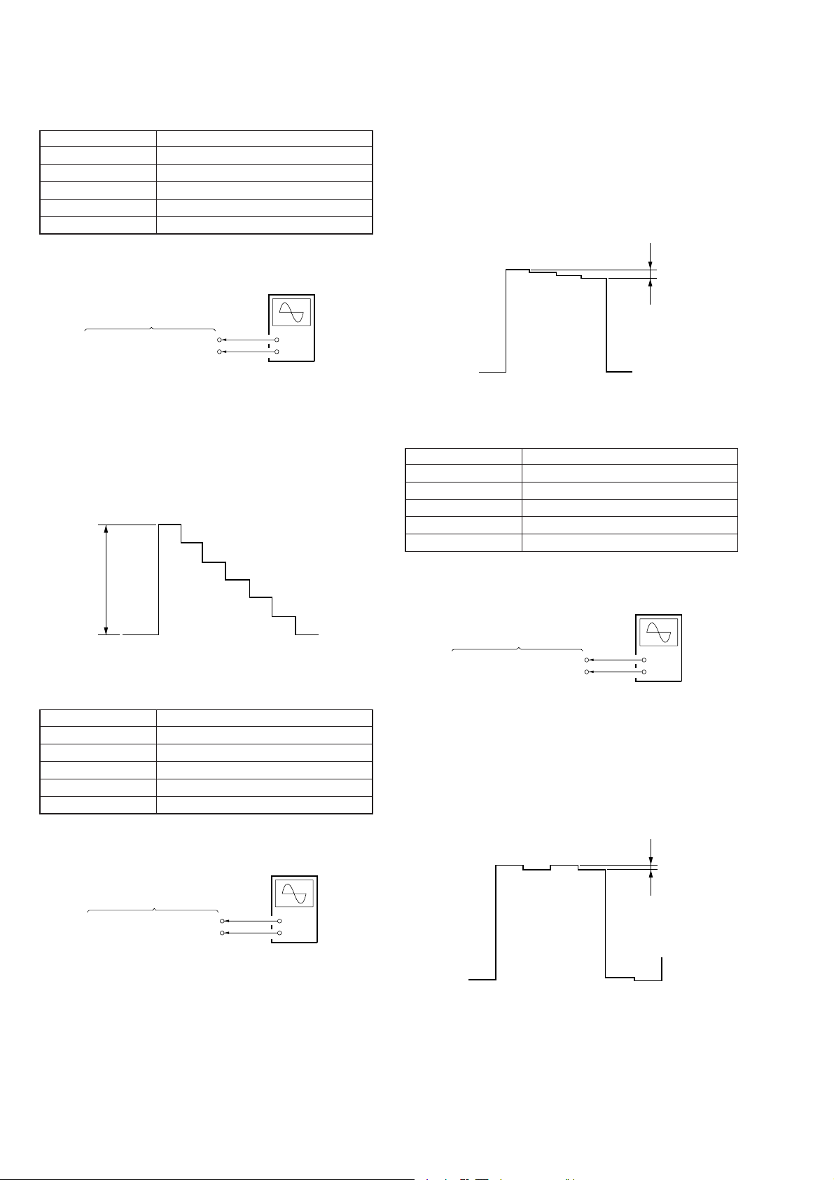
[Video Contrast Adjustment]
Condition:
Input signal 10 step signal (Whie: 100 IRE level)
Measurement point YC-148 board CN1003 pin 8
Measuring equipment Oscilloscope
Adjustment page F
Adjustment address 96
Specification value 0.7 ± 0.02 Vp-p
Adjustment Procedure:
(1) Connect a oscilloscope to the CN1003 pin 8 on the YC-148
board.
(2) Set (or confirm) data: 01 to page 0, address 01. (Cancel F
page protect)
(3) On page F, address: 98, change data with the PLAY and STOP
buttons and press the PAUSE button to write data so that the
C level of wafeform on the oscilloscope satisfies the specification value.
Connection:
YC-148 Board
8
CN1003 pin
CN1003 pin
Adjustment Procedure:
(1) Connect a oscilloscope to the CN1003 pin 8 on the YC-148
(VIDEO G)
1
(GND)
Oscilloscope
(DC range)
+
–
board.
(2) Set (or confirm) data: 01 to page 0, address 01. (Cancel F
page protect)
(3) On page F, address: 96, change data with the PLAY and STOP
buttons and press the PAUSE button to write data so that the
B level of wafeform on the oscilloscope satisfies the specification value.
B
Adjustment and Adjustment Par ts: YC-148 board (see page 3-15)
[Color Adjustment]
Condition:
Input signal Color bar signal
Measurement point YC-148 board CN1003 pin 8
Measuring equipment Oscilloscope
Adjustment page F
Adjustment address 98
Specification value 0 ± 0.02 Vp-p
Connection:
Oscilloscope
(DC range)
C
Adjustment and Adjustment Parts: YC-148 board (see page 3-15)
[Hue Adjustment]
Condition:
Input signal Color bar signal
Measurement point YC-148 board CN1003 pin 8
Measuring equipment Oscilloscope
Adjustment page F
Adjustment address 97
Specification value 0 ± 0.02 Vp-p
Connection:
Oscilloscope
(DC range)
YC-148 Board
8
CN1003 pin
CN1003 pin
Adjustment Procedure:
(1) Connect a oscilloscope to the CN1003 pin 8 on the YC-148
(VIDEO G)
1
(GND)
+
–
board.
(2) Set (or confirm) data: 01 to page 0, address 01. (Cancel F
page protect)
(3) On page F, address: 97, change data with the PLAY and STOP
buttons and press the PAUSE button to write data so that the
D level of wafeform on the oscilloscope satisfies the specification value.
D
YC-148 Board
CN1003 pin
CN1003 pin
8
(VIDEO G)
1
(GND)
+
–
Adjustment and Adjustment Parts: YC-148 board (see page 3-15)
3-8
PC BLOCK
r
E
Signal
Center
GND
• To adjust the PC block, set the PC mode on the set.
• For the PC block adjustment, input a PC RGB signals. (J101 on
the MA-324 board) The pin No. and signal name of J101 is
listed below.
Pin No. Signal Name Pin No. Signal Name
1 Red 9 Sync GND
2 Green 10 GND
3 Blue 11 GND
4–12–
5 GND 13 H-Sync
6 RGB GND 14 V-Sync
7 RGB GND 15 –
8 RGB GND
[H-Sync Frequency Adjustment]
Condition:
Input signal No signal
Measurement point MA-324 board CN206 pin 7
Measuring equipment Frequency Counter
Adjustment page F
Adjustment address 56
Specification value 38 ± 1 kHz
Connection:
Frequency Counte
MA-324 Board
CN206 pin
(INT H)
7\
+
–
[Signal Center Level Adjustment]
Preparation:
Page Address Data Remarks
F 7B 1F BRIGHT (Center)
F 11 03 BRIGHT (Fixed)
Condition:
Input signal SVGA60 Hz: All Black
Measurement point MA-324 board CN206 pin 3
Measuring equipment Oscilloscope
Adjustment page F
Adjustment address 74
Specification value 7.0 ± 0.1 V
Connection:
MA-324 Board
3
CN206 pin
CN206 pin
Adjustment Procedure:
(1) Connect a frequency counter to the CN206 pin 3 on the
(SIG G 1)
9
(GND)
Oscilloscope
(DC range)
+
–
MA-324 board.
(2) Set (or confirm) data: 01 to page: 0, address: 01.
(Cancel F page protect)
(3) On page: F, address: 74, change data with the PLAY and
STOP buttons and press the PAUSE button to write data so
that the E level of waveform on the oscilloscope.
Adjustment Procedure:
(1) Connect a frequency counter to the CN206 pin 7 on the
MA-324 board.
(2) Set (or confirm) data: 01 to page: 0, address: 01.
(Cancel F page protect)
(3) On page: F, address: 56, change data with the PLAY and
STOP buttons and press the PAUSE button to write data so
that the frequency counter reading satisfies the specification
value.
Adjustment and Adjustment Parts: MA-324 board (see page 3-15)
Adjustment and Adjustment Parts: MA-324 board (see page 3-15)
3-9
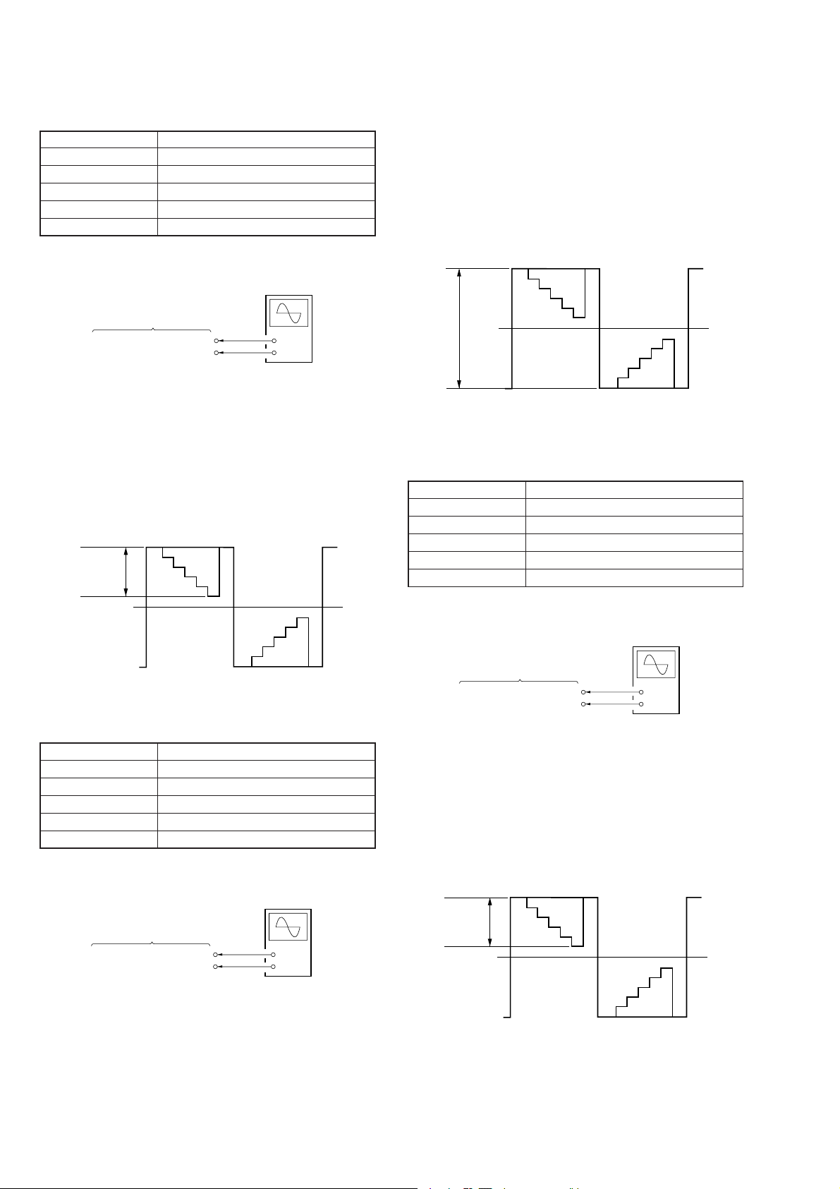
[R Gain Adjustment]
Condition:
Input signal SVGA 60 Hz: RGB 0.7 Vp-p, 16 Step
Measurement point MA-324 board CN206 pin 1
Measuring equipment Oscilloscope
Adjustment page F
Adjustment address 68
Specification value 2.7 ± 0.1 Vp-p
Connection:
Oscilloscope
(DC range)
Adjustment Procedure:
(1) Connect an oscilloscope to the CN206 pin 1 on the MA-
324 board.
(2) Set (or confirm) data: 01 to page: 0, address: 01.
(Cancel F page protect)
(3) On page: F, address: 6B, change data with the PLAY and
STOP buttons and press the PAUSE button to write data so
that the G level of waveform on the oscilloscope satisfies
the specification value.
Black
Level
MA-324 Board
1
CN206 pin
CN206 pin
Adjustment Procedure:
(1) Connect an oscilloscope to the CN206 pin 1 on the MA-
(SIG R 1)
9
(GND)
+
–
324 board.
(2) Set (or confirm) data: 01 to page: 0, address: 01.
(Cancel F page protect)
(3) On page: F, address: 68, change data with the PLAY and
STOP buttons and press the PAUSE button to write data so
that F level of waveform on the oscilloscope satisfies the
specification value.
Black
Level
F
White
Level
Adjustment and Adjustment Parts: MA-324 boar d (see page 3-15)
[R Bias Adjustment]
Condition:
Input signal SVGA 60 Hz: RGB 0.7 Vp-p, 16 Step
Measurement point MA: 324 board CN206 pin 1
Measuring equipment Oscilloscope
Adjustment page F
Adjustment address 6B
Specification value 8.4 ± 0.1 Vp-p
Connection:
Oscilloscope
(DC range)
MA-324 Board
CN206 pin
CN206 pin
1
(SIG R 1)
9
(GND)
+
–
G
Black
Level
Adjustment and Adjustment Parts: MA-324 board (see pag e 3-15)
[G Gain Adjustment]
Condition:
Input signal SVGA 60 Hz: RGB 0.7 Vp-p, 16 Step
Measurement point MA-324 board CN206 pin 3
Measuring equipment Oscilloscope
Adjustment page F
Adjustment address 69
Specification value 2.7 ± 0.1 Vp-p
Connection:
Oscilloscope
(DC range)
MA-324 Board
3
CN206 pin
CN206 pin
Adjustment Procedure:
(1) Connect an oscilloscope to the CN206 pin 3 on the MA-
(SIG G 1)
9
(GND)
+
–
324 board.
(2) Set (or confirm) data: 01 to page: 0, address: 01.
(Cancel F page protect)
(3) On page: F, address: 69, change data with the PLAY and
STOP buttons and press the PAUSE button to write data so
that H level of waveform on the oscilloscope satisfies the
specification value.
Black
Level
H
White
Level
Adjustment and Adjustment Parts: MA-324 board (see pag e 3-15)
3-10
[G Bias Adjustment]
Condition:
Input signal SVGA 60 Hz: RGB 0.7 Vp-p, 16 Step
Measurement point MA-324 board CN206 pin 3
Measuring equipment Oscilloscope
Adjustment page F
Adjustment address 6C
Specification value 8.4 ± 0.1 Vp-p
Adjustment Procedure:
(1) Connect an oscilloscope to the CN206 pin 5 on the MA-
324 board.
(2) Set (or confirm) data: 01 to page: 0, address: 01.
(Cancel F page protect)
(3) On page: F, address: 6A, change data with the PLAY and
STOP buttons and press the PAUSE button to write data so
that the J level of waveform on the oscilloscope satisfies
the specification value.
Connection:
Oscilloscope
(DC range)
MA-324 Board
3
CN206 pin
CN206 pin
Adjustment Procedure:
(1) Connect an oscilloscope to the CN206 pin 3 on the MA-
(SIG G 1)
9
(GND)
+
–
324 board.
(2) Set (or confirm) data: 01 to page: 0, address: 01.
(Cancel F page protect)
(3) On page: F, address: 6C, change data with the PLAY and
STOP buttons and press the PAUSE button to write data so
that the I level of waveform on the oscilloscope satisfies
the specification value.
Black
Level
I
Black
Level
Adjustment and Adjustment Parts: MA-324 board (see page 3-15)
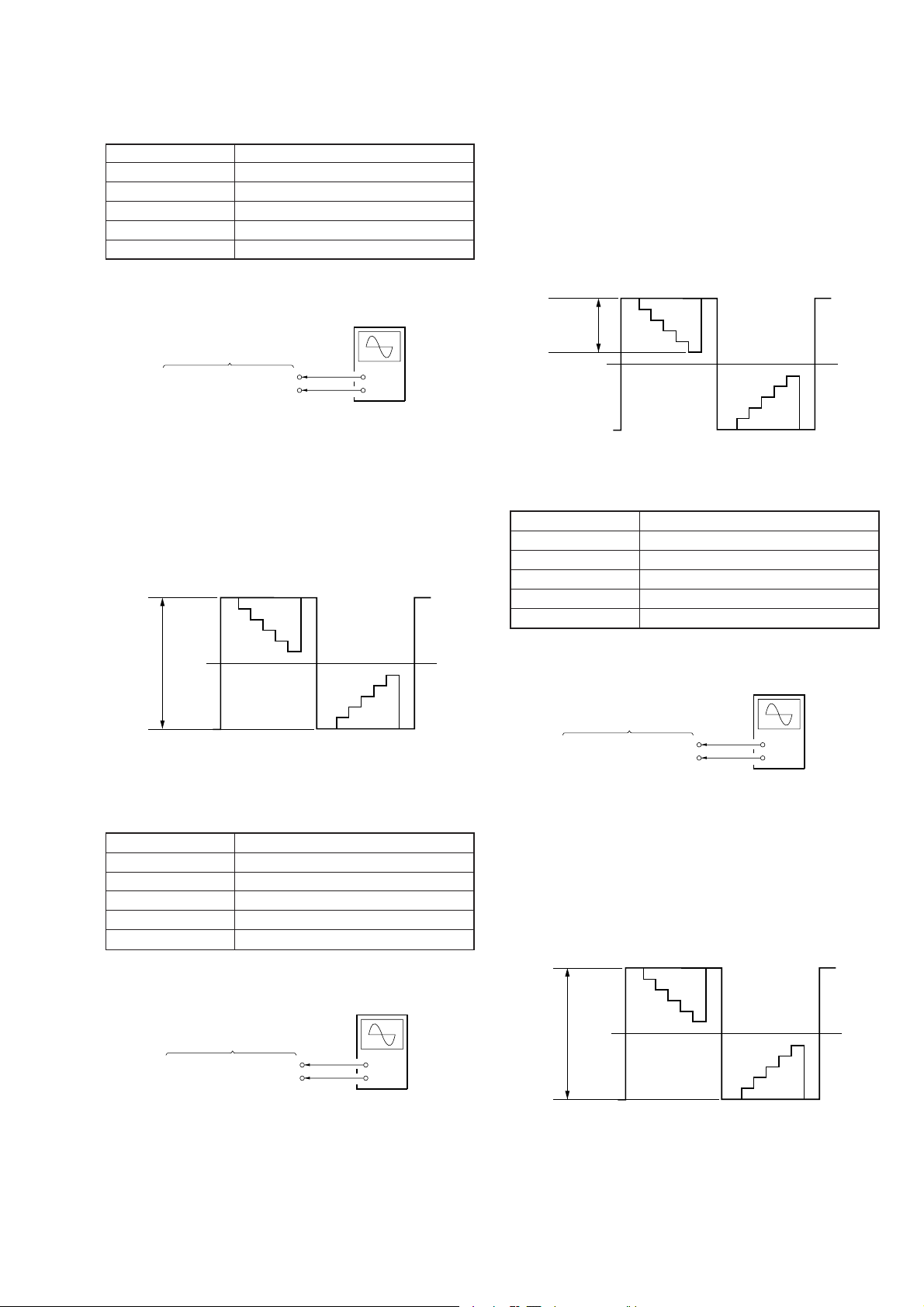
[B Gain Adjustment]
Condition:
Input signal SVGA 60 Hz: RGB 0.7 Vp-p, 16 Step
Measurement point MA-324 board CN206 pin 5
Measuring equipment Oscilloscope
Adjustment page F
Adjustment address 6A
Specification value 2.7 ± 0.1 Vp-p
Connection:
Oscilloscope
(DC range)
Black
Level
J
White
Level
Adjustment and Adjustment Parts: MA-324 board (see page 3-15)
[B Bias Adjustment]
Condition:
Input signal SVGA 60 Hz: RGB 0.7 Vp-p, 16 Step
Measurement point MA-324 board CN206 pin 5
Measuring equipment Oscilloscope
Adjustment page F
Adjustment address 6D
Specification value 8.4 ± 0.1 Vp-p
Connection:
Oscilloscope
(DC range)
MA-324 Board
5
CN206 pin
CN206 pin
Adjustment Procedure:
(1) Connect an oscilloscope to the CN206 pin 5 on the MA-
(SIG B 1)
9
(GND)
+
–
324 board.
(2) Set (or confirm) data: 01 to page: 0, address: 01.
(Cancel F page protect)
(3) On page: F, address: 6D, change data with the PLAY and
STOP buttons and press the PAUSE button to write data so
that the K level of waveform on the oscilloscope satisfies
the specification value.
Black
Level
MA-324 Board
CN206 pin
CN206 pin
5
(SIG B 1)
9
(GND)
K
+
–
Black
Level
Adjustment and Adjustment Parts: MA-324 board (see page 3-15)
3-11
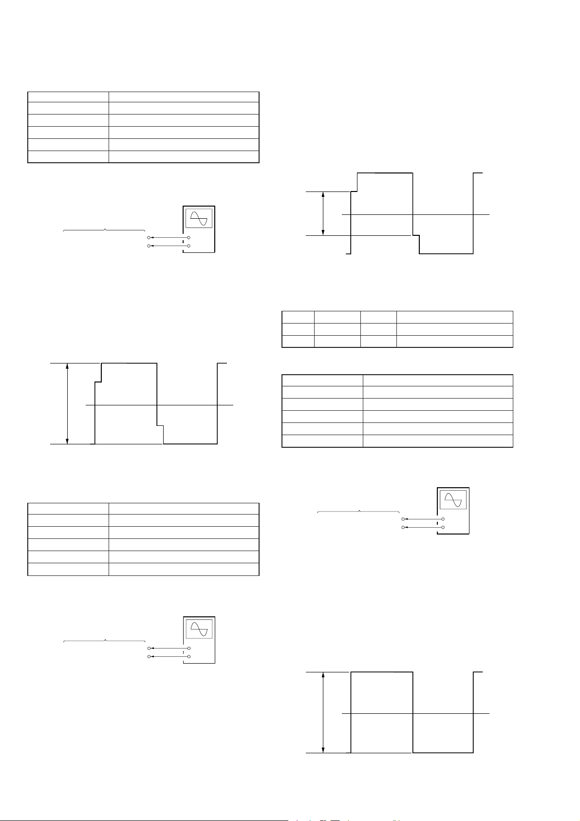
[SID Level Adjustment]
Condition:
Input signal SVGA 60 Hz: RGB 0.7 Vp-p, 16 Step
Measurement point MA-324 board CN206 pin !§
Measuring equipment Oscilloscope
Adjustment page F
Adjustment address 78
Specification value 9.1 ± 0.1 Vp-p
Adjustment Procedure:
(1) Connect an oscilloscope to the CN206 pin !§ on the MA-
324 board.
(2) Set (or confirm) data: 01 to page: 0, address: 01.
(Cancel F page protect)
(3) On page: F, address: 79, change data with the PLAY and
STOP buttons and press the PAUSE button to write data so
that the M level of waveform on the oscilloscope satisfies
the specification value.
Connection:
Oscilloscope
(DC range)
MA-324 Board
CN206 pin
CN206 pin
!§
(P SIG B)
9
(GND)
+
–
Adjustment Procedure:
(1) Connect an oscilloscope to the CN206 pin !§ on the MA-
324 board.
(2) Set (or confirm) data: 01 to page: 0, address: 01.
(Cancel F page protect)
(3) On page: F, address: 78, change data with the PLAY and
STOP buttons and press the PAUSE button to write data so
that the L level of waveform on the oscilloscope satisfies
the specification value.
L
M
Adjustment and Adjustment Parts: MA-324 board (see pag e 3-15)
[Black Limitte Adjustment]
Preparation:
Page Address Data Remarks
F 11 01 Cancel protect of BRIGHT
F 7B 10 Change the BRIGHT level
Condition:
Input signal SVGA 60 Hz: RGB ALL Black
Measurement point MA-324 board CN206 pin 3
Measuring equipment Oscilloscope
Adjustment page F
Adjustment address 7A
Specification value 8.7 ± 0.1 Vp-p
Adjustment and Adjustment Parts: MA-324 boar d (see page 3-15)
[PRG Level Adjustment]
Condition:
Input signal SVGA 60 Hz: RGB 0.7 Vp-p, 16 Step
Measurement point MA-324 board CN206 pin !§
Measuring equipment Oscilloscope
Adjustment page F
Adjustment address 79
Specification value 6.8 ± 0.1 Vp-p
Connection:
Oscilloscope
(DC range)
MA-324 Board
CN206 pin
CN206 pin
!§
(P SIG B)
9
(GND)
+
–
Connection:
MA-324 Board
3
CN206 pin
CN206 pin
Adjustment Procedure:
(1) Connect an oscilloscope to the CN206 pin 3 on the MA-
(SIG G 1)
9
(GND)
Oscilloscope
(DC range)
+
–
324 board.
(2) Set (or confirm) data: 01 to page: 0, address: 01.
(Cancel F page protect)
(3) On page: F, address: 7A, change data with the PLAY and
STOP buttons and press the PAUSE button to write data so
that the N level of waveform on the oscilloscope satisfies
the specification value.
(4) Set data: 1F to page F, address: 7B.
Black
Level
N
Black
Level
Adjustment and Adjustment Parts: MA-324 board (see pag e 3-15)
3-12
[VCOM R Adjustment]
Condition:
Input signal SVGA 60 Hz: RGB 0.7 Vp-p, 16 Step
Measurement point MA-324 board CN206 pin !™
Measuring equipment Degital voltmeter
Adjustment page F
Adjustment address 75
Specification value 6.64 ± 0.02 V
Connection:
Digital Voltmeter
MA-324 Board
CN206 pin
CN206 pin
!™
(COM R)
9
(GND)
+
–
Adjustment Procedure:
(1) Connect a digital voltmeter to the CN206 pin !™ on the MA-
324 board.
(2) Set (or confirm) data: 01 to page: 0, address: 01.
(Cancel F page protect)
(3) On page: F, address: 75, change data with the PLAY and
STOP buttons and press the PAUSE button to write data so
that the digital voltmeter reading satisfies the specification
value.
Adjustment and Adjustment Parts: MA-324 board (see page 3-15)
[VCOM L Adjustment]
Condition:
Input signal SVGA 60 Hz: RGB 0.7 Vp-p, 16 Step
Measurement point MA-324 board CN206 pin !¢
Measuring equipment Digital voltmeter
Adjustment page F
Adjustment address 76
Specification value 6.64 ± 0.02 V
Connection:
Digital Voltmeter
MA-324 Board
CN206 pin
CN206 pin
!¢
(COM L)
9
(GND)
+
–
Adjustment Procedure:
(1) Connect a digital voltmeter to the CN206 pin !¢ on the MA-
324 board.
(2) Set (or confirm) data: 01 to page: 0, address: 01.
(Cancel F page protect)
(3) On page: F, address: 76, change data with the PLAY and
STOP buttons and press the PAUSE button to write data so
that the digital voltmeter reading satisfies the specification
value.
[White Balance Adjustment]
Preparation:
Set data: 1F to page: F, address: 7B.
Condition:
Input signal SVGA 60 Hz: White (50%)
Measurement point LCD R screen
Measuring equipment Video camera
Adjustment page F
Adjustment address 6B, 6D
Specification value With no color
Adjustment Procedure:
(1) LCD R screen on video camera.
(2) Set (or confirm) data: 01 to page: 0, address: 01.
(Cancel F page protect)
(3) Page: F, address: 6B, 6D
Change data at these two addresses with the PLA Y and ST OP
buttons and press the PAUSE button to write data so that the
F page data of looking into the finder.
Adjust it so that the finest white can be seen.
POWER SAVING
[Power Saving Sensor Adjustment]
Mode PC
Signal No signal
Measurement point
Measurement equipment
Adjustment page F
Adjustment address 57
Adjustment Procedure:
(1) Place the specified board 6.5 cm away from sensor.
(2) Set data: 08 to page: F, address 8C.
(3) Find the value when the highest bit of the data on page: 3,
address: 12 changes to “H” with raising the data on page: F,
address: 57 from the initial value data: 40h by 08h.
(4) Set data: 00 to page: 0, address: FF.
(5) Set data: 02 to page: F, address: 8C.
Note: It is necessary to input data: 03 to page: 0, address: FF before read-
ing the data in page: 03. Also without input the data: 00 to page: 0,
address: FF, you cannot input any data to page: F after the data in
page: 3 is read.
Displayed data on adj. remote commander
Adjustment and Adjustment Parts: MA-324 board (see page 3-15)
3-13
POWER SUPPLY BLOCK
[Change Adjustment]
Mode PC
Signal PC AUDIO IN: No signal
Measurement point
Measuring equipment
Adjustment page E, F
Adjustment address 0B, 0C, 0D, 0E (E page)
Connection:
Referring to Fig. 3-4 (see page 3-15), connect the following equipment.
(1) Connect the regulated power supply and a digital voltmeter
to DC IN terminal.
(2) Connect the adjusting remote commander to the CN501 on
MA-324 board.
(3) Connect a PC to the RGB and PC ADUIO IN terminals.
Menu Setting:
(Picture and tone quality standard setting) (see page 3-4)
Adjustment Procedure:
(1) Adjust the output voltage of regulated power supply so that
DC IN terminal voltage (DD-107 board J701) is 8.85 ± 0.01
Vdc.
(2) Turn ON the POWER switch on the set.
(3) Set data: 03 to page: 0, address: FF.
(4) Set data: 0A to page: 2, address: 01.
(5) Read data (XXh) on page: 3, address: 74.
(6) Set data: 00 to page: 0, address: FF.
(7) Set data: 01 to page: 0, address: 01. (Cancel E and F page
protect)
(8) Using the following formulas (calculation of hexadecimal
numbers), calculate the adjustment data and enter them to
respective adjustment addresses.
(Refer to 5. Data Processing on page 3-3)
Page: E Address: 00 E00 = 01
Page: E Address: 01 E01 = XXh
Page: F Address: FE FFE = XXh – 39h
(9) Set data: 00 to page: 0, address: 01.
(10) Connect the regulated power supply and a digital voltmeter
to the battery terminal.
(Keep connecting the regulated power supply to DC IN terminal)
(11) Adjust the output voltage of regulated power supply so that
the battery terminal voltage is 8.35 ± 0.01 Vdc.
(12) Set data: 03 to page: 0, address: FF.
(13) Set data: 0A to page: 2, address: 01.
(14) Read data (YYh) on page: 3, address: 75.
(15) Set data: 00 to page: 0, address: FF.
(16) Set data: 01 to page: 0, address: 01.
(17) Using the following formulas (calculation of hexadecimal
numbers), calculate the adjustment data and enter them to
respective adjustment addresses.
(Refer to 5. Data Processing on page 3-3)
Page: E Address: 02 E02 = YYh
Page: E Address: 03 E03 = YYh – 02h
Page: E Address: 04 E04 = YYh – 55h
Page: E Address: 05 E05 = YYh + 02h
Page: E Address: 06 E06 = DC
Page: E Address: 07 E07 = 05
RGB IN: No signal
VOLUME: Minimum
Displayed data on adj. remote commander
00, 01, 02, 03, 04, 05, 06, 07, 08, 09, 0A,
FE (F page)
Page: E Address: 08 E08 = 08
Page: E Address: 09 E09 = 07
Page: E Address: 0A E0A = B8
Page: E Address: 0B E0B = 0B
Page: E Address: 0C E0C = 60
Page: E Address: 0D E0D = 54
Page: E Address: 0E E0E = 40
(18) Set data: 00 to page: 0, address: 01.
Note: After setting each data, be sure to press the PAUSE button on the
adjusting remote commander.
[Battery Down Adjustment]
Mode PC
Signal PC AUDIO IN: No signal
Measurement point
Measuring equipment
Adjustment page F
Adjustment address 7E, 7F, 80, 81, 82, 83
RGB IN: No signal
VOLUME: Minimum
Displayed data on adj. remote commander
Connection:
Referring to Fig. 3-4 (see page 3-15), connect the following equipment.
(1) Connect the regulated power supply and a digital voltmeter
to the battery terminal.
(2) Connect the adjusting remote commander to the CN501 on
MA-324 board.
(3) Connect a pattern generator to the RGB and PC AUDIO IN
terminal.
Menu Setting:
(Picture and tone quality standard setting) (see page 3-4)
Adjustment Procedure:
(1) Adjust the output voltage of regulated power supply so that
the battery terminal voltage is 6.0 ± 0.01 Vdc.
(2) Turn ON the POWER switch on the set.
(3) Set data: 03 to page: 0, address: FF.
(4) Set data: 0A to page: 2, address: 01.
(5) Read data (ZZh) on page: 3, address: 7D.
(6) Set data: 00 to page: 0, address: FF.
(7) Set data: 01 to page: 0, address: 01. (Cancel F page protect)
(8) Using the following formulas (calculation of hexadecimal
numbers), calculate the adjustment data and enter them to
respective adjustment addresses.
(Refer to 5. Data Processing on page 3-3)
Page: F Address: 7E F7E = ZZh
Page: F Address: 7F F7F = ZZh + 0Ah
Page: F Address: 80 F80 = ZZh + 0Dh
Page: F Address: 81 F81 = ZZh + 10h
Page: F Address: 82 F82 = ZZh + 16h
Page: F Address: 83 F83 = 01
(9) Set data: 00 to page: 0, address: 01.
Note: After setting each data, be sure to press the PAUSE button on the
adjusting remote commander.
3-14
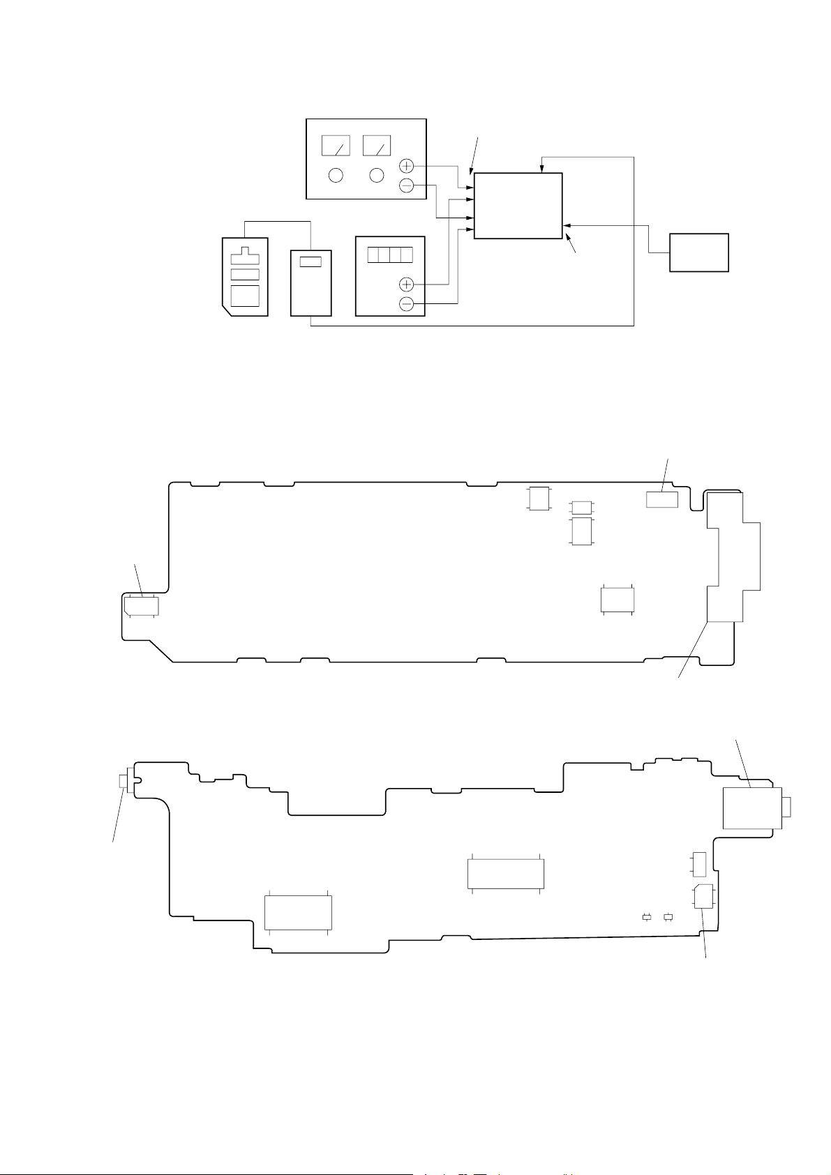
Regulated power supply
Battery
terminal
MA-324 board
(CN501)
Adjusting
Remote
Commander
Extension cable
(J-6082-291-A)
Adjustment and Adjustment Parts:
[MA-324 Board] (Side A)
CN206
For check
connector
Digital
Voltmeter
Fig. 3-4
Set
IC508
MA-324 board
(J101)
YC-148 board
(J1001)
IC502
IC507
PC
CN501
Connect adjusting
remote commander
[YC-148 Board] (Side A)
J1001
AUDIO IN jack
IC1106
IC1001
IC443
Q1001
J101
RGB JACK
J1002
AUDIO/VIDEO jack
CN1004
Q1002
CN1003
For check connector
3-15
3-15 E
SECTION 4
DIAGRAMS
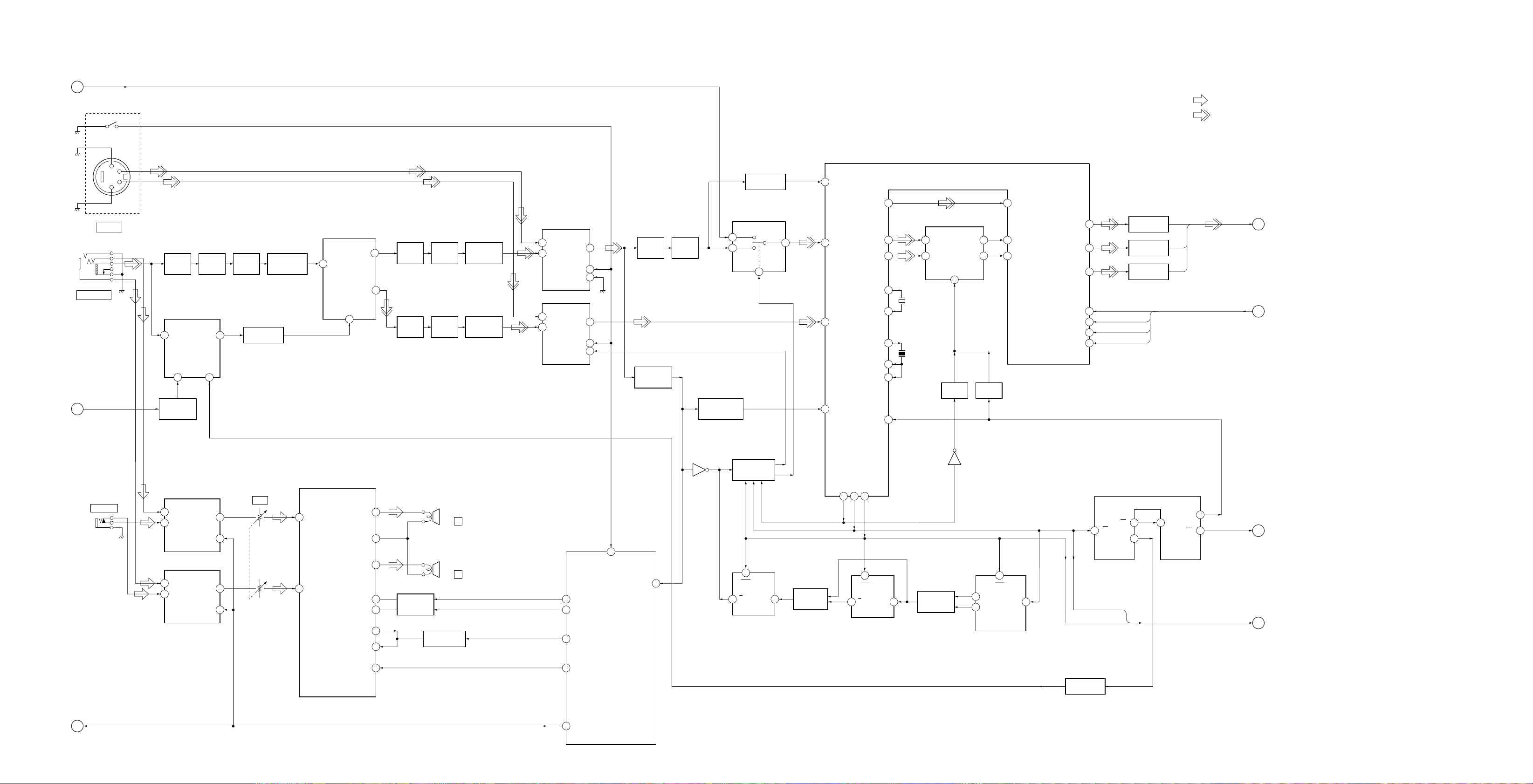
4-1. BLOCK DIAGRAM – AUDIO/VIDEO Section
APC CONT
A
(Page 4-10)
(ON: PLUG IN)
1
Y
3
C
4
2
J1401
S VIDEO
AUDIO/VIDEO
B
(Page 4-10)
J1002
4FSC CONT
VIDEO
BUFFER
Q1003
SYNC GENERATOR
VIDEO
6
17.734475MHz
CLOCK
X1001
4
IC1003
XTAL
CLAMP
D1002,
Q1004
4FSC
7
L.P.F.
FL1001
5
BGATE
Q1005 – 1009
SYNC BUFFER
Q1019 – 1021
VIDEO AMP
Y/C SEPARATOR
IC1002
VIN
18
29
YOUT
COUT
CLK IN
PLM-S700E
• SIGNAL PATH
: AUDIO
: VIDEO
12
13
14
27
29
3
1
2
22
VIDEO RGB DECODER
IC1001
R-Y IN
16
B-Y IN
14
SAND
X1003
4.433619MHz
X1002
500kHz
BUFFER
Q1025
R-Y
B-Y
5
SAMPLE & HOLD
IC1004
11
12
BUFFER
Q1026
Y IN
16
R
G
B
SUB COLOR, CONTRAST,
CONTRAST
COLOR
HUE
VIDEO AMP
Q1033 – 1035
VIDEO AMP
Q1030 – 1032
VIDEO AMP
Q1027 – 1029
R
23
R-Y IN
18
B-Y IN
19
SUB COLOR
CONT
COLOR
HUE
24
G
25
B
SUB COLOR
37
38
20
21
R, G, B
COLOR, HUE
D
(Page 4-5)
E
(Page 4-10)
SYNC BUFFER
Q1024
IC1009, 1010
VIDEO SELECT SWITCH &
VIDEO AMP
IC1010
IN1
5
7
VIDEO
BUFFER
Q1014
VIDEO
BUFFER
Q1010
L.P.F.
FL1003
L.P.F.
FL1002
VIDEO AMP
Q1015 – 1017
VIDEO AMP
Q1011 – 1013
1
3
1
3
IN2
IN2
IN1
IC1009
OUT
SW1
SW2
OUT
SW1
SW2
7
2
4
7
2
4
CLAMP
Q1022
SYNC DETECT
D1001,
Q1001, 1002
VIDEO
BUFFER
Q1018
TIME CONSTANT
APC CONTROL SWITCH
7
6
SWITCH
Q1023
IC1011
1
5
SYNC Y
39
Y
Y
36
C
34
H AFC
4
R-Y
B-Y
FSC OUT
PAL FSC
32FHVCO OUT
32FHVCO IN1
32FHVCO IN2
CLP
C
(Page 4-5)
05
J1001
AUDIO IN
PC/XV AU CONT
IC1301, 1302
LINE SELECT SWITCH &
LINE AMP
IC1302
1
IN1
3
IN2
IN1
1
3
IN2
OUT
SEL
IC1301
OUT
SEL
Q1036
HEADPHONE AMP
IN1
IN2
IC151
OUT1
VREF
OUT2
BB SW
MIX OUT
AVC IN
MUTE SW
4
3
2
LP
9
DBB SWITCH
8
5
6
11
Q153, 154
HP401
(HEADPHONE)
HP402
(HEADPHONE)
AVLS SWITCH
Q156
L
63
R
DBB MID ON
49
DBB NORM ON
50
XAVLS ON
48
AU MUTE
90
PC/XV AU CONT
19
XS DET
SYNC DET
SYSTEM CONTROLLER
IC501 (1/5)
XVIDEO
83
RV1301
VOL
7
2
7
2
13
14
GATE SWITCH
IC1013, 1015,
IC1020
6
CLR
Q
LATCH
IC1012
CK
3 1
SWITCHING
IC1019
BLKHDVD
9 10 11
6
CLR
3 1
Q
LATCH
IC1016
CK
SWITCHING
IC1017
IC1006
MULTIVIBRATOR
IC1005
2Q
7
1Q
1B
5
1Q
6
1
CLR
14
QA
11
QD
COUNTER
IC1014
2
CK
VIDEO H SYNC
VIDEO V SYNC
EDGE DETECT
IC1007, 1008
2A
12
10
9
2Q
VIDEO H SYNC, VIDEO V SYNC
BF
F
(Page 4-5)
G
(Page 4-5)
4-1
4-2
4-3
 Loading...