

Sony PLM-A35E Service manual
PLM-A35E
SERVICE MANUAL
SPECIFICATIONS
Power supply
AC power adaptor: AC-PLM2
100-240 V AC, 50/60 Hz, 16 W
Output voltage 9 V, 1.3 A
Battery pack: NP-F550 (not supplied)
Power consumption
1.8 W Approx.
Operating temperature
5°C to 35°C (41°F to 95°F)
Storage temperature
–10°C to 60°C (14°F to 140°F)
Dimensions
Display unit:
Approx. 173 × 53 × 56 mm
(Approx. 6
(w/h/d, folded up)
Power supply box:
Approx. 53 × 39 × 104 mm
(Approx. 2
(w/h/d)
not including projecting parts and
controls
Mass
Display unit: Approx. 100 g (4 oz)
Power supply box: Approx. 90 g (3.2 oz)
Video signal
PAL colour, EIA standards
7
1
9
/
/
× 2
8
16
× 4
1
/4 inches)
1
/8 inches)
/
8
× 2
1
/
8
× 1
AEP Model
Audio/video input
Special minijack
1 Vp-p, 75 ohms, unbalanced, sync
negative
S video input
4-pin mini DIN
Y: 1 Vp-p, 75 ohms, unbalanced, sync
negative
C: 0.286 Vp-p, 75 ohms, unbalanced, sync
negative
Supplied accessories
AC power adaptor AC-PLM2 (1)
Mains lead (1)
Audio/video cable (special miniplug y
phono plug) (3 m) (1)
Audio/video cable (special miniplug y
stereo miniplug) (0.5 m) (1)
Plug adaptors
(phono jack y phono jack) (3)
Nose piece (black) (1)
Side piece pads (2)
Operating instructions manual (1)
Safety Instructions (1)
Warranty (1)
Design and specifications are subject to
change without notice.
9-928-144-11
GLASSTRON

TABLE OF CONTENTS
1. GENERAL
Glasstron is a Brand-new Concept in
Visual Display.............................................................. 1-1
About the Glasstron ..................................................... 1-1
Locating the Parts and Controls .................................. 1-1
Connecting the Glasstron............................................. 1-1
Wearing the Glasstron.................................................. 1-2
Using the Glasstron...................................................... 1-3
Setting the User Lock .................................................. 1-4
Using an Optional Battery Pack .................................. 1-4
Checking the Supplied Accessories............................. 1-5
Precautions ................................................................... 1-5
2. DISASSEMBLY ...................................................... 2-1
3. ELECTRICAL ADJUSTMENTS...................... 3-1
4. DIAGRAMS
4-1. Block Diagram – AUDIO/VIDEO Section – ............. 4-1
4-2. Block Diagram – LCD Section – ............................... 4-3
4-3. Block Diagram
– KEY CONTROL/POWER SUPPLY Section – ....... 4-5
4-4. Note for Printed Wiring Boards and
Schematic Diagrams .................................................... 4-7
4-5. Printed Wiring Board – YM-A01 Board – ................. 4-9
4-6. Schematic Diagram – YM-A01 Board (1/2) – ............ 4-11
4-7. Schematic Diagram – YM-A01 Board (2/2) – ............ 4-13
4-8. Schematic Diagram – RG-A01 Board –..................... 4-16
4-9. Printed Wiring Board – RG-A01 Board –.................. 4-19
4-10 Pr inted Wiring Board – DL-A01 Board – .................. 4-21
4-11. Schematic Diagram – DL-A01 Board – ..................... 4-23
4-12. Printed Wiring Board – HP-A01 Board – .................. 4-25
4-13. Schematic Diagram – HP-A01 Board – ...................... 4-27
4-14. Printed Wiring Board – DD-A02 Board – .................. 4-29
4-15. Schematic Diagram – DD-A02 Board – ..................... 4-31
4-16. IC Pin Function Description ........................................ 4-41
Notes on chip component replacement
• Never reuse a disconnected chip component.
• Notice that the minus side of a tantalum capacitor may be damaged by heat.
Flexible Circuit Board Repairing
• Keep the temperature of the soldering iron around 270 ˚C during repairing.
• Do not touch the soldering iron on the same conductor of the
circuit board (within 3 times).
• Be careful not to apply force on the conductor when soldering
or unsoldering.
5. EXPLODED VIEWS............................................. 5-1
6. ELECTRICAL PARTS LIST ............................ 6-1
Confidential
SAFETY-RELATED COMPONENT WARNING!!
COMPONENTS IDENTIFIED BY MARK 0 OR DOTTED
LINE WITH MARK 0 ON THE SCHEMATIC DIA GRAMS
AND IN THE PARTS LIST ARE CRITICAL TO SAFE
OPERATION. REPLACE THESE COMPONENTS WITH
SONY PARTS WHOSE PART NUMBERS APPEAR AS
SHOWN IN THIS MANU AL OR IN SUPPLEMENTS PUBLISHED BY SONY.
– 2 –PLM-A35E (AEP)
Glasstron is a brand-new concept in
visual display
Congratulations on your purchase of a Sony
Glasstron Personal Viewer. The Glasstron,
using current technology in small,
lightweight visual displays, provides a
television viewing experience similar to
watching a 52-inch television from a
distance of approximately 2 m (6.6 feet).
(Viewing experience may differ according
to individual perception.)
The Glasstron Personal Viewer creates an
image through two separate liquid crystal
displays, in close proximity to your eyes.
To insure your safe use of the Glasstron,
please become familiar with its basic
operations, including proper fitting
instructions, and be aware of any symptoms
of eye fatigue or other discomfort you may
experience.
WARNING
YOUR FAILURE TO FOLLOW THESE
OPERATING INSTRUCTIONS MAY
RESULT IN EYE FATIGUE, EYE
IMPAIRMENT, OR OTHER EYE INJURY,
PROPERTY DAMAGE OR DEATH.
WARNING
THIS PRODUCT SHOULD NOT BE USED
BY CHILDREN AGE 15 OR YOUNGER.
THE EYES OF CHILDREN ARE STILL
DEVELOPING AND MAY BE ADVERSELY
AFFECTED FROM USE OF THIS
PRODUCT.
Note on the LCD (Liquid Crystal
Display)
The LCD screen is made with highprecision technology. However, black
points or bright points of light (red, blue,
or green) may appear constantly on the
LCD screen. This is not a malfunction.
(Effective dots: more than 99.99%)
SECTION 1
GENERAL
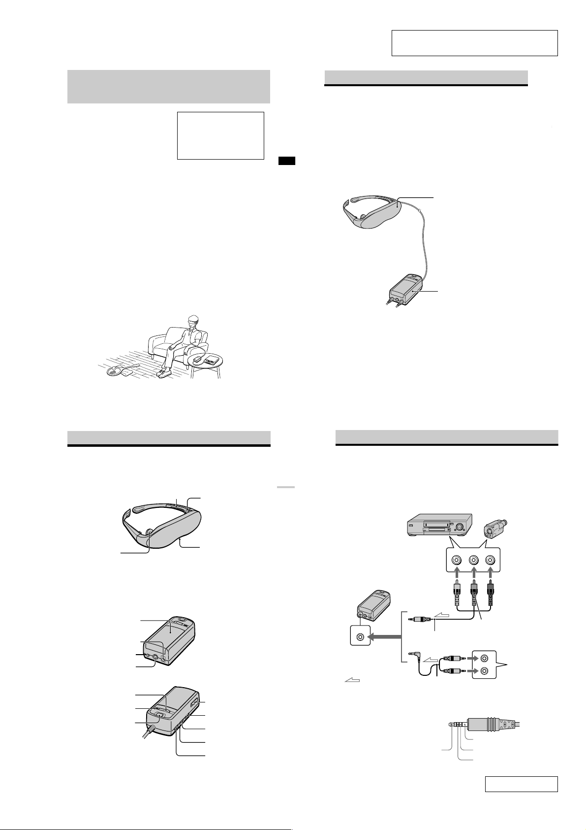
About the Glasstron
Caution: The screen is always right in front of you.
The Glasstron is a face-mounted display. With this type of display, the screen is always in front
of you, even if you move your head. Because of this feature, you can concentrate on the screen
more easily compared with ordinary TVs, and you have a sense of being in the action.
• It is easy to adjust the Glasstron to your eyes. You can use the display unit even while wearing
glasses.
• Every time you use the Glasstron, the adjustment screen appears to help you adjust the
GB
display unit properly. You can also check whether the left and right screen positions are
properly aligned or not.
• If you keep using the Glasstron continuously for three hours, a warning appears on the screen
and the power will turn off automatically.
The Glasstron consists of the following items:
This section is extracted from instruction
manual (3-868-186-31).
Getting Started
Display unit
The display unit is equipped with two
small (left and right) LCDs.
Power supply box
You can use Sony’s recommended
optional battery pack. You can also use
the house current. To use the Glasstron,
connect your video equipment to A/V
IN on the power supply box.
Locating the parts and controls
Refer to the pages indicated in parentheses ( ) for details.
Display unit
Earphone (14)
Power supply box
Cover (20)
DC IN 9V connector (11)
A/V IN (audio/video) jack
(8, 9)
S VIDEO IN jack (10)
POWER ON/OFF switch (15)
POWER lamp (15)
START/BATT CHECK button
(16, 21)
Side piece (12)
Side piece
adjuster (13)
Nose piece (12)
BATT/COVER RELEASE
button (20)
BRIGHT (brightness)
control (17)
VOL (volume) control (17)
User lock switch (19)
AVLS ON/OFF switch (18)
-GB
3
Getting Started
-GB
7
Features
• A powerful, big screen experience
comparable to watching a 52-inch screen
from approximately 2 m (6.6 feet) away.
• Handy portable folding display.
• The display unit weighs only 100 g (4 oz).
• Approximate continuous use for up to
seven hours with Sony’s recommended
battery pack, NP-F550.
Connecting the Glasstron
Connecting video equipment
Connect a VCR, laser disc player, DVD player, or camcorder to the power supply box as shown
below. Two AV cables are supplied. Select the correct AV cable according to the shape of the
connectors on the unit to be connected.
VCR, laser disc player, DVD player, camcorder, etc.
to audio/video outputs
(phono jack)
Power supply box
A/V IN
to A/V IN
(special minijack)
: Signal flow
About the audio/video input jack
The audio/video input jack of the Glasstron is a
special minijack, and the signal connections are
aligned as shown on the right. This alignment
may differ depending on the equipment.
-GB
8
Video
(yellow)
Audio/video cable
(special miniplug y phono
plug) (supplied)
Audio/video cable (special
miniplug y stereo miniplug)
(supplied)
Video (yellow)
Audio (black)
Audio L
Audio R
(red)
Audio L
(white)
to video output
(minijack)
to audio output
(stereo minijack)
Audio R
GND
Video
DVD player,
Video CD
player
-GB
5
Confidential
1-1 PLM-A35E (AEP)
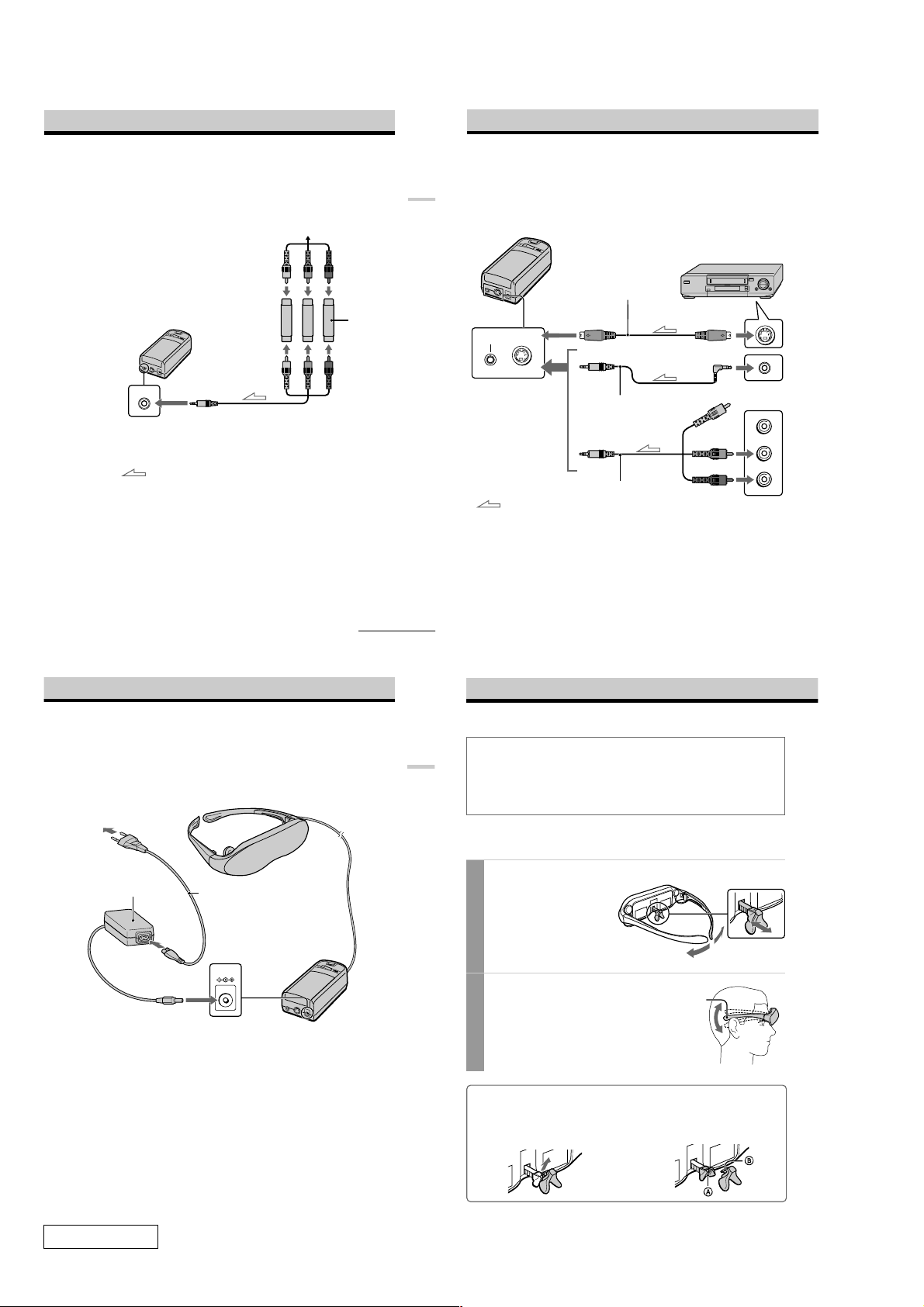
Connecting other equipment
The plug adaptor (phono jack y phono jack) is supplied. Use the plug adaptor according to the
equipment you want to connect.
TV game, DVD player, camcorder, etc.
Plug adaptor
(supplied)
A/V IN
Audio/video cable
to A/V IN
(special minijack)
(special miniplug y phono plug)
(supplied)
Getting Started
Connecting the Glasstron (continued)
If your video equipment has an S video jack
We recommend connecting the Glasstron to your video equipment using an S video cable and the
audio/video cable to enjoy the highest quality pictures. In this case, you do not need to connect the
video (yellow) plug. If you connect both the S video and video plugs, the S video signal is
automatically selected.
Power supply box
VCR, laser disc player, DVD player,
camcorder, etc.
S video cable
(not supplied)
A/V IN
S VIDEO IN
to A/V IN
to S VIDEO IN
Audio/video cable
(special miniplug y special
miniplug) (not supplied)
to S video output
to audio/video output
Video (yellow)
Audio L (white)
: Signal flow
continued
Connecting the power source
Connect the AC power adaptor AC-PLM2 (supplied) to mains. Do not connect the power source
until all other connections are complete.
to DC IN 9V
Display unit
Mains lead
(supplied)
DC IN 9V
Power supply box
to mains
AC power adaptor
AC-PLM2 (supplied)
-GB
9
Getting Started
Audio R (red)
Audio/video cable
: Signal flow
Notes
•Even if you use the supplied audio/video
cable, the audio and video signals may not be
carried to the Glasstron depending on the
video source. In this case, contact your Sony
dealer or local authorized Sony service
facility.
-GB
10
(special miniplug y phono plug)
(supplied)
•When you connect the Glasstron to the audio
output jacks (phono jacks) of your video
equipment, connect the Glasstron to both the
right and left audio output jacks. If you
connect the Glasstron to just one audio output
jack, you will hear sound from only one of the
stereo earphones.
to audio/video outputs
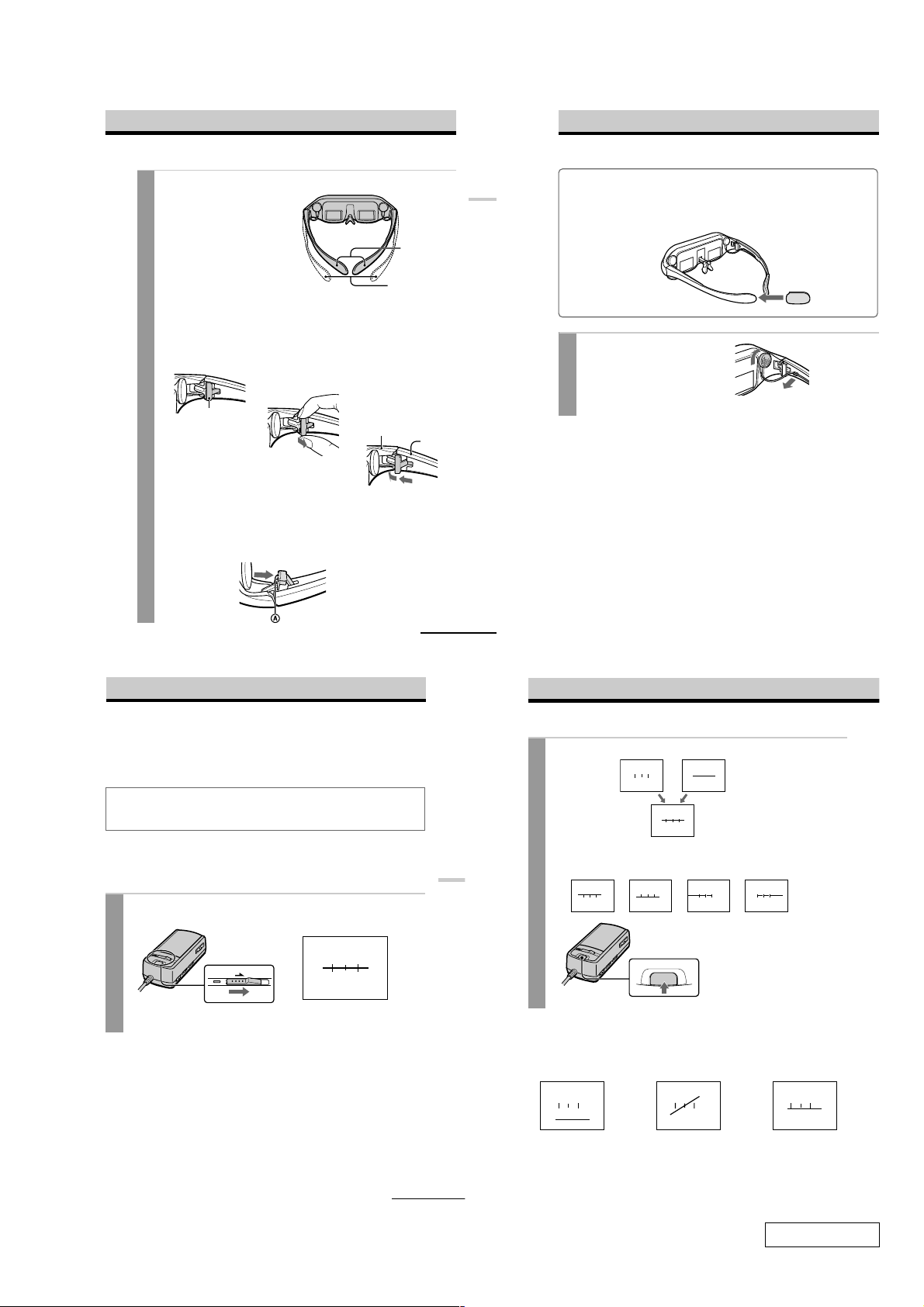
Wearing the Glasstron
WARNING
• Failure to properly fit the product (see “Proper Fit,” page 5 on the Safety Instructions) each
time may result in eye fatigue, eye damage, or loss of visual functions and may result in
accident or injury.
• This product should not be used by children age 15 or younger.
The eyes of children are still developing and may be adversely affected by use of this
product, and it may cause eye fatigue, eye damage, or loss of visual functions.
In addition, this product may not be adjusted to fit a child’s head.
If you normally wear glasses while watching TV, you can use the Glasstron while wearing
glasses. When you take the Glasstron off, be careful that your regular glasses not get caught on
the Glasstron.
Adjust the nose piece and put on the Glasstron.
1
Pull out the nose piece if you wear
glasses.
Open the side pieces by grasping the
side piece tips and put on the
Glasstron.
Caution:
Be careful not to poke your eyes
with the side piece tips when
putting the Glasstron on or off.
Adjust the angle of the display unit.
2
Adjust the angle of the side pieces by
grasping the side piece tips to adjust the
display unit to the most suitable viewing
position.
You do not necessarily have to rest the
side pieces on your ears.
Side piece
Nose piece
Confidential
To use the supplied nose piece
If you are still unable to have a full view of the screen or clear picture colour on the Glasstron after
performing step 2 above, replace the nose piece with the supplied nose piece (black).
1 Remove the nose piece in an upward direction
while grasping the nose piece support.
-GB
11
-GB
12
2 Insert B of the supplied nose piece
(black) into the round notch A.
1-2PLM-A35E (AEP)
Adjust the width of the side pieces.
3
There are two settings for the side piece
width adjustment.
If the fit seems loose, insert the side
piece adjusters to the hinges of the left
and right side pieces.
To use the side piece adjusters
1 This is the original
position. Normally keep
adjusters here.
Side piece adjuster
To reset the side piece adjusters, turn the side pieces inside slightly and reverse the
above procedure.
To put the side piece adjuster back, press A to the illustrated direction until it “clicks”
into place.
2 Turn the side pieces
inside slightly then
gently squeeze the top
and bottom of the side
piece adjuster and pull
out to release.
3 Slide the side piece
adjuster toward the
display unit.
4 Reinsert the side piece
adjuster tines into the
hinge area between the
side piece and display
unit. Repeat the
procedure for the other
side piece.
Display unit
Using side piece
adjusters
Not using side piece
adjusters
Side piece
4
3
Getting Started
Wearing the Glasstron (continued)
For increased comfort while wearing Glasstron
If the Glasstron fit is loose or uncomfortable, place the supplied side piece pads onto the tip of each
side piece.
Note
Use the side peace pads pocket-side inward.
Wear the stereo earphones.
4
Detach the stereo earphones from the
display unit and put them in your ears.
Notes
•If the stereo earphones are loose, we
recommend using the spare ear-pads (not
supplied).
•If your head is small, you may not be able to
use the Glasstron.
•Depending on your eyesight, you may not be
able to focus on the picture properly. In such
a case, it is not a malfunction.
Using the Glasstron
If you set the user lock, unlock it (page 19).
Before you start…
Be sure to follow the procedures in “Connecting the Glasstron” (pages 8 - 11) and “Wearing the
Glasstron” (pages 12 - 14).
WARNING
Each time you use this product, adjustment screens will appear, requiring the viewer to
properly fit the product. To prevent eye damage, do not use this product if the vertical lines
do not cross the horizontal line on the next screen.
The Glasstron includes two small (left and right) LCDs. You are watching a combined picture
created from these two screens. Although the screen position is properly aligned at the factory, it
may become misaligned if the Glasstron is deformed or damaged. Check the screen position
alignment every time you turn on the Glasstron. If you cannot have correct screen alignment,
stop using the Glasstron immediately.
Turn on the Glasstron using the POWER ON/OFF switch.
1
The POWER lamp lights up.
POWER
ON/OFF
Screen
continued
Operations
-GB
13
-GB
14
Using the Glasstron (continued)
If the screens are aligned, press the START/BATT CHECK button.
2
If the image you see matches one of the pictures
below, stop using the Glasstron immediately.
Left screen Right screen
The combined picture
you see with both eyes
If the image you see matches one of the pictures below, you have
correct screen alignment.
Correct Correct Correct Correct
Correct
START/BATT CHECK
You may see a horizontal line
on the left screen rather than
the right screen and vertical
lines on the right screen
rather than the left screen.
This is not a malfunction.
Use of the Glasstron under such conditions may cause
eye fatigue or eye damage.
Incorrect Incorrect Incorrect
continued
When no vertical lines
cross the horizontal
line.
If you cannot see a proper arrangement of these lines even after resting your eyes for a
few hours, the Glasstron may not be operating correctly. Contact your Sony dealer or
local authorized Sony service facility.
-GB
15
-GB
16
When the horizontal
line appears as a
diagonal line.
When the centre vertical
line does not cross the
horizontal line.
Confidential
1-3 PLM-A35E (AEP)
Start playback on the video equipment connected to the
3
Glasstron.
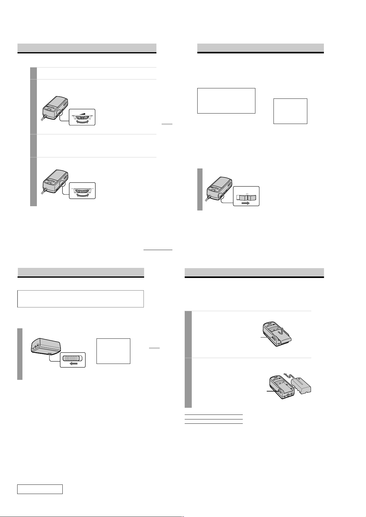
Adjust the volume by turning the VOL control.
4
When you set the AVLS ON/OFF switch to ON, you cannot turn up the volume beyond
the defined limit (see page 18).
VOL
lower louder
Check that the four corners of the screen are clear.
5
If the four corners of the screen are not clear, do the step 2 (page 16) to check the screen
position alignment again.
Adjust the brightness by turning the BRIGHT control.
6
BRIGHT
·µ
less bright brighter
Operations
Using the Glasstron (continued)
After you finish using the
Glasstron
Take off the Glasstron, and turn off the
power.
Note on the LCDs
The LCD screen is made with highprecision technology. However, black
points or bright points of light (red, blue, or
green) may appear constantly on the LCD
screen. This is not a malfunction.
(Effective dots: more than 99.99%)
Preventing sound from
escaping through the stereo
headphones
–– AVLS (Auto Volume Limiter
System):
Keeps down the maximum volume to
protect your ear. You cannot turn up the
volume beyon d the defined limit even if
you try to turn it up.
Set the AVLS ON/OFF switch
to ON.
AVLS
OFF ON
To turn the AVLS off
Set the AVLS ON/OFF switch to OFF.
Screen warnings against
overuse of the Glasstron
To prevent eye fatigue or eye damage, after
you use the Glasstron for three hours the
following caution appears on the screen and
the power turns off automatically.
TIME OUT
ZEIT ZU ENDE
TEMPS DEPASS
Caution: Motion sickness from
viewing programmes.
Some viewers may experience motion
sickness, headache or nausea from viewing
movies or video programmes, especially
those with intense action and movement. If
you feel any of these symptoms, stop using
the product immediately. To avoid personal
injury or injury to others, do not drive a car
or motorcycle, nor do anything that requires
concentration until the symptoms
disappear.
Caution: Motion sickness from
external motion.
Do not use the product while subject to
external motion –– for example, as a
passenger in a car. Use of this product
under these conditions may cause motion
sickness.
Setting the user lock
WARNING
This product should not be used by children age 15 or younger. The eyes of children are still
developing and may be adversely affected by use of this product. To prevent such use, this
product is equipped with the user lock system.
When the user lock is on, audio and video signals are not input and all operations except power
on/off are disabled.
To use the Glasstron, unlock the user lock.
Set the user lock switch as shown in the illustration.
USER LOCK
BEN. –SPERRE
VERR. UTILIS
Bottom of the Power
supply box
To unlock the user lock
Set the user lock switch to the opposite position.
Lock
Unlock
continued
Operations
-GB
17
-GB
18
Using an optional battery pack
If you use a battery pack such as the NP-F550/F750/F950, you can use the Glasstron without
connecting to mains.
Charge the battery pack before use by using the optional battery charger, BC-V615. You cannot
charge the battery pack while it is on the unit.
Slide the BATT/COVER RELEASE button to remove the cover.
1
When not using the unit, keep the cover
on the power supply box.
BATT/COVER RELEASE
button
Attach the battery pack to the power supply box.
2
Install the battery pack properly making
sure it is not crooked against the power
supply box.
To remove the battery pack, slide and
hold the BATT/COVER RELEASE
button and pull the battery pack off.
Battery pack Battery life
NP-F550 Approx. 7 hours
* The above indications are for fully charged
batteries.
* Actual battery life depends on conditions of
use.
* You can also use a battery pack such as the
NP-F530/F730/F750/F930/F950 (not
supplied) with the Glasstron.
* You can use an “InfoLITHIUM™” battery
pack with the Glasstron. When using such a
battery pack, the estimated remaining battery
life is displayed with the indicator instead of
the time counter.
Power supply box
BATT/COVER RELEASE
button
Notes
• While using the battery pack, if you connect
or disconnect the AC power adaptor, the
power turns off. To turn the power on, press
the POWER ON/OFF switch again.
• If the POWER lamp flashes while using the
battery pack, replace the battery pack with a
fresh one.
• Battery life may be shorter in a cold
environment. This is a typical battery
characteristic.
“InfoLITHIUM” is a trademark of Sony
Corporation.
Battery pack
Confidential
-GB
19
-GB
20
1-4PLM-A35E (AEP)
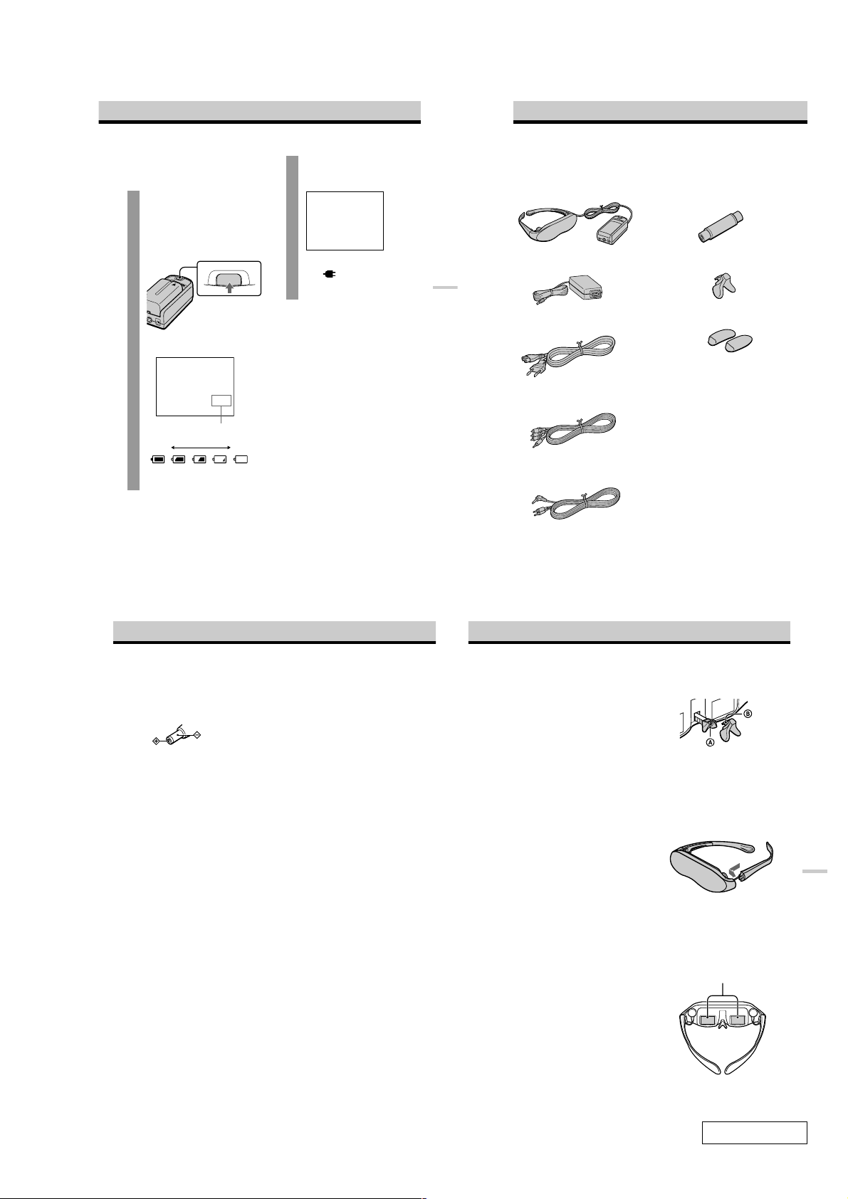
Checking the remaining
battery life
When no indication or
caution appears on the
screen, press the START/
BATT CHECK button.
The remaining battery life appears
and the picture disappears.
START/BATT CHECK
When the battery pack is weak, the
following message appears on the
screen. Replace the battery pack with
a charged one.
BATTERY DOWN
AKKU LEER
PILE PLATE
When using the AC power adaptor,
the “
” mark appears on the
screen.
Operations
Checking the supplied accessories
Check that the following accessories are supplied with your Glasstron. If any item is not
supplied, contact your Sony dealer or local authorized Sony service facility.
• Display unit/Power supply box (1)
• AC power adaptor AC-PLM2 (1)
• Plug adaptors
(phono jack y phono jack) (3)
• Nose piece (black) (1)
Fully
charged
Remaining battery life
dead
Precautions
Use
• Operate the product only with the
supplied AC power adaptor (AC-PLM2).
If you use a different AC power adaptor, it
may cause a malfunction.
Unified polarity plug
• Should any liquid or solid object fall into
the cabinet, unplug the product and have
it checked by qualified personnel before
operating it further.
• Always turn the product off when you do
not use it.
Unplug the product from the mains if you
are not going to use it for several days or
more. To disconnect the cord, pull it out
by the plug. Never pull the cord itself.
• Do not overload mains, extension cords,
or convenience receptacles beyond their
capacity, since this can result in fire or
electric shock.
• Do not use attachments not recommended
by the manufacturer, as they may cause
hazards.
• Avoid using earphones at high volume.
Hearing experts advise against
continuous, loud, and extended play. If
you experience a ringing in your ears,
reduce volume or discontinue use.
• Do not touch the AC power adaptor or
power supply box with wet hands. If you
fail to observe this, it may cause electric
shock.
• Do not drop or give a mechanical shock to
the product.
Installation
• To prevent internal heat buildup, do not
block the ventilation openings.
• Avoid operating the product at
temperatures below 5°C (41°F).
• Do not subject the product to high
temperature or direct sunlight. If you do
not observe the above instructions, the
product may become deformed and the
screens may become impossible to align.
If you keep watching misaligned screens,
you may develop eye fatigue. Follow the
instructions in “Using the Glasstron”
(pages 15 - 18), to be sure the screens are
aligned. If you find the screens
misaligned, have the product repaired at
your Sony dealer or local authorized
Sony service facility.
• Do not place the product in locations
where it is wet, humid, dusty, smoky, or
steamy. Do not use this product near or
around water. It may cause fire or electric
shock. Especially, do not use the product
in the bathroom.
• If the product is transported directly from
a cold to a warm location, or if the room
temperature has changed suddenly, the
picture may be blurred or show poor
colour. This is because moisture has
condensed on the lenses inside. If this
happens, let the moisture evaporate
before using the product.
• Do not place the product on an unstable
cart, stand, table, or shelf. The product
may fall, causing serious injury to a child
or an adult, and serious damage to the
product.
• Do not allow anything to rest on or roll
over the power cord, and do not place the
product where the power cord is subject
to wear or abuse.
Others
• Unplug the product from the wall outlet
and refer servicing to qualified service
personnel under the following conditions:
- When the power cord or plug is
damaged or frayed.
- If liquid has been spilled into the
product.
• Mains lead (1)
• Audio/video cable
(special miniplug y phono plug) (1)
• Audio/video cable (special miniplug y
stereo miniplug) (1)
-GB
21
-GB
6
- If the product has been exposed to rain
or water.
- If the product has been subject to
excessive shock by being dropped, or
the cabinet has been damaged.
- If the product does not operate
normally when following the operating
instructions. Adjust only those controls
that are specified in the operating
instructions. Improper adjustment of
other controls may result in damage
and will often require extensive work
by a qualified technician to restore the
product to normal operation.
- When the product exhibits a distinct
change in performance –– this indicates
a need for service.
• Do not disassemble or modify the
product. It may cause fire or electric
shock. Have the product checked and
repaired at your Sony dealer or local
authorized Sony service facility.
• Do not attempt to service the product
yourself since opening the cabinet may
expose you to dangerous voltage or other
hazards. Refer all servicing to qualified
service personnel.
• When replacement parts are required, be
sure the service technician certifies in
writing that he has used replacement
parts specified by the manufacturer that
have the same characteristics as the
original parts.
Unauthorized substitutions may result in
fire, electric shock, or other hazards.
• Upon completion of any service or
repairs to the product, ask the service
technician to perform routine safety
checks (as specified by the manufacturer)
to determine that the product is in safe
operating condition, and to so certify.
• Unplug the product from the mains
before cleaning. Clean the product gently
with a dry, soft cloth, or a soft cloth
slightly moistened with a mild detergent
solution. Do not use any type of solvent,
such as alcohol or benzine.
• Side piece pads (2)
• Operating instructions manual (1)
• Safety Instructions (1)
• Warranty (1)
If the nose piece is disconnected
Reinsert the nose piece to its position.
Insert B to A.
If the side pieces are
disconnected
You can reattach the side piece.
Insert the side piece to the inner side of the
display unit. Gently push until it clicks into
position.
However, reattaching the side pieces may
cause a malfunction. Be careful not to
reattach them too often.
Window coating
To avoid reflection, the windows are coated.
Do not place the product in locations subject
to sudden temperature changes, or where it
is excessively hot (above 60ºC/96ºF). For
example, inside a car parked in direct
sunlight.
The coating may develope cracks.
Windows
Additional Information
-GB
22
-GB
23
Confidential
1-5 PLM-A35E (AEP)

MEMO
Confidential
1-6PLM-A35E (AEP)
(END)
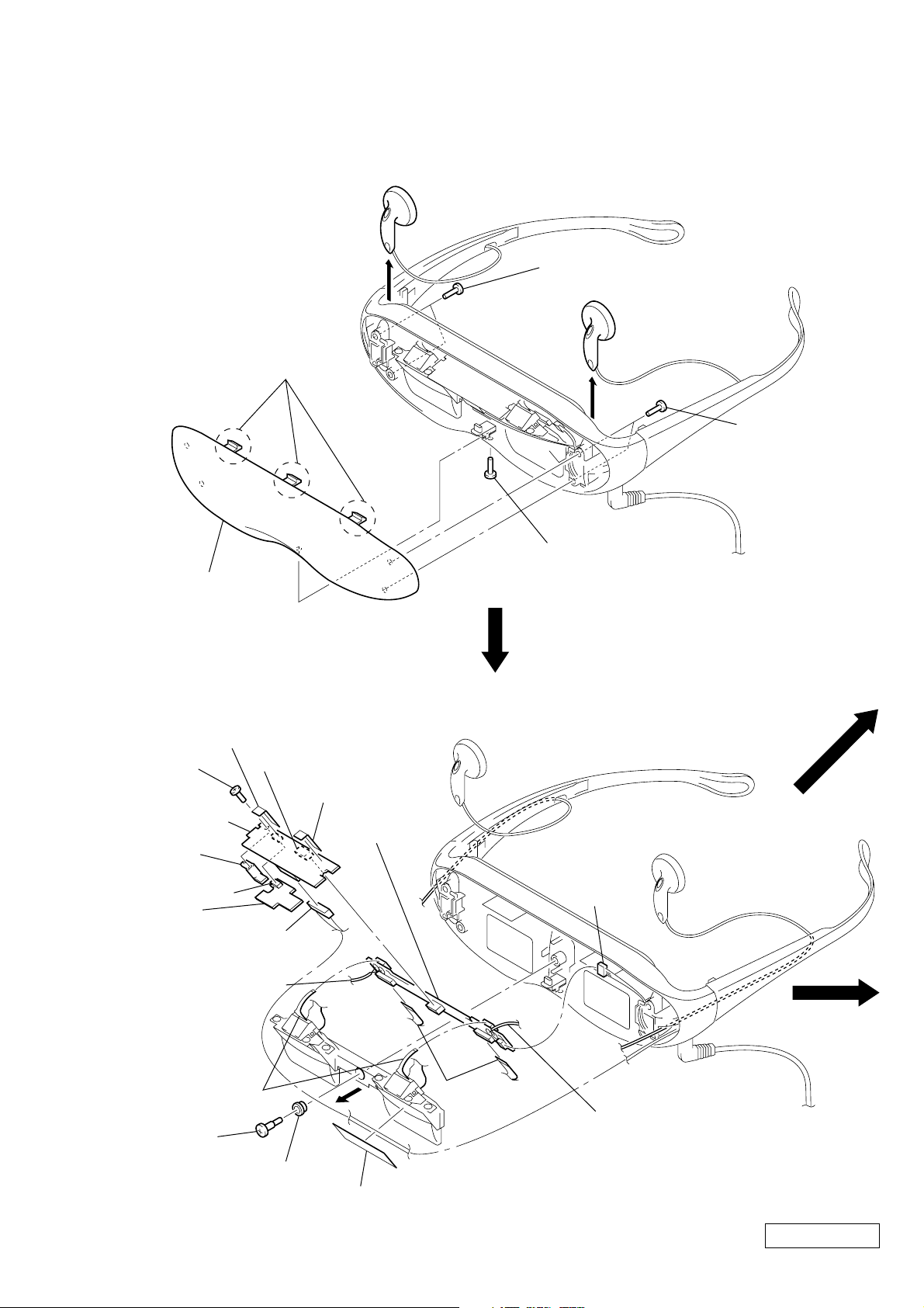
SECTION 2
)
qd connector
(CN704)
5 connector (CN801)
q; connector (CN901)
7 connector
(CN701)
6 unweaved cloth
6 unweaved cloth
qf two flexible boards
(CN705, 706)
qg two flexible boards
(CN702, 703)
1 step screw
3 sheet
2 insulator
4
qj HP-A01 (C)
MOUNTED PWB
qs RG-A01 (C)
COMPLETE PWB
qh Remove two solders of
ear MDR-E805PT//K SET
receiver (HEADPHONE (R)).
qh Remove two solders of
ear MDR-E805PT//K SET
receiver (HEADPHONE (L)).
qa DL-A01
COMPLETE PWB
9 PC board holder
8 screw
(PTT1.7 × 6)
DISASSEMBLY
Note: Follow the disassembly procedure in the numerical order given.
CABINET (FRONT)
1
4 three claws
5 cabinet (front)
2 two screws
(PTT1.7 × 6)
1
2 two screws
3 screw
(PTT1.7 × 6)
RG-A01 (C) COMPLETE PWB, HP-A01 (C) MOUNTED PWB, DL-A01 COMPLETE PWB
(PTT1.7 × 6
Confidential
2-1 PLM-A35E (AEP)
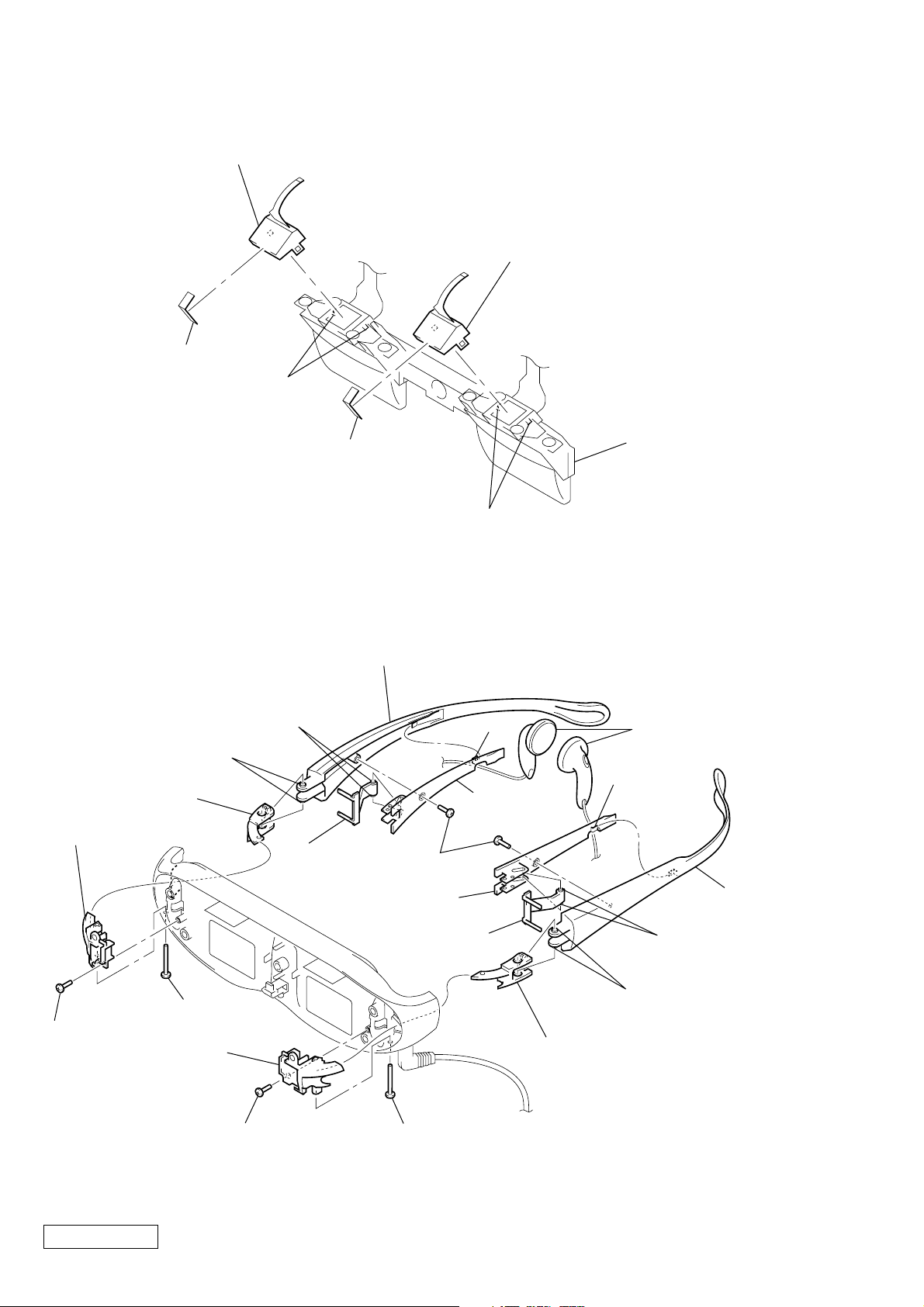
BACK LIGHT UNIT
k
3 back light unit
3 back light unit
1 unweaved cloth
2 two claws
1 unweaved cloth
EAR MDR-E805PT//K SET RECIVER (HP701, 702)
qa vine (R)
7 two bosses
9 two bosses
q; hinge bearing (R)
3 hinge block (R)
8 adjustor
4 two screws
6 vine cover (L)
2 two claws
(PTT1.7 × 6)
5 claw
6 vine cover (R)
4 lens bloc
qs two ear MDR-E805PT//K SET
recivers (HEADPHONE (L/R))
5 claw
qa vine (L)
2 screw (PTT1.7 × 6)
3 hinge block (L)
Confidential
1 screw
(PTT2 × 20)
2 screw
(PTT1.7 × 6)
8 adjustor
1 screw
(PTT2 × 20)
2-2PLM-A35E (AEP)
(END)
7 two bosses
9 two bosses
q; hinge bearing (L)
SECTION 3
)
r
ELECTRICAL ADJUSTMENTS
Precautions on adjustment:
1. Perform the adjustment in the given order.
2. Power supply voltage: DC 9 V
3. Equipment required
Electrical adjustment requires the following measuring equipment.
(1) Oscilloscope: 2 phenomena, band 30 MHz or more, with de-
lay mode (use 10 : 1 probe unless otherwise specified)
(2) Pattern generator
(3) Regulated power supply
(4) Digital voltmeter
(5) Frequency counter
(6) Connector for adjustment
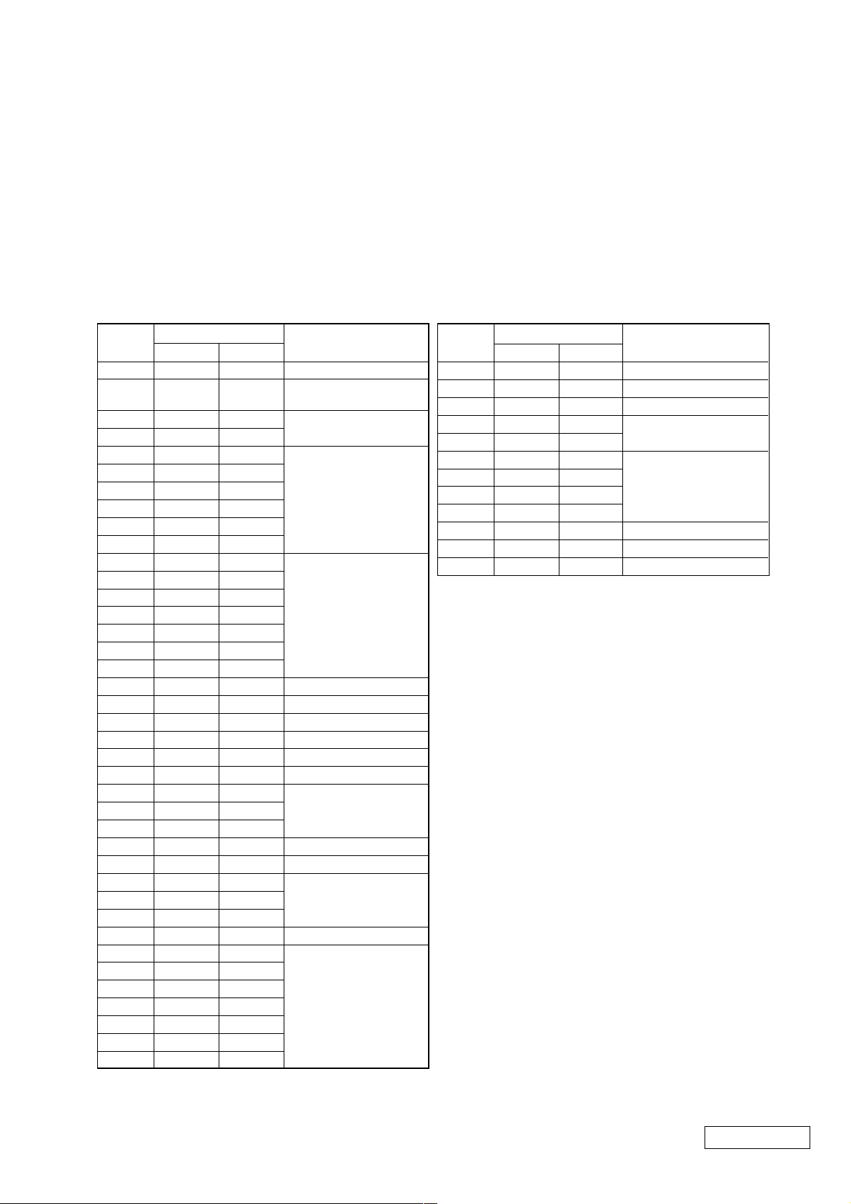
4. Measurement points for adjustment are located at CN803 on
the RG-A01 board. The pin No. and signal name of CN803 is
listed below.
• RG-A01 Board, CN803
Pin No. Signal Name
1GND
2 G OUT
3 B OUT
4 R OUT
5GND
Pin No. Signal Name
6HD
7NC
8NC
9NC
10 NC
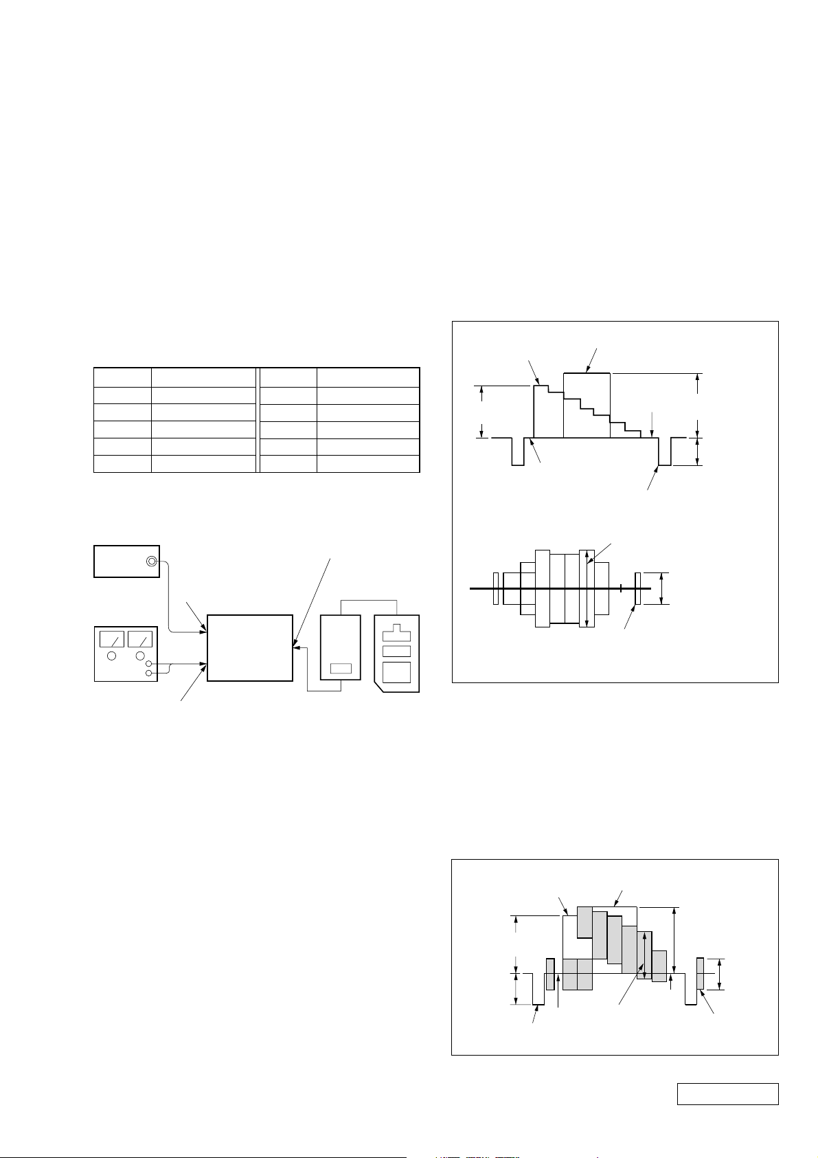
Preparation:
Connect electrical blocks as shown below.
Connector for check (CN305
pattern
generator
S VIDEO IN jack (J401)
or A/V IN jack (J402)
YM-A01 board
YM-A01 board
Adjusting
Remote
Commande
5. Setting up Input Signals
(1) S VIDEO Signal
Connect an oscilloscope to the Y signal pin of the S VIDEO
IN connector, and check that the sync signal of Y signal is
approximately 0.3 V, video amplitude is approximately 0.7
V , and the setup level is 0 V. (If using the VTR with S VIDEO
OUT terminal, check further that the chroma signal and burst
signal do not remain.)
Also, connect an oscilloscope to the chroma signal pin of the
S VIDEO IN connector, and check that the burst signal amplitude of chroma signal is approximately 0.3 V and it is flat,
and moreover, the amplitude ratio of burst signal to “red”
signal is 0.30 : 0.66.
Setup level: Potential difference between black and pedestal
Y signal
White (75%)
approx.
0.53V
Pedestal
Chroma signal
White (100%)
Horizontal
sync signal
Red
Black
approx.
0.7 V
approx.
0.3 V
approx.
0.3 V
Set
DC 9V
Regulated
power supply
Note: In the adjustment where the S VIDEO input is designated, if ad-
justment was made with the VIDEO input. The specification of
this set will not be satisfied. Always follow the designation.
If adjustment was made using the VTR with S VIDEO OUT ter minal as a signal source, the performance of this set depends on that
VTR. Therefore, use the pattern generator with the Y/C separate
output terminals, if possible.
DC IN 9 V jack (J101)
DD-A02 board
Extension cable
(J-6082-291-A)
Burst signal
(to be flat)
Burst amplitude : chroma amplitude = 0.30 : 0.66
Fig. 3-1. Pattern generator’s color bar signals
(2) VIDEO Signal
In adjusting this set, video signals obtained from the pattern
generator are used, and therefore these video output signals
must satisfy the specification. Connect the oscilloscope to
the VIDEO IN terminal, and confirm that the sync signal
amplitude of video signals is approximately 0.3 V, the amplitude of video part is approximately 0.7 V, burst signal amplitude is approximately 0.3 V and flat, and the le v el ratio of
burst signal to “red” signal is 0.30 : 0.66.
White (75%)
approx.
0.53 V
approx.
0.3 V
Pedestal
Horizontal sync signal
White (100%)
Black
Red
approx.
0.7 V
Burst signal
(to be flat)
approx.
0.3 V
Fig. 3-2. Pattern generator’s color bar signals
Confidential
3-1 PLM-A35E (AEP)
[Preparation for Adjustment]
1. Service Jigs
(1) Adjusting remote commander (RM-95-modified)
Note: J-6082-053-B
(2) Extension cable (for remote commander plug converter)
J-6082-291-A
Note: The page will not be changed over, unless the microprocessor in
the adjusting remote commander is a new one (uPD7503-G-C56-
12). In such a case, replace with new microprocessor (8-759-148-
35).
2. Adjusting Remote Commander
For the adjustment, the adjustment data saved in the nonvolatile memory (EEPROM) must be rewritten, and for this purpose the adjusting remote commander is used.
The adjusting remote commander makes two-way communication with the set using a remote control signal line (LANC).
The adjusting remote commander transmits pages, addresses,
and data up/down commands to the set. The set transmits pages,
addresses, and data to the adjusting remote commander.
• Adjustment data writing
The PAUSE button must be pressed to write adjustment
data (D page) to the nonvolatile memory (EEPR OM). (Unless the PAUSE is pressed, new data are not saved in the
nonvolatile memory.)
(4) Select page: 1, address: 00, and set 01 data. Thus, the data
input to page: D is enabled.
(5) After the adjustment finished, select page: 1, address: 00,
and set 00 data. Thus, the data change on page: D is disabled.
(6) After all adjustments finished, turn OFF the main power sup-
ply (9 V) once.
4. Precaution on Use of The Adjusting Remote Commander
Misoperation of the adjusting remote commander could erase
correct data. T o prev ent this, it is recommended to make a note
of data from page: D before adjustment, and also to make a
note of new adjustment data each time the adjustment of one
item is finished.
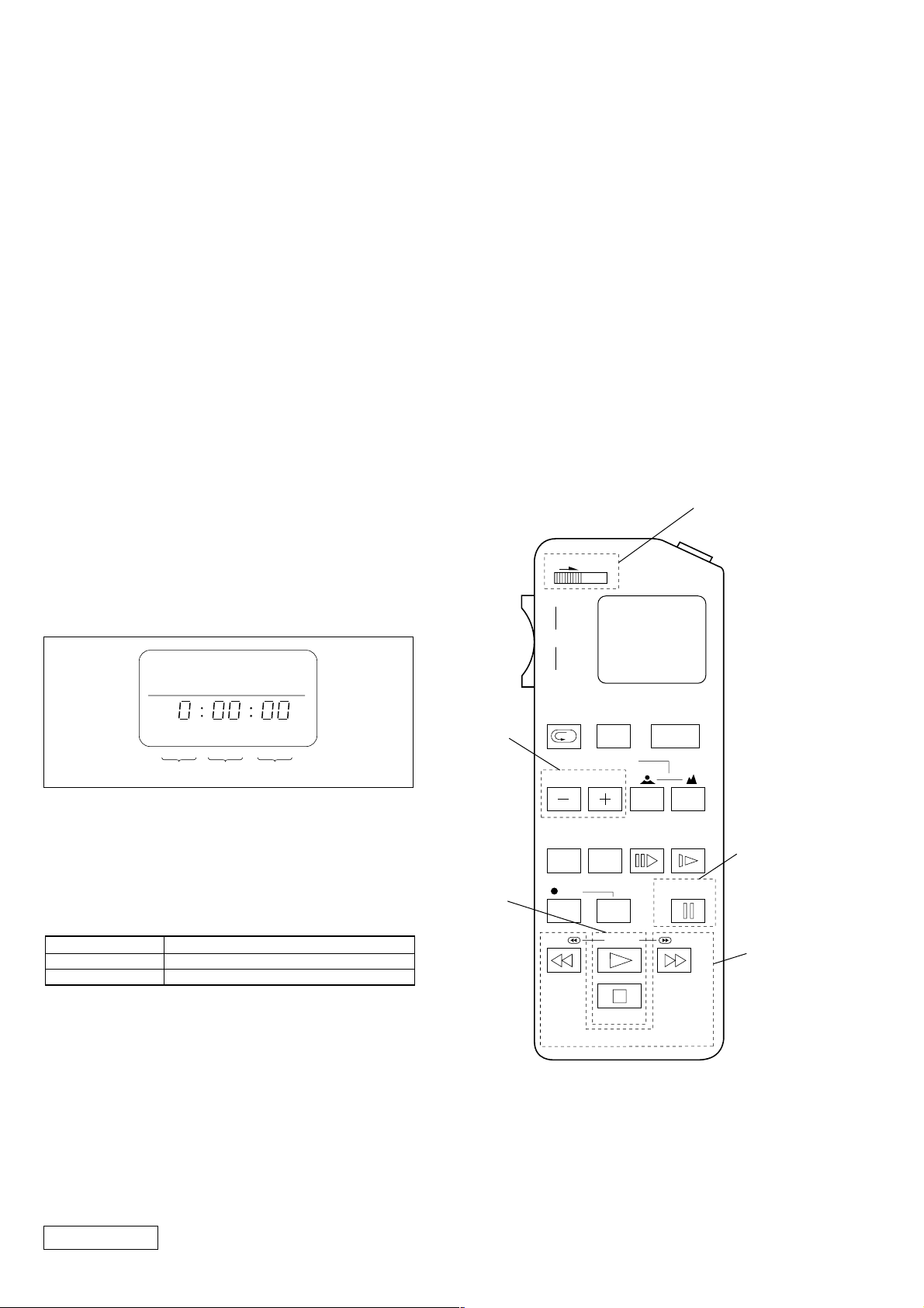
3. How to Use The Adjusting Remote Commander
(1) Connect the adjusting remote commander to the CN305 on
YM-A01 board via extension cable (J-6082-291-A).
At this time, set the switch of extension cable to OFF
(
(OPEN) position
Turn ON the power on the set.
(2) Set the HOLD switch on the adjusting remote commander to
the HOLD (SERVICE) position.
If connection is normal, the LCD display on the adjusting
remote commander will be as shown in Fig.3-3.
Page Data Address
Fig. 3-3
(3) Operate the adjusting remote commander as follows:
• Page change
Press the EDIT SEARCH + button to increase the page.
Press the EDIT SEARCH – button to decrease the page.
There are 16 pages from 0 to F.
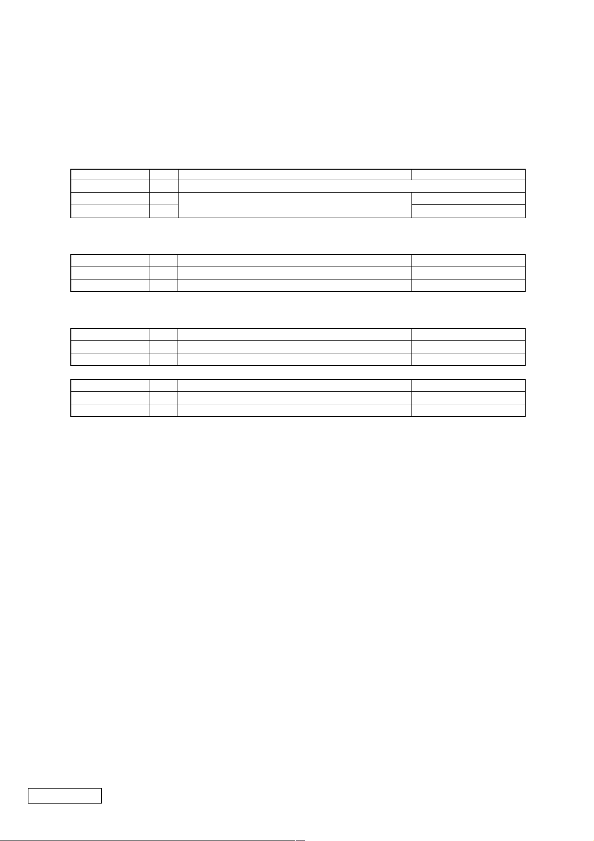
Adjusting Remote Commander RM-95 (J-6082-053-B)
NORMAL(NOR)/SERVICE (ADJ)
mode selection
)
HOLD
WIDE
ZOOM
TELE
REC
Page change
Data change
REVIEW
COUNTER
RESET DISPLAY FRAME SLOW
FOCUS
AUTO/MAN
EDIT SEARCH
REC
START/
STOP
POWER
PAUSE
Data writing
Hexadecimal numbers
LCD display
Decimal conversion
0123456789ABCDEF
23456789 A b c d E F
10
2 3 4 5 6 7 8 9 10 11 12 13 14 15
10
• Address change
Press the FF (M) button to increase the address.
Press the REW (m) button to decrease the address.
There are 256 addresses from 00 to FF.
• Data change (data setting)
Press the PLAY (N) button to increase the data.
Press the STOP (x) button to decrease the data.
There are 256 data from 00 to FF.
Confidential
REW
PB
STOP
FF
RM-95
Address
change
Fig. 3-4
3-2PLM-A35E (AEP)
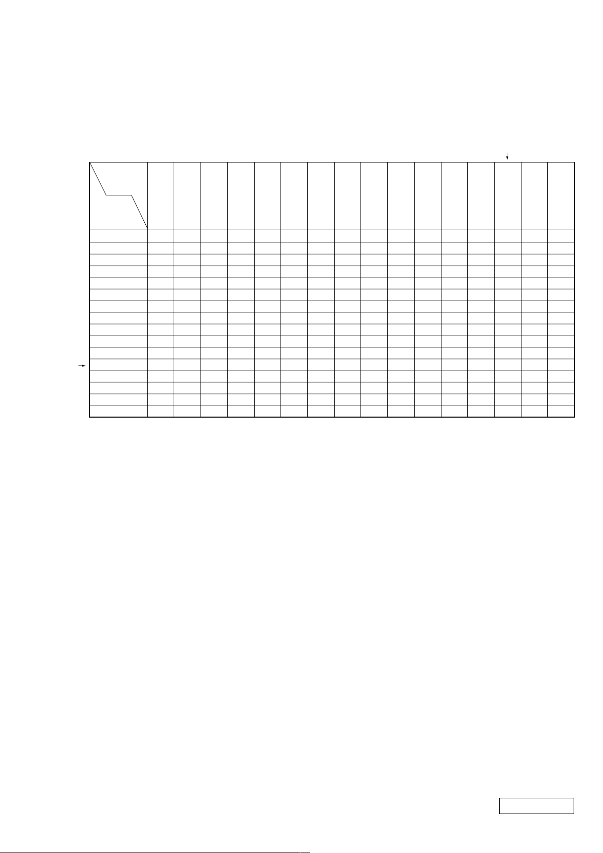
5. Data Processing
Certain adjustment items require the microprocessor data to be read out or the displayed data (hexadecimal numbers) on jigs or
adjusting remote commander to be calculated to get adjustment data. In such a case, convert hexadecimal numbers into decimal
numbers once, then make calculation, and convert its result into hexadecimal number as adjustment data. Table 3-1 shows hexadecimal – decimal number conversion.
Hexadecimal – Decimal number conversion.
Lower digit
of hex.
0123456789
Higher digit
of hex.
123456789
00
1
1
2
3
4
5
6
7
8
9
A (A)
B (b)
C (c)
D (d)
E (E)
F (F)
16 17 18 19 20 21 22 23 24 25
32 33 34 35 36 37 38 39 40 41
48 49 50 51 52 53 54 55 56 57
64 65 66 67 68 69 70 71 72 73
80 81 82 83 84 85 86 87 88 89
96 97 98 99 100 101 102 103 104 105
112 113 114 115 116 117 118 119 120 121
128 129 130 131 132 133 134 135 136 137
144 145 146 147 148 149 150 151 152 153
160 161 162 163 164 165 166 167 168 169
176 177 178 179 180 181 182 183 184 185
192 193 194 195 196 197 198 199 200 201
208 209 210 211 212 213 214 215 216 217
224 225 226 227 228 229 230 231 232 233
240 241 242 243 244 245 246 247 248 249
Table 3-1
2
A
(A) B(b) C(c) D(d) E(E) F(F)
10
26
42
58
74
90
106
122
138
154
170
186
202
218
234
250
11
27
43
59
75
91
107
123
139
155
171
187
203
219
235
251
12
13 14 15
28
29 30 31
44
45 46 47
60
61 62 63
76
77 78 79
92
93 94 95
108
109 110 111
124
125 126 127
140
141 142 143
156
157 158 159
172
173 174 175
188
189 190 191
204
205 206 207
220
221 222 223
236
237 238 239
252
253 254 255
Note: Data in ( ) are displayed on jig or adjusting remote commander.
Example:If display on jig or adjusting remote commander is BD (bd)
As higher digit of hex. number is B (b) and lower digit is D (d), the intersection “189” of 1 and 2 in Table 1 is the target decimal number.
Confidential
3-3 PLM-A35E (AEP)
6. P ower ON Procedure for Adjustment
(1) Connect an extension cable to the adjusting remote commander.
(2) After making sure that the HOLD switch on the adjusting remote commander is not turned on (not at left (NOR) position), supply 9
Vdc to the DC IN (J101).
(With the HOLD switch at HOLD position, the initial operation of the set does not finish, disabling the POWER switc h function)
(3) Turn ON the POWER switch on the set. Confirm that a green LED lights up.
(4) Set the HOLD switch on the adjusting remote commander to the HOLD (right (ADJ)) position.
7. Adjustment Finishing Procedure
Order Page Address Data Description Remarks
1. D 01 – 31 Check if adjusted data are written correctly to the given page and address.
2. 2 00 00
3. 1 00 00 Page D: Write protect
4. Set HOLD switch on adj. remote commander to NOR position.
Set data 00 to given page and address.
Page 2: Reset
8. Check screen skip mode setting
Order Page Address Data Description Remarks
1. 2 00 01 Set data 01 to given page and address. Select RAM address page 1
2. 2 2C 00 Set data 00 to given page and address. No output check screen
Resetting: Turn the POWER switch off.
9. Picture control standard setting (LCD and OPTICS blocks adjustments)
Order Page Address Data Description Remarks
1. 1 00 01 Set data 01 to given page and address. Page D: Cancel protect
2. D 01 41 Set data 41 to given page and address, and press PAUSE. Ope. – Brightness: Center
After LCD and OPTICS blocks adjustments
Order Page Address Data Description Remarks
1. 1 00 01 Set data 01 to given page and address. Page D: Cancel protect
2. D 01 01 Set data 01 to given page and address, and press PAUSE. Ope. – Brightness: Reset center
Confidential
3-4PLM-A35E (AEP)
[Preset Data Writing]
Connection:
(1) Connect the adjusting remote commander to the CN305 on YM-A01 board.
Data Writing Procedure
(1) Set data: 01 to page: 1, address: 00.
(2) Enter the data given in the table below.
Note: To write the data to the EEPROM, press the PAUSE button on the adjusting remote commander each time the data is set.
(3) After writing all data, set data: 00 to page: 1, address: 00.
D Page Adjustment Address and Initial Value
Data in ( ) in Initial set column are different from the data adjusted at the shipment.
Make setting and adjustment only when IC302 (EEPROM) was replaced.
Data in Memo column are fixed value. Always set to this value.
Address
00 –– Not used
01 01 (01)
02 00 00
03 00 00
04 (7D)
05 (78)
06 (75)
07 (67)
08 (60)
09 (08)
0A 4A 4A
0B 03 03
0C 40 40
0D 00 00 Fixed value
0E 40 40
0F 0B 0B
10 00 00
11 74 74 Fixed value
12 (80) Color adj.
13 (A0) G brightness adj.
14 (1A) G contrast adj.
15 (80) R brightness, white adj.
16 (80) B brightness, white adj.
17 A2 A2
18 CE CE Fixed value
19 80 80
1A (80) R contrast adj.
1B (80) B contrast adj.
1C 6D 6D
1D 0A 0A Fixed value
1E 80 80
1F (80) TG PLL adj.
20 03 03
21 00 00
22 00 00
23 00 00 Fixed value
24 00 00
25 00 00
26 0D 0D
Data
Initial set Memo
Remarks
LCD, OPTICS blocks adj.
(Set data: 41 during adj.)
Fixed value
Battery down adj.
Address
27 0D 0D Fixed value
28 (A0) V. COM R adj.
29 (A0) V. COM L adj.
2A (C0)
2B (C0)
2C 00 00
2D 00 00
2E 00 00
2F 00 00
30 (FF) Brightness vol. center adj.
31 23 23 Fixed value
32-FF –– Not used
Data
Initial set Memo
Remarks
BL balance adj.
Fixed value
Confidential
3-5 PLM-A35E (AEP)
LCD BLOCK
• T o adjust the LCD bloc k, connect a pattern generator as sho wn
below. (For details, see page 3-1)
Pattern generator
Set
S VIDEO IN jack (J401)
• Set the picture control standard. (See page 3-4)
• Make the following adjustment in the given order.
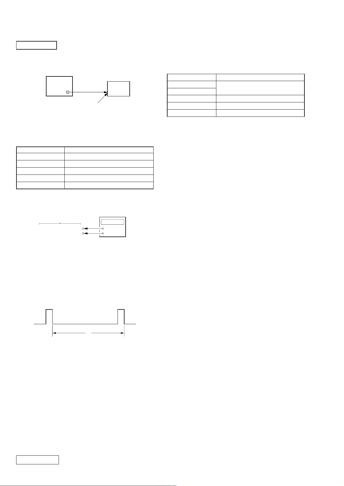
[TG PLL Adjustment]
Condition:
Input signal No signal
Measurement point RG-A01 board CN803 pin 6
Measuring equipment Frequency Counter
Adjustment page D
Adjustment address 1F
Specified value 15.625 kHz ± 20 Hz
Connection:
[Brightness Volume Center Adjustment]
Preparation:
[BRIGHT] control (RV301): Center (click position)
Condition:
Input signal Color bar signal (white 75%)
Measurement point
Measuring equipment
Adjustment page D
Adjustment address 30
Specified value XXh = 80h ± 09h
Adjustment Procedure:
(1) Set data: 01 to page: 2, address: 00.
(2) Read data: XXh on page: 2, address: 2A.
(3) Confirm that the data: XXh satisfies the specified value.
(4) Set (or confirm) data: 01 to page: 1, address: 00.
(Cancel D page protect)
(5) Enter the data: XXh to page: D, address: 30.
(6) Press the PAUSE button to write data.
Displayed data on the adjusting remote
commander
Frequency counter
RG-A01 Board
CN803 pin 6 (HD)
CN803 pin 1 (GND)
+
–
Adjustment Procedure:
(1) Connect a frequency counter to the CN803 pin 6 (HD) and
pin 1 (GND) on RG-A01 board.
(2) Set (or confirm) data: 01 to page: 1, address: 00.
(Cancel D page protect)
(3) On page: D, address: 1F, change data with the PLAY and
STOP buttons and press the PAUSE button to write data so
that the frequency counter reading satisfies the specified
value.
H
Adjustment and Connection Location: RG-A01 board
(see page 3-14)
Confidential
3-6PLM-A35E (AEP)
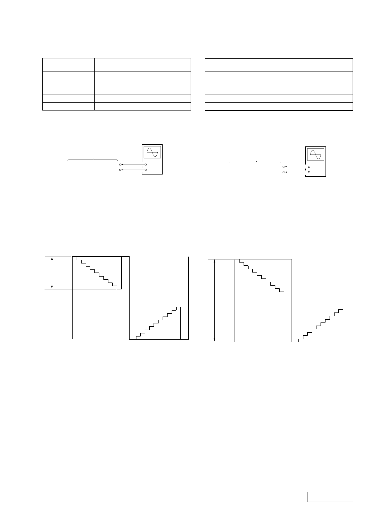
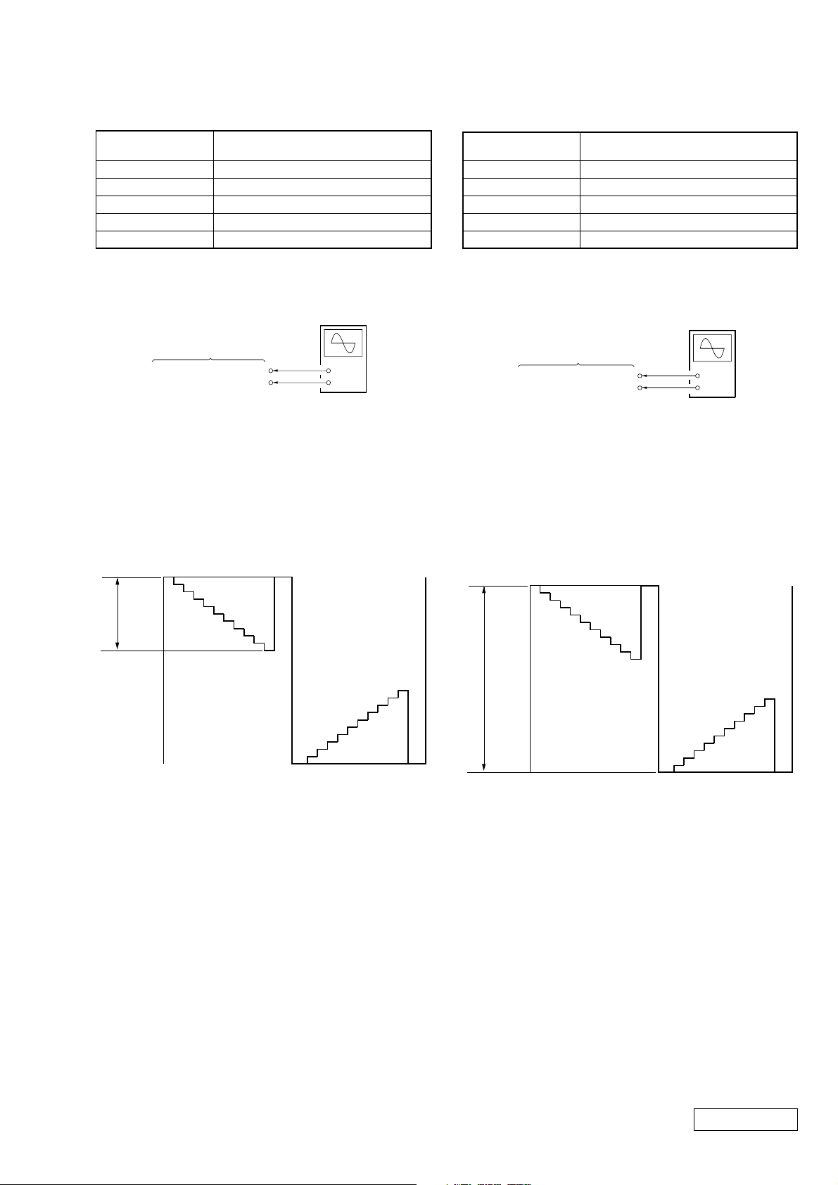
[G Contrast Adjustment]
Condition:
Input signal
Measurement point RG-A01 board CN803 pin 2
Measuring equipment Oscilloscope
Adjustment page D
Adjustment address 14
Specified value 2.4 ± 0.1 Vp-p
10 step signal, 1 Vp-p
(White: 100%)
[G Brightness Adjustment]
Condition:
Input signal
Measurement point RG-A01 board CN803 pin 2
Measuring equipment Oscilloscope
Adjustment page D
Adjustment address 13
Specified value 8.4 ± 0.1 Vp-p
10 step signal, 1 Vp-p
(White: 100%)
Connection:
Oscilloscope
(DC range)
RG-A01 Board
CN803 pin 2 (G OUT)
CN803 pin 1 (GND)
+
–
Adjustment Procedure:
(1) Connect an oscilloscope to the CN803 pin 2 (G OUT) and
pin 1 (GND) on the RG-A01 board.
(2) Set (or confirm) data: 01 to page: 1, address: 00.
(Cancel D page protect)
(3) On page: D, address: 14, change data with the PLAY and
STOP buttons and press the PAUSE button to write data so
that the A level of waveform on the oscilloscope satisfies
the specified value.
Black level
A
White level
Connection:
Oscilloscope
(DC range)
RG-A01 Board
CN803 pin 2 (G OUT)
CN803 pin 1 (GND)
+
–
Adjustment Procedure:
(1) Connect an oscilloscope to the CN803 pin 2 (G OUT) and
pin 1 (GND) on the RG-A01 board.
(2) Set (or confirm) data: 01 to page: 1, address: 00.
(Cancel D page protect)
(3) On page: D, address: 13, change data with the PLAY and
STOP buttons and press the PAUSE button to write data so
that the B level of waveform on the oscilloscope satisfies
the specified value.
Black level
B
Adjustment and Connection Location: RG-A01 board
(see page 3-14)
Black level
Adjustment and Connection Location: RG-A01 board
(see page 3-14)
Confidential
3-7 PLM-A35E (AEP)
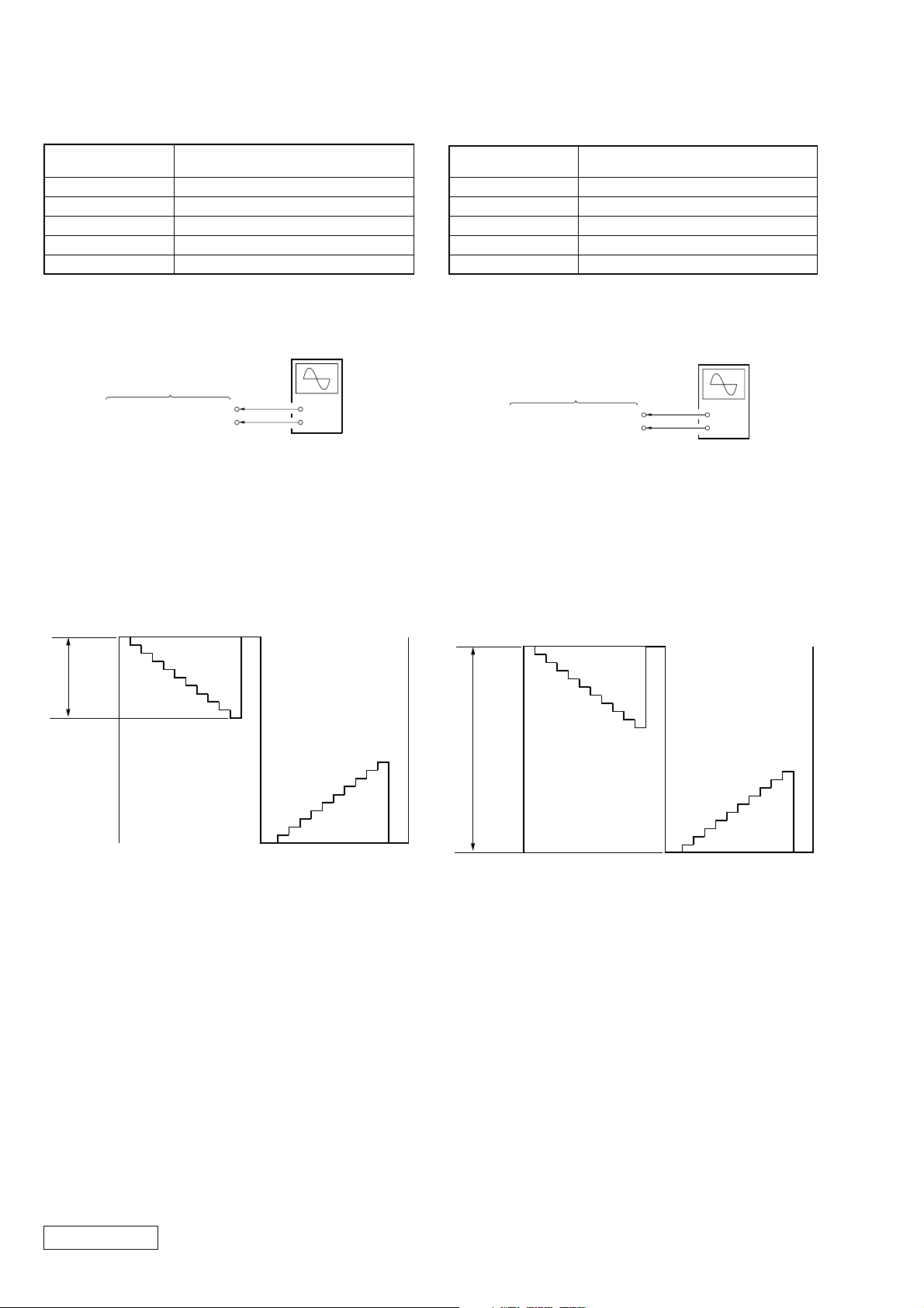
[R Contrast Adjustment]
Condition:
Input signal
Measurement point RG-A01 board CN803 pin 4
Measuring equipment Oscilloscope
Adjustment page D
Adjustment address 1A
Specified value 2.4 ± 0.1 Vp-p
10 step signal, 1 Vp-p
(White: 100%)
[R Brightness Adjustment]
Condition:
Input signal
Measurement point RG-A01 board CN803 pin 4
Measuring equipment Oscilloscope
Adjustment page D
Adjustment address 15
Specified value 8.4 ± 0.1 Vp-p
10 step signal, 1 Vp-p
(White: 100%)
Connection:
Oscilloscope
(DC range)
RG-A01 Board
CN803 pin 4 (R OUT)
CN803 pin 1 (GND)
+
–
Adjustment Procedure:
(1) Connect an oscilloscope to the CN803 pin 4 (R OUT) and
pin 1 (GND) on the RG-A01 board.
(2) Set (or confirm) data: 01 to page: 1, address: 00.
(Cancel D page protect)
(3) On page: D, address: 1A, change data with the PLAY and
STOP buttons and press the PAUSE button to write data so
that the C level of waveform on the oscilloscope satisfies
the specified value.
Black level
C
White level
Connection:
Oscilloscope
(DC range)
RG-A01 Board
CN803 pin 4 (R OUT)
CN803 pin 1 (GND)
+
–
Adjustment Procedure:
(1) Connect an oscilloscope to the CN803 pin 4 (R OUT) and
pin 1 (GND) on the RG-A01 board.
(2) Set (or confirm) data: 01 to page: 1, address: 00.
(Cancel D page protect)
(3) On page: D, address: 15, change data with the PLAY and
STOP buttons and press the PAUSE button to write data so
that the D level of waveform on the oscilloscope satisfies
the specified value.
Black level
D
Adjustment and Connection Location: RG-A01 board
(see page 3-14)
Confidential
Black level
Adjustment and Connection Location: RG-A01 board
(see page 3-14)
3-8PLM-A35E (AEP)
[B Contrast Adjustment]
F
Black level
Black level
Condition:
Input signal
Measurement point RG-A01 board CN803 pin 3
Measuring equipment Oscilloscope
Adjustment page D
Adjustment address 1B
Specified value 2.4 ± 0.1 Vp-p
10 step signal, 1 Vp-p
(White: 100%)
[B Brightness Adjustment]
Condition:
Input signal
Measurement point RG-A01 board CN803 pin 3
Measuring equipment Oscilloscope
Adjustment page D
Adjustment address 16
Specified value 8.4 ± 0.1 Vp-p
10 step signal, 1 Vp-p
(White:100%)
Connection:
Oscilloscope
(DC range)
RG-A01 Board
CN803 pin 3 (B OUT)
CN803 pin 1 (GND)
+
–
Adjustment Procedure:
(1) Connect an oscilloscope to the CN803 pin 3 (B OUT) and
pin 1 (GND) on the RG-A01 board.
(2) Set (or confirm) data: 01 to page: 1, address: 00.
(Cancel D page protect)
(3) On page: D, address: 1B, change data with the PLAY and
STOP buttons and press the PAUSE button to write data so
that the E level of waveform on the oscilloscope satisfies
the specified value.
Black level
E
White level
Connection:
Oscilloscope
(DC range)
RG-A01 Board
CN803 pin 3 (B OUT)
CN803 pin 1 (GND)
+
–
Adjustment Procedure:
(1) Connect an oscilloscope to the CN803 pin 3 (B OUT) and
pin 1 (GND) on the RG-A01 board.
(2) Set (or confirm) data: 01 to page: 1, address: 00.
(Cancel D page protect)
(3) On page: D, address: 16, change data with the PLAY and
STOP buttons and press the PAUSE button to write data so
that the F level of waveform on the oscilloscope satisfies
the specified value.
Adjustment and Connection Location: RG-A01 board
(see page 3-14)
Adjustment and Connection Location: RG-A01 board
(see page 3-14)
Confidential
3-9 PLM-A35E (AEP)
 Loading...