

Page 1

2-345-277-01(1)
LCD Multi
Function Display
MFM-HT75W
MFM-HT95
© 2004 Sony Corporation
Page 2
Owner’s Record
The model and serial numbers are located at the rear of the unit.
Record these numbers in the spaces provided below. Refer to them
whenever you call upon your dealer regarding this product.
Model No.
Serial No.
WARNING
To prevent fire or shock hazard, do not expose the
unit to rain or moisture.
Dangerously high voltages are present inside the
unit. Do not open the cabinet. Refer servicing to
qualified personnel only.
FCC Notice
This equipment has been tested and found to comply with the limits
for a Class B digital device, pursuant to Part 15 of the FCC Rules.
These limits are designed to provide reasonable protection against
harmful interference in a residential installation. This equipment
generates, uses, and can radiate radio frequency energy and, if not
installed and used in accordance with the instructions, may cause
harmful interference to radio communications. However, there is no
guarantee that interference will not occur in a particular installation.
If this equipment does cause harmful interference to radio or
television reception, which can be determined by turning the
equipment off and on, the user is encouraged to try to correct the
interference by one or more of the following measures:
– Reorient or relocate the receiving antenna.
– Increase the separation between the equipment and receiver.
– Connect the equipment into an outlet on a circuit different from
that to which the receiver is connected.
– Consult the dealer or an experienced radio/TV technician for help.
You are cautioned that any changes or modifications not expressly
approved in this manual could void your authority to operate this
equipment.
IMPORTANTE
Para prevenir cualquier mal funcionamiento y evitar daños, por
favor, lea detalladamente este manual de instrucciones antes
de conectar y operar este equipo.
If you have any questions about this product, you may call;
Sony Customer Information Services Center
1-800-222-7669 or http://www.sony.com/
Declaration of Conformity
Trade Name: SONY
Model: MFM-HT75W/HT95
Responsible Party: Sony Electronics Inc.
Address: 16450 W. Bernardo Dr,
Telephone Number: 858-942-2230
This device complies with part 15 of the FCC rules. Operation is
subject to the following two conditions: (1) This device may not
cause harmful interference, and (2) this device must accept any
interference received, including interference that may cause
undesired operation.
San Diego, CA 92127 U.S.A.
NOTICE
This notice is applicable for USA/Canada only.
If shipped to USA/Canada, install only a UL LISTED/CSA
LABELLED power supply cord meeting the following
specifications:
SPECIFICATIONS
Plug Type Nema-Plug 5-15p
Cord Type SVT or SJT, minimum 3 × 18 AWG
Length Maximum 15 feet
Rating Minimum 7 A, 125 V
NOTICE
Cette notice s’applique aux Etats-Unis et au Canada
uniquement.
Si cet appareil est exporté aux Etats-Unis ou au Canada, utiliser
le cordon d’alimentation portant la mention UL LISTED/CSA
LABELLED et remplissant les conditions suivantes:
SPECIFICATIONS
Type de fiche Fiche Nema 5-15 broches
Cordon Type SVT ou SJT, minimum 3 × 18 AWG
Longueur Maximum 15 pieds
Tension Minimum 7 A, 125 V
ENERGY STAR Partner, Sony
As an
Corporation has determined that this
product meets the
guidelines for energy efficiency.
ENERGY STAR
Important Safety Instructions
1) Read these instructions.
2) Keep these instructions.
3) Heed all warnings.
4) Follow all instructions.
5) Do not use this apparatus near water.
6) Clean only with dry cloth.
7) Do not block any ventilation openings. Install in accordance
with the manufacturer’s instructions.
8) Do not install near any heat sources such as radiators, heat
registers, stoves, or other apparatus (including amplifiers) that
produce heat.
9) Do not defeat the safety purpose of the polarized or groundingtype plug. A polarized plug has two blades with one wider than
the other. A grounding type plug has two blades and a third
grounding prong. The wide blade or the third prong are
provided for your safety. If the provided plug does not fit into
your outlet, consult an electrician for replacement of the
obsolete outlet.
10) Protect the power cord from being walked on or pinched
particularly at plugs, convenience receptacles, and the point
where they exit from the apparatus.
11) Only use attachments/accessories specified by the
manufacturer.
12) Use only with the cart, stand, tripod, bracket, or table specified
by the manufacturer, or sold with the apparatus. When a cart is
used, use caution when moving the cart/apparatus
combination to avoid injury from tip-over.
13) Unplug this apparatus during lightning storms or when unused
for long periods of time.
14) Refer all servicing to qualified service personnel. Servicing is
required when the apparatus has been damaged in any way,
such as power-supply cord or plug is damaged, liquid has been
spilled or objects have fallen into the apparatus, the apparatus
has been exposed to rain or moisture, does not operate
normally, or has been dropped.
2
Page 3
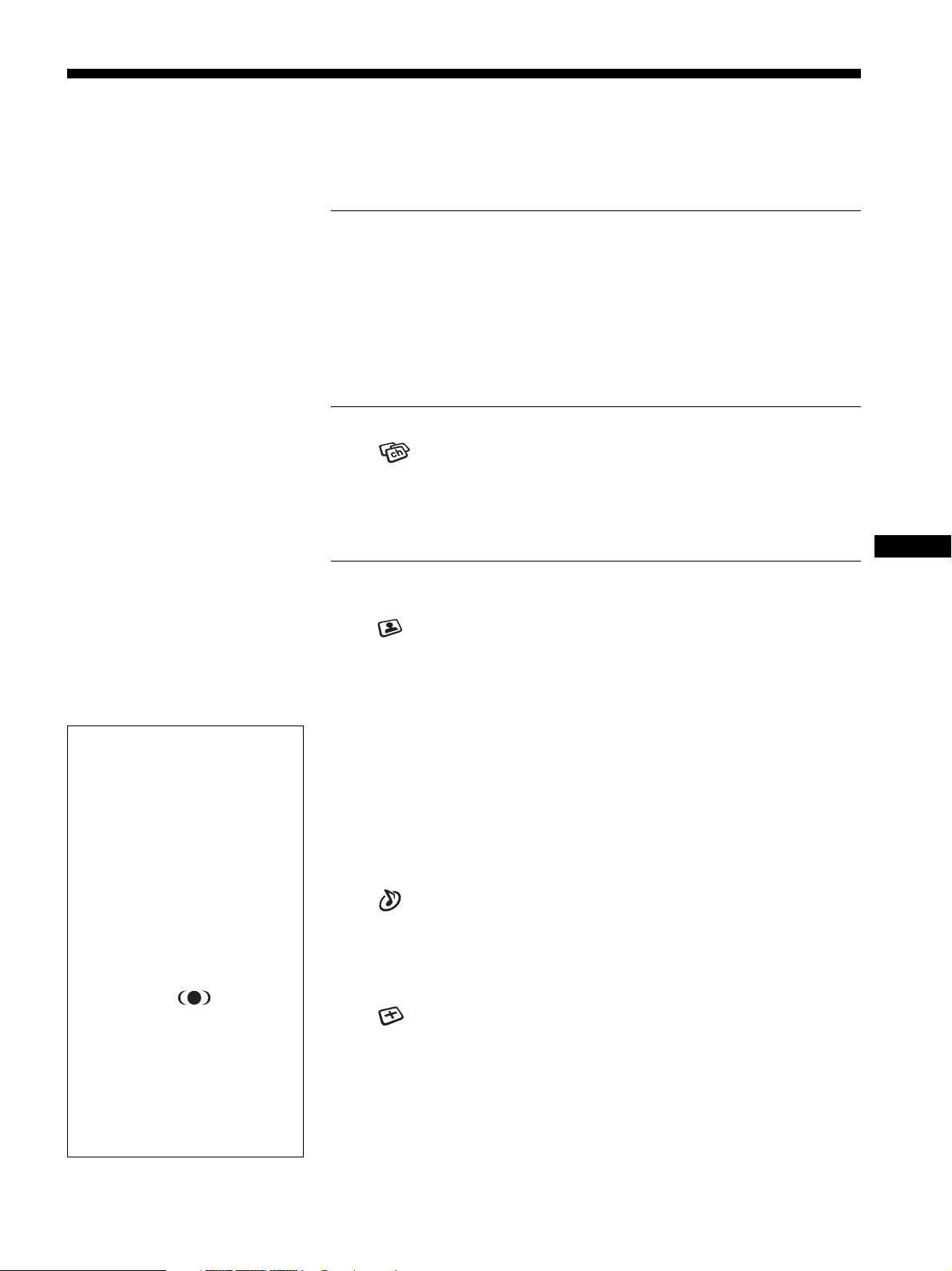
Table of Contents
Precautions . . . . . . . . . . . . . . . . . . . . . . . . . . . . . . . . . . . . . . . . . . . 5
Identifying parts and controls . . . . . . . . . . . . . . . . . . . . . . . . . . . . . . 6
Setup . . . . . . . . . . . . . . . . . . . . . . . . . . . . . . . . . . . . . . . . .9
Setup 1: Open the stand . . . . . . . . . . . . . . . . . . . . . . . . . . . . . . . . . 9
Setup 2: Connect the cables . . . . . . . . . . . . . . . . . . . . . . . . . . . . . . 9
Setup 3: Connect the power cord . . . . . . . . . . . . . . . . . . . . . . . . . 12
Setup 4: Replace the connector cover . . . . . . . . . . . . . . . . . . . . . 12
Setup 5: Turn on the display and other equipment . . . . . . . . . . . . 12
Setup 6: Adjust the tilt . . . . . . . . . . . . . . . . . . . . . . . . . . . . . . . . . . 13
Setup 7: Insert batteries into the remote control . . . . . . . . . . . . . . 13
Watching the TV . . . . . . . . . . . . . . . . . . . . . . . . . . . . . . .14
Setting the TV channels . . . . . . . . . . . . . . . . . . . . . . . . . . . . 14
Changing the TV channel . . . . . . . . . . . . . . . . . . . . . . . . . . . . . . . 14
Skipping unnecessary channels . . . . . . . . . . . . . . . . . . . . . . . . . . 14
Choosing between cable and UHF/VHF . . . . . . . . . . . . . . . . . . . . 14
Using other features . . . . . . . . . . . . . . . . . . . . . . . . . . . . . . . . . . . 15
US
• Macintosh is a trademark licensed to
Apple Computer, Inc., registered in the
U.S.A. and other countries.
• Windows
Microsoft Corporation in the United
States and other countries.
• IBM PC/AT and VGA are registered
trademarks of IBM Corporation of the
U.S.A.
• VESA and DDC
Video Electronics Standards
Association.
ENERGY STAR is a U.S. registered
•
mark.
• Adobe and Acrobat are trademarks of
Adobe Systems Incorporated.
• WOW, SRS and symbol are
trademarks of SRS Labs, Inc.
• WOW technology is incorporated under
license from SRS Labs, Inc.
• All other product names mentioned
herein may be the trademarks or
registered trademarks of their respective
companies.
•Furthermore, “” and “” are not
mentioned in each case in this manual.
is registered trademark of
are trademarks of the
http://www.sony.net/
Customizing Your Display . . . . . . . . . . . . . . . . . . . . . . .15
Navigating the menu . . . . . . . . . . . . . . . . . . . . . . . . . . . . . . . . . . . 15
Picture menu . . . . . . . . . . . . . . . . . . . . . . . . . . . . . . . . . . . . . 17
Selecting the Picture Mode for PC 1/PC 2 . . . . . . . . . . . . . . . . 17
Selecting the Picture Mode for TV/VIDEO 1/VIDEO 2 . . . . . . . 17
Adjusting “Backlight” . . . . . . . . . . . . . . . . . . . . . . . . . . . . . . . . . 18
Adjusting “Contrast” (“Picture”) . . . . . . . . . . . . . . . . . . . . . . . . . 18
Adjusting “Brightness” . . . . . . . . . . . . . . . . . . . . . . . . . . . . . . . . 18
Adjusting “Color” (for TV/VIDEO 1/VIDEO 2 only) . . . . . . . . . . 18
Adjusting “Hue” (for TV/VIDEO 2 only) . . . . . . . . . . . . . . . . . . . 18
Adjusting “Sharpness”(for TV/VIDEO 1/VIDEO 2 only) . . . . . . 18
Adjusting “Color Temp.” (for PC 1/PC 2 only) . . . . . . . . . . . . . . 19
Adjusting “Gamma” (for PC 1/PC 2 only) . . . . . . . . . . . . . . . . . 19
Resetting Picture Mode to the default . . . . . . . . . . . . . . . . . . . . 20
Setting “NR” (for TV/VIDEO 1/VIDEO 2 only) . . . . . . . . . . . . . . 20
Setting “Dynamic Picture” (for TV/VIDEO 1/VIDEO 2 only) . . . 20
Audio menu . . . . . . . . . . . . . . . . . . . . . . . . . . . . . . . . . . . . . . . 21
Setting “Surround” . . . . . . . . . . . . . . . . . . . . . . . . . . . . . . . . . . 21
Adjusting “Treble,” “Bass,” and “Balance” . . . . . . . . . . . . . . . . . 21
Setting “Auto Volume” (for TV/VIDEO 1/VIDEO 2 only) . . . . . . 21
Setting “MTS” (for TV only) . . . . . . . . . . . . . . . . . . . . . . . . . . . . 22
Resetting all audio settings to the default . . . . . . . . . . . . . . . . . 22
Screen menu . . . . . . . . . . . . . . . . . . . . . . . . . . . . . . . . . . . . . 22
Setting “Zoom” . . . . . . . . . . . . . . . . . . . . . . . . . . . . . . . . . . . . . 22
Automatic picture quality adjustment function (for PC 2 only) . 23
Making further automatic adjustments to the picture quality
for the current input signal (Auto Adjust) (for PC 2 only) . . . . . 23
Adjusting the picture’s sharpness manually (Phase/Pitch)
(for PC 2 only) . . . . . . . . . . . . . . . . . . . . . . . . . . . . . . . . . . . . . . 24
Adjusting the picture’s position manually
(H Center /V Center) (for PC 2 only) . . . . . . . . . . . . . . . . . . . . . 24
3
Page 4

Parent menu . . . . . . . . . . . . . . . . . . . . . . . . . . . . . . . . . . . . . 25
Activating the Parental Control feature . . . . . . . . . . . . . . . . . . 25
Selecting a Custom Rating . . . . . . . . . . . . . . . . . . . . . . . . . . . 26
What the Ratings Mean . . . . . . . . . . . . . . . . . . . . . . . . . . . . . . 28
Option menu . . . . . . . . . . . . . . . . . . . . . . . . . . . . . . . . . . . . . . 30
Setting “PIP” (Picture In Picture) (for PC 1/PC 2 only) . . . . . . 30
Setting “Caption Vision” (for TV/VIDEO 1/VIDEO 2 only) . . . . 32
Setting “Input Sensing” (for PC 1/PC 2 only) . . . . . . . . . . . . . . 32
Setting “Language” . . . . . . . . . . . . . . . . . . . . . . . . . . . . . . . . . 32
Setting “Menu Position” . . . . . . . . . . . . . . . . . . . . . . . . . . . . . . 32
Setting “Menu Lock” . . . . . . . . . . . . . . . . . . . . . . . . . . . . . . . . 33
Setting “Demo Mode” . . . . . . . . . . . . . . . . . . . . . . . . . . . . . . . 33
Resetting to the default setting . . . . . . . . . . . . . . . . . . . . . . . . 33
Technical Features . . . . . . . . . . . . . . . . . . . . . . . . . . . . .34
Controlling the volume . . . . . . . . . . . . . . . . . . . . . . . . . . . . . . . . . 34
Power saving function . . . . . . . . . . . . . . . . . . . . . . . . . . . . . . . . . . 34
Setting the Picture Mode . . . . . . . . . . . . . . . . . . . . . . . . . . . . . . . 35
Automatic brightness adjustment function (light sensor) . . . . . . . 35
Automatic picture quality adjustment function (for PC 2 only) . . . 35
Turning off the display automatically
(for TV/VIDEO 1/VIDEO 2 only) . . . . . . . . . . . . . . . . . . . . . . . . . . 36
Troubleshooting . . . . . . . . . . . . . . . . . . . . . . . . . . . . . . .36
On-screen messages . . . . . . . . . . . . . . . . . . . . . . . . . . . . . . . . . . 36
Trouble symptoms and remedies . . . . . . . . . . . . . . . . . . . . . . . . . 38
Specifications . . . . . . . . . . . . . . . . . . . . . . . . . . . . . . . . .41
4
Page 5
Precautions
Warning on power connections
• Use the supplied power cord. If you use a different power cord,
be sure that it is compatible with your local power supply.
For the customers in the U.S.A.
If you do not use the appropriate cord, this display will not
conform to mandatory FCC standards.
For the customers in the UK
If you use the display in the UK, be sure to use the appropriate
UK power cord.
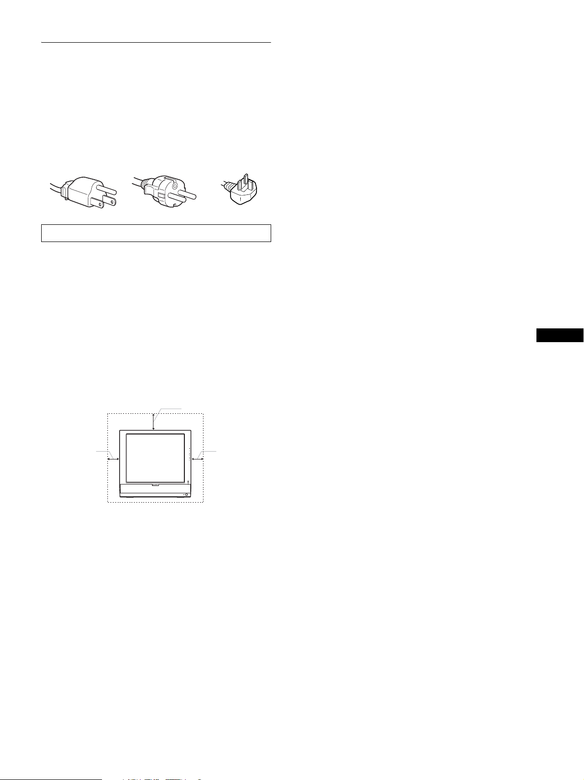
Example of plug types
for 100 to 120 V AC for 200 to 240 V AC for 240 V AC only
The equipment should be installed near an easily accessible outlet.
Installation
Do not install or leave the display:
• In places subject to extreme temperatures, for example near a
radiator, heating vent, or in direct sunlight. Subjecting the
display to extreme temperatures, such as in an automobile
parked in direct sunlight or near a heating vent, could cause
deformations of the casing or malfunctions.
• In places subject to mechanical vibration or shock.
• The ventilation should not be impeded by covering the
ventilation openings with items, such as newspapers, tablecloths, curtains, etc.
• Leave some space around the unit. Otherwise, adequate aircirculation may be blocked causing overheating and cause fire
or damage the unit.
20 cm
10 cm
• Near any equipment that generates a strong magnetic field,
such as a TV or various other household appliances.
• In places subject to inordinate amounts of dust, dirt, or sand, for
example near an open window or an outdoor exit. If setting up
temporarily in an outdoor environment, be sure to take
adequate precautions against airborne dust and dirt. Otherwise
irreparable malfunctions could occur.
• To reduce the risk of fire or electric shock, do not expose this
Apparatus to rain or moisture.
• Apparatus shall not be exposed to dripping or splashing and no
objects filled with liquids, such as vases, shall be placed on the
apparatus.
• To prevent fire, keep inflammable objects or naked lights (e.g.
candles) away from the unit.
• Do not place the unit near or over a radiator or heat register, or
where it is exposed to direct sunlight.
Handling the LCD screen
• Do not leave the LCD screen facing the sun as it can damage
the LCD screen. Take care when you place the display by a
window.
10 cm
• Do not push on or scratch the LCD screen. Do not place a heavy
object on the LCD screen. This may cause the screen to lose
uniformity or cause LCD panel malfunctions.
• If the display is used in a cold place, a residual image may
appear on the screen. This is not a malfunction. The screen
returns to normal as the temperature rises to a normal operating
level.
• If a still picture is displayed for a long time, a residual image
may appear for a while. The residual image will eventually
disappear.
• The LCD panel becomes warm during operation. This is not a
malfunction.
About the built-in stereo speakers
Be sure to keep magnetic recording equipment, tapes, and floppy
discs away from the speaker’s opening as the speakers generate a
magnetic field. This magnetic field may affect data stored on
magnetic tapes and discs.
Note on the LCD (Liquid Crystal Display)
Please note that the LCD screen is made with high-precision
technology. However, black points or bright points of light (red,
blue, or green) may appear constantly on the LCD screen, and
irregular colored stripes or brightness may appear on the LCD
screen. This is not malfunction.
(Effective dots: more than 99.99%)
Maintenance
• Be sure to unplug the power cord from the power outlet before
cleaning your display.
• Clean the LCD screen with a soft cloth. If you use a glass
cleaning liquid, do not use any type of cleaner containing an
anti-static solution or similar additive as this may scratch the
LCD screen’s coating.
• Clean the cabinet, panel, and controls with a soft cloth lightly
moistened with a mild detergent solution. Do not use any type
of abrasive pad, scouring powder, or solvent, such as alcohol or
benzine.
• Do not rub, touch, or tap the surface of the screen with sharp or
abrasive items such as a ballpoint pen or screwdriver. This type
of contact may result in a scratched picture tube.
• Note that material deterioration or LCD screen coating
degradation may occur if the display is exposed to volatile
solvents such as insecticide, or if prolonged contact is
maintained with rubber or vinyl materials.
Transportation
• Disconnect all cables from the display, and grasp both side of
the LCD display firmly taking care not to scratch the screen
when transporting. If you drop the display, you may be injured
or the display may be damaged.
• When you transport this display for repair or shipment, use the
original carton and packing materials.
Disposal of the display
• Do not dispose of this display with general
household waste.
• The fluorescent tube used in this display contains
mercury. Disposal of this display must be carried out
in accordance to the regulations of your local
sanitation authority.
Disposal of used batteries
To preserve our environment, dispose the used batteries
according to your local laws or regulations.
US
5
Page 6
For customers in the United States
This product contains mercury. Disposal of this product may be
regulated if sold in the United States. For disposal or recycling
information, please contact your local authorities or the
Electronics Industries Alliance
(http://www.eiae.org).
Installation on a wall or a mounting arm
If you intend to install the display on a wall or a mounting arm, be
sure to consult qualified personnel.
Identifying parts and controls
See the pages in parentheses for further details.
Front of the LCD display
qd
A Remote control sensor
This sensor receives a signal from the remote control.
Be sure not to cover the sensor with papers, etc.
B Light sensor (page 35)
This sensor measures the brightness of the surrounding area.
Be sure not to cover the sensor with papers, etc.
C 1 (power) switch (page 12)
Press to turn the display on or off.
D 1 (power) indicator (pages 12, 34)
The power indicator lights up in green when the display is
turned on, and lights up in orange when the display is in the
power saving mode. Also, the power indicator lights up in red
when the display is in the standby mode or the Sleep timer is
activated.
5
Side view of the LCD display
1
2
43
6
7
E Stereo speakers (page 34)
These speakers output the audio signals as sound.
F MENU button (page 15)
Press to turn the menu screen on and off.
G CH+/– buttons (page 14)
Press to change the TV channel.
H M/m and VOL+/– (volume control) buttons
(pages 15, 34)
Use to select the menu items and to make adjustments, and
also display the “Volume” adjustment bar to control the
volume.
I (input select)/OK button (page 12, 15)
This button functions in two ways.
As the button, this button switches the input signal
between PC 1, PC 2, TV, VIDEO 1, and VIDEO 2 when two
computers and two pieces of video equipment are connected.
As the OK button, this button activates the selected menu item
or adjustments made using the M/m buttons 8.
J (PinP) button (page 30)
Press to switch the “PIP” (Picture In Picture) setting.
Each time you press this button, the PIP setting changes as
follows.
PIP On t PIP Off t PIP On...
8
K (Picture Mode) button (page 35)
Press to switch the Picture Mode.
9
0
L Headphones jack (page 34)
This jack outputs audio signals to the headphones.
qa
qs
6
Page 7
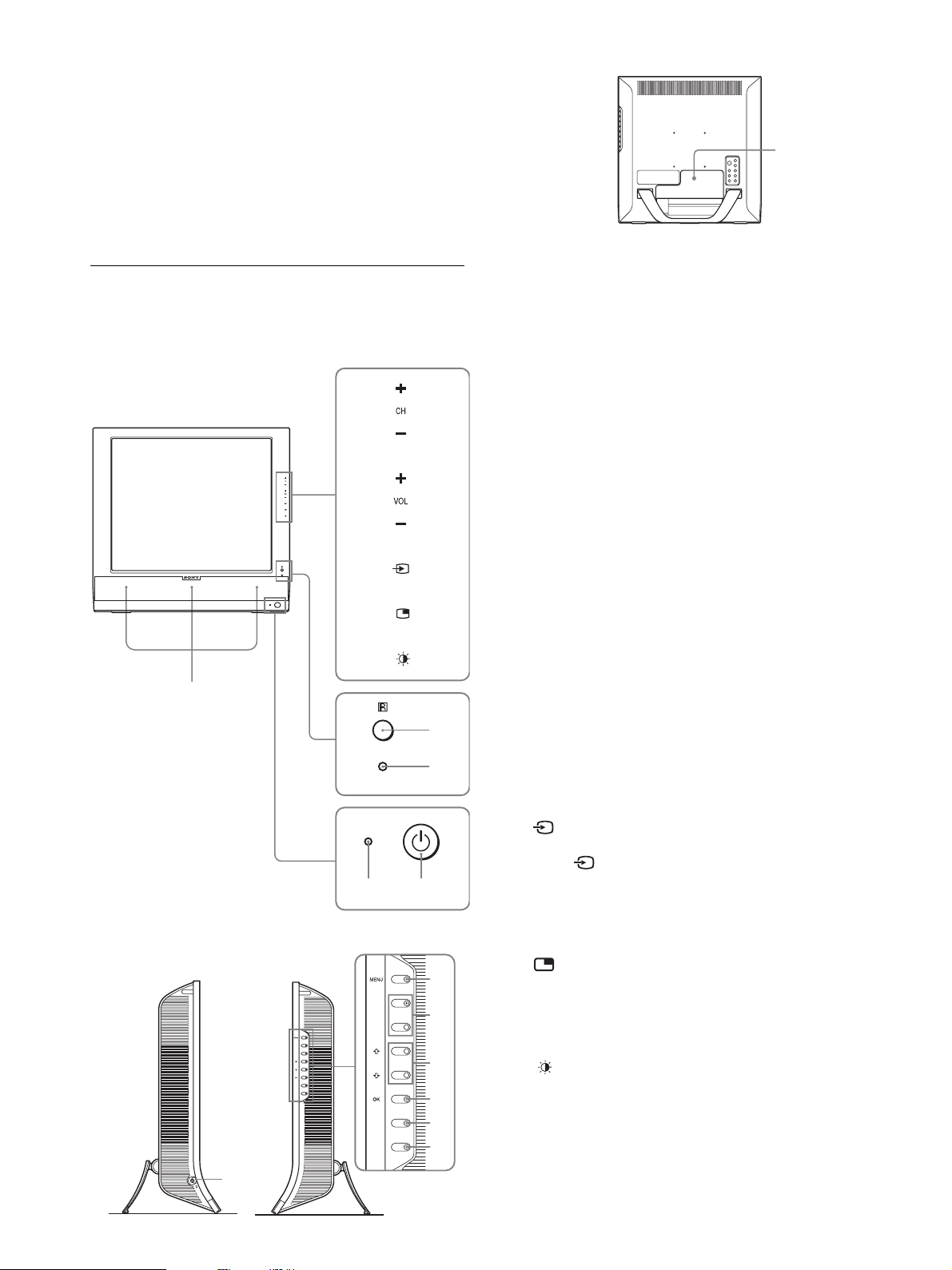
M Connector cover (page 9)
Remove this cover when you connect cables or cords.
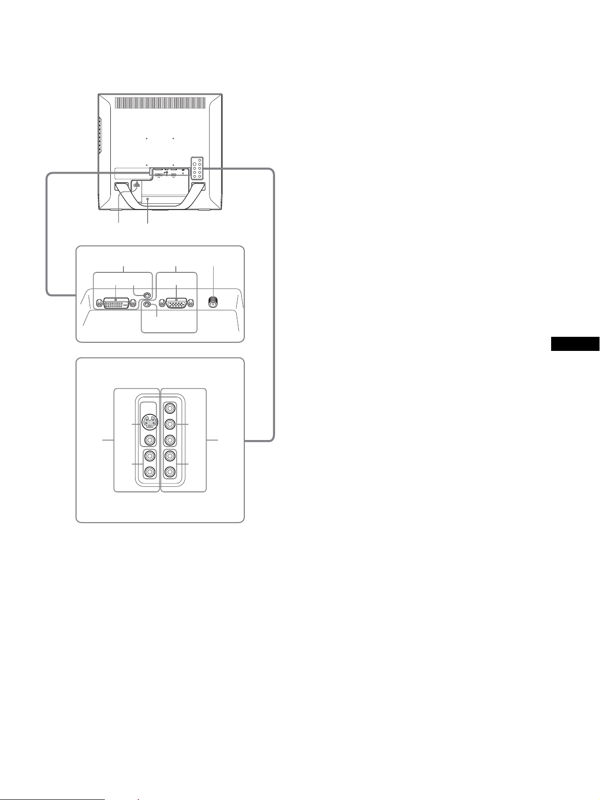
Rear of the LCD display
qf
qh
qg
qj
qk
12 1
PC 1 PC 2 VHF/UHF
1
2
2
VIDEO 2 IN VIDEO 1 IN
1
2
P PC 1 connectors
1 DVI-D input connector (digital RGB) for PC 1
(page 9)
This connector inputs digital RGB video signals that
comply with DVI Rev.1.0.
2 Audio input jack for PC 1 (page 9)
This jack inputs audio signals when connected to the
audio output jack of a computer or other equipment
connected to PC 1.
Q PC 2 connectors
1 HD15 input connector (analog RGB) for PC 2
(page 9)
This connector inputs analog RGB video signals (0.700
Vp-p, positive) and sync signals.
2 Audio input jack for PC 2 (page 9)
This jack inputs audio signals when connected to the
audio output jack of a computer or other equipment
connected to PC 2.
R VHF/UHF jack (page 11)
This jack inputs a signal from an antenna.
S VIDEO 2 jacks
1 Composite/S video input jacks for VIDEO 2
(page 11)
These jacks input composite video or S video signals.
When you connect video equipment to both composite
video input and S video input jacks, the signal from the S
video jack is displayed.
2 Audio input jacks for VIDEO 2 (page 11)
These jacks input audio signals when connected to the
audio output jacks of a VCR or other equipment
connected to VIDEO 2.
w;ql
T VIDEO 1 jacks
1 Y/PB/PR Component Video input jacks for
VIDEO 1 (page 10)
These jacks input Y/P
C
, Y/B-Y/R-Y, or Y/PB/PR).
B/CR
2 Audio input jacks for VIDEO 1 (page 10)
These jacks input audio signals when connected to the
audio output jacks of a DVD player or other equipment
connected to VIDEO 1.
Component Video signals (Y/
B/PR
US
N AC IN connector (page 12)
This connector connects the power cord (supplied).
O Security Lock Hole
The security lock hole should be used with the Kensington
Micro Saver Security System.
Micro Saver Security System is a trademark of Kensington.
7
Page 8
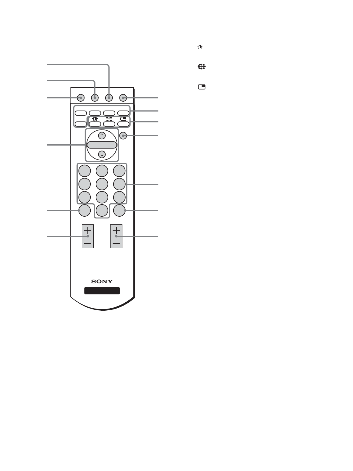
Remote control
8
9
0
qa
MUTING DISPLAY SLEEP 1
PC1 PC2 VIDEO1 VIDEO2
TV
MENU
OK
1
2
3
4
TV (page 14): Press to select the TV input.
C Feature buttons
(Picture Mode) (page 35):
Press repeatedly to step through the
Picture Mode.
(Zoom) (page 22):
Press repeatedly to step through the
“Zoom” settings.
(PinP) (page 30):
Press repeatedly to step through the
“PIP” settings.
D MENU button (page 15)
Press to turn the menu screen on and off.
E 0-9 buttons (page 14)
Use these buttons to input numbers.
F ENT (enter) button (page 14)
Press to confirm the numbers you input using the 0-9 buttons.
123
456
789
qs
qd
A 1 (power) switch (page 12)
Press to turn the display on or off.
B Input select buttons
PC 1 (page 9): Press to select a signal input through
PC 2 (page 9): Press to select a signal input through
VIDEO 1 (page 10):Press to select a signal input through
VIDEO 2 (page 11):Press to select a signal input through
JUMP
VOL CH
DISPLAY
the PC 1 connectors (DVI-D) on the
rear.
the PC 2 connectors (HD15) on the
rear.
the VIDEO 1 jacks (Y/PB/PR
Component) on the rear.
the VIDEO 2 jacks (composite/S
video) on the rear.
ENT
0
5
6
7
G CH +/– buttons (page 14)
Press to change the TV channel.
H SLEEP button (page 36)
Press repeatedly to set the display to turn off automatically
after a specified period of time. If you use this function and
set the Sleep timer, the 1 (power) indicator lights up in red.
I DISPLAY button (page 15)
Press once to display the current channel number. The
channel number displayed will remain until you press this
button again.
J MUTING button (page 15)
Press to turn the sound off. Press again or press the VOL +
button to restore the sound.
K M/m and OK buttons (page 15)
Use the M/m buttons to select menu items and make
adjustments.
Press the OK button to activate the selected menu item and
adjustments made using the M/m buttons.
L JUMP button (page 15)
Press to switch the TV channel between the current one and
the last one that was selected using the 0-9 buttons.
M VOL +/– buttons (page 34)
Press to adjust the sound volume.
8
Page 9
Setup
Before using your display, check that the following items are
included in your carton:
•LCD display
• Remote control
• Size AAA batteries (2)
• Power cord
• HD15-HD15 video signal cable (analog RGB)
• DVI-D video signal cable (digital RGB)
• Audio cord (stereo miniplug)
• 75-ohm coaxial cable
• CD-ROM (utility software for Windows/Macintosh, Operating
Instructions, etc.)
• Warranty card
• Quick Setup Guide
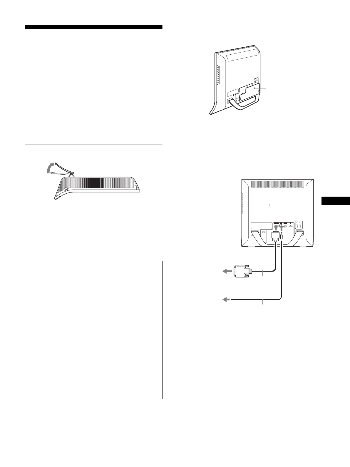
Setup 1:Open the stand
Remove the connector cover.
Push the hooks and draw the connector cover towards you.
connector cover
x Connecting a computer using the PC 1
connectors
If you intend to connect a computer equipped with a DVI
connector (digital RGB), follow the instructions below.
Using the supplied DVI-D video signal cable (digital
RGB) and the supplied audio cord, connect the
computer to the display’s PC 1 connectors.
Note
The stand is folded at the factory. Be sure not to place the display
vertically with the stand as it is. Otherwise, the display may topple over.
Setup 2:Connect the cables
• Turn off the display, computer, and other equipment
before connecting them.
• If you intend to connect:
– A computer equipped with an HD15 output connector
(analog RGB)
t See “Connecting a computer using the PC 2
connectors” on this page.
– Video equipment that has component video output
jacks
t See “Connecting video equipment using the
VIDEO 1 jacks” (page 10).
– Video equipment that has composite/S video output
jacks
t See “Connecting video equipment using the
VIDEO 2 jacks” (page 11).
–An antenna
t See “Connecting an antenna” (page 11).
Note
Do not touch the pins of the video signal cable connector as this might
bend the pins.
to the
audio input
for PC 1
to the computer’s DVI output
connector (digital RGB)
DVI-D video signal
to the audio output
of the computer
cable (digital RGB)
(supplied)
audio cord (supplied)
to the DVI-D
input
x Connecting a computer using the PC 2
connectors
If you intend to connect a computer equipped with an HD15
connector (analog RGB), follow the instructions below.
Using the supplied HD15-HD15 video signal cable
(analog RGB) and the supplied audio cord, connect the
computer to the display’s PC 2 connectors.
Connect the computer according to the following illustrations.
US
9
Page 10
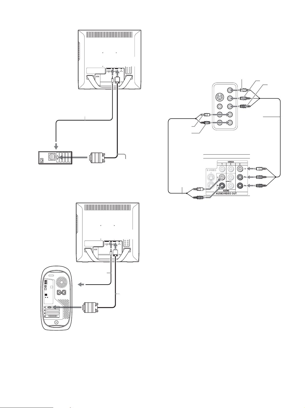
To connect to an IBM PC/AT or compatible computer
to the
audio input
for PC 2
to the HD15
input
x Connecting video equipment using the
VIDEO
If you intend to connect video equipment that has component
video output jacks, such as a DVD player, follow the instructions
below.
Using a video signal cable (not supplied) and an audio
cord (not supplied), connect the video equipment to the
display’s VIDEO 1 jacks.
1 jacks
audio cord (supplied)
IBM PC/AT
or compatible
computer
to the computer’s HD15
output connector (analog
RGB)
to the audio output
of the computer
To connect to a Macintosh computer
HD15-HD15 video
signal cable (analog
RGB) (supplied)
audio-L
(white)
audio-R
(red)
audio cord (not
supplied)
rear of the display
DVD player
Y
component
video cable
(not supplied)
P
B
P
R
to the
audio input
for PC 2
audio cord
(supplied)
to the audio output
of the computer
to the computer’s
output connector
Macintosh
When connecting a Macintosh computer, use an adapter (not supplied),
if necessary. Connect the adapter to the computer before connecting the
video signal cable.
to the HD15
input
HD15-HD15
video signal
cable (analog
RGB)
(supplied)
10
Page 11
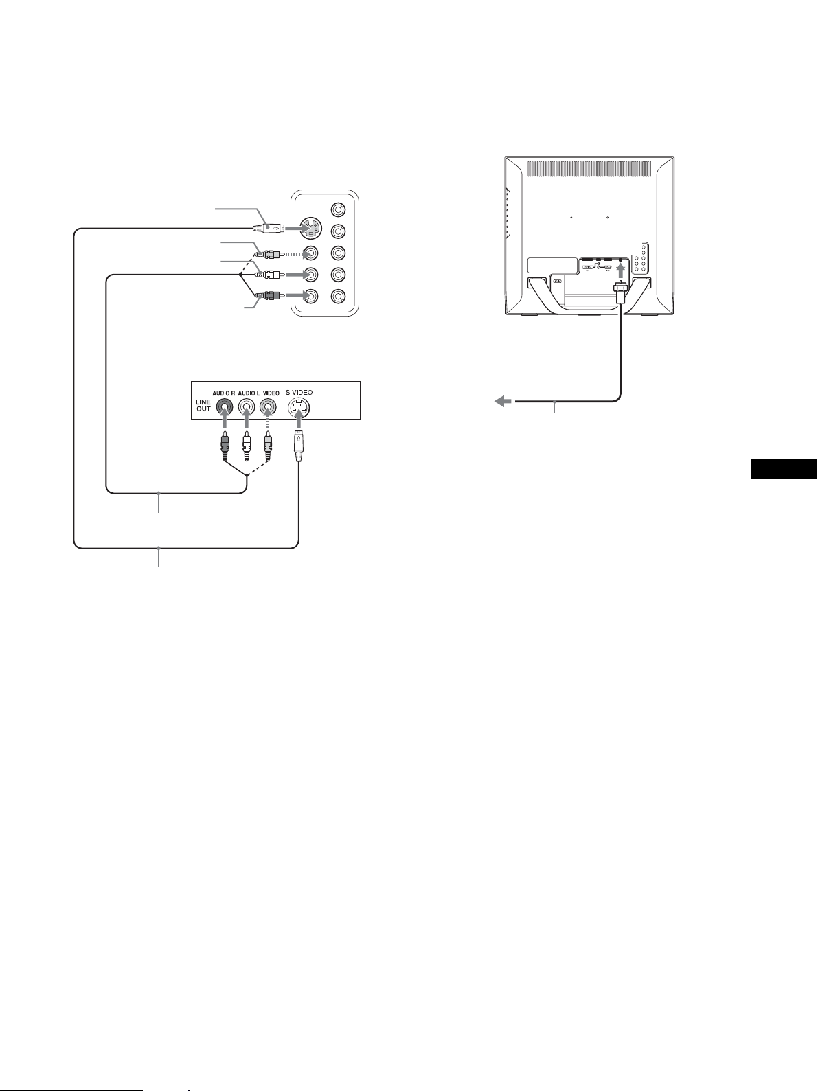
x Connecting video equipment using the
VIDEO
If you intend to connect video equipment that has composite/S
video output jacks, such as a VCR, follow the instructions below.
Using a video signal cable (not supplied) and an audio
cord (not supplied), connect the video equipment to the
display’s VIDEO 2 jacks.
2 jacks
rear of the display
S video
x Connecting an antenna
If you intend to connect an antenna to receive the TV signal,
follow the instructions below.
Using the 75-ohm coaxial cable (supplied), connect an
antenna to the display’s VHF/UHF jack.
video (yellow)
audio-L (white)
audio-R (red)
VCR
video and audio cable
(not supplied)
S video cable (not supplied)
Note
When you connect video equipment to both composite video
input and S video input jacks, the signal from the S video jack
is displayed.
to the VHF/UHF jack
to an antenna
75-ohm coaxial cable
(supplied)
US
Note
It is strongly recommended that you connect the antenna using a 75-ohm
coaxial cable to get optimum picture quality. A 300-ohm twin lead cable
can be easily affected by radio noise and the like, resulting in signal
deterioration. If you use a 300-ohm twin lead cable, keep it away as far as
possible from the display.
11
Page 12
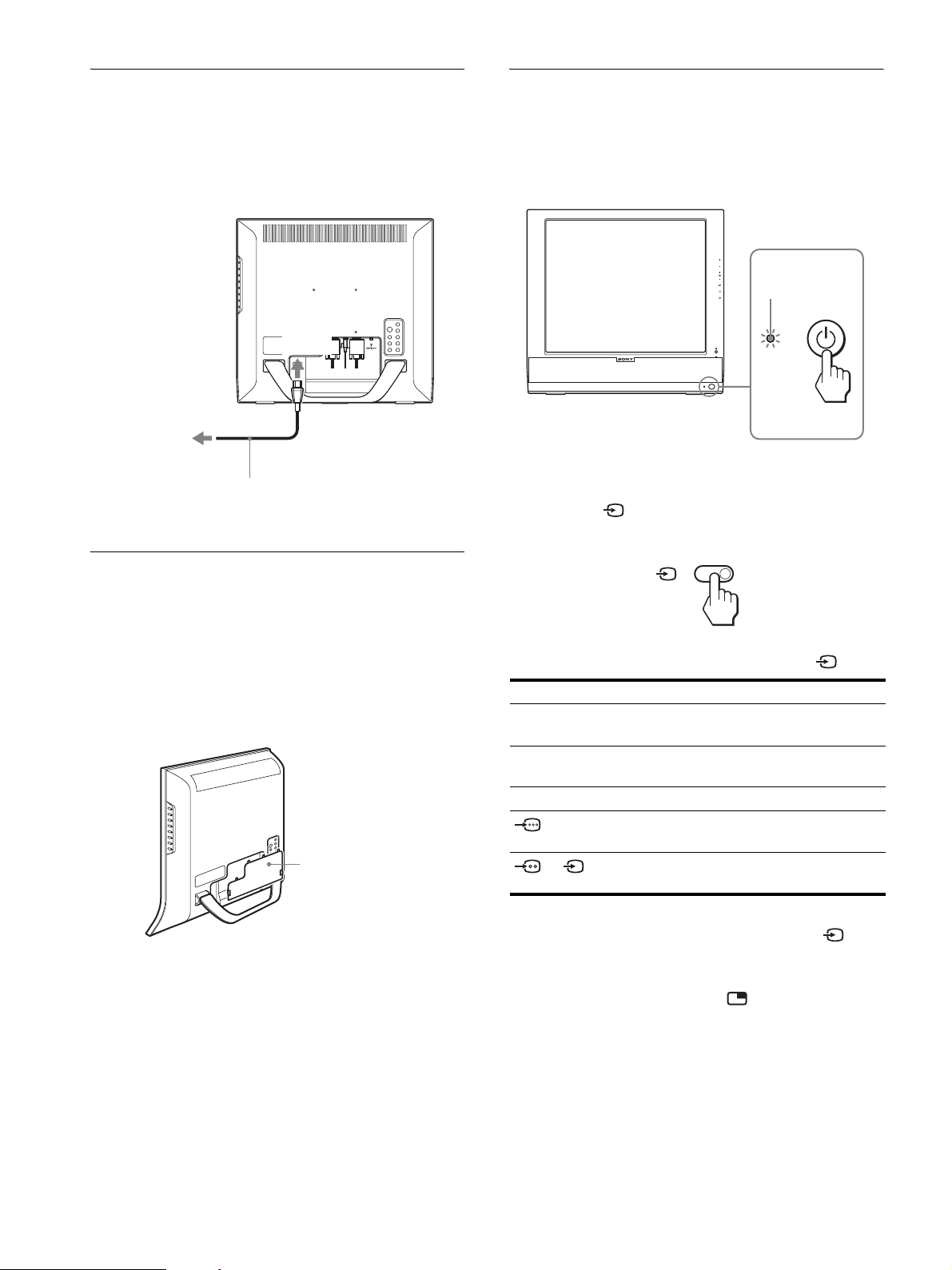
Setup 3:Connect the power cord
Setup 5:Turn on the display and
1 Connect the supplied power cord securely to the
display’s AC IN connector.
2 Connect the other end securely to a power outlet.
1
to
AC IN
2
to the power outlet
power cord (supplied)
Setup 4:Replace the connector
other equipment
1 Press the 1 (power) switch on the front of the
display.
The 1 (power) indicator lights up in green.
CH
lights in green
2 Turn on the computer or other video equipment.
3 Press the button to select the desired input
signal.
cover
While pressing the hooks, push the connector cover
onto the display until it clicks.
connector cover
The input signal will change each time you press the button.
On-screen message Input signal configuration
DVI-D: PC 1 DVI-D input connector (digital
RGB) for PC 1
HD15: PC 2 HD15 input connector
(analog RGB) for PC 2
TV channels TV
: VIDEO 1
Y/P
Component Video
B/PR
input jacks for VIDEO 1
or : VIDEO 2
Composite/S video input jacks
for VIDEO 2
Note
When using the PIP function, if you switch the input using the button
or input select buttons, the PIP function may be released. If it happens, the
input source that you have selected fills the entire screen. To use the PIP
function again, set the “PIP Setting” menu to “PIP On” using the menu
system or select “PIP On” by pressing the button (pages 15, 30).
Tips
• You can also select the inputs using the input select buttons on the
remote control.
• When you select the TV input, the number of the selected channel is
displayed in the upper right corner of the screen.
• When using the PIP function, use “Sub” in the “PIP” menu in the
“Option” menu to select the input source for sub picture (page 30). If
the TV input is selected for sub picture, you can change the channel
using the CH +/– buttons.
12
Page 13
If no picture appears on the screen
• Check that the power cord and the video signal cable are
properly connected.
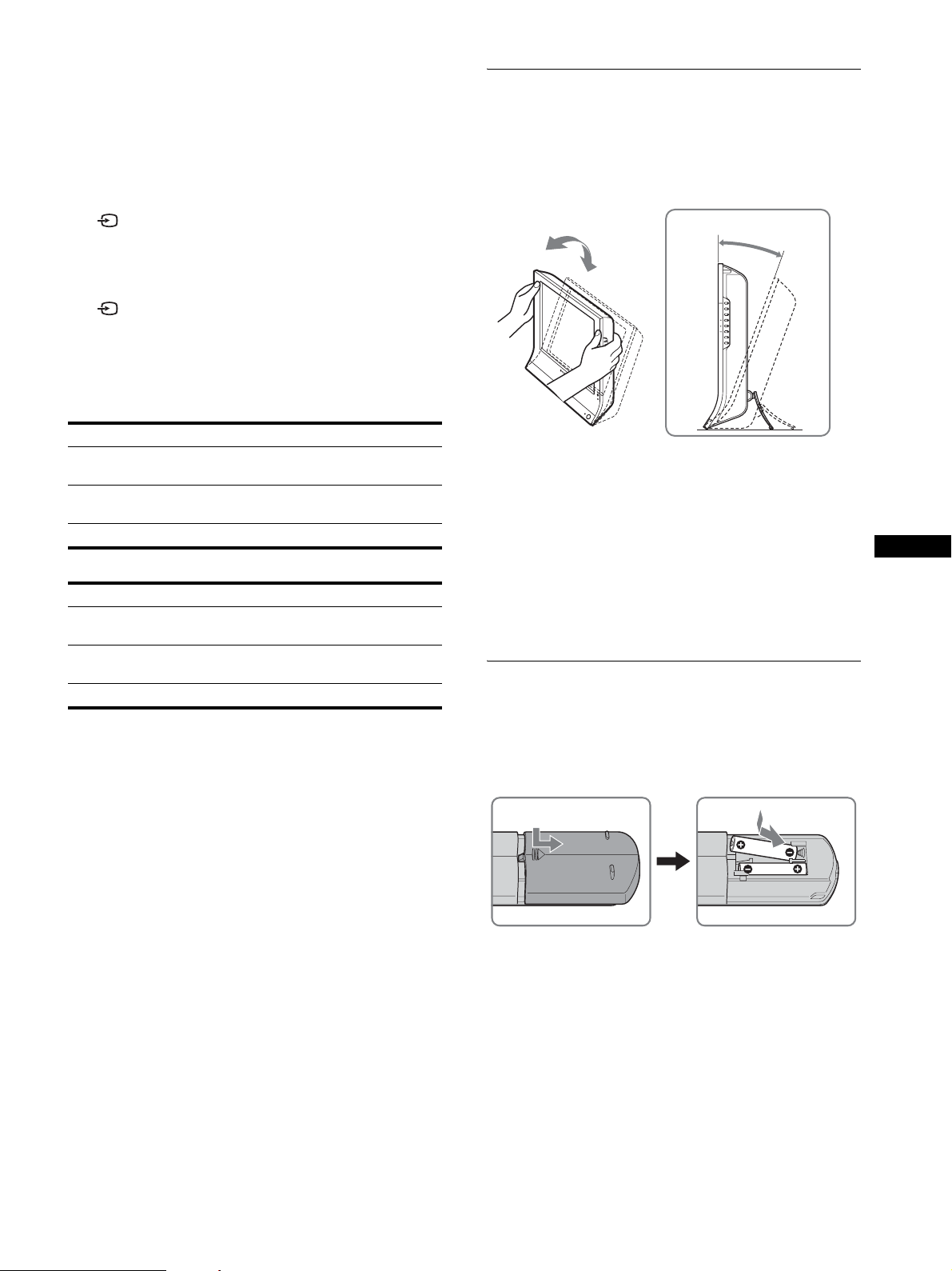
Setup 6:Adjust the tilt
This display can be adjusted within the angles shown below.
• If “No Input Signal” appears on the screen:
– The computer is in the power saving mode. Try pressing any
key on the keyboard or moving the mouse.
– Check that the input signal setting is correct by pressing the
button (page 12).
• If “Cable Disconnected” appears on the screen:
– Check that the video signal cable is properly connected.
– Check that the input signal setting is correct by pressing the
button (page 12).
• If “Out of Range” appears on the screen, reconnect the old
display. Then adjust the computer’s graphics board within the
following ranges.
MFM-HT75W
Analog RGB Digital RGB
Horizontal
frequency
Ver tic al
frequency
28–69 kHz 28–48 kHz
48–85 Hz 60 Hz
Resolution 1280 × 768 or less 1280 × 768 or less
MFM-HT95
Analog RGB Digital RGB
Horizontal
frequency
Ver tic al
frequency
28–86 kHz 28–64 kHz
48–85 Hz
1)
60 Hz
Resolution 1280 × 1024 or less 1280 × 1024 or less
1)
If the resolution is 1280 × 1024, the vertical frequency should be in the
range of 48–75 Hz.
For more information about on-screen messages, see “Trouble
symptoms and remedies” on page 38.
Grasp the sides of the LCD panel, then adjust the
screen angles.
approx.
20°
To use the display comfortably
Adjust the viewing angle of your display according to the height
of your desk and chair so that light is not reflected from the screen
to your eyes.
Notes
• When adjusting the screen tilt, proceed slowly and carefully, being sure
not to hit the display against the desk.
• When adjusting the screen tilt, make sure not to knock or drop the
display off the desk.
Setup 7:Insert batteries into the
remote control
Insert two size AAA batteries (supplied) by matching
the + and – marks on the batteries to the diagram inside
the remote control’s battery compartment.
US
No need for specific drivers
The display complies with the “DDC” Plug & Play standard and
automatically detects all the display’s information. No specific driver
needs to be installed on the computer.
The first time you turn on your computer after connecting the display, the
setup Wizard may appear on the screen. In this case, follow the on-screen
instructions. The Plug & Play display is automatically selected so that you
can use this display.
The vertical frequency is set to 60 Hz.
Since flickers are unobtrusive on the display, you can use it as it is. You
do not need to set the vertical frequency to any particular high value.
Notes
• Remove the batteries to avoid damage from possible battery leakage
whenever you anticipate that the remote control will not be used for an
extended period.
• Handle the remote control with care. Avoid dropping it, getting it wet,
or placing it in direct sunlight, near a heater or where the humidity is
high.
13
Page 14

Watching the TV
Setting the TV channels
To watch TV programs, you need to run “Auto Program” to set up
your channels.
Perform the following “Auto Program” procedure before you
watch TV programs for the first time.
For details on the use of the menu and buttons, see “Navigating
the menu” on page 15.
1 Press the MENU button.
Skipping unnecessary channels
You can skip unnecessary channels when selecting channels
using the CH +/– button.
1 Press the MENU button.
2 Press the M/m buttons to select (Channel) and
press the OK button.
The “Channel” menu appears on the screen.
3 Press the M/m buttons to select “Channel Skip/
Add” and press the OK button.
The “Channel Skip/Add” menu appears on the screen.
2 Press the M/m buttons to select (Channel) and
press the OK button.
The “Channel” menu appears on the screen.
3 Press the M/m buttons to select “Auto Program”
and press the OK button.
The “Auto Program” menu appears on the screen.
4 Press the M/m buttons to select “OK” and press the
OK button.
The display starts scanning and preparing channels
automatically.
Channel number and on-screen message appear.
5 Press the MENU button to exit the menu screen after
Auto Program is completed.
Changing the TV channel
Press the 0-9 buttons to input a channel number.
The channel changes after 3 seconds. Press the ENT (enter) button
to select immediately.
Use the CH +/– buttons to scan through the channels.
or
4 Press the M/m buttons to select the channel you
want to skip and press the OK button.
Tip
To scroll through the list, press and hold the M/m buttons.
5 Press the M/m buttons to select “Skip” and press
the OK button.
If you want to restore skipped channel, select “Add.”
6 Press the MENU button to exit the menu screen.
Choosing between cable and UHF/ VHF
To set the UHF/VHF channels, you need to set the “Cable” menu
to “Off” by following the instructions below.
1 Press the MENU button.
2 Press the M/m buttons to select (Channel) and
press the OK button.
The “Channel” menu appears on the screen.
3Press the M/m buttons to select “Cable” and press
the OK button.
The “Cable” menu appears on the screen.
4Press the M/ms buttons to select the desired mode
and press the OK button.
• On: The cable TV channels can be set.
• Off: The UHF/VHF channels can be set.
Tip
When you press and hold the CH + or – button, the channel number will
change rapidly.
14
Note
You cannot set and receive cable TV channels and UHF/VHF channels at
the same time.
Page 15

Using other features
You can also use the following TV features.
x Watching TV programs with closed captions
Set “Caption Vision” in the “Option” menu to “On.” For details,
see “Setting “Caption Vision” (for TV/VIDEO 1/VIDEO 2
only)” on page 32.
x Using the Parental Control feature
Select control options in the “Parent” menu. For details, see
“Parent menu” on page 25.
Customizing Your Display
Before making adjustments
Connect the display and equipment, then turn them on.
For the best results, wait for at least 30 minutes before making
adjustments.
You can make numerous adjustments to your display using the
on-screen menu.
Navigating the menu
Button operations (remote control)
Press To
MUTING Turn off the sound. Press it again or press VOL+
to restore sound (page 34).
DISPLAY Display the current channel number. Press it
again to turn the display off.
JUMP Jump back and forth between two channels. The
display alternates between the current channel
and the last channel.
SLEEP Turn off the display automatically after a
specified period of time (page 36).
Switch the Picture Mode (page 35).
Switch the “PIP” setting. Each time you press
this button, the setting changes as follows.
PIP On t PIP Off t PIP On...(page 30).
Switch the “Zoom” setting. Each time you press
this button, the setting changes as follows.
MFM-HT75W: Normal t Full t Wide Zoom
t Zoom t Normal...
MFM-HT95: Normal t Full t 16:9 t
Normal...
(page 22)
x When you use the buttons on the display
1 Display the main menu.
Press the MENU button to display the main menu on the
screen.
DVI-D: PC 1
1280 × 1024/60 Hz
OK
Set Exit
MENU
,
Picture
Mode: Movie
Backlight: 100
Contrast: 70
Brightness: 50
Color:
Hue:
Sharpness:
Color Temp.: 9300K
Gamma: Gamma4
Picture Mode Reset
NR:
Dynamic Picture:
Select
2 Select the menu.
Press the M/m buttons to display the desired menu. Press the
OK button to move to the first menu item.
,
US
Tip
The and buttons are also available on the display.
3 Select the item you want to adjust.
Press the M/m buttons to select the item you want to adjust,
then press the OK button.
,
If is one of the menu items.
When you select and press the OK button, the display returns to
the previous menu.
15
Page 16

4 Adjust the item.
Press the M/m buttons to make the adjustment, then press the
OK button.
When you press the OK button, the setting is stored, then the
display returns to the previous menu.
3 Select the item you want to adjust.
Press the M/m buttons to select the item you want to adjust,
then press the OK button.
,
5 Close the menu.
Press the MENU button once to return to normal viewing. If
no buttons are pressed, the menu closes automatically after
about 45 seconds.
x When you use the buttons on the remote
control
1 Display the main menu.
Press the MENU button to display the main menu on the
screen.
DVI-D: PC 1
1280 × 1024/60 Hz
OK
Set Exit
MENU
MENU
,
Picture
Mode: Movie
Backlight: 100
Contrast: 70
Brightness: 50
Color:
Hue:
Sharpness:
Color Temp.: 9300K
Gamma: Gamma4
Picture Mode Reset
NR:
Dynamic Picture:
Select
OK
If is one of the menu items.
When you select and press the OK button, the display returns to
the previous menu.
,
OK
4 Adjust the item.
Press the M/m buttons to make the adjustment, then press the
OK button.
When you press the OK button, the setting is stored, then the
display returns to the previous menu.
OK
,
OK
5 Close the menu.
Press the MENU button once to return to normal viewing. If
no buttons are pressed, the menu closes automatically after
about 45 seconds.
MENU
2 Select the menu.
Press the M/m buttons to display the desired menu. Press the
OK button to move to the first menu item.
OK
,
OK
16
x Resetting the adjustments to the default
settings
You can reset the adjustments using the “All Reset” menu. For
more information about resetting the adjustments, see “Resetting
to the default setting” on page 33.
Page 17

Picture menu
You can adjust the following items using the “Picture” menu.
• Mode
Backlight
Contrast (Picture)
Brightness
Color
Hue
Sharpness
Color Temp.
Gamma
Picture
Mode: Movie
Backlight: 100
Contrast: 70
Brightness: 50
Color:
Hue:
Sharpness:
Color Temp.: 9300K
Gamma: Gamma4
Picture Mode Reset
NR:
Dynamic Picture:
Select
Picture Mode Reset
•NR
• Dynamic Picture
Tip
The “Backlight,” “Contrast,” “Brightness,” “Color,” “Hue,” “Sharpness,”
“Color Temp.,” and “Gamma” menus can be set for each Picture mode.
Also, Picture Mode can be set for each available input.
x Selecting the Picture Mode for PC 1/PC 2
You can select the appropriate screen brightness for your purpose.
1 Press the MENU button.
The main menu appears on the screen.
2 Press the M/m buttons to select (Picture) and
press the OK button.
The “Picture” menu appears on the screen.
3 Press the M/m buttons to select “Mode” and press
the OK button.
The “Mode” menu appears on the screen.
Picture
Mode: Game
Backlight: Movie
Contrast: PC
Brightness: Auto
Color:
Hue:
Sharpness:
Color Temp.: 9300K
Gamma: Gamma4
Picture Mode Reset
NR:
Dynamic Picture:
Select
DVI-D: PC 1
1280 × 1024/60 Hz
OK
Set
MENU
Exit
DVI-D: PC 1
1280 × 1024/60 Hz
OK
Set Exit
MENU
x Selecting the Picture Mode for TV/VIDEO 1/
VIDEO 2
You can select the appropriate screen brightness for your purpose.
1 Press the MENU button.
The main menu appears on the screen.
2 Press the M/m buttons to select (Picture) and
press the OK button.
The “Picture” menu appears on the screen.
3 Press the M/m buttons to select “Mode” and press
the OK button.
The “Mode” menu appears on the screen.
OK
Set Exit
: TV
MENU
Picture
Mode: Vivid
Backlight: Standard
Picture: ECO
Brightness: Auto
Color: 50
Hue: 0
Sharpness: 7
Color Temp.:
Gamma:
Picture Mode Reset
NR: Off
Dynamic Picture: Off
Select
4 Press the M/m buttons to select the desired mode
and press the OK button.
The default setting is “Vivid.”
• Vivid: Picture with enhanced contrast and sharpness.
• Standard:Picture with contrast that suits the room light.
• ECO: Picture with low brightness.
• Auto: Automatically adjusts the screen brightness
according to the brightness of the surroundings
(automatic brightness adjustment function). For
more information, see “Automatic brightness
adjustment function (light sensor)” on page 35.
Note
When the Picture Mode is set to “Auto,” you cannot adjust the backlight.
US
4 Press the M/m buttons to select the desired mode
and press the OK button.
The default setting is “Movie.”
• Game: Bright picture.
• Movie: Clear picture with strong contrast.
• PC: Soft tone picture.
• Auto: Automatically adjusts the screen brightness
according to the brightness of the surroundings
(automatic brightness adjustment function). For
more information, see “Automatic brightness
adjustment function (light sensor)” on page 35.
Note
When the Picture Mode is set to “Auto,” you cannot adjust the backlight.
17
Page 18

x Adjusting “Backlight”
If the screen is too bright, adjust the backlight to make the screen
easier to see.
x Adjusting “Color” (for TV/VIDEO 1/VIDEO 2
only)
You can change the color intensity of the picture displayed.
1 Press the MENU button.
The main menu appears on the screen.
2 Press the M/m buttons to select (Picture) and
press the OK button.
The “Picture” menu appears on the screen.
3 Press the M/m buttons to select “Backlight” and
press the OK button.
The “Backlight” menu appears on the screen.
4 Press the M/m buttons to adjust the light level and
press the OK button.
x Adjusting “Contrast” (“Picture”)
You can adjust the picture contrast. The “Contrast” menu is
available only for the PC 1 or PC 2 input. When you select the
VIDEO 1, VIDEO 2, or TV input, the “Picture” menu is available
instead.
1 Press the MENU button.
The main menu appears on the screen.
2 Press the M/m buttons to select (Picture) and
press the OK button.
The “Picture” menu appears on the screen.
3 Press the M/m buttons to select “Contrast”
(“Picture”) and press the OK button.
The “Contrast” (“Picture”) menu appears on the screen.
1 Press the MENU button.
The main menu appears on the screen.
2 Press the M/m buttons to select (Picture) and
press the OK button.
The “Picture” menu appears on the screen.
3 Press the M/m buttons to select “Color” and press
the OK button.
The “Color” menu appears on the screen.
4Press the M/m buttons to adjust the color intensity
and press the OK button.
x Adjusting “Hue” (for TV/VIDEO 2 only)
You can change the color tones of the picture displayed.
1 Press the MENU button.
The main menu appears on the screen.
2 Press the M/m buttons to select (Picture) and
press the OK button.
The “Picture” menu appears on the screen.
3 Press the M/m buttons to select “Hue” and press
the OK button.
The “Hue” menu appears on the screen.
4 Press the M/m buttons to adjust the hue and press
the OK button.
4 Press the M/m buttons to adjust the contrast and
press the OK button.
x Adjusting “Brightness”
You can adjust the picture brightness (black level).
1 Press the MENU button.
The main menu appears on the screen.
2 Press the M/m buttons to select (Picture) and
press the OK button.
The “Picture” menu appears on the screen.
3 Press the M/m buttons to select “Brightness” and
press the OK button.
The “Brightness” menu appears on the screen.
4 Press the M/m buttons to adjust the brightness and
press the OK button.
x Adjusting “Sharpness” (for TV/VIDEO 1/
VIDEO 2 only)
You can adjust the sharpness of the edges of images, etc.
1 Press the MENU button.
The main menu appears on the screen.
2 Press the M/m buttons to select (Picture) and
press the OK button.
The “Picture” menu appears on the screen.
3 Press the M/m buttons to select “Sharpness” and
press the OK button.
The “Sharpness” menu appears on the screen.
4Press the M/m buttons to adjust the sharpness and
press the OK button.
Note
If the input from VIDEO 1 is selected and the video signal being input is
1080i format, “Sharpness” is unavailable.
18
Page 19

x Adjusting “Color Temp.” (for PC 1/PC 2
only)
You can select the picture’s color level for the white color field
from the default color temperature settings.
Also, if necessary, you can fine tune the color temperature.
1 Press the MENU button.
The main menu appears on the screen.
2 Press the M/m buttons to select (Picture) and
press the OK button.
The “Picture” menu appears on the screen.
3 Press the M/m buttons to select “Color Temp.” and
press the OK button.
The “Color Temp.” menu appears on the screen.
Picture
Mode: Movie
Backlight: 100
Contrast: 70
Brightness: 50
Color:
Hue:
Sharpness:
Color Temp.: 9300K
Gamma: 6500K
Picture Mode Reset sRGB
NR: User
Dynamic Picture: Adjust
Select
DVI-D: PC 1
1280 × 1024/60 Hz
OK
Set Exit
MENU
4 Press the M/m buttons to select the desired color
temperature and press the OK button.
White balance changes from bluish to reddish as the color
temperature is adjusted from 9300K to 6500K.
When you select “sRGB,” the colors adjust to the sRGB
profile. (The sRGB color setting is an industry-standard color
space protocol designed for computer products.) If you select
“sRGB,” the color settings of your computer must be set to the
sRGB profile.
Notes
• If a connected computer or other equipment is not sRGB-compliant,
color cannot be adjusted to the sRGB profile.
• You cannot select “sRGB” when the Picture Mode is set to “Auto.”
• If you select “sRGB,” you cannot adjust “Contrast” and “Brightness”
in the “Picture” menu. Also, you cannot adjust “Gamma.”
Fine tuning the color temperature
1 Press the MENU button.
The main menu appears on the screen.
2 Press the M/m buttons to select (Picture) and
press the OK button.
The “Picture” menu appears on the screen.
The fine tuning menu for color temperature appears on the
screen.
R 160
G 127
B 75
5 Press the M/m buttons to select R (Red) or B (Blue)
and press the OK button. Then press the M/m
buttons to adjust the color temperature and press
the OK button.
Since this adjustment changes the color temperature by
increasing or decreasing the R and B components with respect
to G (green), the G component is fixed.
6 Press the M/m buttons to select , then press the
OK button.
The new color setting is stored in memory and automatically
recalled whenever “User” is selected.
The “Color Temp.” menu appears on the screen.
x Adjusting “Gamma” (for PC 1/PC 2 only)
You can associate the picture’s color shade on the screen with the
picture’s original color shade.
1 Press the MENU button.
The main menu appears on the screen.
2 Press the M/m buttons to select (Picture) and
press the OK button.
The “Picture” menu appears on the screen.
3 Press the M/m buttons to select “Gamma” and
press the OK button.
The “Gamma” menu appears on the screen.
Picture
Mode: Movie
Backlight: 100
Contrast: 70
Brightness: 50
Color:
Hue:
Sharpness:
Color Temp.: 9300K
Gamma: Gamma1
Picture Mode Reset Gamma2
NR: Gamma3
Dynamic Picture: Gamma4
Select
4 Press the M/m buttons to select the desired mode
and press the OK button.
DVI-D: PC 1
1280 × 1024/60 Hz
OK
Set Exit
MENU
US
3 Press the M/m buttons to select “Color Temp.” and
press the OK button.
The “Color Temp.” menu appears on the screen.
4 Press the M/m buttons to select “Adjust” and press
the OK button.
19
Page 20

x Resetting Picture Mode to the default
You can reset the adjustments to the default settings.
1 Press the MENU button.
The main menu appears on the screen.
2 Press the M/m buttons to select (Picture) and
press the OK button.
The “Picture” menu appears on the screen.
3 Press the M/m buttons to select “Picture Mode
Reset” and press the OK button.
The “Picture Mode Reset” menu appears on the screen.
Picture
Mode: Movie
Backlight: 100
Contrast: 70
Brightness: 50
Color:
Hue:
Sharpness:
Color Temp.: 9300K
Gamma: Gamma4
Picture Mode Reset OK
NR: Cancel
Dynamic Picture:
Select
4 Press the M/m buttons to select the desired mode
and press the OK button.
• OK: To reset the all items in the current Picture
Mode to the default.
• Cancel: To cancel resetting and return to the “Picture”
menu.
DVI-D: PC 1
1280 × 1024/60 Hz
OK
Set Exit
MENU
x Setting “Dynamic Picture” (for TV/VIDEO 1/
VIDEO 2 only)
You can set the “Dynamic Picture” function to on or off.
This feature can be set for each available input.
1 Press the MENU button.
The main menu appears on the screen.
2 Press the M/m buttons to select (Picture) and
press the OK button.
The “Picture” menu appears on the screen.
3Press the M/m buttons to select “Dynamic Picture”
and press the OK button.
The “Dynamic Picture” menu appears on the screen.
OK
Set Exit
: TV
MENU
Picture
Mode: Vivid
Backlight: 100
Picture: 70
Brightness: 50
Color: 50
Hue: 0
Sharpness: 7
Color Temp.:
Gamma:
Picture Mode Reset
NR: Off
Dynamic Picture: On
Off
Select
4 Press the M/m buttons to select the desired mode
and press the OK button.
• On: The picture contrast is enhanced.
• Off: The “Dynamic Picture” function is turned off.
x Setting “NR” (for TV/VIDEO 1/VIDEO 2 only)
You can set the noise reduction function to on or off.
This feature can be set for each available input.
1 Press the MENU button.
The main menu appears on the screen.
2 Press the M/m buttons to select (Picture) and
press the OK button.
The “Picture” menu appears on the screen.
3 Press the M/m buttons to select “NR” and press the
OK button.
The “NR” menu appears on the screen.
OK
Set Exit
: TV
MENU
Picture
Mode: Vivid
Backlight: 100
Picture: 70
Brightness: 50
Color: 50
Hue: 0
Sharpness: 7
Color Temp.:
Gamma:
Picture Mode Reset
NR: On
Dynamic Picture: Off
Select
4 Press the M/m buttons to select the desired mode
and press the OK button.
• On: The noise level is reduced.
• Off: The noise reduction function is turned off.
20
Page 21

Audio menu
You can adjust the following items using the “Audio” menu.
The items in the “Audio” menu can be set for each available input.
• Surround
•Treble
•Bass
• Balance
•Auto Volume
Audio
Surround: SRS WOW
Tre bl e : 0
Bass: 0
Balance: 0
Auto Volume: On
MTS: Stereo
Audio Reset
•MTS
•Audio Reset
Select
x Setting “Surround”
1 Press the MENU button.
The main menu appears on the screen.
2 Press the M/m buttons to select (Audio) and
press the OK button.
The “Audio” menu appears on the screen.
3 Press the M/m buttons to select “Surround” and
press the OK button.
The “Surround” menu appears on the screen.
OK
Set Exit
: TV
MENU
Audio
Surround: SRS WOW
Treble: Off
Bass: 0
Balance: 0
Auto Volume: On
MTS: Stereo
Audio Reset
Select
4 Press the M/m buttons to select the desired mode
and press the OK button.
• SRS WOW: Deep rich bass tone and clear high tone
creates a rich surround sound experience,
and movies and games, especially, can be
enjoyed with powerful sound.
• Off: Turns off the SRS WOW effect.
Adopting the latest technology developed by SRS Labs, Inc., SRS
WOW significantly improves the sound quality of various audio
sources.
OK
Set Exit
: TV
MENU
x Adjusting “Treble,” “Bass,” and “Balance”
1 Press the MENU button.
The main menu appears on the screen.
2 Press the M/m buttons to select (Audio) and
press the OK button.
The “Audio” menu appears on the screen.
3 Press the M/m buttons to select “Treble,” “Bass,” or
“Balance” and press the OK button.
4 Press the M/m buttons to adjust the level and press
the OK button.
x Setting “Auto Volume” (for TV/VIDEO 1/
VIDEO 2 only)
You can set the loudness of the sound to keep it at a specified
level.
1 Press the MENU button.
The main menu appears on the screen.
2 Press the M/m buttons to select (Audio) and
press the OK button.
The “Audio” menu appears on the screen.
3 Press the M/m buttons to select “Auto Volume” and
press the OK button.
The “Auto Volume” menu appears on the screen.
OK
Set Exit
: TV
MENU
Audio
Surround: SRS WOW
Treble: 0
Bass: 0
Balance: 0
Auto Volume: On
MTS: Off
Audio Reset
Select
4 Press the M/m buttons to select the desired mode
and press the OK button.
• On: Loudness of the sound stays at the specified level,
independent of the broadcast signal (e.g. in the case
of advertisements).
• Off: Loudness of the sound changes automatically
according to the broadcast signal.
US
21
Page 22

x Setting “MTS” (for TV only)
You can enjoy stereo, bilingual, and monaural programs.
Screen menu
1 Press the MENU button.
The main menu appears on the screen.
2 Press the M/m buttons to select (Audio) and
press the OK button.
The “Audio” menu appears on the screen.
3 Press the M/m buttons to select “MTS” and press
the OK button.
The “MTS” menu appears on the screen.
OK
Set Exit
: TV
MENU
Audio
Surround: SRS WOW
Tre bl e : 0
Bass: 0
Balance: 0
Auto Volume: On
MTS: Stereo
Audio Reset Auto SAP
Mono
Select
4 Press the M/m buttons to select the desired mode
and press the OK button.
• Stereo: Stereo sound is output when viewing a
program broadcast in stereo.
• Auto SAP: A second audio program channel is output
automatically when a signal received. (If no
SAP signal is present, the display remains in
stereo mode.)
• Mono: Monaural sound is output. (Use to reduce
noise during weak stereo broadcasts.)
x Resetting all audio settings to the default
You can reset the adjustments to the default settings.
1 Press the MENU button.
The main menu appears on the screen.
2 Press the M/m buttons to select (Audio) and
press the OK button.
The “Audio” menu appears on the screen.
You can adjust the following items using the “Screen” menu.
•Zoom
•Auto Adjust
•Phase
•Pitch
•H Center
Screen
Zoom :
Auto Adjust
Phase : 30
Pitch : 0
H Center : 50
V Center : 50
HD15: PC 2
•V Center
Select
1280 × 1024/60 Hz
Set Exit
MENU
OK
x Setting “Zoom”
This feature lets you watch 4:3 normal broadcasts or other picture
sizes such as Letter box movies in several “Zoom” modes.
A “Zoom” value is set for each available input.
Tip
You can also switch the “Zoom” setting by pressing the button on the
remote control repeatedly.
1 Press the MENU button.
The main menu appears on the screen.
2 Press the M/m buttons to select (Screen) and
press the OK button.
The “Screen” menu appears on the screen.
3Press the M/m buttons to select “Zoom” and press
the OK button.
The “Zoom” menu appears on the screen.
MFM-HT75W
Screen
Zoom :
Normal
Auto Adjust
Full
Phase :
Wide Zoom
Pitch :
Zoom
H Center :
V Center :
: TV
3 Press the M/m buttons to select “Audio Reset” and
press the OK button.
The “Audio Reset” menu appears on the screen.
OK
Set Exit
: TV
MENU
Audio
Surround: SRS WOW
Tre bl e : 0
Bass: 0
Balance: 0
Auto Volume: On
MTS: Stereo
Audio Reset OK
Cancel
Select
4 Press the M/m buttons to select the desired mode
and press the OK button.
• OK: To reset the all items in the “Audio” menu to the
default.
• Cancel: To cancel resetting and return to the “Audio”
menu.
22
MFM-HT95
Select
Screen
Zoom :
Normal
Auto Adjust
Full
Phase :
16 : 9
Pitch :
H Center :
V Center :
Select
OK
Set Exit
OK
Set Exit
MENU
: TV
MENU
Page 23

4 Press the M/m buttons to select the desired mode
and press the OK button.
x Automatic picture quality adjustment
function (for PC 2 only)
For the MFM-HT75W
• Normal: Original size.
• Full: A picture is enlarged horizontally (linear) to
fill the 15:9 screen. Useful for viewing
Squeeze signal.
• Wide Zoom: A picture is enlarged horizontally (non-
linear) to fill the 15:9 screen, keeping the
original image as much as possible.
• Zoom: A picture is enlarged horizontally and
vertically to an equal aspect ratio that fills a
15:9 screen. Useful for viewing Letter Box
signal.
Notes
• If the input from either PC 1 or PC 2 is selected, “Zoom” and
“Wide Zoom” are unavailable.
• If the input from VIDEO 1 is selected and the video signal being
input is 1080i format, “Wide Zoom” is unavailable.
For the MFM-HT95
• Normal: Original size.
• Full: A picture is enlarged horizontally (linear) to fill
the 5:4 screen. Useful for viewing 4:3 signal or
Letter Box signal.
• 16:9: A picture is squeezed horizontally to an equal
aspect ratio that fills the 5:4 screen. Useful for
viewing Squeeze signal.
Notes
• If the input from either PC 1 or PC 2 is selected, all three options
are unavailable.
• If the input from VIDEO 1 is selected and the video signal being
input is either 1080i, 1035i, or 720p format, “16:9” and “Full” are
unavailable.
Tip
When the picture that looks like as illustrated below is displayed,
even if the input from VIDEO 1 selected and the video signal being
input is either 1080i or 720p format, “Full” is available.
When the display receives an input signal, it automatically
adjusts the picture’s position and sharpness (phase/pitch), and
ensures that a clear picture appears on the screen (page 35).
Note
While the automatic picture quality adjustment function is activated, only
the 1 (power) switch will operate.
If the automatic picture quality adjustment function of this
display seems to not completely adjust the picture
You can make further automatic adjustment of the picture quality for the
current input signal (See “Auto Adjust” below).
If you still need to make further adjustments to the picture
quality
You can manually adjust the picture’s sharpness (phase/pitch) and
position (horizontal/vertical position).
These adjustments are stored in memory and automatically
recalled when the display receives a previously input and
registered input signal.
x Making further automatic adjustments to
the picture quality for the current input
signal (Auto Adjust) (for PC 2 only)
1 Press the MENU button.
The main menu appears on the screen.
2 Press the M/m buttons to select (Screen) and
press the OK button.
The “Screen” menu appears on the screen.
3 Press the M/m buttons to select “Auto Adjust” and
press the OK button.
Make the appropriate adjustments of the screen’s phase, pitch
and horizontal/vertical position for the current input signal
and store them.
US
23
Page 24

x Adjusting the picture’s sharpness manually
(Phase/Pitch) (for PC 2 only)
You can adjust the picture’s sharpness as follows.
1 Set the resolution to 1280 × 768 (MFM-HT75W), or
1280 × 1024 (MFM-HT95) on the computer.
2 Load the CD-ROM.
3 Start the CD-ROM, select the area and model, and
display the test pattern.
For Windows
Click [Utility] t [Windows]/[Win Utility.exe].
For Macintosh
Click [Utility] t [Mac]/[Mac Utility].
4 Press the MENU button.
The main menu appears on the screen.
5 Press the M/m buttons to select (Screen) and
press the OK button.
The “Screen” menu appears on the screen.
6 Press the M/m buttons to select “Phase” and press
the OK button.
The “Phase” adjustment menu appears on the screen.
7 Press the M/m buttons until the horizontal stripes
are at a minimum.
Adjust so that the horizontal stripes are at a minimum.
x Adjusting the picture’s position manually
(H Center /V Center) (for PC 2 only)
If the picture is not in the center of the screen, adjust the picture’s
centering as follows.
1 Set the resolution to 1280 × 768 (MFM-HT75W), or
1280 × 1024 (MFM-HT95) on the computer.
2 Load the CD-ROM.
3 Start the CD-ROM, select the area and model, and
display the test pattern.
For Windows
Click [Utility] t [Windows]/[Win Utility.exe].
For Macintosh
Click [Utility] t [Mac]/[Mac Utility].
4 Press the MENU button.
The main menu appears on the screen.
5 Press the M/m buttons to select (Screen) and
press the OK button.
The “Screen” menu appears on the screen.
6 Press the M/m buttons to select “H Center” or “V
Center” and press the OK button.
The “H Center” adjustment menu or “V Center” adjustment
menu appears on the screen.
7 Press the M/m buttons to center the test pattern on
the screen.
8 Press the OK button.
The main menu appears on the screen.
If vertical stripes are observed over the entire screen, adjust
the pitch using the following procedures.
9 Press the M/m buttons to select “Pitch” and press
the OK button.
The “Pitch” adjustment menu appears on the screen.
10 Press the M/m buttons until the vertical stripes
disappear.
Adjust so that the vertical stripes disappear.
11 Click [END] on the screen to turn off the test pattern.
8Click [END] on the screen to turn off the test pattern.
24
Page 25

Parent menu
TV programs and movies shown on TV are given a rating signal
based on the following rating systems.
In the U.S.A.: U.S. Television Parental Guidelines to rate
television programs (U.S. TV ratings), and Motion Picture
Association of America (MPAA) Guidelines to rate movies
including those shown on TV (movie ratings).
In Canada: Canadian English Language ratings to rate television
programs in English, and Canadian French Language ratings to
rate those in French.
4 Press the M/m buttons to select “Select Country”
and press the OK button.
OK
Set Exit
: TV
MENU
Parent
Lock: Off
Select Country: U.S.A.
Change Password Canada
Select
5 Press the M/m buttons to select your country/
region (U.S.A. or Canada) and press the OK button.
To block programs you feel unsuitable for your children, you need
to set the display for the desired rating systems. Sony’s
predetermined ratings are also available. See page 28 for a
description of the ratings.
The TV’s Parental Control feature functions by receiving the
rating signal from your local broadcasting station or cable service
provider.
x Activating the Parental Control feature
1 Press the MENU button.
2 Press the M/m buttons to select (Parent) and
press the OK button.
OK
Set Exit
: TV
MENU
: TV
Parent
Enter password
using 0 - 9 buttons
----
Select
3 Enter a four-digit password using the 0-9 buttons.
The “Parent” menu appears on the screen.
Parent
Lock: Off
Select Country: U.S.A.
Change Password
6 Press the M/m buttons to select “Lock” and press
the OK button.
OK
Set Exit
: TV
MENU
Parent
Lock: Off
Select Country: Child
Change Password Youth
Y.Adult
Custom
Select
7 Press the M/m buttons to select a desired rating and
press the OK button.
If you select “Child,” “Youth,” or “Y.Adult” (Young Adult),
the level of Parental Control is activated automatically.
Tip
If you are not familiar with the Parental Guideline rating system, you
should select “Child,” “Youth,” or “Y.Adult” to help simplify the
rating selection. To set more restrictive ratings, select “Custom” (see
“Selecting a Custom Rating” on page 26).
8 Press the MENU button to exit the menu screen.
To deactivate the Parental Control feature
Set “Lock” to “Off” in the “Parent” menu.
To change the password
1 Press the MENU button.
US
MENU
OK
Set Exit
Select
If you access the “Parent” menu for the first time, you are
requested to enter the password again for confirmation.
Note
Do not enter “4357” corresponding to “HELP” on a phone number
pad (see page 26).
Tips
• You need to enter the password here for any further access to the
“Parent” menu. If you lose your password, see “Tip” on page 26.
• If you want to change the password, see page 25.
2 Press the M/m buttons to select (Parent) and
press the OK button.
3 Enter your four-digit password using the 0-9
buttons.
The “Parent” menu appears on the screen.
4 Press the M/m buttons to select “Change
Password” then press the OK button.
5 Enter a new four-digit password using the 0-9
buttons.
6 Enter the password set in step 5 again to confirm.
7 Press the MENU button to exit the menu screen.
25
Page 26

Tip
If you have forgotten your password, enter the master password “4357”
(corresponding to “HELP” on a phone number pad) in step 3. You can
then store a new password.
Notes
• If you entered “4357” as your password for the first time, you cannot
store a new password (see step 3 of “Activating the Parental Control
feature” on page 25).
• When you select a Parental Control program and the indicator is
displayed on the screen, you cannot view that program even if you enter
“4357”.
x Selecting a Custom Rating
If you want to select the ratings to be blocked from “Custom”
once you have activated the Parental Control feature (page 25),
follow the procedure below.
For a detailed description of each rating, see “What the Ratings
Mean” on page 28.
1 Perform steps 1 to 6 in “Activating the Parental
Control feature” on page 25 to display the “Lock”
menu.
2 Press the M/m buttons to select “Custom” and
press the OK button.
In the U.S.A.
OK
Set Exit
: TV
MENU
: TV
In Canada
Parent
Custom
Movie Rating
TV Rating
Unrated : Allow
Select
Parent
Custom
English Rating
French Rating
U.S.A Rating
MENU
OK
Set Exit
Select
To select a rating in Canada, go to step 6.
3 Press the M/m buttons to select “Movie Rating” and
press the OK button.
OK
Set Exit
: TV
MENU
Parent
Movie Rating
G: –
PG: –
PG-13: –
R: –
NC-17: –
X: –
Select
4 Press the M/m buttons to select the rating to be
blocked and press the OK button.
The indicator automatically appears beside the selected
rating and all ratings below it, indicating that the programs
that match the ratings will be blocked.
To unlock a rating, select and press the OK button.
The indicator changes to “–” and all ratings above it are
unlocked.
5 Press the M/m buttons to select and press the OK
button.
26
6 To select a TV rating in the U.S.A.:
Page 27

Press the M/m buttons to select “TV Rating” and press the
OK button.
OK
Set Exit
: TV
MENU
Parent
TV Rating
Rating Content
TV-Y: –
TV-Y7: – FV: –
TV-G: –
TV-PG: – D:– L: – S: – V: –
TV-14: – D:– L: – S: – V: –
TV-MA: – L: – S: – V: –
Select
To select a TV rating in Canada:
Press the M/m buttons to select “English Rating,” “French
Rating,” or “U.S.A. Rating” and press the OK button.
English Rating
OK
Set Exit
OK
Set Exit
: TV
: TV
MENU
: TV
MENU
French Rating
U.S.A. Rating
Parent
English Rating
C: –
C8+: –
G: –
PG: –
14+: –
18+: –
Select
Parent
French Rating
G: –
8ans+: –
13ans+: –
16ans+: –
18ans+: –
Select
Parent
U.S.A. Rating
Rating Content
TV-Y: –
TV-Y7: – FV: –
TV-G: –
TV-PG: – D:– L: – S: – V: –
TV-14: – D:– L: – S: – V: –
TV-MA: – L: – S: – V: –
To unlock a rating, select and press the OK button.
The indicator changes to “–” and all ratings above it are
unlocked.
Some U.S. TV ratings have additional content ratings called
“extenders.”
The extenders are defined as follows:
D (sexually suggestive Dialogue), FV (Fantasy Violence), L
(coarse Language), S (Sexual situations) and V (Violence).
By setting the extenders, you can define additional viewing
limits.
For more details of extenders, see page 28.
All of the extenders included in the selected ratings will be
blocked. If you want to allow any of them to be viewed, go to
step 8. Otherwise, go to step 10.
8 Press the M/m buttons to select the extender to be
viewed and press the OK button.
“–” appears beside the selected extender, indicating that the
programs that match the extender can be viewed.
To relock the canceled extender, select .
The indicator appears to show that the programs that match
the extender will be blocked again.
9 Repeat step 8 for other extenders.
All programs that match the ratings you select and higher,
except for the extenders that were canceled, will be blocked.
10 Press the MENU button to exit the menu screen.
To block programs or movies broadcast without a
rating
The unrated option allows you to block programs or movies that
are broadcast without a rating.
The unrated option is available only when you have selected
“U.S.A.” as your country/region.
1 Perform steps 1 and 2 of “Selecting a Custom
Rating” on page 26.
2 Press the M/m buttons to select “Unrated” and
press the OK button.
US
MENU
OK
Set Exit
Select
7 Press the M/m buttons to select the TV rating to be
blocked and press the OK button.
The indicator automatically appears beside the selected
rating and all ratings below it, indicating that the programs
that match the ratings will be blocked.
Example: TV rating in the U.S.A.
OK
Set Exit
: TV
MENU
Parent
TV Rating
Rating Content
TV-Y: –
TV-Y7: – FV: –
TV-G: –
TV-PG: – D:– L: – S: – V: –
TV-14: D: L: S: V:
TV-MA: L: S: V:
Select
3 Press the M/m buttons to select “Block” and press
the OK button.
Option Description
Allow Allows programs and movies that are
broadcast without a rating.
Block Blocks all programs and movies that
are broadcast without a rating.
4 Press the MENU button to exit the menu screen.
Note
If you choose to block unrated TV programs, be aware that the following
types of programs may be blocked: programs broadcast from another
country/region, emergency broadcasts, political programs, sports, news,
public service announcements, religious programs, and weather.
27
Page 28

x What the Ratings Mean
Ratings in the U.S.A.
Sony’s predetermined ratings
These are original ratings that Sony has predetermined based on
the viewer’s age. Each rating allows you to view certain
programs, as follows:
Option Description
Child Suitable for children under the age of 7.
Viewable U.S. movie ratings: G, NR, and N/A
Viewable U.S. TV ratings: TV-Y, TV-G, and
TV-NR
Youth Suitable for children aged 7 and older.
Viewable U.S. movie ratings: G, PG, NR, and
N/A
Viewable U.S. TV ratings: TV-Y, TV-Y7, TVG, TV-PG, and TV-NR
Y.Adult
(Young Adult)
For descriptions of Child, Youth, and Y.Adult (Young Adult)
ratings, see the following custom rating options.
U.S. movie ratings
U.S. movie ratings are for movies (including those shown on TV)
rated according to the Motion Picture Association of America
(MPAA) Guidelines.
Option Description
G (General Audiences
– All Ages Admitted)
PG (Parental
Guidance Suggested –
Some Material May
Not Be Suitable For
Children)
PG-13 (Parents
Strongly Cautioned –
Some Material May
Be Inappropriate For
Children Under 13)
R (Restricted – Under
17 Requires
Accompanying Parent
Or Adult Guardian)
NC-17 or X (No One
17 And Under
Admitted)
Suitable for children aged 13 and older.
Viewable U.S. movie ratings: G, PG, PG-13,
NR, and N/A
Viewable U.S. TV ratings: TV-Y, TV-Y7, TVG, TV-PG, TV-14, and TV-NR
In G-rated films no strong words are
used, the violence is at a minimum,
nudity and sex scenes are not present,
nor is there any drug use.
This is a film which may need to be
monitored first by parents.
Parents are alerted to be very careful
about the attendance of their underteenage children when viewing films
with this rating.
This film includes hard language,
tough violence, nudity, drug abuse or
other elements of concern.
This is a film that most parents would
consider not suitable for children aged
17 and under.
There may be violence, sex, abhorrent
behavior, drug abuse or other elements
of concern.
U.S. TV ratings
U.S. TV ratings are for TV programs rated according to the U.S.
Television Parental Guidelines.
Option Description
TV-Y (All
Children)
TV-Y7
(Directed to
Older
Children)
TV-G
(General
Audience)
TV-PG
(Parental
Guidance
Suggested)
TV-14
(Parents
Strongly
Cautioned)
TV-MA
(Mature
Audience
Only)
About the extenders of U.S. TV ratings
TV-Y7, TV-PG, TV-14 and TV-MA ratings have additional
content ratings called “extenders” to define additional viewing
limits. The extenders are defined as follows:
Option Description
FV (Fantasy Violence) Programs containing cartoon violence
D (sexually suggestive
Dialogue)
L (coarse Language) Programs containing coarse language.
S (Sexual situations) Programs containing sexual content.
V (Violence) Programs containing violence.
This program is designed for young children
aged 2 – 6 and is appropriate for all children.
This program is designed for children aged 7
and older. Themes and elements in this
program may include mild fantasy violence or
slapstick violence, or may frighten children
under the age of 7.
Most parents would find this program suitable
for all ages. It contains little or no violence, no
strong language and little or no sexual
dialogue or situations.
This program contains some material that
parents may find unsuitable for younger
children.
This program contains some material that
many parents would find unsuitable for
children under the age of 14.
This program is specifically designed to be
viewed by adults and therefore may be
unsuitable for children under the age of 17.
occurring in TV-Y7 programs only.
Programs containing suggestive
dialogue, or sexual innuendo.
There may be some profanity, violence
or brief nudity in these programs.
28
Page 29

Ratings in Canada
Sony’s predetermined ratings
These are original ratings that Sony has predetermined based on
the viewer’s age. Each rating allows you to view certain
programs, as follows:
Option Description
Child Suitable for children under the age of 8.
Viewable Canadian English Language ratings:
C and G
Viewable Canadian French Language ratings:
G
Viewable U.S. TV ratings: TV-Y, TV-G, and
TV-NR
Youth Suitable for children aged 8 and older.
Viewable Canadian English Language ratings:
C, G, C8+, and PG
Viewable Canadian French Language ratings:
G and 8 ans+
Viewable U.S. TV ratings: TV-Y, TV-Y7, TVG, TV-PG, and TV-NR
Y. A d u l t
(Young Adult)
For descriptions of Child, Youth, and Y.Adult (Young Adult)
ratings, see the following custom rating options.
Canadian English Language ratings
The Canadian English Language ratings are for TV programs in
English broadcast in Canada.
Option Description
C (Programming
intended for children
under the age of 8)
C8+ (Programming
generally considered
acceptable for children
aged 8 and older to
watch on their own)
G (General Audience) Will contain very little violence, either
PG (Parental
Guidance)
Suitable for children aged 14 and older.
Viewable Canadian English Language ratings:
C, G, C8+, PG, and 14+
Viewable Canadian French Language ratings:
G, 8 ans+, and 13 ans+
Viewable U.S. TV ratings: TV-Y, TV-Y7, TVG, TV-PG, TV-14, and TV-NR
There will be no realistic scenes of
violence or no offensive language,
nudity or sexual content. Careful
attention is paid to themes, which
could threaten children’s sense of
security and well-being.
Violence will not be portrayed as the
preferred, acceptable, or only way to
resolve conflict; or children will not be
encouraged to imitate dangerous acts
which they may see on television.
There will be no profanity, nudity or
sexual content.
physical or verbal or emotional. There
may be some inoffensive slang, no
profanity and no nudity.
Programming intended for a general
audience but which may not be
suitable for younger children. Parents
may consider some content
inappropriate for unsupervised
viewing by children aged 8 – 13.
Option Description
14+ (Programming
contains themes or
content which may not
be suitable for viewers
under the age of 14)
18+ (Adult) May contain violence integral to the
Canadian French Language ratings
The Canadian French Language ratings are for TV programs in
French broadcast in Canada.
Option Description
G (General) Programming intended for audiences
8 ans+ (8+ General –
Not recommended for
young children)
13 ans+
(Programming may
not be suitable for
children under the age
of 13)
16 ans+
(Programming is not
suitable for children
under the age of 16)
18 ans+
(Programming
restricted to adults)
Parents are strongly cautioned to
exercise discretion in permitting
viewing by pre-teens and early teens.
development of the plot, character or
theme, intended for adult audiences.
May contain graphic language and
explicit portrayals of nudity and/or
sex.
of all ages. Contains no violence, or
the violence it contains is minimal or is
depicted appropriately with humor or
caricature or in an unrealistic manner.
Programming intended for a broad
audience but contains light or
occasional violence that could disturb
young children. Viewing with an adult
is recommended for young children
(under the age of 8).
Viewing with an adult is strongly
recommended for children under the
age of 13.
Contains frequent scenes of violence
or intense violence.
Contains constant violence or scenes
of extreme violence.
US
29
Page 30

Option menu
You can adjust the following items using the “Option” menu.
•PIP
•Caption Vision
• Input Sensing
• Language
• Menu Position
Option
PIP :
Caption Vision :
Input Sensing : On
Language : English
Menu Position
Menu Lock : Off
Demo Mode : Off
All Reset
DVI-D: PC 1
• Menu Lock
• Demo Mode
• All Reset
Select
1280 × 1024/60 Hz
OK
Set
MENU
Exit
x Setting “PIP” (Picture In Picture) (for PC 1/
PC 2 only)
When the “PIP Setting” menu is set to “PIP On,” pictures from
two input sources are displayed on the screen at the same time.
The main picture is displayed in full size, and the sub picture is
displayed smaller in the corner of the screen. Also, you can
choose either the sound from the main picture or the sub picture.
Notes
• When using the “PIP” function, if you switch the input using the
button or the input select buttons, the “PIP” function may be released.
If it happens, the input source that you have selected fills the entire
screen. To use the “PIP” function again, set the “PIP Setting” menu to
“PIP On” using the menu system or select “PIP On” by pressing the
button (page 15).
• When the “Input Sensing” menu in the “Option” menu is set to “On,”
if the computer that is selected for main picture input enters the power
saving mode, the display try to detect a signal from the other computer
input and display it, if available. At this time, the “PIP” function will be
released. To use the “PIP” function again, set the “PIP Setting” menu
to “PIP On” using the menu system or select “PIP On” by pressing the
button (page 15).
Tip
You can also switch the “PIP” setting by pressing the
repeatedly.
To switch the PIP function on and off
1 Press the MENU button.
The main menu appears on the screen.
2 Press the M/m buttons to select (Option) and
press the OK button.
The “Option” menu appears on the screen.
3 Press the M/m buttons to select “PIP” and press the
OK button.
4 Press the M/m buttons to select “PIP Setting” and
press the OK button.
button
The “PIP Setting” menu appears on the screen.
Option
PIP
PIP Setting : PIP On
Sub : PIP Off
Sub Size : Large
Sub Position
Audio Select : Sub
Select
DVI-D: PC 1
1280 × 1024/60 Hz
OK
Set Exit
MENU
5 Press the M/m buttons to select the desired mode
and press the OK button.
• PIP On: Pictures from two input sources are displayed
on the screen. You can select the input for sub
picture, the sub picture’s position, size, and
audio input source.
• PIP Off: The “PIP” function is turned off.
To select the input for sub picture (PIP function: On)
1 Press the MENU button.
The main menu appears on the screen.
2 Press the M/m buttons to select (Option) and
press the OK button.
The “Option” menu appears on the screen.
3Press the M/m buttons to select “PIP” and press the
OK button.
4 Press the M/m buttons to select “PIP Setting” and
press the OK button.
The “PIP Setting” menu appears on the screen.
5 Press the M/m buttons to select “PIP On” and press
the OK button.
6 Press the M/m buttons to select “Sub” and press
the OK button.
The “Sub” menu appears on the screen.
Option
PIP On
PIP Setting : PIP On
Sub : TV
Sub Size : VIDEO1
Sub Position VIDEO2
Audio Select : Sub
Select
DVI-D: PC 1
1280 × 1024/60 Hz
OK
Set Exit
MENU
7 Press the M/m buttons to select the desired input
source and press the OK button.
• TV: A TV program is displayed in the sub-picture
area.
• VIDEO 1: The picture sent from the video equipment
connected to the display’s video input jacks for
VIDEO 1 is displayed in the sub-picture area.
• VIDEO 2: The picture sent from the video equipment
connected to the display’s video input jack for
VIDEO 2 is displayed in the sub-picture area.
30
Page 31

Note
The inputs for main/sub pictures must be selected as shown below.
Main Sub
PC 1
PC 2
TV
VIDEO 1
VIDEO 2
To change the sub picture’s size (PIP function: On)
6 Press the M/m buttons to select “Sub Position” and
press the OK button.
The “Sub Position” menu appears on the screen.
Option
PIP On
PIP Setting : PIP On
Sub : TV
Sub Size : Large
Sub Position
Audio Select :
DVI-D: PC 1
1 Press the MENU button.
The main menu appears on the screen.
2 Press the M/m buttons to select (Option) and
press the OK button.
The “Option” menu appears on the screen.
3 Press the M/m buttons to select “PIP” and press the
OK button.
4 Press the M/m buttons to select “PIP Setting” and
press the OK button.
The “PIP Setting” menu appears on the screen.
5 Press the M/m buttons to select “PIP On” and press
the OK button.
6 Press the M/m buttons to select “Sub Size” and
press the OK button.
The “Sub Size” menu appears on the screen.
Option
PIP On
PIP Setting : PIP On
Sub : TV
Sub Size : Large
Sub Position Middle
Audio Select : Small
Select
DVI-D: PC 1
1280 × 1024/60 Hz
OK
Set Exit
MENU
7 Press the M/m buttons to select the desired size and
press the OK button.
• Large
• Middle
•Small
Select
1280 × 1024/60 Hz
Set Exit
MENU
OK
7 Press the M/m buttons to select the desired position
and press the OK button.
You can choose one of 4 positions for the sub picture.
To select the audio input source (PIP function: On)
1 Press the MENU button.
The main menu appears on the screen.
2 Press the M/m buttons to select (Option) and
press the OK button.
The “Option” menu appears on the screen.
3 Press the M/m buttons to select “PIP” and press the
OK button.
4 Press the M/m buttons to select “PIP Setting” and
press the OK button.
The “PIP Setting” menu appears on the screen.
5 Press the M/m buttons to select “PIP On” and press
the OK button.
6 Press the M/m buttons to select “Audio Select” and
press the OK button.
The “Audio Select” menu appears on the screen.
Option
PIP On
PIP Setting : PIP On
Sub : TV
Sub Size : Large
Sub Position
Audio Select : Main
Sub
DVI-D: PC 1
US
To change the sub picture’s position (PIP function: On)
1 Press the MENU button.
The main menu appears on the screen.
2 Press the M/m buttons to select (Option) and
press the OK button.
The “Option” menu appears on the screen.
3 Press the M/m buttons to select “PIP” and press the
OK button.
4 Press the M/m buttons to select “PIP Setting” and
press the OK button.
The “PIP Setting” menu appears on the screen.
5 Press the M/m buttons to select “PIP On” and press
the OK button.
Select
1280 × 1024/60 Hz
Set Exit
MENU
OK
7 Press the M/m buttons to select the desired source
and press the OK button.
• Main: The sound from the input source selected for the
main picture will be used.
• Sub: The sound from the input source selected in the
“Sub” menu will be used.
Notes
• Volume should be adjusted on the connected computer or other
equipment.
• If you set “PIP Setting” to “PIP On,” “Audio Select” is set to “Sub” as
the default.
Tip
If you select “Sub,” is displayed in the upper left corner of the screen.
31
Page 32

x Setting “Caption Vision” (for TV/VIDEO 1/
VIDEO 2 only)
You can display Caption Vision if the broadcaster offers this
service.
1 Press the MENU button.
The main menu appears on the screen.
signal, the display try to detect a signal from the
other computer input and display it, if available.
•Off: The display does not switch the input
automatically. Press the button or input select
buttons to change the input.
x Setting “Language”
2 Press the M/m buttons to select (Option) and
press the OK button.
The “Option” menu appears on the screen.
3 Press the M/m buttons to select “Caption Vision”
and press the OK button.
The “Caption Vision” menu appears on the screen.
OK
Set Exit
: TV
MENU
Option
PIP :
Caption Vision : Off
Input Sensing : CC1
Language : CC2
Menu Position CC3
Menu Lock : CC4
Demo Mode : Text 1
All Reset Text 2
Text 3
Text 4
Select
4 Press the M/m buttons to select the desired type of
Caption Vision and press the OK button.
• Off: Caption Vision is turned off.
• CC1, CC2, CC3, CC4: A printed version of the dialogue
or sound effects of a program is displayed. (CC1 is
suitable for most programs.)
• Text1, Text2, Text3, Text4: Network/station information
is presented using either half or the whole screen.
x Setting “Input Sensing” (for PC 1/PC 2 only)
You can set the display to automatically detect an available input
signal, and switches the input.
1 Press the MENU button.
The main menu appears on the screen.
2 Press the M/m buttons to select (Option) and
press the OK button.
The “Option” menu appears on the screen.
3 Press the M/m buttons to select “Language” and
press the OK button.
The “Language” menu appears on the screen.
Option
PIP :
Caption Vision :
Input Sensing : On
Language English
Menu Position Français
Menu Lock : Español
Demo Mode : Off
All Reset
Select
DVI-D: PC 1
1280 × 1024/60 Hz
OK
Set Exit
MENU
4 Press the M/m buttons to select a language and
press the OK button.
• English
• Français: French
• Español: Spanish
x Setting “Menu Position”
You can change the menu position if it is blocking an image on
the screen.
1 Press the MENU button.
The main menu appears on the screen.
2 Press the M/m buttons to select (Option) and
press the OK button.
The “Option” menu appears on the screen.
3 Press the M/m buttons to select “Input Sensing”
and press the OK button.
The “Input Sensing” menu appears on the screen.
Option
PIP :
Caption Vision :
Input Sensing : On
Language : Off
Menu Position
Menu Lock : Off
Demo Mode : Off
All Reset
Select
DVI-D: PC 1
1280 × 1024/60 Hz
OK
Set Exit
MENU
4 Press the M/m buttons to select either “On” or “Off”
and press the OK button.
• On: When a signal from the selected input source drops
off or you have selected the input that receives no
1 Press the MENU button.
The main menu appears on the screen.
2 Press the M/m buttons to select (Option) and
press the OK button.
The “Option” menu appears on the screen.
3 Press the M/m buttons to select “Menu Position”
and press the OK button.
The “Menu Position” menu appears on the screen.
Option
PIP :
Caption Vision :
Input Sensing : On
Language : English
Menu Position
Menu Lock :
Demo Mode :
All Reset
Select
DVI-D: PC 1
1280 × 1024/60 Hz
OK
Set Exit
MENU
4 Press the M/m buttons to select the desired position
and press the OK button.
You can choose one of 9 positions where the menu will
appear.
32
Page 33

x Setting “Menu Lock”
You can lock in the menu adjustments to prevent accidental
adjustments or resetting.
1 Press the MENU button.
The main menu appears on the screen.
2 Press the M/m buttons to select (Option) and
press the OK button.
The “Option” menu appears on the screen.
3 Press the M/m buttons to select “Menu Lock” and
press the OK button.
The “Menu Lock” menu appears on the screen.
Option
PIP :
Caption Vision :
Input Sensing : On
Language : English
Menu Position
Menu Lock On
Demo Mode : Off
All Reset
Select
4 Press the M/m buttons to select either “On” or “Off”
and press the OK button.
• On: If “On” has been selected, when you attempt to
operate the MENU button, the “Option” menu
appears on the screen; when you attempt to operate
the button, the icon appears.
• Off: The lock on the menu adjustments is released.
DVI-D: PC 1
1280 × 1024/60 Hz
OK
Set Exit
MENU
3 Press the M/m buttons to select “All Reset” and
press the OK button.
The “All Reset” menu appears on the screen.
Option
PIP :
Caption Vision :
Input Sensing : On
Language : English
Menu Position
Menu Lock : Off
Demo Mode : Off
All Reset OK
Cancel
Select
DVI-D: PC 1
1280 × 1024/60 Hz
OK
Set Exit
MENU
4 Press the M/m buttons to select the desired mode
and press the OK button.
• OK: To reset all of the adjustment data to the default
settings. Note that the “Language” setting is not
reset by this method.
• Cancel: To cancel resetting and return to the menu screen.
Note
If you select OK in step 4, the adjustments made using the “Channel”
menu are also set to the default. Therefore, after selecting OK, you need
to run “Auto Program” to watch TV programs (page 14).
US
To release the lock of the menu adjustments
1 Press the MENU button.
The “Option” menu appears.
2 Press the OK button.
The “Menu Lock” menu appears.
3 Press the M/m buttons to select “Off” and press the
OK button.
The lock on the menu adjustments is released.
x Setting “Demo Mode”
You can set the “Demo Mode” function to on or off.
If you set the “Demo Mode” menu to “On,” the demonstration
image appears on the screen.
x Resetting to the default setting
This function resets the adjustments for all inputs to the default
setting. Use this function with care.
1 Press the MENU button.
The main menu appears on the screen.
2 Press the M/m buttons to select (Option) and
press the OK button.
The “Option” menu appears on the screen.
33
Page 34

Technical Features
Controlling the volume
Using the display’s speakers or headphones, you can listen to
sound from your computer or other equipment connected to the
display’s audio input jacks.
You can control the volume by using the “Volume” adjustment
bar.
1 Press the VOL+/– buttons when there is no menu
displayed on the screen.
,
2 Press the VOL+/– buttons to set the desired volume
level.
The bar automatically disappears after about 5 seconds.
Notes
• You cannot adjust the volume using the M/m buttons on the display
when the main menu is displayed on the screen. Use the 2 +/– buttons
on the remote control instead.
• You cannot adjust the volume using the M/m buttons on the remote
control.
• When your display is in power saving mode, no sound comes from the
speakers or the headphones.
Volume 30
Power saving function
This display meets the power-saving guidelines set by VESA,
ENERGY STAR, and NUTEK. If the display is connected to a
computer or video graphics board that is DPMS (Display Power
Management Standard) for Analog input/DMPM (DVI Digital
Monitor Power management) for Digital input compliant, the
display will automatically reduce power consumption as shown
below.
MFM-HT75W
Power mode Power consumption 1 (power)
normal
operation
active off*
(deep sleep)**
68 W (max.) green
1.2 W (max.) orange
MFM-HT95
Power mode Power consumption 1 (power)
normal
operation
active off*
(deep sleep)**
* When your computer enters the “active off” mode, the input signal is
cut and “No Input Signal” appears on the screen. After 5 seconds, the
display enters the power saving mode.
** “Deep sleep” is a power saving mode defined by the Environmental
Protection Agency.
Tip
When the display is in the standby mode or the Sleep timer is activated,
the 1 (power) indicator lights up in red.
74 W (max.) green
1.2 W (max.) orange
indicator
indicator
34
Page 35

Setting the Picture Mode
Automatic picture quality
You can select the Picture Mode using the button or “Mode”
in the “Picture” menu.
When you select “Auto,” the display automatically adjusts the
screen brightness according to the brightness of the surroundings
(Automatic brightness adjustment function). For more
information, see “Automatic brightness adjustment function
(light sensor)”.
For details on using the “Mode” menu, see page 17.
For details on using the button, see below.
Press the button repeatedly.
Each time you press the button, the Picture Mode changes as
follows.
PC 1/PC 2
Movie
PC
Auto
TV/VIDEO 1/VIDEO 2
Vivid Game
Standard
ECO
Auto
100100
adjustment function
(for PC 2 only)
When the display receives an input signal, it
automatically adjusts the picture’s position and
sharpness (phase/pitch), and ensures that a clear
picture appears on the screen.
The factory preset mode
When the display receives an input signal, it automatically
matches the signal to one of the factory preset modes stored in the
display’s memory to provide a high quality picture at the center of
the screen. If the input signal matches the factory preset mode, the
picture appears on the screen automatically with the appropriate
default adjustments.
If input signals do not match one of the factory
preset modes
When the display receives an input signal that does not match one
of the factory preset modes, the automatic picture quality
adjustment function of this display is activated to ensure that a
clear picture always appears on the screen (within the following
display frequency ranges):
MFM-HT75W
Horizontal frequency: 28–69 kHz
Vertical frequency: 48–85 Hz
MFM-HT95
Horizontal frequency: 28–86 kHz
Vertical frequency: 48–85 Hz (resolution<1280 × 1024),
48–75 Hz (resolution=1280 × 1024)
US
Each indication appears on the screen and Picture Mode is
changed. The menu automatically disappears after about 5
seconds.
Automatic brightness adjustment
function
This display is provided with a feature to automatically adjust the
screen brightness according to the brightness of the surroundings.
The brightness of the screen is set to the most appropriate level by
setting the Picture Mode to “Auto” with the
in the “Picture” menu. (When you select the input from PC 1 or
PC 2, “Movie” is selected as the default. When you select the
input from VIDEO 1, VIDEO 2, or TV, “Vivid” is selected as the
default.)
Also, when you set the Picture Mode to “Auto” with the
button, the adjustment bar is displayed. You can adjust the bar
with the M/m buttons. Screen brightness changes according to
the level you set.
(light sensor)
button or “Mode”
Consequently, the first time the display receives input signals that
do not match one of the factory preset modes, the display may
take a longer time than normal to display the picture on the screen.
This adjustment data is automatically stored in memory so that
next time, the display will function in the same way as when the
display receives the signals that match one of the factory preset
modes.
If you adjust the phase, pitch, and picture position
manually
For some input signals, the automatic picture quality adjustment
function of this display may not completely adjust the picture
position, phase, and pitch. In this case, you can set these
adjustments manually (page 24). If you set these adjustments
manually, they are stored in memory as user modes and
automatically recalled whenever the display receives the same
input signals.
35
Page 36

Turning off the display
automatically
only)
(for TV/VIDEO 1/VIDEO 2
Troubleshooting
Before contacting technical support, refer to this section.
You can set the display to turn off automatically after a
predetermined period of time (15, 30, 45, 60, or 90 minutes).
Press the SLEEP button on the remote control
repeatedly.
Each time you press the SLEEP button, the period of time changes
as follows:
Off
15 min
SLEEP
30 min
45 min
60 min
90 min
To cancel the Sleep timer
Press the SLEEP button repeatedly until “Off” appears.
On-screen messages
If there is something wrong with the input signal, one of the
following messages appears on the screen. To solve the problem,
see “Trouble symptoms and remedies” on page 38.
If “Out of Range” appears on the screen
This indicates that the input signal is not supported by the
display’s specifications. Check the following items.
For more information about on-screen messages, see “Trouble
symptoms and remedies” on page 38.
If “xxx.x kHz / xxx Hz” is displayed
This indicates that either the horizontal or vertical frequency
is not supported by the display’s specifications.
The figures indicate the horizontal and vertical frequencies of
the current input signal.
NI FORMAT I ON DV I - D 1CP:
Ou t o f Ra n g e
XXX . XKHz / X
If “Resolution i1280 × 768” is displayed
(MFM-HT75W)
This indicates that the resolution is not supported by the
display’s specifications (1280 × 768 or less).
NI FORMAT I ON DV I - D 1CP:
Ou t o f Ra n g e
Reso l u t i on>1
XXHz
280X768
Tips
• If you turn the display off, and then turn it on again, the Sleep timer is
set to off.
While the Sleep timer is activated, the 1 (power) indicator
•
lights up in red.
If “Resolution i 1280 × 1024” is displayed
(MFM-HT95)
This indicates that the resolution is not supported by the
display’s specifications (1280 × 1024 or less).
NI FORMAT I ON D V I - D 1CP:
Ou t o f Ra n g e
Reso l u t i on>1
280X1024
If “No Input Signal” appears on the screen
This indicates that no signal is being input via the currently
selected connector.
FI N ORMAT I ON D V I - D 1CP:
No I npu t S i gna l
Go t o Powe r Save
36
Page 37

If “Cable Disconnected” appears on the screen
This indicates that the video signal cable has been disconnected
from the currently selected connector.
FI N ORMAT I ON D V I - D 1CP:
Cabl e D i sconnec t ed
If “Power will be turned off by off timer soon.”
appears on the screen
This indicates that the power provided to the display will be
turned off by off timer in 1 minute.
If “Power will be turned off by auto shut off soon.”
appears on the screen
This indicates that the power provided to the display will be
turned off by auto shut off timer in 1 minute.
If “Feature Not Available” appears on the screen
This indicates that the function which you have attempted to
operate is not available.
US
37
Page 38

Trouble symptoms and remedies
If a problem occurs as a result of a connected computer or other equipment, refer to the connected computer/equipment’s instruction manual.
For PC 1/PC 2
Symptom Check these items
No picture.
If the 1 (power) indicator is not lit,
or if the 1 (power) indicator will not
light up when the 1 (power) switch
is pressed,
If “Cable Disconnected” appears on
the screen,
If “No Input Signal” appears on the
screen, or the 1 (power) indicator is
orange,
If “Out of Range” appears on the
screen (page 36),
If using Windows, • If you replaced an old display with this display, reconnect the old display and do the
If using a Macintosh system, • When connecting a Macintosh computer, use an adapter (not supplied) if necessary.
• Check that the power cord is properly connected.
• Check that the video signal cable is properly connected and all plugs are firmly seated in
their sockets (page 9).
• Check that the video input connector’s pins are not bent or pushed in.
• Check that the input select setting is correct (page 12).
• A non-supplied video signal cable is connected. If you connect a non-supplied video
signal cable, “Cable Disconnected” may appear on the screen. This is not a malfunction.
• Check that the video signal cable is properly connected and all plugs are firmly seated in
their sockets (page 9).
• Check that the video input connector’s pins are not bent or pushed in.
• Check that the input select setting is correct (page 12).
xProblem caused by a computer or other equipment connected, and not
caused by the display
• The computer is in the power saving mode. Try pressing any key on the keyboard or
moving the mouse.
• Check that your graphics board is installed properly.
• Check that the computer’s power is on.
• Restart the computer.
xProblem caused by a computer or other equipment connected, and not
caused by the display
• Check that the video frequency range is within that specified for the display. If you
replaced an old display with this display, reconnect the old display and adjust the
computer’s graphics board within the following ranges:
MFM-HT75W
Horizontal frequency: 28–69 kHz (Analog RGB), 28–48 kHz (Digital RGB)
Vertical frequency: 48–85 Hz (Analog RGB), 60 Hz (Digital RGB)
Resolution: 1280 × 768 or less
MFM-HT95
Horizontal frequency: 28–86 kHz (Analog RGB), 28–64 kHz (Digital RGB)
Vertical frequency: 48–85 Hz (Analog RGB, resolution<1280 × 1024), 48–75 Hz (Analog
RGB, resolution=1280 × 1024), 60 Hz (Digital RGB)
Resolution:1280 × 1024 or less
For the MFM-HT75W only
• SXGA picture is displayed with Safe Display Mode but it may be fuzzy. Set the resolution
to 1280 × 768 on your computer.
following. Select “SONY” from the “Manufacturers” list and select “MFM-HT75W or
MFM-HT95” from the “Models” list on the Windows device selection screen. If “MFMHT75W or MFM-HT95” does not appear in the “Models” list, try “Plug & Play.”
Connect the adapter to the computer before connecting the video signal cable.
38
Page 39

Symptom Check these items
Picture flickers, bounces,
oscillates, or is scrambled.
Picture is fuzzy. • Adjust the contrast and brightness (page 18).
Picture is ghosting. • Eliminate the use of video cable extensions and/or video switch boxes.
Picture is not centered or sized
properly (PC 2 only).
Picture is too small. xProblem caused by a computer or other equipment connected, and not
Picture is dark. • Adjust the backlight (page 18).
Wavy or elliptical pattern (moire)
is visible.
Color is not uniform. • Adjust the pitch and phase (PC 2 only) (page 24).
White does not look white. • Adjust the color temperature (page 19).
Display buttons do not operate
( appears on the screen).
Resolution displayed on the menu
screen is incorrect.
• Adjust the pitch and phase (PC 2 only) (page 24).
xProblem caused by a computer or other equipment connected, and not
caused by the display
• Check your graphics board manual for the proper display setting.
• Confirm that the graphics mode (VESA, Macintosh 19'' Color, etc.) and the frequency of
the input signal are supported by this display. Even if the frequency is within the proper
range, some graphics boards may have a sync pulse that is too narrow for the display to
sync with correctly.
• This display does not process interlace signals. Set for progressive signals.
• Adjust the computer’s refresh rate (vertical frequency) to obtain the best possible picture
(60 Hz is recommended).
• Adjusting the sharpness (page 18).
• Adjust the pitch and phase (PC 2 only) (page 24).
xProblem caused by a computer or other equipment connected, and not
caused by the display
• Set the resolution to 1280 × 768 (MFM-HT75W), or 1280 × 1024 (MFM-HT95) on your
computer.
• Check that all plugs are firmly seated in their sockets.
• Adjust the pitch and phase (page 24).
• Adjust the picture position (page 24). Note that some video modes do not fill the screen to
the edges.
caused by the display
• Set the resolution to 1280 × 768 (MFM-HT75W), or 1280 × 1024 (MFM-HT95) on your
computer.
• Adjust the brightness (page 18).
• Adjust the gamma on the “Gamma” menu (page 19).
• It takes a few minutes for the display to become bright after turning on the display.
• When the Picture Mode is set to “Auto,” the display brightness may become darker in low
ambient light (pages 17, 35).
• Adjust the pitch and phase (PC 2 only) (page 24).
• If “Menu Lock” is set to “On,” set it to “Off” (page 33).
• Depending on the graphics board setting, the resolution displayed on the menu screen may
not coincide with the one set on the computer.
xProblem caused by a computer or other equipment connected, and not
caused by the display
For the MFM-HT75W only
• If you replaced an old display with this display, the computer may operate in safe mode.
Press the MENU button to display the menu screen, and confirm that the resolution and
refresh rate (vertical frequency) displayed in the lower right corner of the menu screen are
1280 × 768/60 Hz. If other than this value is displayed, replace this display with the
display that was connected before and set the video output setting of the computer to 1280
× 768/60 Hz. If 1280 × 768/60 Hz is unavailable, the graphics board on the computer may
not be supported by this display.
US
39
Page 40

For TV/VIDEO 1/VIDEO 2
Symptom Check these items
No picture.
Cannot receive any channels. • Make sure the power cord is connected securely.
• Turn on the power of the display.
• Check antenna cable connections.
No sound./Noisy sound.
Good picture, no sound. • Check audio cable connections.
• Check the volume control.
• Press the MUTING or VOL + button so that “Muting” disappears from the screen
(pages 15, 34).
• Disconnect your headphones.
Remote control does not operate. • The batteries could be weak. Replace the batteries.
• Check the polarity of the batteries.
• If the 1 (power) indicator on the display does not light in orange, press the 1 (power)
switch on the display.
• If you intend to operate the TV functions, check the TV input is selected.
• If you intend to operate the TV functions with the “PIP” function, check the TV input is
selected for sub picture.
Lost password. • Select the (Parent) menu on the menu screen, then enter the following master
password: 4357. The master password clears your previous password and allows you to
enter a new password (page 25).
Noisy picture when viewing a TV
channel.
• Set the “NR” menu to “On” to reduce the noise on the picture (page 20)
• Decrease the setting value for the “Sharpness” menu (page 18).
Displaying information for this display
While the display is receiving a video signal, press and
hold the MENU button for more than 5 seconds until the
information box appears.
Press the MENU button again to make the box disappear.
Example
INFORMATION
Model : MFM-HT75W
Ser.No. : 1234567
Manufactured : 2005-##
If any problem persists, call your authorized Sony dealer and give
the following information:
• Model name: MFM-HT75W or MFM-HT95
• Serial number
• Detailed description of the problem
• Date of purchase
• Name and specifications of your computer and graphics board
• Type of input signals (PC 1/PC 2/TV/VIDEO 1/VIDEO 2)
Model
name
Serial
number
Week and year
of manufacture
40
Page 41

Specifications
LCD panel
Panel type: a-Si TFT Active Matrix
Screen size:
17 inch (43 cm) (MFM-HT75W)
19 inch (48 cm) (MFM-HT95)
Display resolution:
MFM-HT75W
Horizontal: Max. 1280 dots
Vertical: Max. 768 lines
MFM-HT95
Horizontal: Max. 1280 dots
Vertical: Max. 1024 lines
Signal input
PC 1
Signal format:
Digital RGB (DVI-D) (TMDS Single link)
Operating frequency:
MFM-HT75W
Horizontal: 28–48 kHz
Vertical: 60 Hz
MFM-HT95
Horizontal: 28–64 kHz
Vertical: 60 Hz
Audio:
Stereo mini jack, 500 mVrms (100% modulation)
PC 2
Signal format:
Analog RGB (HD-15D-sub)
Operating frequency:
MFM-HT75W
Horizontal: 28–69 kHz
Vertical: 48–85 Hz
MFM-HT95
Horizontal: 28–86 kHz
Vertical: 48–85 Hz (resolution<1280 × 1024)
48–75 Hz (resolution=1280 × 1024)
Signal levels:
RGB signal: 0.7 Vp-p, 75 Ω, positive
SYNC signal:
TTL level, 2.2 kΩ, positive or negative (Separate
horizontal and vertical, or composite sync)
0.3 Vp-p, 75 Ω, negative (Sync on green)
Audio:
Stereo mini jack, 500 mVrms (100% modulation)
TV
TV system:
American TV standard (NTSC)
Channel coverage:
VHF: 2 to 13
UHF: 14 to 69
CATV: 1 to 125
Antenna:
75-ohm external terminal for VHF/UHF
VIDEO 1
Signal standard:
Component video (Y, P
Y: 1.0 Vp-p, 75-ohm unbalanced, sync negative
: 0.7 Vp-p, 75 Ω
P
B
P
: 0.7 Vp-p, 75 Ω
Signal format:
Audio:
VIDEO 2
Signal standard:
Video format: NTSC, PAL, SECAM
Audio:
Plug & Play
VESA, DDC2B
Speaker output
Max. 3 W × 2 +5 W
Headphones output
Stereo minijack
Power requirements
100–240 V AC, 50–60 Hz
Max. 1.3 A (MFM-HT75W)
Max. 1.4 A (MFM-HT95)
Power consumption
In use (Max.): 68 W (MFM-HT75W)/74 W (MFM-HT95)
In standby (Max.): 1.2 W
Operating temperature
0–35
Dimensions (width/height/depth)
Display (upright):
MFM-HT75W
MFM-HT95
Mass
MFM-HT75W
MFM-HT95
Accessories
See page 9.
Design and specifications are subject to change without notice.
R
480i (525i), 480p (525p), 576i (625i), 576p (625p),
720p (750p), 1080i (1125i)
RCA jack (stereo), 500 mVrms (100% modulation)
S-Video (4-pin mini DIN)
Y: 1.0 Vp-p, 75-ohm unbalanced, sync negative
C: 0.286 Vp-p (Burst signal), 75 Ω
Composite video (RCA jack)
1.0 Vp-p, 75-ohm unbalanced, sync negative
RCA jack (stereo), 500 mVrms (100% modulation)
°C
Approx. 450.2 × 353.5 × 176 mm
17 3/4 ×
14
×
7
17 1/
inches)
4
×
(
Approx. 466.6 × 437 × 185 mm
18 3/8 ×
(
Approx. 6.3 kg (13 lb. 14 oz.)
Approx. 7.8 kg (17 lb. 3 oz.)
, PR) (RCA jack)
B
7 3/8 inches)
US
41
 Loading...