

Page 1
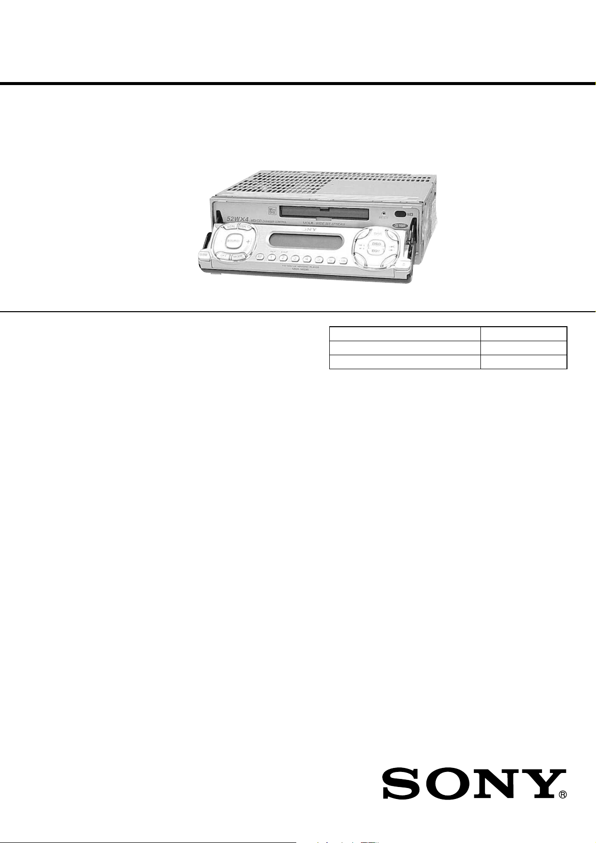
MDX-M690
MD Player section
Signal-to-noise ratio 90 dB
Frequency response 10 – 20,000 Hz
Wow and flutter Below measurable limit
Tuner section
FM
Tuning range 87.5 – 108.0 MHz
Aerial terminal External aerial connector
Intermediate frequency 10.7 MHz/450 kHz
Usable sensitivity 8 dBf
Selectivity 75 dB at 400 kHz
Signal-to-noise ratio 66 dB (stereo),
72 dB (mono)
Harmonic distortion at 1 kHz
0.6 % (stereo),
0.3 % (mono)
Separation 35 dB at 1 kHz
Frequency response 30 – 15,000 Hz
MW/LW
Tuning range MW: 531 – 1,602 kHz
LW: 153 – 279 kHz
Aerial terminal External aerial connector
Intermediate frequency 10.7 MHz/450 kHz
Sensitivity MW: 30 µV
LW: 40 µV
Power amplifier section
Outputs Speaker outputs
(sure seal connectors)
Speaker impedance 4 – 8 ohms
Maximum power output 52 W
× 4 (at 4 ohms)
General
Outputs Audio outp uts (front/re ar)
Subwoofer output (mono)
Power aerial relay control
lead
Power amplif ier co ntrol lead
Inputs Telephone ATT control lead
Illumination control lead
BUS control input
connector
BUS audio input connector
Remote controller input
connector
Aerial input connector
Loudness +8 dB at 100 Hz
+2 dB at 10 kHz
Power requirements 12 V DC car battery
(negative eart h )
Dimensions Approx. 178
× 50 × 182 mm
(w/h/d)
Mounting dimensions Approx. 182
× 53 × 160 mm
(w/h/d)
Mass Approx. 1.5 kg
Supplied accessories Parts for installation and
connections (1 set)
Front panel case (1)
Card remote commander
RM-X111
Tone controls Bass ±8 dB at 100 Hz
Treble ±8 dB at 10 kHz
Note
This unit cannot be connected to a digital preamplifier
or an equalizer.
Design and specifications are subject to change
without notice.
SERVICE MANUAL
Ver 1.0 2001.03
US and foreign patents licensed from Dolby Laboratories.
SPECIFICATIONS
AEP Model
UK Model
Model Name Using Similar Mechanism MDX-CA680
Base Mechanism Type MG-164MA-138
Optical Pick-up Name KMS-241C
9-870-294-11 Sony Corporation
2001C0500-1 Audio Entertainment Group
C 2001.3 General Engineering Dept.
FM/MW/LW MINI DISC PLAYER
Page 2

MDX-M690
TABLE OF CONTENTS
1. SERVICING NOTES............................................... 4
2. GENERAL
Location of Controls ....................................................... 5
3. DISASSEMBLY
3-1. Disassembly Flow ........................................................... 8
3-2. Cover ............................................................................... 9
3-3. Front Panel (Key) Assy ................................................... 9
3-4. Mechanism Deck (MG-164MA-138) ............................. 10
3-5. Motor Block Assy, Cam (R) Assy .................................. 10
3-6. Sub Panel Assy ................................................................ 11
3-7. MAIN Board ................................................................... 11
3-8. Heat Sink ......................................................................... 12
3-9. SERVO Board ................................................................. 12
3-10. MD Cover Assy............................................................... 13
3-11. Float Block ...................................................................... 13
3-12. Lo Motor Assy (Loading) (M903).................................. 14
3-13. Lever (LE23) Assy .......................................................... 14
3-14. Holder Assy ..................................................................... 15
3-15. Chucking Arm Assy ........................................................ 15
3-16. Optical Pick-up (KMS-241C) ......................................... 16
3-17. SL Motor Assy (Sled) (M902),
SP Motor Assy (Spindle) (M901)................................... 16
4. ASSEMBLY
4-1. Assembly Flow................................................................ 17
4-2. Motor Block Assy ........................................................... 18
4-3. Cam (R) Assy .................................................................. 18
4-4. Adjusting Phase of Motor Block Assy,
Cam (R) Assy .................................................................. 19
4-5. Phase Check .................................................................... 19
6. DIAGRAMS
6-1. Block Diagram – SERVO Section – ............................... 21
6-2. Block Diagram – TUNER Section – .............................. 22
6-3. Block Diagram – MAIN Section – ................................. 23
6-4. Block Diagram – DISPLAY/BUS CONTROL/
POWER SUPPLY Section – ........................................... 24
6-5. Note for Printed Wiring Boards and
Schematic Diagrams ....................................................... 25
6-6. Printed Wiring Boards – SERVO Section – ................... 27
6-7. Schematic Diagram – SERVO Section (1/2) –............... 28
6-8. Schematic Diagram – SERVO Section (2/2) –............... 29
6-9. Printed Wiring Board – MAIN Section (1/2) – .............. 30
6-10. Printed Wiring Boards – MAIN Section (2/2) – ............ 31
6-11. Schematic Diagram – MAIN Section (1/4) – ................. 32
6-12. Schematic Diagram – MAIN Section (2/4) – ................. 33
6-13. Schematic Diagram – MAIN Section (3/4) – ................. 34
6-14. Schematic Diagram – MAIN Section (4/4) – ................. 35
6-15. Printed Wiring Board – SUB MD Board –..................... 36
6-16. Schematic Diagram – SUB MD Board – ....................... 37
6-17. Printed Wiring Board – KEY Board –............................ 38
6-18. Schematic Diagram – KEY Board – .............................. 39
6-19. Printed Wiring Board – DISPLAY Board – ................... 40
6-20. Schematic Diagram – DISPLAY Board – ...................... 41
6-21. IC Pin Function Description ........................................... 49
7. EXPLODED VIEWS
7-1. Sub Panel Section............................................................ 61
7-2. Front Panel (DSPL) Section ........................................... 62
7-3. Front Panel (KEY) Section ............................................. 63
7-4. MAIN Board Section ...................................................... 64
7-5. Mechanism Deck Section-1 (MG-164MA-138) ............ 65
7-6. Mechanism Deck Section-2 (MG-164MA-138) ............ 66
5. ELECTRICAL ADJUSTMENTS
Test Mode........................................................................ 20
MD Section ..................................................................... 20
Tuner Section .................................................................. 20
8. ELECTRICAL PARTS LIST ............................... 67
2
Page 3
NOTES ON HANDLING THE OPTICAL PICK-UP
p
BLOCK OR BASE UNIT
The laser diode in the optical pick-up block may suffer electrostatic break-down because of the potential difference generated
by the charged electrostatic load, etc. on clothing and the human
body.
During repair, pay attention to electrostatic break-down and also
use the procedure in the printed matter which is included in the
repair parts.
The flexible board is easily damaged and should be handled with
care.
NOTES ON LASER DIODE EMISSION CHECK
Never look into the laser diode emission from right avove when
checking it for adustment. It is feared that you will lose your sight.
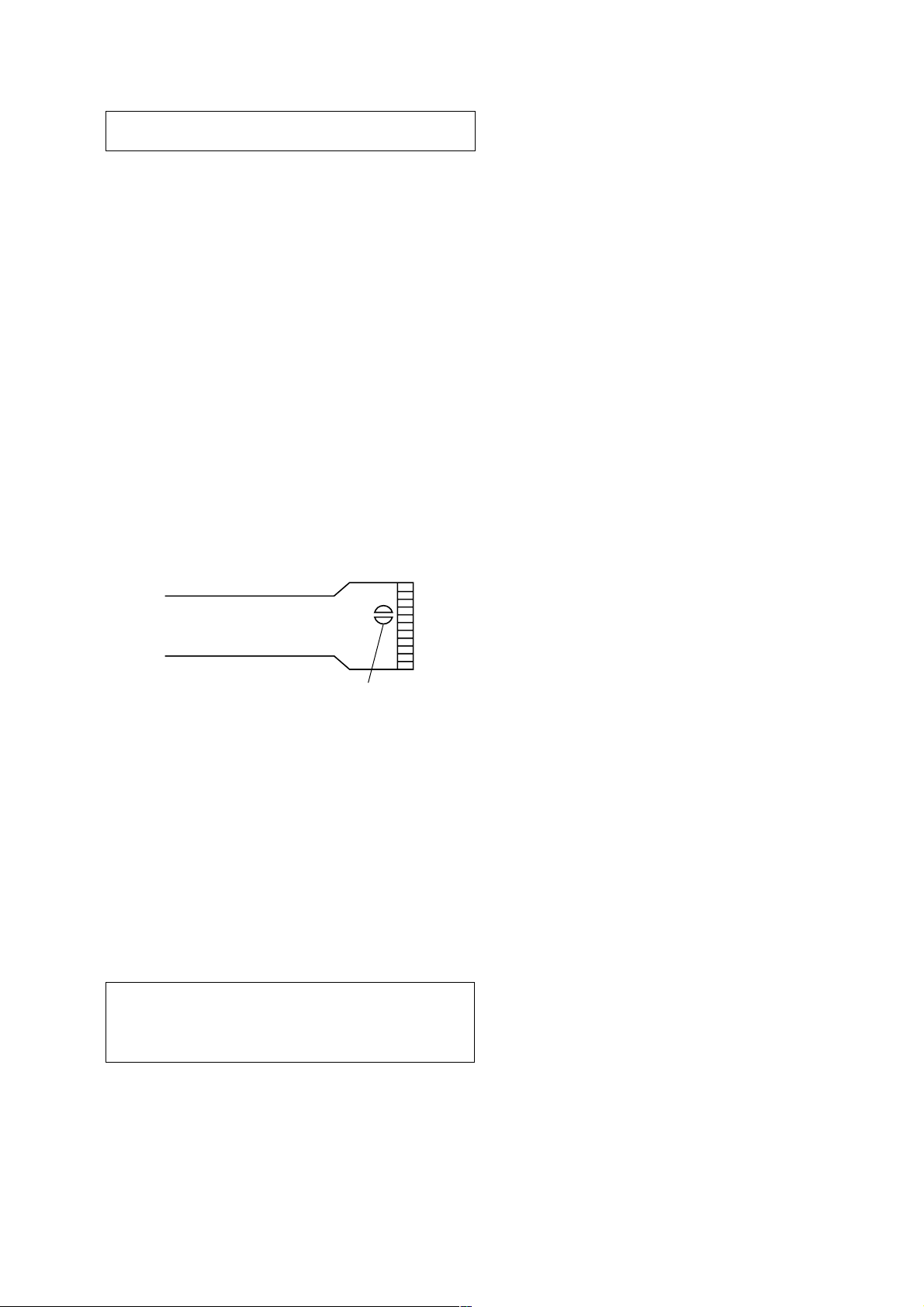
NOTES ON HANDLING THE OPTICAL PICK-UP BLOCK
(KMS-241C).
The laser diode in the optical pick-up block may suffer electrostatic break-down easily. When handling it, perform soldering
bridge to the laser-tap on the flexible board. Also perform measures against electrostatic break-down sufficiently before the operation. The flexible board is easily damaged and should be
handled with care.
MDX-M690
laser-ta
OPTICAL PICK-UP FLEXIBLE BOARD
Notes on chip component replacement
• Never reuse a disconnected chip component.
• Notice that the minus side of a tantalum capacitor may be dam-
aged by heat.
Flexible Circuit Board Repairing
• Keep the temperature of the soldering iron around 270 ˚C during repairing.
• Do not touch the soldering iron on the same conductor of the
circuit board (within 3 times).
• Be careful not to apply force on the conductor when soldering
or unsoldering.
CAUTION
Use of controls or adjustments or performance of procedures
other than those specified herein may result in hazardous radiation exposure.
SAFETY-RELATED COMPONENT WARNING!!
COMPONENTS IDENTIFIED BY MARK 0 OR DOTTED
LINE WITH MARK 0 ON THE SCHEMATIC DIAGRAMS
AND IN THE PARTS LIST ARE CRITICAL TO SAFE
OPERATION. REPLACE THESE COMPONENTS WITH
SONY PARTS WHOSE PART NUMBERS APPEAR AS
SHOWN IN THIS MANU AL OR IN SUPPLEMENTS PUBLISHED BY SONY.
3
Page 4
MDX-M690
m
SECTION 1
SERVICING NOTES
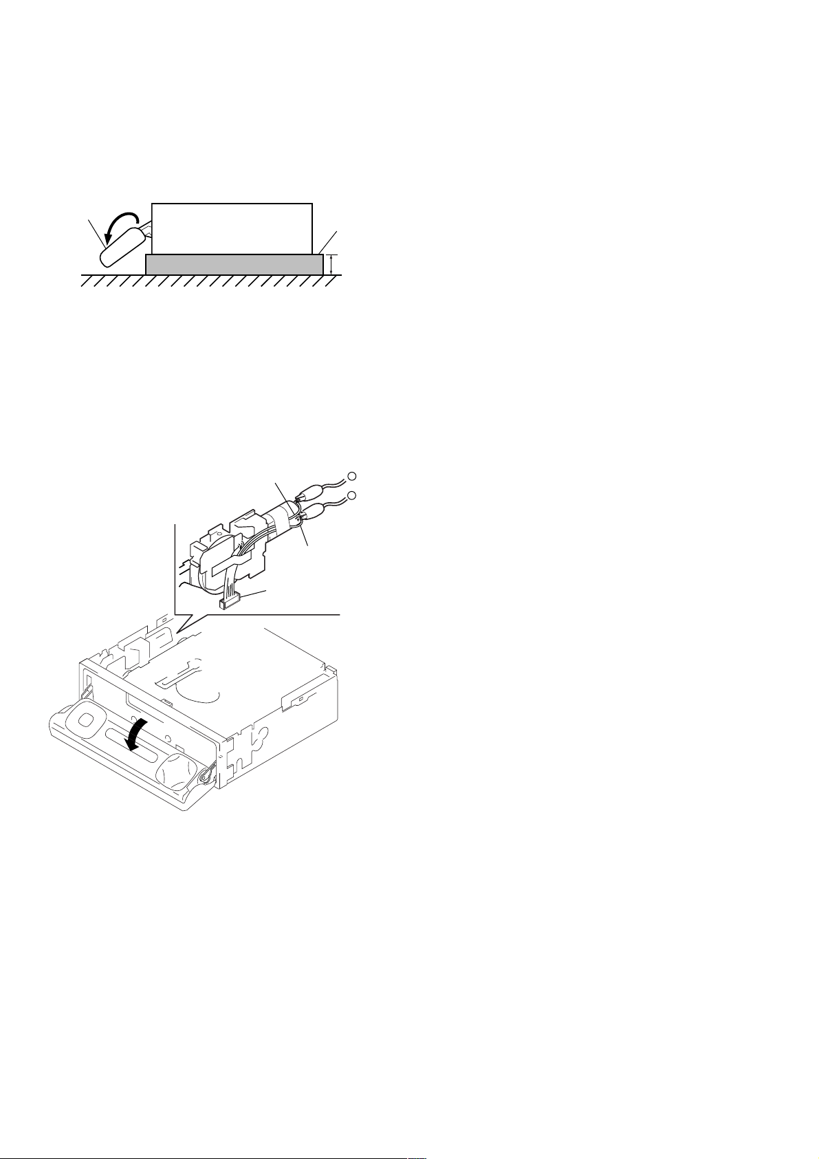
PRECAUTION ON OPEN/CLOSE FRONT PANEL
The front panel opens to the bottom of main unit.
In performing the repair, place the main unit on the base having
the height exceeding 1 cm.
front panel
MDX-M690
( SIDE VIEW)
Open the front panel by supplying the power through the following steps:
1. Disconnect the motor connector (CN602) from main board.
2. Supply the power to the motor.
Voltage : 9 V
Yellow wiring: MOTOR –
Black wiring : MOTOR +
yellow wiring
base
1c
–
+
DETACHING THE DISPLAY PANEL IN THE TEST MODE
In the normal mode, after pressing the [OPEN] key for two seconds to set the front panel in detaching position and detaching the
display panel is complete, the front panel closes automatically.
But in the test mode, the front panel opens automatically. (ref er to
page 20 for test mode)
black wiring
connector
(CN602)
4
Page 5
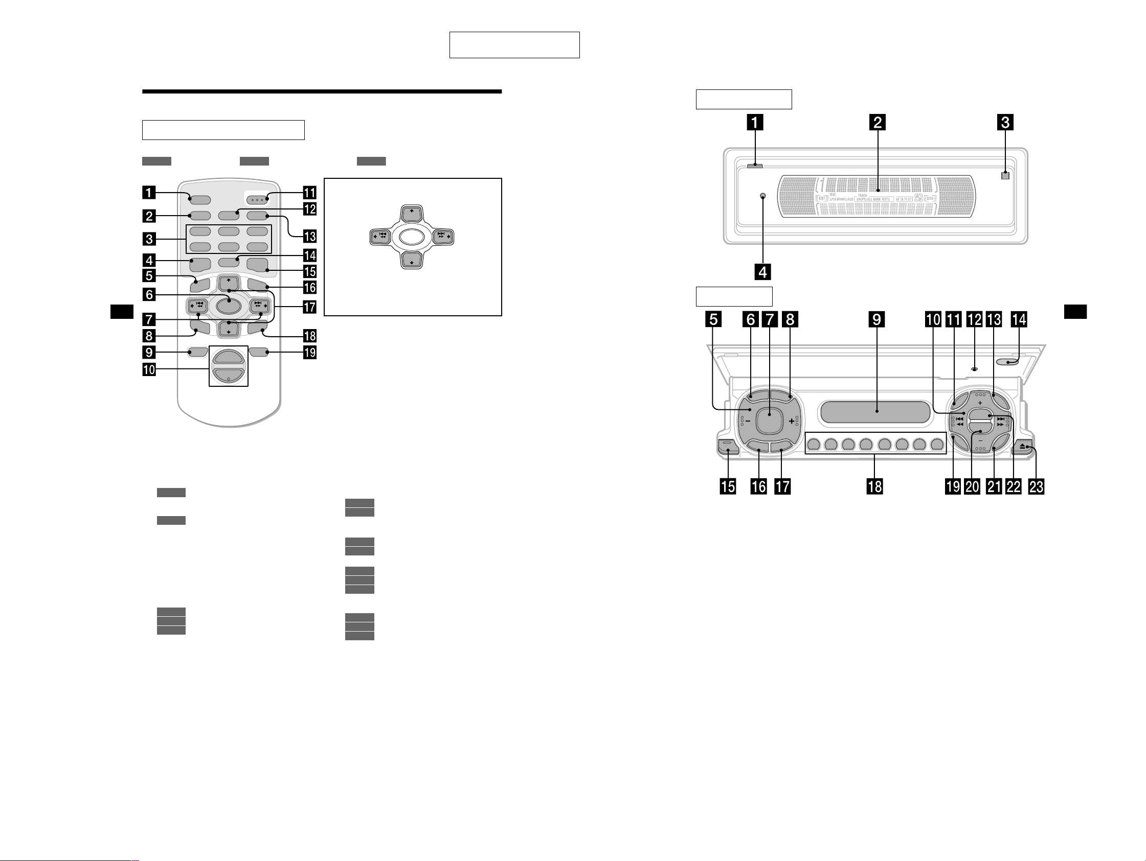
SECTION 2
5
The corresponding buttons of the unit
control the same functions as those on
the card remote commander.
a OPEN button 9, 11, 37
b Main display window
c qf Receptor for the card remote
commander
d qs Reset button 9
e Volume adjust buttons
f SCRL (scroll) button
g SOURCE button
h DSPL/PTY (display mode change/
programme type) button
i Sub display window
j DISC +/– (cursor up/down) buttons
SEEK –/+ (cursor left/right) buttons
k MENU button
m LIST button
o
CLOSE (front panel close) button
9, 11
p OFF (Stop/Power off) button*
q MODE button
r Number buttons
s SOUND button
t EQ7 button
u ENTER button
v DSO button
w Z (eject) button 11
Main display panel
Operation side
CLOSE
O
F
F
M
O
D
E
SOURCE
ENTER
SOUND
M
E
N
U
LIST
DISC
RESET
DISC
DSO
REP SHUF
EQ7
AF TA
123456
S
C
R
L
D
S
P
L
P
T
Y
GENERAL
Location of controls
Card remote commander RM-X111
Refer to the pages listed for details.
: During Playback : During radio reception : During menu mode
CD/MD
RADIO MENU
MDX-M690
This section is extracted from
instruction manual.
AF
2
5
MODE
+
DISC
SOURCE
–
DISC
+
VOL
OPEN/CLOSE
LIST
SEEK
ENTER
ATTOFF
SCRL
PTY
DSPL
REP SHUF
1
4
EQ7 DSO
MENU
–
SEEK
SOUND
–
a SCRL (scroll) button 12
b DSPL/PTY (display mode change/
programme type) button 12, 13, 17,
20, 25, 35
c Number buttons
CD/MD
(1) REP 12
(2) SHUF 12
RADIO
15, 16, 18, 19, 22, 24
d EQ7 button 26
e MENU button 10, 13, 14, 15, 19, 21,
23, 25, 26, 27, 28, 30, 31, 33, 34, 35
f SOURCE (Power on/Radio/CD/MD)
button 10, 11, 13, 15, 16, 19, 22, 26,
27, 29, 30, 31, 33, 35
g </, SEEK +/– buttons 10, 28, 29, 30,
31
11
CD/MD
16, 18, 22
RADIO
10, 13, 14, 15, 21, 23, 25, 26,
MENU
27, 28, 30, 31, 33, 34, 35
h SOUND button 28, 29, 30, 31
4
M (DISC)
(+): to select upwards
< (SEEK)
TA
3
6
+
(–): to select
leftwards/
.
In menu mode, the currently selectable button (s) of
these four are indicated with a “ v” in the display.
Note
If the unit is turned off by pressing (OFF) for 2
seconds, the unit cannot be operated with the card
remote commander unless (SOURCE) on the unit is
pressed, or a disc is inserted to activate the unit first.
Tip
Refer to “Replacing the lithium battery” for details on
how to replace the batter ies (page 36).
SEEK
(–): to select downwards
–
m (DISC)
+
DISC
SOURCE
–
DISC
+
SEEK
, (SEEK)
(+): to select
rightwards/
>
i OFF (Stop/Power off) button 11, 35
j VOL +/– buttons 19
k OPEN/CLOSE button 11, 37
l AF button 18, 19
m TA butto n 19
n MODE button
CD/MD
11, 13
RADIO
15, 16, 19, 22
o DSO button 27
p LIST button
CD/MD
RADIO
13, 14
17, 24
q M/m DISC +/– buttons
26, 27, 28, 30, 31, 33, 34, 35
r ENTER button
16, 17, 20, 22, 23, 24, 25
RADIO
10, 13, 14, 15, 19, 21, 23, 25,
MENU
CD/MD
14
RADIO
17, 20, 23, 24, 25
MENU
10, 13, 14, 15, 19, 21, 23, 25,
11, 14
CD/MD
26, 27, 30, 31, 33, 34, 35
s ATT button 33
55
Page 6
MDX-M690
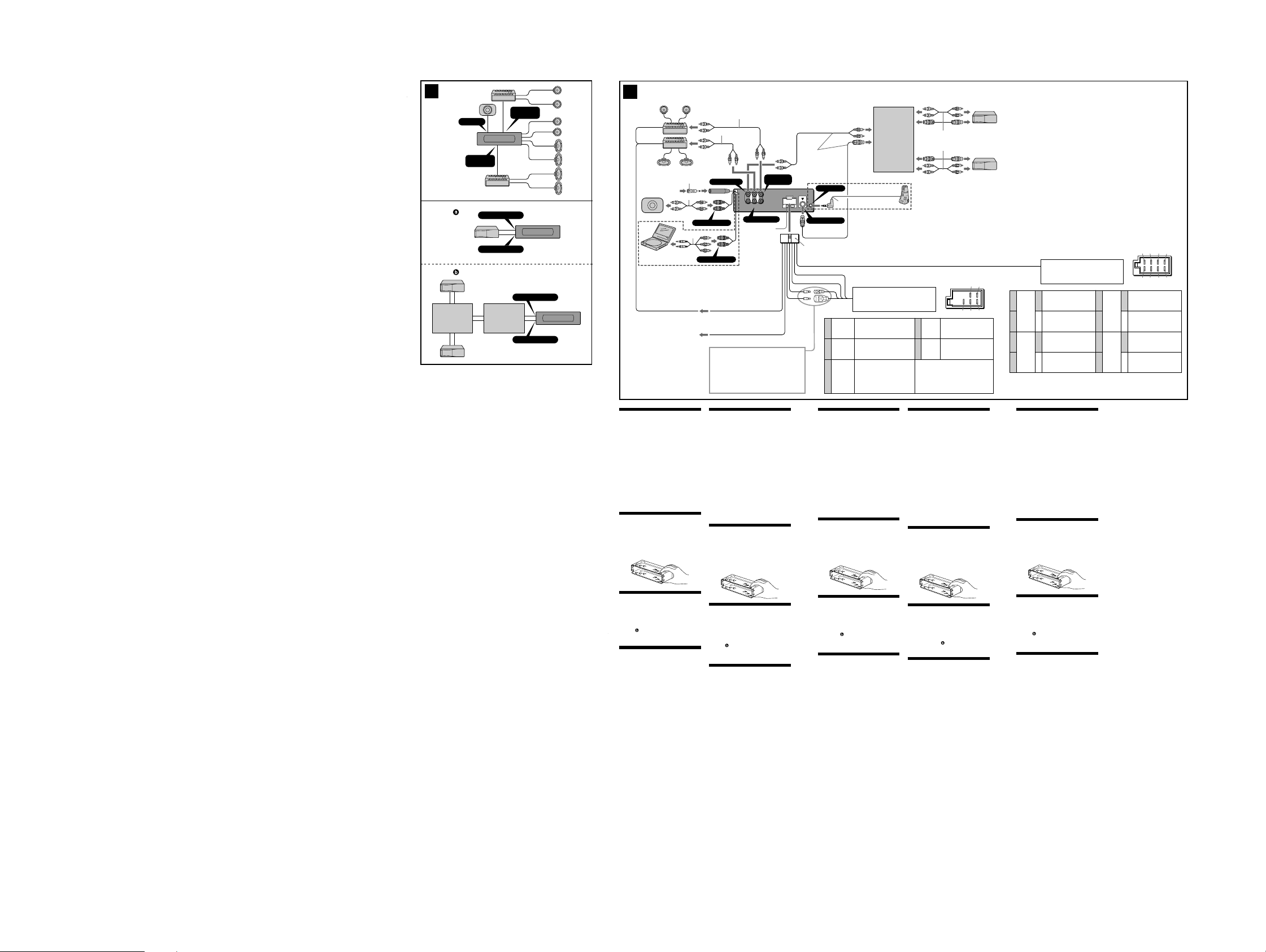
2 A
B
Source selector*
Signalquellenwähler*
Sélecteur de source*
Selettore di fonte*
Geluidsbronkiezer*
SUB OUT
AUDIO OUT
REAR
BUS AUDIO IN
BUS CONTROL IN
DAB tuner unit*
Syntoniseur DAB*
DAB-Tunereinheit*
DAB tuner*
Sintonizzatore DAB*
XT-100DAB
AUDIO OUT
FRONT
BUS AUDIO IN
BUS CONTROL IN
* not supplied
nicht mitgeliefert
non fournis
non in dotazione
niet bijgeleverd
3
from car aerial
von Autoantenne
de l’antenne de la voiture
dall’antenna dell’auto
van een auto-antenne
4
*
3
*
Max. supply current 0.3 A
max. Versorgungsstrom 0,3 A
Courant max. fourni 0,3 A
Alimentazione massima fornita 0,3 A
Max. voedingsstroom 0,3 A
*1Note for the aerial connecting
If your car aerial is an ISO (International Organisation for
Standardisation) type, use the supplied adaptor 6 to
connect it. First connect the car aerial to the supplied
adaptor, then connect it to the aerial jack of the master
unit.
2
*
RCA pin cord (not supplied)
3
*
CDX-M770 only
2
*
2
*
Supplied with XA-C30
Mit dem XA-C30 geliefert
Fourni avec le XA-C30
In dotazione con il modello
XA-C30
1
*
1
*
1
*
1
*
6
1
*
2
*
SUB OUT (MONO)
5
*
BUS AUDIO IN
L
R
AUDIO OUT
AUDIO OUT
BUS
FRONT
REAR
AUDIO
AUDIO OUT REAR
Fuse (10 A)
Sicherung (10 A)
Fusible (10 A)
Fusibile (10 A)
Zekering (10 A)
AUDIO OUT
FRONT
Geleverd met de XA-C30
REMOTE IN
BUS CONTROL IN
8
*
Source selector (not
supplied)
Signalquellenwähler
(nicht mitgeliefert)
Sélecteur de source
(non fourni)
Selettore di fonte
(non in dotazione)
Geluidsbronkiezer
(niet bijgeleverd)
XA-C30
Supplied with the CD/MD changer
Mit dem CD/MD-Wechsler geliefert
Fourni avec le changeur de CD/MD
In dotazione con il cambia CD/MD
Geleverd met de CD/MD-wisselaar
7
*
8
6
AUX-IN (AUDIO)
*
Blue/white striped
Blau-weiß gestreift
A
AMP REM
B
ATT
Rayé bleu/blanc
A strisce blu e bianche
Blauw/wit gestreept
Light blue
Hellblau
Bleu ciel
Azzurro
Hemelsblauw
See “Power Connection diagram” on the reverse side for
details.
Näheres dazu finden Sie im “Stromanschlußdiagramm”.
Blättern Sie dazu bitte um.
Schéma de connexion d’alimentation
Voir le “
pour plus de détails.
Per ulteriori informazioni, vedere “Diagramma dei
collegamenti di alimentazione” che si trova sul retro.
Zie “Voedingsaansluitschema” op de achterkant voor
meer details.
” au verso
4
5
Orange/White
Orange-weiß
Rayé orange/
6
Yellow
Gelb
Jaune
Giallo
Geel
Blue
Blau
Bleu
Blu
Blauw
gestreift
blanc
Arancione/
bianco
Oranje/wit
from the car’s power connector
vom Stromanschluß des Fahrzeugs
du connecteur d’alimentation de la voiture
dal connettore di alimentazione dell’auto
van de autovoedingsstekker
continuous power supply
permanente Stromversorgung
alimentation continue
alimentazione continua
continu voeding
power aerial control
Motorantenne
antenne électrique
comando dell’antenna elettrica
automatische antenne
switched illumination power supply
geschaltete
Beleuchtungsstromversorgung
alimentation de l’éclairage
commuté
alimentazione a illuminazione
commutata
geschakelde verlichting
stroomvoorziening
Red
Rot
7
Rouge
Rosso
Rood
Black
Schwarz
8
Noir
Nero
Zwart
Positions 1, 2 and 3 do not have pins.
An Position 1, 2 und 3 befinden sich keine Stifte.
Les positions 1, 2 et 3 ne comportent pas de
broches.
Le posizioni 1, 2 e 3 non hanno piedini.
De posities 1, 2 en 3 hebben geen pins.
57
4
68
switched power supply
geschaltete Stromversorgung
alimentation commutée
alimentazione commutata
geschakelde voeding
earth
Masse
masse
terra
aarding
4
*
Auxiliary equipment such as portable DVD player DVP-FX1
(not supplied)
5
*
supplied with the auxialiry equipment
6
*
Be sure to match the colour-coded code for audio to the
appropriate jacks from the unit.
7
*
CDX-M670,MDX-M690 only
8
*
Insert with the cord upwards
1
*
Hinweis zum Anschließen der Antenne
Wenn Ihre Fahrzeugantenne der ISO-Norm (ISO =
International Organization for Standardization Internationale Normungsgemeinschaft) entspricht,
schließen Sie sie mit Hilfe des mitgelieferten Adapters 6
an. Verbinden Sie zuerst die Fahrzeugantenne mit dem
mitgelieferten Adapter, und verbinden Sie diesen dann mit
der Antennenbuchse des Hauptgeräts.
2
*
Cinchkabel (nicht mitgeliefert)
3
*
nur CDX-M770
4
*
Zusätzliche Geräte wie z. B. der tragbare DVD-Player DVPFX1
5
*
mit den Zusatzgeräten mitgeliefert
6
*
Achten Sie darauf, das farbcodierte Audiokabel mit den
richtigen Buchsen am Gerät zu verbinden.
7
*
nur CDX-M670 und MDX-M690
8
Mit dem kabel nach oben einsetzen!
*
1
*
Remarque sur le raccordement de l’antenne
Si votre antenne de voiture est de type ISO (organisation
internationale de normalisation), utilisez l’adaptateur
fourni 6 pour la raccorder. Raccordez d’abord l’antenne de
voiture à l’adaptateur fourni et, ensuite, à la prise
d’antenne de l’appareil principal.
2
*
Cordon à broche RCA (non fourni)
3
*
CDX-M770 uniquement
4
Equipement auxiliaire en option tel que le lecteur portable
*
DVD DVP-FX1
5
*
fourni avec l’équipement auxiliaire
6
*
Veillez à faire correspondre le code couleur audio aux
fiches de l’appareil.
7
*
CDX-M670,MDX-M690 uniquement
8
*
Insérez avec le câble vers le haut
1
2
3
4
Negative polarity positions 2, 4, 6, and 8 have striped cords.
An den negativ gepolten Positionen (2, 4, 6 und 8) befinden sich gestreifte Adern.
Les positions de polarité négative 2, 4, 6 et 8 sont dotées de cordons rayés.
Le posizioni a polarità negativa 2, 4, 6 e 8 hanno cavi rigati.
De negatieve posities 2, 4, 6 en 8 hebben gestreepte kabels.
from the car’s speaker connector
vom Lautsprecheranschluß des Fahrzeugs
du connecteur de haut-parleur de la voiture
dal connettore del diffusore dell’auto
van de autoluidsprekerstekker
Lautsprecher hinten rechts
haut-parleur, arrière, droit
+
Diffusore, posteriore, destro
Purple
Luidspreker, achter, rechts
Violett
Mauve
Viola
Lautsprecher hinten rechts
Paars
haut-parleur, arrière, droit
–
Diffusore, posteriore, destro
Luidspreker, achter, rechts
Lautsprecher vorne rechts
haut-parleur, avant, droit
+
Diffusore, anteriore, destro
Grey
Luidspreker, voor, rechts
Grau
Gris
Grigio
Lautsprecher vorne rechts
Grijs
haut-parleur, avant, droit
–
Diffusore, anteriore, destro
Luidspreker, voor, rechts
Speaker, Rear, Right
Speaker, Rear, Right
Speaker, Front, Right
Speaker, Front, Right
*1Nota per il collegamento dell’antenna
Se la vostra antenna della macchina è di tipo ISO
(International Organization Standardization), utilizzare
l’adattatore 6 in dotazione per collegarla. Collegare prima
l’antenna della macchina all’adattatore in dotazione,
quindi collegarla alla presa dell’antenna dell’apparecchio
principale.
2
*
Cavo a piedini RCA (non in dotazione)
3
*
solo CDX-M770
4
Apparecchio opzionale ausiliario quale il lettore DVD
*
portatile DVP-FX1
5
*
in dotazione con l’apparecchio ausiliario
6
*
Assicurarsi che i cavi differenziati in base al colore per l’audio
corrispondano alle prese appropriate dell’apparecchio.
*7solo CDX-M670,MDX-M690
8
*
Inserire con il cavo rivolto verso l’alto
1
*
Opmerking bij de antenne-aansluiting
Indien uw wagen is uitgerust met een antenne van het
type ISO (International Organisation for Standardization),
moet u die aansluiten met behulp van de meegeleverde
adaptor 6. Sluit eerst de auto-antenne aan op de
meegeleverde adaptor en vervolgens de antennestekker op
het hoofdtoestel.
2
*
Tulpstekkersnoer (niet bijgeleverd)
3
*
alleen CDX-M770
4
*
Los verkrijgbare apparatuur zoals de draagbare DVDspeler DVP-FX1
5
*
meegeleverd met de los verkrijgbare apparatuur
6
*
Zorg ervoor dat de kleurcode voor audio overeenkomt met
de betreffende aansluitingen op het toestel.
7
*
alleen CDX-M670, MDX-M690
8
*
Inbrengen met het snoer naar boven
13 57
24 68
Speaker, Front, Left
White
Weiß
Blanc
Bianco
Green
Verde
Groen
Wit
Grün
Vert
Lautsprecher vorne links
haut-parleur, avant, gauche
+
Diffusore, anteriore, sinistro
Luidspreker, voor, links
Speaker, Front, Left
Lautsprecher vorne links
haut-parleur, avant, gauche
–
Diffusore, anteriore, sinistro
Luidspreker, voor, links
Speaker, Rear, Left
Lautsprecher hinten links
haut-parleur, arrière, gauche
+
Diffusore, posteriore, sinistro
Luidspreker, achter, links
Speaker, Rear, Left
Lautsprecher hinten links
haut-parleur, arrière, gauche
–
Diffusore, posteriore, sinistro
Luidspreker, achter, links
5
6
7
8
Cautions
•This unit is designed for negative earth 12 V DC
operation only.
•Do not get the wires under a screw, or caught in
moving parts (e.g. seat railing).
•Before making connections, turn the car ignition
off to avoid short circuits.
•Connect the power connecting cord 8 to the unit
and speakers before connecting it to the auxiliary
power connector.
•Run all earth wires to a common earth point.
•Be sure to insulate any loose unconnected wires
with electrical tape for safety.
Notes on the power supply cord (yellow)
•When connecting this unit in combination with
other stereo components, the connected car
circuit’s rating must be higher than the sum of
each component’s fuse.
•When no car circuits are rated high enough,
connect the unit directly to the battery.
Parts list (1)
The numbers in the list are keyed to those in the
instructions.
For the use of release key qs, see the supplied
operating instructions.
Caution
Handle the bracket 1 carefully to avoid injuring
your fingers.
Connection example (2)
Notes (2-A)
• Be sure to connect the earth cord before
connecting the amplifier.
• If you connect an optional power amplifier and do
not use the built-in amplifier, the beep sound will
be deactivated.
Tip (2-B-
)
For connecting two or more CD/MD changers, the
source selector XA-C30 (optional) is necessary.
Connection diagram (3)
A
To AMP REMOTE IN of an optional power
amplifier
This connection is only for amplifiers. Connecting
any other system may damage the unit.
B
To the interface cable of a car telephone
Warning
If you have a power aerial without a relay box,
connecting this unit with the supplied power
connecting cord 8 may damage the aerial.
Notes on the control leads
• The power aerial control lead (blue) supplies +12 V
DC when you turn on the tuner or when you
activate the AF (Alternative Frequency), TA (Traffic
Announcement) function.
• When your car has built-in FM/MW/LW aerial in
the rear/side glass, connect the power aerial
control lead (blue) or the accessory power input
lead (red) to the power terminal of the existing
aerial booster. For details, consult your dealer.
• A power aerial without a relay box cannot be used
with this unit.
Memory hold connection
When the yellow power input lead is connected,
power will always be supplied to the memory circuit
even when the ignition switch is turned off.
Notes on speaker connection
• Before connecting the speakers, turn the unit off.
• Use speakers with an impedance of 4 to 8 ohms,
and with adequate power handling capacities to
avoid its damage.
• Do not connect the speaker terminals to the car
chassis, or connect the terminals of the right
speakers with those of the left speaker.
• Do not connect the earth lead of this unit to the
negative (–) terminal of the speaker.
• Do not attempt to connect the speakers in parallel.
• Connect only passive speakers. Connecting active
speakers (with built-in amplifiers) to the speaker
terminals may damage the unit.
• To avoid a malfunction, do not use the built-in
speaker wires installed in your car if the unit shares
a common negative (–) lead for the right and left
speakers.
• Do not connect the unit’s speaker cords to each
other.
Vorsicht
•Dieses Gerät ist ausschließlich für den Betrieb bei 12
V Gleichstrom (negative Erdung) bestimmt.
•Achten Sie darauf, daß die Kabel nicht unter einer
Schraube oder zwischen beweglichen Teilen wie z.
B. in einer Sitzschiene eingeklemmt werden.
•Schalten Sie, bevor Sie irgendwelche Anschlüsse
vornehmen, die Zündung des Fahrzeugs aus, um
Kurzschlüsse zu vermeiden.
•Verbinden Sie das Stromversorgungskabel 8 mit
dem Gerät und den Lautsprechern, bevor Sie es mit
dem Hilfsstromanschluß verbinden.
•Schließen Sie alle Erdungskabel an einen
gemeinsamen Massepunkt an.
•Aus Sicherheitsgründen müssen alle losen, nicht
angeschlossenen Drähte mit Isolierband abisoliert
werden.
Hinweise zum Stromversorgungskabel (gelb)
•Wenn Sie dieses Gerät zusammen mit anderen
Stereokomponenten anschließen, muß der
Autostromkreis, an den die Geräte angeschlossen
sind, eine höhere Leistung aufweisen als die Summe
der Sicherungen der einzelnen Komponenten.
•Wenn kein Autostromkreis eine so hohe Leistung
aufweist, schließen Sie das Gerät direkt an die
Batterie an.
Teileliste (1)
Die Nummern in der Liste sind dieselben wie im
Erläuterungstext.
Wie Sie den Löseschlüssel qs verwenden, schlagen
Sie bitte in der mitgelieferten Bedienungsanleitung
nach.
Vorsicht
Seien Sie beim Umgang mit der Halterung 1
vorsichtig, damit Sie sich nicht die Hände verletzen.
Anschlu§beispiel (2)
Hinweise (2-A)
• Schließen Sie unbedingt zuerst das Massekabel an,
bevor Sie den Verstärker anschließen.
• Wenn Sie einen gesondert erhältlichen
Endverstärker anschließen und den integrierten
Verstärker nicht benutzen, wird der Signalton
deaktiviert.
Tip (2-B- )
Zum Anschließen von zwei oder mehr CD/MDWechslern wird der gesondert erhältliche
Signalquellenwähler XA-C30 benötigt.
Anschlu§diagramm (3)
A
An AMP REMOTE IN des gesondert erhältlichen
Endverstärkers
Dieser Anschluß ist ausschließlich für Verstärker
gedacht. Schließen Sie nichts anderes daran an.
Andernfalls kann das Gerät beschädigt werden.
B
An Schnittstellenkabel eines Autotelefons
Warnung
Wenn Sie eine Motorantenne ohne Relaiskästchen
verwenden, kann durch Anschließen dieses Geräts
mit dem mitgelieferten Stromversorgungskabel 8
die Antenne beschädigt werden.
Hinweise zu den Steuerleitungen
• Die Motorantennen-Steuerleitung (blau) liefert
+ 12 V Gleichstrom, wenn Sie den Tuner einschalten
oder die AF- (Alternativfrequenzsuche) oder die TAFunktion (Verkehrsdurchsagen) aktivieren.
• Wenn das Fahrzeug mit einer in der Heck-/
Seitenfensterscheibe integrierten FM (UKW)/MW/
LW-Antenne ausgestattet ist, schließen Sie die
Motorantennen-Steuerleitung (blau) oder die
Zubehörstromversorgungsleitung (rot) an den
Stromversorgungsanschluß des vorhandenen
Antennenverstärkers an. Näheres dazu erfahren Sie
bei Ihrem Händler.
• Es kann nur eine Motorantenne mit Relaiskästchen
angeschlossen werden.
Stromversorgung des Speichers
Wenn das gelbe Stromversorgungskabel
angeschlossen ist, wird der Speicher stets (auch bei
ausgeschalteter Zündung) mit Strom versorgt.
Hinweise zum Lautsprecheranschluß
• Schalten Sie das Gerät aus, bevor Sie die
Lautsprecher anschließen.
• Verwenden Sie Lautsprecher mit einer Impedanz
zwischen 4 und 8 Ohm und ausreichender
Belastbarkeit. Ansonsten können die Lautsprecher
beschädigt werden.
• Verbinden Sie die Lautsprecheranschlüsse nicht mit
dem Wagenchassis, und verbinden Sie auch nicht die
Anschlüsse des rechten mit denen des linken
Lautsprechers.
• Verbinden Sie die Masseleitung dieses Geräts nicht
mit dem negativen (–) Lautsprecheranschluß.
• Versuchen Sie nicht, Lautsprecher parallel
anzuschließen.
• An die Lautsprecheranschlüsse dieses Geräts dürfen
nur Passivlautsprecher angeschlossen werden.
Schließen Sie keine Aktivlautsprecher (Lautsprecher
mit eingebauten Verstärkern) an, da diese sonst
beschädigt werden können.
• Um Fehlfunktionen zu vermeiden, verwenden Sie
nicht die im Fahrzeug installierten, integrierten
Lautsprecherleitungen, wenn am Ende eine
gemeinsame negative (–) Leitung für den rechten
und den linken Lautsprecher verwendet wird.
• Verbinden Sie nicht die Lautsprecherkabel des
Geräts miteinander.
Prcautions
•Cet appareil est conçu pour fonctionner sur
courant continu de 12 V avec masse négative.
•Evitez de fixer des vis sur les câbles ou de coincer
ceux-ci dans des pièces mobiles (par exemple,
armature de siège).
•Avant d’effectuer des raccordements, éteignez le
moteur pour éviter les courts-circuits.
•Branchez le cordon d’alimention 8 sur l’appareil
et les haut-parleurs avant de le brancher sur le
connecteur d’alimentation auxiliaire.
•Rassemblez tous les fils de terre en un point de
masse commun.
•Veillez à isoler avec du chatterton tout fil lâche
non raccordé.
Remarques sur le cordon d’alimentation (jaune)
•Lorsque cet appareil est raccordé à d’autres
éléments stéréo, la valeur nominale des circuits de
la voiture raccordée doit être supérieure à la
somme des fusibles de chaque élément.
•Si aucun circuit de la voiture n’est assez puissant,
raccordez directement l’appareil à la batterie.
Liste des composants (1)
Les numéros de l’illustration correspondent à ceux
des instructions.
Pour l’utilisation de la clé de déblocage qs,
reportez-vous au mode d’emploi.
Attention
Manipulez précautionneusement le support 1
pour éviter de vous blesser aux doigts.
Exemple de raccordement (2)
Remarques (2-A)
• Raccordez d’abord le fil de masse avant de
raccorder l’amplificateur.
• Si vous raccordez un amplificateur de puissance
indépendant et que vous n’utilisez pas
l’amplificateur intégré, le bip sonore est désactivé.
Conseil (2-B-
)
Dans le cas du raccordement de deux changeurs de
CD/MD ou plus, le sélecteur de source XA-C30 (en
option) est indispensable.
Schma de raccordement (3)
A
Au niveau du AMP REMOTE IN d’un
amplificateur de puissance facultatif
Ce raccordement existe seulement pour les
amplificateurs. Le raccordement à tout autre
système peut endommager l’appareil.
B
Vers le cordon de liaison d’un téléphone de
voiture
Avertissement
Si vous disposez d’une antenne électrique sans
boîtier de relais, le branchement de cet appareil au
moyen du cordon d’alimentation fourni 8 risque
d’endommager l’antenne.
Remarques sur les fils de contrôle
• Le fil de commande (bleu) de l’antenne électrique
assure une alimentation de +12 V CC lorsque vous
mettez le syntoniseur sous tension ou lorsque vous
activez la fonction AF (fréquence secondaire) ou
TA (informations routières).
• Lorsque votre voiture est équipée d’une antenne
FM/MW/LW intégrée dans la vitre arrière/latérale,
raccordez la sortie de commande de l’antenne
(bleu) ou l’entrée d’alimentation des accessoires
(rouge) au bornier de l’amplificateur d’antenne
existant. Pour plus de détails, consultez votre
revendeur.
• Une antenne électrique sans boitier de relais ne
peut pas être utilisée avec cet appareil.
Raccordement pour la conservation de la mémoire
Lorsque le fil d’entrée d’alimentation jaune est
raccordé, le circuit de la mémoire est alimenté en
permanence même si la clé de contact est sur la
position d’arrêt.
Remarques sur le raccordement des haut-parleurs
• Avant de raccorder les haut-parleurs, mettez
l’appareil hors tension.
• Utilisez des haut-parleurs ayant une impédance de
4 à 8 ohms avec une capacité de manipulation
adéquate pour éviter de les endommager.
• Ne raccordez pas les bornes du système de hautparleurs au châssis de la voiture et ne raccordez
pas les bornes du haut-parleur droit à celles du
haut-parleur gauche.
• Ne raccordez pas le câble de masse de cet appareil
à la borne négative (–) de l’enceinte.
• N’essayez pas de raccorder les haut-parleurs en
parallèle.
• Raccordez uniquement des haut-parleurs passifs.
Le raccordement de haut-parleurs actifs (avec
amplificateurs intégrés) aux bornes des hautparleurs peut endommager l’appareil.
• Pour éviter tout dysfonctionnement, n’utilisez pas
les fils des haut-parleurs intégrés installés dans
votre voiture si l’appareil partage un fil négatif
commun (–) pour les haut-parleurs droit et gauche.
• Ne raccordez pas entre eux les cordons des hautparleurs de l’appareil.
Attenzione
•Questo apparecchio è stato progettato per l’uso solo
a 12 V CC con massa negativa.
•Evitare che i cavi rimangano bloccati da una vite o
incastrati nelle parti mobili (ad esempio nelle guide
scorrevoli dei sedili).
•Prima di effettuare i collegamenti, spegnere il
motore dell’automobile onde evitare di causare
cortocircuiti.
•Collegare il cavo di collegamento dell’alimentazione
8 all’apparecchio e ai diffusori prima di collegarlo
al connettore di alimentazione ausiliare.
•Portare tutti i cavi di massa a un punto di massa
comune.
•Per sicurezza, assicurarsi di isolare qualsiasi cavo
non collegato mediante apposito nastro.
Note sul cavo di alimentazione (giallo)
•Se questo apparecchio viene collegato con altri
componenti stereo, la potenza nominale dei circuiti
dell’automobile deve essere superiore a quella
prodotta dalla somma dei fusibili di ciascun
componente.
•Se la potenza nominale dei circuiti dell’automobile
non è sufficiente, collegare l’apparecchio
direttamente alla batteria.
Elenco dei componenti (1)
I numeri nella lista corrispondono a quelli riportati
nelle istruzioni.
Per informazioni sull’utilizzo del tasto di rilascio
qs, vedere le istruzioni per l’uso in dotazione.
Attenzione
Maneggiare la staffa 1 con cautela per evitare di
ferirsi le mani.
Esempi di collegamento (2)
Note (2-A)
• Assicurarsi di collegare il cavo di terra prima di
collegare l’apparecchio all’amplificatore.
• Se si collega un amplificatore di potenza opzionale
e non si utilizza l’amplificatore incorporato, il
segnale acustico verrà disattivato.
Suggerimento (2-B-
Per collegare due o più cambia CD/MD, si deve
utilizzare il selettore di fonte XA-C30 (opzionale).
Schema di collegamento (3)
A
B
Avvertenza
Quando si collega l’apparecchio con il cavo di
alimentazione in dotazione 8, si potrebbe
danneggiare l’antenna elettrica se questa non ha la
scatola di relè.
Note sui cavi di controllo
• Il cavo di controllo dell’antenna elettrica (blu)
fornisce corrente continua +12 V CC quando si
accende il sintonizzatore o quando si attiva la
funzione AF (frequenza alternativa) o TA
(notiziario sul traffico).
• Se l’automobile è dotata di antenna FM/MW/LW
incorporata nel vetro posteriore/laterale, collegare il
cavo (blu) di controllo dell’antenna elettrica o il cavo
(rosso) di ingresso dell’alimentazione opzionale al
terminale di alimentazione del preamplificatore
dell’antenna esistente. Per ulteriori informazioni,
consultare il proprio fornitore.
• Non è possibile usare un’antenna elettrica senza
scatola a relè con questo apparecchio.
Collegamento per la conservazione della memoria
Quando il cavo di ingresso alimentazione giallo è
collegato, viene sempre fornita alimentazione al
circuito di memoria anche quando la chiavetta a
accensione è spenta.
Note sul collegamento dei diffusori
• Prima di collegare i diffusori spegnere
l’apparecchio.
• Usare diffusori di impedenza compresa tra 4 e 8
ohm e con capacità di potenza adeguata,
altrimenti i diffusori potrebbero venir danneggiati.
• Non collegare i terminali del sistema diffusori al
telaio dell’auto e non collegare i terminali del
diffusore destro a quelli del diffusore sinistro.
• Non collegare il cavo di terra di questo
apparecchio al terminale negativo (–) del diffusore.
• Non collegare i diffusori in parallelo.
• Non collegare alcun diffusore attivo (con
amplificatore incorporato) ai terminali dei diffusori
dell’apparecchio perché si potrebbero danneggiare
i diffusori attivi. Assicurarsi di collegare diffusori
passivi a questi terminali.
• Per evitare problemi di funzionamento, non
utilizzare i cavi dei diffusori incorporati installati
nell’automobile se il terminale dell’apparecchio
condivide un cavo comune negativo (–) per i
diffusori destro e sinistro.
• Non collegare fra loro i cavi dei diffusori
dell’apparecchio.
)
A AMP REMOTE IN di un amplificatore di
potenza opzionale
Questo collegamento è riservato esclusivamente
agli amplificatori. Non collegare un tipo di
sistema diverso onde evitare di causare danni
all’apparecchio.
Al cavo interfaccia di un telefono per auto
Let op!
•Dit apparaat is ontworpen voor gebruik op
gelijkstroom van een 12 Volts auto-accu, negatief
geaard.
•Zorg ervoor dat de draden niet onder een schroef of
tussen bewegende onderdelen (b.v. zetelrail)
terechtkomen.
•Alvorens aansluitingen te verrichten moet u het
contact afzetten om kortsluiting te vermijden.
•Sluit het netsnoer 8 aan op het toestel en de
luidsprekers vooraleer u het op de
hulpvoedingsaansluiting aansluit.
•Sluit alle aarddraden op een gemeenschappelijk
aardpunt aan.
•Voorzie niet aangesloten draden om
veiligheidsredenen altijd van isolatietape.
Opmerkingen bij de voedingskabel (geel)
•Wanneer u dit toestel aansluit samen met andere
componenten, moet het vermogen van de aangesloten
autostroomkring groter zijn dan de som van de
zekeringen van elke component afzonderlijk.
•Wanneer het vermogen ontoereikend is, moet u het
toestel rechtstreeks aansluiten op de batterij.
Onderdelenlijst ( 1)
De nummers in de afbeelding verwijzen naar die in
de montage-aanwijzingen.
Raadpleeg de meegeleverde gebruiksaanwijzing om
de speciale sleutel te bedienen qs.
Voorzichtig
Houd de beugel 1 voorzichtig vast zodat u uw
vingers niet verwondt.
Voorbeeldaansluitingen ( 2)
Opmerkingen (2-A)
• Sluit eerst de massakabel aan alvorens de
versterker aan te sluiten.
• Als u een los verkrijgbare vermogensversterker
aansluit en de ingebouwde versterker niet
gebruikt, is de pieptoon uitgeschakeld.
Tip (2-B-
)
Om twee of meer CD/MD-wisselaars aan te sluiten,
hebt u de geluidsbronkiezer XA-C30 (optioneel)
nodig.
Aansluitschema (3)
A
Naar AMP REMOTE IN van een los verkrijgbare
vermogensversterker
Deze aansluiting is alleen bedoeld voor
versterkers. Door een ander systeem aan te sluiten
kan het toestel worden beschadigd.
B
Naar het interface-snoer van een autotelefoon
Opgelet
Indien u een elektrische antenne heeft zonder
relaiskast, kan het aansluiten van deze eenheid met
het bijgeleverde netsnoer 8 de antenne beschadigen.
Opmerking betreffende de aansluitsnoeren
• De voedingskabel (blauw) van de elektrisch
bediende antenne levert +12V gelijkstroom
wanneer u de tuner aanschakelt of de functie AF
(Alternative Frequency) of TA (Traffic
Announcement) activeert.
• Wanneer uw auto is uitgerust met een FM/MW/
LW-antenne in de achterruit/voorruit, moet u de
antennevoedingskabel (blauw) of de
hulpvoedingskabel (rood) aansluiten op de
voedingsingang van de bestaande
antenneversterker. Raadpleeg uw dealer voor
meer details.
• Met dit apparaat is het niet mogelijk een
automatische antenne zonder relaishuis te
gebruiken.
Instandhouden van het geheugen
Zolang de gele stroomdraad is aangesloten, blijft de
stroomvoorziening van het geheugen intact, ook
wanneer het contact van de auto wordt
uitgeschakeld.
Opmerkingen betreffende het aansluiten van de
luidsprekers
• Zorg dat het apparaat is uitgeschakeld, alvorens de
luidsprekers aan te sluiten.
• Gebruik luidsprekers met een impedantie van 4 tot
8 Ohm en let op dat die het vermogen van de
versterker kunnen verwerken. Als dit wordt
verzuimd, kunnen de luidsprekers ernstig
beschadigd raken.
• Verbind in geen geval de aansluitingen van de
luidsprekers met het chassis van de auto en sluit de
aansluitingen van de rechter en linker luidspreker
niet op elkaar aan.
• Verbind de massakabel van dit toestel niet met de
negatieve (–) aansluiting van de luidspreker.
• Probeer nooit de luidsprekers parallel aan te
sluiten.
• Sluit geen actieve luidsprekers (met ingebouwde
versterkers) aan op de luidspreker-aansluiting van
dit apparaat. Dit zal leiden tot beschadiging van
de actieve luidsprekers. Sluit dus altijd uitsluitend
luidsprekers zonder ingebouwde versterker aan.
• Om defecten te vermijden mag u de bestaande
luidsprekerbedrading in uw auto niet gebruiken
wanneer er een gemeenschappelijke negatieve (–)
draad is voor de rechter en linker luidsprekers.
• Verbind de luidsprekerdraden niet met elkaar.
66
Page 7
MDX-M690
4
Extended portion of the front panel
Überstehender Teil der Frontplatte
Partie étendue de la façade
Parte sporgente del pannello anteriore
Verlengstuk van het frontpaneel
7 mm
20 mm
7
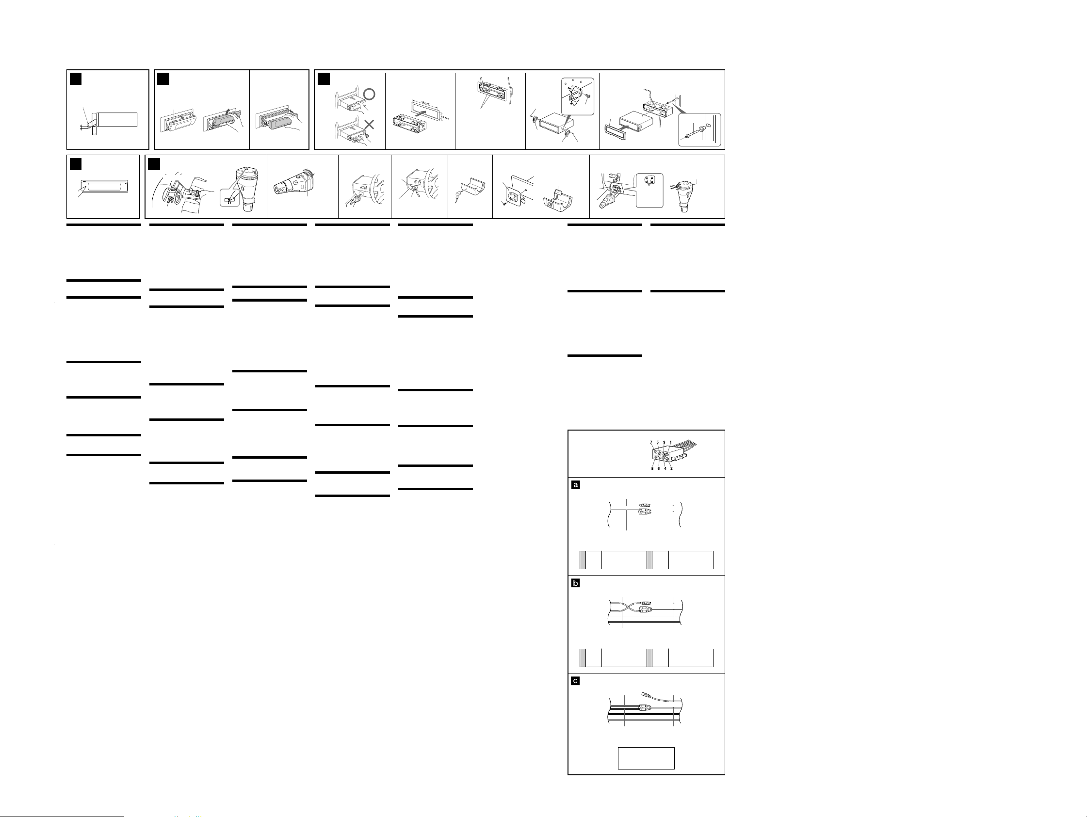
Precautions
•Choose the installation location carefully so that the unit
will not interfere with normal driving operations.
•Avoid installing the unit in areas subject to dust, dirt,
excessive vibration, or high temperature, such as in direct
sunlight or near heater ducts.
•Use only the supplied mounting hardware for a safe and
secure installation.
Mounting angle adjustment
(CDX-M770/M670)
Adjust the mounting angle to less than 60°.
(MDX-M690)
Adjust the mounting angle to less than 20°.
Extended portion of the front
panel (4)
How to detach and attach the
main display window ( 5)
Before installing the unit, detach the front panel.
5-A To detach
1 Press (OPEN) on the unit for 2 seconds.
CD/MD playback or radio reception stops, and the front
panel automatically tilts at an angle of 30°.
2 Detach the main display window as illustrated.
After the main display window detaching is complete,
the front panel closes automaticaly.
5-B To attach
Place the main display window on the front side of the unit
as illustrated, then lightly push the front panel into
position until it clicks.
Mounting example ( 6)
Installation in the dashboard
6-
Note
*
When installing this unit, be sure to close the front
panel of the unit.
If the front panel is opened while installing and given too
much force, it may cause a malfunction.
Warning when installing in a car
without ACC (accessory) position
on the ignition key switch
Be sure to press (OFF) on the unit for two seconds to
turn off the clock display after turning off the engine.
When you press (OFF) only momentarily, the clock
display does not turn off and this causes battery wear.
Reset button (7)
When the installation and connections are completed, be
sure to press the Reset button with a ballpoint pen, etc.
Installing the rotary commander
(RM-X5S) (8)
Notes
• Choose the mounting location carefully so that the rotary
commander will not interfere with operating the car.
• Do not install the rotary commander where it may
jeopardize the safety of the (front) passenger in anyway.
• When installing the rotary commander, be sure not to
damage the electrical cables etc. on the other side of the
mounting surface.
• Avoid installing the rotary commander where it may be
subject to high temperatures, such as from direct sunlight
or hot air from the heater etc.
• The Rev/Nor-select switch is located on the bottom of the
rotary commander. Select “Nor” to use the rotary
commander as the factory-set position. Select “Rev” when
you mount the rotary commander on the right side of the
steering column.
Tip
Rev/Nor cannot be selected on the side of master unit.
1 Press the buttons and rotate the controls to make
sure that your master unit reacts well.
You can change the direction of infrared rays by turning
the dial on the rotary commander.
Caution
Be sure that the place where you install the rotary
commander is within the range of receptor on the unit.
2 Choose the exact location for the rotary
commander to be mounted, then clean the
mounting surface.
Dirt or oil impair the adhesive strength of the doublesided adhesive tape.
3 Mark position for the supplied screw.
Use the screw holes on the mounting hardware 0 to
mark the positions.
If you cannot make the mounting hardware 0 fit easy,
cut the mounting hardware 0 to fit the steering wheel
column cover.
4 Remove the steering wheel column cover, and drill
2 mm diameter hole where you have marked.
5 Warm the mounting surface and the double-sided
adhesive tape on the mounting hardware 0 to the
temperature of 20 °C to 30 °C, and attach the
mounting hardware 0 onto the mounting surface
by applying even pressure. Then screw it down
with the supplied screw 9.
Attach a piece of heavy duty tape etc. on the other side
of the mounting surface to cover the protruding tips of
the screws so that they will not interfere with the
electrical cables etc. inside the steering wheel column.
6 After installing the steering wheel column cover,
attach the rotary commander to the mounting
hardware by aligning the four holes on the bottom
of the rotary commander to the four catches on the
mounting hardware and sliding the rotary
commander until it locks into place as illustrated.
Cautions
• Be sure to attach the supplied strap qa when installing the
rotary commander near the steering wheel.
• Be sure that the strap qa does not get caught on the car
controls (gear, shifter, etc.).
• Be sure to tighten the stopper of the strap qa after
hanging the strap qa on the indicator switch, etc.
Tip
There are two holes for the strap qa. You can use whichever
hole you prefer.
Note
If you are mounting the rotary commander to the steering
wheel column, make sure that the protruding tips of the
screws on the inner surface of the column do not in anyway
hinder or interfere with the movement of the rotating shaft,
operative parts of the switches or the electrical cables etc.
inside the column.
5 6AB 23
(OPEN)
*
c
Mounting example
Montagebeispiel
8 23 41
Exemple de montage
Vorsichtsma§nahmen
•Wählen Sie den Einbauort sorgfältig so aus, daß das
Gerät beim Fahren nicht hinderlich ist.
•Bauen Sie das Gerät so ein, daß es keinen hohen
Temperaturen (keinem direkten Sonnenlicht, keiner
Warmluft von der Heizung), keinem Staub, keinem
Schmutz und keinen starken Vibrationen ausgesetzt ist.
•Für eine sichere Befestigung verwenden Sie stets nur die
mitgelieferten Montageteile.
Hinweis zum Montagewinkel
(CDX-M770/M670)
Das Gerät sollte in einem Winkel von weniger als 60°
montiert werden.
(MDX-M690)
Das Gerät sollte in einem Winkel von weniger als 20°
montiert werden.
berstehender Teil der
Frontplatte ( 4)
Abnehmen und Anbringen des
Haupt-Displays (5)
Nehmen Sie die Frontplatte vor dem Einbau des
Geräts ab.
5-A Abnehmen
1Drücken Sie 2 Sekunden lang (OPEN) am Gerät.
Die CD/MD-Wiedergabe bzw. der Radioempfang
stoppt, und die Frontplatte wird automatisch in einem
Winkel von 30 Grad geneigt.
2 Nehmen Sie das Haupt-Display wie in der
Abbildung dargestellt ab.
Wenn das Haupt-Display abgenommen ist, schließt sich
die Frontplatte automatisch.
5-B Anbringen
Setzen Sie das Haupt-Display wie in der Abbildung
dargestellt an die Vorderseite des Geräts an, und drücken
Sie die Frontplatte dann leicht in die richtige Position, bis
sie mit einem Klicken einrastet.
Montagebeispiel ( 6)
Installation im Armaturenbrett
6-
Hinweis
*
Achten Sie beim Einbau des Geräts darauf, die
Frontplatte geschlossen zu halten.
Wenn sich die Frontplatte beim Einbau öffnet und Sie zu
stark darauf drücken, kann es zu einer Fehlfunktion kommen.
Warnhinweis zur Installation des
Gerts in einem Auto mit Zndschlo§
ohne Zubehrposition ACC oder I
Drücken Sie am Gerät unbedingt zwei Sekunden lang
(OFF), um die Uhrzeitanzeige auszuschalten,
nachdem Sie den Motor ausgeschaltet haben.
Wenn Sie (OFF) nur kurz drücken, wird die
Uhrzeitanzeige nicht ausgeschaltet, und der Autobatterie
wird Strom entzogen.
Rcksetztaste (7)
Nach der Installation und dem Anschluß muß die
rücksetztaste mit einem Kugelschreiber o. ä. gedrückt werden.
Installieren des Joystick
(RM-X5S) (8)
Hinweise
• Wählen Sie den Montageort sorgfältig aus, so daß der
Joystick beim Fahren nicht im Wege ist.
• Montieren Sie den Joystick nicht an einer Stelle, an der er
eine Gefahr für den Beifahrer auf dem Vordersitz
darstellen könnte.
• Achten Sie bei der Montage des Joystick darauf, die
Elektrokabel an der anderen Seite der Montagefläche
nicht zu beschädigen.
• Montieren Sie den Joystick nicht an einer Stelle, an der er
hohen Temperaturen, zum Beispiel direktem Sonnenlicht
oder der Warmluft aus der Wagenheizung, ausgesetzt ist.
• Der Wählschalter Rev/Nor befindet sich an der Unterseite
des Joysticks. Wählen Sie „Nor“, wenn die werkseitig
voreingestellte Drehrichtung der Regler beibehalten
werden soll. Wählen Sie „Rev“, wenn Sie den Joystick auf
der rechten Seite der Lenksäule anbringen.
Tip
Rev/Nor kann nicht mit dem Hauptgerät ausgewählt werden.
1Drücken Sie die Tasten, drehen Sie die Regler, und
vergewissern Sie sich, daß das Hauptgerät
entsprechend reagiert.
Sie können die Richtung der Infrarotstrahlen ändern,
indem Sie den Regler am Joystick drehen.
Vorsicht
Vergewissern Sie sich, daß der Montageort des Joysticks
innerhalb der Reichweite des Empfängers am Gerät ist.
2Wählen Sie die Stelle aus, an der Sie den Joystick
montieren wollen, und reinigen Sie dann die
Montagefläche.
Staub oder Fettspuren beeinträchtigen die Haftung des
doppelseitigen Klebebandes.
3 Markieren Sie die Stelle zum Anbringen der
mitgelieferten Schraube.
Verwenden Sie dazu die Bohrung im Montageteil 0.
Wenn das Montageteil 0 nicht auf die Abdeckung der
Lenkradsäule paßt, schneiden Sie es bitte zurecht.
4 Nehmen Sie die Abdeckung der Lenkradsäule ab,
und bohren Sie an der Stelle, die Sie gerade
markiert haben, ein Loch von 2 mm Durchmesser.
5Erwärmen Sie die Montagestelle und das
doppelseitige Klebeband am Montageteil 0 auf
eine Temperatur von 20 bis 30 °C, und drücken Sie
dann das Montageteil 0 mit gleichmäßigem Druck
auf die Montagestelle. Befestigen Sie es dann mit
der mitgelieferten Schraube 9.
Bringen Sie ein Stück sehr festes Klebeband o. ä. an der
Gegenseite der Montagefläche an, um die vorstehenden
Spitzen der Schrauben abzudecken, damit diese nicht
die Elektrokabel in der Lenkradsäule beschädigen
können.
6 Bringen Sie nun die Abdeckung der Lenkradsäule
wieder an, und befestigen Sie dann den Joystick
auf dem Montageteil, indem Sie die vier
Aussparungen an der Unterseite des Joysticks an
den vier Haken auf dem Montageteil ausrichten
und den Joystick daraufschieben, bis er einrastet,
wie auf der Abbildung zu sehen.
Vorsicht
• Achten Sie darauf, den mitgelieferten Riemen qa
anzubringen, wenn Sie den Joystick in der Nähe des
Lenkrades installieren.
• Achten Sie darauf, daß sich der Riemen qa nicht an
Bedienelementen des Fahrzeugs verfängt (Schalthebel,
Handbremse usw.).
• Achten Sie darauf, den Stopper des Riemens qa
anzuziehen, nachdem Sie den Riemen qa an den
Blinkerhebel o. ä. gehängt haben.
Tip
Für den Riemen qa sind zwei Aussparungen vorhanden. Sie
können sie nach Belieben auswählen.
Hinweis
Wenn Sie den Joystick an der Lenkradsäule montieren,
achten Sie darauf, daß die vorstehenden Spitzen der
Schrauben an der Innenfläche der Lenkradsäule die
Bewegung der Lenkwelle, die Funktionsteile der Schalter
bzw. die Elektrokabel innerhalb der Lenkradsäule in keiner
Weise behindern.
Esempio di montaggio
Montagevoorbeeld
Rev Nor
Infrared rays dial
Regler für Infrarotstrahlen
Molette de réglage des rayons IR
Manopola raggi infrarossi
Knop infraroodstralen
Prcautions
•Choisissez soigneusement l’emplacement de l’installation
afin que l’appareil ne gêne pas la conduite normale du
véhicule.
•Evitez d’installer l’appareil dans un endroit exposé à la
poussière, à la saleté, à des vibrations excessives ou à des
températures élevées comme en plein soleil ou à
proximité de conduits de chauffage.
•Pour garantir un montage sûr, n’utilisez que le matériel
fourni.
Rglage de langle de montage
(CDX-M770/M670)
Ajustez l’inclinaison à un angle inférieur à 60°.
(MDX-M690)
Ajustez l’inclinaison à un angle inférieur à 20°.
Partie tendue de la faade (4)
Comment retirer et fixer lcran
mobile (5)
Avant d’installer l’appareil, retirez la façade.
5-A Pour retirer
1
Appuyez sur la touche (OPEN) de l’appareil pendant
2 secondes.
la lecture du CD/MD ou la radio s’arrête et la façade
s’incline automatiquement suivant un angle de 30 degrés.
2 Retirez l’écran mobile de la façon indiquée dans
l’illustration.
Lorsque vous avez entièrement retiré l’écran mobile, la
façade se referme automatiquement.
5-B Pour poser
Placez l’écran mobile devant l’appareil ainsi qu’il est indiqué
dans l’illustration, puis exercez une légère pression sur la
façade jusqu’à ce qu’il s’encliquette.
Exemple de montage (6)
Installation dans le tableau de bord
6-
Remarque
*
Pendant l’installation de l’appareil, vérifiez que le
panneau avant de cet appareil est fermé.
Si le panneau avant est ouvert pendant l’installation et s’il
subit une force trop importante, un dysfonctionnement
risque de se produire.
Avertissement en cas dinstallation
dans une voiture dont le contact ne
comporte pas de position ACC
(accessoires)
Appuyez sur la touche (OFF) de l’appareil pendant
deux secondes pour désactiver l’affichage de
l’horloge après avoir coupé le moteur.
Si vous n’appuyez que brièvement sur (OFF), l’affichage
de l’horloge ne disparaît pas, ce qui provoque la décharge
de la batterie.
Touche de rinitialisation ( 7)
Quand l’installation et les raccordements sont terminés,
appuyez sur la touche de rèinitialisation avec un stylo à
bille, etc.
Installation du satellite de
commande (RM-X5S) (8)
Remarques
• Choisissez soigneusement l’endroit de montage afin que le
satellite de commande n’interfère pas avec les commandes
de la voiture.
• N’installez pas le satellite de commande dans un endroit
qui risque de compromettre la sécurité du passager avant
de quelque façon que ce soit.
• Lors de l’installation du satellite de commande, veillez à
ne pas endommager les câbles électriques, etc., situés de
l’autre côté de la surface de montage.
• Evitez d’installer le satellite de commande là où il risque
d’être soumis à des températures élevées comme sous le
rayonnement direct du soleil ou à côté d’une conduite de
chauffage, etc.
• Le commutateur de sélection Rev/Nor est situé dans la
partie inférieure du satellite de commande.
Sélectionnez “Nor” pour utiliser le satellite de commande
dans la position définie par défaut.
Sélectionnez “Rev” si vous montez le satellite de
commande du côté droit de la colonne de direction.
Conseil
Il est impossible de sélectionner Rev/Nor sur le côté de
l’appareil principal.
1 Appuyez sur les boutons et tournez les commandes
pour vérifier que l'appareil principal réagit
correctement.
Vous pouvez changer le sens des rayons IR en tournant
la molette située sur le satellite de commande.
Précaution
Assurez-vous que l’endroit où vous installez le satellite de
commande est à portée du récepteur de l’appareil.
2 Choisissez la position de montage exacte du
satellite de commande et nettoyez la surface de
montage.
Les souillures et l’huile altèrent le pouvoir adhérent de
l’adhésif double face.
3 Marquez la position pour la vis fournie.
Utilisez l’orifice de vissage du support de montage 0
pour marquer les positions.
Si vous ne parvenez pas à ajuster aisément le support de
montage 0, découpez-le afin qu'il s'adapte à la colonne
de direction.
4Déposez la garniture de la colonne de direction et
percez un trou de 2 mm de diamètre aux endroits
que vous avez marqués.
5 Chauffez la surface de montage et l’adhésif double
face sur le support de montage 0 à une
température comprise entre 20 °C et 30 °C et fixez
le support de montage sur la surface de montage
0 en exerçant une pression uniforme. Vissez
ensuite la vis 9 fournie.
Collez de la bande adhésive résistante, etc., de l’autre
côté de la surface de montage de manière à couvrir
l’extrémité saillante des vis de telle sorte qu’elle ne
puissent entrer en contact direct avec les câbles
électriques, etc., à l’intérieur de la colonne de direction.
6 Après avoir remonté le couvercle de la colonne de
direction, fixez le satellite de commande sur le
support de montage en alignant les quatre orifices
pratiqués à la base du satellite sur les quatre ergots
du support de montage et faites coulisser le
satellite de commande jusqu’à ce qu’il s’encliquette
dans sa position définitive comme illustré.
Précautions
• Lors de l’installation du satellite de commande près du
volant, veillez à bien fixer la courroie qa fournie.
• Assurez-vous que la courroie qa ne soit pas prise dans les
commandes du véhicule (levier de vitesses, etc.).
• Assurez-vous de bien serrer la vis de sécurité de la courroie
qa après avoir accroché celle-ci au levier de changement
de direction, etc.
Conseil
Il existe deux orifices réservés à la courroie qa. Vous pouvez
utiliser indifféremment l’un ou l’autre.
Remarque
Si vous montez le satellite de commande sur la colonne de
direction, assurez-vous que l’extrémité saillante des vis à
l’intérieur de la colonne de direction n’entrave en aucune
façon le mouvement de l’axe, des organes de commande, des
commutateurs ou des câbles électriques, etc., à l’intérieur de
la colonne de direction.
Precauzioni
•Scegliere con attenzione la posizione per l’installazione in
modo che l’apparecchio non interferisca con le operazioni
di guida del conducente.
•Evitare di installare l’apparecchio dove sia soggetto ad
alte temperature, come alla luce solare diretta o al getto di
aria calda dell’impianto di riscaldamento, o dove possa
essere soggetto a polvere, sporco e vibrazioni eccessive.
•Usare solo il materiale di montaggio in dotazione per
un’installazione stabile e sicura.
Regolazione dellangolo di montaggio
(CDX-M770/M670)
Regolare l’angolo di montaggio in modo che sia inferiore a 60°.
(MDX-M690)
Regolare l’angolo di montaggio in modo che sia inferiore a 20°.
parte sporgente del pannello
anteriore ( 4)
Come rimuovere e applicare la
finestra del display principale ( 5)
Prima di installare l’apparecchio rimuovere il pannello
anteriore.
5-A Per rimuoverlo
1 Premere (OPEN) sull’apparecchio per 2 secondi.
la riproduzione di CD/MD o la ricezione radio si
arresta, quindi il pannello anteriore si inclina
automaticamente di 30 gradi.
2 Rimuovere la finestra del display principale, come
illustrato.
Una volta completata la rimozione della finestra del
display principale, il pannello anteriore si chiude
automaticamente.
5-B Per reinserirlo
Posizionare la finestra del display principale sul lato
anteriore dell’apparecchio come illustrato, quindi spingere
il pannello anteriore evitando di esercitare eccessiva
pressione fino a quando non scatta in posizione.
Esempio di montaggio (6)
Installazione nel cruscotto
6-
Nota
*
Durante l’installazione dell’apparecchio, assicurarsi
di chiudere il relativo pannello anteriore.
Se durante l’installazione il pannello anteriore è aperto e
viene esercitata eccessiva forza, è possibile che si
verifichino problemi di funzionamento.
Informazioni importanti per quando
si effettua linstallazione su unauto
sprovvista della posizione ACC
sullinterruttore di accensione
Assicurarsi di premere (OFF) sull’apparecchio per due
secondi per spegnere il display dell’orologio dopo che
il motore è stato spento.
Se si preme (OFF) solo per un attimo, il display
dell’orologio non si spegne causando in questo modo lo
scaricamento della batteria.
Tasto di azzeramento (7)
Dopo avere terminato l’installazione e i collegamenti,
assicurarsi di premere il tasto di azzeramento con la punta
di una penna a sfera, ecc.
Installazione del telecomando a
rotazione (RM-X5S) (8)
Note
• Scegliere attentamente la posizione di montaggio in modo
che il telecomando a rotazione non interferisca con la guida.
• Non installare il telecomando a rotazione in posizione tale
da poter compromettere in alcun modo la sicurezza del
passeggero.
• Al momento di installare il telecomando a rotazione
assicurarsi di non danneggiare i cavi elettrici ecc. nella parte
posteriore della superficie di montaggio.
• Non installare il telecomando a rotazione in posizione
soggetta ad alte temperature, ad esempio esposto alla luce
solare diretta o al calore proveniente dall’impianto di
riscaldamento della vettura.
• L’interruttore di selezione Rev/Nor è situato nella parte
inferiore del telecomando a rotazione.
Selezionare “Nor” per utilizzare il telecomando a rotazione
con le impostazioni di fabbrica. Selezionare “Rev” quando il
telecomando a rotazione viene montato sul lato destro del
piantone di guida.
Suggerimento
Non è possibile selezionare Rev/Nor dall’unità principale.
1
Premere i tasti e ruotare i comandi per verificare che
l'apparecchio principale funzioni correttamente.
È possibile cambiare la direzione dei raggi infrarossi
ruotando la manopola sul telecomando a rotazione.
Attenzion
Assicurarsi che il luogo in cui viene installato il telecomando
a rotazione sia all’interno della gamma del ricettore
dell’unità principale.
2 Scegliere la posizione esatta di montaggio del
telecomando a rotazione, quindi pulire la superficie
di montaggio.
La sporcizia o l’unto possono pregiudicare la tenuta del
nastro biadesivo.
3 Segnare la posizione di montaggio per la vite in
dotazione.
Usare il foro per la vite sulla staffa di montaggio 0 per
segnare la posizione.
Se non è possibile installare la staffa di montaggio 0
facilmente; tagliare la staffa di montaggio 0 per
adattarla alla copertura del piantone di guida.
4 Rimuovere il coperchio della colonna del volante e
praticare un foro di 2 mm di diametro nella
posizione contrassegnata.
5 Riscaldare la superficie di montaggio e il nastro
biadesivo sulla staffa di montaggio 0 ad una
temperatura compresa tra 20 °C e 30 °C. Applicare
la staffa di montaggio 0 sulla superficie di
montaggio esercitando una pressione omogenea,
quindi fissarla avvitando la vite 9 in dotazione.
Applicare una striscia di nastro adesivo pesante sull’altro
lato della superficie di montaggio in modo da coprire la
punta sporgente delle viti perché queste non interferiscano
con i cavi elettrici all’interno della colonna del volante.
6 Dopo aver rimontato il coperchio della colonna del
volante, montare il telecomando allineando i
quattro fori sul fondo del comando ai quattro fermi
sulla staffa di montaggio e facendo scorrere il
telecomando fino a che non si blocca in posizione,
come illustrato in figura.
Attenzione
• Assicurarsi di inserire il cordino qa in dotazione quando si
installa il telecomando a rotazione vicino al volante.
• Assicurarsi che il cordino qa non rimanga incastrato tra i
comandi dell’automobile (cambio, pedali, ecc.).
• Assicurarsi di stringere il fermo del cordino qa dopo aver
applicato il cordino qa all’interruttore dell’indicatore e così
via.
Suggerimento
Esistono due fori per il cordino qa.
Utilizzare indifferentemente uno dei due.
Nota
Se il telecomando viene montato sulla colonna del volante,
assicurarsi che le punte sporgenti delle viti sulla superficie
interna della colonna non pregiudichino o interferiscano in
alcun modo con il movimento dell’albero, con i componenti
degli interruttori o con i cavi elettrici etc. all’interno della
colonna.
1
1
0
Mark
Markierung
Marques
Contrassegno di montaggio
Merkteken
Voorzorgsmaatregelen
•Kies de installatieplaats zorgvuldig zodat het toestel de
bestuurder niet hindert tijdens het rijden.
•Installeer het apparaat niet op plaatsen waar het
blootgesteld wordt aan hoge temperaturen, b.v. in direct
zonlicht of bij de warme luchtstroom van de
autoverwarming, aan sterke trillingen, of waar het in
contact komt met veel stof of vuil.
•Gebruik voor het veilig en stevig monteren van het
apparaat uitsluitend de bijgeleverde montageonderdelen.
Maximale montagehoek
(CDX-M770/M670)
Installeer het apparaat nooit onder een hoek van meer
dan 60° met het horizontale vlak.
(MDX-M690)
Installeer het apparaat nooit onder een hoek van meer
dan 20° met het horizontale vlak.
Verlengstuk van het frontpaneel
(4)
Het hoofddisplay losmaken en
bevestigen (5)
Verwijder, alvorens met het installeren te beginnen,
het afneembare voorpaneel.
5-A Verwijderen
1 Hou (OPEN) op het toestel 2 seconden ingedrukt.
CD/MD-weergave of radio-ontvangst stopt en het
frontpaneel kantelt automatisch in een hoek van 30
graden.
2 Maak het hoofddisplay los zoals de afbeelding laat
zien.
Nadat het hoofddisplay volledig is losgemaakt, sluit het
frontpaneel automatisch.
5-B Bevestigen
Plaats het hoofddisplay vooraan op het toestel zoals de
afbeelding laat zien en druk het vervolgens lichtjes op zijn
plaats tot het vastklikt.
Montagevoorbeeld ( 6)
Montage in het dashboard
6-
Opmerking
*
Bij het installeren van het toestel dient het
frontpaneel te zijn gesloten.
Als het frontpaneel tijdens het installeren open is, kan het
worden geforceerd wat tot een defect kan leiden.
Opgelet bij het monteren in een auto
waarvan het contactslot geen ACC
(accessory) stand heeft
Druk (OFF) op het toestel gedurende twee seconden
in om de klokweergave uit te schakelen na het
afzetten van de motor.
Indien u slechts even op (OFF) drukt, verdwijnt de
tijdindicatie niet waardoor de batterij uitgeput raakt.
Terustelknop (7)
Druk, nadat u het apparaat heeft geïnstalleerd en de
aansluitingen heeft gemaakt, met een balpen of een ander
puntig voorwerp op de terustelknop.
Installatie van de
bedieningssatelliet (RM-X5S) (8)
Opmerkingen
• Ga zorgvuldig te werk bij het kiezen van een geschikte
montagepositie zodat de bedieningssatelliet u nooit
hindert bij het rijden.
• Installeer de bedieningssatelliet nooit op een plaats waar
hij de veiligheid van de (voor)passagier in gevaar kan
brengen.
• Bij het installeren van de bedieningssatelliet moet u erop
letten dat u de elektrische bedrading en dergelijke aan de
andere kant van het montagevlak niet beschadigt.
• Installeer de bedieningssatelliet niet op plaatsen waar hij
blootstaat aan hoge temperaturen, bijvoorbeeld door
rechtstreekse zonnestraling of warme lucht afkomstig van
de verwarming, enz.
• De Rev/Nor-keuzeschakelaar bevindt zich onderaan op de
bedieningssatelliet.
Kies “Nor” om de bedieningssatelliet te gebruiken met de
fabrieksinstelling.
Kies “Rev” wanneer u de bedieningssatelliet rechts op de
stuurkolom monteert.
Tip
Rev/Nor kan niet worden geselecteerd op het
hoofdtoestel.
1 Druk op de toetsen en draai aan de regelaars om
zeker te zijn dat uw master unit goed functioneert.
U kunt de richting van de infraroodstralen wijzigen
door aan de knop op de bedieningssatelliet te draaien.
Let op!
Zorg ervoor dat u de bedieningssatelliet installeert
binnen het ontvangstbereik van het toestel.
2 Kies de exacte installatieplaats voor de
bedieningssatelliet en maak vervolgens het
montagevlak schoon.
Vuil of vet tasten het kleefvermogen van het
dubbelzijdige plakband aan.
3 Markeer een bevestigingspunt voor de
meegeleverde schroef.
Markeer de posities aan de hand van de schroefgaten
in het bevestigingselement 0.
Als het bevestigingselement 0 niet goed past, moet u
het overtollige gedeelte afsnijden zodat het wel in de
stuurkolombekleding past.
4 Verwijder de stuurkolombekleding en boor een gat
van 2 mm op de gemarkeerde posities.
5 Warm het bevestigingsvlak en de dubbelzijdige
kleefband op het bevestigingselement 0 op tot
een temperatuur van 20 à 30 °C en plaats de steun
op het bevestigingsvlak door gelijkmatig aan te
drukken. Schroef hem vervolgens vast met de
meegeleverde schroef 9.
Breng een stuk tape of iets dergelijks aan op de andere
kant van het bevestigingsvlak om te voorkomen dat de
uitstekende schroefpunten in contact komen met de
elektrische bedrading en dergelijke binnenin de
stuurkolom.
6 Plaats de stuurkolombekleding terug en bevestig
de bedieningssatelliet op het montage-accessoire
door de vier gaten onderaan de bedieningssatelliet
te laten samenvallen met de vier
bevestigingsklemmen op het montage-accessoire
en verschuif de bedieningssatelliet tot hij op zijn
plaats klikt zoals de illustratie laat zien.
Let op!
• Bevestig de meegeleverde riem qa wanneer u de
bedieningssatelliet in de buurt van het stuurwiel
monteert.
• Zorg ervoor dat riem qa niet kan verstrikt raken in de
bedieningselementen van de auto (schakelpook enz).
• Zet de stopper op de riem qa vast nadat u deze hebt
bevestigd aan de richtingaanwijzerhendel enz
Tip
Er zijn twee gaten voor riem qa. U kunt kiezen welk ervan
u gebruikt.
Opmerking
Bij het monteren van de bedieningssatelliet op de
stuurkolom, moet u ervoor zorgen dat de uitstekende
punten van de schroeven aan de binnenkant van de
stuurkolom de stuurstang, schakelaars, elektrische
bedrading, enzovoort in de stuurkolom niet hinderen.
Bend these claws outward for a tight fit, if
necessary.
Falls erforderlich, diese Klammern für einen
sicheren Halt hochbiegen.
Pliez ces griffes pour assurer une prise
correcte si nécessaire.
Piegare questi morsetti per un‘installazione
più sicura, se necessario.
Indien nodig kunt u deze lipjes ombuigen
voor een steviger bevestiging.
5
0
9
5
7
7
Heavy duty tape etc.
Sehr festes Klebeband o. ä.
Bande adhésive résistante, etc.
Nastro adesivo pesante.
Sterke kleefband of dergelijke
7
5
Power connection diagram
Auxiliary power connector may vary depending on the
car. Check your car’s auxiliary power connector diagram
to make sure the connections match correctly. There are
three basic types (illustrated below). You may need to
switch the positions of the red and yellow leads in the car
stereo’s power connecting cord.
After matching the connections and switched power
supply leads correctly, connect the unit to the car’s power
supply. If you have any questions and problems
connecting your unit that are not covered in this manual,
please consult the car dealer.
Stromanschlu§diagramm
Der Hilfsstromanschluß kann je nach Fahrzeugtyp
unterschiedlich sein. Sehen Sie im
Hilfsstromanschlußdiagramm für Ihr Fahrzeug nach, wie
die Verbindung ordnungsgemäß vorgenommen werden
muß. Es gibt, wie unten abgebildet, drei grundlegende
Typen. Sie müssen möglicherweise die rote und gelbe
Leitung des Stromversorgungskabels der
Autostereoanlage vertauschen.
Stellen Sie die Anschlüsse her, schließen Sie die
geschalteten Stromversorgungsleitungen richtig an, und
verbinden Sie dann das Gerät mit der Stromversorgung
Ihres Fahrzeugs. Wenn beim Anschließen des Geräts
Fragen oder Probleme auftreten, die in dieser
Bedienungsanleitung nicht erläutert werden, wenden Sie
sich bitte an den Autohändler.
Schma de connexion
dalimentation
Le connecteur d’alimentation auxiliaire peut varier
suivant le type de voiture. Vérifiez le schéma du
connecteur d’alimentation auxiliaire de votre voiture
pour vous assurer que les connexions correspondent. Il
en existe trois types de base (illustrés ci-dessous). Il se
peut que vous deviez commuter la position du fil rouge
et jaune du cordon d’alimentation de l’autoradio.
Après avoir établi les connexions et commuté
correctement les fils d’alimentation, raccordez l’appareil à
l’alimentation de la voiture. Si vous avez des questions
ou des difficultés à propos de cet appareil qui ne sont pas
abordées dans le présent mode d’emploi, consultez votre
revendeur automobile.
4
5
4
6
qa
Auxiliary power connector
Hilfsstromanschluß
Connecteur d’alimentation auxiliaire
Connettore di alimentazione ausiliare
Hulpvoedingsaansluiting
Yellow
continuous power supply
Gelb
permanente Stromversorgung
4
Jaune
alimentation continue
Giallo
alimentazione continua
Geel
Yellow
switched power supply
Gelb
geschaltete Stromversorgung
4
Jaune
alimentation commutée
Giallo
alimentazione commutata
Geel
geschakelde voeding
Dashboard
Armaturenbrett
Tableau de bord
Cruscotto
Dashboard
1
Holes
Aussparungen
Orifices
Fori
Gaten
Red
Rot
Rouge
Rosso
Rood
Yellow
Gelb
Jaune
Giallo
Geel
continu voeding
Red
Rot
Rouge
Rosso
Rood
Yellow
Gelb
Jaune
Giallo
Geel
7
7
Red
Rot
Rouge
Rosso
Rood
Yellow
Gelb
Jaune
Giallo
Geel
the car without ACC position
Fahrzeug ohne Zubehörposition (ACC)
Voiture sans position ACC
la macchina senza posizione ACC
Wagen zonder ACC stand
Fire wall
Motorraumtrennwand
Paroi ignifuge
Parete tagliafiamma
Brandschot
2
3
the other hole
die andere Aussparung
l’autre orifice
altro foro
ander gat
qa
Diagramma dei collegamenti di
alimentazione
Il connettore di alimentazione ausiliaria può variare a
seconda della macchina. Controllare il diagramma del
connettore di alimentazione ausiliaria della macchina per
essere sicuri che le connessioni corrispondano
correttamente. Vi sono tre tipi di base (illustrazione
sotto). Potrà essere necessario cambiare le posizioni dei
conduttori rosso e giallo nel cavo di alimentazione dello
stereo della macchina.
Dopo aver fatto corrispondere le connessioni e i cavi di
alimentazione commutata, collegare l’apparecchio
all’alimentazione della macchina. Se si hanno domande o
se sorgono problemi che non sono stati trattati nel
manuale nel collegare l’apparecchio, contattare
l’autoconcessionario.
Voedingsaansluitschema
De hulpvoedingsaansluiting kan verschillen naargelang
van de wagen. Controleer het voedingsaansluitschema
dat bij dit toestel wordt geleverd om te zien of de
aansluitingen kloppen. Er zijn drie basistypes (zie
illustratie hieronder).
Als de aansluitingen en geschakelde voedingskabels
kloppen, sluit u het toestel aan op de voeding van de
wagen. Indien u nog vragen of problemen hebt in
verband met het aansluiten van het toestel die niet in
deze handleiding vermeld staan, raadpleeg dan de
autodealer.
Red
Rot
Rouge
Rosso
Rood
Yellow
Gelb
Jaune
Giallo
Geel
Red
switched power supply
Rot
geschaltete Stromversorgung
Rouge
alimentation commutée
Rosso
alimentazione commutata
Rood
geschakelde voeding
Red
Rot
Rouge
Rosso
Rood
Yellow
Gelb
Jaune
Giallo
Geel
Red
continuous power supply
Rot
permanente Stromversorgung
Rouge
alimentation continue
Rosso
alimentazione continua
Rood
continu voeding
Red
Rot
Rouge
Rosso
Rood
Yellow
Gelb
Jaune
Giallo
Geel
77
Page 8
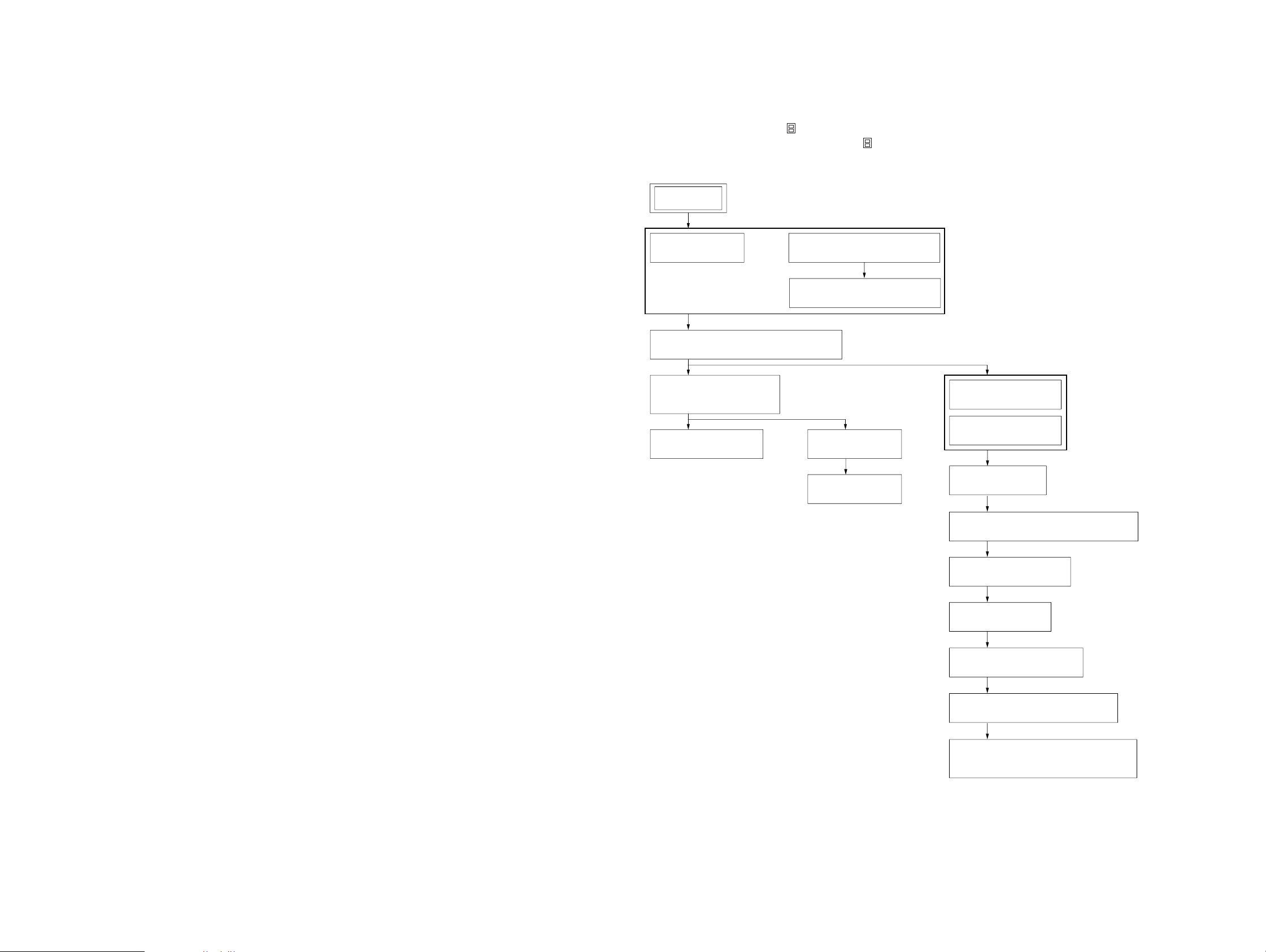
MDX-M690
SECTION 3
DISASSEMBLY
• This set can be disassembled in the order shown below.
3-1. DISASSEMBLY FLOW
Note 1: The process described in can be performed in any order.
Note 2: Without completing the process described in , the next process can not be performed.
Note 3: Illustration of disassembly is omitted.
SET
3-2. COVER
(Page 9)
3-4. MECHANISM DECK (MG-164MA-138)
(Page 10)
3-5. MOTOR BLOCK ASSY,
CAM (R) ASSY
(Page 10)
3-6. SUB PANEL ASSY
(Page 11)
FRONT PANEL (DSPL) ASSY
3-3. FRONT PANEL (KEY) ASSY
(Page 9)
3-7. MAIN BOARD
3-8. HEAT SINK
(Note 3)
(Page 11)
(Page 12)
3-9. SERVO BOARD
(Page 12)
3-10. MD COVER ASSY
(Page 13)
3-11. FLOAT BLOCK
(Page 13)
3-12. LO MOTOR ASSY (LOADING) (M903)
(Page 14)
3-13. LEVER (LE23) ASSY
(Page 14)
3-14. HOLDER ASSY
(Page 15)
3-15. CHUCKING ARM ASSY
(Page 15)
3-16. OPTICAL PICK-UP (KMS-241C)
(Page 16)
3-17. SL MOTOR ASSY (SLED) (M902),
SP MOTOR ASSY (SPINDLE) (M901)
(Page 16)
88
Page 9
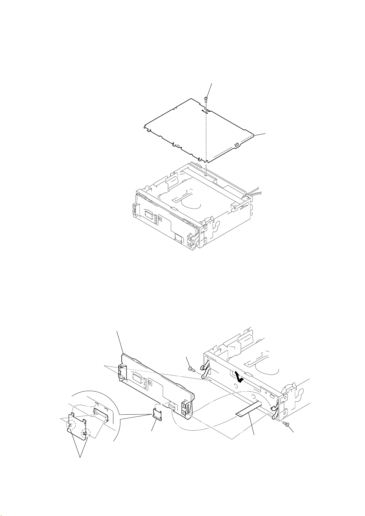
Note: Follow the disassembly procedure in the numerical order given.
r
)
3-2. COVER
1
screw
(PTT2.6 × 6)
2
MDX-M690
cove
3-3. FRONT PANEL (KEY) ASSY
5
Remove the front panel (KEY) assy
in the direction of the arrow.
2
1
two claws
4
guide (flexible)
screw (panel)
3
flexible board
(CN1)
4
screw (panel
9
Page 10
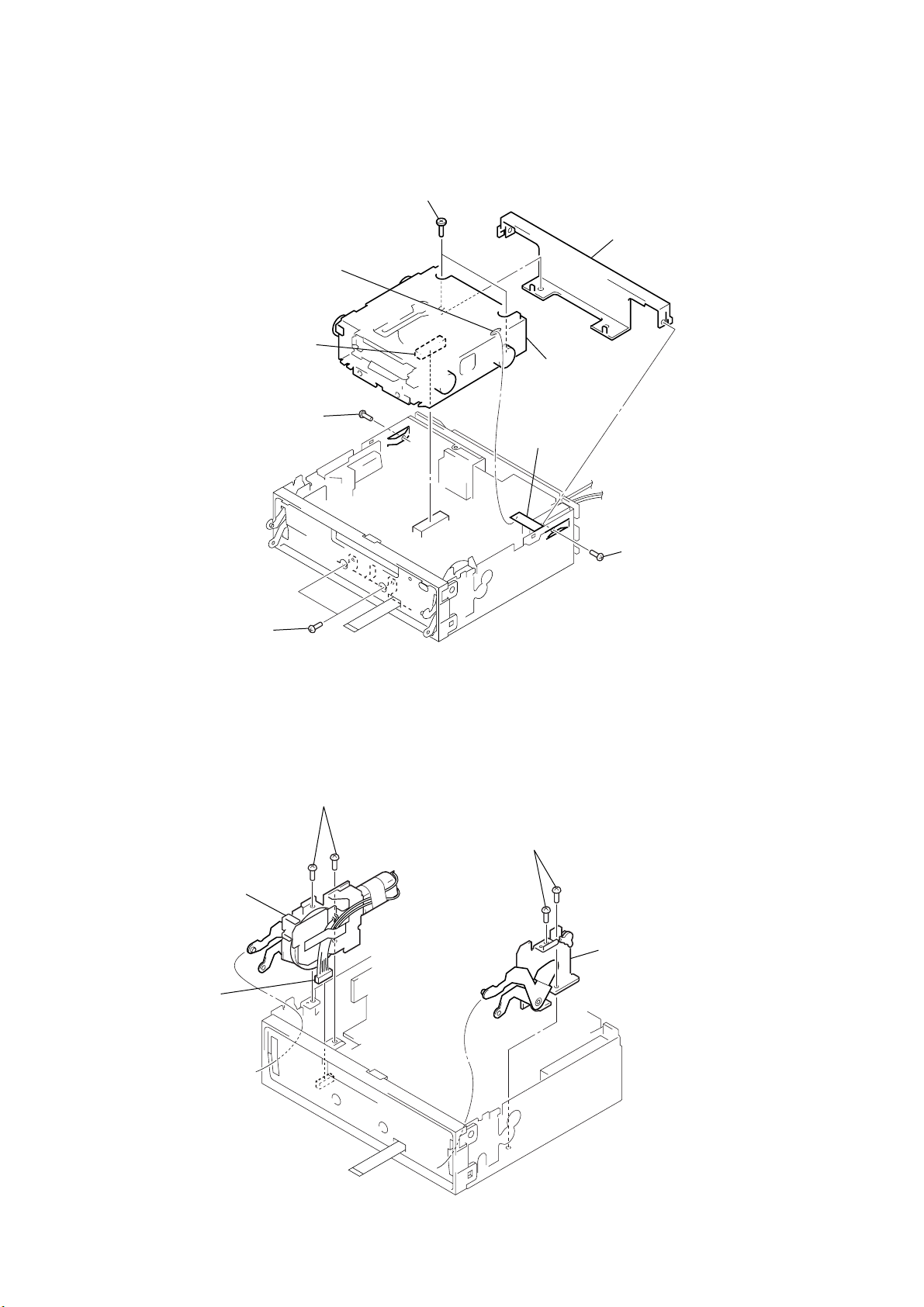
MDX-M690
t
y
3-4. MECHANISM DECK (MG-164MA-138)
1
Remove the solder of
sheet (beat).
3
connector
(CN401)
2
screw
(PTT2.6 × 4)
×
Note: Make sure to install screw (PTT2.6
Installing other screw (PTT2.6 × 4) except
2.6 × 4 damage the set.
4).
4
two screws
(PTT2.6 × 6)
6
mechanism deck (MG-164MA-138)
sheet (beat)
5
bracket (MD)
2
two screws
(PTT2.6 × 6)
3-5. MOTOR BLOCK ASSY, CAM (R) ASSY
2
two screws
3
motor block assy
1
connector
(CN602)
(PTT2.6
×
6)
4
two screws
(PTT2.6
2
screw
(PTT2.6 × 4)
Note: Make sure to install screw (PTT2.6 × 4).
Installing other screw (PTT2.6 × 4) excep
2.6 × 4 damage the set.
×
6)
5
cam (R) ass
10
Page 11
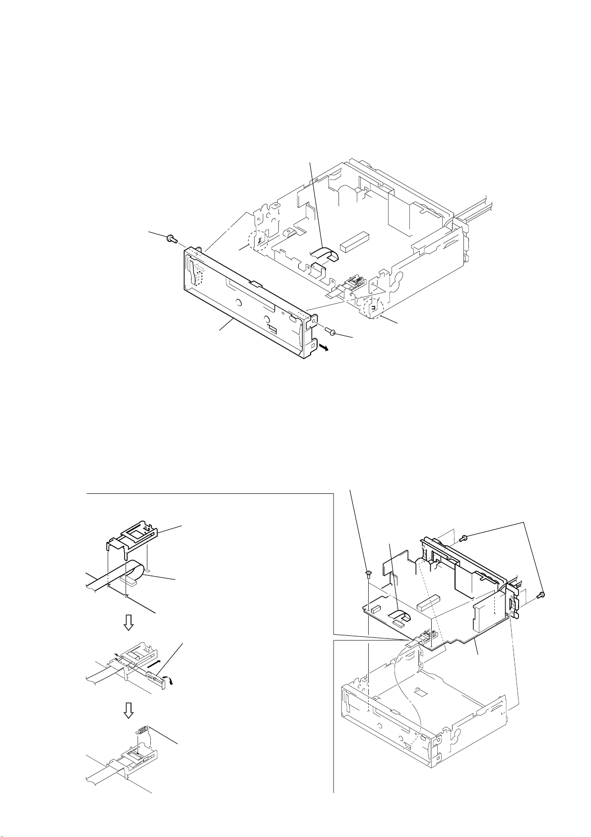
3-6. SUB PANEL ASSY
2
screw
(PTT2.6
×
6)
3
claw
1
flat cable
(CN603)
MDX-M690
4
sub panel assy
3-7. MAIN BOARD
•
Cover (flexible), Slider (flexible) and Tension spring (flexible)
mounting method.
2
cover (flexible)
1
Set the flexible board to be at the
position in the figure.
3
2
screw
(PTT2.6
2
three ground point screws
(PTT2.6
×
1
flat cable
(CN603)
6)
×
6)
claw
3
four screws
(PTT2.6
×
6)
A
C
3
Hold the flexible board with the
slider (flexible) by installing in the
direction of arrow
turn the slider in the direction
of arrow
B
then slide it in the direction
of arrow
4
tension spring (flexible)
B
C
A
,
,
.
4
main board
11
Page 12
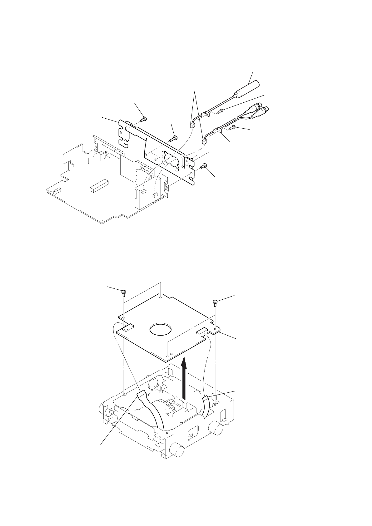
MDX-M690
e
)
3-8. HEAT SINK
8
heat sink
7
screw
(PTT2.6 × 6)
6
two screws
(PTT2.6 × 10)
1
two connectors
(CN201, 301)
7
3
cord (with connector) (ANT)
2
4
screw
(PTT2.6 × 6)
5
cord (with connector) (sub out
screw
(PTT2.6
×
6)
screw
(PTT2.6 × 6)
3-9. SERVO BOARD
2
two screws
(BVTT2
×
4)
2
two screws
(BVTT2
×
4)
3
servo board
1
flexible flat (11core) cabl
(CN103)
12
1
optical pick-up flexible board
(CN102)
Page 13
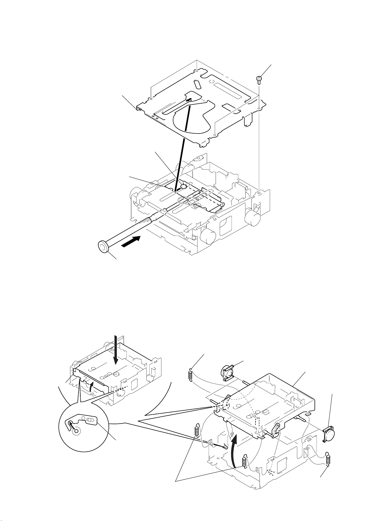
3-10. MD COVER ASSY
)
1
tension spring (float B)
6
float block
1
tension spring (float B)
2
two tension springs (float F)
3
Pushing an arrow A part, raise the float block
up ward at the front to release a lock.
A
4
float block
lever (lock R)
lever (lock L)
5
two dampers assy
5
two dampers assy
3
MD cover assy
shaft (MD cover guide)
cassette holder
1
four screws
(BVTT2 × 4
MDX-M690
3-11. FLOAT BLOCK
A
2
Pushing the cassette holder in the direction of the arrow A with a
screwdriver, etc., disengage the shaft (MD cover guide) from
the slot in the MD cover assy.
Note: Take care not to scratch the optical pick-up when pushing
the cassette holder with a screwdriver. etc.
13
Page 14
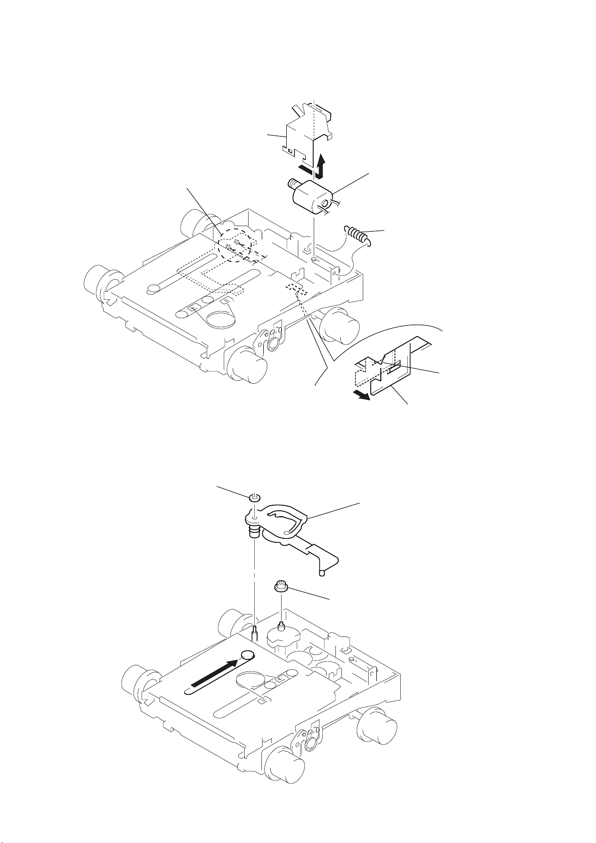
MDX-M690
y
3-12. LO MOTOR ASSY (LOADING) (M903)
4
Remove the bracket (LO)
in the direction of the arrow
A
.
1
Remove solders of motor (M903).
3-13. LEVER (LE23) ASSY
A
5
LO motor assy (loading) (M903)
2
tension spring (rack)
bracket (LO)
– bottom view –
3
claw
2
stopper washer
1
3
lever (LE23) ass
4
roller (gear E)
14
Page 15
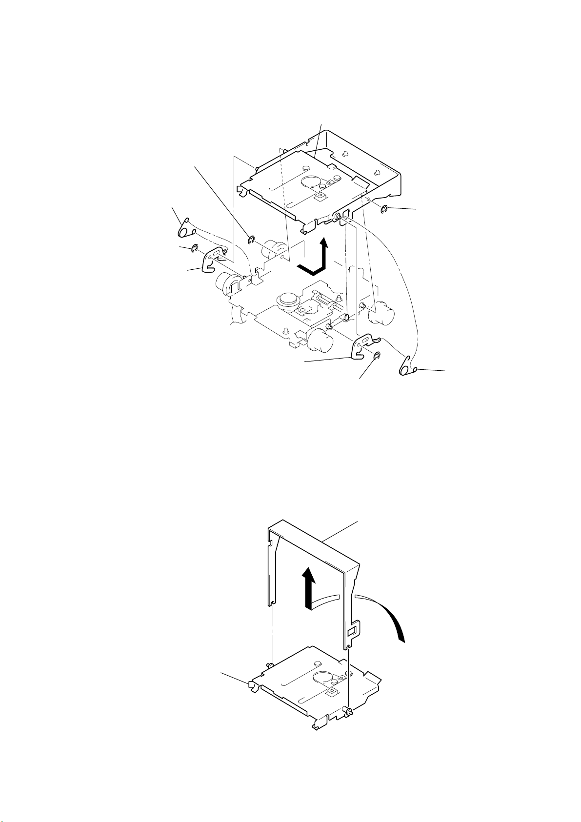
3-14. HOLDER ASSY
)
y
2
type-E stop ring 1.5
1
spring (chucking)
2
type-E stop ring 1.5
3
lever (lock R)
4
Remove the holder assy in the
direction of the arrow.
2
type-E stop ring 1.5
MDX-M690
3-15. CHUCKING ARM ASSY
3
lever (lock L)
2
type-E stop ring 1.5
1
Remove the chucking arm ass
in the direction of the arrow.
1
spring (chucking
holder assy
15
Page 16
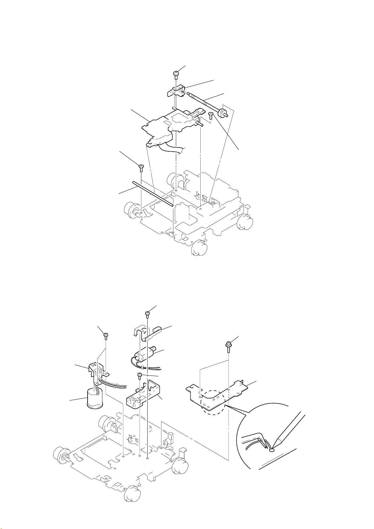
MDX-M690
3-16. OPTICAL PICK-UP (KMS-241C)
7
optical pick-up (KMS-241C)
1
two screws
×
3)
(K2
2
guide shaft (OPT L)
4
screw
(B2
×
3)
6
bearing (SL)
5
feed screw assy
3
screw
×
3)
(K2
3-17. SL MOTOR ASSY (SLED) (M902), SP MOTOR ASSY (SPINDLE) (M901)
4
screw
(P1.7
×
1.8)
9
two screws
(P1.7
×
0
bracket (SP)
qa
SP motor assy
(spindle) (M901)
1.8)
8
5
6
SL motor assy
(sled) (M902)
7
screw
×
(B2
base (SL)
bracket (SL)
3)
2
two screws
(2
×
8)
3
sensor board
16
1
Remove solders of motors
(M901, M902).
Page 17

• This set can be assembled in the order shown below.
4-1. ASSEMBLY FLOW
4-2. MOTOR BLOCK ASSY
(Page 18)
4-3. CAM (R) ASSY
(Page 18)
4-4. ADJUSTING PHASE OF MOTOR BLOCK ASSY, CAM (R) ASSY
(Page 19)
4-5. PHASE CHECK
(Page 19)
MDX-M690
SECTION 4
ASSEMBLY
17
Page 18
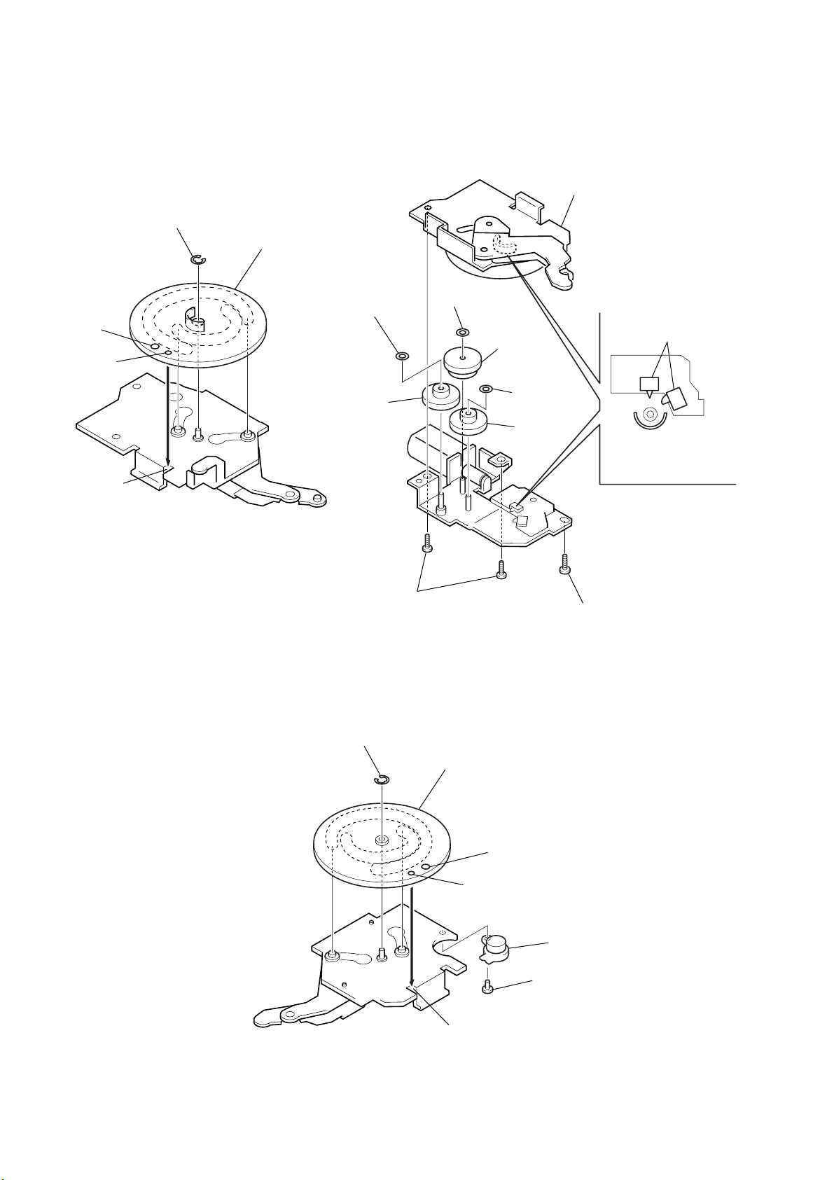
MDX-M690
r
Note: Follow the assembly procedure in the numerical order given.
4-2. MOTOR BLOCK ASSY
2
stop ring 1.5
1
cam (L)
6
hole (large)
hole (small)
4
concave portion
washer (M)
gear (C)
6
washer (M)
5
gear (A)
6
washer (M)
3
gear (B)
7
bracket (L) assy
Set bracket (L) assy
to be at the position in the
figure.
switch
Note: When installing cam (L), adjust the hole (small) and concave portion.
8
two screws
(PTT2.6
4-3. CAM (R) ASSY
2
stop ring 1.5
8
×
6)
1
cam (R)
hole (large)
hole (small)
screw
(PTT2.6
×
6)
18
3
oil dampe
4
screw
(P2
×
4)
concave portion
Note: When installing cam (R), adjust the hole (small) and concave portion.
Page 19
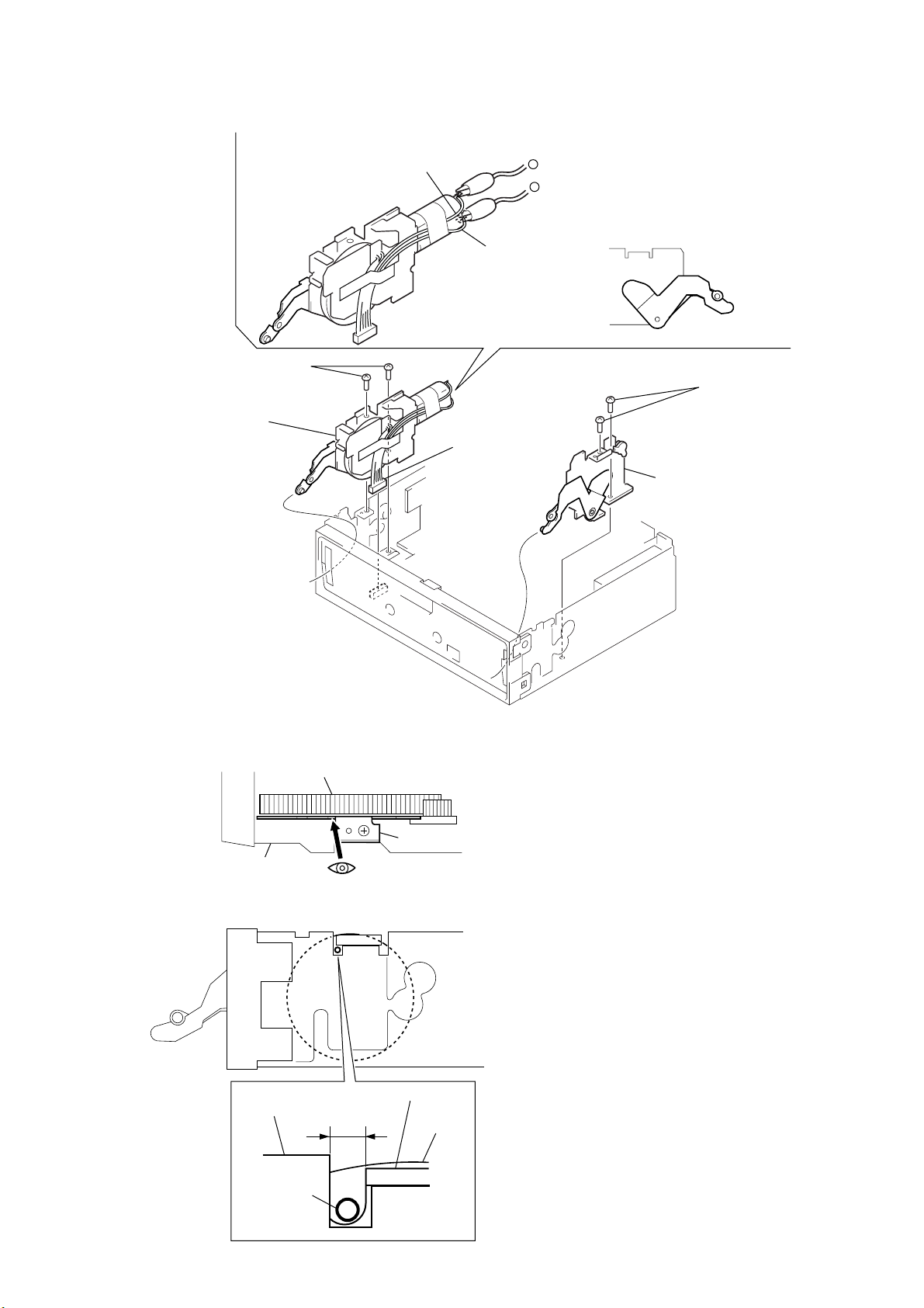
4-4. ADJUSTING PHASE OF MOTOR BLOCK ASSY, CAM (R) ASSY
e
1
Supply the power to the motor.
Voltage : 9V
Yellow wiring : MOTOR –
Black wiring : MOTOR +
2
Motor stops at full open position.
3
motor block assy
Note :
Install the cam
in a full open position.
4
two screws
(PTT2.6
yellow wiring
×
6)
5
connector
(CN602)
–
+
black wiring
full open position
7
two screws
(PTT2.6
6
cam (R) assy
Note :
Install the cam
in a full open position.
MDX-M690
×
6)
4-5. PHASE CHECK
– Up view –
chassis (MD) assy
– Right side view –
chassis (MD) assy
cam (R)
#
look position
#
A
bracket (R) assy
bracket (R) assy
cam (R)
1. Look into the position pointed by
figure from the direction of the arrow.
2. Check that the hole (small) of the cam (R) is
within the range of A.
3. Check 2 with both L and R side.
If it is OK in both sides, the cam is in phase.
(If not, adjust it.)
!
in th
hole (small)
19
Page 20

MDX-M690
SECTION 5
ELECTRICAL ADJUSTMENTS
TEST MODE
This set have the test mode function.
<Set the Test Mode>
1. Turn ON the regulated po wer supply. (The clock is displayed)
Note: Press the [OFF] button, if the clock is not displayed.
2. Push the preset [4] button.
3. Push the preset [5] button.
4. Press the preset [1] button for more than two seconds.
5. Then the display indicates all lights, the test mode is set.
<Release the Test mode>
1. Push the [OFF] button.
Note:
In the normal mode, after pressing the [OPEN] key for two seconds to set
the front panel in detaching position and detaching the display panel is
complete, the front panel closes automatically.
But in the test mode, the front panel opens automatically.
MD SECTION
MD section adjustments are done automatically in this set.
TUNER SECTION
Tuner section adjustments are done automatically in this set.
20
Page 21
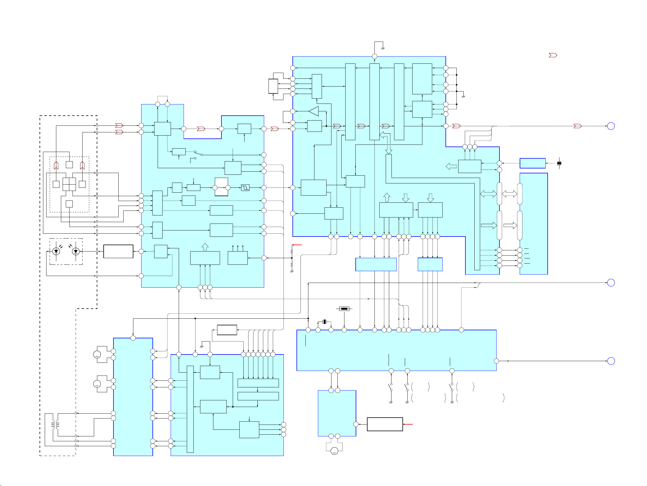
SECTION 6
DIAGRAMS
MDX-M690
6-1. BLOCK DIAGRAM – SERVO Section –
OPTICAL PICK-UP BLOCK
(KMS-241C)
F
C B
I J
A
D
E
DETECTOR
LDPD
LASER DIODE
ILCC
RM
I
J
B
A
C
D
E
F
AUTOMATIC
POWER CONTROL
Q302
48 47
MORFO
I
1
RF AMP
J
2
A
4
B
5
I-V
C
AMP
6
D
7
E
8
I-V
F
AMP
9
APC
LD/PD
11
10
AMP
PD
MORFI
RFO
46 40
B.P.F.
3T
AT
AMP
ABCD
AMP
APCREF
12
TEMP
WBL
ADFM ADIN
B.P.F.
COMMAND
SERIAL/PARALLEL
CONVERTER,
DECODER
SWDT
FOCUS/TRACKING ERROR AMP
AGCI
BOTTOM
3029
FOCUS
ERROR AMP
TRACKING
ERROR AMP
SCLK
XLAT
181716
DIGITAL SIGNAL PROCESSOR,
EFM/ACIRC ENCODER/DECODER,
SHOCK PROOF MEMORY CONTROLLER,
ATRAC ENCODER/DECODER
IC301 (1/2)
FILTER
RF AMP,
IC302
RF
WBL
PEAK &
EQ
V-I
CONVERTER
RF AGC
& EQ
EQ
3T
WBL
AUX
PEAK
BOTM
ADFG
ABCD
F0CNT
38
33
37
36
32
35
FE
34
TE
26
SE
28
20
100
EFMO
FILI
60
PCO
59
CLTV
62
FILO
61
ASYO
53
ASYI
54
RFI
57
78
F0CNT
79
COMPA-
RATOR
ADIP
ADFG
DEMODULATOR/
DECODER
+3.3V
PLL
SPINDLE
SERVO
SPFD
94 93
PROCESSOR
SPRD
15
EFM/ACIRC
ENCODER/DECODER
SUBCODE
DQSY11SQSY14XINT
12
SHOCK PROOF
LEVEL SHIFT
IC502 (1/2)
TX
ATRAC
CPU
INTERFACE
SRDT
SWDT
17
3
ENCODER/DECODER
MEMORY CONTROLLER
SENS
9 8 5 6 7
111315
975
SCLK
XLAT
SAMPLING
RATE
CONVERTER
DIGITAL
AUDIO
INTERFACE
INTERNAL BUS
MONITOR
CONTROL
MNT0
MNT1
1 2 3 4
246
LEVEL SHIFT
IC502 (2/2)
181614
ADDT
DATAI
XBCKI
LRCKI
DIN0
DIN1
DOUT
DADT
MNT2
MNT3
8
12
• SIGNAL PATH
: MD PLAY
25
22
24
23
19
20
21
LRCK
CLOCK
2927
FS256
DATA
BCK
LRCK
256FS
XRAS
XCAS
OSCI
OSCO
D0 – D3A00 – A09
XOE
XWE
16
17
49, 48, 50, 5134 – 31, 36 – 40, 45
43
47
46
44
1024FS OSC
IC304
D0 – D3
1, 2, 24, 25
D-RAM
IC307
A00 – A09
9 – 12, 14 – 18, 5
22
OE
3
WE
RAS
4
CAS
23
X301
45MHz
26
28
XBCK
GENERATOR
MD-RST
DEEMP
DATA, BCK,
LRCK, 256FS
MD-RST,
DEEMP
A
B
(Page 23)
(Page 23)
2-AXIS
DEVICE
(TRACKING)
FCS+
(FOCUS)
FCS–
TRK+
TRK–
FOCUS/TRACKING COIL DRIVE,
SPINDLE/SLED MOTOR DRIVE
IC303
M901
M902
(SLED)
MM
M
(SPINDLE)
FOK
SLOCK
XBUSY
TH501
X501
10MHz
Q301
ABCD
FE
AUX1
ABCD
ANALOG MUX
A/D CONVERTER
FROM CPU
INTERFACE
AUTO
SEQUENCER
3159
32 2664 27 28 2945
XTAL
EXTAL
MD-RST
TE
SE
PEAK
BOTM
XLRF
80
CKRF
81
DTRF
82
EJECT
LOAD
7 6
5 4
FIN
RIN
LOADING
MOTOR DRIVE
IC305
OUT1
OUT2
1 7
62 55 5254 51
39
SQSY
TEMP
6
VREF
SENS
MD-SI
CC-XINT
(LIMIT)
REFERENCE VOLTAGE
REGULATOR
Q303
M
M903
(LOADING)
PEAK HOLD
16
PSB
OUT4F
6
OUT4R
8
OUT2F
27
OUT2R
25
OUT1F
21
23
OUT1R
OUT3F
12
10
OUT3R
IN4R
IN4F
IN2F
IN2R
IN1F
IN1R
IN3F
IN3R
SPFD
3
SPRD
4
29
30
19
18
14
15
83 13 67 65 66 75 74 63 64
10
XRST
APCREF
SFDR
92
SRDR
91
FFDR
88
FRDR
89
86
85
PWM GENERATOR
TFDR
TRDR
RECP
AUTOMATIC
POWER
CONTROL
DIGITAL SERVO
SIGNAL
PROCESS
DIGITAL SERVO
SIGNAL PROCESSOR
IC301 (2/2)
SWDT
LIMIT-IN
SCLK
MD-SO
MD-CKO
XLAT
E-SW
SHOCK
MNT0
MNT1
MNT2
MD-LAT
MD MECHANISM CONTROLLER
CHUCKING
DETECT
ON : When completion
of a disc loading
LOAD+6V
MNT3
IC501 (1/2)
66
DEEMP
C-SW
631156
LOADING
DETECT
ON : When a disc loading start
and a disc eject completion
A-MUTE
67
ATT
C
(Page 23)
2121
Page 22
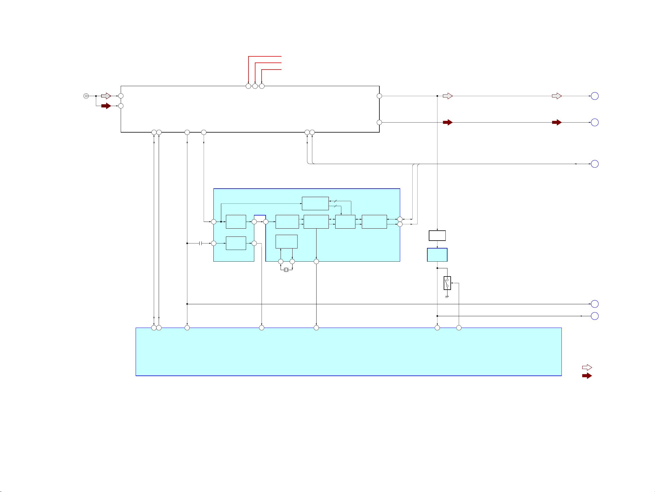
MDX-M690
6-2. BLOCK DIAGRAM – TUNER Section –
FM/AM TUNER UNIT
TUX201
(FM/AM ANTENNA IN)
2
1
ANT-FM
ANT-AM
11
B/U 5V
16
5
VCC 8.5V
VDD 5V
B/U +5V
TU +8.5V
TU +5V
MPX
10
MPX
E
(Page 23)
SDA (EEPROM)
SCL (EEPROM)
17
18
S-METER
14
RDS-DET
9
AM-DET
SDA
SCL
12 13
DATA
CLOCK
RDS DECODER
IC202
PATH
OUT
SC
18
MPTH
2
19
CIN
COMPARATOR
OSCILLATOR
CLOCKED
& CLOCK
OSCI
5
X201
4.332MHz
OSCO
4
MPX
LVIN
57 kHz
BAND-PASS
FILTER
MULTI
DETECTOR
16
20
SIGNAL
QUALITY
DECODER
RDS/RDBS
DEMODULATOR
& DECODER
DAVN
8
5
4
INTERFACE
REGISTER
8
IIC BUS
SLAVE
TRANSCEIVER
SDA
SCL
DATA
CLOCK
9
10
BUFFER
Q202
BAND-PASS
FILTER
IC201
Q203
NOISE DET
DISCHARGE
SWITCH
AM
DATA, CLOCK
F
G
(Page 23)
(Page 23)
10
EEP SIO
11
EEP CKO
53
S-METER
52
MPTH
75
DAVN
SYSTEM CONTROLLER
IC501 (1/3)
50
QUAL
56
NS MASK
S-METER
QUAL
• SIGNAL PATH
(Page 23)
H
(Page 23)
J
: FM
: AM (MW/LW)
2222
Page 23
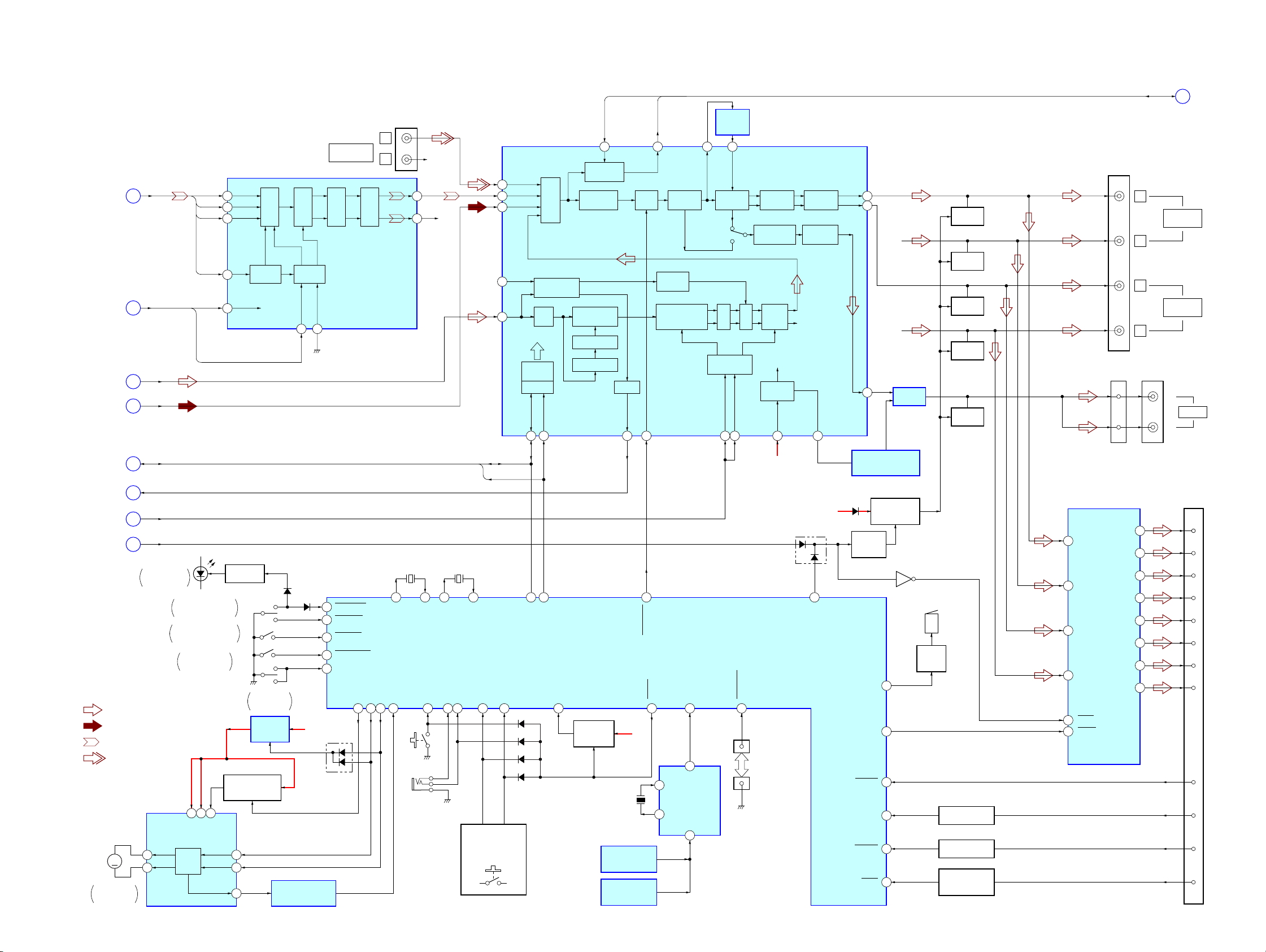
MDX-M690
6-3. BLOCK DIAGRAM – MAIN Section –
DADT,
BCK,
LRCK,
(Page 21)
(Page 21)
(Page 22)
(Page 22)
(Page 22)
(Page 22)
(Page 22)
(Page 21)
A
B
E
F
G
J
H
C
DISC SLOT
ILLUMINATION
FS256
MD-RST,
DEEMP
MPX
AM
DATA,
CLOCK
QUAL
S-METER
ATT
D903
OPEN/CLOSE DETECT
FRONT PANEL DETACH
POSITION DETECT
DISPLAY PANEL
DETACH DETECT
FS256
MD-RST
DEEMP
SW1001
FRONT PANEL
SW1002
• R-ch is omitted due to same as L-ch.
• SIGNAL PATH
: FM
: AM (MW/LW)
: MD PLAY
: BUS AUDIO IN
FRONT PANEL
OPEN/CLOSE MOTOR DRIVE
M
M601
FRONT PANEL
OPEN/CLOSE
IC651
OUT1
3
OUT2
14
MOTOR
DRIVE
45
VCC
LRCK
S1
12
M BATT
VREF
OPEN
CLOSE
RNF
DATADADT
5
BCKBCK
6
LRCK
4
XTI
CLK
1
CONTROL
RSTB
15
LED DRIVE
Q901, 902
CLOSE
OPEN
SW1001
SW1002
SW903
DISC INSERT
DETECT
REGULATOR
REFERENCE
VOLTAGE SWITCH
Q651, 652
11
6
16
INPUT
INTERFACE
D901
Y
S1
+9V
IC652
MOTOR OVER LOAD
IC650, Q650
CONTROL
DM1
17 16
D803
DETECT
FILTER
DIGITAL
MODE
BACK-UP
DM0
B+
CN302 (1/2)
AUDIO IN
NOISE
99
CLOSE-SW
100
OPEN-SW
CENT-SW
101
DETACH_SW
64
111
PACK-IN
D651
BUS
D/A
SHAPER
DIGITAL FILTER,
D/A CONVERTER
IC101
FP_CTRL
40 98 97
L
R
VOUTL
VOUTR
COMVERTER
32.768kHz
73
X1A
I-DET96OPEN-KEY
MOT+
MOT–
LSW60
(OPEN)
(REMOTE IN)
X501
R-CH
12
9
R-CH
X503
3.68MHz
92
93 71
74
X1
X0A
RC-IN172RC-IN048KEY-IN046KEY-IN1
61
J651
LSW1, 2, 5 – 13,
LSW15, 18, 20, 22,
S1 – 4, 7 – 15
DATA
CLOCK
X0
INPUT SELECT,
ELECTRICAL VOLUME
IC305
AUX-L
4
MDL
43
AM/MPX2
9
AMIF
10
12
47
MPX
D508
D501
D503
D505
AM/FM NOISE
LPF
DIGITAL
CONTROL
IIC BUS
SCL
SDA
19 20
IICSIO
BLANKER
INPUT
MULTIPLEXER
IICCKO
KEY_ACK
79
SACLK
21
SPECTRUM
ANALYZER
LOUDNESS
VOLUME
PILOT
CANCELATION
PILOT DET
PLL
KEY ACTIVE
SWITCH
Q501
REMOTE CONTROL
REMOTE CONTROL
SACLK
QUAL
QUALITY
16
X801
4MHz
RECEIVER
D908, IC901
RECEIVER
D70, IC62
SAOUTSAOUT
23
SOFT
MUTE
FORMER
DEMODULATOR
STEREO ADJUST
STEREO BLEND
SM
17
3170
E-VOL-ATT
AD-ON80SIRCS
B/U
+5V
3
4
CONTROL
PULSE
XIN
XOUT
TONE
24
17
SIRCS
SIRCS
9
LOW-PASS
FILTER
IC301
38 33
ACINL
ACOUTL
OUTPUT
SELECTOR
LPF
D/A
CONVERTER
MPIN
LEVEL
14 22 3913
SYSTEM CONTROLLER
IC501 (2/3)
NOSE_SW
62
9
OUT
IN
1
SIRCS
CONTROLLER
IC801
SOFT STEP
FADER
SUB WOOFER
FILTER
HIGH-
CUT
S & H
POWER
SUPPLY
AUDIO
+8.5V
CN604
MAIN UNIT
SIDE
CN2
FRONT PANEL
SIDE
B+
VDD
MIXER
SOFT STEP
FADER
R-CH
CREF
BACK-UP B+
D309
5
ATT
OUTLF
28
OUTLR
27
24
OUTSW
REFERENCE VOLTAGE
D311
MUTING
CONTROL
Q312
BEEP
ST-BY
TEST-IN
ACC-IN
TEL-ATT
ILL-IN
R-CH
R-CH
REGULATOR
IC310-2
BATTERY OFF
MUTE DRIVER
Q310
15
55
84
81
16
95
BUFFER
IC310-1
Q309
BZ501
BUZZER
DRIVE
Q502
ACCESSOR CHECK
MUTING
Q301
MUTING
Q302
MUTING
Q303
MUTING
Q304
MUTING
Q305
Q405
LEVEL SHIFT
Q406
ILLUMINATION
CHECK
Q407
12
14
11
15
22
4
POWER AMP
FL-IN
FR-IN
RL-IN
RR-IN
MUTE
STNBY
CN302 (2/2)
CN301
IC309
1
2
RR+
RR–
FL+
FL–
FR+
FR–
RL+
RL–
SAOUT,
SACLK
L
R
L
R
5
3
21
23
9
7
17
19
D
AUDIO OUT
FRONT
AUDIO OUT
REAR
(L)
SUB OUT
(R)
CN101 (1/2)
(Page 24)
1
9
4
12
2
10
3
11
15
7
13
14
FRONT L+
FRONT L–
FRONT R+
FRONT R–
REAR L+
REAR L–
REAR R+
REAR R–
TEST
ACC
TEL-ATT
ILL
2323
Page 24
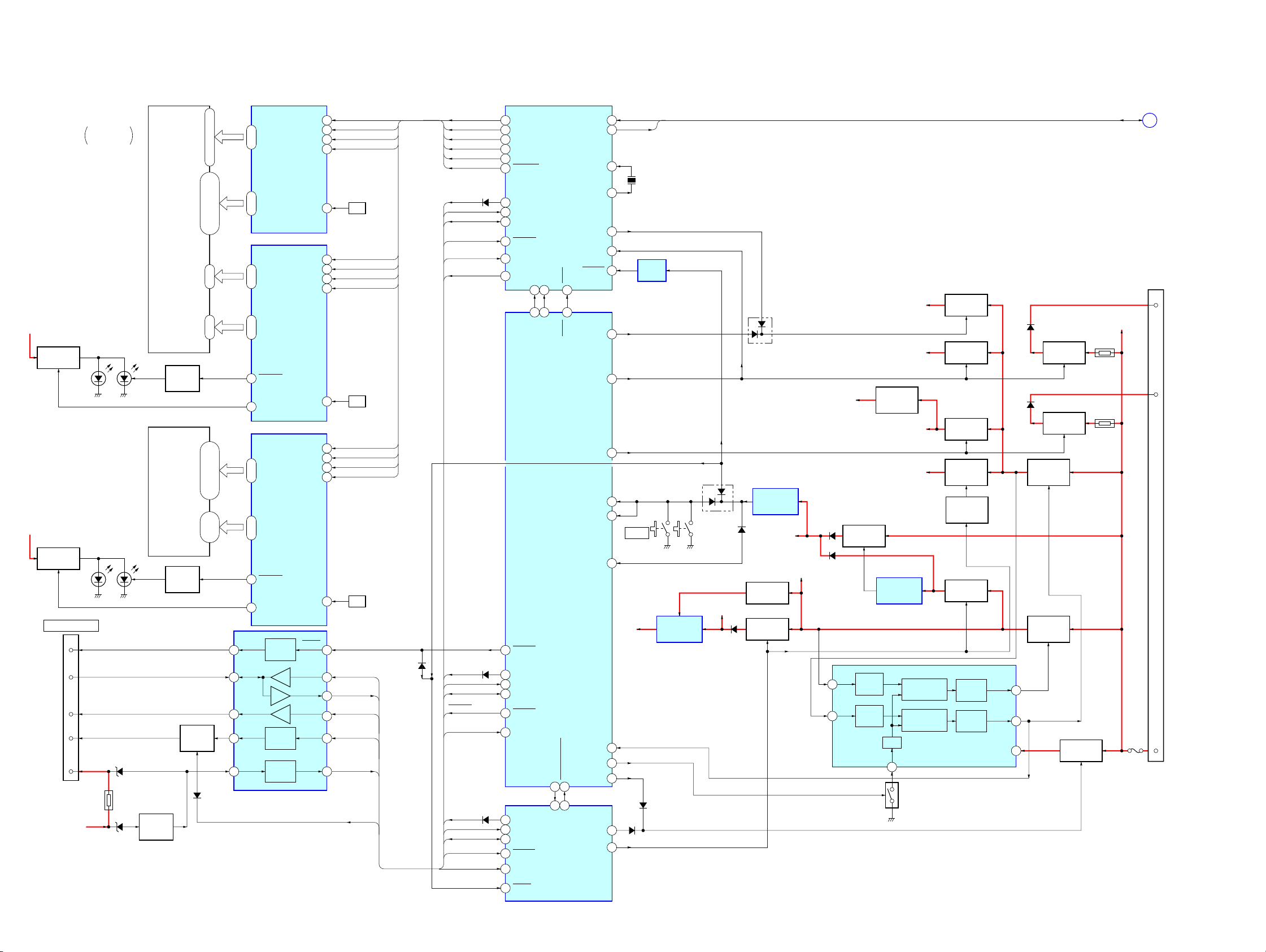
MDX-M690
6-4. BLOCK DIAGRAM – DISPLAY/BUS CONTROL/POWER SUPPLY Section –
LCD B+
LCD B+
LED DRIVE
Q60, 61
LED DRIVE
Q1, 2
BUS CONTROL IN
RESET
DATA
CLK
BUS ON
BATT
BACK-UP B+
LIQUID CRYSTAL
FOR DISPLAY
LSW60
(OPEN)
LIQUID CRYSTAL
(FOR KEY PANEL)
LED3 – LED18,
LSW1, 2, 5 – 13
LSW15, 18, 20, 22
CN601
2
5
4
6
7
TH601
DISPLAY
PANEL
LCD60
DISPLAY
LCD1
D603
D607
LED60,
LED62 – 69
LED1, 2
BATTERY
DETECT
Q603
DIMMER
CONTROL
Q62
DIMMER
CONTROL
Q3
BUS ON
SWITCH
Q602
SEG1 – SEG69
COM1 – COM8
SEG1 – SEG71
SEG1 – SEG8
SEG1 – SEG71COM1 – COM8
D606
1 – 69
115 – 165, 81 – 98
173 – 166
99 – 106, 107 – 114
10 – 80
1, 9 – 2
76, 77, 7 – 37
38 – 59, 61 – 74,
7 – 1
60, 75
SEG1 – SEG69
83 – 76
COM1 – COM8
1 – 71
SEG1 – SEG71
83 – 76
COM1 – COM8
86
DIMMER
85
LED_SW1
1 – 71
SEG1 – SEG71
83 – 76
COM1 – COM8
86
DIMMER
84
LED_SW2
RST
2 13
6 9
4
1 12
3 10
RESET
SWITCH
DATA
CLK
BUS
ON
BUS ON
SWITCH
BATT
BATTERY
SWITCH
SONY BUS INTERFACE
IC601
LCD
DRIVER
IC61
LCD
DRIVER
IC60
LCD
DRIVER
IC1
LCD-DATA
LCD-CLK
LCD-CE0
LCD-INH
OSC
LCD-DATA
LCD-CLK
LCD-CE0
LCD-INH
OSC
LCD-DATA
LCD-CLK
LCD-CE0
LCD-INH
OSC
RESET
DATA IN
DATA OUT
CLK IN
BUS ON
BU_IN
100
99
98
97
96
100
99
98
97
96
100
99
98
97
96
8
11
OSC
C70, R85
OSC
C64, R76
OSC
C5, R41
UNISO
UNISI
UNICKO
BUS-ON
BU-IN
LINKOFF
DATA
CLK
CE1
INH
DATA
CLK
CE0
INH
DATA
CLK
CE2
INH
D612
DATA
CLK
CE0
CE1
CE2
INH
UNISO
UNISI
UNICKO
BUS-ON
BUIN
LINKOFF
UNISO
UNISI
UNICKO
BUS-ON
UNISO
UNISI
UNICKO
BUS-ON
BU-IN
D609
(2/2)
D609
(1/2)
D608
DISPLAY CONTROLLER
LCD_SO/TX
64
LCD_CKO
66
LCD_CE0
LCD_CE1
70
LCD_CE2
71
LCD_INH
69
UNI-SO
97
UNI-SI
98
UNI-SCK
101
BUS-ON
38
BU-IN
34
LINK
50
OFF
SYSTEM CONTROLLER
SYSRST
6
UNISO
18
UNISI
17
UNICLK
19
BUS-ON
14
BUIN
77
UNISO
50
UNISI
49
UNICKIO
48
BUS-ON
61
BU-IN
60
RESET
30
LED_SW1
46
47
115
11657106
IC702
LED_SW2
LED_SW2
IC501 (3/3)
CD_EJECT_OK
585759
21
EJT_KEY
MD MECHANISM
SA-IN
SA-CLK
EXTAL
XTAL
ILLON
SA_ENIN
SYSRES
BOOT
BOOT
FLS_PWON
P-ON
TUNER ON
RSTX
HSTX
RAM-BU
PWM
SHIFT
CD_OPEN_REQ
DDC-ON
LOCK
MDMON
MD-ON
CONTROLLER
IC501 (2/2)
SA-OUT,
BACK-UP B+
TH101
TH102
SA-CLK
F101
D
CN101
(2/2)
5
6
16
(Page 23)
AMP-R
ANT-R
+B
SA-OUT
11260
SA-CLK
1
86
X701
18.432MHz
85
52
32
BUFFER
81
82
83
114
90
86
85
10
37
57
10
65
+3.3V
SW901
RESET
D510
IC701
REGULATOR
IC401, Q401
D511
VCC
+3.3V
D507
S60
(RESET)
DRIVER +5V
D451
RESET SIGNAL
GENERATOR
IC502
D506
B/U +5V
B+ SWITCH
Q402, 403
B+ SWITCH
Q451, 452
D104
LOAD +6V
D105
D106
14
TU +5V
INA1
3
INA2
REGULATOR
Q113
ERROR
AMP
ERROR
AMP
LCD B+
AUDIO +8.5V
+5V
REGULATOR
Q201
TU +8.5V
REGULATOR
CONTROL
IC102, Q116
COMPARATOR
COMPARATOR
OSC
RT
2
SWITCH
B+
PWM
PWM
POWER CONTROL
OSC
Q105
B+ SWITCH
Q109, 112
B+ SWITCH
Q110, 111
B+ SWITCH
Q107, 108
+6V
REGULATOR
Q119
REGULATOR
CONTROL
Q117, 118
B+ SWITCH
Q114, 115
OUTPUT
CIRCUIT
OUTPUT
CIRCUIT
IC101
OUT1
OUT2
VCC
7
10
9
D405
B+ SWITCH
Q401 – 1, 402
D406
B+ SWITCH
Q401 – 2, 404
SWITCHING
REGULATOR
Q106
SWITCHING
REGULATOR
Q103
B+ SWITCH
Q101, 102
2424
Page 25

6-5. NOTE FOR PRINTED WIRING BOARDS AND SCHEMATIC DIAGRAMS
MDX-M690
Note on Printed Wiring Board:
• X : parts extracted from the component side.
• Y : parts extracted from the conductor side.
z
•
•
: Through hole.
f
: internal component.
• : Pattern from the side which enables seeing.
(The other layers' patterns are not indicated.)
Caution:
Pattern face side: Parts on the pattern face side seen from
(Conductor Side) the pattern face are indicated.
Parts face side: Parts on the parts face side seen from
(Component Side) the parts face are indicated.
Note on Schematic Diagram:
• All capacitors are in µF unless otherwise noted. pF: µµF
50 WV or less are not indicated except for electrolytics
and tantalums.
• All resistors are in Ω and 1/
specified.
f
•
: internal component.
4
W or less unless otherwise
• C : panel designation.
Note: The components identified by mark 0 or dotted line
with mark 0 are critical for safety.
Replace only with part number specified.
• A : B+ Line.
• Po wer voltage is dc 14.4V and fed with regulated dc po wer
supply from ACC and BATT cords.
• V oltages are taken with a VOM (Input impedance 10 MΩ).
Voltage variations may be noted due to normal production tolerances.
• Waveforms are taken with a oscilloscope.
Voltage variations may be noted due to normal production tolerances.
• Circled numbers refer to waveforms.
• Signal path.
E : MD PLAY
F : FM
f : AM (MW/LW)
L : BUS AUDIO IN
25
Page 26

MDX-M690
d
• Circuit Boards Location
• FRONT PANEL (DSPL) SECTION
DISPLAY board
• GENERAL SECTION
SW board
SENSOR board
SERVO board
MAIN boar
26
KEY board
SUB MD board
Page 27

6-6. PRINTED WIRING BOARDS – SERVO Section –• See page 26 for Circuit Boards Location.
1 2 3 4 5 6 7 8 9 10 11 12 13 14 15
MDX-M690
SERVO BOARD
A
OPTICAL
PICK-UP BLOCK
(KMS-241C)
B
CN102
R348
R336
C321
13
20
R337
C320
12
C
Q302
BCE
R349
R357
R350
R359
C322
D
IC302
24
R340
25 36
R338
C324
C325
R344
R342
C347
E
C346
R529
R526
C326
R346
+
L302
R527
R528
X501
F
R532
1
+ +
C319
C318
R356
1
C331
R355
48
C329
37
C328
C330
C327
R505
R535
R539
C501
C516
R504
24 1
25
TP2 (SE) TP3 (TE) TP4 (FE)
IC501
R507
G
R506
40
41 64
R511
C10
R516
H
(COMPONENT SIDE)
1
16
C336
R531
R502
R503
R501
C339
IC303
SERVO BOARD
(CONDUCTOR SIDE)
Q301
BCE
C315
R329
C343
C342
R351
R330
76
R331
R353
R352
100
32
17
C349
C311
C314
75 51
IC301
1
IC304
R306
R308
R307
R305
20 11
R301
R302
R304
R303
IC502
110
1
80
TP1
R525
R524
R523
R530
65
R522
R537
R518
R517
2
R538
MAIN BOARD
CN401
111
A
(Page 31)
C310
R328
R327
148
R354
X301
CN101
CN103
R324
5
R360
R325
R320
C308
C350
C351
R335
R333
R334
C506
C316
C505
+
C333
RB503
R540
R542
R534
R533
C515
C504
C514
C513
R520R521
R519
C503
TH501
R510
R512
12
1-680-396-
(12)
IC307
R365
IC305
5
8
C352
4
1
C307
C359
26
22
18
14
C344
L301
C353
C345
+
C309
C358
C317
R362
R367
C301
C356
C357
C511
L501
R332
+
R318
R319
R312
R310
1
10
C106
C510
C305
R317
R316
IC101
R406
29
30
L102
C403
C306
20
11
C109
C108
+
C402
C
Q401
85
R407
14
IC401
D401
AK
C401
R404
R405
E
B
C11
C103C105
L101
+
D301
C102
R101
C101
R402
R361
R401
R104
R403
B
E
AK
R201
C201
C202
BCE
Q402
Q303
BCE
1
5
9
13
C362
+
R202
Q403
C
C363
50
26
25
C104
R102
+
C107
12
1-680-396-
(12)
• Semiconductor
Location
(LIMIT)
Ref. No. Location
D301 G-9
I
D401 F-7
IC101 D-7
M902
(SLED)
MM
J
RED
M901
MM
(SPINDLE)
BLK
111
K
SENSOR BOARD
(COMPONENT SIDE)
(CHUCKING DETECT)
BLK
RED
1-680-397-
12
(12)
SENSOR BOARD
LOADING
DETECT
(CONDUCTOR SIDE)
1-680-397-
12
(12)
IC301 B-6
IC302 D-2
IC303 B-4
IC304 C-6
IC305 G-10
IC307 B-10
IC401 F-7
IC501 G-3
IC502 D-6
Q301 A-5
Q302 C-1
Q303 F-9
Q401 E-7
MM
M903
(LOADING)
Q402 F-9
Q403 E-9
2727
Page 28

MDX-M690
6-7. SCHEMATIC DIAGRAM – SERVO Section (1/2) –• See page 42 for Waveforms. • See page 43 for IC Block Diagrams.
M901
(SPINDLE)
M902
(SLED)
M903
(LOADING)
(LOADING DETECT)
(CHUCKING DETECT)
CN102
20P
(LIMIT)
VCC
J
B
A
VC
I
F
C
D
E
VEE
ILCC
LD-GND
VR(RM-GND)
RM
NC
FCS-
FCS+
TRK-
TRK+
CN901
B1
B2
B3
B4
B5
B6
B7
B8
A1
A2
C322
0.001
A3
A4
CN103
11P
11P
SP-
SP+
SL+
SL-
LO+
LO-
C-SW
GND
E-SW
IN-LIMIT
NC
Q302
2SA1037AK
AUTOMATIC
POWER CONTROL
R348
4.7k
R349
100
C321
0.0068
CSW
ESW
LIMIT
C318
22
6.3V
C331
0.1
B4
C319
22
6.3V
R336
470k
470k
0.022
R337
C320
B1
B3
B2
B6
B7
B8
B5
R351
2.2k
D5
C339
0.01
IN2R
CAPA-
CAPA+
VG
IN4R
GND
C333
0.1
D8
LOADING MOTOR DRIVE
IC305
BA6287F-T1
OUT1
VM
OUT2
VCC
VREF
FIN
D6
IN4F
D7
GND
RIN
C342
0.01
C3 C4
IN2F
VM4
R350
10
R359
10
R357
47
C1
C2
C3
C4
MORFO
MORFI
I
J
VC
A
B
C
D
E
F
PD
APC
APCREF
TEMPI
GND
R353R352
2.2k2.2k
C343
0.01
A1
VM2
VM12
OUT2F
OUT1R
OUT2R
PGND2
PGND3
OUT3R
VM34
OUT4R
OUT4F
PGND4
C1
A3
C2
PGND1
RFO
TEMPR
A2
A4
OUT3F
OPN
SWDT
DT
SW
OUT1F
C329
0.022
R356
10k
0.01
C330
OPO
ADDC
COMPP
RF AMP,
FOCUS/TRACKING
ERROR AMP
IC302
CXA2523AR
XSTBY
XLAT
SCLK
R338 R342 R344
13k 13k 13k
XLAT
SCLK
D4
D3
IN1F
VM1
IN1R
IN3R
IN3F
VM3
D1
D2
2SC2412K-T-146
REFERENCE
REGULATOR
D301
MA8056-M
R355
10k
VDD
PSB
Q303
VOLTAGE
C336
0.01
COMPO
F0CNT
R340
AGCI
VREF
91k
C352
0.1
C328
0.0022
E2
E1
RF
RFAGC
3TADJ
EQADJ
FOCUS/TRACKING
COIL DRIVE,
SPINDLE/SLED
MOTOR DRIVE
IC303
BH6518FS
EJECT
LOAD
PEAK
WBLADJ
VCC
ADAGC
CSLED
R330
470k
BOTM
ABCD
FE
AUX
ADFG
ADIN
ADFM
SE
TE
C347 C324
0.01 0.1
R331
C350
0.1
C351
22
10V
XRST
R361
2.2k
E3
E4
E5
E6
C327
1
C326
0.0047
E7
E8
C325
0.068
R346
56k
100
0.1
C349
E6
L302
C316
C346
C317
22
6.3V
C345
0.01
C344
6.3V
C306C307 C305
0.470.1 0.01
C314
0.1
E8
E7
TP3 TP2
(TE) (SE)
Q301
2SC2712Y-TE85L
PEAK HOLD
R329 R334R333
680 100680
1
C315
SE
TE
DCHG
APC
ADFG
F0CNT
XLRF
CKRF
DTRF
APCREF
D1
D2
0.1
D3
D4
0.1
D5
D6
D7
D8
22
C353
0.1
LDDR
TRDR
TFDR
DVDD
FFDR
FRDR
FS4
SRDR
SFDR
SPRD
SPFD
FGIN
TEST1
TEST2
TEST3
DVSS
EFMO
MNT0(FOK)
MNT1(SHCK)
100
100
100
C356
100p
C357
100p
C358
100p
C359
47p
R303
R302
R301
NT2
NT1
NT0
M
M
M
1024FS OSC
IC304 R354
TC7WU04FU 10k
ADRB
AVSS
MNT2(XBUSY)
MNT3(SLOC)
100
R304
MNT3
ADIOVCAVDD
ADRTSWDT
SCLK
XLAT
100
R305
DT
SRDT
SW
XLAT
SCLK
VCC
C311
0.015
E2
E3
E5
E4
TP4
(FE)
330
R335
FE
AUX1
PEAK
BOTM
ABCD
DIGITAL SIGNAL PROCESSOR,
EFM/ACIRC ENCODER/DECODER,
SHOCK PROOF MEMORY CONTROLLER,
ATRAC ENCODER/DECODER,
DIGITAL SERVO SIGNAL PROCESSOR
IC301
CXD2662R
SRDT
SENS
SQSY
DQSY
XRST
RECP
100
R307
100
R306
C301
0.1
XINIT
SQSY
SENS
XRST
R367
0
R360
0
GND
C310
0.47
CLTV
XINT
R362
150
45MHz
R320
R328
680k
150
E1
R325
1k
100
R332
1k
3.3k
R327
0.0047
R324
C309
RFI
PCO
AVSS
FILI
FILO
DIN0
TX
OSCI
OSCO
XTSL
R308
100
X301
100k
100p
R319
C308
10k
R318
D3
D3
ASYO
AVDD
ASYI
BIAS
MDDT1
D2
D0
D1
XWE
XRAS
A09
XCAS
XOE
DVSS
A11
A08
A07
A06
A05
A04
A10
A00
A01
A02
A03
DVDD
FS256
XBCK
LRCK
DADT
XBCKI
LRCKI
DOUT
DIN1
ADDT
DATAI
D0
D1
XWE
XRAS
A09
A00
A01
A02
A03
C362
0.1
D0
D1
WE
RAS
A09
IC307
MSM51V4400-70TS
A00
A01
A02
A03
VCC
D-RAM
R317
1k
R316
1k
R312
2.2k
R310
1k
VSS
D3
D2
CAS
OE
A08
A07
A06
A05
A04
D2
D0
D1
XWE
XRAS
A09
XCAS
XOE
A08
A07
A06
A05
A04
A00
A01
A02
A03
256FS
BCK
LRCK
DATA
D3
D2
XCAS
XOE
A08
A07
A06
A05
A04
L301
10µH
1
2
3
4
5
(Page 29)
6
7
C363
0.1
• Voltages and waveforms are dc with respect to ground
under no-signal conditions.
no mark : MD PLAY
2828
: Impossible to measure
∗
The components identified by mark 0 or dotted
line with mark 0 are critical for safety.
Replace only with part number specified.
8
9
10
Page 29

6-8. SCHEMATIC DIAGRAM – SERVO Section (2/2) –• See page 42 for Waveforms. • See page 43 for IC Block Diagram.
MD-ON
P
M
E
E
D
EJT-KEY
LIMIT-IN
CC-XINT
UNICKIO
LINKOFF
P
EM
T
R507
4.7k
MD-LAT
BUS-ON
MD-RST
MD-CKO
UNIREQ
EE-SIO
EE-CKO
DO-SEL
T
N
C
A
BU-IN
MD-SI
UNISO
UNISI
MD-SO
EE-CS
R530
2.2k100k
C-SW
SQSY
SENS
R512
100k
R511
150k
R510
0
TH501
R525
TP1
C504 R524 R522
R102
10k
C104
0.1
256FS
LRCK
DATA
BCK
1
MNT0
SRDT
MNT1
SENS
MNT2
SQSY
MNT3
XINIT
DIGITAL FILTER,
D/A CONVERTER
IC101
PCM1718E/2
XTI
XTO
DGND
CLKO
VDD
MUTE
LRCK
DM1
DATA
DM0
BCK
RSTB
ZERO
MODE
D/CR
VOUTR
D/CL
VOUTL
AGND
VCC
C105
0.1
LEVEL SHIFT
IC502
HD74HC244FP-EL
VCC
GND
GND
GND
6.3V
10
C202
C103
0.01
C102
R104
10
1k
6.3V
C108 L101
0.01
C107
0.01
MNT0
SRDT
MNT1
SENS
MNT2
SQSY
MNT3
XINIT
R101 C101
10k 0.0022
C106
4.7
6.3V
R501
LOAD
EJECT
MDMON
C201R201R202
0.002210k1k
C109
4.7
10µH
6.3V
L102
10µH
ESW
LOCK
1k
R502
1k
R503
1k
R531 C516
100k 0.1
R542
100k
R539
100k
R504
1k
R540
100k
TIN3
TIN4
TIN5
TIN6
TIN7
LOAD
EJECT
MDMON
E-SW
AG-OK
ADJ-OK
DFCTSEL
DPLLSEL
EMPHSEL
LOCK
2M/4M
0.1 1k 1k
0
1
2
2
1
0
T
T
T
T3
U
U
U
U
IN
IN
IN
T
T
T
O
O
O
O
T
T
T
T
MD MECHANISM
CONTROLLER
IC501
CXP84340-231Q
T
0
T
N
M
NT0
MNT1
M
L
1
2
3
E
A
T
T
T
S
T
N
N
N
E
X
R
M
E
M
M
R532
100
NT2
M
R505
MNT3
C501
100p
C
D
D
N
D
O
V
M
T
TS
L
S
A
T
S
X
V
TX
C503
X501
10MHz
1k
R535
100k
1k
R523
E
O
O
T
K
U
TS
C
S
T
T
-M
A
TS
ERROR-PWM
EF
S
R
IT
VS
V
EX
T
A
A
IN
0.1
R506
100k
MDX-M690
CN101
BUSON
UNISI
UNISO
UNICK
SYSRST
LNKOF
C514
0.22
C515
0.1
R521
100
R537
100
BUSON
BUCHK
RB503
SQSY
EJKY
LIMIT
XINIT
SENS
SRDT
UNISO
UNISI
UNICK
LNKOF
1k
X4
SYSRST
R520
100
R519
100
R518
100
R517
100
R516
100
R526
2.2k
R527
2.2k
R528
2.2k
R529
2.2k
DT
ST
XR
SW
SCLK
XLAT
R534
100k
CSW
0
C513
R533
100k
R365
0.1
BUCHK
EJKY
LOCK
MDMON
C511
0.1
100k
R538
C506
C505
22
0.1
10V
C510
0.22
30P
BUSON
BUS-SI
BUS-SO
BUS-CLK
SYSRESET
LINKOFF
B/UCHECK
EJECT
ATT
LOCK
MD-ON
MECHA-ON
L501
C10
470p
C11
0.001
BU5V
NC
U COM GND
NC
L-CH
AUDIO GND
R-CH
LOAD6V
NC
NC
NC
NC
D-GND
NC
NC
DRIVER5V
DRIVER-GND
DRIVER-GND
(CHASSIS)
(Page 34)
(Page 28)
R407
100k
Q402
2SB1132
D401
DTZ-TT11
-3.0B
2
3
4
5
6
7
8
9
10
Q401
2SD1664
R405R406R404C401
1k10k1000.22
+3.3V
REGULATOR Q402,403
+3.3V
REGULATOR
IC401
C402
0.01
NJM4580E(TE2)
VCC
B+ SWITCH
GND
C403
0.1
R403
4.7k
Q403
UN2211-TX
R401
10k
R402
4.7k
• Voltages and waveforms are dc with respect to ground
under no-signal conditions.
no mark : MD PLAY
2929
: Impossible to measure
∗
Page 30

MDX-M690
6-9. PRINTED WIRING BOARD – MAIN Section (1/2) –• See page 26 for Circuit Boards Location.
• Semiconductor Location
Ref. No. Location
D104 L-8
D107 F-2
D109 H-9
D202 D-13
D203 D-13
D204 I-9
D205 H-9
D302 C-7
D303 C-7
D304 C-6
D309 H-8
D311 D-7
D404 D-4
D406 E-5
D407 E-6
D503 I-6
D505 I-6
D506 K-8
D507 K-8
D509 J-8
D511 I-5
D602 G-6
D604 H-6
D605 H-6
D606 H-5
D609 H-7
D612 I-7
D650 J-2
D804 L-10
D807 I-10
IC101 G-3
IC102 F-2
IC201 I-10
IC202 G-13
IC301 H-9
IC302 G-9
IC305 F-10
IC310 E-12
IC501 J-6
IC502 L-9
Ref. No. Location
IC650 K-3
IC651 K-4
IC652 J-2
IC702 J-13
IC801 J-9
Q101 H-2
Q102 G-2
Q105 G-3
Q107 I-4
Q108 I-4
Q109 L-9
Q110 G-4
Q111 G-4
Q112 L-8
Q114 F-2
Q115 F-2
Q116 F-2
Q117 H-1
Q118 H-1
Q201 E-13
Q202 I-11
Q203 H-9
Q301 C-10
Q302 C-10
Q303 C-11
Q304 C-11
Q305 C-12
Q309 D-8
Q310 D-8
Q312 E-8
Q401 E-5
Q402 E-6
Q404 E-6
Q405 E-6
Q406 E-7
Q407 E-7
Q452 F-5
Q602 H-5
Q651 K-3
Q652 K-3
1
2 3 4 5 6 7 8 9 10 11 12 13 14
A
IC102
R133
Q102
C125
R138
R134
C123
C124
R101
D109
R103
R102
(COMPONENT SIDE)
Q114
R132
R137
Q115
Q116
D107
R106
R104
C103
Q101
D650
C651
R653
R136
R113
C108
C105
C106
C107
C650
8
IC650
R654
R135
C110
R111
R107
C120
R131
5
4
C652
R662
R659
(CHASSIS)
Q105
R116
IC101
R114
R112
C111
C119
R652
R655
R651
R650
R658
R379
R419
R51
R510
C512
D302
D311
R512
D609
R550
C344
C386
C510
R513
R425
R301
R312
Q305
R343
R364
R361
C350
C349
R360
Q202
R809
KEY BOARD
CN1
C359
C358
Q304
R373
R372
R374
CN604
R326
C365
C369
R376
C364
Q303
IC310
R716
C709
C302
R389
R717
C703
R811
R810
R813
C366
R347
R346
C383
Q302
C384
R348
R349
R356
Q301
R344
R358
R357
C357
C388
Q310
C337
C348
C385
C387
Q309
R377
Q312
C373
IC305
R335
Q112
R313
D507
D506
D104
4
C307
4
R307
IC801
R544
R128
C315
C314
IC301
R207
R545
R127
C222
D204
3
R818
Q109
8
5
C215
R213
5
D205
C214
R340
R306
8
IC302
R339
R330
R305
Q203
5
R208
8
R830
2
IC502
1
R815
IC201
R214
C211
R820
R819
C813
C814
R823
R807
R803
R802
D804
R821
C223
R808
R804
C338
4
R827
R206
R816
R822
D807
R212
R817
C341
C345
R363
C353
C212
C210
C213
R806
R828
R316
C306
D309
R515
R546
R517
D509
C
R304
4
5
R718
R723
R814
R812
8
R215
C224
R719
IC702
(CHASSIS)
C227
C704
C301
R302
C230
IC202
R724
C710
D203
D202
C208
Q201
C228
C229
R725
1-681-372-
C226
R705
R704
R708
FB707
(CHASSIS)
R201
R204
L201
R221
C219
R216
R712
R711
R703
11
(11)
R424
R110
R117
C657
1
5
Q107
R129
D404
Q111
R130
Q108
R123
IC652
IC651
Q652
Q651
R656
R406
5
8
R141
R124
Q110
R423
D602
R543
R542
Q404
R417
D604
D505
C405
Q402
D605
D503
R416
IC501
R540
R535
R405
4
1
Q401
D406
Q452
C128
R459
R140
R504
R602
R608
D606
Q602
R553
R552
D511
R502
R551
R521
R511
R516
C514
C513
R519
R520
R528
D407
R414
R533
C502
R415
Q405
C406
D304
D303
R402
R422
R418
R413
R420
R421
Q406
Q407
D612
R503
C505
R509
R538
(Page 38)
MAIN BOARD
B
C
D
E
F
G
H
Q118
Q117
I
J
K
L
3030
Page 31

6-10. PRINTED WIRING BOARDS – MAIN Section (2/2) –• See page 26 for Circuit Boards Location.
MDX-M690
A
B
C
D
E
F
G
H
I
J
K
L
1
SUB OUT (MONO)
(L)
(R)
(CONDUCTOR SIDE)
3
2
1
(CHASSIS)
2 3 4 5 6 7 8 9 10 11 12 13 14 15 16 17
MAIN BOARD
TUX201
FM/AM TUNER UNIT
C201
R202
R203
R209
R217
BZ501
R548
Q502
R547
C202
C231
C225
C205
C206
R713
R222
R220
FM/AM
ANTENNA IN
2
1
CN201
C207
X701
C705
BP701
C711
C319
R726
R327
C320
C801
C318
CN302
REAR
C323
C324
C317
C380
D806 D805
C363
R303
AUDIO OUT
R329
R338
C305
C378
C308
R506
R514
R527
R537
R526
R549
R507
CN305
D405
Q603
D603
C511
X503
Q451
R458
F101
CN101
C509
D510
D508
C517C516
D607
C506
C507
R403
R605
R604
R410
TH101
C403
R409
R404
R401
R411
C121
C113
C112
L102
R108
R139
X501
C508
R115
C381
C116
D502
R505
R660
C658
D652
C659
R109
C382
D504
R601
TH102
C122
C101
C109
R105
C104
L101
R122
L103
L105
C656
D651
R661
C653
BLK
WHT
RED
BLU
CN602
FRONT
L501
R391
R805
CN603
R397
C329
R451
C347
C361
CN401
C407
C457
C602
R501
R500
R529
R523
R522
R539
R518
R382
C454
D451
R454
IC601
C503
C501
R508
Q501
R536
R541
D803
D301
R393
C451
R380
D608
SUB MD
B
BOARD
R317
R314
C376
C377
C379
R210
R211
X801
D802
C57
R324
R325
C316
C332
R205
CN304
D305
D306
D308
D307
R395
R801
C304
C303
C515
R825
C374
C371
R309
R310
R308
C313
C325
R345
C333
C209
C218
R824
IC309
BUS
AUDIO
IN
L R L R L R
C58
C216
R218
X201
C375
C328
C217
R219
C221C220
C701
R714
R715
R342
L701
C343
R341
CN301
R311
C360
IC701
C708
C706
R702
C707
R727
R709
R701
D801
C802
R722
C712
FB706
(Page 36)
D102
C117
C655
D401
R126
L104
D101
R657
CN601
TH601
C115
Q650
C660
CN601
BUS CONTROL
IN
C603
R603
D106
Q106
R120
R125
C118
BP601
1-681-372-
D501
R119
J651
(REMOTE IN)
RL+ RL–
FL+ FL–
FR+ FR–
1 9
2 10
3 11
4 12
5 13
6 14
7 15
8 16
NC BATT
NC NC
GRN/BLK
WHT/BLK
GRY/BLK
VIO/BLK
WHT/BLK
GRN/BLK
VIO/BLK
GRY/BLK
LIGHT BLU
BLU/WHT
YEL
BLK
NC
YEL
FRONT PANEL DETACH
SW1002
GRN
TO
CN101
WHT
R606
D611
R607
D610
L401
D105
Q103
R118
R121
C126
SERVO BOARD
CN101
M601
PANEL
OPEN/CLOSE
M
11
(11)
A
WHT
RED
BLK
BLU
Q113
C127
Q119
(Page 27)
SW BOARD
GRY
VIO
WHT
GRN
VIO
GRY
BLU
RED
BLK
RED
BLU
ANT REM
FRONT PANEL
OPEN/CLOSE DETECT
SW1001
RR+ RR–
ACC GND
SW1001
ATT
AMP REM
SW1002
POSITION DETECT
1-681-375-
• Semiconductor
Location
Ref. No. Location
D101 F-14
D102 H-14
D105 E-15
D106 F-14
D301 C-9
D305 C-9
D306 C-8
D307 C-8
D308 C-8
D401 C-14
D405 E-12
D451 F-11
D501 D-14
D502 J-13
D504 J-13
D508 I-12
D510 I-12
D603 H-12
D607 H-12
D608 H-10
D610 C-15
D611 C-15
D651 J-13
D652 K-13
D801 K-5
D802 L-7
D803 L-11
D805 K-6
D806 K-5
IC309 B-9
IC601 H-11
IC701 J-4
Q103 F-15
Q106 G-14
Q113 F-15
Q119 G-15
Q451 F-12
Q501 J-11
Q502 I-2
Q603 H-12
Q650 J-14
11
(11)
3131
Page 32

MDX-M690
R310
C304
C205
C343
C315
C335
R390
C325
C384C383
R356
R357
R358
R361
C380
C379
C378
C377
C376
C209
R376
C369
R373
C360
C363
R372
C350C349
R363
C359
R374
C358
C333 C332
R345
C375
C338
C341
C345
C353
R340R339
R330
R305 R306
C314
C306R316
C303 R308 R309
C307 R313
R307
R204
Q201
C207
D202
D203 C208
L201
R202
R203
C206
R201
R222
C231
C202
C201
R221
R360
R364
TUX201
R209
C216
R217
C225
X201
R219
R215 C224
IC202
R216
C220
C221
C217
C219
R218
R220
C228
C226
C229
C230 C227
IC301 IC302
R389
R335
IC305
C364
C365
IC201
R208
C214
C215
D204
R207
R213
D205
C222
R205
Q202
C211
C210
C212 C213 R206
R210
R211 R212 C218
C223 R214
IC310
Q203
CN202
10k
0.012
0.1
0.1
0.1
1
47k
10
16V
0.220.22
220
220
220
220
100p
100p
100p
100p
100p
1
50V
47k
100p
0
220 10V
0.01
0
0.0220.047
100k
1
47k
1
11
0
0.01
1
1
0.01
0.0047
10k10k
10k
00
0.1
0.001510k
0.012 10k 10k
0.0015 10k
10k
470
2SD1664
47
6.3V 1SS355
MA8051-L 0.1
0
0
0
0.1
10
0
47
16V0.1
18p
0
6.8k
220
TUX-020
0
47
10V
10
0.1
4.332MHz
1k
470k 0.1
SAA6588T/V2
470
56p
56p
470p
0.001
1.5k
10
330p
0.1
2.2
560p 0.0022
NJM4580V NJM4580V
0
10k
TDA7406T
0.47
0.0047
BA4558F
100k
10p
0.47
MA153
100
1M
MA8051-L
0.047
10k
2SC2412K
0.1
0.001
0.001 0.001 2.2k
10k
2.2k 2.2k 0.1
470p 100
NJM4580V
KRC102S
2P
1A
2A
3A
4A
5A
6A
7A
9A
10A
11A
12A
13A
14A
1B
2B
3B
4B
5B
6B
BUS-R
BUS-L
BUS-GND
SDA
SCL
FL
FR
RR
RL
L
-C
H
G
N
D
R
-C
H
TRDA
TRCL
DAVN
MPT
S-METER
SAOUT
SACLK
C
1
C
2
C
3
C
1
C
2
C
3
AM_DET
RDS_DET
MPX
SDA
SCL
S_METER
GND
AM_IF
GND
FM_AGC
AM-ANT
FM-ANT
SDA
SCL
EEPROM
SW_SHIFT
B/U 5V
TUNER 5V
GND
VCC
ANT-GND
VCC-8.5V
GND
VCC
VD
D
CREF
ACOUTL
XR_R
AUX_R
PD-
AUX_L
PAUSE
PHONE
TIM
NAVI
AM/MPX2
AM IF
CMPX
MPX1
LEVEL
MPIN
MPOUT
QUAL
DGND
SD
A
SCL
SACLK
SAOUT
OUTSW
OUTRR
OUTRF
OUTLR
OUTLF
MIXINRF
MIXINRR
MIXINLR
MIXINLF
ACINL
SW
IN
ACIN
R
ACO
UTR
SW
ACOUT
CDL
CDR
MD
R
M
DL
XR_L
SM
GND
VCC
GND
VCC
M
RO
M
PTH
SDA
SCL
TCON
OSCI
VSSD
VDDD
DAVN
CIN
VREF
MPX
VSSA
VDDA
AFIN
M
AD
PSW
N
SCOUT
LVIN
(CHASSIS)
FM/AM
ANTENNA IN
()
FM/AM TUNER UNIT
OSCO
RDS DECODER
LOW-PASS
FILTER
LOW-PASS
FILTER
INPUT SELECT,
ELECTRICAL VOLUME
BAND-PASS FILTER
BUFFER
SWITCH
DISCHARGE
NOISE DET
BUFFER,
REFERENCE
VOLTAGE
REGULATOR
6-11. SCHEMATIC DIAGRAM – MAIN Section (1/4) –• See page 42 for Waveform. • See page 43 for IC Block Diagrams.
(Page 33)
(Page 35)
• Voltages and waveforms are dc with respect to ground
under no-signal (detuned) conditions.
(Page 34)
no mark : FM
( ) : MW
3232
〈〈 〉〉 : LW
Page 33

6-12. SCHEMATIC DIAGRAM – MAIN Section (2/4) –
MDX-M690
(Page 32)
(Page 34)
1A
2A
3A
4A
5A
6A
7A
R346
0
R347
0
R349
0
R348
0
FL
FR
RL
9A
10A
11A
12A
ATT
R380
47k
KRC102S
BUZZER
BZ501
R547
1k
Q502
DRIVE
L501
22µH
BEEP
R548
15A
16A
17A
18A
19A
0
C515
100
6.3V
MA152WK
RR
D309
Q309
2SK1133
INVERTER
S
Q312
KRC104S
Q310,312
MUTING CONTROL
R425
2.2k
R303
0
R311
0
0
R343
R344
0
C329
KRA104S
R379
47
POWER AMP
IC309
TA8268AH
VCC VCC
ST-BY
MUTE
R391
1k
C385
C337
0.47
22p
R393
1k
C386
22p
R395
1k
C387
22p
R397
1k
C388
22p
R377
0
L701
10µH
Q310
D311
1SS355
C374
47
16V
C344
0.47
C348
0.47
C357
0.47
V
50
1
71
3
C
R382C373
4701
RL
IN1
FL
IN2
RR
IN3
FR
IN4
AC-GND
S-GND
C347
0.47
50V 100p
5V
V
6.3
F
Q114
2SB1132
30
3
0.047
21
1
122
C
54
Q114,115
C
106
R1
LEVEL SHIFT
D
S
1
OUT1+
P-GND1
OUT1-
OUT2+
P-GND2
OUT2-
OUT3+
P-GND3
OUT3+
OUT4+
P-GND4
OUT4-
TAB
N.C
SVR
C361
10
C366
16V
D105
MA735
R132
10k
Q115
R135
KRC102S
2.2k
R136
2.2k
062-L
A8
M
7
10
D
Q113
2SD2164
REGULATOR
C124
0.01
0.1
R133
15k
KRC104S
Q116
REGULATOR CONTROL
RL+
D301
CRS02
D302
RL-
CRS02
FL+
D303
CRS02
D304
FL-
CRS02
D305
CRS02
D306
CRS02
D307
CRS02
D308
CRS02
REGULATOR
CONTROL
IC102
RN5VD53AA
CD
OUT VDD GND
R137
47k
Q116
B1
B2
B3
4.7k
R417
6
B4
N.C
4.7k
41
R
TEL_MUTE
C123
0.1
TEST
D1
D3
D5
ACC
D2
D4
ILLM
D1
D2
D3
D4
D5
D405
1SR154
Q401,402,404
B+ SWITCH
D406
1SR154
ACCESSORY
2SC2412K
ILLUMINATION
R423
10k
2SC2412K
CHECK
Q407
CHECK
C305
R314
10
100
16V
Q301-305
MUTING
Q302
R325
R326
R338
100
R341
100
Q406
LEVEL
SHIFT
100
100
Q401(1/2)
UPA1853GR
R415
4.7k
1SS355
S
KRC103S
S
KRC103S
D407
DTC314TK
DTC314TK
DTC314TK
Q402
Q401(2/2)
UPA1853GR
Q404
R421
KDZ6.8V10k
Q303
Q304
D404R424
C316
10
16V
C317
10
16V
C324
10
16V
C328
10 16V
Q405
2SC2412K
R413
BUS-L
BUS-GND
BUS-R
DTC314TK
47k
C406 R414R420
1 47k47k
Q301
DTC314TK
R422
100k
R403
R410
R404
R409
JW302
JW301
C403
3300
R302
10k
R312R304
R317 C308
47k 100p
R324
47k
R327 C318
47k 100p
R329 C323
47k 100p
R342
47k
Q305
TH101
R405
10k
TH102
R406
10k
R419
10k
R418
10k
C407
4.7
35V22k
10k
10k
10k
10k
16V
1k10k
01
D4
C313
100p
R402
R401
1N5404TU
C58
0.1
C301R301
100p1k
C302
100p
CN301
C319
3P
100p
C320
100p
B1
B2
B3
B4
A4
A3
A2
A1
FL+
FL-
RL+
RL-
A1
A2
A3
A4
AMP-R
TEL-MUTE
1k
2.2k
R411
2.2k
L401
250µH
ANT-R
JW401
(CHASSIS)
CN302
6P
L
BUS AUDIO IN
R
L
REAR
R
AUDIO OUT
L
FRONT
R
C57
(CHASSIS)
100p
(CHASSIS)
(L)
SUB OUT
(MONO)
(R)
RL-
FL-
FR-
RR-
RL-
BATT
GND
BATT
F101
10A
RL+
FL+
FR+
RR+
FL+FL-
RL+
RR+RR-
FR+FR-
ATT
AMP REM
ANT REM
ACC
GND
ACC
ANT REM
L-CH
GND
R-CH
CN304
4P
CN305
4P
CN101
16P
FL+
FL-
RL+
RL-
RR+
RR-
FR+
FR-
ILL
ACC
TEST
GND
1C
2C
3C
4C
5C
6C
7C
8C
9C
(CHASSIS)
(Page 35)
• Voltages and waveforms are dc with respect to ground
under no-signal (detuned) conditions.
no mark : FM
3333
[ ] : MD PLAY
Page 34

MDX-M690
6-13. SCHEMATIC DIAGRAM – MAIN Section (3/4) –• See page 42 for Waveforms. • See page 43 for IC Block Diagrams.
(Page 32)
(Page
29)
CN401
30P
DRIVER-GND
DRIVER-GND
DRIVER5V
D-GND
LOAD6V
AUDIO GND
U COM GND
MECHA-ON
MD-ON
EJECT
B/UCHECK
LINKOFF
SYSRESET
BUS-CLK
BUS-SO
BUS-SI
BUSON
B
1
NC
NC
B/U-CHE
C457C454
0.1330
6.3V
R51
1k
BUSCK
SUSSO
BUSSI
BUSON
NC
NC
NC
NC
R-CH
L-CH
NC
NC
BU5V
LOCK
ATT
R-CH
GND
L-CH
B
2
R451
0
C451
22
16V
D451
1SR154
R454
0
D510
1SS355
Q451,452
B+ SWITCH
2SB1132
KRC102S
Q451
R459
1k
Q452
R458
10k
1SS355
B
B
3
4
D511
MPT
S-METER
R502
R551
B
5
KEY-IN0
KEY-IN1
R553
1k
1k
1k
R552
1k
B
6
TRCL TRDA
BUSON
I
I
S
S
U
U
ISO
N
k
U
1
0
R512R509
1
5
3301k
R
I
O
T
T
IS
IS
N
N
-A
U
U
L
E
T
SYSTEM CONTROLLER
IC501
MB90574BPMT-G
-322-BND
N
V
A
A
0
1A
D
X
X
z
k
H
0
7
K
4
8
6
1
.7
1
2
5
3
R
1
0
5
C510
X
0.1
p
p
8
5
1
1
9
8
0
0
5
5
C
C
VN
A
D
TX
N
O
RX
US
B
k
k
k
1
1
1
7
5
0
3
1
1
5
1
5
5
5
5
R
R
R
R
X
X
N
P
O
R
T
E
O
K
IO
-
E
S
B
-C
-S
U
P
P
B
E
E
E
E
K
C
A
N
_
-IN
IN
-O
O
O
Y
C
N
C
C
U
D
E
C
B
A
K
N
A
R514
47k
R516
0
SYSRST
k
1
O
C
N
N
O
W
P
_
S
L
F
-TX
D
-RX
D
T
O
C
C
C
N
V
-IN
T
N
S
-O
E
T
P
R519
R518
O
O
O
T
S
C
C
C
T
R
A
N
N
N
S
Y
S
TUNER-ON
CDMD-SEL
CLOSE-SW
U
-B
X
2
1
0
M
T
D
D
D
A
S
R
H
M
M
M
C511R520
2.21k
220
4.7k
LED_SW2
LED_SW1
PACK-IN
DSTSEL2
DSTSEL1
CENT-SW
OPEN-SW
4V_SEL
BEEP
R539
100k
TEL_MUTE
ATT
O
C
N
NCO
VSS
NCO
NCO
NCO
NCO
NCO
NCO
NCO
BOOT
NCO
MOT+
MOT-
I-DET
ILL-IN
VCC
X1
X0
VSS
X
T
S
R
C513C514
0.10.001
C512
0.001
R529
100k
R522
0
R523
0
R535
100k
R540
100k
MOTOR+
MOTOR-
I_DET
ILLM
R542
100k
R527 C516
6.8k
X503
3.68MHz
R537R536R528
100k100k100k
TEST
SW2
SW1
PACKIN
R538
100k
SENSON
BOOT
R533
100k
CENTER
OPEN
CLOSE
R541
100k
R543
100k
27p
C517
27p
ACC
V
GRES
IC502
XC61CN4102MR
R544
470k
D506
1SS355
MA152WK
D509
1SS355
R546
100k
R545
100k
D507
UCK
CK
CS
U
IR
S
O
O
R503
0
C505
0.001
C502
0.001
C501
0.0047
R500
0
R501
22k
C503
0.001
D503D505
1SS3551SS355
D508 R508
1SS355 100k
E-VOL-ATT
NCO
VSS
C
NCO
NCO
SHIFT
DVCC
DVSS
FP_CTRL
NCO
AVCC
AVRH
AVRL
AVSS
KEY-IN0
KEY-IN1
RC-IN0
NCO
QUAL
NCO
MPTH
S-METER
VCC
ST-BY
NS-MASK
DDC-ON
CD_EJECT_OK
CD_OPEN_REQ
NCO
R521
0
O
C
C
C
N
N
N
W
S
_
N
E
Y
E
S
E
S
P
S
O
V
O
-K
N
k
0
0
1
6
-KEY
2
5
E_SW
R
OS
PEN
N
O
O
O
O
O
C
C
C
N
N
N
W
S
_
H
C
A
M
O
T
E
C
W
P
D
N
C506
470p
k
0
0
1
k
0
9
1
4
H
5
6
R
0
5
R
ETAC
D
O
O
O
S
C
IR
S
O
C
N
k
0
1
7
0
5
R
K
C
C
C
C
L
N
N
N
N
IC
N
U
-W
A
L
1
H
C
D
S
A
-IN
O
-S
-S
L
C
C
F
IIC
IIC
R
N
p
0
0
1
7
0
5
C
CL
DA
S
S
15A
16A
17A
18A
19A
1D
2D
3D
4D
6D
7D
8D
9D
10D
11D
12D
13D
14D
15D
16D
17D
18D
19D
(Page 33)
(Page 35)
CONTROL IN
R603
100
Q602
KRA104S
BUS ON
R602
100
B+
(CHASSIS)
BUS CLK
BUS DATA
BUS ON
GND
R601
47k
R606
100
R607
100
BP601
CN601
8P
BUS
J651
(REMOTE IN)
SWITCH
R604
TH601
2.2k
V
V
8
8
1
1
9
Z
Z
2
7
D
D
A
K
K
M
2
4
0
0
5
6
6
0
C603
6
D
D
D
220
16V
C660
0.01
D606
1SS355
SONY BUS
IC601
BA8270F
INTERFACERESET
BUS
VCC
ON
RESET
D603
MA8068-M
Q603
KRC102S
BATTERY
DETETCT
RST
BATT
CLK
VREF
DATA
GND
D607 R605
KDZ18V 1k
BUS ON
CLK IN
BU_IN
DATA
IN
DATA
OUT
C602
0.01
D611 D610
KDZ6.8V KDZ6.8V
LNKOFF
D501
1SS355
Q501
KRA102S
KEY ACTIVE SWITCH
KRC103S
MOTOR
OVER LOAD
DETETCT
R504
10k
ET
I_D
Q650
2SC2412K
R651R650
18k10k
Q651
Q651,652
REFERENCE
VOLTAGE SWITCH
2SA1037K
R652
1k
MOTOR
OVER LOAD
DETETCT
Q652
IC650
NJM2904V
R653
100k
C651
C650
0.1
R657R655
33k22k
C653
0.1
+9V REGULATOR
IC652
FRONT PANEL
OPEN/CLOSE
MOTOR DRIVE
IC651
BA6288FS
0.1
R654D650
5.6kMM3Z6V8T1
C652
0.1
R659R658
3.33.3
R656
3.3
R662
3.3
PQ09DZ1U
C655
47
10V
MA152WK
R660D651
D652
MA152WA
C659C658C656 C657
0.10.10.1 0.1
D612
1SS355
1SS355
D608
USO
D609
MA152WK
R608
10k
SYSRST
B/U-CHE
BUSON
BUSON
BUSCK
BUSSO
UCK
UNISO
BUSSI
USI
SIRCS
MOTOR-
100
R661
100
MOTOR+
E1
E3
SIRCS CONTROLLER
IC801
RRX9000-0401R
E2
R818
47k
R819 R830
100k 100k
R820
100k
R821
100k
R822
100k
C813
1
R825
R824 D807
1M
470 1SS355
R823
1k
X801
C814
0.1
4MHz
• Voltages and waveforms are dc with respect to ground
under no-signal (detuned) conditions.
no mark : FM
3434
[ ] : MD PLAY
Page 35

6-14. SCHEMATIC DIAGRAM – MAIN Section (4/4) –• See page 42 for Waveform. • See page 43 for IC Block Diagram.
MDX-M690
(Page 33)
(Page 32)
(Page 34)
SW1001
FRONT PANEL
OPEN/CLOSE
DETECT
SW1002
FRONT PANEL
DETACH POSITION
DETECT
(Page 39)
(Page 37)
)(
)(
CLOSE
2C
1C
3C
5C
4C
6C
7C
8C
9C
(4/4)
13A
14A
1D
2D
3D
Q107,108
B+ SWITCH
R139
2SB1132
0
4D
Q119
2SD2394-G
+6V
REGULATOR
C126
CLOSE
CN602
M-
M+
GND
CLOSE
OPEN
CENTER
10
16V0.1
E1
6P
E2
E3
C127
6D
7D
8D
9D
10D
11D
12D
13D
14D
15D
16D
17D
18D
19D
CN603
11P
R801
1k
RX(SI)
TX(SO)
FLS_W
D803
1SS355
CLOSE
NC
RESET
LCD_9V
GND
SIRCS
NC
DICS_IN
M601
FRONT PANEL
()
OPEN/CLOSE
CENTER
CLOSE
GND
OPEN
OPEN
(CHASSIS)
SENSON
PACKIN
Q108
R123
2.2k
C801
0.001
DF5A6.8FU
D806
C802
0.001
R138
1k
D801
Q107
KRC103S
Q117,118
REGULATOR CONTROL
KDZ6.8V
D102
D1FS4A-TA
100
R122
C381
0.1
C116
220
R124
100k
R802
1k
1k
R806
10V
C382
220
10V
C117
220
10V
Q117Q118
KRC102SKRA102S
C118
0.1
C125
0.1
D109R140R134
MA8056-M01k
D805
DF5A6.8FU
Q110,111
B+ SWITCH
1k
R810
C115
0.001
6.2k1k
R129 R130
R141C128
100k1
2.2k 100k
Q111
KRC103S
Q110
2SB1132
D804
MA8120-M
100
R807
1k
R828
1k
R817
100
R808
1k
R809
1k
1k
1k
470
R816
220
R813
R812
R811
R814
D802
DF5A6.8FU
BP701
L103
Q103
L105R126R125
L104
R127
100k
R128
2.2k
Q109,112
B+ SWITCH
Q112
KRC103S
R505D504 D502
100kMA8051-L 1SS355
OPEN
R805
100k
R815
100k
R803
10k
C711
KEY-IN1
0.01
NOSE_SW
OPEN-KEY
KEY-IN0
DETACH
R804
10k
R827
100k
LCD+B
CENTER
Q109
2SB1132
LCD+B
D104
MA152WK
47p
C119
C120
0.1
4.7k
R131
BUSON
C701
47
6.3V
RX
INH
CE0
CE1
CE2
CLK
TX
SW1
SW2
R702
BOOT
D-TX
D-RX
CLK
CE0
INH
CE1
CE2
FF
KO
LN
C712 C703
0.01 0.001
R723
100k
R701
1k
R727
100k
1k
FB706
R724
100k
R725
100k
FB707
R708
1k
R705
1k
2SB1202
SWITCHING
REGULATOR
L101
150µH
L102
1µH
R709
0
VCC
BUS-ON
NCO
NCO
NCO
NCO
VSS
DSP_SEL
LED_SW1
LED_SW2
NCO
NCO
LINK-OFF
NCO
ILLON
VSS
NCO
NCO
NCO
BOOT
C704
0.001
R704
R703
VCC
NCO
LCD_SO/TX
SP_SI
RX
SP_CKI
LCD_CKO
VSS
1k
1k
R102R101
1.8k100
R103
1.8k
R104
1.8k
D1FS4A-TA
D101
0.001
C104
C109
220
10V
R108
3.9k
R115
100k
VSS
NCO
LCD_CE0
VSS
100
R105
R110
12k
R109
1k
C113
220 10V
R726
10k
VSS
BU-IN
SA_ENIN
SPE-LAT
LCD_CE2
VSS
LCD_CE1
LCD_INH
R116
120k
R113
47k
C112
0.1
VSS
NCO
NCO
NCO
NCO
NCO
NCO
NCO
NCO
NCO
POWER CONTROL
C105
0.01
R106
4.7k
NCO
NCO
NCO
NCO
C108
C110
150p
KRC104S
NCO
FL_W
R711
Q105
SWITCH
0
OSC
Q101
KRC103S
330p
R117
0
NCO
NCO
NCO
DISPLAY CONTROLLER
HD6432355A36F
NMI
SYSRES
FWE
R722
100k
NCO
IC702
STBY
TL1451ACBD
VSS
VCC
100k
R712
0.001
C705
IC101
Q106
2SB1202
SWITCHNG
REGULATOR
NCO
XTAL
0
R713
0.1
C706
NCO
EXTAL
C707
0.01
Q101,102
B+ SWITCH
NCO
VSS
X701
C106
NCO
NCO
18.432MHz
C101
220
Q102
16V
KRA103S
C103
0.1
C107
0.01
R107
330p
4.7k
C111
1
R111
47k
R112R114
47k47k
R119
1.8k
100
R120
1.8k
R121
1.8k
R118
SACLK
R716C709
1k0.001
NC
NCO
VSS
VCC
NCO
NCO
NCO
VSS
NCO
NCO
NCO
NCO
NCO
VCC
NCO
NCO
C708
0.001
NCO
NCO
IC701
TC7W14FU
NCO
NCO
NCO
UNI-SI
UNI-SO
USI
USO
NCO
SA-CLK
NCO
NCO
MD2
MD1
MD0
NCO
NCO
NCO
NCO
NCO
NCO
NCO
NCO
VSS
AVSS
SA-IN
NIL
NIL
NIL
NIL
NIL
NIL
NIL
VREF
AVCC
VSS
VSS
NCO
UNI-SCK
R715R714
01k
UCK
SAOUT
R717
100k
R718
100k
R719
100k
C710
0.001
CN604
18P
BUFFER
• Voltages and waveforms are dc with respect to ground
under no-signal (detuned) conditions.
no mark : FM
3535
[ ] : MD PLAY
Page 36

MDX-M690
6-15. PRINTED WIRING BOARD – SUB MD Board –• See page 26 for Circuit Boards Location.
1 2 3 4 5 6 7 8 9 10 11 12 13 14
SUB MD BOARD
A
B
(COMPONENT SIDE)
DISC SLOT
ILLUMINATION
K
LED903
D903
SW901
FB903
C904
RESET
D907
R907
IC901
C906
C908
C907
R908
R909
A
D902
D901
R902
AK
R901
Q901
R903
Q902
R904
R906
C902
C910
D906
C903
C909
C
1-681-374-
(Page 31)
MAIN BOARD
B
D
SUB MD BOARD
(CONDUCTOR SIDE)
CN603
11
(11)
E
F
• Semiconductor
Location
Ref. No. Location
D901 B-9
D902 B-9
D903 B-8
D906 B-11
D907 B-12
D908 F-13
IC901 B-13
SW903
DISC INSERT
DETECT
11 1
D908
REMOTE CONTROL
RECEIVER
C905
1-681-374-
11
(11)
Q901 B-10
Q902 B-10
3636
Page 37

6-16. SCHEMATIC DIAGRAM – SUB MD Board –• See page 43 for IC Block Diagram.
Q901
2SA1037K
R902
100k
MDX-M690
(Page 35)
R903R901
2.2k10k
D908
REMOTE CONTROL
RECEIVER
LIN
GND
VSTAB
VCC
NC
NC
VPO
NC
IC901
RRX9000-0601
Q902
KRC102S
D902
KDZ18V
VIN
GND
VIN
VAGC
INS
GND
VCO
R904
270
D903
CL-170UB-X
DISC SLOT
()
ILLUMINATION
R908
270k
C907
1
R909
120k
NC
C908
270p
C905
6.3V
C910
4.7
Q901,902
LED DRIVE
SW901
RESET
RRX9000-0501
REMOTE CONTROL
()
RECEIVER
C906
0.01
22
RX(SI)
1
TX(SO)
FLS_W
CLOSE
NC
RESET
LCD_9V
GND
SIRCS
NC
DISC_IN
14
R906
150
D906
MA8051-L
D901
1SS355
C902
0.01
SW903
DISC INSERT
()
DETECT
FB903
R907
1
C903
0
D907
MA8068-M
0.1
C909
• Voltages and waveforms are dc with respect to ground
under no-signal (detuned) conditions.
no mark : FM
3737
Page 38

MDX-M690
6-17. PRINTED WIRING BOARD – KEY Board –• See page 26 for Circuit Boards Location.
• Semiconductor
Location
Ref. No. Location
D7 H-8
D8 H-9
IC1 G-8
LED1 C-4
LED2 C-10
LED3 D-2
LED4 C-3
LED5 D-2
LED6 D-3
LED7 D-1
LED8 D-3
LED9 D-13
LED10 D-10
LED11 B-3
LED12 B-2
LED13 D-13
LED14 B-13
LED15 B-11
LED16 D-11
LED17 C-12
LED18 D-12
Q1 B-4
Q2 B-4
Q3 D-4
1
A
KEY BOARD
LED12, S8
(KEY ILLUMINATION)
R11
A
S2
SCRL
–
B
C
D
LED7
K
LED7, S2
CLOSE
E
KEY BOARD
2 3 4 5 6 7 8 9 10 11 12 13
LSW1, 5, 13, 20, 22
(COMPNENT SIDE)
R10
LED12
A
LED3-6
LSW1
K1S2K2
A1S1A2
LED10, S7
K
LED3
K
LED5
S7
K
OFF
(CONDUCTOR SIDE)
K
R12
LED10
A1
S1
A2
S8
R9
C10
LED11, S9
DSPL, PTY
A
LED4
2
LSW
A
R35
R13
A
A
A
A
LED8
LED11
K
SOURCE
K
LED6
R55
K
S9
K
R8
R34
Q2
A
+
LSW5
A2S1A1
K2S2K1
R48
LED8, S3
MODE
C9
R28
Q1
R37
R27
R29
R47
R31
R7
S3
K1
S2
K2
BACK LIGHT
Q3
LSW6
R6
LED1
LCD
AF
A
LED3-18
R5
K
LSW7
REP
1
LIQUID CRYSTAL DISPLAY
R4
SHUF
2
LCD1
LSW20
A1
A2
S1
R53
LED17, S14
DSO
EQ7
R26
R16
R52
R20
R19
K2
LED17
K
K
LED18
K1S2K2
A1S1A2
S2
A
S15
A
LSW18
DISC +
K1
S14
R25
R21
R18
R17
DISC –
R24
S12
LED15, S12
MENU
R32
LED2
LCD
BACK LIGHT
LSW11
LSW9
R3
3
LSW12
R2
R1
4
5
LSW10
6
R14
LSW15
TA
R51
R49
A1
S1
A2
A
.
m
LSW13
R54
R15
LED16
A
LED16, S13
SOUND
K
LED15
K1
S2
K2
LED18, S15
K
S13
A
LED14
LED14, S11
LIST
K2
S2
K1
>
M
K
S10
LED13, S10
K
LSW
LED13
ENTER
R22
S11
22
A2
S1
A1
R23
A
LED9
S4
LED9, S4
Z
1-681-389-
A
K
11
(11)
F
C5
R41
R43
R45
C8
R44
C1
C4
R30
D7
C7
C6
R42
R38
R36
R39
R40
R33
D8
C3
C2
CN1
1-681-389-
11
(11)
C
MAIN BOARD
CN604
(Page 30)
G
CN2
S1
FRONT PANEL
DETACH DETECT
IC1
H
D
DISPLAY BOARD
CN60
(Page 40)
3838
Page 39

6-18. SCHEMATIC DIAGRAM – KEY Board –• See page 42 for Waveform.
Q1
2SB1132-T101-QR
MDX-M690
(Page 35)
LCD_DATA
LCD_CLK
LCD_CE2
LCD_CE1
LCD_CE0
LCD_INH
LCD_9V
LCD_9V
NOSE_SW1
KEY-IN0
KEY-IN1
DETACH_SW
RESET
SIRCS
R28
NC
GND
GND
OPEN
RESET
SIRCS
CN1
18P
S1
DISPLAY PANEL
()
DETACH DETECT
R13
680
LSW2(1/2)
R12
680
R11
680
LSW1(1/2)
R10
1k
R9
1.5k
R8
1.5k
LSW5(1/2)
R7
2.2k
R6
3.3k
LSW6(1/2)
R5
4.7k
LSW7(1/2)
R4
6.8k
LSW8(1/2)
R3
LSW9(1/2)
10k
R2
15k
LSW12(1/2)
R1
22k
LSW11(1/2) LSW10(1/2)
S7
S2
S8
S9
S3
SOURCE
CLOSE
SCRL
DSPL
MODE
OFF
-
PTY
+
AF
REP
1
SHUF
2
3
4
10k
DATA
CLK
CE2
R27
LED DRIVE
LSW18(1/2)
S10
LSW22(1/2)
S11
LSW20(1/2)
S12
LSW13(1/2)
S14
S15
S13
LSW15(1/2)
3.3k
KRC102S
S4
R29
3.3k
Q1,2
Q2
CE1
CE0
INH
NOSE
OPEN
R26
680
R25
680
DISC -
R24
680
ENTER
R23
1k
R22
1.5k
R21
1.5k
DISC +
R20
2.2k
MENU
R19
3.3k
R18
4.7k
R17
6.8k
R16
10k
SOUND
R15
15k
R14
22k
LED1,2
(LCD BACK LIGHT)
LIST
DSO
EQ7
TA
65
NSSB440-WR
NSSB440-WR
R32
100
LED2
LED1
R31
220
DIMMER CONTROL
D7
MA8051-L-TX
LED3-6
(KEY ILLUMINATION)
Q3
DTD113EK-T146
D8
MA8075-H-TX
LED4
CL-170SR-C
LED3
CL-170SR-C
R33R30
68330
C2C1
0.10.1
0.1
C3
INH
CE2
CLK
DATA
0.1
C4
R35R34
270270
LED6
CL-170SR-C
LED5
CL-170SR-C
C6
0.047
0.047
C7
C8
0.047
680p 47k
C5 R41
470
R36
100
R40
100
R39
R38
100
R54R53R52R49 R51
220220220220 220
LED16LED15
CL-170SR-CCL-170SR-C
LED13
CL-170SR-C
ENTER
LED9LED14
CL-170SR-CCL-170SR-C
NOSE
INH
CE0
CLK
CE1
DATA
RESET
OPEN
SIRCS
C10
C9
0.1
0.01
SEG73
SEG3
SEG72
SEG4
4
G
E
S
3
4
G
E
S
0
1
7
7
G
G
E
E
S
S
SEG70
SEG71
SEG6
SEG5
5
6
G
G
E
E
S
S
4
5
6
4
4
4
G
E
EG
EG
S
S
S
R47 R48
220 220220220
LSW5(2/2)
LSW2(2/2)
6
7
8
9
5
6
6
6
6
6
G
G
G
G
G
E
E
E
E
E
S
S
S
S
S
SEG65
SEG66
SEG67
SEG68
SEG69
LCD DRIVER
SEG11
SEG10
SEG9
SEG8
SEG7
0
1
7
8
9
1
1
G
G
G
G
G
E
E
E
E
E
S
S
S
S
S
7
8
9
0
1
4
4
4
5
5
G
G
EG
E
EG
E
EG
S
S
S
S
S
LIQUID CRYSTAL DISPLAY
4
6
G
E
S
SEG64
LC75878W
SEG12
2
1
G
E
S
2
5
EG
S
LSW7(2/2)
LSW8(2/2)
LSW9(2/2)
63
G
E
S
SEG63
IC1
SEG13
13
G
E
S
LSW10(2/2)
LSW11(2/2)
LSW12(2/2) LSW22(2/2)
6
7
8
9
0
1
2
6
6
G
G
E
E
S
S
SEG62
SEG61
SEG14
SEG15
4
5
1
1
G
G
E
E
S
S
3
4
5
5
5
5
G
G
E
E
EG
S
S
S
LCD1
5
5
5
5
6
G
G
G
G
E
E
E
E
EG
S
S
S
S
S
SEG56
SEG57
SEG58
SEG59
SEG60
SEG20
SEG19
SEG18
SEG17
SEG16
6
7
1
1
G
G
E
E
S
S
6
7
8
9
0
5
5
5
5
6
G
G
G
G
E
E
E
E
EG
S
S
S
S
S
LSW13(2/2)
LSW18(2/2) LSW20(2/2)
LSW15(2/2)LSW6(2/2)
1
2
3
4
5
5
5
5
5
5
G
G
G
G
G
E
E
E
E
E
S
S
S
S
S
SEG51
SEG52
SEG54
SEG53
SEG55
SEG21
1
2
G
E
S
SEG50
SEG49
SEG48
SEG47
SEG46
SEG45
SEG44
SEG43
SEG42
SEG41
SEG40
SEG39
SEG38
SEG37
SEG36
SEG35
SEG34
SEG33
SEG32
SEG31
SEG30
SEG29
SEG28
SEG27
SEG26
SEG25
SEG22
SEG24
SEG23
2
3
4
5
2
2
2
2
G
G
G
G
E
E
E
E
S
S
S
S
1
2
3
4
5
6
G
E
S
6
6
6
6
6
6
G
G
EG
E
EG
EG
E
S
S
S
S
S
LED17
CL-170SR-C
DSO
LED18
CL-170SR-C
EQ7
7
8
9
0
1
6
6
6
7
7
G
G
EG
E
EG
EG
E
S
S
S
S
S
MENU SOUND
LIST
SEG50
SEG49
SEG48
SEG47
SEG46
SEG45
SEG44
SEG43
SEG42
SEG41
SEG40
SEG39
SEG38
SEG37
SEG36
SEG35
SEG34
SEG33
SEG32
SEG31
SEG30
SEG29
SEG28
SEG27
SEG26
R37R55
LED11LED8
5
M
O
C
COM8
COM7
COM6
COM5
COM4
COM3
COM2
COM1
LED_SW2
LED_SW1
DIMMER
VDD
VLCD
VLCD0
VLCD1
VLCD2
VLCD3
VLCD4
VSS
OSC
LCD-INH
LCD-CE2
LCD-CLK
LCD-DATA
4
M
O
C
CL-170SR-CCL-170SR-C
DSPL,PTY
LED12
CL-170SR-C
SCRL
LSW1(2/2)
SEG74
SEG75
SEG2
SEG1
1
2
3
G
G
G
E
E
E
S
S
S
2
3
2
M
M
4
O
G
CO
C
E
S
MODE
LED10
CL-170SR-C
OFF
LED7
CL-170SR-C
CLOSE
COM8
COM7
COM6
COM5
COM4
COM3
COM2
COM1
R45
2.2k
R44
2.2k
R43
2.2k
R42
2.2k
6
8
7
M
M
M
O
O
O
C
C
C
CN2
15P
NOSE_SW1
GND
GND
LCD_INH
LCD_CE0
LCD_CLK
LCD_CE1
LCD_DATA
RESET
OPEN
SIRCS
LCD_9V
LCD_9V
NOSE_SW2
(NC)
(CHASSIS)
(Page 41)
1
2
3
6
7
1
3
5
7
9
1
2
3
4
3
4
5
8
7
6
9
10
1
1
1
14
15
1
1
2
1
G
G
G
G
G
G
G
G
G
G
G
G
E
E
E
E
E
E
S
S
S
S
SE
S
S
SE
G
E
E
E
E
E
S
S
S
S
S
2
G
G
G
G
G
E
E
E
E
E
S
S
S
S
S
1
22
2
24
2
26
2
28
2
30
3
M
G
G
G
G
G
E
E
S
S
G
E
E
O
E
E
S
S
C
S
S
3
G
G
G
G
G
E
E
E
E
E
S
S
S
S
S
7
3
3
35
36
3
G
G
G
G
G
E
E
E
E
E
S
S
S
S
S
1
8
9
1
40
4
3
3
M
G
G
G
G
E
E
E
O
S
S
S
SE
C
• Voltages and waveforms are dc with respect to ground
under no-signal (detuned) conditions.
3939
no mark : FM
Page 40

MDX-M690
6-19. PRINTED WIRING BOARD – DISPLAY Board –• See page 26 for Circuit Boards Location.
1
DISPLAY BOARD
A
B
K2
S2
K1
LSW60
LSW60
LED60
C
D
2 3 4 5 6 7 8 9 10 11 12 13 14
(COMPONENT SIDE)
(OPEN)
SONY
A2
S1
A1
S60
(RESET)
LED62
LED64
LED66
LED68
LCD60
(LIQUID CRYSTAL DISPLAY)
LED62-69
(LCD BACK LIGHT)
LED63
LED65
C77
LED67
LED69
1-681-388-
K2
S2
K1
A2
S1
A1
11
(11)
D70
REMOTE CONTROL
RECEIVER
D70
C76
E
F
R71
R97
G
• Semiconductor Location
Ref. No. Location
D61 G-11
D62 G-3
D63 G-3
D64 G-3
D65 G-3
D66 G-3
D67 F-11
D68 G-13
D70 A-14
R69
Ref. No. Location
LED60 B-2
LED62 B-3
LED63 B-13
LED64 B-3
LED65 B-13
LED66 C-3
LED67 C-13
LED68 C-3
LED69 C-13
R63
DISPLAY BOARD
Q62
R70
Q60
R60
R64
R62
Q61
C81
R61
D63
D62
D64
(CONDUCTOR SIDE)
CN60
D65
D66
D
(Page 38)
KEY BOARD
CN2
R81
IC60
R84
R83
R91
R82
R76
C64
R74
R77
C62
R79
C67
C63
C61
C66
R78
R80
C65
D67
R72
R73
D61
C60
C75
IC61
C74
C83
R68
FB60
R67
R93
R66
R87
R89
R96
R85
C70
R65
R86
R92
D68
R88
R90
R95
C79
C80
C73
C72
C71
R94
IC62
C78
1-681-388-
11
(11)
IC60 F-10
IC61 F-12
IC62 G-14
Q60 G-3
Q61 G-2
Q62 F-3
4040
Page 41

6-20. SCHEMATIC DIAGRAM – DISPLAY Board –• See page 42 for Waveforms. • See page 43 for IC Block Diagram.
SEG9
SEG8
SEG7
SEG6
SEG5
SEG3
SEG4
SEG6
SEG4
SEG5
SEG10
SEG11
SEG12
SEG12
SEG13
SEG11
SEG10
SEG9
SEG8
SEG7
SEG13
SEG14
SEG14
SEG15
SEG15
SEG16
SEG16
SEG17
SEG17
SEG18
SEG18
SEG19
SEG19
SEG20
SEG20
SEG21
SEG21
SEG22
SEG22
SEG23
SEG23
SEG24
SEG24
SEG25
SEG25
SEG26
SEG26
SEG27
SEG28
SEG29
(Page 39)
NOSE_SW1
LCD_INH
LCD_CE0
LCD_CLK
LCD_CE1
LCD_DATA
NOSE_SW2
LCD_9V
LCD_9V
COM5
COM7
COM6
COM8
COM1
CN60
15P
GND
GND
RESET
OPEN
SIRCS
(NC)
TK
TK
TK
62
63
D
D
Z6.8-R
Z6.8-R
D
KD
K
TK
TK
64
66
65
D
D
D
Z6.8-R
Z6.8-R
Z6.8-R
KD
KD
KD
S60
(RESET) (OPEN)
LSW60
INH
CE0
CLK
CE1
DATA
(1/2)
COM1
COM4
COM6
COM5
COM3
COM4
COM2
SEG2
SEG1
COM3
COM1
COM2
SEG3
SEG2
SEG1
COM8
COM7
SEG30
SEG31
SEG32
SEG33
SEG34
SEG35
SEG36
SEG37
SEG38
SEG39
SEG40
SEG41
SEG42
SEG44
SEG45
SEG43
LCD60
LIQUID CRYSTAL DISPLAY
SEG46
SEG47
SEG48
SEG49
SEG50
SEG51
SEG52
SEG53
SEG54
SEG55
SEG56
SEG57
SEG58
SEG59
SEG60
SEG61
SEG62
SEG63
SEG64
SEG65
SEG66
SEG27
SEG67
SEG28
SEG68
SEG29
SEG69
SEG30
SEG70
SEG31
SEG71
SEG32
SEG33
SEG52
SEG34
SEG53
SEG35
SEG54
SEG36
SEG55
SEG37
SEG56
SEG38
SEG57
SEG39
SEG58
SEG40
SEG59
SEG41
SEG60
SEG42
SEG61
SEG43
SEG62
SEG44
SEG63
SEG45
SEG64
SEG46
SEG65
SEG47
SEG66
SEG48
SEG67
SEG49
MDX-M690
COM3
COM2
COM1
SEG69
SEG68
SEG51
SEG50
COM6
COM7
COM8
COM6
COM4
COM8
COM5
COM7
COM1
COM2
COM3
COM5
COM4
Q60
2SB1132-T101-QR
R61C81
10k0.1
R60 R62
4.7k 4.7k
Q61,62
LED DRIVE
Q61
KRC102S
R72 R73
150 47
D61 C60 C83
MA8051-L-TX 1 1
FB60 D70
0
94
R
C77
22
6.3V
TK
4.7
68
D
C76
Z6.8-R
KD
RRX9000-0501
REMOTE CONTROL
()
RECEIVER
REMOTE CONTROL
RRX9000-0601
RECEIVER
LIN
GND
VSTAB
VCC
NC
NC
VPO
NC
R63
330
60(2/2)
LSW
IC62
MA8082-M-TX
VIN
GND
VIN
VAGC
INS
GND
VCO
NC
LED60
SONY
1S
60
63
LED
LED
T673-R
LW
62
LED
R70
0
C61
0.1
D67
C78
0.01
R96
270k
LED62-69
(LCD BACK LIGHT)
R67 R68R66R65R64
R
440-B
SW
S
N
R
440-B
SW
S
N
R97R69
220220
C80
270p
100 100100100330
R
R
65
440-B
W
LED
S
S
N
R
64
440-B
W
LED
S
S
N
R71
220
C79
1
R95
120k
-BR
67
69
440-B
440
W
LED
LED
S
SSW
S
N
N
R
R
-B
68
66
440
440-B
W
LED
LED
S
S
SSW
N
N
Q62
DTD113EK-T146
DIMMER
CONTROL
0.1
63
C
C62
0.1
0
4
7
R
C65
0.047
0.047
C66
0.047
C67
C64 R76
680p 47k
R81
INH
R84
CE0
R83
CLK
R82
DATA
COM8
COM7
COM6
COM5
COM4
COM3
COM2
COM1
2.2k
R80
2.2k
R79
2.2k
R78
2.2k
R77
470
100
100
100
COM8
COM7
COM6
COM5
COM4
COM3
COM2
COM1
LED_SW2
LED_SW1
DIMMER
VDD
VLCD
VLCD0
VLCD1
VLCD2
VLCD3
VLCD4
VSS
OSC
LCD-INH
LCD-CE0
LCD-CLK
LCD-DATA
SEG73
SEG74
SEG75
SEG3
SEG2
SEG1
SEG3
SEG2
SEG1
SEG68
SEG67
SEG69
SEG70
SEG71
SEG67
SEG68
SEG69
SEG71
SEG70
SEG72
SEG9
SEG8
SEG7
SEG5
SEG6
SEG4
SEG8
SEG9
SEG7
SEG6
SEG5
SEG4
SEG66
SEG10
SEG66
SEG10
SEG65
SEG11
SEG65
SEG11
SEG64
SEG12
SEG64
SEG12
SEG63
SEG13
SEG63
SEG13
SEG62
SEG62
SEG14
SEG14
SEG61
SEG15
SEG61
SEG15
SEG60
SEG16
SEG60
SEG16
SEG59
SEG17
SEG59
SEG17
SEG58
SEG18
SEG58
SEG18
SEG57
SEG19
SEG57
SEG19
SEG56
SEG20
SEG56
SEG20
SEG55
SEG21
SEG55
SEG21
SEG54
SEG22
SEG54
SEG22
SEG53
SEG23
SEG53
SEG23
SEG52
SEG24
SEG52
SEG24
SEG51
SEG25
SEG51
SEG25
SEG52
SEG66
SEG68
SEG67
SEG69
SEG66
SEG67
SEG68
SEG69
SEG70
SEG71
SEG73
SEG72
SEG74
SEG50
SEG49
SEG48
SEG47
SEG46
SEG45
SEG44
SEG43
SEG42
SEG41
SEG40
SEG39
SEG38
SEG37
SEG36
SEG35
SEG34
SEG33
SEG32
SEG31
SEG30
SEG29
SEG28
SEG27
SEG26
SEG50
SEG49
SEG48
SEG47
SEG46
SEG45
SEG44
SEG43
SEG42
SEG41
SEG40
SEG39
SEG38
SEG37
SEG36
SEG35
SEG34
SEG33
SEG32
SEG31
SEG30
SEG29
SEG28
SEG27
SEG26
C75
C74
0.1
INH
CE1
CLK
DATA
C71
0.047
1
0.047
C72
0.047
C73
680p 47k
C70 R85
R93
R92
R91
R90
COM8
COM7
COM6
COM5
COM4
COM3
COM2
COM1
2.2k
R89
2.2k
R88
2.2k
R87
2.2k
R86
470
100
100
100
COM8
COM7
COM6
COM5
COM4
COM3
COM2
COM1
(LED_SW1)
VDD
VLCD
VLCD0
VLCD1
VLCD2
VLCD3
VLCD4
VSS
OSC
LCD-INH
LCD-CE1
LCD-CLK
LCD-DATA
SEG75
SEG10
SEG9
SEG8
SEG7
SEG6
SEG5
SEG3
SEG4
SEG2
SEG1
SEG10
SEG9
SEG8
SEG7
SEG5
SEG6
SEG4
SEG3
SEG2
SEG1
SEG65
SEG11
SEG65
SEG11
SEG64
LCD DRIVERLCD DRIVER
LC75878WLC75878W
SEG12
SEG64
SEG12
SEG61
SEG62
SEG63
SEG61
SEG62
SEG63
IC61IC60
SEG15
SEG14
SEG13
SEG14
SEG15
SEG13
SEG60
SEG16
SEG60
SEG16
SEG59
SEG17
SEG59
SEG17
SEG58
SEG18
SEG58
SEG18
SEG57
SEG19
SEG57
SEG19
SEG56
SEG56
SEG20
SEG20
SEG55
SEG21
SEG55
SEG21
SEG54
SEG22
SEG54
SEG22
SEG53
SEG23
SEG53
SEG23
SEG24
SEG52
SEG24
SEG51
SEG25
SEG51
SEG25
SEG50
SEG49
SEG48
SEG47
SEG46
SEG45
SEG44
SEG43
SEG42
SEG41
SEG40
SEG39
SEG38
SEG37
SEG36
SEG35
SEG34
SEG33
SEG32
SEG31
SEG30
SEG29
SEG28
SEG27
SEG26
SEG50
SEG49
SEG48
SEG47
SEG46
SEG45
SEG44
SEG43
SEG42
SEG41
SEG40
SEG39
SEG38
SEG37
SEG36
SEG35
SEG34
SEG33
SEG32
SEG31
SEG30
SEG29
SEG28
SEG27
SEG26
• Voltages and waveforms are dc with respect to ground
under no-signal (detuned) conditions.
no mark : FM
4141
Page 42

MDX-M690
2.5 Vp-p
21.7
µ
s
• Waveforms – SERVO Board –
– MAIN Board –
– KEY Board –
– DISPLAY Board –
1 IC302 1, 2 (I, J) (MD Play Mode)
510 mVp-p
2 IC302 rh (RFO) (MD Play Mode)
480 mVp-p
3 IC302 ek (RF) (MD Play Mode)
6 IC301 wj (LRCK) (MD Play Mode)
3.4 Vp-p
µ
s
22.8
7 IC301 wk (XBCK) (MD Play Mode)
4.7 Vp-p
354 ns
8 IC301 wl (FS256) (MD Play Mode)
qa IC101 4 (LRCK) (MD Play Mode)
µ
s
22.8
qs IC101 6 (BCK) (MD Play Mode)
354 ns
qd IC501 es (XTAL)
3.3 Vp-p
3.2 Vp-p
wa IC202 4 (OSCO)
232 ns
ws IC501 od (X1)
270 ns
wd IC501 ud (X1A)
5.1 Vp-p
5.2 Vp-p
ea IC1 oh (OSC)
es IC60 oh (OSC)
21.7
µ
s
ed IC61 oh (OSC)
µ
s
21.7
2.7 Vp-p
2.7 Vp-p
4 IC302 ef (FE) (MD Play Mode)
5 IC302 wh (TE) (MD Play Mode)
1.3 Vp-p
Approx.
150 mVp-p
Approx.
1 Vp-p
88 ns
9 IC304 5 (MD Play Mode)
22 ns
0 IC101 1 (XTI) (MD Play Mode)
4.6 Vp-p
3.7 Vp-p
2.5 Vp-p
100 ns
4.4 Vp-p
5.4 Vp-p
30.6 µs
wf IC801 4 (XOUT)
4.7 Vp-p
250 ns
wg IC702
5 Vp-p
88 ns
54.2 ns
4242
Page 43

• IC Block Diagrams – SERVO Board –
IC101 PCM1718E/2K
MDX-M690
XTI
1
DGND
VDD
LRCIN
DIN
BCKIN
ZERO
D/C_R
VOUTR
AGND
2
3
4
5
6
7
8
9
10
INPUT
INTERFACE
DIGITAL
FILTER
NOISE SHAPER
5 LEVEL
DAC
LOWPASS
FILTER
CMOS
AMP
IC301 CXD2662R
EFMO
DVSS
TEST3
100
99 98 97 96 95 94 93
1
MNT0
2
MNT1
MNT2
MNT3
SWDT
SCLK
XLAT
SRDT
SENS
XRST
SQSY
DQSY
RECP
XINT
TX
OSCI
OSCO
XTSL
DIN0
DIN1
DOUT
MONITOR
CONTROL
3
4
5
6
CPU I/F
7
8
9
10
11
SUBCODE
PROCESSOR
12
13
14
15
16
17
18
19
20
21
CLOCK
GENERATOR
CLK
CONTROL
TEST2
TEST1
EACH
BLOCK
EACH
BLOCK
MODE
CONTROL
5 LEVEL
DAC
LOWPASS
FILTER
CMOS
AMP
FGIN
SPINDLE
SERVO
ADIP
DECODER
EACH
BLOCK
SPFD
SPRD
DIGITAL
AUDIO
XTO
20
CLKO
19
MUTE
18
DM1
17
DM0
16
RSTB
15
FORMAT
14
D/C_L
13
VOUTL
12
VCC
11
SFDR91SRDR90FS489FRDR88FFDR87DVDD86TFDR85TRDR84LDDR83APCREF82DTRF81CKRF80XLRF79F0CNT78ADFG77APC76DCHG
92
PWM
SHOCK RESISTANT
MEMORY CONTROLLER
SAMPLING
I/F
RATE
CONVERTER
GENERATOR
SERVO
DSP
CONVERTER
AUTO
A/D
SEQUENCER
ANALOG
DECODER
ENCODER/
EFM/ACIRC
COMP
MUX
PLL
75
TE
74
SE
73
AVSS
72
ADRB
71
ADRT
70
AVDD
69
ADIO
68
VC
67
AUX1
66
FE
65
ABCD
64
BOTM
63
PEAK
62
CLTV
61
FILO
60
FILI
59
PCO
58
AVSS
57
RFI
56
BIAS
55
AVDD
54
ASYI
53
ASYO
DATAI
LRCKI
XBCKI
ADDT
22
23
24
25
30
28
29
26
27
LRCK
XBCK
DADT
FS256
DVDD
ATRAC
ENCODER/DECODER
ADDRESS/DATA BUS A00 - A11, D0 - D3
42
41
A1140A0839A0738A0637A0536A0435A1034A0033A0132A0231A03
43
DVSS
XOE
44
45
XCAS
A09
46
XRAS
XWE
52
MVCI
51
D3
50D249D048D147
43
Page 44

MDX-M690
IC302 CXA2523AR
MORFO47MORFI46RFO45OPN
48
–
+
RFA1
+
–
AA
BB
CC
DD
EE
FF
–
1
–
–
2
–
–
1
–
2
–
GRVA
EBAL
RFA2
OFST
+
–
+
–
FBAL
HLPT
GRV
1I
2J
CVB
GSW
+
–
+
–
+
–
+
–
+
–
+
–
+
–
IV
3VC
4A
IVR
5B
IVR
6C
IVR
7D
IVR
8E
IVR
9F
IVR
OPO43ADDC42COMPP41COMPO40AGCI39RF AGC38RF37PEAK
44
USROP
EE'
–1
–2
–2
–1
–
–
–
–
+
+
–
–
–
–
+
+
ESW
FF'
+
–
–
+
–
+
BPF3T
BPF22
WBL
WBL
RFA3
PTGR
PBSW
ABCDA
FEA
ATA
EFB TESW
RF AGC EQ
USRC
PEAK
BOTTOM
WBL
PTGR
ADIP
AGC
PEAK3T
P-P
WBL
3T
EQ
3T
3T WBL
PBH
DET
–1
–2
–1
–2
DET
TEMP
EQ
AUX
SW
BPFC
SEA
TEA
VI CONV
TG
TG
36
BOTM
35
ABCD
34
FE
33
AUX
32 ADFG
31 ADAGC
30 ADIN
29 ADFM
28 SE
27 CSLED
26 TE
25 WBLADJ
44
15
AUXSW
TEMPR
COMMAND
SCRI - PARA
DECODE
17
16
SCLK
SWDT
BGR
VREF
24
23
22
21
20
19
18
XLAT
XSTBY
F0CNT
VREF
EQADJ
3TADJ
VCC
10PD
11APC
12APCREF
+
–
+
–
14
13
GND
TEMPI
Page 45

IC303 BH6518FS-E2
MDX-M690
CAPA–
CAPA+
IN2R
IN2F
VM2
OUT2F
PGND2
OUT2R
VM12
OUT1R
PGND1
OUT1F
VM1
32 31 30 29 28 27 26 25 24 23 22 21 20 19 18 17
IN4F
AMP
AMP
VM4
INTERFACE
CHARGE
PUMP.
OSC
INTERFACE
1 2 3 4 5 6 7 8 9 10 11 12 13 14 15 16
VG
GND
IN4R
OUT4F
AMP
PGND4
OUT4R
VM34
AMP
OUT3R
PGND3
AMP
AMPAMPAMP
OUT3F
PREDRIVEPREDRIVE
PREDRIVEPREDRIVE
VM3
IC305 BA6287F
1
OUT1
8
GND
IN1F
INTERFACE
INTERFACE
IN3F
IN1R
IN3R
V
PSB
DD
V
DD
PSB
2
VM
DRIVER DRIVER
TSD
3
VCC
FIN
POWER
SAVE
4
CONTROL LOGIC
IC307 MSM51V4400E-70TS-K
TIMING
GENERATOR
DQ1
1
2
DQ2
3
WE
4
RAS
5
A9
NC
6
7
NC
8
NC
9
A0
10
A1
11
A2
12
A3
ADDRESS BUFFERS
COLUMN
ROW
INTERNAL
ADDRESS
COUNTER
ROW
DECODERS
REFRESH
CONTROL
CLOCK
WORD
DRIVERS
7
OUT2
6
VREF
5
RIN
COLUMN
DECODERS
SENSE
AMPLIFIERS
MEMORY
CELLS
TIMING
GENERATOR
I/O
SELECTOR
INPUT
BUFFERS
DATA BUS
WRITE
CLOCK
GENERATOR
OUTPUT
BUFFERS
VSS
26
25
DQ4
DQ3
24
23
CAS
22
OE
NC
21
20
NC
NC
19
A8
18
A7
17
16
A6
A5
15
A4
14
VCC
13
45
Page 46

MDX-M690
– MAIN Board –
IC101 TL1451ACDB-E20
REF
OUT
S.C.P
NON-INV-
INPUT2
INV-
16 15 14 13 12
VERF.
+2.5V
VCC
REFERENCE
VOLTAGE
+2.5V
SHORT
CIRCUIT
PROTECTION
COMPARATOR
+
+
–
VREF/2
TRIANGLE
OSCILLATOR
2 3
1
CT
RT
INPUT2
–
+
ERROR
AMP2
VERF
SR R
LATCH
4
INV-
INPUT1
NON-INV-
VERF
U.V.L.O
+
–
INPUT1
FEED
BACK2
DEAD
11
VERF
ERROR
AMP1
5 6 7 8
FEED
DEAD
BACK1
TIME
CONTROL2
PWM
COMPARATOR2
PWM
COMPARATOR1
TIME
CONTROL1
OUT2
10
OUTPUT2
OUTPUT1
OUT1
VCC
9
GND
GND
IC202 SAA6588T-118
SCOUT
CIN
LVIN
20
MULTI
PATH
DETECTOR
2
1
MRO
MPTH
CLOCKED
COMPARATOR
RDS/RDBS
DEMODULATOR
TEST
CONTROL
3
19
TCON
18
BAND-PASS FILTER
RDS/RDBS
OSCILLATOR
& CLOCK
4 5
OSCO
57kHz
8th ORDER
DECODER
OSCI
6
VSSD
17
CLOCK
DATA
7
VDDD
VREF
MPX
SIGNAL QUALITY
DECODER
445
INTERFACE
REGISTER
8
DAVN
VDDA
VSSA
14
15
POWER SUPPLY
& RESET
CLOCK
DATA
AFIN
1316
IIC BUS SLAVE
TRANSCEIVER
9 10
SCL
SDA
PAUSE
DETECTOR
MAD
PSWN
11
12
46
Page 47

IC305 TDA7406T
ACINL
MIXINLF
MIXINLR
MIXINRR
MIXINRF
OUTLF
OUTLR
OUTRF
252627282930313233
OUTRR
24
OUTSW
SAOUT
MDX-M690
VDD
2223
SWIN 34
ACINR
ACOUTR 36
SWACOUT 37
ACOUTL 38
CREF
MIXER
SOFT STEP FADER
SOFT STEP FADER
SOFT STEP FADER
SOFT STEP FADER
OUTPUT
SELECTOR
HPF
REAR
SUB
SWMAIN
WOOFER
FILTER
FRONT
AC IN
35
MONO FADER
SOFT STEP FADER
IIC BUS
HIGH-CUT
+
7 BAND
EQUALIZER
SOFT STEP
VOLUME
SOFT MUTE
39
LOUDNESS
DIGITAL CONTROL
DEMODULATOR
+STEREO ADJUST
+STEREO BLEND
CANCELLATION
S & H
25kHz
LPF
PILOT
SPECTRUM
ANALYZER
PILOT
DET
QUAL
PULSE
FORMER
MULTIPATH
DETECTOR
D/A
CONVERTER
20
19
18
17
16
15
14
13
SACLK21
SCL
SDA
GND
ATT
QUAL
MPOUT
MPIN
LEVEL
CDL 40
CDR
MDL
MDR
TAPEL
NOISE BLANKER
AM IF
CMPX
PLL
FM/AM
12
MPX1
+
IN-GAIN
+AUTO ZERO
MAIN SOURCE
SELECTOR
41
42
43
44
CD
MD
MULTIPLEXER
TAPE
1 2 3 4 5 6 7 8 9 10 11
PDR+
TAPER
INPUT
PD
PD–
PDL+
BEEP
PAUSE
MIXING
SELECTOR
PHONE
PHONE
TIM
TIM
NAVI
NAVI
FM
AM
PAUSE
80kHz
LPF
STD
IN GAIN
AM/MPX2
47
Page 48

MDX-M690
IC601 BA8270F-E2
BUS ON
1
2
RST
BATT
3
4
CLK
5
VREF
6
DATA
GND
7 8
BUS ON
SWITCH
RESET
SWITCH
BATTERY
SWITCH
14
13
12
11
10
9
VCC
RST
BUS ON
CLK IN
BU IN
DATA IN
DATA OUT
– SUB MD Board –
IC901 RRX9000-0601#1
L IN
GND A V IN V AGC LNS VCO NC
16
15 14 13 11 1012 9
IC651 BA6288FS-E2
GND
1
2
NC
3
OUT1
4
5
6
7
8
GND
DRIVER
CONTROL
LOGIC
POWER
SAVE
C
VM
VCC
FIN
NC
NC
DRIVER
TSD
RNF
16
15
NC
14
OUT2
13
NC
12
VREF
RIN
11
NC
10
9
NC
INPUT
SLAGE
1 2 3 4 5 6 7 8
L IN GNDLV STBY VCC NC NC VPO NC
320kHz
BANDGAP
REFERENCE
320kHz
/500kHz
AGC
NOISE
SUPPRESSION
PULSE
FORMER
PULSE
COUNTER
– DISPLAY Board –
IC62 RRX9000-0601#1
L IN
GND A V IN V AGC LNS VCO NC
16
15 14 13 11 1012 9
INPUT
SLAGE
1 2 3 4 5 6 7 8
L IN GNDLV STBY VCC NC NC VPO NC
320kHz
BANDGAP
REFERENCE
320kHz
/500kHz
AGC
NOISE
SUPPRESSION
PULSE
FORMER
GND
C
PULSE
COUNTER
48
Page 49

6-21. IC PIN FUNCTION DESCRIPTION
• SERVO BOARD IC301 CXD2662R
(DIGITAL SIGNAL PROCESSOR, DIGITAL SERVO PROCESSOR, EFM/ACIRC ENCODER/DECODER,
SHOCK PROOF MEMORY CONTROLLER, ATRAC ENCODER/DECODER)
Pin No. Pin Name I/O Description
MDX-M690
1 MNT0 (FOK) O
2 MNT1 (SHOCK) O
3 MNT2 (XBUSY) O
4 MNT3 (SLOCK) O
5SWDTI
6 SCLK I
7 XLAT I
8 SRDT O (3)
9 SENS O (3)
10 XRST
11
12
13 RECP I
14 XINT O Interrupt status output to the MD mechanism controller (IC501)
15 TX O
16 OSCI I System clock signal (1024Fs=45 MHz) input from the oscillator circuit
17 OSCO O System clock signal (1024Fs=45 MHz) output terminal Not used (open)
18 XTSL I
19 DIN0 I
20
21
22
23
24
25
26
27
28
29 FS256 O
30 DVDD — Power supply terminal (+3.3V) (digital system)
31 to 34
35
36 to 40
41 A11 O
42 DVSS — Ground terminal (digital system)
43 XOE O Output enable signal output to the D-RAM (IC307) “L” active
44 XCAS O Column address strobe signal output to the D-RAM (IC307) “L” active
45 A09 O Address signal output to the D-RAM (IC307)
SQSY O
DQSY O
DIN1 I Digital audio signal input terminal when recording mode Not used (fixed at “L”)
DOUT O Digital audio signal output terminal when playback mode Not used
DADTAI I Recording data input terminal Not used (fixed at “L”)
LRCKI I L/R sampling clock signal (44.1 kHz) input terminal Not used (fixed at “L”)
XBCKI I Bit clock signal (2.8224 MHz) input terminal Not used (fixed at “L”)
ADDT I Recording data input terminal Not used (fixed at “L”)
DADT O Playback data output to the PCM1718E (IC101)
LRCK O L/R sampling clock signal (44.1 kHz) output to the PCM1718E (IC101)
XBCK O Bit clock signal (2.8224 MHz) output to the PCM1718E (IC101)
A03 to A00 O Address signal output to the D-RAM (IC307)
A10 O
A04 to A08 O Address signal output to the D-RAM (IC307)
Focus OK signal output to the MD mechanism controller (IC501)
“H” is output when focus is on (“L”: NG)
Track jump detection signal output to the MD mechanism controller (IC501)
Busy monitor signal output to the MD mechanism controller (IC501)
Spindle servo lock status monitor signal output to the MD mechanism controller (IC501)
Writing serial data signal input from the MD mechanism controller (IC501)
Serial data transfer clock signal input from the MD mechanism controller (IC501)
Serial data latch pulse signal input from the MD mechanism controller (IC501)
Reading serial data signal output to the MD mechanism controller (IC501)
Internal status (SENSE) output to the MD mechanism controller (IC501)
I
Reset signal input from the MD mechanism controller (IC501) “L”: reset
Subcode Q sync (SCOR) output to the MD mechanism controller (IC501)
“L” is output every 13.3 msec Almost all, “H” is output
Digital In U-bit CD format subcode Q sync (SCOR) output terminal
“L” is output every 13.3 msec Almost all, “H” is output Not used (open)
Laser power selection signal input terminal
“L”: playback mode, “H”: recording mode (fixed at “L” in this set)
Recording data output enable signal input terminal
Writing data transmission timing input (Also serves as the magnetic head on/off output)
Not used (fixed at “L”)
Input terminal for the system clock frequency setting
“L”: 45.1584 MHz, “H”: 22.5792 MHz (fixed at “L” in this set)
Digital audio signal input terminal when recording mode Not used (fixed at “L”)
Clock signal (11.2896 MHz) output to the PCM1718E (IC101)
Address signal output to the external D-RAM Not used (open)
Address signal output to the external D-RAM Not used (open)
49
Page 50

MDX-M690
Pin No. Pin Name I/O Description
46 XRAS O Row address strobe signal output to the D-RAM (IC307) “L” active
47 XWE O Write enable signal output to the D-RAM (IC307) “L” active
48 D1 I/O
49 D0 I/O
50 D2 I/O
51 D3 I/O
52 MVCI
53 ASYO O Playback EFM full-swing output terminal
54 ASYI I (A) Playback EFM asymmetry comparator voltage input terminal
55 AVDD — Power supply terminal (+3.3V) (analog system)
56 BIAS I (A) Playback EFM asymmetry circuit constant current input terminal
57 RFI I (A) Playback EFM RF signal input from the CXA2523AR (IC302)
58 AVSS — Ground terminal (analog system)
59 PCO O (3) Phase comparison output for master clock of the recording/playback EFM master PLL
60 FILI I (A) Filter input for master clock of the recording/playback master PLL
61 FILO O (A) Filter output for master clock of the recording/playback master PLL
62 CLTV I (A) Internal VCO control voltage input of the recording/playback master PLL
63 PEAK I (A) Light amount signal (RF/ABCD) peak hold input from the CXA2523AR (IC302)
64 BOTM I (A) Light amount signal (RF/ABCD) bottom hold input from the CXA2523AR (IC302)
65 ABCD I (A) Light amount signal (ABCD) input from the CXA2523AR (IC302)
66 FE I (A) Focus error signal input from the CXA2523AR (IC302)
67 AUX1 I (A) Auxiliary signal (I
68 VC I (A) Middle point voltage (+1.65V) input from the CXA2523AR (IC302)
69 ADIO O (A) Monitor output of the A/D converter input signal Not used (open)
70 AVDD — Power supply terminal (+3.3V) (analog system)
71 ADRT I (A) A/D converter operational range upper limit voltage input terminal (fixed at “H” in this set)
72 ADRB I (A) A/D converter operational range lower limit voltage input terminal (fixed at “L” in this set)
73 AVSS — Ground terminal (analog system)
74 SE I (A) Sled error signal input from the CXA2523AR (IC302)
75 TE I (A) Tracking error signal input from the CXA2523AR (IC302)
76 DCHG I (A) Connected to the +3.3V power supply
77 APC I (A) Error signal input for the laser automatic power control Not used (fixed at “L”)
78 ADFG
79 F0CNT O Filter f0 control signal output terminal Not used (open)
80 XLRF O Serial data latch pulse signal output terminal Not used (open)
81 CKRF O Serial data transfer clock signal output terminal Not used (open)
82 DTRF O Writing serial data output terminal Not used (open)
83 APCREF O
84 TEST0 O Input terminal for the test Not used (open)
85 TRDR O Tracking servo drive PWM signal (–) output to the BH6518FS (IC303)
86 TFDR O Tracking servo drive PWM signal (+) output to the BH6518FS (IC303)
87 DVDD — Power supply terminal (+3.3V) (digital system)
88 FFDR O Focus servo drive PWM signal (+) output to the BH6518FS (IC303)
89 FRDR O Focus servo drive PWM signal (–) output to the BH6518FS (IC303)
90 FS4 O Clock signal (176.4 kHz) output terminal (X’tal system) Not used (open)
Two-way data bus with the D-RAM (IC307)
I
Digital in PLL oscillation input from the external VCO Not used (fixed at “L”)
3
signal/temperature signal) input from the CXA2523AR (IC302)
I
ADIP duplex FM signal (22.05 kHz ± 1 kHz) input from the CXA2523AR (IC302)
Control signal output to the reference voltage generator circuit for the laser automatic power
control
50
Page 51

Pin No. Pin Name I/O Description
91 SRDR O Sled servo drive PWM signal (–) output to the BH6518FS (IC303)
92 SFDR O Sled servo drive PWM signal (+) output to the BH6518FS (IC303)
93 SPRD O Spindle servo drive PWM signal (–) output to the BH6518FS (IC303)
94 SPFD O Spindle servo drive PWM signal (+) output to the BH6518FS (IC303)
95
96
97
98
99 DVSS — Ground terminal (digital system)
100 EFMO O EFM signal output terminal when recording mode Not used (open)
* I (A) for analog input, O (3) for 3-state output, and O (A) for analog output in the column I/O.
FGIN
TEST1 I
TEST2 I
TEST3 I
I
Input terminal for the test (fixed at “L”)
MDX-M690
51
Page 52

MDX-M690
• SERVO BOARD IC302 CXA2523AR (RF AMP, FOCUS/TRACKING ERROR AMP)
Pin No. Pin Name I/O Description
1II
2JI
3VCO
4 to 9 A to F I
10 PD I
11 APC O
12 APCREF I
13 GND —
14 TEMPI I
15
16 SWDT I
17 SCLK I
18 XLAT I
19 XSTBY I
20 F0CNT I
21 VREF O
22 EQADJ I
23 3TADJ I
24 VCC —
25 WBLADJ I
26 TE O
27 CSLED I
28 SE O
29 ADFM O
30 ADIN I
31 ADAGC I
32 ADFG O
33 AUX O
34 FE O
35 ABCD O
36 BOTM O
37 PEAK O
38 RF O
39 RFAGC I
40 AGCI I
41 COMPO O
42 COMPP I
43 ADDC I
44 OPO O
45 OPN I
46 RFO O
47 MORFI I
48 MORFO O
TEMPR O
I-V converted RF signal I input from the optical pick-up block detector
I-V converted RF signal J input from the optical pick-up block detector
Middle point voltage (+1.65V) generation output terminal
Signal input from the optical pick-up detector
Light amount monitor input from the optical pick-up block laser diode
Laser amplifier output terminal to the automatic power control circuit
Reference voltage input terminal for setting laser power
Ground terminal
Connected to the temperature sensor Not used (open)
Output terminal for a temperature sensor reference voltage Not used (open)
Writing serial data input from the MD mechanism controller (IC501)
Serial data transfer clock signal input from the MD mechanism controller (IC501)
Serial data latch pulse signal input from the MD mechanism controller (IC501)
Standby signal input terminal “L”: standby (fixed at “H” in this set)
Center frequency control voltage input terminal of internal circuit (BPF22, BPF3T, EQ) input
terminal
Reference voltage output terminal Not used (open)
Center frequency setting terminal for the internal circuit (EQ)
Center frequency setting terminal for the internal circuit (BPF3T)
Power supply terminal (+3.3V)
Center frequency setting terminal for the internal circuit (BPF22)
Tracking error signal output to the CXD2662R (IC301)
Connected to the external capacitor for low-pass filter of the sled error signal
Sled error signal output to the CXD2662R (IC301)
FM signal output of the ADIP
Receives a ADIP FM signal in AC coupling
Connected to the external capacitor for ADIP AGC
ADIP duplex signal (22.05 kHz ± 1 kHz) output to the CXD2662R (IC301)
Auxiliary signal (I
Focus error signal output to the CXD2662R (IC301)
Light amount signal (ABCD) output to the CXD2662R (IC301)
Light amount signal (RF/ABCD) bottom hold output to the CXD2662R (IC301)
Light amount signal (RF/ABCD) peak hold output to the CXD2662R (IC301)
Playback EFM RF signal output to the CXD2662R (IC301)
Connected to the external capacitor for RF auto gain control circuit
Receives a RF signal in AC coupling
User comparator output terminal Not used (open)
User comparator input terminal Not used (fixed at “L”)
Connected to the external capacitor for cutting the low band of the ADIP amplifier
User operational amplifier output terminal Not used (open)
User operational amplifier inversion input terminal Not used (fixed at “L”)
RF signal output
Receives a MO RF signal in AC coupling
MO RF signal output
3
signal/temperature signal) output terminal Not used (open)
52
Page 53

• SERVO BOARD IC501 CXP84340-231Q (MD MECHANISM CONTROLLER)
Pin No. Pin Name I/O Description
1 to 5 TIN3 to TIN7 I/O
6LOAD
7 EJECT O
8, 9
10 MDMON O
11 E-SW I
12 AG-OK O
13 ADJ-OK O
14 to 17
18 DFCTSEL I
—
—
Input of the 4×8 matrix test keys (“L” is always output, except in test mode) Not used (open)
O Loading motor control signal output to the motor driver (IC305) “H” active *1
Loading motor control signal output to the motor driver (IC305) “H” active *1
O
Not used (open)
Power supply on/off control signal output of the power controller (IC101) “H”: power on
Inputs a disc loading completion detect switch detection signal
“L”: When completed of a disc loading operation
Output of aging status in test mode “L”: under aging, “H”: aging completed Not used (open)
Output of status when aging completed in test mode “L”: aging NG, “H”: aging OK
Not used (open)
O
Not used (open)
Select whether defect function is used for the CXD2662R (IC301)
“L”: used this function , “H”: not used this function (fixed at “H” in this set)
MDX-M690
19 DPLLSEL I
20 EMPHSEL I
21 LOCK O
22
23 2M/4M I
24, 25
26
27 MNT1 I
28 MNT2 I
29 MNT3 I
30 RESET I
31 EXTAL
32 XTAL
33 VSS
34 TX
35 TEX
36 AVSS
37 AVREF
38 INIT
39 TEMP
40 ACNT
41 DO-SEL
42 EE-CS
43 EE-CKO
44 EE-SIO I/O
45 MD-SO O
—
—
MNT0
Select whether double PLL function is used for the CXD2662R (IC301)
“L”: used this function , “H”: not used this function (fixed at “H” in this set)
Select whether emphasis signal output from pin or unilink data
“L”: outputs from both pin and unilink data, “H”: output from pin only (fixed at “H” in this set)
Mini-disc lock detection signal output to the system controller (IC501)
O
Not used (open)
Select whether D-RAM capacitance 2M bit or 4M bit “L”: 4M bit (external D-RAM) , “H”: 2M
bit (internal D-RAM of CXD2652AR) (fixed at “L” in this set)
O
Not used (open)
Focus OK signal input from the CXD2662R (IC301)
I
“H” is input when focus is on (“L”: NG)
Track jump detection signal input from the CXD2662R (IC301)
Busy monitor signal input from the CXD2662R (IC301)
Spindle servo lock status monitor signal input from the CXD2662R (IC301)
System reset signal input from the system controller (IC501) and reset signal generator (IC502)
“L”: reset
For several hundreds msec. after the power supply rises, “L” is input, then it changes to “H”
I Main system clock input terminal (10 MHz)
O Main system clock output terminal (10 MHz)
— Ground terminal
O Sub system clock output terminal (32.768 kHz) Not used (open)
I Sub system clock input terminal (32.768 kHz) Not used (fixed at “L”)
— Ground terminal (for A/D converter)
I Reference voltage input terminal (+5V) (for A/D converter)
I Initial reset signal input terminal (A/D input) (fixed at “H”)
I Temperature sensor (TH501) input terminal (A/D input)
Select the number of load/eject aging times (A/D input)
I
0h – 54h (30 times), 55h – 0A9h (20 times), 0AAh – 0FFh (10 times)
I Select the digital output bits (A/D input)
O Chip select signal output to the external EEPROM device Not used (open)
O Serial data transfer clock signal output to the external EEPROM device Not used (open)
Two way data bus with the external EEPROM device Not used (open)
Writing serial data signal output to the CXD2662R (IC301) and CXA2523AR (IC302)
53
Page 54

MDX-M690
n
Pin No. Pin Name I/O Description
46 LINKOFF O
47 UNIREQ O
48 UNICKIO I/O
49 UNISI I
50 UNISO O
51 MD-CKO O
52 MD-SI I
53
54 SENS I
55 CC-XINT
56 LIMIT-IN
—
Unilink on/off control signal output for the SONY bus “H”: link off Not used (open)
Data request signal output terminal (for SONY bus) “H”: request on Not used (open)
Serial clock signal input from the system controller (IC501) or serial clock signal output to the
system controller (IC501) and SONY bus interface (IC601)
Serial data input from the SONY bus interface (IC601)
Serial data output to the SONY bus interface (IC601)
Serial data transfer clock signal output to the CXD2662R (IC301) and CXA2523AR (IC302)
Reading serial data signal input from the CXD2662R (IC301)
O
Not used (open)
Internal status (SENSE) input from the CXD2662R (IC301)
I Interrupt status input from the CXD2662R (IC301)
Detection input from the sled limit-in detect switch
I
The optical pick-up is inner position when “L”
57 EJT-OK I
58 ERROR-PWM O
59 MD-RST O
60 BU-IN I
61 BUS-ON I
62 SQSY
63 C-SW I
64 MD-LAT O
65 MD-ON O
66 DEEMP O
67 A-MUTE O
68 — O
69 TSTCKO O
70 TSTSO O
71 TSTMOD I
72 VCC —
73 NC I
74 to 77
78 to 80 TIN0 to TIN2 I/O
TOUT0 to TOUT3
O
Front panel open detection signal input from the system controller (IC501)
“L”: eject possible
PWM error monitor output terminal (C1and ATER is output when test mode) Not used (open)
Reset signal output to the PCM1718E (IC101), CXD2662R (IC301) and BH6518FS (IC303)
“L”: reset
Battery detect signal input from the SONY bus interface (IC601) and battery check circuit
“H”: battery on
SONY bus on/off control signal input from the system controller (IC501) “L”: bus on
Subcode Q sync (SCOR) input from the CXD2662R (IC301)
I
“L” is input every 13.3 msec Almost all, “H” is input
Inputs a disc loading start or a disc eject completion detect switch detection signal
“L”: When loading start or eject completed of a disc loading operation
Serial data latch pulse signal output to the CXD2662R (IC301) and CXA2523AR (IC302)
Power supply on/off control signal output of the MD mechanism deck section main power supply
“H”: power on
De-emphasis on/off control signal output to the PCM1718E (IC101) “H”: de-emphasis on
Power amplifier muting on/off control signal output to the power amplifier (IC309) and audio line
muting on/off control signal output “H”: muting on
Not used (open)
Output of clock signal for the test mode display Not used (open)
Output of data for the test mode display Not used (open)
Setting terminal for the test mode “L”: test mode, “H”: normal mode
Power supply terminal (+5V)
Not used (fixed at “H”)
Output of the 4×8 matrix test keys Not used (open)
Input of the 4×8 matrix test keys (“L” is always output, except in test mode) Not used (open)
*1 Loading motor (M903) control
Operatio
Terminal
LOAD (pin 6)
EJECT (pin 7)
IN OUT BRAKE STOP
“H”“L”“H”“L”
“L”“H”“H”“L”
54
Page 55

• MAIN BOARD IC501 MB90574BPMT-G-322-BND (SYSTEM CONTROLLER)
Pin No. Pin Name I/O Description
1 to 4 NCO O Not used (open)
5 ATT O
Power amplifier muting on/off control signal output to the power amplifier (IC309) and audio line
muting on/off control signal output “H”: muting on
MDX-M690
6
7 to 9 NCO O Not used (open)
10 EEP SIO I/O Two-way data EEPROM bus with the FM/AM tuner unit (TUX201)
11
12 RX I Input terminal for UART transfer data when writing into internal flash memory data
13 TX O Output terminal for UART transfer data when writing into internal flash memory data
14
15 BEEP O Beep sound drive signal output terminal
16 TEL-ATT I Telephone muting signal input terminal “H”: muting on
17
18
19
20 to 23 NCO O Not used (open)
24 SIRCS
25 to 30 NCO O Not used (open)
31
32 NCO O Not used (open)
33
34
35, 36 NCO O Not used (open)
37 SHIFT O Oscillation frequency shift signal output to the power controller (IC101)
38
39
40 FR_CTRL
41 NCO O Not used (open)
42
43
44
45
46 KEY-IN0 I
SYSRST O
EEP CKO O
BUS- ON
UNISI
UNISO
UNICLK
E-VOL-ATT
VSS —
C —
DVCC —
DVSS —
AVCC
AVRH
AVRL
AVSS
Reset signal output to the MD mechanism controller (IC501) SONY bus interface (IC601)
“L”: reset
EEPROM bus clock signal output to the FM/AM tuner unit (TUX201)
Bus on/off control signal output to the MD mechanism controller (IC501), SONY bus interface
O
(IC601) and display controller (IC702) “L”: bus on
I Serial data input from the SONY bus interface (IC601)
O Serial data output to the SONY bus interface (IC601)
Serial clock signal output to the MD mechanism controller (IC501), SONY bus interface (IC601)
I/O
and display controller (IC702) or serial clock signal input from the MD mechanism controller
(IC501)
I
Sircs remote control signal input from the SIRCS controller (IC801)
Pre amplifier muting on/off control signal output to the TDA7406T (IC305)
O
“L”: muting on
Ground terminal
Connected to coupling capacitor for the power supply
Power supply terminal (+5V) (for D/A converter)
Ground terminal (for D/A converter)
O
Reference voltage control signal output for front panel open/close motor driver (IC651)
— Power supply terminal (+5V) (for A/D converter)
I Reference voltage (+5V) input terminal (for A/D converter)
I Reference voltage (0V) input terminal (for A/D converter)
— Ground terminal (for A/D converter)
Key input terminal (A/D input) (LSW10, LSW13, LSW15, LSW18, LSW20, LSW22, S4, S10 to
S15) 6,. m, TA, DISC –, DISC +, > M, Z, ENTER, LIST, MENU, SOUND, DSO,
EQ7 keys input
Key input terminal (A/D input) (LSW1,LSW2, LSW5 to LSW9, LSW11, LSW12, S2, S3, S7 to
47 KEY-IN1 I
48 RC-IN0 I Rotary remote commander key input terminal (A/D input)
49 NCO O Not used (open)
50
51 NCO O Not used (open)
52
QUAL
MPTH
S9) –, SOURCE, +, AF, REP 1, SHUF 2, 3, 5, 4, CLOSE, MODE, OFF, SCRL, DSPL PTY keys
input
I Noise level detection signal input at SEEK mode (A/D input)
I Multi-path detection signal input from the RDS decoder (IC202) (A/D input)
55
Page 56

MDX-M690
Pin No. Pin Name I/O Description
53 S-METER I
54
55
56
57 DDC-ON
58
59 CD_OPEN_REQ
60 NCO O Not used (open)
61 OPEN-KEY I Open key (LSW60) input terminal When “L” is input, open the front panel
62
63
64 DETACH_SW
65 PWM
66 to 68 NCO O Not used (open)
69 FLASH-W
70
71
72
73
74
75
76 NCO O Not used (open)
77
78 NCO O Not used (open)
79 KEY_ACK
VCC —
ST-BY
NS-MASK O
CD_EJECT_OK O
NOSE-SW I
VSS —
IIC-SDA I/O
IIC-SCL O
RC-IN1
X1A O
X0A I
DAVN I
BUIN
FM and AM signal meter voltage detection signal input from the FM/AM tuner unit (TUX201)
(A/D input)
Power supply terminal (+5V)
Standby on/off control signal output to the power amplifier (IC309)
O
“L”: standby mode, “H”: amp on
Discharge control signal output for the noise detection circuit “H”: discharge
O
Power supply on/off control signal output of the power controller (IC101) “H”: power on
Front panel open detection signal output to the MD mechanism controller (IC501)
“L”: eject possible
I
Mini-disc lock detection signal input to the MD mechanism controller (IC501)
Display panel attach detection signal input terminal “L”: front panel is attached
Ground terminal
I
Display panel detach detection signal input terminal “L”: front panel is detached
I
For frequency counting signal input teminal from the power controller (IC101)
I
Internal flash memory data write mode detection signal input terminal “L”: data write mode
Two-way data IIC bus with the FM/AM tuner unit (TUX201), RDS decoder (IC202) and
TDA7406T (IC305)
IIC bus clock signal output to the FM/AM tuner unit (TUX201), RDS decoder (IC202) and
TDA7406T (IC305)
I Rotary remote commander shift key input terminal “L”: shift key on
Sub system clock output terminal (32.768 kHz)
Sub system clock input terminal (32.768 kHz)
Synchronized detection signal of RDS data block input from the RDS decoder (IC202)
“H”: active
Battery detection signal input from the SONY bus interface (IC601)
I
“L” is input at low voltage
Input of acknowledge signal for the key entry Acknowledge signal is input to accept function
I
and eject keys in the power off status On at input of “H”
80 AD-ON O
81
82 FLS_PWON
83 P-ON
84
85
86
87
88
89
90 RSTX
ACC IN
TEST-IN
RAMBU I
HSTX I
MD2 I
MD1 I
MD0 I
56
A/D converter power control signal output
When the KEY_ACK (pin
input is active, “L” is output from this terminal to enable the input
I Accessory detect signal input terminal “L”: accessory on
O
Display power supply on/off control signal output “H”: display power on
O
Audio power supply on/off control signal output “H”: audio power on
I Setting terminal for the test mode “L”: test mode, Normally: fixed at “H”
Internal RAM reset detection signal input from the reset signal generator (IC502)
Input terminal to check that RAM data are not destroyed due to low voltage
This checking is made within 100 msec after reset
Hardware standby input terminal “L”: hardware standby mode Reset signal input in this set
Setting terminal for the CPU operational mode (fixed at “L” in this set)
Setting terminal for the CPU operational mode (fixed at “H” in this set)
Setting terminal for the CPU operational mode (fixed at “H” in this set)
System reset signal input from the reset signal generator (IC502) and reset switch (SW901, S60)
I
“L”: reset “L” is input for several 100 msec after power on, then it changes to “H”
ul) that controls reference voltage power for key A/D conversion
Page 57

Pin No. Pin Name I/O Description
0
0
91
92
93
94
95
VSS —
X0
X1
VCC —
ILL IN
Ground terminal
I Main system clock input terminal (3.68 MHz)
O Main system clock output terminal (3.68 MHz)
Power supply terminal (+5V)
Auto dimmer control illumination line detection signal input terminal
I
“L” is input at dimmer detection
MDX-M690
96
97
98
99
100
101
102 NCO O Not used (open)
103 CDMD-SEL I CD or MD mechanism deck setting terminal “L”: CD, “H”: MD (fixed at “H” in this set)
104, 105
106
107 to 11
111 PACK-IN
112
113 NCO O Not used (open)
114 TUNER-ON O Tuner system power supply on/off control signal output terminal “H”: tuner power on
115, 116
117 to 12
I-DET
MOT–
MOT+
CLOSE-SW
OPEN-SW
CENT-SW
DSTSEL1,
DESTSEL2
BOOT O
NCO O Not used (open)
4V SEL I
LED SW1,
LED SW2
NCO O Not used (open)
Detection signal input from the motor overload detection circuit for the front panel open/close
I
motor (M601) “L” is input when the motor current exceeds the specified value
Front panel open/close motor (M601) drive signal (in panel close direction) output to the
O
BA6288FS (IC651)
Front panel open/close motor (M601) drive signal (in panel open direction) output to the
O
BA6288FS (IC651)
Front panel open/close detection switch input terminal “L” is input when the front panel is
I
closed
Front panel open/close detection switch input terminal “L” is input when the front panel is
I
opened
Front panel detach position detection switch input terminal “L” is input when the front panel is
I
detach position
I
Destination setting terminal (fixed at “L”)
Serial data output to the display controller (IC702) “L” is output when writing change
I
Disc insert detection switch input terminal “L” is input when the disc is inserting
Input terminal of whether line driver is mounted or not is detected
“L”: line driver is mounted (fixed at “H” in this set)
O
Security/operation side select control signal output to the display controller (IC702)
57
Page 58

MDX-M690
• MAIN BOARD IC702 HD6432355A36F (DISPLAY CONTROLLER)
Pin No. Pin Name I/O Description
1 SA-CLK
2 NCO O
3 VSS —
4 NCO O
5 VCC —
6 to 9 NCO O
10 VSS —
11 to 18 NCO O
19 VSS —
20 to 27 NCO O
28 VSS —
29 to 31 NCO O
32 SA_ENIN I
O Spectrum analyzer display serial data transfer clock signal output to the TDA7406T (IC305)
Not used (open)
Ground terminal
Not used (open)
Power supply terminal (+5V)
Not used (open)
Ground terminal
Not used (open)
Ground terminal
Not used (open)
Ground terminal
Not used (open)
Enable signal input for spectrum analyzer display from the system controller (IC500)
“H”: active
33 SPE-LAT
34 BU-IN
35, 36 VSS —
37 NCO O
38 BUS-ON
39 VCC —
40 to 43 NCO O
44 VSS —
45 DSP_SEL I
46, 47
48, 49 NCO O
50 LINK-OFF O
51 NCO O
52
53 VSS —
54 to 56 NCO O
57 BOOT I
58 VCC —
59 NCO
60
61 SP-SI
62 RX
63 SP-SCK
64 LCD_CKO
65 VSS —
66 LCDCE0
67, 68 VSS —
LED SW1,
LED SW2
ILLON
LCD_SO/TX O
Serial data latch pulse input for spectrum analyzer display from the system controller (IC500)
I
“H” active
Battery detection signal input from the SONY bus interface (IC601)
I
“L” is input at low voltage
Ground terminal
Not used (open)
Bus on/off control signal input from the system controller (IC500)
I
“L”: bus on
Power supply terminal (+5V)
Not used (open)
Ground terminal
Setting terminal for spectrum analyzer display data “L”: A633, “H”: DSP-IC
I
Security/operation side select control signal input from the system controller (IC501)
Not used (open)
Link on/off control signal output for the SONY bus “L”: link on, “H”: link off
Not used (open)
O
Display power supply on/off control signal output “H”: display power on
Ground terminal
Not used (open)
Serial data input at the flash memory writing mode “L” is input when writing change
Power supply terminal (+5V)
O Not used (open)
Display serial data output to the liquid crystal display driver (IC1, 60, 61)
Output terminal for UART transfer data when writing into internal flash memory data
I Spectrum analyzer display serial data input terminal Not used (fixed at “L”)
I Input terminal for UART transfer data when writing into internal flash memory data
Spectrum analyzer display serial data transfer clock signal input terminal
I
Not used (fixed at “L”)
O Display serial data transfer clock signal output to the liquid crystal display driver (IC1, 60, 61)
Ground terminal
O Chip enable signal output to the liquid crystal display driver (IC60) “H”: active
Ground terminal
58
Page 59

Pin No. Pin Name I/O Description
2
69 LCDINH
70 LCDCE1
71 LCDCE2
72 to 78 NCO
79 FL_W O
80 FWE (L) I
81 SYSRES I
82 NMI (H)
83 STBY (H)
84 VCC —
85 XTAL
86 EXTAL
87 VSS —
88 NCO
89 VCC —
90 to 96 NCO
97 UNI-SO O
98 UNI-SI I
99, 100 VSS —
101 UNI-SCK I/O
102 NCO
103 AVCC —
104 VREF I
105 to 111
112 SA-IN
113 AVSS —
114 VSS —
115 to 12
123 MD0 (H) I
124 MD1 (H) I
125 MD2 (H) I
126 to 128 NCO
NIL
NCO
Blank indicate control signal output to the liquid crystal display driver (IC1, 60, 61)
O
“L”: no display
O Chip enable signal output to the liquid crystal display driver (IC61) “H”: active
O Chip enable signal output to the liquid crystal display driver (IC1) “H”: active
O Not used (open)
Flash memory data write control signal output terminal “H”: active
Flash memory data write enable signal input terminal
System reset signal input from the reset signal generator (IC502)
“L” is input for several 100 msec after power on, then it changes to “H”
I Non maskable interrupt input terminal fixed at “H”
I Hard ware standby input terminal fixed at “H”
Power supply terminal (+5V)
O System clock output terminal (18.432 MHz)
I System clock input terminal (18.432 MHz)
Ground terminal
O Not used (open)
Power supply terminal (+5V)
O Not used (open)
Serial data output to the SONY bus interface (IC601)
Serial data input from the SONY bus interface (IC601)
Ground terminal
Serial clock signal input /output with the MD mechanism controller (IC501) and system
controller (IC501) or serial clock signal output to the SONY bus interface (IC601)
O Not used (open)
Power supply terminal (+5V) (for A/D converter)
Reference voltage (+5V) input terminal (for A/D converter)
I
Not used (fixed at “L”)
I Spectrum analyzer display serial data input from the TDA7406T (IC305)
Ground terminal (for A/D converter)
Ground terminal
O Not used (open)
Setting terminal for the CPU operational mode (fixed at “H” in this set)
Setting terminal for the CPU operational mode (fixed at “H” in this set)
Setting terminal for the CPU operational mode (fixed at “H” in this set)
O Not used (open)
MDX-M690
59
Page 60

MDX-M690
• MAIN BOARD IC801 RRX9000-0401R#01 (SIRCS CONTROLLER)
Pin No. Pin Name I/O Description
1
2
3
4
5
6 RESET
7, 8 F0, F1
9 SIRCS IN
10 G1/INT
11, 12 G2, G3
13 to 16 S3 to S0
17 SIRCS OUT
18 to 20 D2/C, D1, D0
VDD —
VSS —
XIN
XOUT
CNVSS —
—
—
—
—
—
Power supply terminal (+5V)
Ground terminal
I System clock input terminal (4 MHz)
O System clock output terminal (4 MHz)
Ground terminal
I
Reset signal input trminal “L”: reset
Not used
I
SIRCS signal input from the remote control receiver (IC62, IC901)
Not used
Not used (open)
Not used (fixed at “L”)
O
SIRCS signal output to the system controller (IC501)
Not used (fixed at “L”)
60
Page 61

SECTION 7
#1
#1
#1
#1
#1
F101
#2
#2
MG-164MA-138
12
11
front panel (DSPL) section
front panel (KEY) section
13
10
14
14
9
8
7
4
3
1
2
5
6
10
not supplied
EXPLODED VIEWS
MDX-M690
NOTE:
• -XX and -X mean standardized parts, so they
may have some difference from the original
one.
• Color Indication of Appearance Parts
Example:
KNOB, BALANCE (WHITE) . . . (RED)
↑↑
Parts Color Cabinet's Color
7-1. SUB PANEL SECTION
• Items marked “*” are not stocked since they
are seldom required for routine service. Some
delay should be anticipated when ordering
these items.
• The mechanical parts with no reference number in the exploded views are not supplied.
• Hardware (# mark) list and accessories and
packing materials are given in the last of the
electrical parts list.
The components identified by
mark 0 or dotted line with mark
0 are critical for safety.
Replace only with part number
specified.
Ref. No. Part No. Description Remark
1 3-230-491-01 GUIDE (FLEXIBLE)
2 X-3380-556-1 PANEL (MD) SUB ASSY, SUB
3 3-042-966-01 SPRING (DOOR)
4 1-681-374-11 SUB MD BOARD
5 3-232-857-01 SHEET (SUB PANEL), ELECTROSTATIC
Ref. No. Part No. Description Remark
9 3-230-516-01 SPRING (FLEXIBLE), TENSION
10 3-045-756-01 SCREW (PANEL)
* 11 3-230-512-01 BRACKET (MD)
* 12 3-230-511-01 COVER
13 1-776-527-71 CORD (WITH CONNECTOR) (ISO) (POWER)
6 1-681-390-11 FLEXIBLE BOARD
7 3-230-514-01 COVER (FLEXIBLE)
8 3-230-515-01 SLIDER (FLEXIBLE)
14 3-232-431-01 CUSHION (CR60)
F101 1-532-877-11 FUSE (BLADE TYPE) (AUTO FUSE) (10A)
61
Page 62

MDX-M690
7-2. FRONT PANEL (DSPL) SECTION
52
53
54
56
51
55
LCD60
64
60
63
62
61
58
59
#3
57
not supplied
(DISPLAY board)
65
Ref. No. Part No. Description Remark
51 X-3380-903-1 FRONT PANEL (DSPL) SUB ASSY (SERVICE)
52 3-230-426-01 BUTTON (OPEN)
53 3-230-422-01 PLATE (LOGO), LIGHT GUIDE
54 3-230-427-01 BUTTON (RESET-DSPL)
55 3-230-423-01 FILTER (IR-DSPL)
56 3-230-470-01 PANEL (FRONT BACK)
57 3-230-472-01 SPRING (LOCK), TENSION
58 3-230-471-01 LOCK (DETOUCH)
62
Ref. No. Part No. Description Remark
59 3-230-378-01 SHEET, INSULATING
60 3-232-858-01 CUSHION (LIGHT GUIDE PLATE)
* 61 3-230-469-01 SHEET (DSPL), REFLECTION
* 62 3-230-467-01 PLATE (LCD-DSPL), LIGHT GUIDE
63 1-694-806-21 CONDUCTIVE BOARD, CONNECTION
* 64 3-230-468-01 SHEET (DSPL), DIFFUSION
* 65 3-230-466-01 HOLDER (LCD-DSPL)
LCD60 1-804-348-11 DISPLAY PANEL, LIQUID CRYSTAL
Page 63

7-3. FRONT PANEL (KEY) SECTION
105
MDX-M690
106
104
101
102
113
LCD1
103
118
112
119
110
111
107
120
121
#4
108
122
109
124
123
125
#4
122
126
114
Ref. No. Part No. Description Remark
101 3-230-477-01 BUTTON (+/-)
102 3-230-478-01 BUTTON (SOURCE)
103 3-230-485-01 PLATE (RING), LIGHT GUIDE
104 3-230-484-01 BUTTON (CLOSE)
105 X-3380-541-1 PANEL (KEY) SUB ASSY, FRONT
106 3-230-479-11 BUTTON (MODE) (SCRL. DSPL PTY. OFF. MODE)
107 3-230-398-11 BUTTON (6 KEY) (AF. 1. 2. 3. 4. 5. 6. TA)
108 3-230-482-01 BUTTON (EQ7) (DSO. EQ7)
109 3-230-483-01 BUTTON (ENTER) (LIST. ENTER. SOUND. MENU)
110 3-231-433-01 CUSHION (ELECTROSTATIC)
111 3-230-480-01 BUTTON (EJECT) (Z)
112 3-230-481-01 BUTTON (SEEK) (DISC +. > M. - DISC.
* 113 A-3283-176-A KEY BOARD, COMPLETE
115
. m)
117
116
Ref. No. Part No. Description Remark
* 114 3-230-486-01 HOLDER (LCD-KEY)
* 115 3-230-488-01 SHEET (LCD-KEY), DIFFUSION
116 1-694-808-21 CONDUCTIVE BOARD, CONNECTION
117 1-694-807-21 CONDUCTIVE BOARD, CONNECTION
* 118 3-230-487-01 PLATE (LCD-KEY), LIGHT GUIDE
* 119 3-230-415-01 SHEET (KEY), INSULATING
120 X-3380-560-1 SPRING (DETOUCH L) ASSY
121 3-063-745-11 SCREW (+P M2 B TITE)
122 3-230-416-01 SCREW
123 2-134-636-31 SCREW (M1.7X2.5)
124 3-230-490-01 GUIDE (DETOUCH)
125 X-3380-561-1 SPRING (DETOUCH R) ASSY
126 X-3380-543-1 PANEL ASSY, BASE
LCD1 1-804-349-11 DISPLAY PANEL, LIQUID CRYSTAL
63
Page 64

MDX-M690
7-4. MAIN BOARD SECTION
157
158
#12
#12
156
151
152
#1
#1
163
162
160
155
154
153
160
161
#12
#1
154
152
164
160
163
#5
159
165
151
M601
#1
not supplied
172
#1
179
171
173
#1
#1
170
TUX201
#12
178
#6
#1
174
169
#1
#1
#1
166
175
#1
167
#1
168
#7
#1
176
#12
177
#12
Ref. No. Part No. Description Remark
151 3-230-493-01 GEAR (DRIVE SHAFT)
152 3-230-444-01 GUIDE (DRIVE SHAFT)
153 3-045-721-01 SHAFT, DRIVE
154 3-040-692-01 RING, CE TYPE RETAINING
155 3-230-495-01 CAM (L)
156 X-3380-544-1 BRACKET (L) ASSY
157 X-3380-548-1 ARM (B-L) ASSY
158 X-3380-546-1 ARM (A-L) ASSY
159 3-230-494-01 GEAR (C)
160 3-342-940-01 WASHER (M)
161 3-045-714-01 GEAR (B)
* 162 1-681-375-11 SW BOARD
163 3-376-464-11 SCREW (+PTT 2.6X6), GROUND POINT
164 3-045-713-01 GEAR (A)
* 165 X-3378-711-1 BRACKET (MOTOR) ASSY
166 1-777-246-41 CORD (WITH CONNECTOR) (ANT)
64
Ref. No. Part No. Description Remark
167 1-790-375-21 CORD (WITH CONNECTOR) (SUB OUT)
* 168 A-3283-175-A MAIN BOARD, COMPLETE
* 169 3-230-510-31 HEAT SINK
* 170 3-230-509-01 CHASSIS, BACK
* 171 3-019-565-01 BRACKET (IC)
* 172 3-230-513-01 HEAT SINK (REG)
* 173 3-230-417-01 SHEET, INSULATING
174 3-230-496-01 CAM (R)
175 3-030-909-11 DAMPER, OIL
176 X-3380-549-1 ARM (B-R) ASSY
177 X-3380-547-1 ARM (A-R) ASSY
178 X-3380-545-1 BRACKET (R) ASSY
179 X-3380-559-1 CHASSIS (MD) ASSY
M601 X-3378-769-1 MOTOR ASSY (SERVICE)
(FRONT PANEL OPEN/CLOSE)
TUX201 A-3282-061-A TUNER UNIT (TUX-020)
Page 65

7-5. MECHANISM DECK SECTION-1
(MG-164MA-138)
MDX-M690
311
305
319
#12
310
306
309
309
312
307
#12
309
#11
#12
318
313
314
315
316
317
#12
304
303
303
302
301
#11
Ref. No. Part No. Description Remark
* 301 A-3326-729-A SERVO BOARD, COMPLETE
* 302 X-3379-367-1 CHASSIS ASSY, MD
303 3-032-714-01 SPRING (FLOAT F), TENSION
304 3-921-111-01 SPRING (FLOAT B), TENSION
305 3-931-897-61 DAMPER (T)
311
308
305
319
304
Ref. No. Part No. Description Remark
311 3-919-281-01 SPRING (CHUCKING)
* 312 X-3379-368-1 COVER ASSY, MD
313 3-035-932-01 WASHER, STOPPER
* 314 X-3379-362-1 LEVER (LE23) ASSY
315 3-032-707-01 SPRING (LEVER LE)
* 306 X-3376-796-1 HOLDER ASSY
307 3-032-682-01 SPRING (HOLDER)
* 308 3-034-301-01 CUSHION (EJ2)
* 309 3-034-302-01 CUSHION (EJ3)
* 310 3-032-712-01 LEVER (LOCK R)
316 3-925-034-01 ROLLER (GEAR E)
* 317 X-3376-798-1 ARM ASSY, CHUCKING
* 318 3-032-711-01 LEVER (LOCK L)
* 319 3-220-096-01 BRACKET (DAMPER)
65
Page 66

MDX-M690
7-6. MECHANISM DECK SECTION-2
(MG-164MA-138)
M901
357
358
M903
359
352
#13
356
351
355
353
#13
#14
#15
M902
354
364
362
366
#15
361
360
363
#14
365
The components identified by mark 0 or dotted
line with mark 0 are critical for safety.
Replace only with part number specified.
Ref. No. Part No. Description Remark
351 2-626-617-01 SCREW (2X8)
352 A-3326-727-A SENSOR BOARD, COMPLETE
353 1-757-311-11 CABLE, FLEXIBLE FLAT (11 CORE)
354 3-919-283-01 BRACKET (SL)
* 355 3-032-704-01 BASE (SL)
356 3-919-297-01 BRACKET (SP)
357 A-3315-218-A CHASSIS (OP) ASSY
358 3-032-660-01 BRACKET (LO)
359 3-032-669-01 SPRING (RACK), TENSION
* 360 3-032-705-01 BEARING (SL)
66
Ref. No. Part No. Description Remark
361 X-3373-213-1 SCREW ASSY, FEED
362 3-939-590-07 SCREW (IB LOCK)
363 3-010-091-01 SPRING (SL FEED)
364 3-919-293-01 SHAFT (OPT S), GUIDE
0 365 8-583-065-03 OPTICAL PICK-UP KMS-241C/J1RP
366 3-920-537-01 SHAFT (OPT L), GUIDE
M901 A-3301-407-A MOTOR ASSY, SP (SPINDLE)
M902 A-3291-190-A MOTOR ASSY, SL (SLED)
M903 X-3379-451-1 MOTOR ASSY, LO (LOADING)
Page 67

SECTION 8
ELECTRICAL PARTS LIST
MDX-M690
DISPLAY
NOTE:
• Due to standardization, replacements in the
parts list may be different from the parts specified in the diagrams or the components used
on the set.
• -XX and -X mean standardized parts, so they
may have some difference from the original
one.
• RESISTORS
All resistors are in ohms.
METAL: Metal-film resistor.
METAL OXIDE: Metal oxide-film resistor.
F: nonflammable
Ref. No. Part No. Description Remark Ref. No. Part No. Description Remark
DISPLAY BOARD
**************
1-694-806-21 CONDUCTIVE BOARD, CONNECTION
3-230-378-01 SHEET, INSULATING
* 3-230-466-01 HOLDER (LCD-DSPL)
* 3-230-467-01 PLATE (LCD-DSPL), LIGHT GUIDE
* 3-230-468-01 SHEET (DSPL), DIFFUSION
* 3-230-469-01 SHEET (DSPL), REFLECTION
• Items marked “*” are not stocked since they
are seldom required for routine service.
Some delay should be anticipated when ordering these items.
• SEMICONDUCTORS
In each case, u: µ, for example:
uA. . : µA. . uPA. . : µPA. .
uPB. . : µPB. . uPC. . : µPC. .
uPD. . : µPD. .
• CAPACITORS
uF: µF
• COILS
uH: µH
D67 8-719-420-14 DIODE MA8082-M (TX)
D68 8-719-977-12 DIODE KDZ6.8V
D70 8-719-083-14 DIODE RRX9000-0501
FB60 1-500-329-21 FERRITE 0uH
The components identified by
mark 0 or dotted line with mark
0 are critical for safety.
Replace only with part number
specified.
When indicating parts by reference
number, please include the board.
(REMOTE CONTROL RECEIVER)
< FERRITE BEAD >
< IC >
< CAPACITOR >
C60 1-125-837-11 CERAMIC CHIP 1uF 10% 6.3V
C61 1-107-826-11 CERAMIC CHIP 0.1uF 10% 16V
C62 1-107-826-11 CERAMIC CHIP 0.1uF 10% 16V
C63 1-107-826-11 CERAMIC CHIP 0.1uF 10% 16V
C64 1-115-412-11 CERAMIC CHIP 680PF 5% 25V
C65 1-165-176-11 CERAMIC CHIP 0.047uF 10% 16V
C66 1-165-176-11 CERAMIC CHIP 0.047uF 10% 16V
C67 1-165-176-11 CERAMIC CHIP 0.047uF 10% 16V
C70 1-115-412-11 CERAMIC CHIP 680PF 5% 25V
C71 1-165-176-11 CERAMIC CHIP 0.047uF 10% 16V
C72 1-165-176-11 CERAMIC CHIP 0.047uF 10% 16V
C73 1-165-176-11 CERAMIC CHIP 0.047uF 10% 16V
C74 1-107-826-11 CERAMIC CHIP 0.1uF 10% 16V
C75 1-125-837-11 CERAMIC CHIP 1uF 10% 6.3V
C76 1-127-760-11 CERAMIC CHIP 4.7uF 10% 6.3V
C77 1-124-778-00 ELECT CHIP 22uF 20% 6.3V
C78 1-162-970-11 CERAMIC CHIP 0.01uF 10% 25V
C79 1-125-837-11 CERAMIC CHIP 1uF 10% 6.3V
C80 1-164-388-11 CERAMIC CHIP 270PF 5% 50V
C81 1-107-826-11 CERAMIC CHIP 0.1uF 10% 16V
C83 1-125-837-11 CERAMIC CHIP 1uF 10% 6.3V
< CONNECTOR >
CN60 1-815-500-21 PLUG, CONNECTOR 15P
< DIODE >
D61 8-719-422-41 DIODE MA8051-L-TX
D62 8-719-977-12 DIODE KDZ6.8V
D63 8-719-977-12 DIODE KDZ6.8V
D64 8-719-977-12 DIODE KDZ6.8V
D65 8-719-977-12 DIODE KDZ6.8V
D66 8-719-977-12 DIODE KDZ6.8V
IC60 8-759-653-26 IC LC75878W
IC61 8-759-653-26 IC LC75878W
IC62 8-759-830-18 IC RRX9000-0601#1
< LIQUID CRYSTA LDISPLAY >
LCD60 1-804-348-11 DISPLAY PANEL, LIQUID CRYSTAL
< LED >
LED60 8-719-079-49 LED LWT673-R1S2-34 (SONY)
LED62 8-719-076-58 LED NSSW440-BRS (LCD BACK LIGHT)
LED63 8-719-076-58 LED NSSW440-BRS (LCD BACK LIGHT)
LED64 8-719-076-58 LED NSSW440-BRS (LCD BACK LIGHT)
LED65 8-719-076-58 LED NSSW440-BRS (LCD BACK LIGHT)
LED66 8-719-076-58 LED NSSW440-BRS (LCD BACK LIGHT)
LED67 8-719-076-58 LED NSSW440-BRS (LCD BACK LIGHT)
LED68 8-719-076-58 LED NSSW440-BRS (LCD BACK LIGHT)
LED69 8-719-076-58 LED NSSW440-BRS (LCD BACK LIGHT)
< SWITCH >
LSW60 1-771-883-11 SWITCH, TACTILE (WITH LED) (OPEN)
< TRANSISTOR >
Q60 8-729-106-60 TRANSISTOR 2SB1132-T101-QR
Q61 8-729-038-67 TRANSISTOR KRC102S
Q62 8-729-904-66 TRANSISTOR DTD113EK-T-146
< RESISTOR >
R60 1-216-829-11 METAL CHIP 4.7K 5% 1/16W
R61 1-216-833-11 METAL CHIP 10K 5% 1/16W
R62 1-216-829-11 METAL CHIP 4.7K 5% 1/16W
R63 1-216-037-00 METAL CHIP 330 5% 1/10W
R64 1-216-037-00 METAL CHIP 330 5% 1/10W
R65 1-216-025-11 RES-CHIP 100 5% 1/10W
R66 1-216-025-11 RES-CHIP 100 5% 1/10W
67
Page 68

MDX-M690
DISPLAY KEY
Ref. No. Part No. Description Remark
R67 1-216-025-11 RES-CHIP 100 5% 1/10W
R68 1-216-025-11 RES-CHIP 100 5% 1/10W
R69 1-216-033-00 METAL CHIP 220 5% 1/10W
R70 1-216-864-11 SHORT 0
R71 1-216-033-00 METAL CHIP 220 5% 1/10W
R72 1-216-811-11 METAL CHIP 150 5% 1/16W
R73 1-216-805-11 METAL CHIP 47 5% 1/16W
R74 1-216-864-11 SHORT 0
R76 1-216-841-11 METAL CHIP 47K 5% 1/16W
R77 1-216-825-11 METAL CHIP 2.2K 5% 1/16W
R78 1-216-825-11 METAL CHIP 2.2K 5% 1/16W
R79 1-216-825-11 METAL CHIP 2.2K 5% 1/16W
R80 1-216-825-11 METAL CHIP 2.2K 5% 1/16W
R81 1-216-817-11 METAL CHIP 470 5% 1/16W
R82 1-216-809-11 METAL CHIP 100 5% 1/16W
R83 1-216-809-11 METAL CHIP 100 5% 1/16W
R84 1-216-809-11 METAL CHIP 100 5% 1/16W
R85 1-216-841-11 METAL CHIP 47K 5% 1/16W
R86 1-216-825-11 METAL CHIP 2.2K 5% 1/16W
R87 1-216-825-11 METAL CHIP 2.2K 5% 1/16W
R88 1-216-825-11 METAL CHIP 2.2K 5% 1/16W
R89 1-216-825-11 METAL CHIP 2.2K 5% 1/16W
R90 1-216-809-11 METAL CHIP 100 5% 1/16W
R91 1-216-809-11 METAL CHIP 100 5% 1/16W
R92 1-216-809-11 METAL CHIP 100 5% 1/16W
R93 1-216-817-11 METAL CHIP 470 5% 1/16W
R94 1-216-864-11 SHORT 0
R95 1-216-846-11 METAL CHIP 120K 5% 1/16W
R96 1-216-850-11 METAL CHIP 270K 5% 1/16W
R97 1-216-033-00 METAL CHIP 220 5% 1/10W
Ref. No. Part No. Description Remark
CN2 1-815-501-11 SOCKET, CONNECTOR 15P
< DIODE >
D7 8-719-422-41 DIODE MA8051-L-TX
D8 8-719-422-80 DIODE MA8075-H-TX
< IC >
IC1 8-759-653-26 IC LC75878W
< LIQUID CRYSTAL DISPLAY >
LCD1 1-804-349-11 DISPLAY PANEL, LIQUID CRYSTAL
< LED >
LED1 8-719-079-26 LED NSSB440-WRST-THR
(LCD BACK LIGHT)
LED2 8-719-079-26 LED NSSB440-WRST-THR
(LCD BACK LIGHT)
LED3 8-719-078-39 LED CL-170SR-CD-T (KEY ILLUMINATION)
LED4 8-719-078-39 LED CL-170SR-CD-T (KEY ILLUMINATION)
LED5 8-719-078-39 LED CL-170SR-CD-T (KEY ILLUMINATION)
LED6 8-719-078-39 LED CL-170SR-CD-T (KEY ILLUMINATION)
LED7 8-719-078-39 LED CL-170SR-CD-T (CLOSE)
LED8 8-719-078-39 LED CL-170SR-CD-T (MODE)
LED9 8-719-078-39 LED CL-170SR-CD-T (Z)
LED10 8-719-078-39 LED CL-170SR-CD-T (OFF)
LED11 8-719-078-39 LED CL-170SR-CD-T (DSPL, PTY)
LED12 8-719-078-39 LED CL-170SR-CD-T (SCRL)
LED13 8-719-078-39 LED CL-170SR-CD-T (ENTER)
LED14 8-719-078-39 LED CL-170SR-CD-T (LIST)
LED15 8-719-078-39 LED CL-170SR-CD-T (MENU)
< SWITCH >
S60 1-771-884-11 SWITCH, TACTILE (RESET)
**************************************************************
* A-3283-176-A KEY BOARD, COMPLETE
********************
1-694-807-21 CONDUCTIVE BOARD, CONNECTION
1-694-808-21 CONDUCTIVE BOARD, CONNECTION
* 3-230-486-01 HOLDER (LCD-KEY)
* 3-230-487-01 PLATE (LCD-KEY), LIGHT GUIDE
* 3-230-488-01 SHEET (LCD-KEY), DIFFUSION
< CAPACITOR >
C1 1-107-826-11 CERAMIC CHIP 0.1uF 10% 16V
C2 1-107-826-11 CERAMIC CHIP 0.1uF 10% 16V
C3 1-107-826-11 CERAMIC CHIP 0.1uF 10% 16V
C4 1-107-826-11 CERAMIC CHIP 0.1uF 10% 16V
C5 1-115-412-11 CERAMIC CHIP 680PF 5% 25V
C6 1-165-176-11 CERAMIC CHIP 0.047uF 10% 16V
C7 1-165-176-11 CERAMIC CHIP 0.047uF 10% 16V
C8 1-165-176-11 CERAMIC CHIP 0.047uF 10% 16V
C9 1-164-156-11 CERAMIC CHIP 0.1uF 25V
C10 1-162-974-11 CERAMIC CHIP 0.01uF 50V
< CONNECTOR >
LED16 8-719-078-39 LED CL-170SR-CD-T (SOUND)
LED17 8-719-078-39 LED CL-170SR-CD-T (DSO)
LED18 8-719-078-39 LED CL-170SR-CD-T (EQ7)
< SWITCH >
LSW1 1-771-883-11 SWITCH, TACTILE (WITH LED) (–)
LSW2 1-771-476-11 SWITCH, KEY BOARD (WITH LED) (SOUCE)
LSW5 1-771-883-11 SWITCH, TACTILE (WITH LED) (+)
LSW6 1-771-476-11 SWITCH, KEY BOARD (WITH LED) (AF)
LSW7 1-771-476-11 SWITCH, KEY BOARD (WITH LED) (REP 1)
LSW8 1-771-476-11 SWITCH, KEY BOARD (WITH LED) (SHUF 2)
LSW9 1-771-476-11 SWITCH, KEY BOARD (WITH LED) (3)
LSW10 1-771-476-11 SWITCH, KEY BOARD (WITH LED) (6)
LSW11 1-771-476-11 SWITCH, KEY BOARD (WITH LED) (5)
LSW12 1-771-476-11 SWITCH, KEY BOARD (WITH LED) (4)
LSW13 1-771-883-11 SWITCH, TACTILE (WITH LED) (. m)
LSW15 1-771-476-11 SWITCH, KEY BOARD (WITH LED) (TA)
LSW18 1-771-883-11 SWITCH, TACTILE (WITH LED) (DISC –)
LSW20 1-771-883-11 SWITCH, TACTILE (WITH LED) (DISC +)
LSW22 1-771-883-11 SWITCH, TACTILE (WITH LED) (M >)
< TRANSISTOR >
Q1 8-729-106-60 TRANSISTOR 2SB1132-T101-QR
Q2 8-729-038-67 TRANSISTOR KRC102S
Q3 8-729-904-66 TRANSISTOR DTD113EK-T-146
CN1 1-815-499-21 CONNECTOR, FPC (ZIF) 18P
68
Page 69

MDX-M690
KEY MAIN
Ref. No. Part No. Description Remark
< RESISTOR >
R1 1-216-837-11 METAL CHIP 22K 5% 1/16W
R2 1-216-835-11 METAL CHIP 15K 5% 1/16W
R3 1-216-833-11 METAL CHIP 10K 5% 1/16W
R4 1-216-831-11 METAL CHIP 6.8K 5% 1/16W
R5 1-216-829-11 METAL CHIP 4.7K 5% 1/16W
R6 1-216-827-11 METAL CHIP 3.3K 5% 1/16W
R7 1-216-825-11 METAL CHIP 2.2K 5% 1/16W
R8 1-216-823-11 METAL CHIP 1.5K 5% 1/16W
R9 1-216-823-11 METAL CHIP 1.5K 5% 1/16W
R10 1-216-821-11 METAL CHIP 1K 5% 1/16W
R11 1-216-819-11 METAL CHIP 680 5% 1/16W
R12 1-216-819-11 METAL CHIP 680 5% 1/16W
R13 1-216-819-11 METAL CHIP 680 5% 1/16W
R14 1-216-837-11 METAL CHIP 22K 5% 1/16W
R15 1-216-835-11 METAL CHIP 15K 5% 1/16W
R16 1-216-833-11 METAL CHIP 10K 5% 1/16W
R17 1-216-831-11 METAL CHIP 6.8K 5% 1/16W
R18 1-216-829-11 METAL CHIP 4.7K 5% 1/16W
R19 1-216-827-11 METAL CHIP 3.3K 5% 1/16W
R20 1-216-825-11 METAL CHIP 2.2K 5% 1/16W
R21 1-216-823-11 METAL CHIP 1.5K 5% 1/16W
R22 1-216-823-11 METAL CHIP 1.5K 5% 1/16W
R23 1-216-821-11 METAL CHIP 1K 5% 1/16W
R24 1-216-819-11 METAL CHIP 680 5% 1/16W
R25 1-216-819-11 METAL CHIP 680 5% 1/16W
R26 1-216-819-11 METAL CHIP 680 5% 1/16W
R27 1-216-827-11 METAL CHIP 3.3K 5% 1/16W
R28 1-216-833-11 METAL CHIP 10K 5% 1/16W
R29 1-216-827-11 METAL CHIP 3.3K 5% 1/16W
R30 1-216-815-11 METAL CHIP 330 5% 1/16W
R31 1-216-033-00 METAL CHIP 220 5% 1/10W
R32 1-216-025-11 RES-CHIP 100 5% 1/10W
R33 1-216-807-11 METAL CHIP 68 5% 1/16W
R34 1-216-035-00 METAL CHIP 270 5% 1/10W
R35 1-216-035-00 METAL CHIP 270 5% 1/10W
R36 1-216-817-11 METAL CHIP 470 5% 1/16W
R37 1-216-033-00 METAL CHIP 220 5% 1/10W
R38 1-216-809-11 METAL CHIP 100 5% 1/16W
R39 1-216-809-11 METAL CHIP 100 5% 1/16W
R40 1-216-809-11 METAL CHIP 100 5% 1/16W
R41 1-216-841-11 METAL CHIP 47K 5% 1/16W
R42 1-216-825-11 METAL CHIP 2.2K 5% 1/16W
R43 1-216-825-11 METAL CHIP 2.2K 5% 1/16W
R44 1-216-825-11 METAL CHIP 2.2K 5% 1/16W
R45 1-216-825-11 METAL CHIP 2.2K 5% 1/16W
R47 1-216-033-00 METAL CHIP 220 5% 1/10W
R48 1-216-033-00 METAL CHIP 220 5% 1/10W
R49 1-216-033-00 METAL CHIP 220 5% 1/10W
R51 1-216-033-00 METAL CHIP 220 5% 1/10W
R52 1-216-033-00 METAL CHIP 220 5% 1/10W
R53 1-216-033-00 METAL CHIP 220 5% 1/10W
R54 1-216-033-00 METAL CHIP 220 5% 1/10W
R55 1-216-033-00 METAL CHIP 220 5% 1/10W
Ref. No. Part No. Description Remark
< SWITCH >
S1 1-786-101-11 SWITCH, DETECTION
(DISPLAY PANEL DETACH DETECT)
S2 1-771-884-11 SWITCH, TACTILE (CLOSE)
S3 1-692-135-21 SWITCH, KEY BOARD (MODE)
S4 1-771-884-11 SWITCH, TACTILE (Z)
S7 1-692-135-21 SWITCH, KEY BOARD (OFF)
S8 1-692-135-21 SWITCH, KEY BOARD (SCRL)
S9 1-692-135-21 SWITCH, KEY BOARD (DSPL, PTY)
S10 1-692-135-21 SWITCH, KEY BOARD (ENTER)
S11 1-692-135-21 SWITCH, KEY BOARD (LIST)
S12 1-692-135-21 SWITCH, KEY BOARD (MENU)
S13 1-692-135-21 SWITCH, KEY BOARD (SOUND)
S14 1-771-884-11 SWITCH, TACTILE (WITH LED) (DSO)
S15 1-771-884-11 SWITCH, TACTILE (WITH LED) (EQ7)
**************************************************************
* A-3283-175-A MAIN BOARD, COMPLETE
**********************
* 3-019-565-01 BRACKET (IC)
* 3-230-509-01 CHASSIS, BACK
* 3-230-510-31 HEAT SINK
* 3-230-513-01 HEAT SINK (REG)
7-685-792-09 SCREW +PTT 2.6X6 (S)
7-685-794-09 SCREW +PTT 2.6X10 (S)
< BUZZER >
BZ501 1-504-920-11 BUZZER
< CAPACITOR >
C57 1-162-927-11 CERAMIC CHIP 100PF 5% 50V
C58 1-164-156-11 CERAMIC CHIP 0.1uF 25V
C101 1-124-570-11 ELECT 220uF 20% 16V
C103 1-164-156-11 CERAMIC CHIP 0.1uF 25V
C104 1-162-964-11 CERAMIC CHIP 0.001uF 10% 50V
C105 1-162-970-11 CERAMIC CHIP 0.01uF 10% 25V
C106 1-162-959-11 CERAMIC CHIP 330PF 5% 50V
C107 1-162-970-11 CERAMIC CHIP 0.01uF 10% 25V
C108 1-162-959-11 CERAMIC CHIP 330PF 5% 50V
C109 1-126-176-11 ELECT 220uF 20% 10V
C110 1-164-217-11 CERAMIC CHIP 150PF 5% 50V
C111 1-115-156-11 CERAMIC CHIP 1uF 10V
C112 1-164-156-11 CERAMIC CHIP 0.1uF 25V
C113 1-126-176-11 ELECT 220uF 20% 10V
C115 1-162-964-11 CERAMIC CHIP 0.001uF 10% 50V
C116 1-126-176-11 ELECT 220uF 20% 10V
C117 1-126-176-11 ELECT 220uF 20% 10V
C118 1-164-156-11 CERAMIC CHIP 0.1uF 25V
C119 1-162-923-11 CERAMIC CHIP 47PF 5% 50V
C120 1-164-156-11 CERAMIC CHIP 0.1uF 25V
C121 1-128-057-11 ELECT 330uF 20% 6.3V
C122 1-110-654-11 DOUBLE LAYER 0.047F 5V
C123 1-107-826-11 CERAMIC CHIP 0.1uF 10% 16V
C124 1-162-970-11 CERAMIC CHIP 0.01uF 10% 25V
C125 1-164-156-11 CERAMIC CHIP 0.1uF 25V
C126 1-124-937-11 ELECT 10uF 20% 16V
C127 1-164-156-11 CERAMIC CHIP 0.1uF 25V
69
Page 70

MDX-M690
MAIN
Ref. No. Part No. Description Remark
C128 1-125-837-11 CERAMIC CHIP 1uF 10% 6.3V
C201 1-162-918-11 CERAMIC CHIP 18PF 5% 50V
C202 1-164-156-11 CERAMIC CHIP 0.1uF 25V
C205 1-164-156-11 CERAMIC CHIP 0.1uF 25V
C206 1-164-156-11 CERAMIC CHIP 0.1uF 25V
C207 1-124-589-11 ELECT 47uF 20% 16V
C208 1-164-156-11 CERAMIC CHIP 0.1uF 25V
C209 1-104-942-11 ELECT 1uF 20% 50V
C210 1-162-964-11 CERAMIC CHIP 0.001uF 10% 50V
C211 1-164-360-11 CERAMIC CHIP 0.1uF 16V
C212 1-162-964-11 CERAMIC CHIP 0.001uF 10% 50V
C213 1-162-964-11 CERAMIC CHIP 0.001uF 10% 50V
C214 1-162-915-11 CERAMIC CHIP 10PF 0.5PF 50V
C215 1-125-891-11 CERAMIC CHIP 0.47uF 10% 10V
C216 1-104-664-11 ELECT 47uF 20% 10V
C217 1-164-315-11 CERAMIC CHIP 470PF 5% 50V
C218 1-107-826-11 CERAMIC CHIP 0.1uF 10% 16V
C219 1-162-964-11 CERAMIC CHIP 0.001uF 10% 50V
C220 1-162-924-11 CERAMIC CHIP 56PF 5% 50V
C221 1-162-924-11 CERAMIC CHIP 56PF 5% 50V
C222 1-165-176-11 CERAMIC CHIP 0.047uF 10% 16V
C223 1-164-315-11 CERAMIC CHIP 470PF 5% 50V
C224 1-107-826-11 CERAMIC CHIP 0.1uF 10% 16V
C225 1-107-826-11 CERAMIC CHIP 0.1uF 10% 16V
C226 1-107-826-11 CERAMIC CHIP 0.1uF 10% 16V
C227 1-162-966-11 CERAMIC CHIP 0.0022uF 10% 50V
C228 1-162-959-11 CERAMIC CHIP 330PF 5% 50V
C229 1-125-838-11 CERAMIC CHIP 2.2uF 10% 6.3V
C230 1-164-739-11 CERAMIC CHIP 560PF 5% 50V
C231 1-126-786-11 ELECT 47uF 20% 16V
C301 1-162-927-11 CERAMIC CHIP 100PF 5% 50V
C302 1-162-927-11 CERAMIC CHIP 100PF 5% 50V
C303 1-136-154-00 FILM 0.012uF 5% 50V
C304 1-136-154-00 FILM 0.012uF 5% 50V
C305 1-124-233-11 ELECT 10uF 20% 16V
C306 1-162-965-11 CERAMIC CHIP 0.0015uF 10% 50V
C307 1-162-965-11 CERAMIC CHIP 0.0015uF 10% 50V
C308 1-162-927-11 CERAMIC CHIP 100PF 5% 50V
C313 1-162-927-11 CERAMIC CHIP 100PF 5% 50V
C314 1-164-156-11 CERAMIC CHIP 0.1uF 25V
C315 1-164-156-11 CERAMIC CHIP 0.1uF 25V
C316 1-124-937-11 ELECT 10uF 20% 16V
C317 1-124-233-11 ELECT 10uF 20% 16V
C318 1-162-927-11 CERAMIC CHIP 100PF 5% 50V
C319 1-162-927-11 CERAMIC CHIP 100PF 5% 50V
C320 1-162-927-11 CERAMIC CHIP 100PF 5% 50V
C323 1-162-927-11 CERAMIC CHIP 100PF 5% 50V
C324 1-124-233-11 ELECT 10uF 20% 16V
C325 1-126-157-11 ELECT 10uF 20% 16V
C328 1-124-233-11 ELECT 10uF 20% 16V
C329 1-164-156-11 CERAMIC CHIP 0.1uF 25V
C332 1-127-573-11 CERAMIC CHIP 1uF 10% 16V
C333 1-127-573-11 CERAMIC CHIP 1uF 10% 16V
C335 1-125-837-11 CERAMIC CHIP 1uF 10% 6.3V
C337 1-125-891-11 CERAMIC CHIP 0.47uF 10% 10V
C338 1-127-573-11 CERAMIC CHIP 1uF 10% 16V
C341 1-127-573-11 CERAMIC CHIP 1uF 10% 16V
C343 1-164-156-11 CERAMIC CHIP 0.1uF 25V
Ref. No. Part No. Description Remark
C344 1-125-891-11 CERAMIC CHIP 0.47uF 10% 10V
C345 1-162-970-11 CERAMIC CHIP 0.01uF 10% 25V
C347 1-124-465-00 ELECT 0.47uF 20% 50V
C348 1-125-891-11 CERAMIC CHIP 0.47uF 10% 10V
C349 1-165-176-11 CERAMIC CHIP 0.047uF 10% 16V
C350 1-164-227-11 CERAMIC CHIP 0.022uF 10% 25V
C353 1-162-968-11 CERAMIC CHIP 0.0047uF 10% 50V
C357 1-125-891-11 CERAMIC CHIP 0.47uF 10% 10V
C358 1-125-837-11 CERAMIC CHIP 1uF 10% 6.3V
C359 1-125-837-11 CERAMIC CHIP 1uF 10% 6.3V
C360 1-126-898-11 ELECT 220uF 20% 10V
C361 1-124-233-11 ELECT 10uF 20% 16V
C363 1-162-970-11 CERAMIC CHIP 0.01uF 10% 25V
C364 1-125-891-11 CERAMIC CHIP 0.47uF 10% 10V
C365 1-162-968-11 CERAMIC CHIP 0.0047uF 10% 50V
C366 1-162-927-11 CERAMIC CHIP 100PF 5% 50V
C369 1-162-927-11 CERAMIC CHIP 100PF 5% 50V
C371 1-104-942-11 ELECT 1uF 20% 50V
C373 1-125-837-11 CERAMIC CHIP 1uF 10% 6.3V
C374 1-126-786-11 ELECT 47uF 20% 16V
C375 1-162-970-11 CERAMIC CHIP 0.01uF 10% 25V
C376 1-162-927-11 CERAMIC CHIP 100PF 5% 50V
C377 1-162-927-11 CERAMIC CHIP 100PF 5% 50V
C378 1-162-927-11 CERAMIC CHIP 100PF 5% 50V
C379 1-162-927-11 CERAMIC CHIP 100PF 5% 50V
C380 1-162-927-11 CERAMIC CHIP 100PF 5% 50V
C381 1-164-156-11 CERAMIC CHIP 0.1uF 25V
C382 1-126-176-11 ELECT 220uF 20% 10V
C383 1-127-715-11 CERAMIC CHIP 0.22uF 10% 16V
C384 1-127-715-11 CERAMIC CHIP 0.22uF 10% 16V
C385 1-162-919-11 CERAMIC CHIP 22PF 5% 50V
C386 1-162-919-11 CERAMIC CHIP 22PF 5% 50V
C387 1-162-919-11 CERAMIC CHIP 22PF 5% 50V
C388 1-162-919-11 CERAMIC CHIP 22PF 5% 50V
C403 1-135-473-21 ELECT 3300uF 20% 16V
C406 1-127-573-11 CERAMIC CHIP 1uF 10% 16V
C407 1-126-572-11 ELECT 4.7uF 20% 35V
C451 1-124-234-00 ELECT 22uF 20% 16V
C454 1-128-057-11 ELECT 330uF 20% 6.3V
C457 1-164-156-11 CERAMIC CHIP 0.1uF 25V
C501 1-162-968-11 CERAMIC CHIP 0.0047uF 10% 50V
C502 1-162-964-11 CERAMIC CHIP 0.001uF 10% 50V
C503 1-162-964-11 CERAMIC CHIP 0.001uF 10% 50V
C505 1-162-964-11 CERAMIC CHIP 0.001uF 10% 50V
C506 1-164-315-11 CERAMIC CHIP 470PF 5% 50V
C507 1-164-230-11 CERAMIC CHIP 220PF 5% 50V
C508 1-162-917-11 CERAMIC CHIP 15PF 5% 50V
C509 1-162-918-11 CERAMIC CHIP 18PF 5% 50V
C510 1-164-156-11 CERAMIC CHIP 0.1uF 25V
C511 1-125-838-11 CERAMIC CHIP 2.2uF 10% 6.3V
C512 1-162-964-11 CERAMIC CHIP 0.001uF 10% 50V
C513 1-164-156-11 CERAMIC CHIP 0.1uF 25V
C514 1-162-964-11 CERAMIC CHIP 0.001uF 10% 50V
C515 1-124-584-00 ELECT 100uF 20% 10V
C516 1-162-920-11 CERAMIC CHIP 27PF 5% 50V
C517 1-162-920-11 CERAMIC CHIP 27PF 5% 50V
C602 1-162-970-11 CERAMIC CHIP 0.01uF 10% 25V
70
Page 71

MDX-M690
MAIN
Ref. No. Part No. Description Remark
C603 1-126-934-11 ELECT 220uF 20% 16V
C650 1-164-156-11 CERAMIC CHIP 0.1uF 25V
C651 1-164-156-11 CERAMIC CHIP 0.1uF 25V
C652 1-164-156-11 CERAMIC CHIP 0.1uF 25V
C653 1-164-156-11 CERAMIC CHIP 0.1uF 25V
C655 1-124-589-11 ELECT 47uF 20% 16V
C656 1-164-156-11 CERAMIC CHIP 0.1uF 25V
C657 1-164-156-11 CERAMIC CHIP 0.1uF 25V
C658 1-164-156-11 CERAMIC CHIP 0.1uF 25V
C659 1-164-156-11 CERAMIC CHIP 0.1uF 25V
C660 1-162-970-11 CERAMIC CHIP 0.01uF 10% 25V
C701 1-124-589-11 ELECT 47uF 20% 16V
C703 1-162-964-11 CERAMIC CHIP 0.001uF 10% 50V
C704 1-162-964-11 CERAMIC CHIP 0.001uF 10% 50V
C705 1-162-964-11 CERAMIC CHIP 0.001uF 10% 50V
C706 1-164-156-11 CERAMIC CHIP 0.1uF 25V
C707 1-162-974-11 CERAMIC CHIP 0.01uF 50V
C708 1-162-964-11 CERAMIC CHIP 0.001uF 10% 50V
C709 1-162-964-11 CERAMIC CHIP 0.001uF 10% 50V
C710 1-162-964-11 CERAMIC CHIP 0.001uF 10% 50V
C711 1-162-970-11 CERAMIC CHIP 0.01uF 10% 25V
C712 1-162-974-11 CERAMIC CHIP 0.01uF 50V
C801 1-162-964-11 CERAMIC CHIP 0.001uF 10% 50V
C802 1-162-964-11 CERAMIC CHIP 0.001uF 10% 50V
C813 1-115-156-11 CERAMIC CHIP 1uF 10V
C814 1-164-156-11 CERAMIC CHIP 0.1uF 25V
Ref. No. Part No. Description Remark
D309 8-719-801-78 DIODE MA152WK-TX
D311 8-719-988-61 DIODE 1SS355TE-17
D401 8-719-049-38 DIODE 1N5404TU
D404 8-719-977-12 DIODE KDZ6.8V
D405 8-719-053-18 DIODE 1SR154-400TE-25
D406 8-719-053-18 DIODE 1SR154-400TE-25
D407 8-719-988-61 DIODE 1SS355TE-17
D451 8-719-053-18 DIODE 1SR154-400TE-25
D501 8-719-988-61 DIODE 1SS355TE-17
D502 8-719-988-61 DIODE 1SS355TE-17
D503 8-719-988-61 DIODE 1SS355TE-17
D504 8-719-422-41 DIODE MA8051-L-TX
D505 8-719-988-61 DIODE 1SS355TE-17
D506 8-719-988-61 DIODE 1SS355TE-17
D507 8-719-801-78 DIODE MA152WK-TX
D508 8-719-988-61 DIODE 1SS355TE-17
D509 8-719-988-61 DIODE 1SS355TE-17
D510 8-719-988-61 DIODE 1SS355TE-17
D511 8-719-988-61 DIODE 1SS355TE-17
D602 8-719-017-95 DIODE KDZ18V
D603 8-719-977-12 DIODE MA8068-M-TX
D604 8-719-017-95 DIODE KDZ18V
D605 8-719-420-51 DIODE MA729-TX
D606 8-719-988-61 DIODE 1SS355TE-17
D607 8-719-017-95 DIODE KDZ18V
D608 8-719-988-61 DIODE 1SS355TE-17
< CONNECTOR >
CN101 1-774-701-11 PIN, CONNECTOR 16P
* CN201 1-506-984-11 PIN, CONNECTOR (PC BOARD) 2P
* CN301 1-506-985-11 PIN, CONNECTOR (PC BOARD) 3P
CN302 1-774-700-11 JACK, PIN 6P (BUS AUDIO IN, AUDIO OUT)
CN401 1-764-617-12 PIN, CONNECTOR (PC BOARD) 30P
CN601 1-580-907-31 PLUG, CONNECTOR (BUS CONTROL IN)
CN602 1-568-955-11 PIN, CONNECTOR 6P
CN603 1-563-614-31 CONNECTOR, FLEXIBLE 11P
CN604 1-815-499-21 CONNECTOR, FPC (ZIF) 18P
< DIODE >
D101 8-719-055-30 DIODE D1FS4A-TA
D102 8-719-055-30 DIODE D1FS4A-TA
D104 8-719-801-78 DIODE MA152WK-TX
D105 8-719-060-81 DIODE MA735-TX
D106 8-719-053-18 DIODE 1SR154-400TE-25
D107 8-719-422-62 DIODE MA8062-L-TX
D109 8-719-977-03 DIODE MA8056-M-TX
D202 8-719-988-61 DIODE 1SS355TE-17
D203 8-719-422-41 DIODE MA8051-L-TX
D204 8-719-800-76 DIODE MA153-TX
D205 8-719-422-41 DIODE MA8051-L-TX
D301 8-719-074-47 DIODE CRS02 (TE85L)
D302 8-719-074-47 DIODE CRS02 (TE85L)
D303 8-719-074-47 DIODE CRS02 (TE85L)
D304 8-719-074-47 DIODE CRS02 (TE85L)
D305 8-719-074-47 DIODE CRS02 (TE85L)
D306 8-719-074-47 DIODE CRS02 (TE85L)
D307 8-719-074-47 DIODE CRS02 (TE85L)
D308 8-719-074-47 DIODE CRS02 (TE85L)
D609 8-719-801-78 DIODE MA152WK-TX
D610 8-719-977-12 DIODE KDZ6.8V
D611 8-719-977-12 DIODE KDZ6.8V
D612 8-719-988-61 DIODE 1SS355TE-17
D650 8-719-081-98 DIODE MM3Z6V8T1
D651 8-719-801-78 DIODE MA152WK-TX
D652 8-719-820-05 DIODE MA152WA-TX
D801 8-719-977-12 DIODE KDZ6.8V
D802 8-719-078-81 DIODE DF5A6.8FU (TE85R)
D803 8-719-988-61 DIODE 1SS355TE-17
D804 8-719-423-32 DIODE MA8120-M-TX
D805 8-719-078-81 DIODE DF5A6.8FU (TE85R)
D806 8-719-078-81 DIODE DF5A6.8FU (TE85R)
D807 8-719-988-61 DIODE 1SS355TE-17
< FERRITE BEAD >
FB706 1-414-385-11 FERRITE BEAD
FB707 1-414-385-11 FERRITE BEAD
< IC >
IC101 8-759-990-43 IC TL1451ACDB-E20
IC102 8-759-836-78 IC RN5VD53AA-TL
IC201 8-759-909-71 IC BA4558F-T1
IC202 8-759-492-59 IC SAA6588T-118
IC301 8-759-422-21 IC NJM4580V (TE2)
IC302 8-759-422-21 IC NJM4580V (TE2)
IC305 8-759-827-13 IC TDA7406T
IC309 8-759-827-14 IC TA8268AH
IC310 8-759-422-21 IC NJM4580V (TE2)
IC501 6-700-183-01 IC MB90574BPMT-G-322-BND
IC502 8-759-828-22 IC XC61CN4102MR
71
Page 72

MDX-M690
MAIN
Ref. No. Part No. Description Remark
IC601 8-759-449-89 IC BA8270F-E2
IC650 8-759-337-40 IC NJM2904V (TE2)
IC651 8-759-580-33 IC BA6288FS-E2
IC652 8-759-668-14 IC PQ09DZ1U
IC701 8-759-277-63 IC TC7W14FU (TE12R)
IC702 6-700-210-01 IC HD6432355A36F
IC801 8-759-830-17 IC RRX9000-0401R#01
< JACK >
J651 1-566-822-41 JACK (REMOTE IN)
< COIL/SHORT >
L101 1-419-506-11 INDUCTOR 150uH
L102 1-414-392-41 INDUCTOR 1uH
L103 1-419-506-11 INDUCTOR 150uH
L104 1-414-394-41 INDUCTOR 2.2uH
L105 1-414-394-41 INDUCTOR 2.2uH
L201 1-216-295-11 SHORT 0
L401 1-419-476-31 INDUCTOR 250uH
L501 1-414-185-51 INDUCTOR 22uH
L701 1-414-856-51 INDUCTOR 10uH
< TRANSISTOR >
Q101 8-729-038-68 TRANSISTOR KRC103S
Q102 8-729-038-55 TRANSISTOR KRA103S
Q103 8-729-820-46 TRANSISTOR 2SB1202FAST-TL
Q105 8-729-034-49 TRANSISTOR KRC104S
Q106 8-729-820-46 TRANSISTOR 2SB1202FAST-TL
Q107 8-729-038-68 TRANSISTOR KRC103S
Q108 8-729-106-60 TRANSISTOR 2SB1132-T100-R
Q109 8-729-106-60 TRANSISTOR 2SB1132-T100-R
Q110 8-729-106-60 TRANSISTOR 2SB1132-T100-R
Q111 8-729-038-68 TRANSISTOR KRC103S
Q112 8-729-038-68 TRANSISTOR KRC103S
Q113 8-729-040-17 TRANSISTOR 2SD2164-K
Q114 8-729-106-60 TRANSISTOR 2SB1132-T100-R
Q115 8-729-038-67 TRANSISTOR KRC102S
Q116 8-729-034-49 TRANSISTOR KRC104S
Q117 8-729-038-67 TRANSISTOR KRC102S
Q118 8-759-068-54 TRANSISTOR KRA102S
Q119 8-729-019-00 TRANSISTOR 2SD2394-G
Q201 8-729-920-85 TRANSISTOR 2SD1664-T101-QR
Q202 8-729-120-28 TRANSISTOR 2SC2412K-T-146-R
Q203 8-729-038-67 TRANSISTOR KRC102S
Q301 8-729-920-21 TRANSISTOR DTC314TK-T-146
Q302 8-729-920-21 TRANSISTOR DTC314TK-T-146
Q303 8-729-920-21 TRANSISTOR DTC314TK-T-146
Q304 8-729-920-21 TRANSISTOR DTC314TK-T-146
Q305 8-729-920-21 TRANSISTOR DTC314TK-T-146
Q309 8-729-144-85 FET 2SK1133-T1B
Q310 8-729-038-56 TRANSISTOR KRA104S
Q312 8-729-034-49 TRANSISTOR KRC104S
Q401 8-729-049-13 FET UPA1853GR-9JG-E1
Q402 8-729-038-68 TRANSISTOR KRC103S
Q404 8-729-038-68 TRANSISTOR KRC103S
Q405 8-729-120-28 TRANSISTOR 2SC2412K-T-146-R
Q406 8-729-120-28 TRANSISTOR 2SC2412K-T-146-R
Q407 8-729-120-28 TRANSISTOR 2SC2412K-T-146-R
Ref. No. Part No. Description Remark
Q451 8-729-106-60 TRANSISTOR 2SB1132-T100-R
Q452 8-729-038-67 TRANSISTOR KRC102S
Q501 8-759-068-54 TRANSISTOR KRA102S
Q502 8-729-038-67 TRANSISTOR KRC102S
Q602 8-729-038-56 TRANSISTOR KRA104S
Q603 8-729-038-67 TRANSISTOR KRC102S
Q650 8-729-038-68 TRANSISTOR KRC103S
Q651 8-729-120-28 TRANSISTOR 2SC2412K-T-146-R
Q652 8-729-216-22 TRANSISTOR 2SA1037K-T-146-S
< RESISTOR >
R51 1-216-821-11 METAL CHIP 1K 5% 1/16W
R101 1-216-809-11 METAL CHIP 100 5% 1/16W
R102 1-216-055-00 METAL CHIP 1.8K 5% 1/10W
R103 1-216-055-00 METAL CHIP 1.8K 5% 1/10W
R104 1-216-055-00 METAL CHIP 1.8K 5% 1/10W
R105 1-216-809-11 METAL CHIP 100 5% 1/16W
R106 1-216-829-11 METAL CHIP 4.7K 5% 1/16W
R107 1-216-829-11 METAL CHIP 4.7K 5% 1/16W
R108 1-218-861-11 METAL CHIP 3.9K 0.5% 1/16W
R109 1-218-847-11 METAL CHIP 1K 0.5% 1/16W
R110 1-218-873-11 METAL CHIP 12K 0.5% 1/16W
R111 1-216-841-11 METAL CHIP 47K 5% 1/16W
R112 1-216-841-11 METAL CHIP 47K 5% 1/16W
R113 1-216-841-11 METAL CHIP 47K 5% 1/16W
R114 1-216-841-11 METAL CHIP 47K 5% 1/16W
R115 1-216-845-11 METAL CHIP 100K 5% 1/16W
R116 1-218-897-11 METAL CHIP 120K 0.5% 1/16W
R117 1-216-864-11 SHORT 0
R118 1-216-809-11 METAL CHIP 100 5% 1/16W
R119 1-216-055-00 METAL CHIP 1.8K 5% 1/10W
R120 1-216-055-00 METAL CHIP 1.8K 5% 1/10W
R121 1-216-055-00 METAL CHIP 1.8K 5% 1/10W
R122 1-216-809-11 METAL CHIP 100 5% 1/16W
R123 1-216-057-00 METAL CHIP 2.2K 5% 1/10W
R124 1-216-845-11 METAL CHIP 100K 5% 1/16W
R125 1-218-847-11 METAL CHIP 1K 0.5% 1/16W
R126 1-218-866-11 METAL CHIP 6.2K 0.5% 1/16W
R127 1-216-845-11 METAL CHIP 100K 5% 1/16W
R128 1-216-057-00 METAL CHIP 2.2K 5% 1/10W
R129 1-216-057-00 METAL CHIP 2.2K 5% 1/10W
R130 1-216-845-11 METAL CHIP 100K 5% 1/16W
R131 1-216-829-11 METAL CHIP 4.7K 5% 1/16W
R132 1-216-833-11 METAL CHIP 10K 5% 1/16W
R133 1-216-835-11 METAL CHIP 15K 5% 1/16W
R134 1-216-821-11 METAL CHIP 1K 5% 1/16W
R135 1-216-057-00 METAL CHIP 2.2K 5% 1/10W
R136 1-216-057-00 METAL CHIP 2.2K 5% 1/10W
R137 1-216-841-11 METAL CHIP 47K 5% 1/16W
R138 1-216-821-11 METAL CHIP 1K 5% 1/16W
R139 1-216-864-11 SHORT 0
R140 1-216-864-11 SHORT 0
R141 1-216-845-11 METAL CHIP 100K 5% 1/16W
R201 1-216-001-00 METAL CHIP 10 5% 1/10W
R202 1-216-864-11 SHORT 0
R203 1-216-864-11 SHORT 0
R204 1-216-817-11 METAL CHIP 470 5% 1/16W
72
Page 73

MDX-M690
MAIN
Ref. No. Part No. Description Remark
R205 1-216-833-11 METAL CHIP 10K 5% 1/16W
R206 1-216-825-11 METAL CHIP 2.2K 5% 1/16W
R207 1-216-809-11 METAL CHIP 100 5% 1/16W
R208 1-216-845-11 METAL CHIP 100K 5% 1/16W
R209 1-216-295-11 SHORT 0
R210 1-216-833-11 METAL CHIP 10K 5% 1/16W
R211 1-216-825-11 METAL CHIP 2.2K 5% 1/16W
R212 1-216-825-11 METAL CHIP 2.2K 5% 1/16W
R213 1-216-857-11 METAL CHIP 1M 5% 1/16W
R214 1-216-809-11 METAL CHIP 100 5% 1/16W
R215 1-216-853-11 METAL CHIP 470K 5% 1/16W
R216 1-216-817-11 METAL CHIP 470 5% 1/16W
R217 1-216-797-11 METAL CHIP 10 5% 1/16W
R218 1-216-823-11 METAL CHIP 1.5K 5% 1/16W
R219 1-216-821-11 METAL CHIP 1K 5% 1/16W
R220 1-216-797-11 METAL CHIP 10 5% 1/16W
R221 1-216-864-11 SHORT 0
R222 1-216-864-11 SHORT 0
R301 1-216-821-11 METAL CHIP 1K 5% 1/16W
R302 1-216-833-11 METAL CHIP 10K 5% 1/16W
R303 1-216-864-11 SHORT 0
R304 1-216-833-11 METAL CHIP 10K 5% 1/16W
R305 1-216-864-11 SHORT 0
R306 1-216-864-11 SHORT 0
R307 1-216-833-11 METAL CHIP 10K 5% 1/16W
R308 1-216-833-11 METAL CHIP 10K 5% 1/16W
R309 1-216-833-11 METAL CHIP 10K 5% 1/16W
R310 1-216-833-11 METAL CHIP 10K 5% 1/16W
R311 1-216-864-11 SHORT 0
R312 1-216-821-11 METAL CHIP 1K 5% 1/16W
R313 1-216-833-11 METAL CHIP 10K 5% 1/16W
R314 1-216-809-11 METAL CHIP 100 5% 1/16W
R316 1-216-833-11 METAL CHIP 10K 5% 1/16W
R317 1-216-841-11 METAL CHIP 47K 5% 1/16W
R324 1-216-841-11 METAL CHIP 47K 5% 1/16W
R325 1-216-809-11 METAL CHIP 100 5% 1/16W
R326 1-216-809-11 METAL CHIP 100 5% 1/16W
R327 1-216-841-11 METAL CHIP 47K 5% 1/16W
R329 1-216-841-11 METAL CHIP 47K 5% 1/16W
R330 1-216-833-11 METAL CHIP 10K 5% 1/16W
R335 1-216-833-11 METAL CHIP 10K 5% 1/16W
R338 1-216-809-11 METAL CHIP 100 5% 1/16W
R339 1-216-833-11 METAL CHIP 10K 5% 1/16W
R340 1-216-833-11 METAL CHIP 10K 5% 1/16W
R341 1-216-809-11 METAL CHIP 100 5% 1/16W
R342 1-216-841-11 METAL CHIP 47K 5% 1/16W
R343 1-216-864-11 SHORT 0
R344 1-216-864-11 SHORT 0
R345 1-216-864-11 SHORT 0
R346 1-216-864-11 SHORT 0
R347 1-216-864-11 SHORT 0
R348 1-216-864-11 SHORT 0
R349 1-216-864-11 SHORT 0
R356 1-216-813-11 METAL CHIP 220 5% 1/16W
R357 1-216-813-11 METAL CHIP 220 5% 1/16W
R358 1-216-813-11 METAL CHIP 220 5% 1/16W
R360 1-216-831-11 METAL CHIP 6.8K 5% 1/16W
R361 1-216-813-11 METAL CHIP 220 5% 1/16W
Ref. No. Part No. Description Remark
R363 1-216-845-11 METAL CHIP 100K 5% 1/16W
R364 1-216-813-11 METAL CHIP 220 5% 1/16W
R372 1-216-864-11 SHORT 0
R373 1-216-864-11 SHORT 0
R374 1-216-841-11 METAL CHIP 47K 5% 1/16W
R376 1-216-841-11 METAL CHIP 47K 5% 1/16W
R377 1-216-864-11 SHORT 0
R379 1-216-805-11 METAL CHIP 47 5% 1/16W
R380 1-216-841-11 METAL CHIP 47K 5% 1/16W
R382 1-216-817-11 METAL CHIP 470 5% 1/16W
R389 1-216-864-11 SHORT 0
R390 1-216-841-11 METAL CHIP 47K 5% 1/16W
R391 1-216-821-11 METAL CHIP 1K 5% 1/16W
R393 1-216-821-11 METAL CHIP 1K 5% 1/16W
R395 1-216-821-11 METAL CHIP 1K 5% 1/16W
R397 1-216-821-11 METAL CHIP 1K 5% 1/16W
R401 1-216-057-00 METAL CHIP 2.2K 5% 1/10W
R402 1-216-821-11 METAL CHIP 1K 5% 1/16W
R403 1-216-073-00 METAL CHIP 10K 5% 1/10W
R404 1-216-073-00 METAL CHIP 10K 5% 1/10W
R405 1-216-833-11 METAL CHIP 10K 5% 1/16W
R406 1-216-833-11 METAL CHIP 10K 5% 1/16W
R409 1-216-073-00 METAL CHIP 10K 5% 1/10W
R410 1-216-073-00 METAL CHIP 10K 5% 1/10W
R411 1-216-057-00 METAL CHIP 2.2K 5% 1/10W
R413 1-216-841-11 METAL CHIP 47K 5% 1/16W
R414 1-216-841-11 METAL CHIP 47K 5% 1/16W
R415 1-216-829-11 METAL CHIP 4.7K 5% 1/16W
R416 1-216-829-11 METAL CHIP 4.7K 5% 1/16W
R417 1-216-829-11 METAL CHIP 4.7K 5% 1/16W
R418 1-216-833-11 METAL CHIP 10K 5% 1/16W
R419 1-216-833-11 METAL CHIP 10K 5% 1/16W
R420 1-216-841-11 METAL CHIP 47K 5% 1/16W
R421 1-216-837-11 METAL CHIP 22K 5% 1/16W
R422 1-216-845-11 METAL CHIP 100K 5% 1/16W
R423 1-216-833-11 METAL CHIP 10K 5% 1/16W
R424 1-216-833-11 METAL CHIP 10K 5% 1/16W
R425 1-216-825-11 METAL CHIP 2.2K 5% 1/16W
R451 1-216-295-11 SHORT 0
R454 1-216-295-11 SHORT 0
R458 1-216-833-11 METAL CHIP 10K 5% 1/16W
R459 1-216-049-11 RES-CHIP 1K 5% 1/10W
R500 1-216-864-11 SHORT 0
R501 1-216-837-11 METAL CHIP 22K 5% 1/16W
R502 1-216-821-11 METAL CHIP 1K 5% 1/16W
R503 1-216-864-11 SHORT 0
R504 1-216-833-11 METAL CHIP 10K 5% 1/16W
R505 1-216-845-11 METAL CHIP 100K 5% 1/16W
R506 1-216-833-11 METAL CHIP 10K 5% 1/16W
R507 1-216-833-11 METAL CHIP 10K 5% 1/16W
R508 1-216-845-11 METAL CHIP 100K 5% 1/16W
R509 1-216-821-11 METAL CHIP 1K 5% 1/16W
R510 1-216-821-11 METAL CHIP 1K 5% 1/16W
R511 1-216-853-11 METAL CHIP 470K 5% 1/16W
R512 1-216-815-11 METAL CHIP 330 5% 1/16W
R513 1-216-821-11 METAL CHIP 1K 5% 1/16W
R514 1-216-841-11 METAL CHIP 47K 5% 1/16W
73
Page 74

MDX-M690
MAIN
Ref. No. Part No. Description Remark
R515 1-216-821-11 METAL CHIP 1K 5% 1/16W
R516 1-216-864-11 SHORT 0
R517 1-216-821-11 METAL CHIP 1K 5% 1/16W
R518 1-216-829-11 METAL CHIP 4.7K 5% 1/16W
R519 1-216-813-11 METAL CHIP 220 5% 1/16W
R520 1-216-821-11 METAL CHIP 1K 5% 1/16W
R521 1-216-864-11 SHORT 0
R522 1-216-864-11 SHORT 0
R523 1-216-864-11 SHORT 0
R526 1-216-845-11 METAL CHIP 100K 5% 1/16W
R527 1-216-831-11 METAL CHIP 6.8K 5% 1/16W
R528 1-216-845-11 METAL CHIP 100K 5% 1/16W
R529 1-216-845-11 METAL CHIP 100K 5% 1/16W
R533 1-216-845-11 METAL CHIP 100K 5% 1/16W
R535 1-216-845-11 METAL CHIP 100K 5% 1/16W
R536 1-216-845-11 METAL CHIP 100K 5% 1/16W
R537 1-216-845-11 METAL CHIP 100K 5% 1/16W
R538 1-216-845-11 METAL CHIP 100K 5% 1/16W
R539 1-216-845-11 METAL CHIP 100K 5% 1/16W
R540 1-216-845-11 METAL CHIP 100K 5% 1/16W
R541 1-216-845-11 METAL CHIP 100K 5% 1/16W
R542 1-216-845-11 METAL CHIP 100K 5% 1/16W
R543 1-216-845-11 METAL CHIP 100K 5% 1/16W
R544 1-216-853-11 METAL CHIP 470K 5% 1/16W
R545 1-216-845-11 METAL CHIP 100K 5% 1/16W
R546 1-216-845-11 METAL CHIP 100K 5% 1/16W
R547 1-216-821-11 METAL CHIP 1K 5% 1/16W
R548 1-216-864-11 SHORT 0
R549 1-216-845-11 METAL CHIP 100K 5% 1/16W
R550 1-216-821-11 METAL CHIP 1K 5% 1/16W
R551 1-216-821-11 METAL CHIP 1K 5% 1/16W
R552 1-216-821-11 METAL CHIP 1K 5% 1/16W
R553 1-216-821-11 METAL CHIP 1K 5% 1/16W
R601 1-216-841-11 METAL CHIP 47K 5% 1/16W
R602 1-216-809-11 METAL CHIP 100 5% 1/16W
R603 1-216-809-11 METAL CHIP 100 5% 1/16W
R604 1-216-825-11 METAL CHIP 2.2K 5% 1/16W
R605 1-216-821-11 METAL CHIP 1K 5% 1/16W
R606 1-216-809-11 METAL CHIP 100 5% 1/16W
R607 1-216-809-11 METAL CHIP 100 5% 1/16W
R608 1-218-716-11 METAL CHIP 10K 0.5% 1/16W
R650 1-216-833-11 METAL CHIP 10K 5% 1/16W
R651 1-216-836-11 METAL CHIP 18K 5% 1/16W
R652 1-216-821-11 METAL CHIP 1K 5% 1/16W
R653 1-216-845-11 METAL CHIP 100K 5% 1/16W
R654 1-216-830-11 METAL CHIP 5.6K 5% 1/16W
R655 1-216-837-11 METAL CHIP 22K 5% 1/16W
R656 1-216-304-11 METAL CHIP 3.3 5% 1/10W
R657 1-216-839-11 METAL CHIP 33K 5% 1/16W
R658 1-216-304-11 METAL CHIP 3.3 5% 1/10W
R659 1-216-304-11 METAL CHIP 3.3 5% 1/10W
R660 1-216-809-11 METAL CHIP 100 5% 1/16W
R661 1-216-809-11 METAL CHIP 100 5% 1/16W
R662 1-216-304-11 METAL CHIP 3.3 5% 1/10W
R701 1-216-821-11 METAL CHIP 1K 5% 1/16W
R702 1-216-821-11 METAL CHIP 1K 5% 1/16W
R703 1-216-821-11 METAL CHIP 1K 5% 1/16W
R704 1-216-821-11 METAL CHIP 1K 5% 1/16W
Ref. No. Part No. Description Remark
R705 1-216-821-11 METAL CHIP 1K 5% 1/16W
R708 1-216-821-11 METAL CHIP 1K 5% 1/16W
R709 1-216-864-11 SHORT 0
R711 1-216-864-11 SHORT 0
R712 1-216-845-11 METAL CHIP 100K 5% 1/16W
R713 1-216-864-11 SHORT 0
R714 1-216-821-11 METAL CHIP 1K 5% 1/16W
R715 1-216-864-11 SHORT 0
R716 1-216-821-11 METAL CHIP 1K 5% 1/16W
R717 1-216-845-11 METAL CHIP 100K 5% 1/16W
R718 1-216-845-11 METAL CHIP 100K 5% 1/16W
R719 1-216-845-11 METAL CHIP 100K 5% 1/16W
R722 1-216-845-11 METAL CHIP 100K 5% 1/16W
R723 1-216-845-11 METAL CHIP 100K 5% 1/16W
R724 1-216-845-11 METAL CHIP 100K 5% 1/16W
R725 1-216-845-11 METAL CHIP 100K 5% 1/16W
R726 1-216-833-11 METAL CHIP 10K 5% 1/16W
R727 1-216-845-11 METAL CHIP 100K 5% 1/16W
R801 1-216-821-11 METAL CHIP 1K 5% 1/16W
R802 1-216-821-11 METAL CHIP 1K 5% 1/16W
R803 1-218-716-11 METAL CHIP 10K 0.5% 1/16W
R804 1-218-716-11 METAL CHIP 10K 0.5% 1/16W
R805 1-216-845-11 METAL CHIP 100K 5% 1/16W
R806 1-216-821-11 METAL CHIP 1K 5% 1/16W
R807 1-216-809-11 METAL CHIP 100 5% 1/16W
R808 1-216-809-11 METAL CHIP 100 5% 1/16W
R809 1-216-821-11 METAL CHIP 1K 5% 1/16W
R810 1-216-821-11 METAL CHIP 1K 5% 1/16W
R811 1-216-821-11 METAL CHIP 1K 5% 1/16W
R812 1-216-821-11 METAL CHIP 1K 5% 1/16W
R813 1-216-821-11 METAL CHIP 1K 5% 1/16W
R814 1-216-817-11 METAL CHIP 470 5% 1/16W
R815 1-216-845-11 METAL CHIP 100K 5% 1/16W
R816 1-216-813-11 METAL CHIP 220 5% 1/16W
R817 1-216-821-11 METAL CHIP 1K 5% 1/16W
R818 1-216-841-11 METAL CHIP 47K 5% 1/16W
R819 1-216-845-11 METAL CHIP 100K 5% 1/16W
R820 1-216-845-11 METAL CHIP 100K 5% 1/16W
R821 1-216-845-11 METAL CHIP 100K 5% 1/16W
R822 1-216-845-11 METAL CHIP 100K 5% 1/16W
R823 1-216-821-11 METAL CHIP 1K 5% 1/16W
R824 1-216-817-11 METAL CHIP 470 5% 1/16W
R825 1-216-857-11 METAL CHIP 1M 5% 1/16W
R827 1-216-845-11 METAL CHIP 100K 5% 1/16W
R828 1-216-821-11 METAL CHIP 1K 5% 1/16W
R830 1-216-845-11 METAL CHIP 100K 5% 1/16W
< THERMISTOR >
TH101 1-810-940-11 THERMISTOR, POSITIVE
TH102 1-810-940-11 THERMISTOR, POSITIVE
TH601 1-801-792-21 THERMISTOR, POSITIVE
< TUNER UNIT >
TUX201 A-3282-061-A TUNER UNIT (TUX-020)
< VIBRATOR >
X201 1-579-900-21 VIBRATOR, CRYSTAL (4.332MHz)
74
Page 75

MDX-M690
MAIN SENSOR SERVO
Ref. No. Part No. Description Remark
X501 1-567-098-41 VIBRATOR, CRYSTAL (32.768kHz)
X503 1-767-993-31 VIBRATOR, CRYSTAL (3.68MHz)
X701 1-781-822-21 VIBRATOR, CERAMIC (18.432MHz)
X801 1-781-282-11 VIBRATOR, CERAMIC (4MHz)
**************************************************************
A-3326-727-A SENSOR BOARD, COMPLETE
************************
For the parts on the SENSOR board, replace the entire mounted board.
**************************************************************
* A-3326-729-A SERVO BOARD, COMPLETE
***********************
< CAPACITOR >
C10 1-164-362-11 CERAMIC CHIP 470PF 5% 50V
C11 1-162-964-11 CERAMIC CHIP 0.001uF 10% 50V
C101 1-164-161-11 CERAMIC CHIP 0.0022uF 10% 100V
C102 1-135-259-11 TANTALUM CHIP 10uF 20% 6.3V
C103 1-162-970-11 CERAMIC CHIP 0.01uF 10% 25V
C104 1-107-826-11 CERAMIC CHIP 0.1uF 10% 16V
C105 1-107-826-11 CERAMIC CHIP 0.1uF 10% 16V
C106 1-135-210-11 TANTALUM CHIP 4.7uF 20% 10V
C107 1-162-970-11 CERAMIC CHIP 0.01uF 10% 25V
C108 1-162-970-11 CERAMIC CHIP 0.01uF 10% 25V
C109 1-135-210-11 TANTALUM CHIP 4.7uF 20% 10V
C201 1-164-161-11 CERAMIC CHIP 0.0022uF 10% 100V
C202 1-135-259-11 TANTALUM CHIP 10uF 20% 6.3V
C301 1-107-826-11 CERAMIC CHIP 0.1uF 10% 16V
C305 1-162-970-11 CERAMIC CHIP 0.01uF 10% 25V
Ref. No. Part No. Description Remark
C345 1-162-970-11 CERAMIC CHIP 0.01uF 10% 25V
C346 1-104-852-11 TANTALUM CHIP 22uF 20% 6.3V
C347 1-162-970-11 CERAMIC CHIP 0.01uF 10% 25V
C349 1-107-826-11 CERAMIC CHIP 0.1uF 10% 16V
C350 1-107-826-11 CERAMIC CHIP 0.1uF 10% 16V
C351 1-104-852-11 TANTALUM CHIP 22uF 20% 10V
C352 1-107-826-11 CERAMIC CHIP 0.1uF 10% 16V
C353 1-107-826-11 CERAMIC CHIP 0.1uF 10% 16V
C356 1-162-927-11 CERAMIC CHIP 100PF 5% 50V
C357 1-162-927-11 CERAMIC CHIP 100PF 5% 50V
C358 1-162-927-11 CERAMIC CHIP 100PF 5% 50V
C359 1-162-923-11 CERAMIC CHIP 47PF 5% 50V
C362 1-107-826-11 CERAMIC CHIP 0.1uF 10% 16V
C363 1-107-826-11 CERAMIC CHIP 0.1uF 10% 16V
C401 1-115-467-11 CERAMIC CHIP 0.22uF 10% 10V
C402 1-162-970-11 CERAMIC CHIP 0.01uF 10% 25V
C403 1-107-826-11 CERAMIC CHIP 0.1uF 10% 16V
C501 1-162-927-11 CERAMIC CHIP 100PF 5% 50V
C503 1-107-826-11 CERAMIC CHIP 0.1uF 10% 16V
C504 1-107-826-11 CERAMIC CHIP 0.1uF 10% 16V
C505 1-107-826-11 CERAMIC CHIP 0.1uF 10% 16V
C506 1-104-852-11 TANTALUM CHIP 22uF 20% 10V
C510 1-115-467-11 CERAMIC CHIP 0.22uF 10% 10V
C511 1-107-826-11 CERAMIC CHIP 0.1uF 10% 16V
C513 1-107-826-11 CERAMIC CHIP 0.1uF 10% 16V
C514 1-115-467-11 CERAMIC CHIP 0.22uF 10% 10V
C515 1-107-826-11 CERAMIC CHIP 0.1uF 10% 16V
C516 1-107-826-11 CERAMIC CHIP 0.1uF 10% 16V
C306 1-117-863-11 CERAMIC CHIP 0.47uF 10% 6.3V
C307 1-107-826-11 CERAMIC CHIP 0.1uF 10% 16V
C308 1-162-927-11 CERAMIC CHIP 100PF 5% 50V
C309 1-162-968-11 CERAMIC CHIP 0.0047uF 10% 50V
C310 1-117-863-11 CERAMIC CHIP 0.47uF 10% 6.3V
C311 1-164-245-11 CERAMIC CHIP 0.015uF 10% 25V
C314 1-107-826-11 CERAMIC CHIP 0.1uF 10% 16V
C315 1-125-837-11 CERAMIC CHIP 1uF 10% 6.3V
C316 1-107-826-11 CERAMIC CHIP 0.1uF 10% 16V
C317 1-107-826-11 CERAMIC CHIP 0.1uF 10% 16V
C318 1-104-852-11 TANTALUM CHIP 22uF 20% 6.3V
C319 1-104-852-11 TANTALUM CHIP 22uF 20% 6.3V
C320 1-164-227-11 CERAMIC CHIP 0.022uF 10% 25V
C321 1-162-969-11 CERAMIC CHIP 0.0068uF 10% 25V
C322 1-162-964-11 CERAMIC CHIP 0.001uF 10% 50V
C324 1-107-826-11 CERAMIC CHIP 0.1uF 10% 16V
C325 1-110-563-11 CERAMIC CHIP 0.068uF 10% 16V
C326 1-162-968-11 CERAMIC CHIP 0.0047uF 10% 50V
C327 1-125-837-11 CERAMIC CHIP 1uF 10% 6.3V
C328 1-162-966-11 CERAMIC CHIP 0.0022uF 10% 50V
C329 1-164-227-11 CERAMIC CHIP 0.022uF 10% 25V
C330 1-162-970-11 CERAMIC CHIP 0.01uF 10% 25V
C331 1-107-826-11 CERAMIC CHIP 0.1uF 10% 16V
C333 1-107-826-11 CERAMIC CHIP 0.1uF 10% 16V
C336 1-162-970-11 CERAMIC CHIP 0.01uF 10% 25V
C339 1-162-970-11 CERAMIC CHIP 0.01uF 10% 25V
C342 1-162-970-11 CERAMIC CHIP 0.01uF 10% 25V
C343 1-162-970-11 CERAMIC CHIP 0.01uF 10% 25V
C344 1-104-852-11 TANTALUM CHIP 22uF 20% 6.3V
< CONNECTOR >
CN101 1-815-352-11 CONNECTOR, BOARD TO BOARD 30P
CN102 1-573-929-21 CONNECTOR, FFC/FPC (ZIF) 20P
* CN103 1-573-920-11 CONNECTOR, FFC/FPC (ZIF) 11P
< DIODE >
D301 8-719-977-03 DIODE DTZ5.6B
D401 8-719-157-93 DIODE RD3.0SB2
< IC >
IC101 8-759-571-84 IC PCM1718E/2K
IC301 8-752-404-64 IC CXD2662R
IC302 8-752-080-95 IC CXA2523AR
IC303 8-759-685-74 IC BH6518FS-E2
IC304 8-759-096-87 IC TC7WU04FU (TE12R)
IC305 8-759-040-83 IC BA6287F
IC307 8-759-671-27 IC MSM51V4400E-70TS-K
IC401 8-759-385-17 IC NJM4580E (TE2)
IC501 8-752-921-42 IC CXP84340-231Q
IC502 8-759-321-61 IC HD74HC244FP-EL
< COIL >
L101 1-412-058-11 INDUCTOR CHIP 10uH
L102 1-412-058-11 INDUCTOR CHIP 10uH
L301 1-412-058-11 INDUCTOR CHIP 10uH
L302 1-412-058-11 INDUCTOR CHIP 10uH
L501 1-412-058-11 INDUCTOR CHIP 10uH
75
Page 76

MDX-M690
SERVO
Ref. No. Part No. Description Remark
< TRANSISTOR >
Q301 8-729-230-49 TRANSISTOR 2SC2712-YG
Q302 8-729-026-49 TRANSISTOR 2SA1037AK-T146-R
Q303 8-729-120-28 TRANSISTOR 2SC1623-L5L6
Q401 8-729-920-85 TRANSISTOR 2SD1664-QR
Q402 8-729-106-60 TRANSISTOR 2SB1115A-YQ
Q403 8-729-421-22 TRANSISTOR UN2211
< RESISTOR >
R101 1-216-073-00 METAL CHIP 10K 5% 1/10W
R102 1-216-833-11 METAL CHIP 10K 5% 1/16W
R104 1-216-049-11 RES-CHIP 1K 5% 1/10W
R201 1-216-073-00 METAL CHIP 10K 5% 1/10W
R202 1-216-049-11 RES-CHIP 1K 5% 1/10W
R301 1-216-809-11 METAL CHIP 100 5% 1/16W
R302 1-216-809-11 METAL CHIP 100 5% 1/16W
R303 1-216-809-11 METAL CHIP 100 5% 1/16W
R304 1-216-809-11 METAL CHIP 100 5% 1/16W
R305 1-216-809-11 METAL CHIP 100 5% 1/16W
R306 1-216-809-11 METAL CHIP 100 5% 1/16W
R307 1-216-809-11 METAL CHIP 100 5% 1/16W
R308 1-216-809-11 METAL CHIP 100 5% 1/16W
R310 1-216-821-11 METAL CHIP 1K 5% 1/16W
R312 1-216-825-11 METAL CHIP 2.2K 5% 1/16W
R316 1-216-821-11 METAL CHIP 1K 5% 1/16W
R317 1-216-821-11 METAL CHIP 1K 5% 1/16W
R318 1-216-833-11 METAL CHIP 10K 5% 1/16W
R319 1-216-845-11 METAL CHIP 100K 5% 1/16W
R320 1-216-855-11 METAL CHIP 680K 5% 1/16W
R324 1-216-827-11 METAL CHIP 3.3K 5% 1/16W
R325 1-216-821-11 METAL CHIP 1K 5% 1/16W
R327 1-216-821-11 METAL CHIP 1K 5% 1/16W
R328 1-216-811-11 METAL CHIP 150 5% 1/16W
R329 1-216-819-11 METAL CHIP 680 5% 1/16W
R330 1-216-853-11 METAL CHIP 470K 5% 1/16W
R331 1-216-809-11 METAL CHIP 100 5% 1/16W
R332 1-216-809-11 METAL CHIP 100 5% 1/16W
R333 1-216-819-11 METAL CHIP 680 5% 1/16W
R334 1-216-809-11 METAL CHIP 100 5% 1/16W
R335 1-216-815-11 METAL CHIP 330 5% 1/16W
R336 1-216-853-11 METAL CHIP 470K 5% 1/16W
R337 1-216-853-11 METAL CHIP 470K 5% 1/16W
R338 1-216-994-11 RES-CHIP 13K 5% 1/16W
R340 1-218-739-11 RES-CHIP 91K 5% 1/16W
R342 1-216-994-11 RES-CHIP 13K 5% 1/16W
R344 1-216-994-11 RES-CHIP 13K 5% 1/16W
R346 1-216-842-11 METAL CHIP 56K 5% 1/16W
R348 1-218-708-11 METAL CHIP 4.7K 0.5% 1/16W
R349 1-216-025-11 RES-CHIP 100 5% 1/10W
R350 1-216-797-11 METAL CHIP 10 5% 1/16W
R351 1-218-700-11 METAL CHIP 2.2K 0.5% 1/16W
R352 1-218-700-11 METAL CHIP 2.2K 0.5% 1/16W
R353 1-218-700-11 METAL CHIP 2.2K 0.5% 1/16W
R354 1-216-833-11 METAL CHIP 10K 5% 1/16W
R355 1-216-833-11 METAL CHIP 10K 5% 1/16W
R356 1-216-833-11 METAL CHIP 10K 5% 1/16W
R357 1-216-017-00 RES-CHIP 47 5% 1/10W
Ref. No. Part No. Description Remark
R359 1-216-797-11 METAL CHIP 10 5% 1/16W
R360 1-216-864-11 SHORT 0
R361 1-216-825-11 METAL CHIP 2.2K 5% 1/16W
R362 1-216-811-11 METAL CHIP 150 5% 1/16W
R365 1-216-864-11 SHORT 0
R367 1-216-864-11 SHORT 0
R401 1-216-073-00 METAL CHIP 10K 5% 1/10W
R402 1-216-065-00 RES-CHIP 4.7K 5% 1/10W
R403 1-216-065-00 RES-CHIP 4.7K 5% 1/10W
R404 1-216-809-11 METAL CHIP 100 5% 1/16W
R405 1-218-692-11 METAL CHIP 1K 0.5% 1/16W
R406 1-218-716-11 METAL CHIP 10K 0.5% 1/16W
R407 1-216-845-11 METAL CHIP 100K 5% 1/16W
R501 1-216-821-11 METAL CHIP 1K 5% 1/16W
R502 1-216-821-11 METAL CHIP 1K 5% 1/16W
R503 1-216-821-11 METAL CHIP 1K 5% 1/16W
R504 1-216-821-11 METAL CHIP 1K 5% 1/16W
R505 1-216-821-11 METAL CHIP 1K 5% 1/16W
R506 1-216-845-11 METAL CHIP 100K 5% 1/16W
R507 1-218-708-11 METAL CHIP 4.7K 0.5% 1/16W
R510 1-216-864-11 SHORT 0
R511 1-216-847-11 METAL CHIP 150K 5% 1/16W
R512 1-216-845-11 METAL CHIP 100K 5% 1/16W
R516 1-216-809-11 METAL CHIP 100 5% 1/16W
R517 1-216-809-11 METAL CHIP 100 5% 1/16W
R518 1-216-809-11 METAL CHIP 100 5% 1/16W
R519 1-216-809-11 METAL CHIP 100 5% 1/16W
R520 1-216-809-11 METAL CHIP 100 5% 1/16W
R521 1-216-809-11 METAL CHIP 100 5% 1/16W
R522 1-216-821-11 METAL CHIP 1K 5% 1/16W
R523 1-216-821-11 METAL CHIP 1K 5% 1/16W
R524 1-216-821-11 METAL CHIP 1K 5% 1/16W
R525 1-216-845-11 METAL CHIP 100K 5% 1/16W
R526 1-216-825-11 METAL CHIP 2.2K 5% 1/16W
R527 1-216-825-11 METAL CHIP 2.2K 5% 1/16W
R528 1-216-825-11 METAL CHIP 2.2K 5% 1/16W
R529 1-216-825-11 METAL CHIP 2.2K 5% 1/16W
R530 1-216-825-11 METAL CHIP 2.2K 5% 1/16W
R531 1-216-845-11 METAL CHIP 100K 5% 1/16W
R532 1-216-809-11 METAL CHIP 100 5% 1/16W
R533 1-216-845-11 METAL CHIP 100K 5% 1/16W
R534 1-216-845-11 METAL CHIP 100K 5% 1/16W
R535 1-216-845-11 METAL CHIP 100K 5% 1/16W
R537 1-216-809-11 METAL CHIP 100 5% 1/16W
R538 1-216-845-11 METAL CHIP 100K 5% 1/16W
R539 1-216-845-11 METAL CHIP 100K 5% 1/16W
R540 1-216-845-11 METAL CHIP 100K 5% 1/16W
R542 1-216-845-11 METAL CHIP 100K 5% 1/16W
< COMPOSITION CIRCUIT BLOCK >
RB503 1-233-412-11 RES, CHIP NETWORK 1K (3216)
< THERMISTOR >
TH501 1-810-421-11 THERMISTOR NTH5G36B103K01TE
76
Page 77

MDX-M690
SERVO SUB MD SW
Ref. No. Part No. Description Remark
< VIBRATOR >
X301 1-795-144-21 OSCILLATOR, CERAMIC (45MHz)
X501 1-760-365-11 VIBRATOR, CERAMIC (10MHz)
**************************************************************
1-681-374-11 SUB MD BOARD
*************
1-783-268-11 CABLE, FLAT
< CAPACITOR >
C902 1-164-156-11 CERAMIC CHIP 0.1uF 25V
C903 1-125-837-11 CERAMIC CHIP 1uF 10% 6.3V
C905 1-124-778-00 ELECT CHIP 22uF 20% 6.3V
C906 1-162-970-11 CERAMIC CHIP 0.01uF 10% 25V
C907 1-125-837-11 CERAMIC CHIP 1uF 10% 6.3V
C908 1-164-388-11 CERAMIC CHIP 270PF 5% 50V
C909 1-164-156-11 CERAMIC CHIP 0.1uF 25V
C910 1-127-760-11 CERAMIC CHIP 4.7uF 10% 6.3V
< DIODE >
D901 8-719-988-61 DIODE 1SS355TE-17
D902 8-719-017-95 DIODE KDZ18V
D903 8-719-072-57 LED CL-170UB-X-T
(DISC SLOT ILLUMINATION)
D906 8-719-422-41 DIODE MA8051-L-TX
D907 8-719-977-12 DIODE MA8068-M-TX
D908 8-719-083-14 DIODE RRX9000-0501
(REMOTE CONTROL RECEIVER)
< FERRITE BEAD >
FB903 1-500-329-21 FERRITE 0uH
< IC >
IC901 8-759-830-18 IC RRX9000-0601#1
< TRANSISTOR >
Q901 8-729-216-22 TRANSISTOR 2SA1037K-T-146-S
Q902 8-729-038-67 TRANSISTOR KRC102S
< RESISTOR >
Ref. No. Part No. Description Remark
* 1-681-375-11 SW BOARD
*********
SW1001 1-771-937-21 SWITCH, DETECTION
(FRONT PANEL OPEN/CLOSE DETEDT)
SW1002 1-529-566-31 SWITCH, PUSH (1 KEY)
(FRONT PANEL DETACH POSITION DETECT)
**************************************************************
MISCELLANEOUS
**************
6 1-681-390-11 FLEXIBLE BOARD
13 1-776-527-71 CORD (WITH CONNECTOR) (ISO) (POWER)
63 1-694-806-11 CONDUCTIVE BOARD, CONNECTION
166 1-777-246-41 CORD (WITH CONNECTOR) (ANT)
167 1-790-375-21 CORD (WITH CONNECTOR) (SUB OUT)
353 1-757-311-11 CABLE, FLEXIBLE FLAT (11 CORE)
0 365 8-583-065-03 OPTICAL PICK-UP KMS-241C/J1RP
F101 1-532-877-11 FUSE (BLADE TYPE) (AUTO FUSE) (10A)
LCD60 1-804-348-11 DISPLAY PANEL, LIQUID CRYSTAL
M601 X-3378-769-1 MOTOR ASSY (SERVICE)
(FRONT PANEL OPEN/CLOSE)
M901 A-3301-407-A MOTOR ASSY, SP (SPINDLE)
M902 A-3291-190-A MOTOR ASSY, SL (SLED)
M903 X-3379-451-1 MOTOR ASSY, LO (LOADING)
************************************************************
**************
HARDWARE LIST
**************
#1 7-685-792-09 SCREW +PTT 2.6X6 (S)
#2 7-685-790-09 SCREW +PTT 2.6X4 (S)
#3 7-685-105-19 SCREW +P 2X8 TYPE2 NON-SLIT
#4 7-627-552-88 SCREW, PRECISION +P 1.7X2.2
#5 7-627-553-28 SCREW, PRECISION +P 2X2.5
#6 7-685-794-09 SCREW +PTT 2.6X10 (S)
#7 7-621-255-25 SCREW +P 2X4
#11 7-685-851-04 SCREW +BVTT 2X4 (S)
#12 7-624-102-04 STOP RING 1.5, TYPE-E
#13 7-627-852-37 PRECISION SCREW +P 1.7X1.8 TYPE3
#14 7-621-772-08 SCREW +B 2X3
#15 7-621-555-10 SCREW +K 2X3
************************************************************
R901 1-216-833-11 METAL CHIP 10K 5% 1/16W
R902 1-216-845-11 METAL CHIP 100K 5% 1/16W
R903 1-216-825-11 METAL CHIP 2.2K 5% 1/16W
R904 1-216-035-00 METAL CHIP 270 5% 1/10W
R906 1-216-811-11 METAL CHIP 150 5% 1/16W
R907 1-216-864-11 SHORT 0
R908 1-216-850-11 METAL CHIP 270K 5% 1/16W
R909 1-216-846-11 METAL CHIP 120K 5% 1/16W
< SWITCH >
SW901 1-692-135-21 SWITCH, KEY BOARD (RESET)
SW903 1-771-937-21 SWITCH, DETECTION (DISC INSERT DETECT)
**************************************************************
The components identified by mark 0 or dotted
line with mark 0 are critical for safety.
Replace only with part number specified.
ACCESSORIES & PACKING MATERIALS
*******************************
1-476-546-11 WIRELESS REMOTE COMMANDER (RM-X111)
3-230-549-01 HOLDER, BATTERY (for RM-X111)
3-230-448-11 MANUAL, INSTRUCTION (ENGLISH, GERMAN,
FRENCH, ITALIAN, DUTCH)
3-230-448-21 MANUAL, INSTRUCTION (ENGLISH, SPANISH,
SWEDISH, PORTUGUESE, GREEK, RUSSIAN)
3-230-449-11 MANUAL, INSTRUCTION, INSTALL (ENGLISH,
GERMAN, FRENCH, ITALIAN, DUTCH)
3-230-449-21 MANUAL, INSTRUCTION, INSTALL (ENGLISH,
SPANISH, SWEDISH, PORTUGUESE, GREEK,
RUSSIAN)
X-3378-390-1 CASE ASSY (for FRONT PANEL)
************************************************************
77
Page 78

MDX-M690
Ref. No. Part No. Description Remark
PARTS FOR INSTALLATION AND CONNECTIONS
**************************************
501 3-014-370-21 FRAME, FITTING
502 3-230-445-01 COLLAR
503 X-3366-405-1 SCREW ASSY (EXP), FITTING
504 3-934-325-01 SCREW (+K 5X8 TP)
505 1-465-459-21 ADAPTER, ANTENNA
506 3-030-929-01 SPRING, FITTING
507 3-231-993-01 KEY (01)
508 1-776-527-71 CORD (WITH CONNECTOR) (ISO) (POWER)
501 502
FRAME
× 1
COLLAR
× 1
503
Ref. No. Part No. Description Remark
FITTING SCREW
504
+ K5 × 8
506
FITTING SPRING
508
POWER CORD (ISO)
× 1
FITTING SCREW ASSY (EXP)
× 2
× 2
× 1
BUSHING
× 1
505
ANTENNA ADAPTER
507
KEY (01)
× 1
× 1
78
Page 79

MEMO
MDX-M690
79
Page 80

MDX-M690
REVISION HISTORY
Clicking the version allows you to jump to the revised page.
Also, clicking the version at the upper right on the revised page allows you to jump to the next revised
page.
Ver. Date Description of Revision
1.0 2001.03 New
 Loading...