

Sony CDX-C9500, MDX-C8970 User Manual

Installation for Microphone and Rotary
Commander
Instalación del micrófono y del mando rotativo
Secure the microphone's
cord as illustrated.
Fije el cable del micrófono
como se ilustra.
ƒp„ˇ' ¥ ¡A‰—'T'wƒn‡`§J›•“”
‰u¡C
‡`§J›•'M– ´ ƒ¡––¤ „“”ƒw‚¸
Parts for installation
Componentes de instalación
ƒw‚¸¥˛„s¥
BA C
D
Install the microphone so that the arrow
on the top points toward the driver.
Instale el micrófono de forma que la
flecha de la parte superior quede
orientada hacia el conductor.
¥O‡`§J›•‡»´I⁄W“”‰b Y« ƒV r p›ßƒw‚¸‡`§J
›•¡C
E
Be sure to leave some slack in the microphone’s
cord between the microphone and the holder D
as illustrated.
Asegúrese de dejar cierta holgura en el cable del
micrófono entre éste y el soporte D como se
ilustra.
ƒp„ˇ' ¥ ¡Aƒb‡`§J›•'M⁄ ‹[ D ⁄§¶¡“”‡`§J›• ‰u¡A
⁄@'w‰—fld⁄@¤˙ˆPƒ¢¡C
Secure the microphone's cord as illustrated.
Fije el cable del micrófono como se ilustra.
ƒp„ˇ' ¥ ¡A‰—'T'wƒn‡`§J›•“” ‰u¡C
DE
× 3
Sony Corporation 1999 Printed in Japan
Microphone precautions
• This system receives the driver’s voice from the
microphone. When it is noisy outside your car,
shut the windows. Engine noise may also
prevent the system from recognising the driver’s
voice.
• This microphone can receive sound from one
direction only (directional microphone).
Therefore it is important to install the
microphone properly to ensure the driver’s
voice will be received.
Precauciones sobre el
micrófono
• Este sistema recibe la voz del conductor
mediante el micrófono. Si hay ruido en el
exterior, cierre las ventanillas del automóvil. El
ruido del motor puede igualmente impedir que
el sistema reconozca la voz del conductor.
• Este micrófono puede recibir el sonido sólo
desde una dirección (micrófono direccional). Por
tanto, es importante que lo instale
adecuadamente con el fin de garantizar la
recepción de la voz del conductor.
¤ˇ¥˛‡`§J›•¶•“‘•N
• ¥»¤t†˛fl –q‡`§J›•– ƒ‹ r p“ “”»y› ¡C• ¤fi¥~⁄ §n
fi ¡A‰—ˆ ” ¤fi ¡¡Cƒ]‹ ¤T¤fi“”⁄ ” ‚`n⁄]¥ifl §«ˆ“
¤t†˛¿º»{ r p“ “”»y› ¡C
• ¥»‡`§J›•¥ufl ⁄@› ⁄ŁƒV– ƒ‹`n› ¡]'wƒV‡`§J›•¡^¡C
ƒ]ƒ„¡A¥†¶• A• ƒa‚¸ƒn⁄ŁƒV¥H«Kfl ‰T„Œ– ƒ‹¤ r p
“ “”»y`n¡C
× 2
Secure the wire to the window frame so that the
wire does not interfere with driving. Before
attaching the clamp E, clean the surface
thoroughly.
§ „q‰u'T'wƒb¤fi ¡“”fi ‹[⁄W¥H§K˜æ´Z–z r¤fi §@¡C›n“
‚¸‰u§¤ E ⁄§«e¡A¥†¶• ¿†b“ ‚¸‡B“ ›–¡C
Connecting the microphone
1 Connect the microphone to the MIC jack of
the audio equipment.
2 Bundle up the connecting cord of the
microphone with other connecting cords of
the audio equipment by attaching the
supplied cramper C. Be sure to leave some
slack in the connecting cord between the
plug and the cramper.
Fije el cable en el marco de la ventanilla de forma
que dicho cable no interfiera en la conducción.
Antes de fijar la abrazadera E, limpie a fondo la
superficie.
Conexión del micrófono
1 Conecte el micrófono a la toma MIC del
2 Agrupe el cable de conexión del micrófono
‡s– ‡`§J›•
1 –N‡`§J›•‡s– ¤ `n W‡]‡˘“” MIC ·¡⁄ ¡C
2 ‚¸¥H“ –a“”§¤ƒ' C¡A§ ‡`§J›• ‰u'M`n W‡]‡˘“”
¤ ¥L‡s– ‰ufi„⁄ª⁄@ _¡C“‘•Nƒb·¡ Y'M§¤ƒ'⁄§¶¡
“”‡s– ‰u¡A⁄@'w‰—fld⁄@¤˙ˆPƒ¢¡C
equipo de audio.
con el resto de cables de conexión del
equipo de audio mediante el fijador de
cables C suministrado. Asegúrese de dejar
cierta holgura en el cable de conexión entre
el enchufe y dicho fijador.
Installing the microphone
Installation location
• Install the microphone underneath the sun visor
in the pushed up position. Note that when the
sun visor is lowered, the microphone will not
receive the driver’s voice.
• Install the microphone so that the arrow on the
top points toward the driver.
• Consult your dealer when installing in a car
equipped with an airbag system or shock
absorbing device.
Instalación del micrófono
Ubicación de instalación
• Instale el micrófono por debajo del parasol en su
posición plegada. Tenga en cuenta que cuando
el parasol no esté plegado, el micrófono no
recibirá la voz del conductor.
• Instale el micrófono de forma que la flecha de la
parte superior quede orientada hacia el
conductor.
• Para realizar la instalación en un automóvil
equipado con un sistema de airbag o un
dispositivo de amortiguación, consulte con su
proveedor.
ƒw‚¸‡`§J›•
ƒw‚¸‡ı'
• § ‡`§J›•ƒw‚¸ƒb B¶§“O⁄U‰t¡A– ⁄W B¶§“Ofi “”⁄U⁄Ł
ƒ ‚m¡C‰—“‘•N• B¶§“Oƒb« §C“”ƒ ‚mfi ¡A‡`§J›•ƒ‡
¥ifl – ƒ‹⁄£¤ r p“ “”»y`n¡C
• ¥O‡`§J›•‡»´I⁄W“”‰b Y« ƒV r p“ “”⁄ŁƒVƒw‚¸‡`§J
›•¡C
• ƒp“G‹Oƒw‚¸ƒb t‡˘ƒ‡ƒw¥ fi ¯n¤t†˛'˛‰w‰˜‚¸‚m“”¤T
¤fi⁄Wfi ¡A‰—‹¢‚ `˚¶R†£«~“” P '–¡C
C
When you leave your car
Hide the microphone over the sun visor as
illustrated to protect the microphone from being
stolen.
Cuando abandone el automóvil
Oculte el micrófono sobre el parasol como se
ilustra para evitar que roben dicho micrófono.
´ ¶}¤fi‰łfi
ƒp„ˇ' ¥ ¡A‰—§ ‡`§J›•´‰´ˆƒb B¶§“O⁄W›–¥H¤ ‡`§J›•
‡Q ‰¯ ¡C
D
MIC IN
Microphone
Micrófono
‡`§J›•
*I-3-867-585-31* (1)
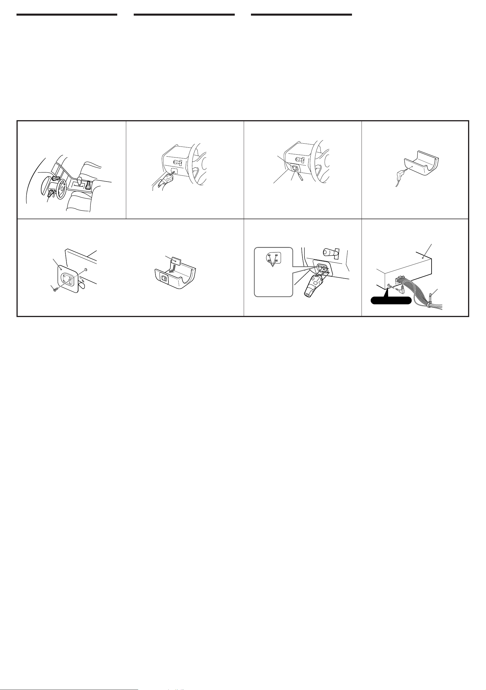
Installing the rotary
commander
Notes
• Choose the mounting location carefully so that
the rotary commander will not interfere with
operating the car.
• Do not install the rotary commander in a place
where it may jeopardise the safety of the
(front) passenger in anyway.
• When installing the rotary commander, be sure
not to damage the electrical cables, etc. on the
other side of the mounting surface.
• Avoid installing the rotary commander where it
may be subject to high temperatures, such as
from direct sunlight or hot air from the heater,
etc.
Instalación del mando
rotativo
Notas
• Elija cuidadosamente el lugar de montaje de
forma que el mando rotativo no dificulte la
conducción del coche.
• No instale el mando rotativo en un lugar donde
pueda poner en peligro la seguridad del
pasajero acompañante.
• Al instalar el mando rotativo, asegúrese de no
dañar los cables de electricidad, etc., del otro
lado de la superficie de montaje.
• Procure no instalar el mando rotativo en un
lugar expuesto a altas temperaturas, como a la
luz solar directa o al aire caliente de la
calefacción, etc.
ƒw‚¸– ´ ƒ¡––¤ „
ø
•
⁄p⁄ ¿ ƒw‚¸ƒ ‚m¡A¥O– ´ ƒ¡––¤ „⁄£§«ˆ“¤T¤fi r p
§@
¡C
•
⁄£¥i§ – ´ ƒ¡––¤ „‚¸ƒb¥ ƒ „ ¡]«e›–¡^›…«¨ƒ‡ƒM I
“”ƒa⁄Ł
¡C
•
ƒw‚¸– ´ ƒ¡––¤ „fi ¡A‰—“‘•N⁄£›n¯ `‡ • v¶¸⁄˛ƒw‚¸
›–⁄ˇ›–“”„q‰u ¥
•
` §K§ – ´ ƒ¡––¤ „ƒw‚¸ƒb “•¯¡Aƒp“‰fig¶§¥œ⁄U'˛‡Q
•xfi … ‹y§j¤ “”ƒa⁄Ł
¡C
¡C
Example of a mounting location
Ejemplo de un lugar de montaje
ƒw‚¸¤ ⁄l
4
B
A
12
B
Mark
Marca
O‚„
5
Heavy duty tape, etc.
Cinta adhesiva resistente, etc.
–j⁄O‰ƒ–a ¥
Holes
Orificios
⁄p⁄
3
6
REMOTE IN
Master unit
Unidad principal
¥D
C
1 Choose the exact location for the rotary
commander to be mounted, then clean
the mounting surface.
Dirt or oil impair the adhesive strength of
the double-sided adhesive tape.
2 Mark position for the supplied screw.
Use the screw hole on the mounting
hardware B to mark the position.
If you cannot make the mounting hardware
B fit easy; cut the mounting hardware B to
fit the steering wheel column cover.
3 Remove the steering wheel column cover,
and drill 2 mm diameter hole where you
have marked.
4 Warm the mounting surface and the
double-sided adhesive tape on the
mounting hardware B to the
temperature of 20°C to 30°C, and attach
the mounting hardware onto the
mounting surface by applying even
pressure. Then screw it down with the
supplied screw A.
Attach a piece of heavy duty tape, etc. on the
other side of the mounting surface to cover
the protruding tip of the screw so that they
will not interfere with the electrical cables,
etc. inside the steering wheel column.
5 After installing the steering wheel column
cover, attach the rotary commander to the
mounting hardware by aligning the four
holes on the bottom of the rotary
commander to the four catches on the
mounting hardware and sliding the rotary
commander until it locks into place as
illustrated.
Note
If you are mounting the rotary commander
to the steering wheel column, make sure that
the protruding tip of the screw on the inner
surface of the column do not in anyway
hinder or interfere with the movement of the
rotating shaft, operative parts of the switches
or the electrical cables, etc. inside the
column.
6 After connecting, bundle up the
connecting cord of the rotary remote with
other connecting cords of the audio
equipment by attaching the supplied
cramper C. Be sure to leave some slack in
the connecting cord between the plug
and the cramper as illustrated.
1 Una vez elegido el lugar de montaje del
mando rotativo, limpie previamente la
superficie de montaje.
La suciedad o la grasa dañan la intensidad
adhesiva de la cinta adhesiva de dos caras.
2 Marque la posición para el tornillo
suministrado.
Para ello, utilice el orificio para tornillo de la
ferretería de montaje B.
Si no es posible instalar con facilidad la pieza
B, córtela de forma que encaje en la cubierta
de la columna de la dirección.
3 Extraiga la cubierta de la columna de la
dirección y haga orificios de 2 mm. de
diámetro en los lugares marcados.
4 Caliente la superficie de montaje y la cinta
adhesiva de doble cara de la ferretería de
montaje B a una temperatura entre 20°C
y 30°C, y ajuste la ferretería de montaje a
la superficie de montaje ejerciendo una
presión uniforme. A continuación, apriete
el tornillo A suministrado.
Adhiera un trozo de cinta adhesiva
resistente, etc., en el otro lado de la
superficie de montaje para cubrir el extremo
sobresaliente del tornillo, de forma que no
interfiera con los cables eléctricos, etc., del
interior de la columna de dirección.
5 Una vez instalada la cubierta de la
columna de dirección, fije el mando
rotativo a la ferretería de montaje
alineando los cuatro orificios de la parte
inferior del mando con los cuatro
enganches de la ferretería de montaje. A
continuación, deslice el mando hasta que
encaje en su sitio como se muestra en la
ilustración.
Nota
Si monta el mando rotativo en la columna de
dirección, asegúrese de que el extremo
sobresaliente del tornillo de la superficie
interior de la columna no dificulte de
ninguna forma el movimiento del eje de
rotación, componentes operativos de los
conmutadores o los cables eléctricos, etc., del
interior de la columna.
6 Una vez realizada la conexión, recoja el
cable de conexión del mando con el resto
de los cables de conexión del equipo de
audio mediante el fijador de cables C
suministrado. Como muestra la
ilustración, procure dejar un espacio en el
cable de conexión entre el enchufe y el
fijador de cables.
1 ¿ ⁄@› AƒXƒw‚¸– ´ ƒ¡––¤ „“”ƒa⁄Ł¡A M«Æ
†M… ƒw‚¸›–¡C
“ ›–»Œ¯…'˛ƒ‡“oƒˆ•|· §C¤ ›–‰ƒ–a“”´H¶K⁄O¡C
2 ¥· 1 › “ –a`‡ vƒ ‚m“”…—»x¡C
§Q¥˛ƒw‚¸⁄›“ B ⁄W“”`‡ v⁄ ¥·`‡ vƒ ‚m…—»x¡C
ƒp“G⁄›“ B ⁄£fie' fiMƒX¡A¥i«d⁄`⁄@⁄U⁄›“ B
¤ˇfiMƒX´ ƒV‰L‹W¥~· ¡C
3 ¤œ⁄U´ ƒV‰L‹W¥~· ¡A¤ˆƒb' §@…—»x⁄W˘p‡q 2 mm
“‰fi|“” v⁄ ¡C
4 § ƒw‚¸›–⁄˛ƒw‚¸⁄›“ B “”¤ ›–‰ƒ–a¥[… ƒ 20¢X
¤ 30¢X {« ¡A M«Æ§ ƒw‚¸⁄›“ ¶Kƒb´ ƒV‰L‹W¥~
· ¡A¶Kfi ' ‹I¥[ £⁄O¶•§¡ ¥¡C M«Æ¥˛“ ˜ “”`‡ v
A 'T'w⁄§¡C
ƒbƒw‚¸›–“”⁄ˇ›–⁄§`‡ • vƒy” ‡¡⁄ ¡A¶K–i–j⁄O
‰ƒ–a ¥¡A¥H§K•l¶¸´ ƒV‰L‹W‚ ›–“”„q‰u ¥¡C
5 ƒb´ ƒV‹W¥~· ›«•s‚¸⁄W¥H«Æ¡A§ – ´ ƒ¡––¤ „
‚¸ƒbƒw‚¸⁄›“ ⁄W¡C‚¸fi ‰—§ – ´ ƒ¡––¤ „'‡‡¡
“” 4 › ⁄p⁄ „ •˙ƒw‚¸⁄›“ ⁄W“” 4 › ⁄p„_¡A M«Æ
« • ·¡„ˇ' ¥ ¡A§ – ´ ƒ¡––¤ „·¡⁄J⁄›“ ƒ ƒw
‚¸'wƒ ¡C
ø
ƒb§ – ´ ƒ¡––¤ „‚¸ƒb´ ƒV‰L‹W¥~· fi ¡A¥†¶•“‘•N
´ ƒV‹W‚ “”`‡ • v⁄§ƒy” ¡A⁄£¥i“ ˆ“'˛…v¯T¤ ´ ƒV
‹W· ‚ ›–“”´ ¶b¡B¶}ˆ “” §@‡¡⁄ '˛„q‰u ¥
¡C
6 ‡s– §„†ƒ«Æ¡A‰—‚¸¥H“ –a“”§¤ƒ' C §–´ƒ¡
––¤ „“”‡s– ‰u'M`n W‡]‡˘“”¤ ¥L‡s– ‰u
fi„⁄ª⁄@ _¡Cƒp„ˇ' ¥ ¡A‰—“‘•Nƒb·¡ Y'M§¤ƒ'⁄§
¶¡“”‡s– ‰u¡A⁄@'w›nfld⁄@¤˙ˆPƒ¢¡C
 Loading...