

SONY MDX-C8900R Service Manual
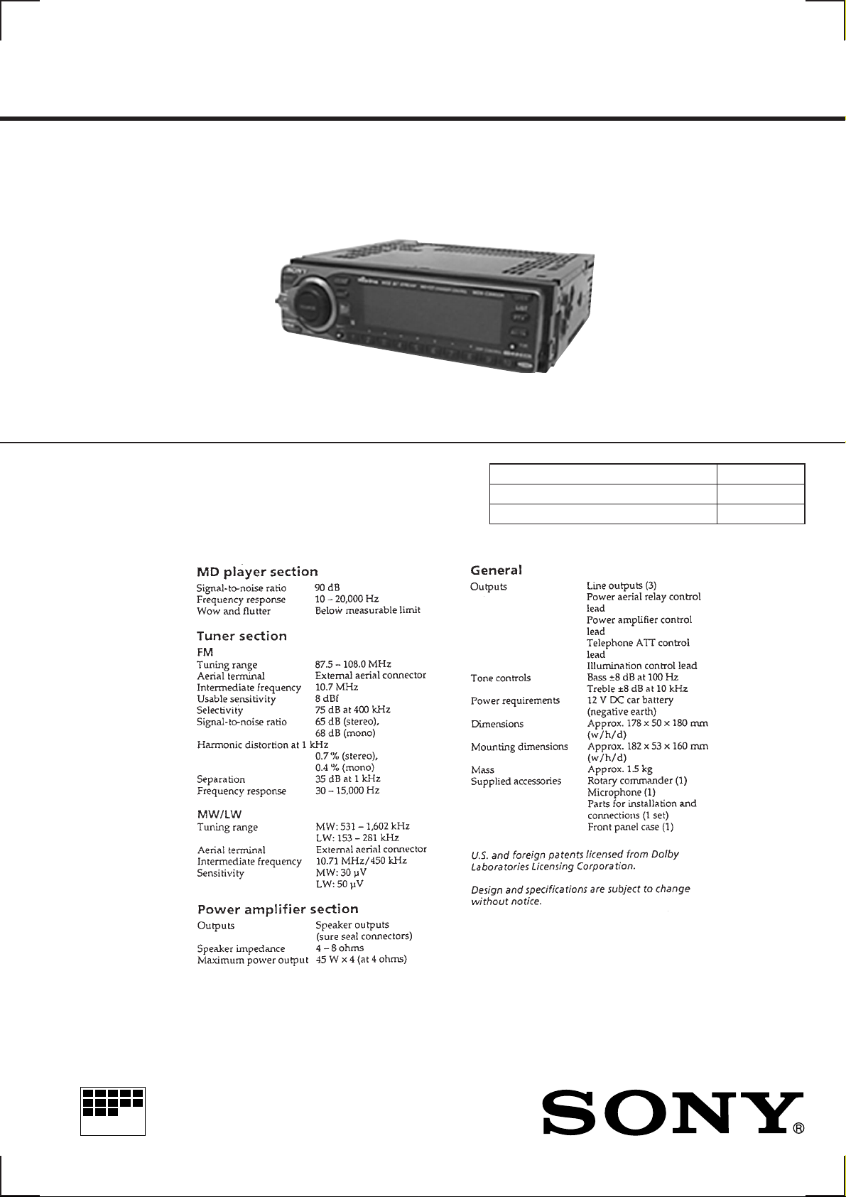
MDX-C8900R
SERVICE MANUAL
SPECIFICATIONS
AEP Model
UK Model
Model Name Using Similar Mechanism MDX-C7900R
Base Mechanism Type MG-164KE-138
Optical Pick-Up Name KMS-241B/J2N
MICROFILM
FM/MW/LW MINIDISC PLAYER
NOTES ON HANDLING THE OPTICAL PICK-UP
BLOCK OR BASE UNIT
The laser diode in the optical pick-up block may suffer electrostatic break-down because of the potential difference generated
by the charged electrostatic load, etc. on clothing and the human
body.
During repair, pay attention to electrostatic break-down and also
use the procedure in the printed matter which is included in the
repair parts.
The flexible board is easily damaged and should be handled with
care.
Notes on chip component replacement
• Never reuse a disconnected chip component.
• Notice that the minus side of a tantalum capacitor may be damaged by heat.
Flexible Circuit Board Repairing
• Keep the temperature of the soldering iron around 270 ˚C during repairing.
• Do not touch the soldering iron on the same conductor of the
circuit board (within 3 times).
• Be careful not to apply force on the conductor when soldering
or unsoldering.
NOTES ON LASER DIODE EMISSION CHECK
Never look into the laser diode emission from right avove when
checking it for adustment. It is feared that you will lose your sight.
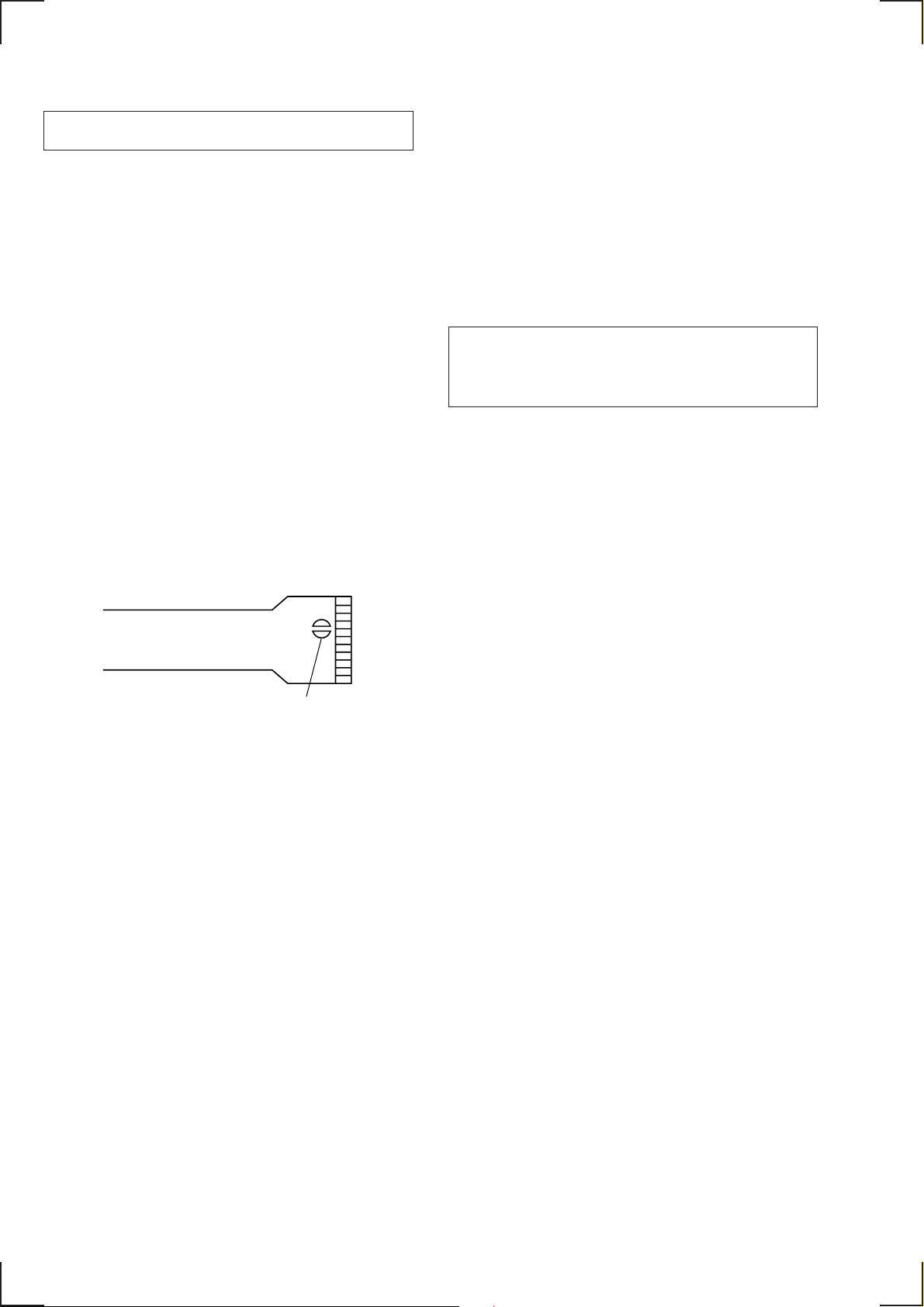
NOTES ON HANDLING THE OPTICAL PICK-UP BLOCK
(KMS-241B/J2N).
The laser diode in the optical pick-up block may suffer electrostatic break-down easily. When handling it, perform soldering
bridge to the laser-tap on the flexible board. Also perform m easures
against electrostatic break-down suff iciently before the operation.
The flexible board is easily damaged and should be handled with
care.
laser-tap
OPTICAL PICK-UP FLEXIBLE BOARD
CAUTION
Use of controls or adjustments or performance of procedures
other than those specified herein may result in hazardous radiation exposure.
SAFETY-RELATED COMPONENT WARNING!!
COMPONENTS IDENTIFIED BY MARK ! OR DOTTED
LINE WITH MARK ! ON THE SCHEMATIC DIAGRAMS
AND IN THE PARTS LIST ARE CRITICAL TO SAFE
OPERATION. REPLACE THESE COMPONENTS WITH
SONY PARTS WHOSE PART NUMBERS APPEAR AS
SHOWN IN THIS MANUAL OR IN SUPPLEMENTS PUBLISHED BY SONY.
– 2 –

TABLE OF CONTENTS
1. GENERAL
Location of Controls ....................................................... 4
Resetting the Unit ........................................................... 5
Detaching the Front Panel............................................... 5
Preparing the Rotary Commander .................................. 5
Setting the Clock............................................................. 5
Listening to an MD ......................................................... 5
Playing an MD in Various Modes ................................... 6
Creating a Programme .................................................... 6
Memorising Stations Automatically............................... 6
Memorising Only the Desired Stations .......................... 7
Receiving the Memorised Stations ................................. 7
Overview of the RDS Function ...................................... 7
Displaying the Station Name .......................................... 7
Re-Tuning the same Programme Automa tically ............ 7
Listening to Traffic Announcements .............................. 7
Presetting the RDS Stations with
the AF and TA Da ta ......................................................... 8
Recording the Traffic Announcements ........................... 8
Locating a Station by Programme Type ......................... 8
Setting the Clock Automatically..................................... 8
Selecting a “V Drive” Box for Registration................... 8
Registering a Vocal Phrase.............................................. 9
Requesting a Registered Source ..................................... 9
Recording a Voice Memo................................................ 9
Playing Back the Voice Memo........................................ 9
Erasing the Voice Memo ................................................. 9
Using the Rotary commander ......................................... 9
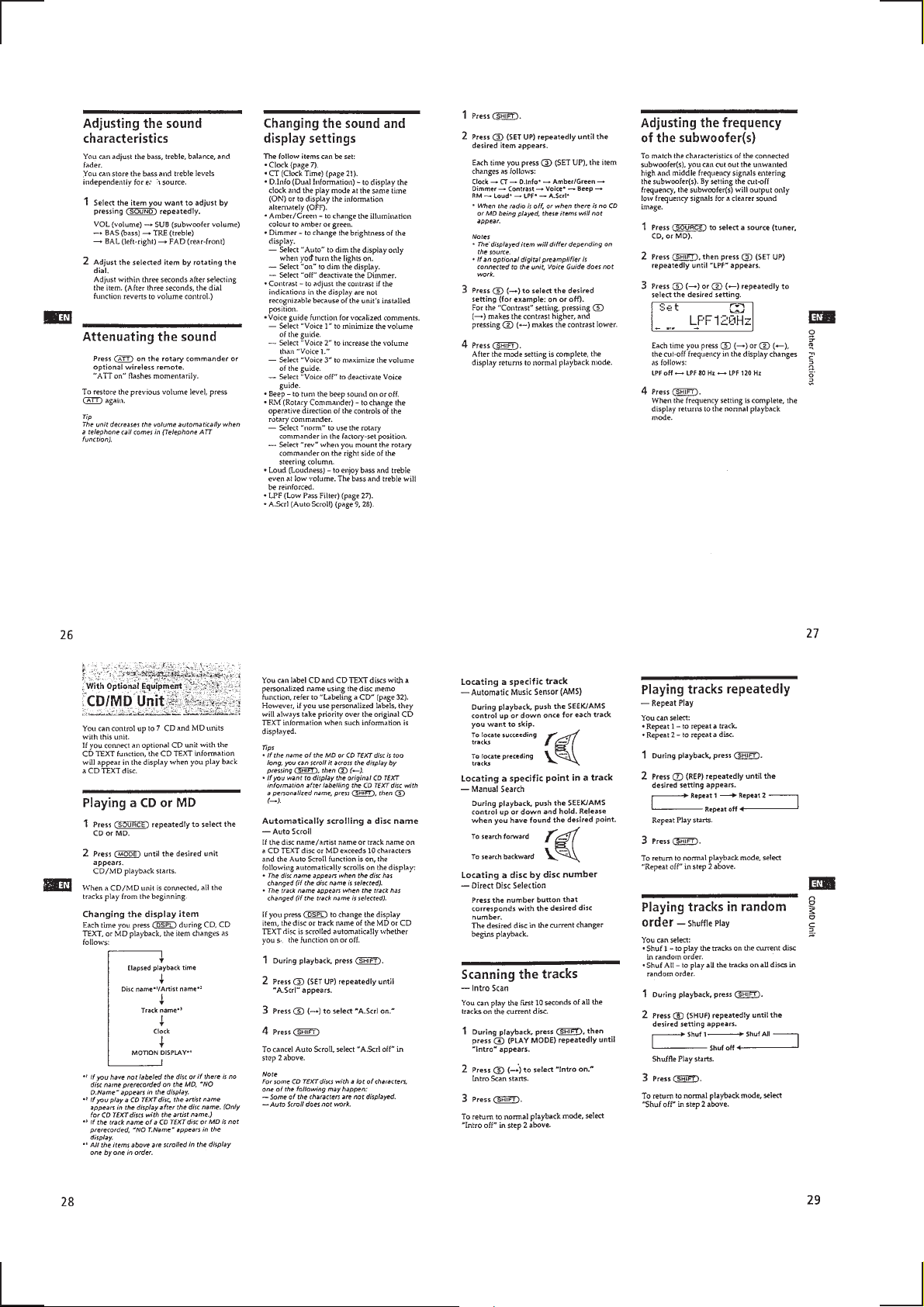
Adjusting the Sound Characteristics .............................. 10
Attenuating the Sound .................................................... 10
Changing the Sound and Display Settings ..................... 10
Adjusting the Frequency of the Subwoofer (s) .............. 10
Playing a CD or MD ....................................................... 10
Scanning the Tracks ........................................................ 10
Playing Tracks Repeatedly ............................................. 10
Playing Tracks in Random Order ................................... 10
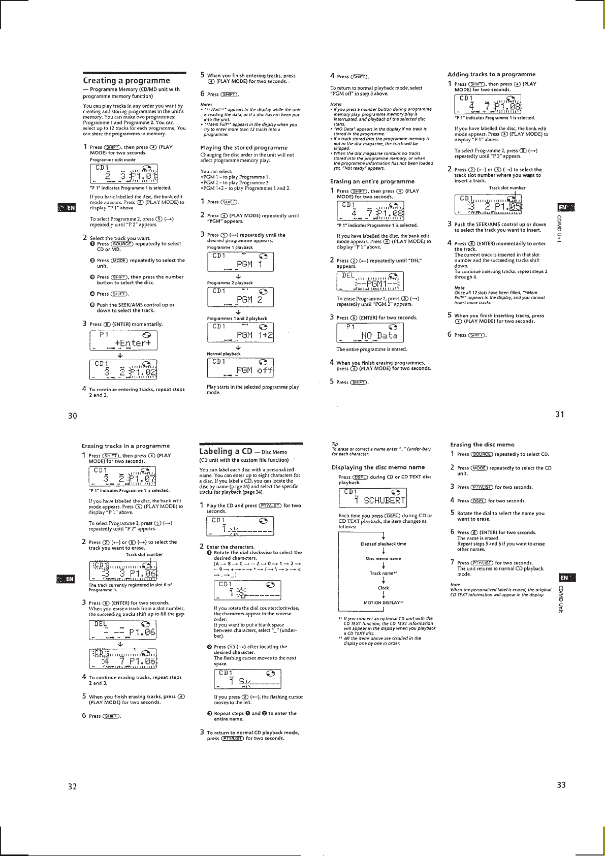
Creating a Programme .................................................... 11
Labeling a CD ................................................................. 11
Locating a Disc by Name................................................ 12
Selecting Specific Tracks for Playback .......................... 12
Selecting a Surround Menu ............................................ 12
Storing a Surround Effect onto CDs............................... 12
Selecting the Listening Position ..................................... 12
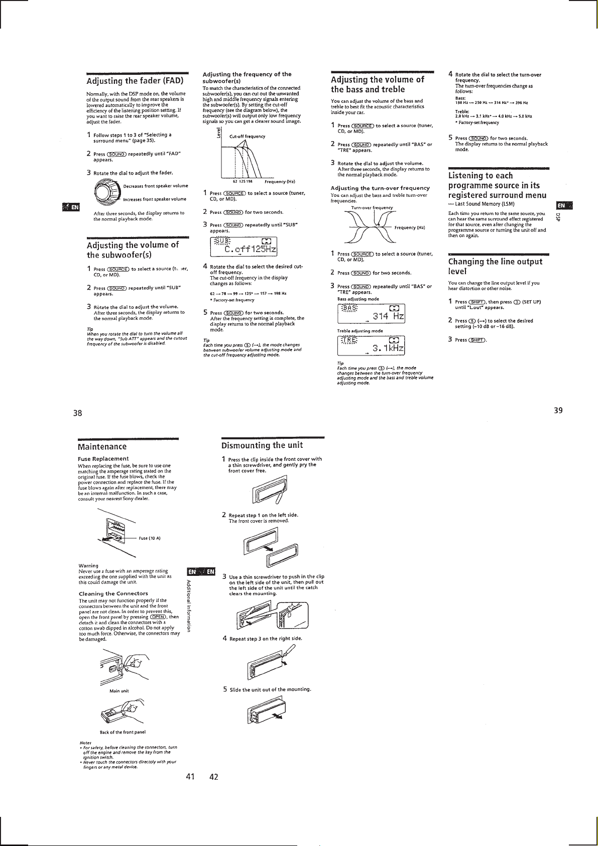
Adjusting the Fader (FAD) ............................................. 13
Adjusting the Volume of the Subwoofer (s) ................... 13
Adjusting the Volume of the Bass and Treble ................ 13
Listening to Each Programme Source in Its Registered
Surround Menu ............................................................... 13
Changing the Line Output Level .................................... 13
Maintenance .................................................................... 13
Dismounting the Unit...................................................... 13
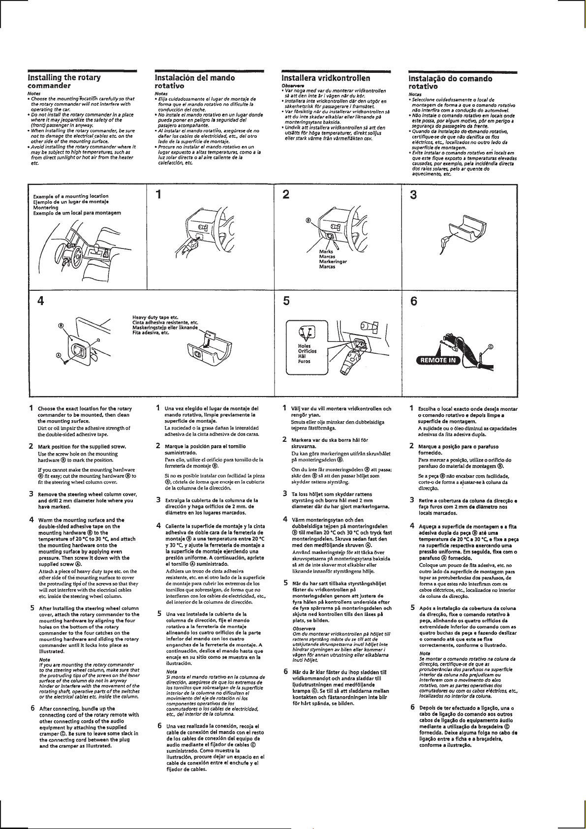
Installation....................................................................... 14
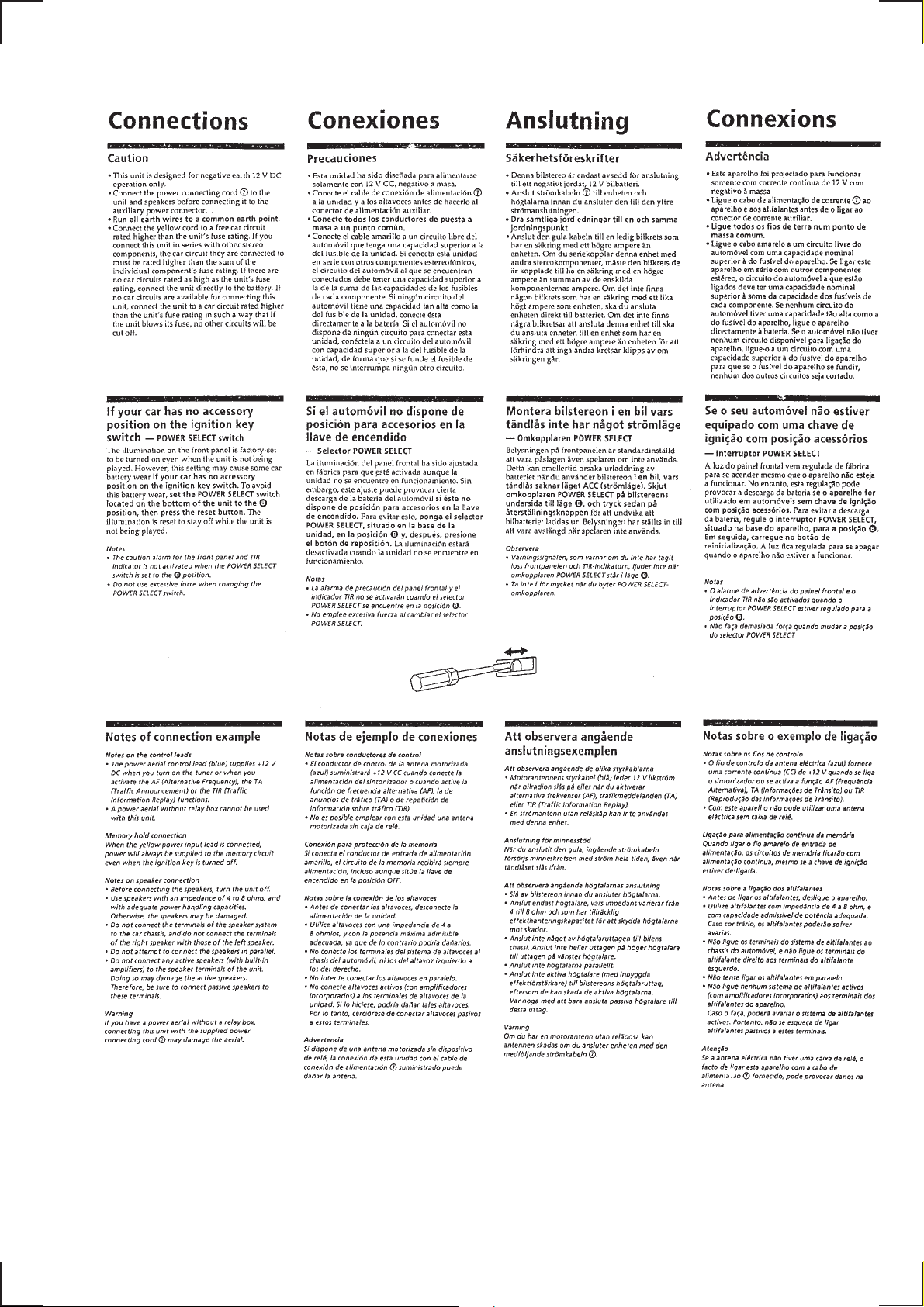
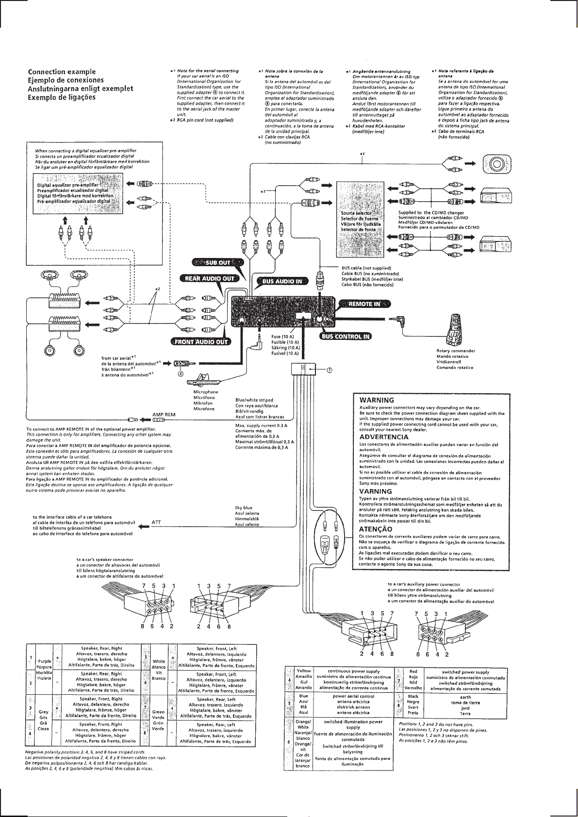
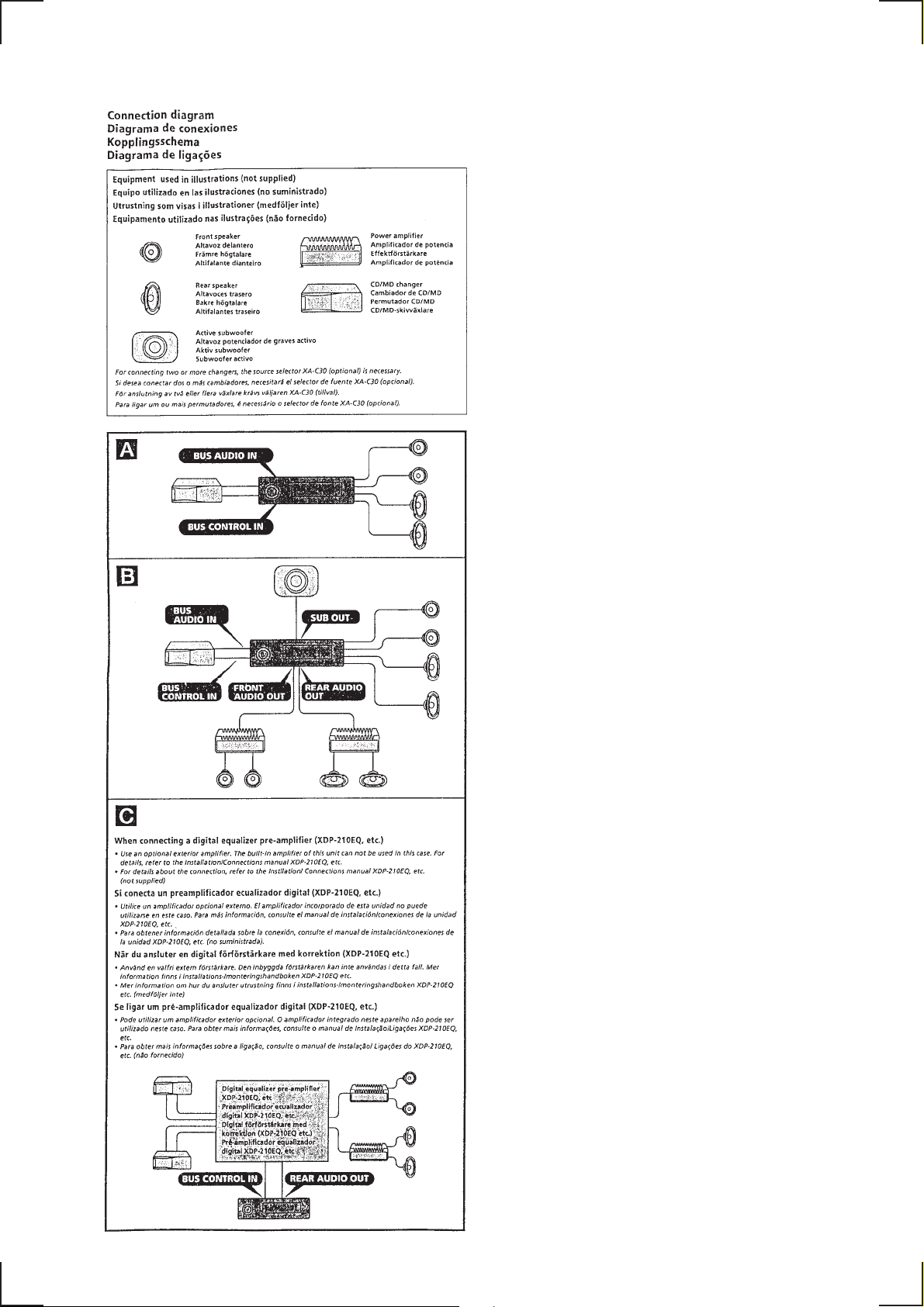
Connections..................................................................... 17
3. ELECTRICAL ADJUSTMENTS
Test Mode........................................................................ 25
MD Section ..................................................................... 25
Tuner Section .................................................................. 25
4. DIAGRAMS
4-1. Block Diagram – SERVO Section – ............................... 29
4-2. Block Diagram – TUNER Section – .............................. 31
4-3. Block Diagram – MAIN Section – ................................. 33
4-4. Block Diagram
– DISPLAY/KEY CONTROL Section –........................ 35
4-5. Block Diagram – BUS CONTROL/
POWER SUPPLY Section – ........................................... 37
4-6. Notes for Printed Wiring Boards and
Schematic Diagrams ....................................................... 40
4-7. Printed Wiring Boards – SERVO Section – ................... 41
4-8. Schematic Diagram – SERVO Section (1/3) – ............... 43
4-9. Schematic Diagram – SERVO Section (2/3) – ............... 45
4-10. Schematic Diagram – SERVO Section (3/3) – ............... 47
4-11. Printed Wiring Board
– MAIN Board (Component Side) – .............................. 49
4-12. Printed Wiring Boards
– MAIN Board (Conductor Side)/
SUPER CAPACITOR Board –.................................... 51
4-13. Schematic Diagram – MAIN Section (1/4) – ................. 53
4-14. Schematic Diagram – MAIN Section (2/4) – ................. 55
4-15. Schematic Diagram – MAIN Section (3/4) – ................. 57
4-16. Schematic Diagram – MAIN Section (4/4) – ................. 59
4-17. Printed Wiring Board – AUDIO Section – ..................... 61
4-18. Schematic Diagram – AUDIO Section –........................ 63
4-19. Printed Wiring Board – PANEL Section – ..................... 65
4-20. Schematic Diagram – PANEL Section –........................ 67
4-21. Printed Wiring Board – RELAY Section –..................... 69
4-22. Schematic Diagram – RELAY Section – ....................... 71
4-23. IC Pin Function Description ........................................... 81
5. EXPLODED VIEWS ................................................ 91
6. ELECTRICAL PARTS LIST ............................... 95
2. DISASSEMBLY ......................................................... 20
– 3 –

SECTION 1
GENERAL
This section is extracted from
instruction manual.
– 4 –

– 5 –

– 6 –

– 7 –
– 8 –
– 9 –
– 10 –
– 11 –

– 12 –
– 13 –

– 14 –

– 15 –
– 16 –
– 17 –
– 18 –
– 19 –
SECTION 2
DISASSEMBLY
Note: Follow the disassembly procedure in the numerical order given.
SUB PANEL ASS’Y
2
two claws
4
sub panel ass’y
1
three screws
(PTT2.6 × 6)
2
claw
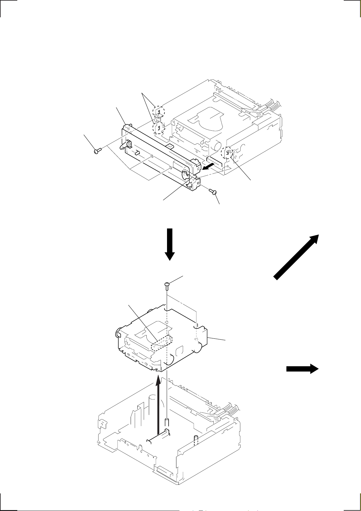
MECHANISM DECK (MG-164KE-138)
2
connector
(CN101)
3
connector
(CN701)
1
two screws
(PTT2.6
×
4)
1
screw
(PTT2.6 × 6)
3
mechanism deck
(MG-164KE-138)
– 20 –
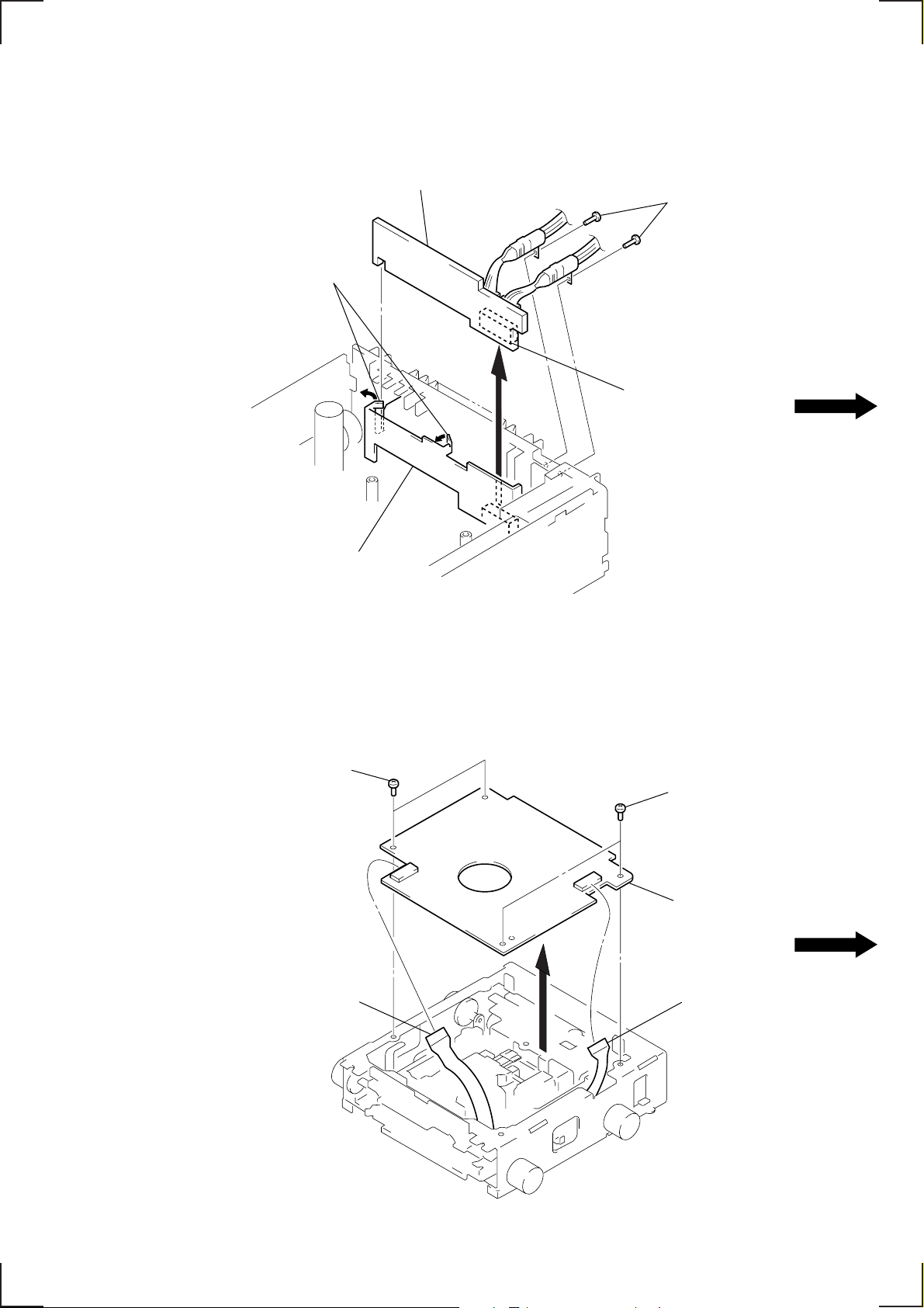
AUDIO BOARD
)
2
Bend two claws of
bracket (AUDIO) in
the direction of arrows.
bracket (AUDIO)
4
AUDIO board
3
connector
(CN803)
1
two screws
(PTT2.6
×
10
SERVO BOARD
3
two screws
(BVTT2
1
sensor flexible board
(CN102)
×
4)
3
two screws
(BVTT2
×
4)
4
servo board
2
flexible board
(CN103)
– 21 –
)
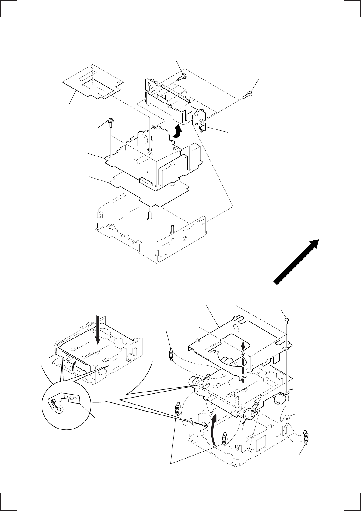
MAIN BOARD
3
2
three ground point screws
4
5
shield plate (2)
MAIN board
insulating sheet
6
six screws
(PTT2.6
×
10)
1
two screws
(PTT2.6
7
Remove the heat sink in
the direction of the arrow.
×
10)
FLOAT BLOCK
float block
Release of the lock.
Pushing an arrow A part, raise
5
the float block up ward at the
front to release a lock.
A
lever (lock R)
lever (lock L)
3
spring (FL2)
2
MD cover ass’y
1
four screws
(BVTT2
×
4)
4
two springs (FL)
– 22 –
3
spring (FL2
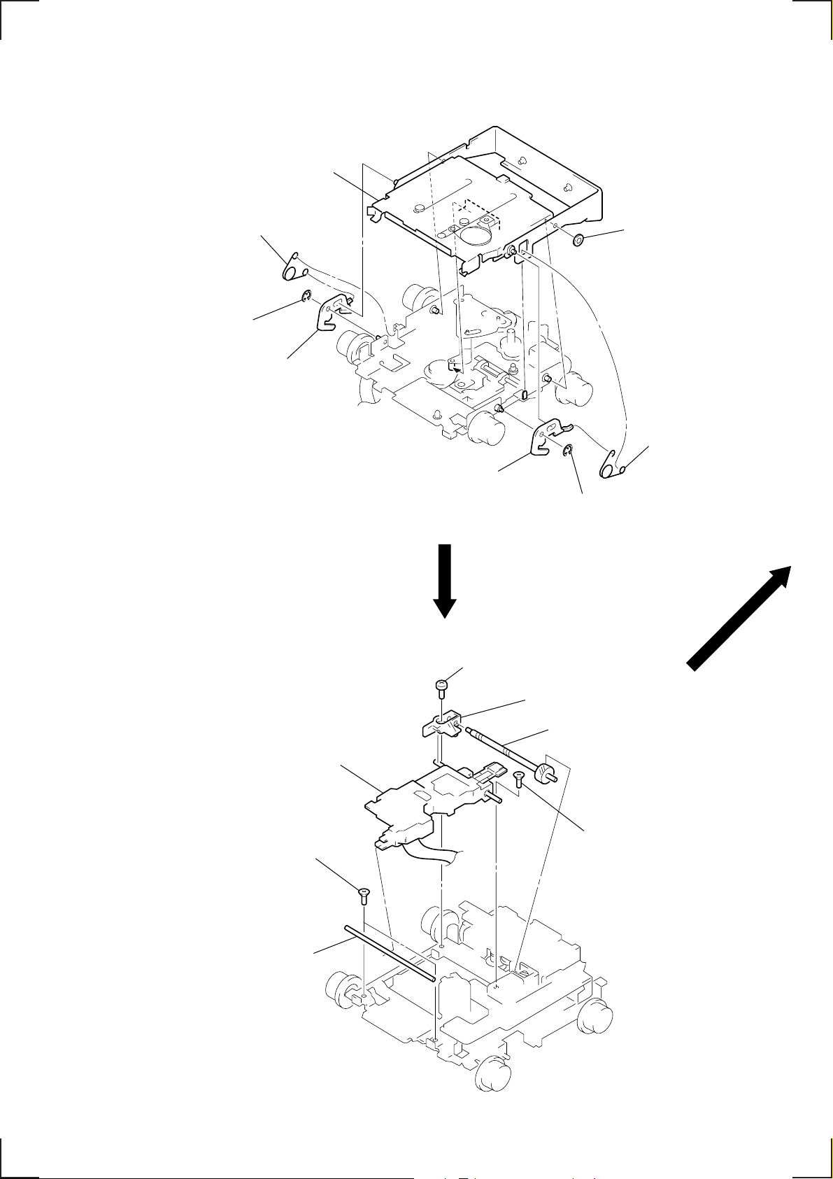
HOLDER ASS’Y
)
y
1
spring (CHKG)
2
stop ring E (1.5)
3
lever (lock R)
5
holder ass’y
3
lever (lock L)
2
stop ring E (1.5)
4
washer (M)
1
spring (CHKG
OPTICAL PICK-UP (KMS-241B/J2N)
7
optical pick-up
(KMS-241B/J2N)
1
two screws
(K2 × 3)
2
shaft (SL2)
4
screw
(B2 × 3)
6
bearing (SL)
5
feed screw ass’
3
screw
(K2 × 3)
– 23 –
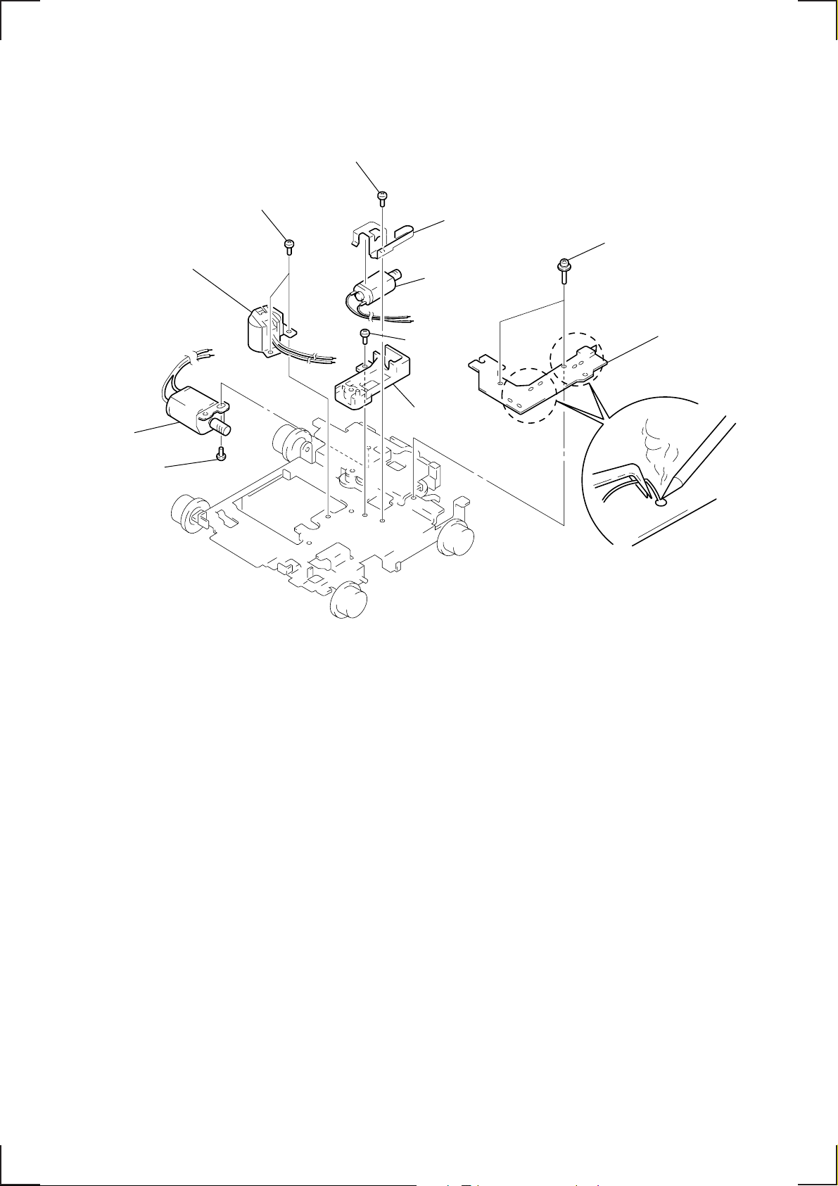
MOTOR ASS’Y (M901, M902, M903), SENSOR BOARD
d
4
screw
(P1.7
×
1.8)
9
two screws
(P1.7
×
1.8)
0
spindle motor
ass’y (M901)
!™
loading motor
ass’y (M903)
!¡
screw
(P2
×
2.2)
7
8
6
screw
(B2
base (SL)
5
bracket (SL)
sled motor ass’y
(M902)
×
3)
2
two screws
(2
×
8)
3
sensor boar
1
Remove solders of motors
(M901, M902, M903).
– 24 –
SECTION 3
)
SHUF
REG
SHUF
REG
ELECTRICAL ADJUSTMENTS
TEST MODE
This set have the test mode function. In the test mode, FM Auto
Scan/Stop Level and MW Auto Scan/Stop Level adjustments can
be performed easier than it in ordinary procedure.
<Set the Test Mode>
1. Set the “power select” switch (SW500) is “A (ON)” position.
2. Turn ON the regulated power supply. (All LEDs on the set
lights up, and the clock is displayed.)
Note: Press the [OFF] button, if the clock is not displayed.
3. Push the preset [4] button.
4. Push the preset [5] button.
5. Press the preset [1] button for more than two seconds.
6. Then the display indicates all lights, the test mode is set.
<Release the Test mode>
1. Push the [OFF] button.
2. Return the “power select” switch (SW500) to initially set position.
See the adjustment location from on page 28 for the adjustment.
MD SECTION
MD section adjustments are done automatically in this set.
TUNER SECTION
0 dB=1µV
Cautions during repair
When the tuner unit is defective, replace it by a new one because its internal block is difficult to repair.
Note: Adjust the tuner section in the sequence shown below.
1. FM Auto Scan/Stop Level Adjustment
2. FM Stereo Separation Adjustment (Wide)
3. FM Stereo Separation Adjustment (Narrow)
4. FM RDS S-Meter Adjustment
5. MW Auto Scan/Stop Level Adjustment
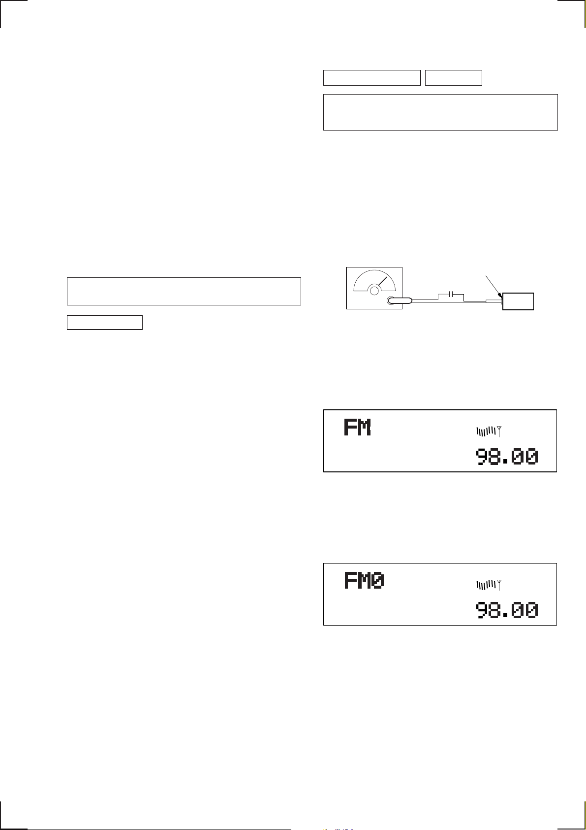
FM Auto Scan/Stop Level Adjustment
Setting:
[SOURCE] button : FM
FM RF signal
generator
Carrier frequency : 98.00 MHz
Output level : 22 dB (12.6
Mode : mono
Modulation : 1 kHz, 22.5 kHz deviation (30%
Procedure:
1. Set to the test mode.
2. Push the
[SOURCE] button and set to FM.
antenna jack (CN1)
0.01 µF
µ
V)
set
Display
3. Adjust the volume RV2 on TU1 by turning clockwise untill
“0” is shown next to “FM” on the display window, If “0” is
already shown or the volume RV2 has been turned too far,
turn it back counterclockwise untill “0” is disappeared once,
then try this adjustment.
Display
Adjustment Location: See page 28.
– 25 –
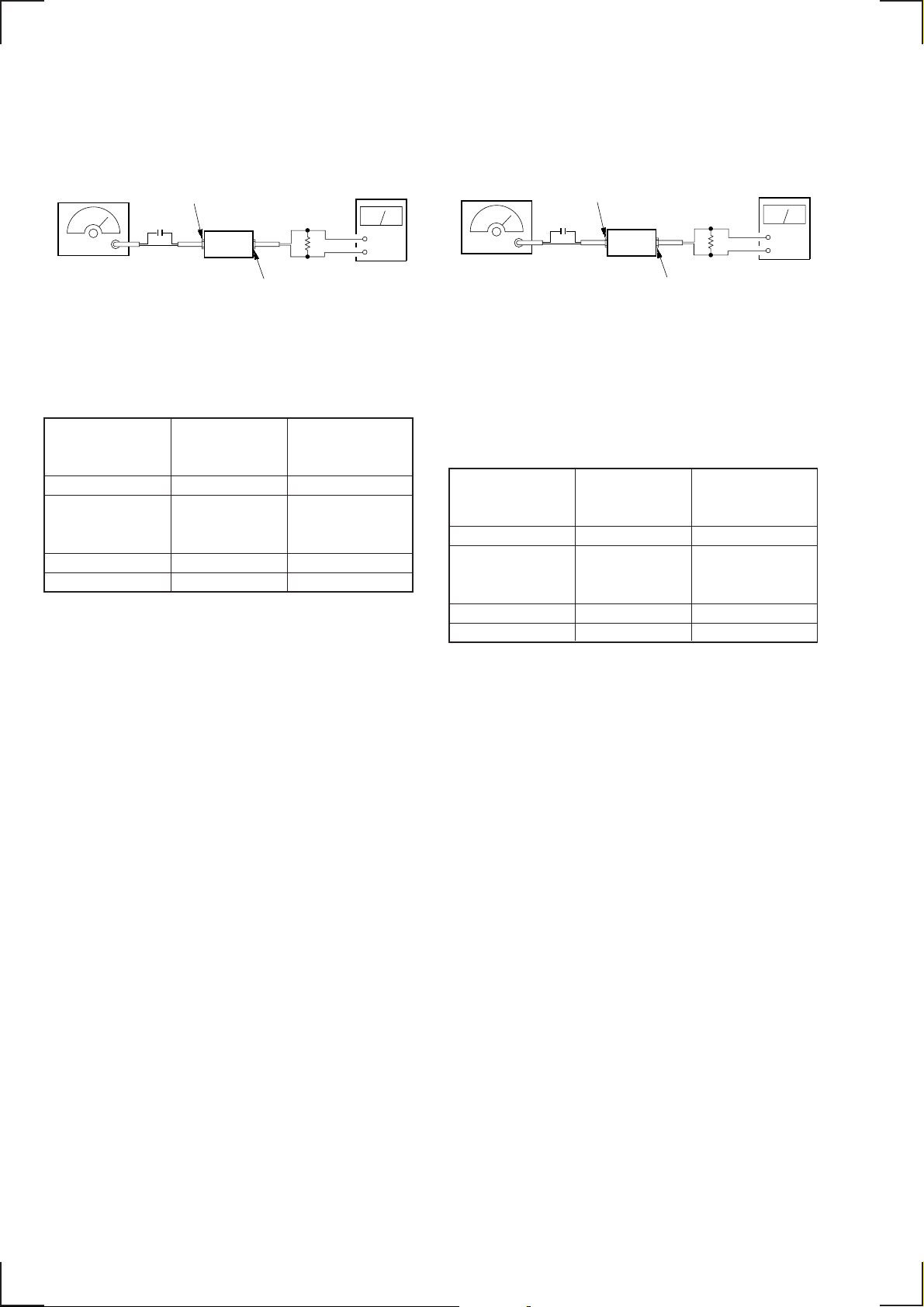
FM Stereo Separation Adjustment (Wide)
Setting:
[SOURCE] button : FM
FM Stereo Separation Adjustment (Narrow)
Setting:
[SOURCE] button : FM
FM RF signal
generator
Carrier frequency : 98.00 MHz
Output level : 70 dB (3.2 mV)
Mode : stereo
Modulation : main: 1 kHz, 33.75 kHz deviation (45%)
antenna jack (CN1)
0.01 µF
Ω)
(75
sub : 1 kHz, 33.75 kHz deviation (45%)
: 19 kHz pilot: 7.5 kHz deviation (10%)
set
10 k
REAR
AUDIO OUT
Ω
level meter
+
–
Procedure:
1. Adjust the volume RV3 on FM/AM tuner unit (TU1) for the
best separation.
FM Stereo
signal generator
output channel
L-CH L-CH A
L-CH R-CH Adjust RV3 on TU1
R-CH R-CH C
R-CH L-CH D
Level meter Level meter
connection reading (dB)
B
for minimum reading.
L-CH Stereo separation: A-B
R-CH Stereo separation: C-D
The separations of both channels should be equal.
Specification: Separation more than 24 dB
Adjustment Location: See page 28.
FM RF signal
generator
Carrier frequency : 98.00MHz
Output level : 70 dB (3.2 mV)
Mode : stereo
Modulation : main: 1 kHz, 20 kHz deviation (26.5%)
antenna jack (CN1)
0.01 µF
Ω)
(75
sub : 1 kHz, 20 kHz deviation (26.5%)
: 19 kHz pilot: 7.5 kHz deviation (10%)
set
10 k
REAR
AUDIO OUT
Ω
level meter
+
–
Procedure:
1. Push the
[SHIFT] button.
2. Push the [4] button four times.
3. Push the [5] button twice and set to narrow mode.
4. Adjust the volume RV4 on FM/AM tuner unit (TU1) for the
best separation.
FM Stereo
signal generator
output channel
L-CH L-CH A
L-CH R-CH Adjust RV4 on TU1
R-CH R-CH C
R-CH L-CH D
Level meter Level meter
connection reading (dB)
B
for minimum reading.
L-CH Stereo separation: A-B
R-CH Stereo separation: C-D
The separations of both channels should be equal.
Specification: Separation more than 18 dB
Adjustment Location: See page 28.
– 26 –
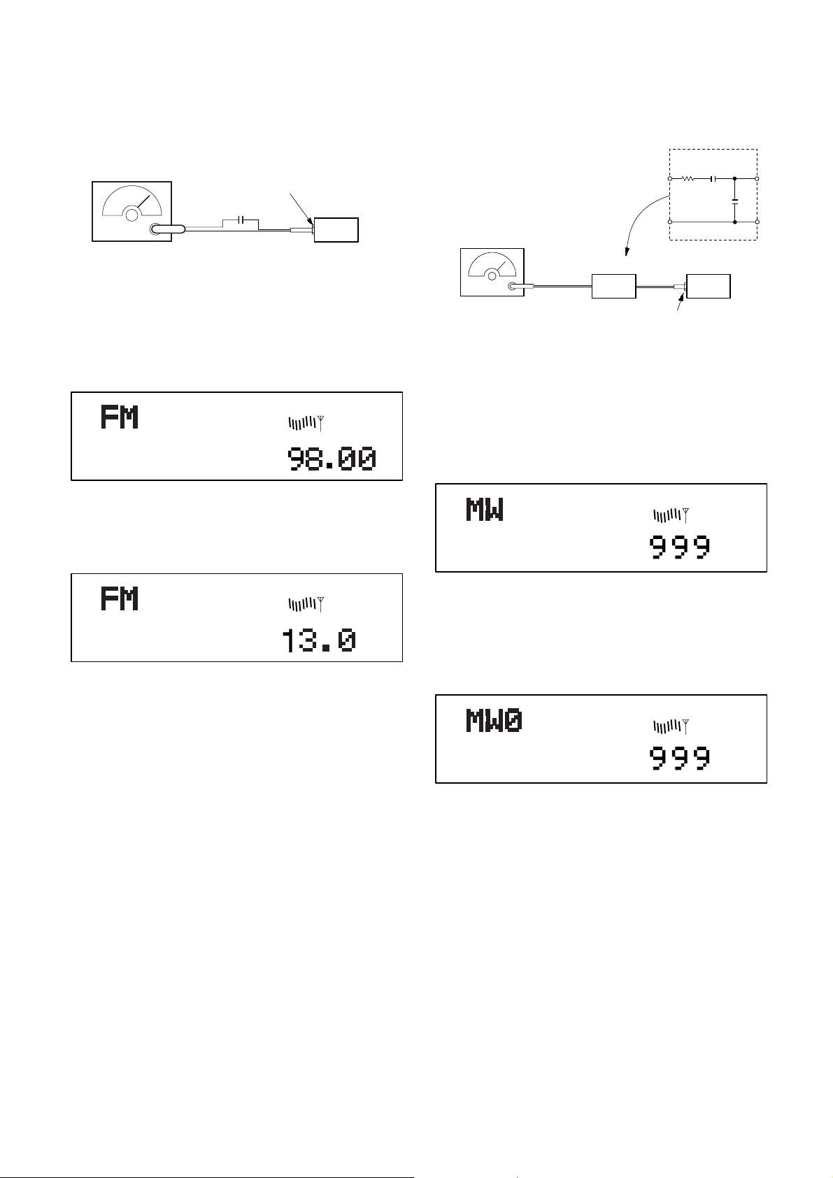
FM RDS S-Meter Adjustment
(
)
Setting:
[SOURCE] button : FM
MW Auto Scan/Stop Level Adjustment
Setting:
[SOURCE] n [MODE] button : MW
FM RF signal
generator
Carrier frequency : 98.00 MHz
Output level : 35 dB (56.2
Mode : mono
Modulation : no modulation
antenna jack (CN1)
0.01
µ
F
µ
V)
set
Procedure:
1. Set to the test mode. (See page 25.)
2. Push the
[SOURCE] button and set to FM.
Display
SHUF
REG
3. Push the preset
[10] button .
4. Adjust RV1 on MAIN board so that the display indication is
“13.0”.
Display
AM RF signal
generator
AM dummy antenna
(50 Ω)
Carrier frequency : 999 kHz
30% amplitude
modulation by
1 kHz signal
Output level : 33 dB
44.7 µV
Procedure:
1. Set to the test mode. (See page 25.)
2. Push the
3. Push the
[SOURCE] button and set to FM.
[MODE] button and set to MW.
Display
SHUF
TP
30
Ω
15 pF
65 pF
set
antenna jack (CN1)
SHUF
REG
Specification: Display indication: 12.8 to 13.2.
Adjustment Location: See page 28.
4. Adjust the volume RV1 on TU1 by turning clockwise untill
“0” is shown next to “MW” on the display window, If “0” is
already shown or the volume RV1 has been turned too far,
turn it back counterclockwise untill “0” is disappeared once,
then try this adjustment.
Display
SHUF
TP
Adjustment Location: See page 28.
– 27 –
 Loading...