

Sony MDX-C7970/C7970R Service Manual

MICROFILM
SERVICE MANUAL
Model Name Using Similar Mechanism MDX-C7900/C7900R
Base Mechanism Type MG-164N-138
Optical Pick-Up Name KMS-241B/J1NP
US Model
Canadian Model
E Model
MDX-C7970
AEP Model
UK Model
MDX-C7970R
SPECIFICATIONS
MDX-C7970/C7970R
Photo: MDX-C7970R
FM/AM(MW/LW) MINIDISC PLAYER
– Continued on next page –
For RM-X4S (Remote Commander),
please refer to RM-X4S Service Manual
(9-925-698-∏) previously issued.
– 2 –
Notes on chip component replacement
• Never reuse a disconnected chip component.
• Notice that the minus side of a tantalum capacitor may be damaged by heat.
Flexible Circuit Board Repairing
• Keep the temperature of the soldering iron around 270 ˚C during repairing.
• Do not touch the soldering iron on the same conductor of the
circuit board (within 3 times).
• Be careful not to apply force on the conductor when soldering
or unsoldering.
NOTES ON HANDLING THE OPTICAL PICK-UP
BLOCK OR BASE UNIT
SAFETY-RELATED COMPONENT WARNING!!
COMPONENTS IDENTIFIED BY MARK ! OR DOTTED
LINE WITH MARK ! ON THE SCHEMATIC DIAGRAMS
AND IN THE PARTS LIST ARE CRITICAL TO SAFE
OPERATION. REPLACE THESE COMPONENTS WITH
SONY PARTS WHOSE PART NUMBERS APPEAR AS
SHOWN IN THIS MANUAL OR IN SUPPLEMENTS PUBLISHED BY SONY.
CAUTION
Use of controls or adjustments or performance of procedures
other than those specified herein may result in hazardous radiation exposure.
The laser diode in the optical pick-up block may suffer electrostatic break-down because of the potential difference generated
by the charged electrostatic load, etc. on clothing and the human
body.
During repair, pay attention to electrostatic break-down and also
use the procedure in the printed matter which is included in the
repair parts.
The flexible board is easily damaged and should be handled with
care.
NOTES ON LASER DIODE EMISSION CHECK
Never look into the laser diode emission from right avove when
checking it for adustment. It is feared that you will lose your sight.
NOTES ON HANDLING THE OPTICAL PICK-UP BLOCK
(KMS-241B/J1NP)
The laser diode in the optical pick-up block may suffer electrostatic break-down easily. When handling it, perform soldering
bridge to the laser-tap on the flexible board. Also perform m easures
against electrostatic break-down suff iciently before the operation.
The flexible board is easily damaged and should be handled with
care.
laser-tap
OPTICAL PICK-UP FLEXIBLE BOARD
ATTENTION AU COMPOSANT AYANT RAPPORT
À LA SÉCURITÉ!
LES COMPOSANTS IDENTIFIÉS P AR UNE MARQUE !
SUR LES DIAGRAMMES SCHÉMATIQUES ET LA LISTE
DES PIÈCES SONT CRITIQUES POUR LA SÉCURITÉ
DE FONCTIONNEMENT. NE REMPLACER CES COMPOSANTS QUE PAR DES PIÈCES SONY DONT LES
NUMÉROS SONT DONNÉS DANS CE MANUEL OU
DANS LES SUPPLÉMENTS PUBLIÉS PAR SONY.

– 3 –
1. GENERAL
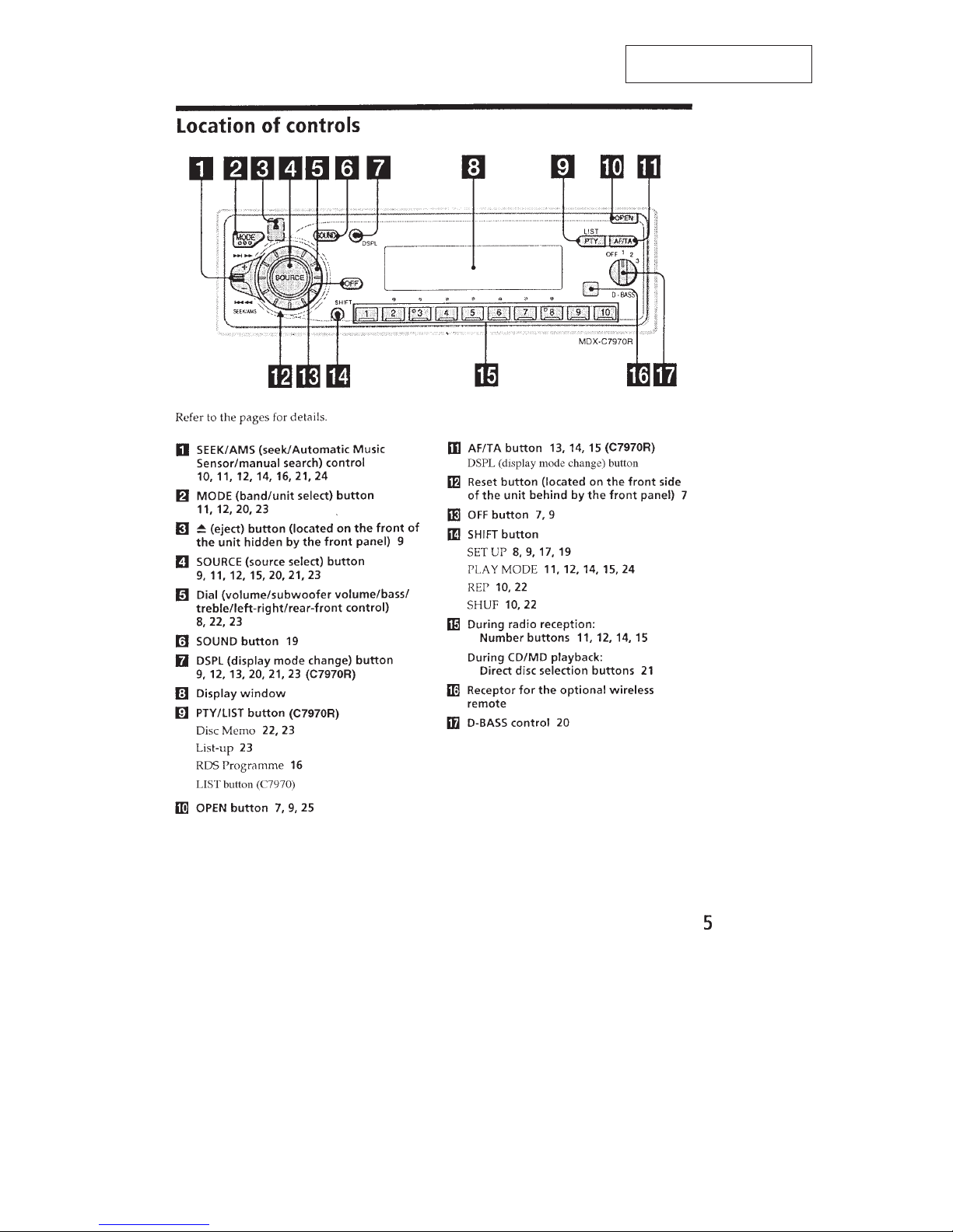
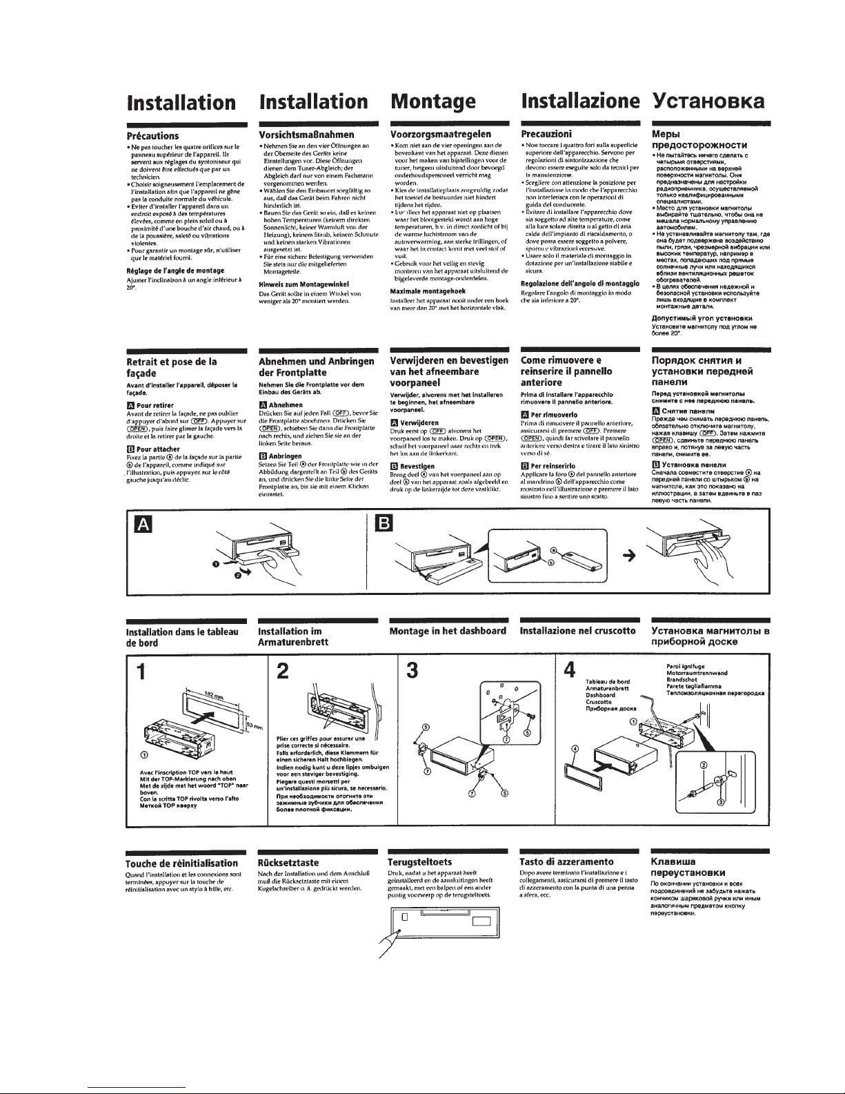
Location of Controls ....................................................... 4
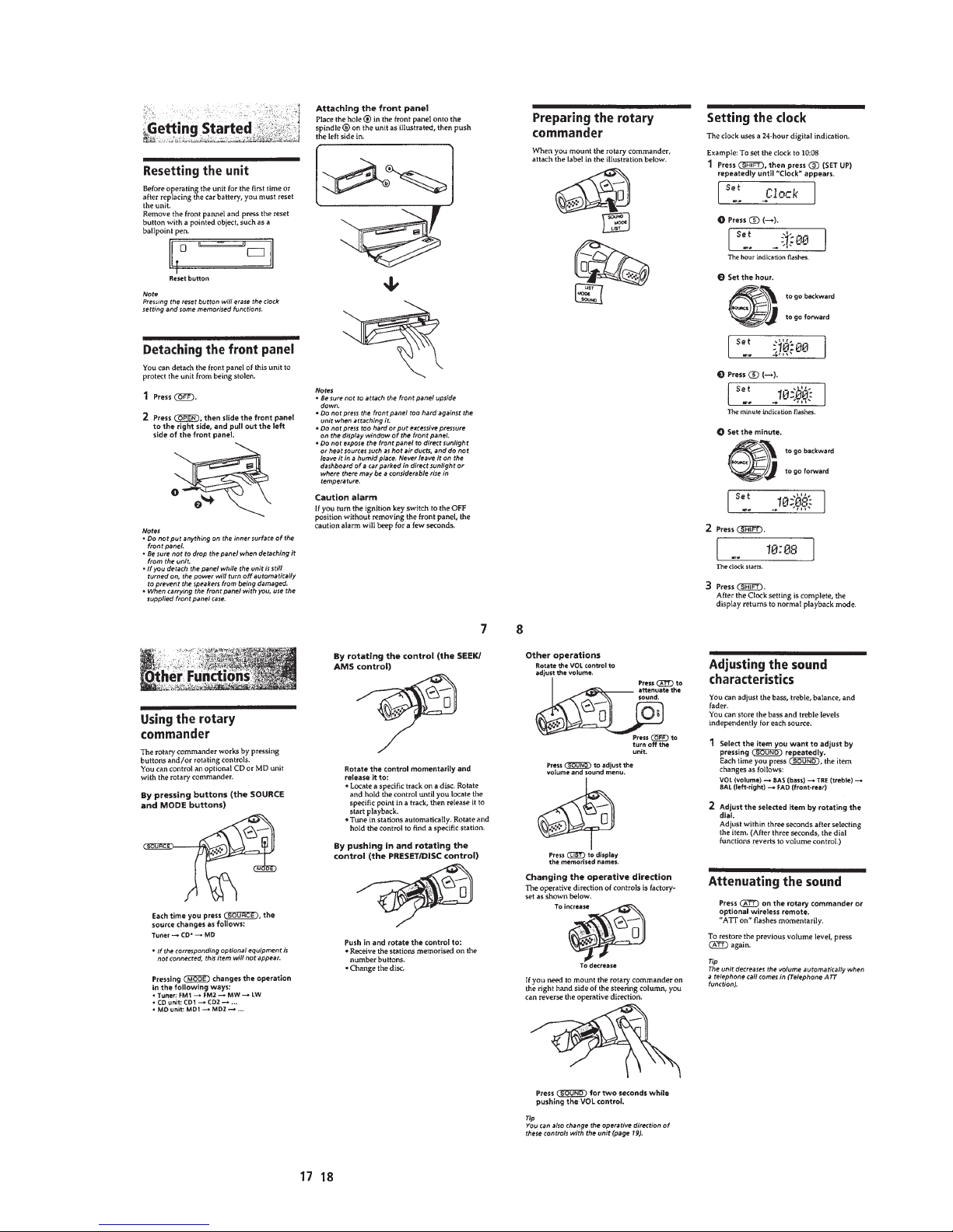
Resetting the Unit ........................................................... 5
Detaching the Front Panel............................................... 5
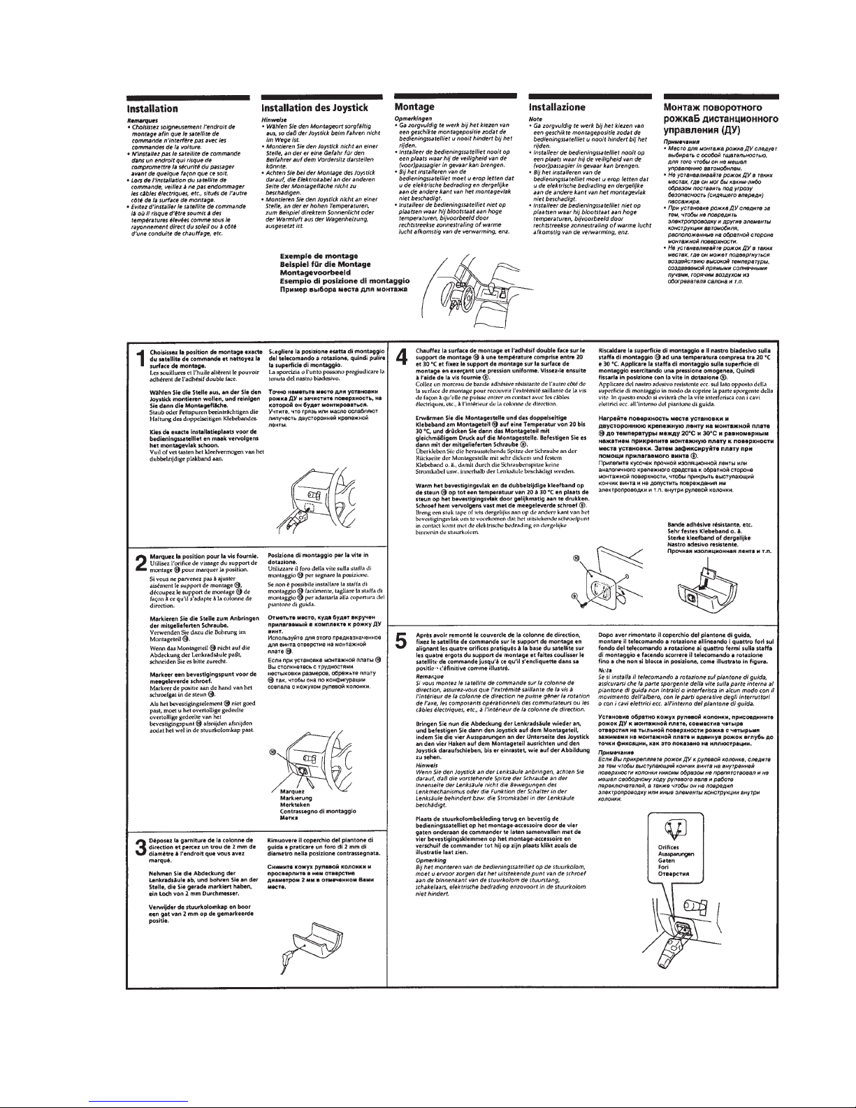
Preparing the Rotary Commander .................................. 5
Setting the Clock............................................................. 5
Using the Rotary Commander ........................................ 5
Adjusting the Sound Characterisitics ............................. 5
Attenuating the Sound .................................................... 5
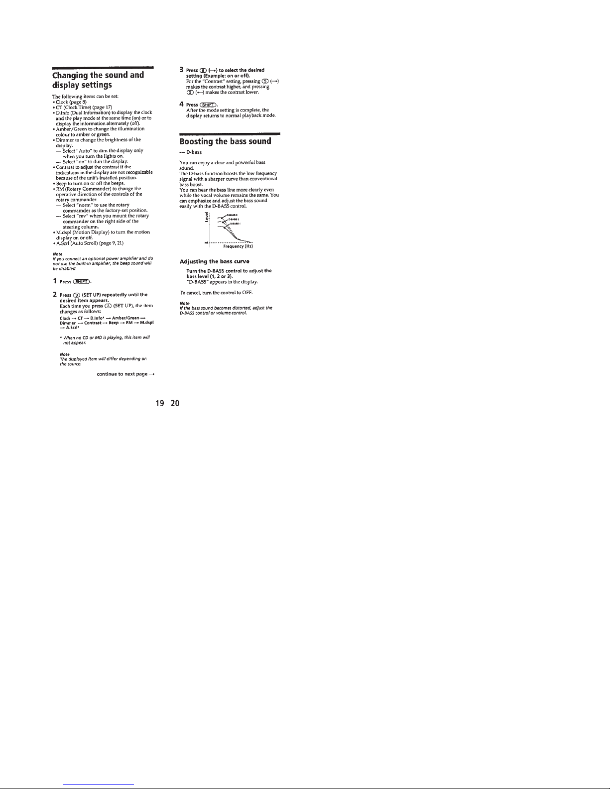
Changing the Sound and Display Settings ..................... 6
Boosting the Bass Sound ................................................ 6
Installation....................................................................... 7
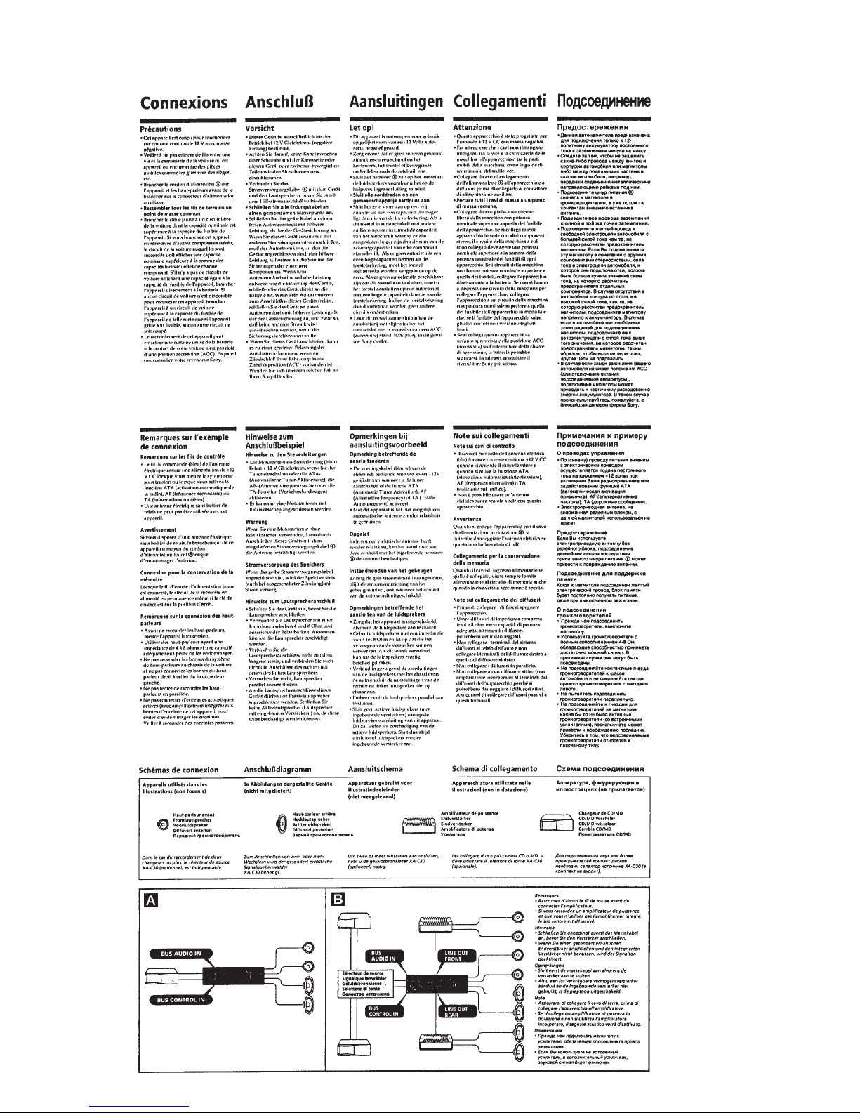
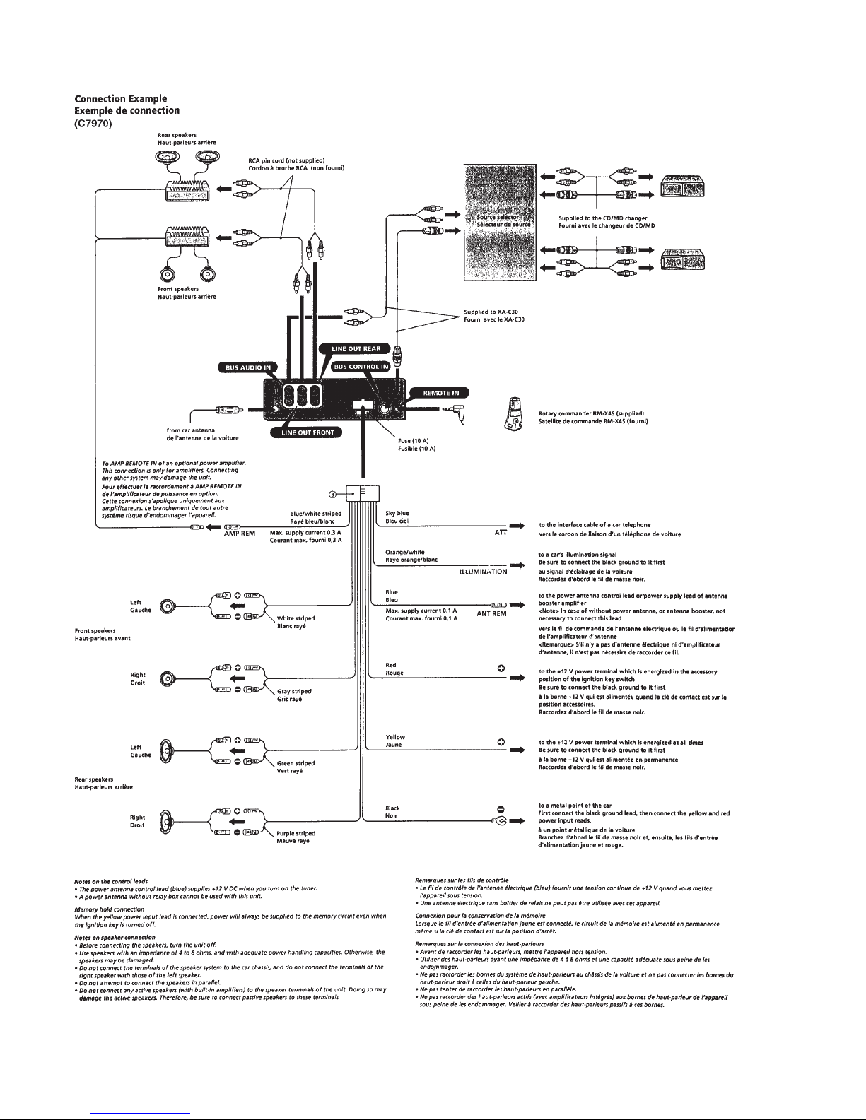
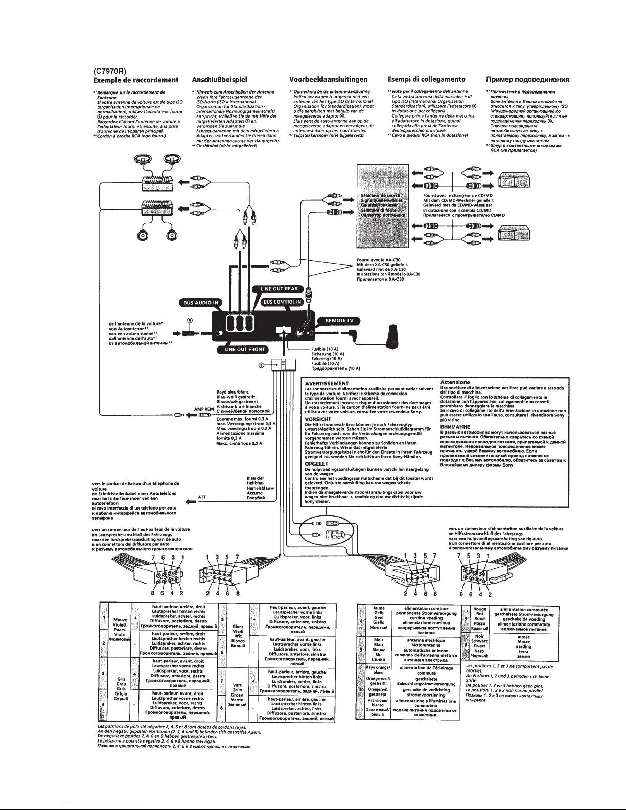
Connections..................................................................... 8
2. DISASSEMBLY ......................................................... 12
3. ELECTRICAL ADJUSTMENTS
Test Mode........................................................................ 18
MD Section ..................................................................... 18
Tuner Section .................................................................. 18
4. DIAGRAMS
4-1. Block Diagram – SERVO Section – ............................... 23
4-2. Block Diagram – TUNER Section – .............................. 25
4-3. Block Diagram – MAIN Section – ................................. 27
4-4. Block Diagram
– DISPLAY/KEY CONTROL Section –........................ 29
4-5. Block Diagram
– BUS CONTROL/POWER SUPPLY Section – ........... 31
4-6. Note for Printed Wiring Boards and
Schematic Diagrams ....................................................... 33
4-7. Printed Wiring Boards – SERVO Section – ................... 35
4-8. Schematic Diagram – SERVO Board (1/3) – ................. 37
4-9. Schematic Diagram – SERVO Board (2/3) – ................. 39
4-10. Schematic Diagram – SERVO Board (3/3) – ................. 41
4-11. Printed Wiring Board
– MAIN Board (Component Side) – .............................. 43
4-12. Printed Wiring Board
– MAIN Board (Conductor Side) – ................................ 45
4-13. Schematic Diagram – MAIN Board (1/4) – ................... 47
4-14. Schematic Diagram – MAIN Board (2/4) – ................... 49
4-15. Schematic Diagram – MAIN Board (3/4) – ................... 51
4-16. Schematic Diagram – MAIN Board (4/4) – ................... 53
4-17. Printed Wiring Board – DISPLAY Board – ................... 55
4-18. Schematic Diagram – DISPLAY Board – ...................... 57
4-19. Printed Wiring Board – SUB Board – ............................ 59
4-20. Schematic Diagram – SUB Board – ............................... 61
4-21. IC Pin Function Description ........................................... 69
5. EXPLODED VIEWS ................................................ 79
6. ELECTRICAL PARTS LIST ............................... 83
TABLE OF CONTENTS
– 4 –
SECTION 1
GENERAL
This section is extracted from
instruction manual.
– 5 –
– 6 –
– 7 –
– 8 –
– 9 –
– 10 –
– 11 –
– 12 –
SECTION 2
DISASSEMBLY
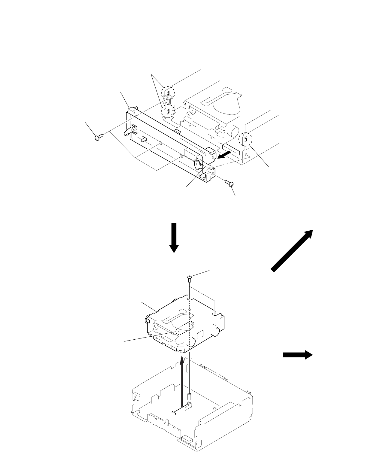
SUB PANEL ASS’Y
Note: Follow the disassembly procedure in the numerical order given.
MECHANISM DECK (MG-164N-138)
2
two claws
4
sub panel ass’y
1
three screws
(PTT2.6 × 6)
3
connector
(CN901)
2
cla
w
1
screw
(PTT2.6 × 6)
1
two screws
(PTT2.6
×
4)
3
mechanism deck
(MG-164N-138)
2
connector
(CN200)
– 13 –
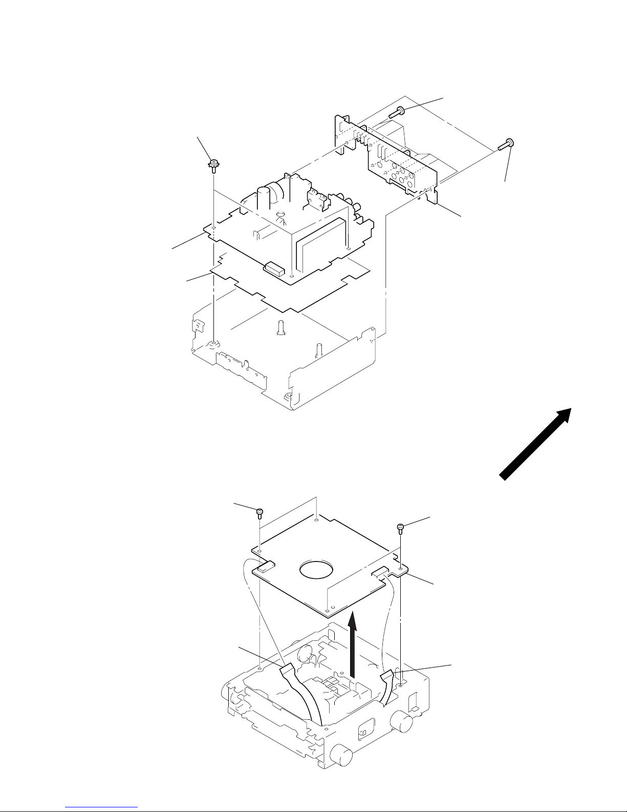
MAIN BOARD, HEAT SINK
SERVO BOARD
2
two screws
(BVTT2
×
4)
1
sensor flexible board
(CN102)
2
two screws
(BVTT2
×
4)
1
flexible boar
d
(CN103)
3
servo board
4
insulating sheet
3
main board
2
three screws
(PTT2.6 × 6) (ground point)
1
two screws
(PTT2.6 × 10)
6
heat sink
5
eight screws
(PTT2.6 × 10)
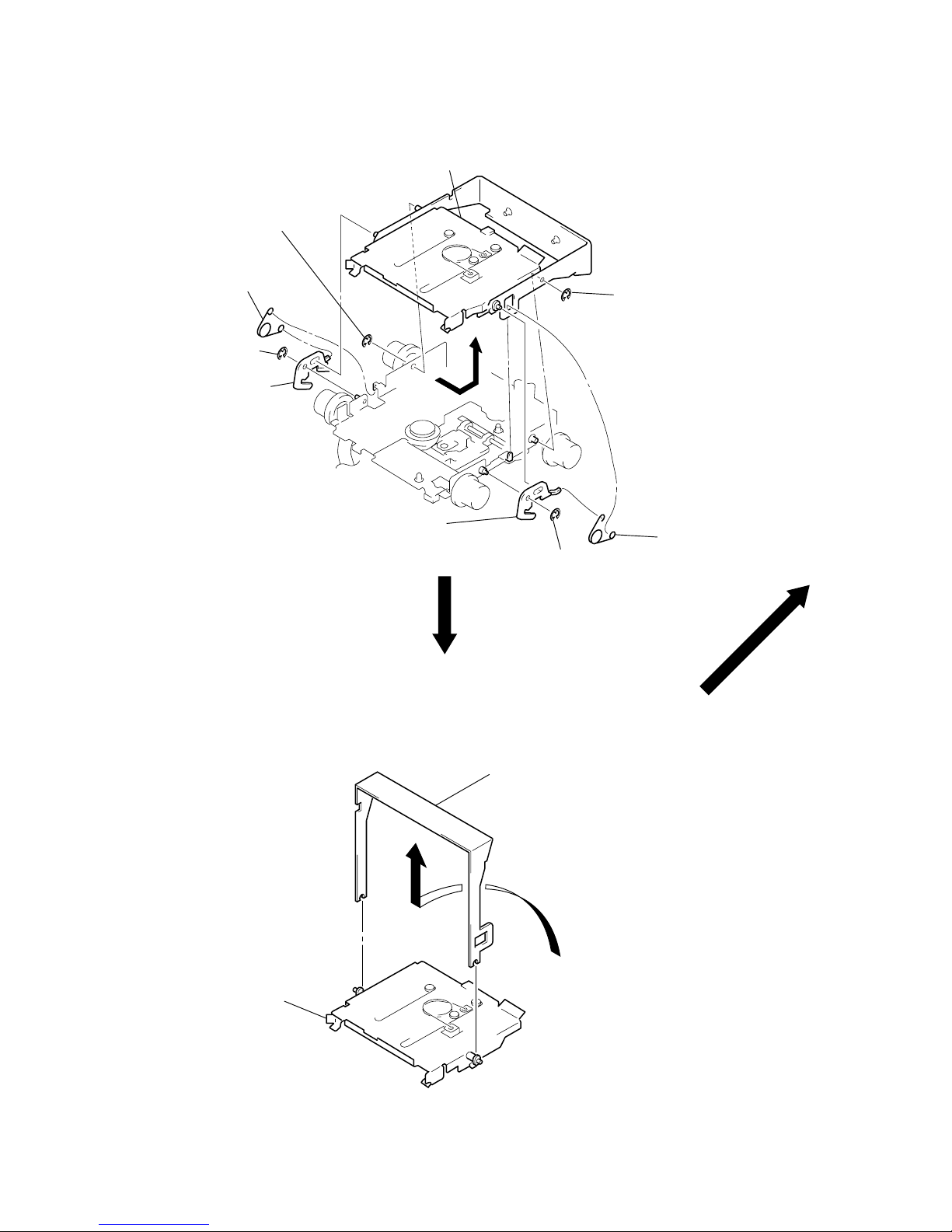
– 14 –
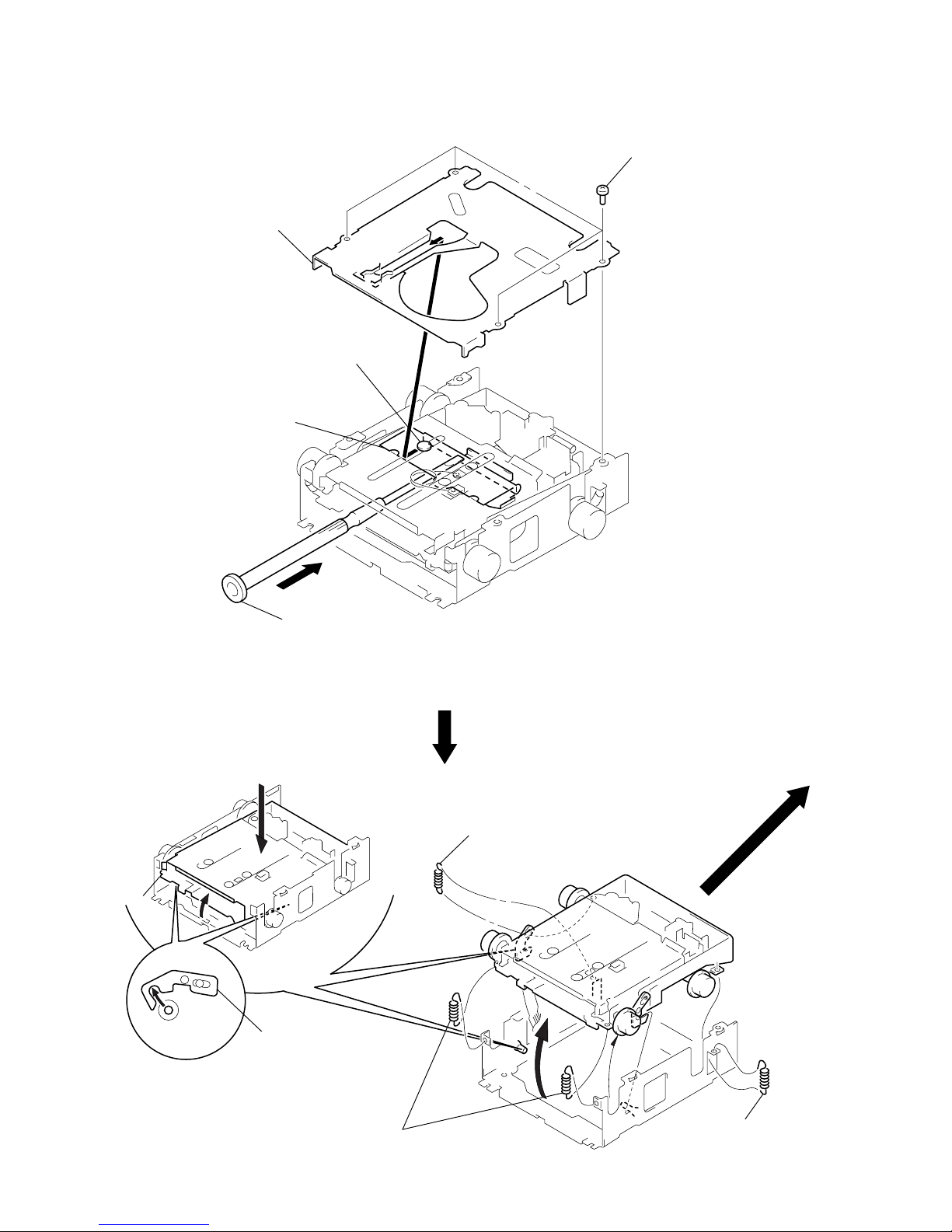
MD COVER ASS’Y
FLOAT BLOCK
1
four screws
(B2
×
3)
3
MD cover ass’y
2
Pushing the Cassette Holder toward the direction A with a
screwdriver, etc., disengage the Shaft (MD Cover Guide) from
the slot in the MD Cover Ass’y.
Note:Take care not to scratch the Optiocal Pick-up when pushing
the Cassette Holder with a screwdriver. etc.
shaft (MD cover guide)
cassette holder
A
1
tension spring (FL2)
1
tension spring (FL2
)
2
two tension springs (FLOAT F)
3
Pushing an arrow A part, raise the float block
up ward at the front to release a lock.
A
float block
lever (lock R)
lever (lock L)
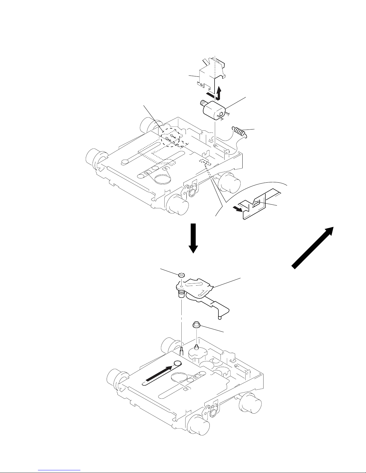
– 15 –
LO MOTOR ASS’Y (LOADING) (M903)
LEVER (LE) ASS’Y
4
Remove the bracket (LO)
in the direction of the arrow
A
.
1
Remove solders of motor. (M903)
5
LO motor ass’y (loading)
(M903)
2
tension spring (rack)
3
claw
A
2
stopper washer
2
lever (LE) ass’y
3
roller (GLE)
1
– 16 –
HOLDER ASS’Y
CHUCKING ARM ASS’Y
1
Remove the chucking arm ass’y
in the direction of the arrow.
holder ass’y
2
type-E stop ring 1.5
2
type-E stop ring 1.5
3
lever (lock L)
2
type-E stop ring 1.5
2
type-E stopring 1.5
4
Remove the holder ass’y in the
direction of the arrow.
1
spring (CHKG)
1
spring (CHKG)
3
lever (lock R)

– 17 –
OPTICAL PICK-UP (KMS-241B/J1NP)
SL MOTOR ASS’Y (SLED) (M902), SP MOTOR ASS’Y (SPINDLE) (M901)
6
bearing (SL)
5
feed screw ass’
y
3
screw
(K2 × 3)
2
shaft (SL2)
1
two screws
(K2 × 3)
7
optical pick-up
(KMS-241B/J1NP)
4
screw
(B2 × 3)
4
screw
(P1.7 × 1.8)
5
bracket (SL)
9
two screws
(P1.7 × 1.8)
!º
retainer (SP)
!¡
SP motor ass’y
(spindle) (M901)
7
screw
(B2 × 3)
2
two screws
(2 × 8)
3
sensor board
1
Remove solders of motors.
(M901, M902)
8
base (SL)
6
SL motor ass’y
(sled) (M902)
– 18 –
TEST MODE
This set have the test mode function. In the test mode, FM Auto
Scan/Stop Level and AM (MW) Auto Scan/Stop Lev el adjustments
can be performed easier than it in ordinary procedure.
<Set the Test Mode>
1. Turn ON the regulated po wer supply . ( The clock is displayed)
Note: Press the [OFF] button, if the clock is not displayed.
2. Push the preset [4] button.
3. Push the preset [5] button.
4. Press the preset [1] button for more than two seconds.
5. Then the display indicates all lights, the test mode is set.
<Release the Test mode>
1. Push the [OFF] button.
MD SECTION
MD section adjustments are done automatically in this set.
3. Adjust the volume RV2 on TU1 by turning clockwise untill
“0” is shown next to “FM” on the display window, If “0” is
already shown or the volume RV2 has been turned too far,
turn it back counterclockwise untill “0” is disappeared once,
then try this adjustment.
Display
SECTION 3
ELECTRICAL ADJUSTMENTS
See the adjustment location from on page 22 for the adjustment.
TUNER SECTION
0 dB=1 µV
Cautions during repair
When the tuner unit is defective, replace it by a new one because its internal block is difficult to repair.
Note: Adjust the tuner section in the sequence shown below.
1. FM Auto Scan/Stop Level Adjustment
2. FM Stereo Separation Adjustment (MDX-C7970)
3. FM Stereo Separation Adjustment (Wide) (MDX-C7970R)
4. FM Stereo Separation Adjustment (Narrow) (MDX-C7970R)
5. FM RDS S-Meter Adjustment (MDX-C7970R)
6. AM (MW) Auto Scan/Stop Level Adjustment
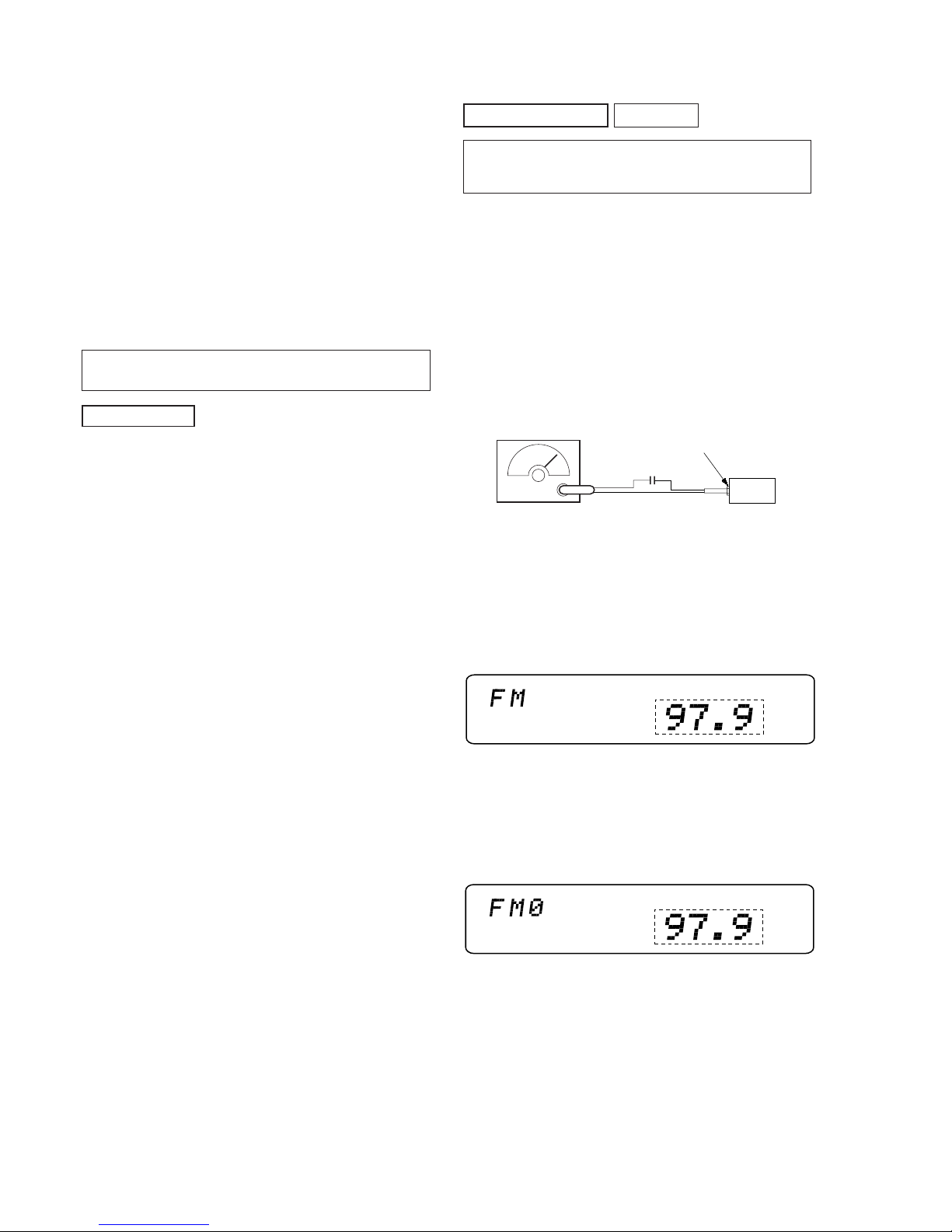
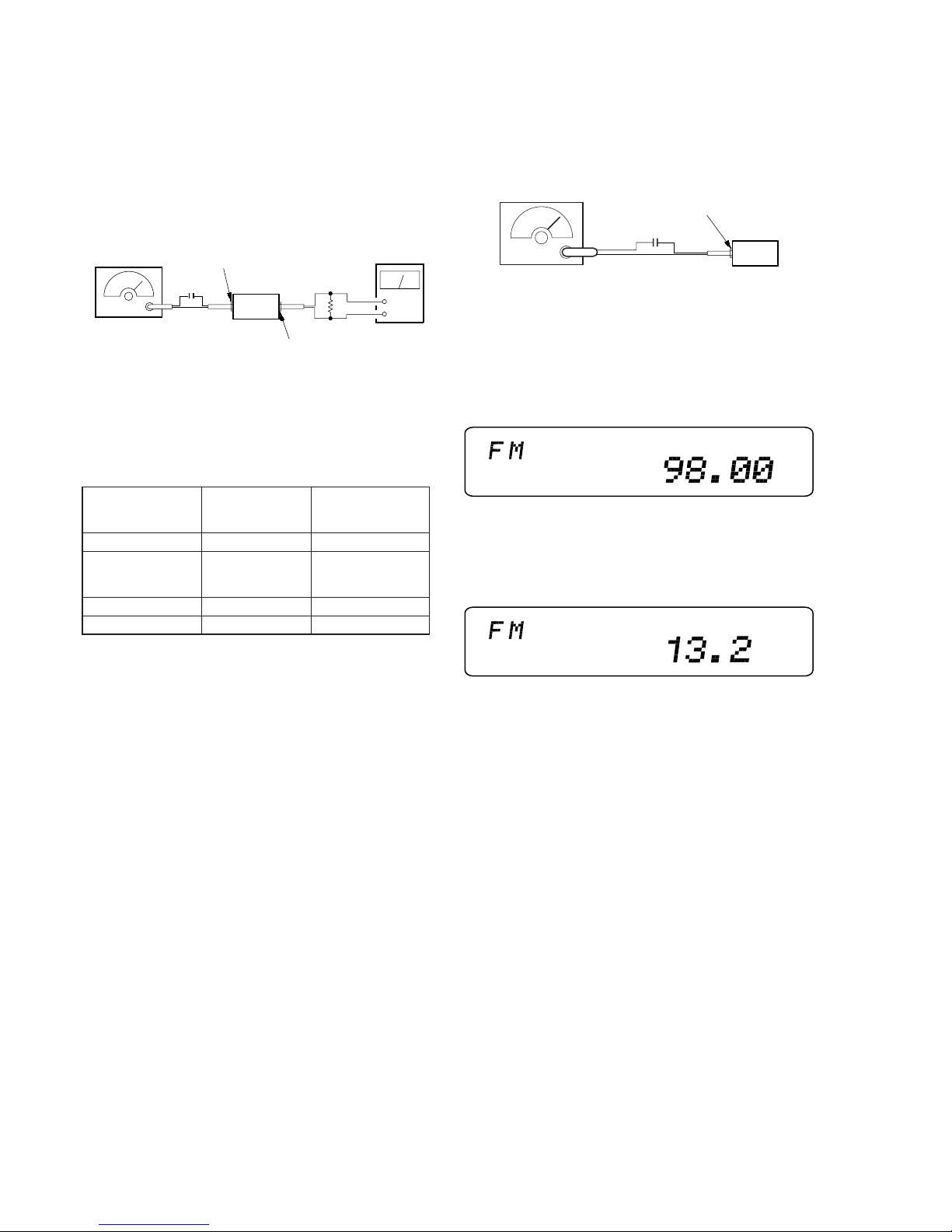
FM Auto Scan/Stop Level Adjustment
Setting:
[SOURCE] button : FM
FREQUENCY SELECT switch: FM 200 k (E model)
Procedure:
1. Set to the test mode.
2. Push the
[SOURCE] button and set to FM.
Display
set
antenna jack (CN1)
FM RF signal
generator
Carrier frequency: 97.9 MHz (MDX-C7970)
98.0 MHz (MDX-C7970R)
Output level : 22 dB (12.6
µ
V)
Mode : mono
Modulation : 1 kHz, 22.5 kHz deviation (30%)
0.01
µ
F
SHUF
*1
SHUF
*1
*1: MDX-C7970R indicates “98.00”.
Adjustment Location: See page 22.
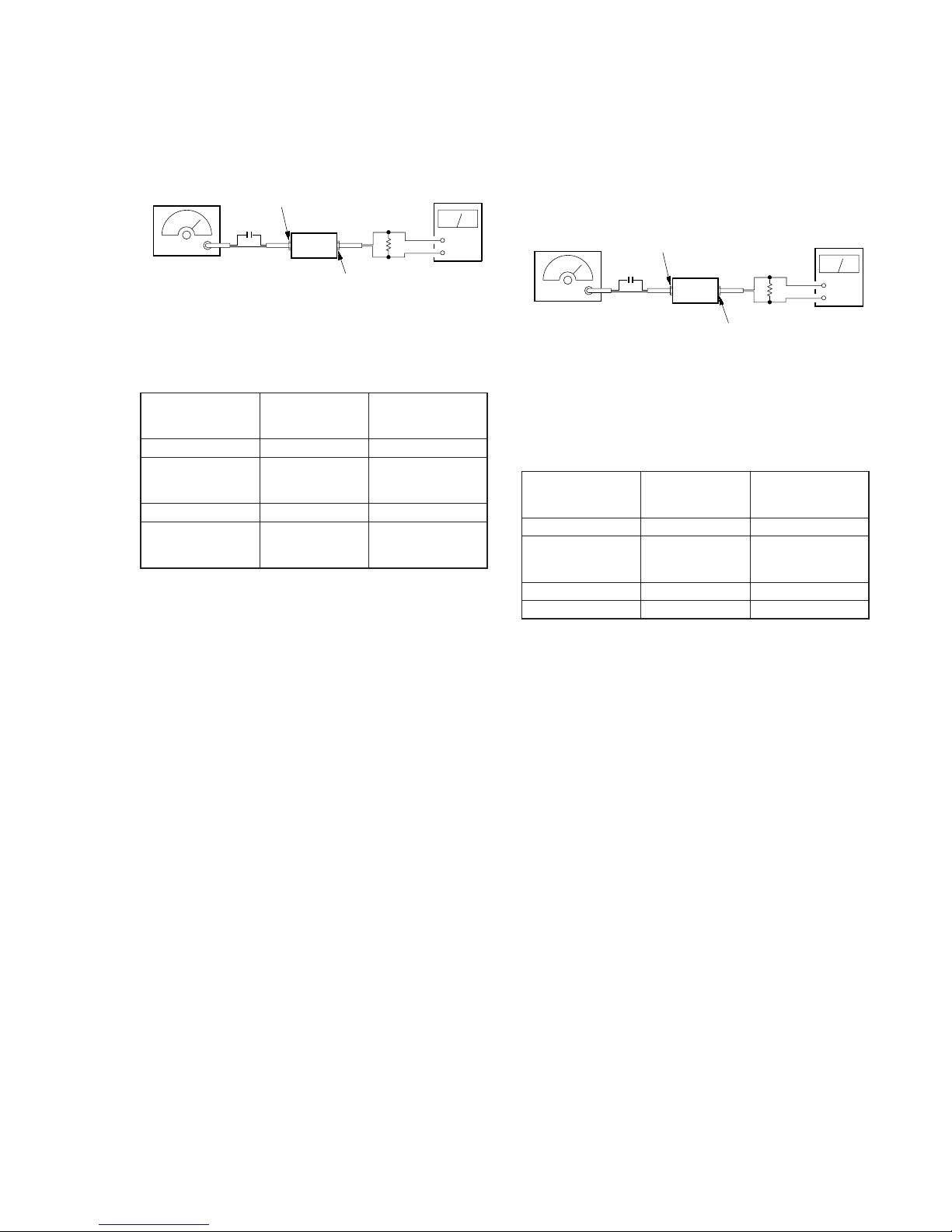
– 19 –
FM Stereo
Level meter Level meter
signal generator
connection reading (dB)
output channel
L-CH L-CH A
B
L-CH R-CH Adjust RV3 on TU1
for minimum reading.
R-CH R-CH C
R-CH L-CH D
FM Stereo
Level meter Level meter
signal generator
connection reading (dB)
output channel
L-CH L-CH A
B
R-CH L-CH Adjust RV4 on TU1
for minimum reading.
R-CH R-CH C
D
L-CH R-CH Adjust RV4 on TU1
for minimum reading.
FM Stereo Separation Adjustment (MDX-C7970)
Setting:
[SOURCE] button : FM
FREQUENCY SELECT switch: FM 200 k (E model)
Procedure:
FM RF signal
generator
Carrier frequency : 97.9 MHz
Output level : 70 dB (3.2 mV)
Mode : stereo
Modulation : main: 1 kHz, 33.75 kHz deviation (45%)
sub : 1 kHz, 33.75 kHz deviation (45%)
: 19 kHz pilot: 7.5 kHz deviation (10%)
0.01 µF
set
antenna jack (J1)
+
–
LINE OUT jack (CNP300)
level meter
10 k
Ω
FM Stereo Separation Adjustment (Wide) (MDX-C7970R)
Setting:
[SOURCE] button : FM
[SHIFT] button : ON (light up SET UP and PLAY MODE)
Preset [4] (PLAY MODE) →
[5] (→) buttons : WIDE mode
FM RF signal
generator
Carrier frequency : 98.00 MHz
Output level : 70 dB (3.2 mV)
Mode : stereo
Modulation : main: 1 kHz, 33.75 kHz deviation (45%)
sub : 1 kHz, 33.75 kHz deviation (45%)
: 19 kHz pilot: 7.5 kHz deviation (10%)
0.01 µF
set
antenna jack (J1)
+
–
level meter
10 k
Ω
LINE OUT jack (CNP300)
(75
Ω)
Procedure:
1. Adjust the volume RV3 on FM/AM tuner unit (TU1) for the
best separation.
L-CH Stereo separation: A-B
R-CH Stereo separation: C-D
The separations of both channels should be equal.
Specification: Separation more than 24 dB
Adjustment Location: See page 22.
L-CH Stereo separation: A-B
R-CH Stereo separation: C-D
The separations of both channels should be equal.
Specification: Separation more than 30 dB
Adjustment Location: See page 22.
– 20 –
FM Stereo
Level meter Level meter
signal generator
connection reading (dB)
output channel
L-CH L-CH A
B
L-CH R-CH Adjust RV4 on TU1
for minimum reading.
R-CH R-CH C
R-CH L-CH D
FM Stereo Separation Adjustment (Narrow)
(MDX-C7970R)
Setting:
[SOURCE] button : FM
[SHIFT] button : ON (light up SET UP and PLAY MODE)
Preset [4] (PLAY MODE) →
[5] (→) buttons : NARROW mode
FM RF signal
generator
Carrier frequency : 98.00MHz
Output level : 70 dB (3.2 mV)
Mode : stereo
Modulation : main: 1 kHz, 20 kHz deviation (26.7%)
sub : 1 kHz, 20 kHz deviation (26.7%)
: 19 kHz pilot: 7.5 kHz deviation (10%)
0.01 µF
set
antenna jack (J1)
+
–
level meter
10 k
Ω
(75
Ω)
LINE OUT jack (CNP300)
FM RDS S-Meter Adjustment (MDX-C7970R)
Setting:
[SOURCE] button : FM
Procedure:
1. Set to the test mode. (See page 18)
2. Push the
[SOURCE] button and set to FM.
Display
set
antenna jack (J1)
FM RF signal
generator
Carrier frequency : 98.00 MHz
Output level : 35 dB (56.2
µ
V)
Mode : mono
Modulation : no modulation
0.01
µ
F
SHUF
SHUF
Procedure:
1. Adjust the volume RV4 on FM/AM tuner unit (TU1) for the
best separation.
3. Push the preset
[10] button .
4. Adjust RV1 on MAIN board so that the display indication is
“13.2”.
Display
Specification: Display indication: 13.0 to 13.4
Adjustment Location: See page 22.
L-CH Stereo separation: A-B
R-CH Stereo separation: C-D
The separations of both channels should be equal.
Specification: Separation more than 18 dB
Adjustment Location: See page 22.
– 21 – – 22 –
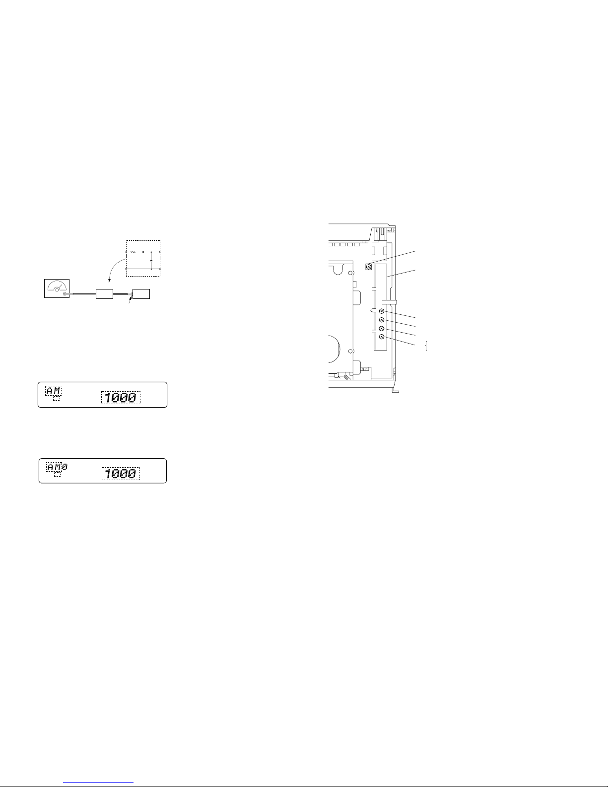
MW Auto Scan/Stop Level Adjustment
Setting:
[SOURCE] n [MODE] button : AM (MDX-C7970)
MW (MDX-C7970R)
FREQUENCY SELECT switch : AM 10 k (E model)
Procedure:
1. Set to the test mode. (See page 18)
2. Push the
[SOURCE] button and set to FM.
3. Push the
[MODE] button and set to AM or MW.
Display
4. Adjust with the volume RV1 on TU1 so that the “AM” or “MW”
indication turns to “AM0” or “MW0” indication on the display window.
But, in case of alredy indicated “AM0” or “MW0”, turn the
RV1 so that put out light “0” indication and adjustment.
Display
*2: MDX-C7970R indicates “MW”.
*3: MDX-C7970R indicates “999”.
*4: Only MDX-C7970R indicates.
Adjustment Location: See page 22.
AM RF signal
generator
Carrier frequency : 1000 kHz (MDX-C7970)
999 kHz (MDX-C7970R)
30% amplitude
modulation by
1 kHz signal
Output level : 33 dB
(
44.7 µV
)
(50 Ω)
set
AM dummy antenna
30
Ω
15 pF
65 pF
antenna jack (J1)
SHUF
TP
*3
*2
*4
SHUF
TP
*3
*2
*4
Adjustment Location:
– SET UPPER VIEW –
RV1 RDS S-Meter Adjustment (MDX-C7970R)
TU1
RV1 AM (MW) Auto Scan/Stop Level Adjustment
RV2 FM Auto Scan/Stop Level Adjustment
FM Stereo Separation Adjustment (MDX-C7970)
FM Stereo Separation Adjustment (Narrow) (MDX-C7970R)
RV3 FM Stereo Separation Adjustment (Wide) (MDX-C7970R)
RV4
MDX-C7970/C7970R
– 23 – – 24 –
SECTION 4
DIAGRAMS
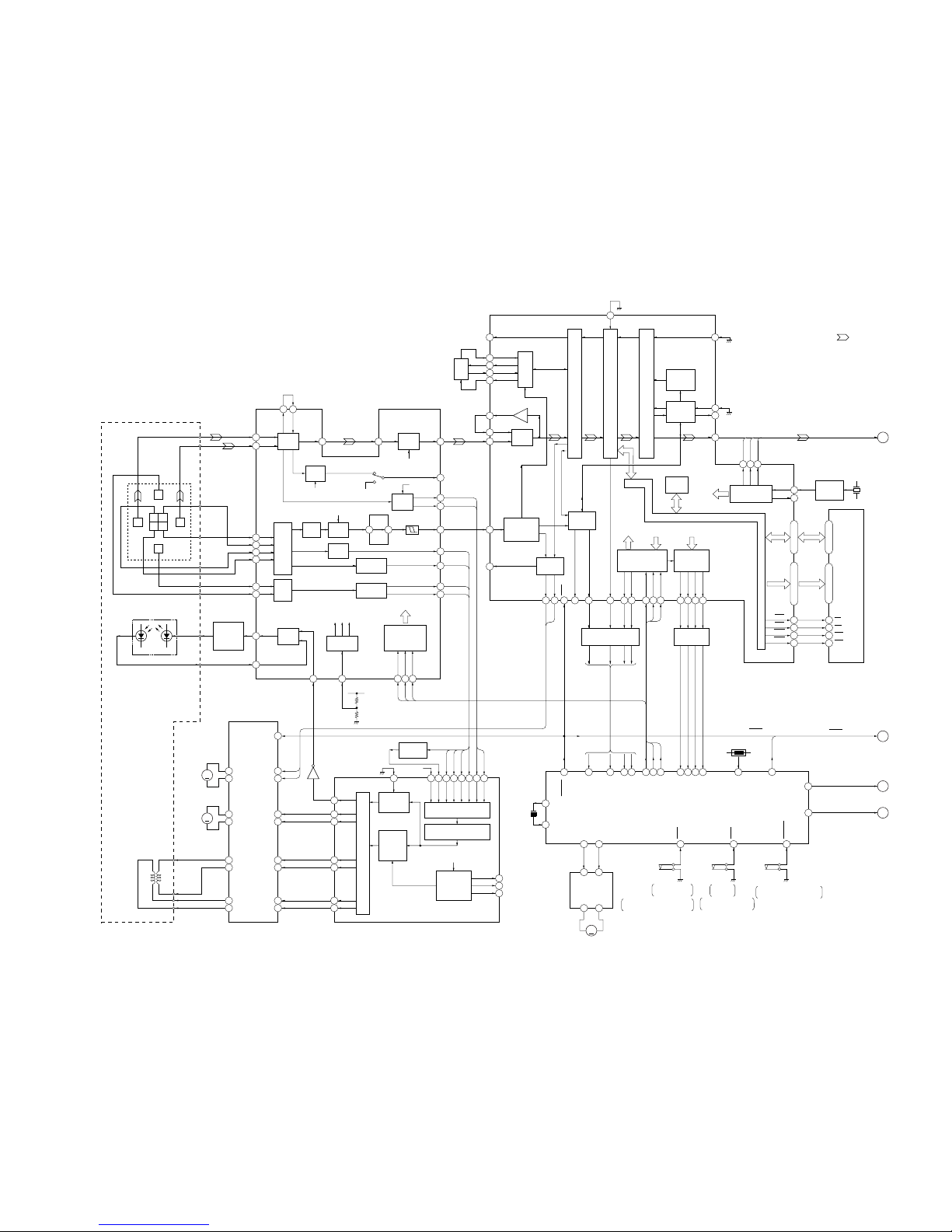
4-1. BLOCK DIAGRAM – SERVO Section –
F
C B
D A
E
I J
J
I
B
A
C
D
E
F
DETECTOR
1
2
J
I
4
5
6
7
A
B
C
D
8
9
E
F
LDPD
LASER DIODE
ILCC
PD
OPTICAL PICK-UP
(KMS-241B/J1NP)
AUTOMATIC
POWER
CONTROL
Q302
11
10
APC
PD
LD/PD
AMP
12
APCREF
I-V
AMP
I-V
AMP
AT
AMP
B.P.F.
29 30
WBL
ADFM
ADIN
32
ADFG
ABCD
AMP
FOCUS
ERROR AMP
TRACKING
ERROR AMP
35
34
26
28
ABCD
FE
TE
SE
V-I
CONVERTER
20
F0CNT
WBL3TEQ
+3.3V
SERIAL/
PARALLEL
CONVERTER,
DECODER
COMMAND
1716 18
SWDT
SCLK
XLAT
RF AMP
B.P.F.
46
RFO
40
RF AGC
& EQ
AGCI
EQ
38
RF
RF AMP,
FOCUS/TRACKING ERROR AMP
IC302
TEMP
48 47
MORFO
MORFI
3T
PEAK &
BOTTOM
WBL
33
AUX
73 62
37
PEAK
36
BOTM
FOCUS/TRACKING COIL DRIVE,
SPINDLE/SLED MOTOR DRIVE
IC303
6
8
OUT4F
OUT4R
M
M901
(SPINDLE)
27
25
OUT2F
OUT2R
M
M902
(SLED)
21
23
OUT1F
OUT1R
12
10
OUT3F
OUT3R
FCS+
FCS–
TRK+
TRK–
2-AXIS
DEVICE
(TRACKING)
(FOCUS)
3
4
IN4R
IN4F
29
30
IN2F
IN2R
19
18
IN1F
IN1R
14
15
IN3F
IN3R
SPFD
SPRD
IC306
92
91
88
89
86
85
83
APCREF
SFDR
SRDR
FFDR
FRDR
TFDR
TRDR
16PSB
PWM GENERATOR
AUTOMATIC
POWER
CONTROL
DIGITAL
SERVO
SIGNAL
PROCESS
7465647566 63
ANALOG MUX
A/D CONVERTER
AUTO
SEQUENCER
13
FROM CPU
INTERFACE
DIGITAL SERVO
SIGNAL PROCESSOR
IC301 (2/2)
RECP
PEAK HOLD
Q301
+3.3V
ABCD
AUX1
AUX2
ABCD
FE
TE
SE
PEAK
BOTM
81
80
82
XLRF
CKRF
DTRF
EFM/ACIRC
ENCODER/DECODER
SHOCK PROOF
MEMORY CONTROLLER
ATRAC
ENCODER/DECODER
PLL
FILTER
59
58
61
60
FILI
PCO
CLTV
FILO
100
EFMO
23
ADDT
IC301 (1/2)
15
TX
COMPA-
RATOR
51
52
55
ASYO
ASYI
RFI
ADIP
DEMODULATOR/
DECODER
78
ADFG
SPINDLE
SERVO
79
F0CNT
94 93
SPFD
SPRD
SUBCODE
PROCESSOR
24
SAMPLING
RATE
CONVERTER
DIGITAL
AUDIO
INTERFACE
22
21
DIN
DOUT
DIGITAL SIGNAL PROCESSOR,
EFM/ACIRC ENCODER/DECODER,
SHOCK PROOF MEMORY CONTROLLER,
ATRAC ENCODER/DECODER, 2M BIT D-RAM
IC301 (1/2)
DADT
INTERNAL BUS
D-RAM
CLOCK
GENERATOR
2526 27
512FS OSC
IC304
XBCK
LRCK
FS256
BCK
LRCK
FS256
X301
22.5792MHz
16
OSCI
17
OSCO
CPU
INTERFACE
MONITOR
CONTROL
10
XRST
12
DQSY11SQSY14XINT
9 8 5 6 7
SENS
SRDT
SWDT
SCLK
XLAT
LEVEL SHIFT
IC502
51331
61242
LEVEL SHIFT
IC503
1 2 3 4
MNT0
MNT1
MNT2
MNT3
13
135
12
246
FOK
SHOCK
XBUSY
SLOCK
SWDT
SCLK
XLAT
59 62 55 54 52 45 51 64 26 27 28 29
MNT0
MNT1
MNT2
MNT3
67
A-MUTE
21
LOCK
39
TEMP
MD-RST
SQSY
CC-XINT
SENS
MD-SI
MD-SO
MD-CKO
MD-LAT
7 6
EJECT
LOAD
5 4
05
1 7
M
RIN FIN
OUT1 OUT2
LOADING
MOTOR DRIVE
IC305
M903
(LOADING)
63
C-SW
LOADING START/
EJECT END
E-SW
LIMIT-IN
(LIMIT)
LOADING
END
ON:When the disc loading start
and the disc eject completion.
ON:When completion of
the disc loading.
ON:When the optical pick-up is
inner position.
31
32
EXTAL
XTAL
X501
10MHz
TH501
66
DEEMP
47, 46, 48, 49
1, 2, 24, 25
D0 – D3
32 – 29, 34 – 38, 43
9 – 12, 14 – 18, 5
A0 – A9
D0 – D3A00 – A09
41 22
45 3
44 4
42 23
XOE
XWE
XRAS
XCAS
OE
WE
RAS
CAS
D-RAM
IC307
(Page 27)
A
DADT, BCK, LRCK, FS256
(Page 27)
C
LOCK
MD-ATT
(Page 27)
D
(Page 27)
B
EMPHASIS
MD MECHANISM CONTROLLER
IC501 (1/2)
• SIGNAL PATH
: MD PLAY
11 56
RESET, EMPHASIS
RESET
MDX-C7970/C7970R
– 25 –
– 26 –
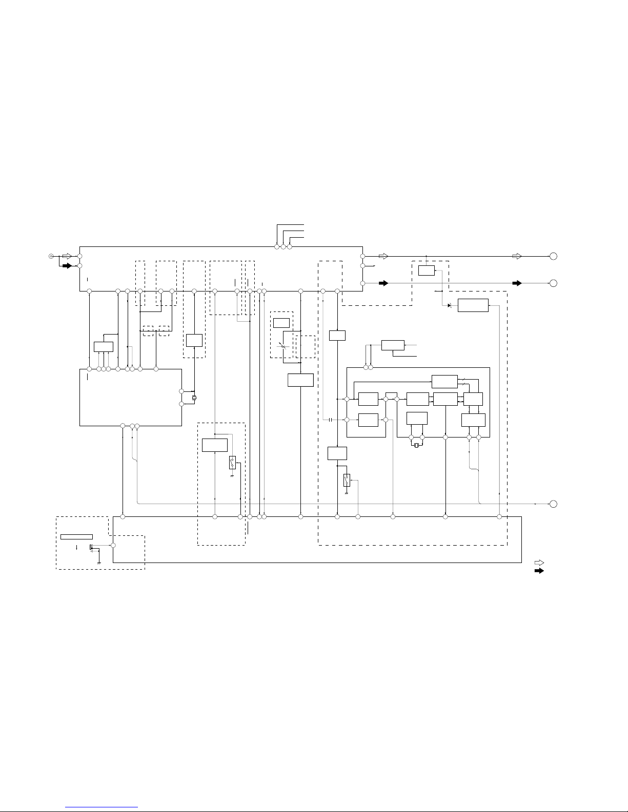
4-2. BLOCK DIAGRAM – TUNER Section –
1
4
2
FM-ANT
AM-ANT
6
VCO
21
FM/AM-IF
20
SD
5
5 283
24
10
16
9
13 12
69
100
15
68
VT
13
AM OSC
24
DATA
CLOCK
SSTOP
SDA
OSCOUT
OSCIN
SCL
SSTOP
BAND (9K-10K)
WIDE
53
S-METER (VSM)
SD-IN
83
ST-MONO
62
TU-ATT
LP AM
2
LP HC
1
LP FM
LP OUT
FM IN
25
AM IN
IF FM
14
IF AM
NARROW
51
QUALITY
35
NS-MASK
14
VDDA
7
VDDD
81
19
S-METER15S-METER (RDS)
18
16
12
FM-LCH
FM-RCH
(C7970R) (C7970R)
AM-DET
23
FM-DET
FILTER
AM OSC
BUFFER
Q4
X1
10.25MHz
FM/AM PLL
IC100
05
• SIGNAL PATH
: FM
: AM (MW/LW)
MUTING
Q101
BUFFER
Q50
MUTING
CONTROL SWITCH
Q103
BAND-PASS
FILTER
IC101
R-CH
R-CH
D5
FM/AM TUNER UNIT
TU1
MASTER CONTROLLER
IC700 (1/4)
LO/DX
11
SEEK13SEEK
22
ST/MONO
SEEK
FM/AM SIGNAL
METER BUFFER
Q1
B+ SWITCH
Q51
J1
(FM/AM ANTENNA)
8
FM +B
FM B+
FM B+
10
AM +B
AM B+
TUNER B+
BACKUP +5V
9
+B
WIDE/NARROW
SWITCH
Q7
66
82
Q8
WIDE/
NARROW
SWITCH
WIDE/NARROW
52
MPDH (MTP)
67
DAVN
RDS DECODER
IC102
INTERFACE
REGISTER
IIC BUS
SLAVE
TRANSCEIVER
OSCILLATOR
& CLOCK
X2
4.332MHz
4
8
5
OSCI
OSCO
10
9
SDA
SCL
DAVN
57 kHz
BAND-PASS
FILTER
CLOCKED
COMPARATOR
RDS/RDBS
DEMODULATOR
& DECODER
SIGNAL
QUALITY
DECODER
16
18
19
MPX
CIN
4
5
SC
OUT
MULTI
PATH
DETECTOR
20
2
LVIN
MPTH
Q5
NOISE DET
DISCHARGE
SWITCH
FM RDS
S-METER
RV1
(C7970: E model)
(C7970R)
(C7970)
(C7970)(C7970R)(C7970)(C7970)
(C7970)
(C7970R)
21
FM-IF
(C7970R)
11
AM-IF
(C7970R)
DATA
CLOCK
DATA, CLOCK
(Page 27)
G
FM
(Page 27)
E
AM
(Page 27)
F
S701
MW 10K/FM 200K
MW 9K/FM 50K
FREQUENCY SELECT
SEEKOUT
 Loading...