

sony MDX-C7970 Service Manual
MDX-C7970/C7970R
SERVICE MANUAL
For RM-X4S (Remote Commander),
please refer to RM-X4S Service Manual
(9-925-698-∏) previously issued.
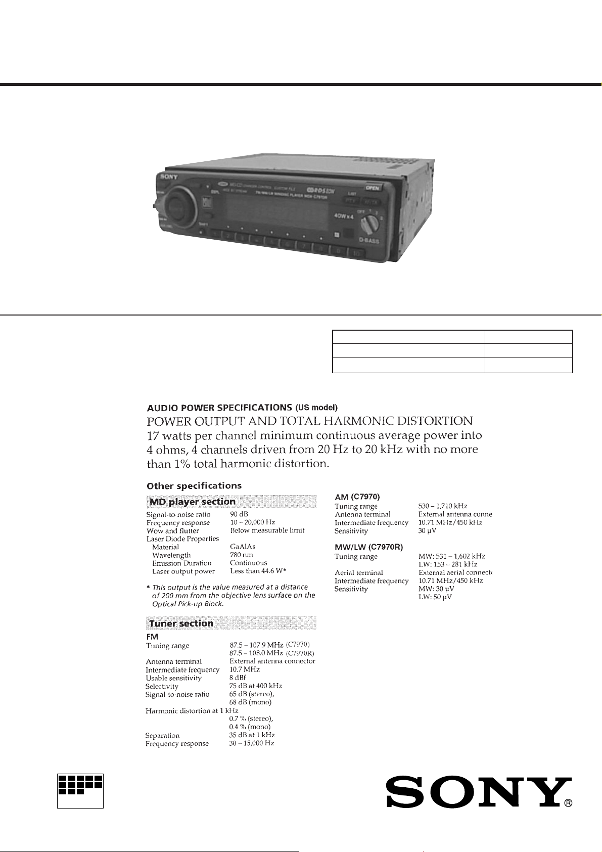
Photo: MDX-C7970R
SPECIFICATIONS
US Model
Canadian Model
E Model
MDX-C7970
AEP Model
UK Model
MDX-C7970R
Model Name Using Similar Mechanism MDX-C7900/C7900R
Base Mechanism Type MG-164N-138
Optical Pick-Up Name KMS-241B/J1NP
MICROFILM
– Continued on next page –
FM/AM(MW/LW) MINIDISC PLAYER
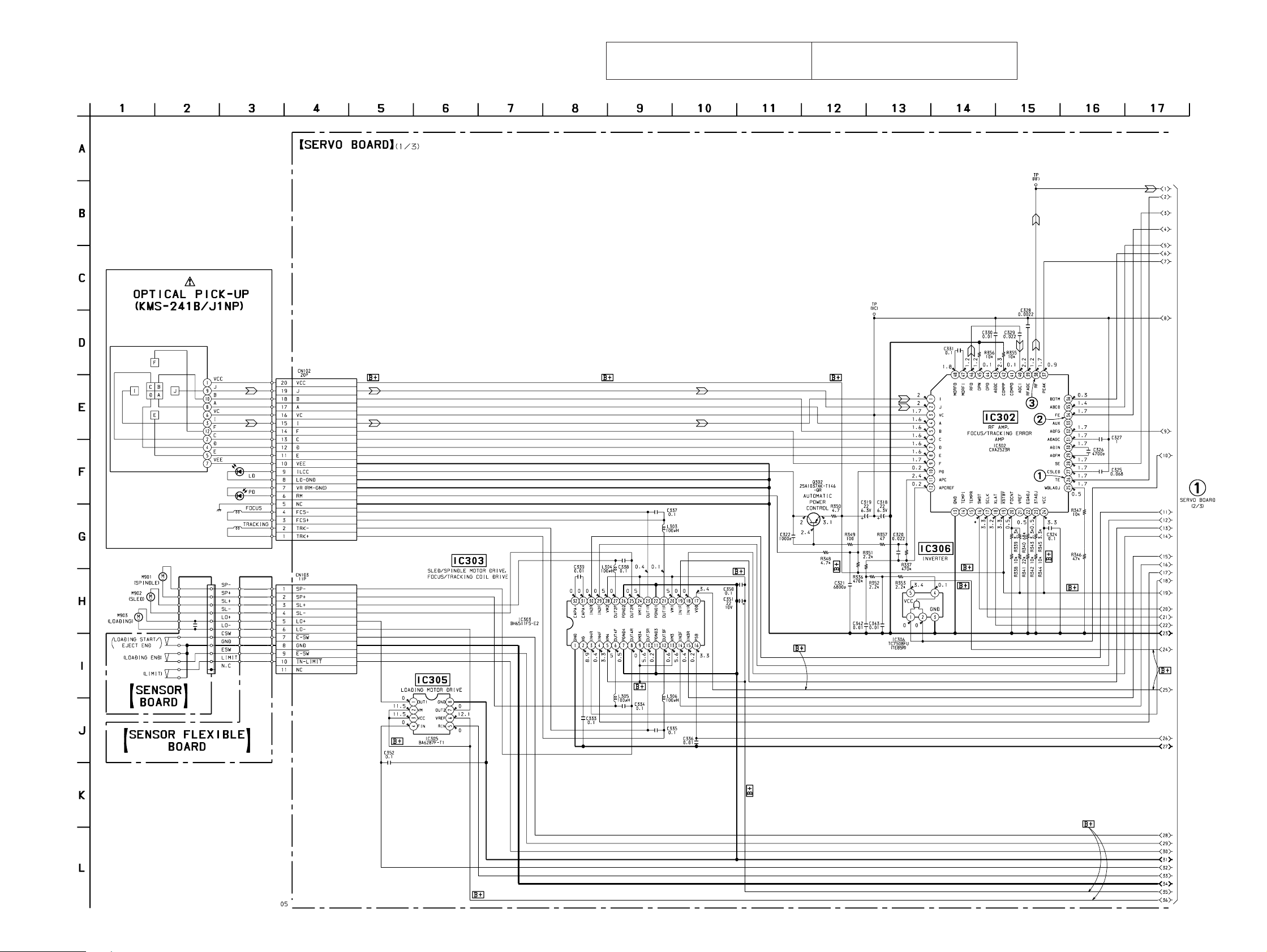
4-8. SCHEMATIC DIAGRAM – SERVO Board (1/3) –
• See page 67 for Waveforms. • See page 63 for IC Block Diagrams.
The components identified by mark ! or dotted
line with mark ! are critical for safety.
Replace only with part number specified.
Les composants identifiés par une marque ! sont
critiques pour la sécurité. Ne les remplacer que
par une piéce portant le numéro spécifié.
MDX-C7970/C7970R
• Voltages and waveforms are dc with respect to ground
under no-signal conditions.
no mark : MD PLAY
: Impossible to measure
∗
(Page 39)
– 37 – – 38 –
MDX-C7970/C7970R
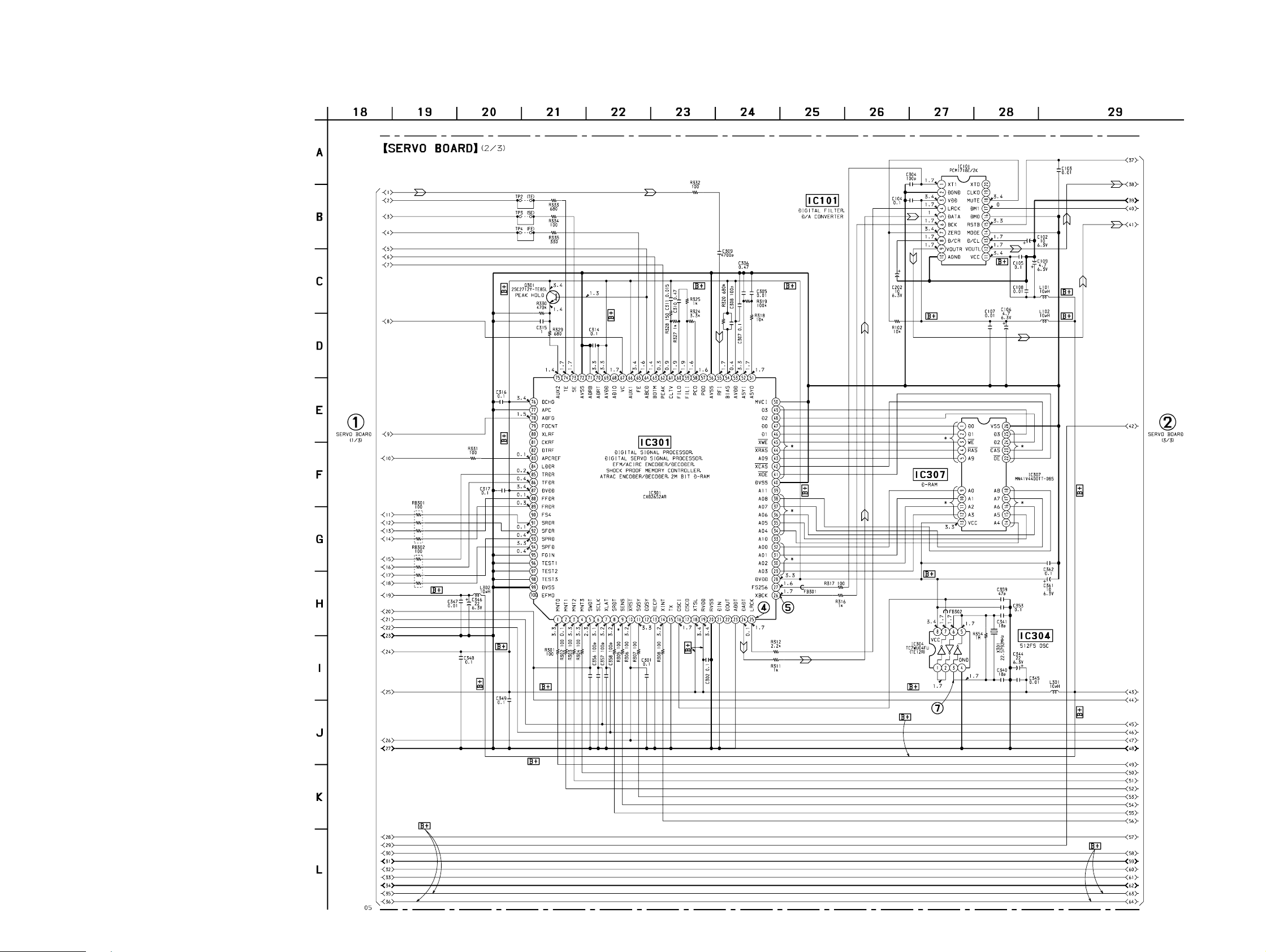
4-9. SCHEMATIC DIAGRAM – SERVO Board (2/3) – • See page 67 for Waveforms. • See page 62 for IC Block Diagrams.
• Voltages and waveforms are dc with respect to ground
under no-signal conditions.
no mark : MD PLAY
: Impossible to measure
∗
(Page 38)
(Page 41)
– 39 –
– 40 –
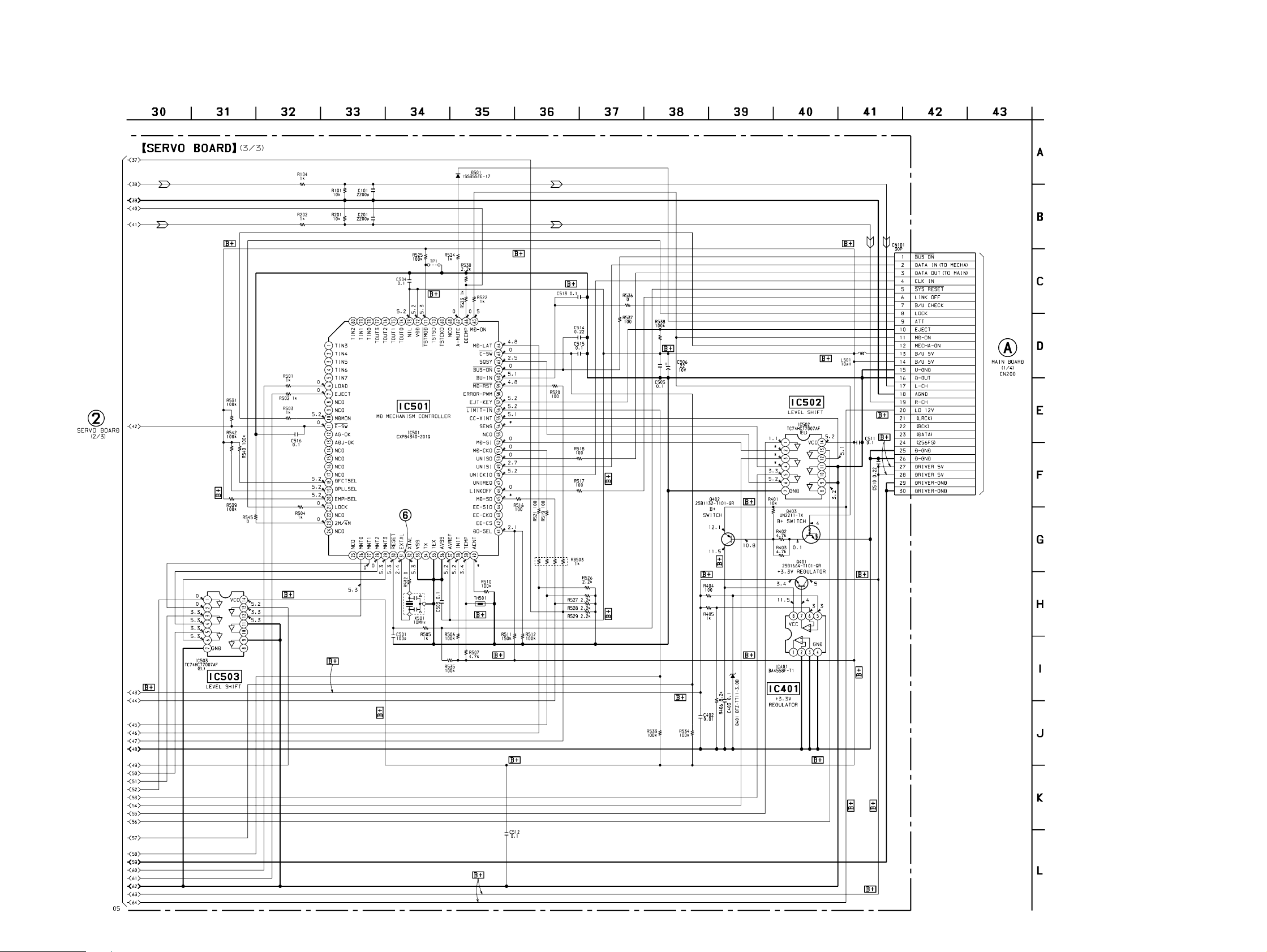
4-10. SCHEMATIC DIAGRAM – SERVO Board (3/3) – • See page 67 for Waveform.
MDX-C7970/C7970R
• Voltages and waveforms are dc with respect to ground
under no-signal conditions.
no mark : MD PLAY
: Impossible to measure
∗
(Page 40)
(Page 47)
– 41 –
– 42 –
MDX-C7970/C7970R
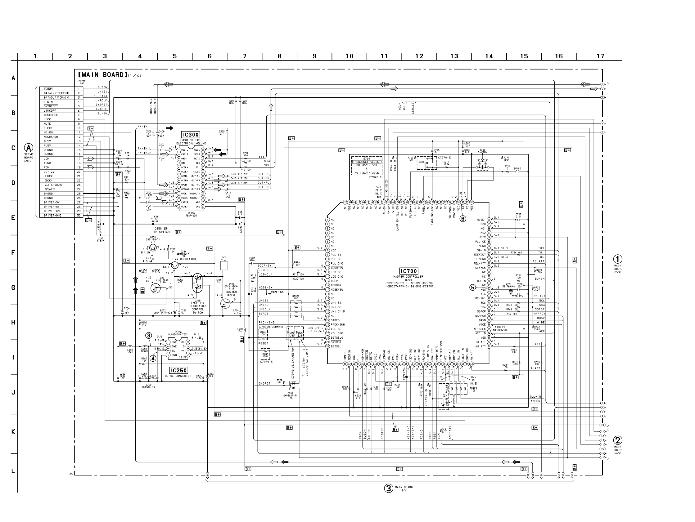
4-13. SCHEMATIC DIAGRAM – MAIN Board (1/4) – • See page 67 for Waveforms. • See page 65 for IC Block Diagrams.
(Page
42)
• Voltages and waveforms are dc with respect to ground
under no-signal (detuned) conditions.
no mark : FM
( ) : AM (MW)
[]: LW
〈〈 〉〉 : MD PLAY
(Page 49)
(Page 52)
– 47 – – 48 –
(Page 53)
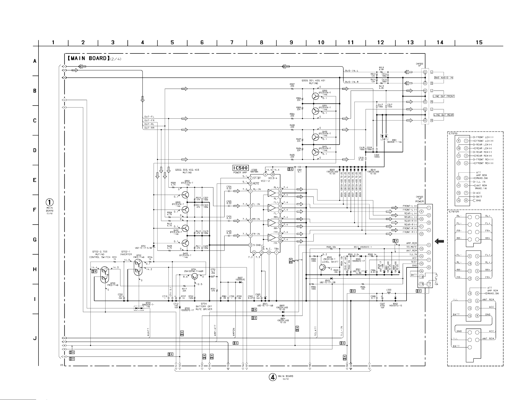
4-14. SCHEMATIC DIAGRAM – MAIN Board (2/4) –
MDX-C7970/C7970R
• Voltages are dc with respect to ground under no-signal
(detuned) conditions.
no mark : FM
(Page 48)
(Page 54)
– 49 – – 50 –
MDX-C7970/C7970R
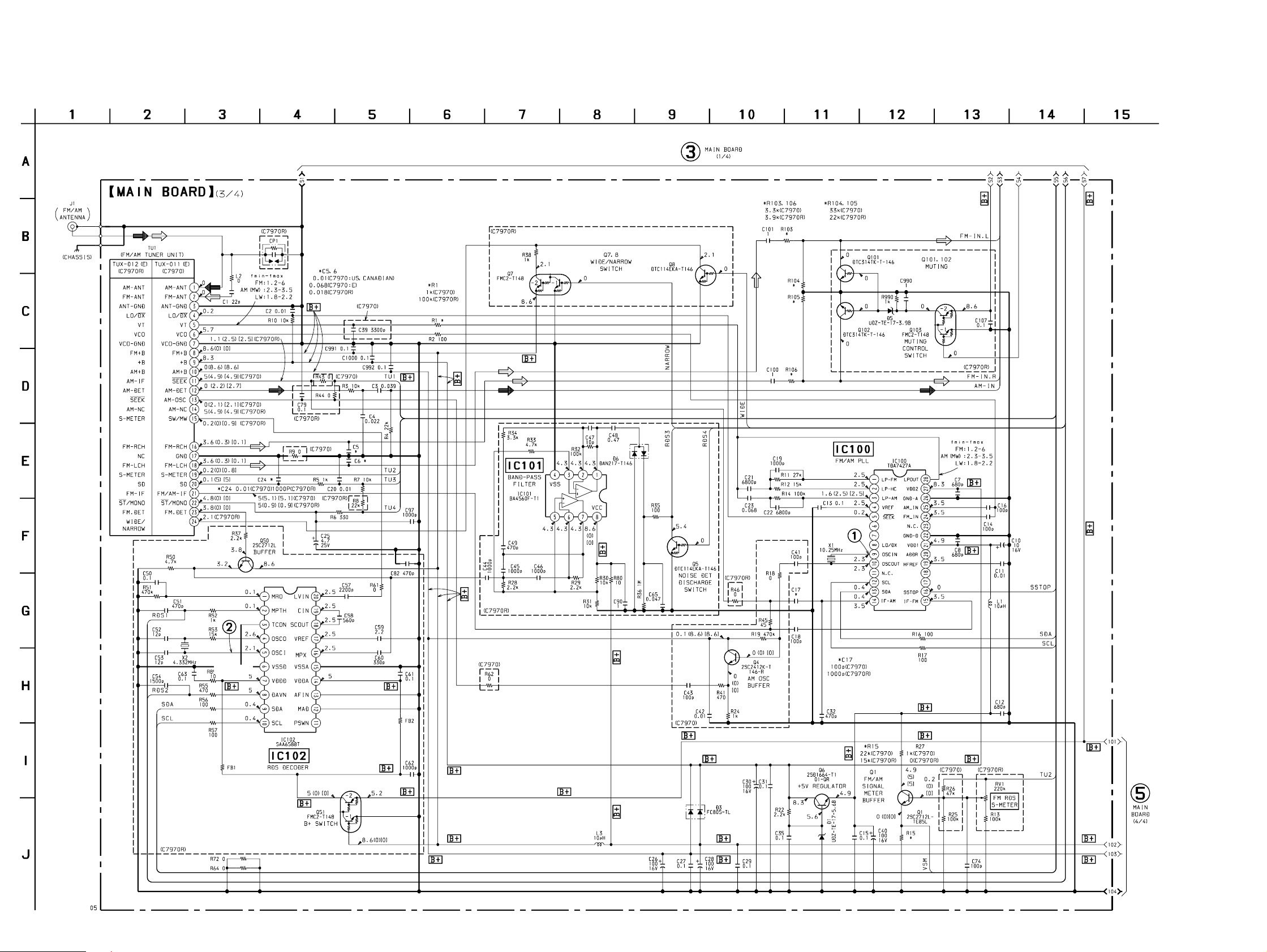
4-15. SCHEMATIC DIAGRAM – MAIN Board (3/4) – • See page 67 for Waveforms. • See page 65 for IC Block Diagrams.
• Voltages and wavefor ms are dc with respect to ground
under no-signal (detuned) conditions.
no mark : FM
( ) : AM (MW)
[]: LW
(Page 48)
– 51 – – 52 –
(Page 53)
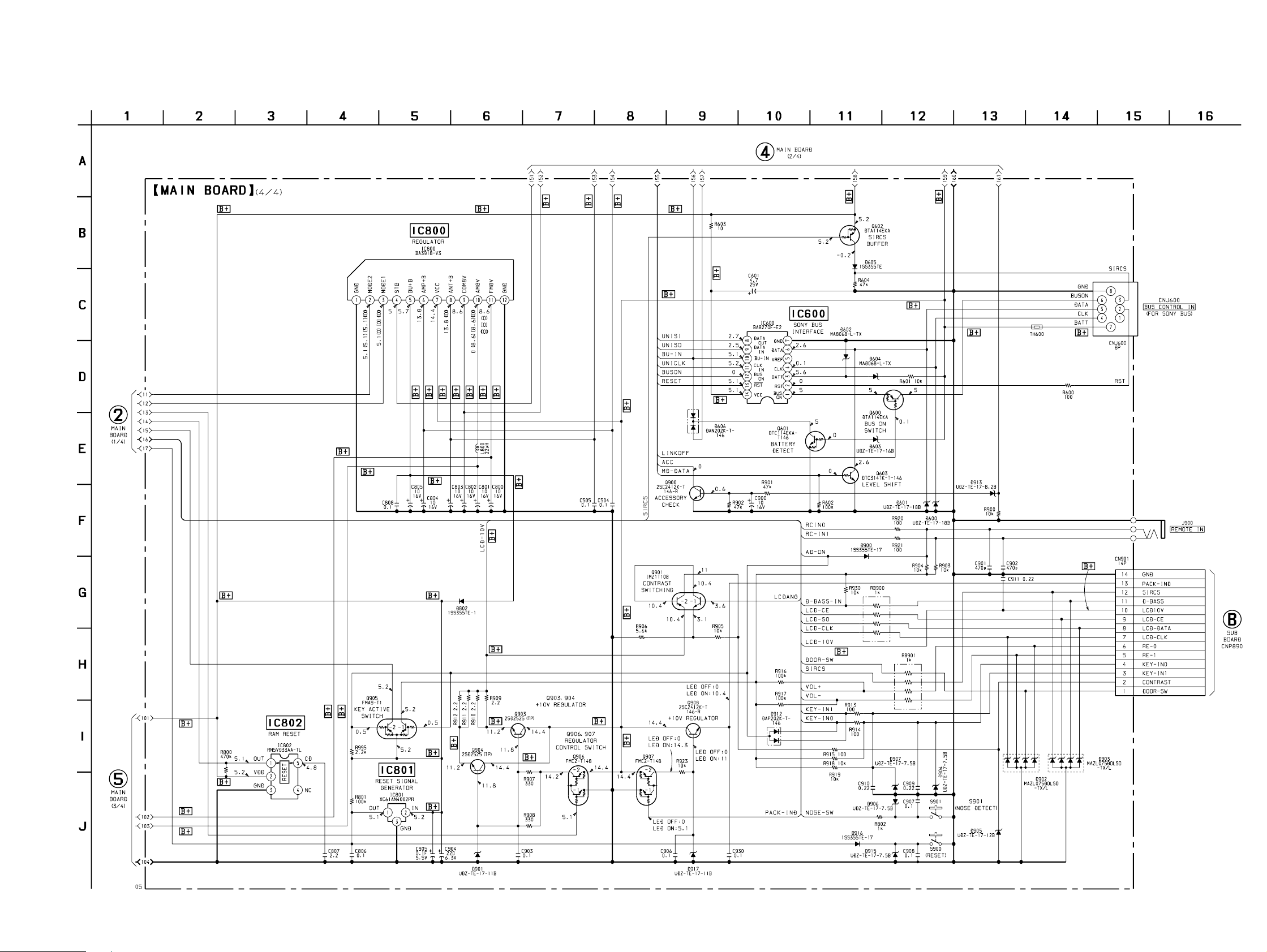
4-16. SCHEMATIC DIAGRAM – MAIN Board (4/4) – • See page 66 for IC Block Diagrams.
• Voltages are dc with respect to ground under no-signal
(detuned) conditions.
no mark : FM
( ) : AM (MW)
[]: LW
〈〈 〉〉 : MD PLAY
(Page 49)
MDX-C7970/C7970R
(Page 48)
(Page 61)
(Page 52)
– 53 – – 54 –
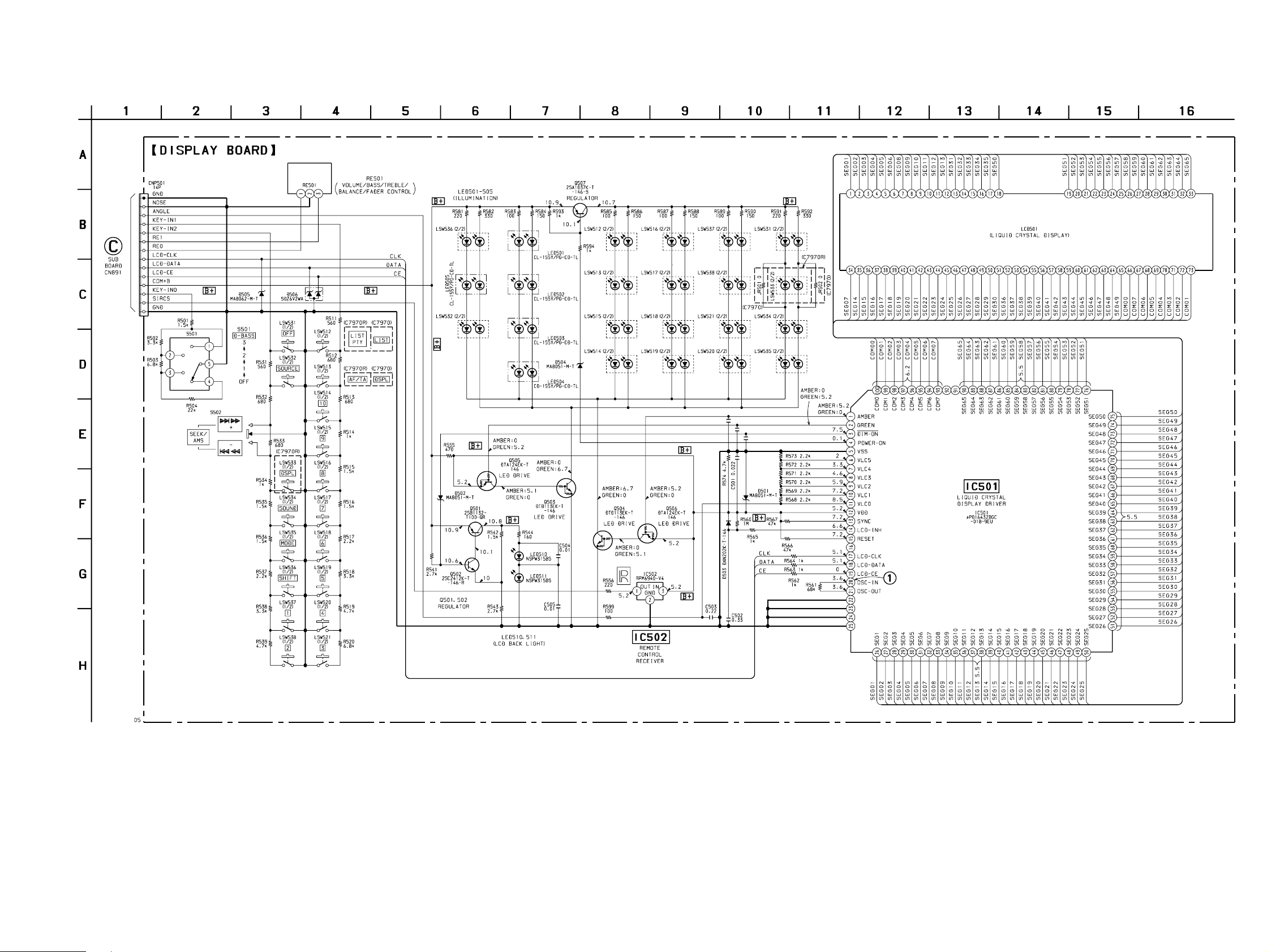
4-18. SCHEMATIC DIAGRAM – DISPLAY Board – • See page 68 for Waveform.
(Page
61)
MDX-C7970/C7970R
• Voltages and waveforms are dc with respect to ground
under no-signal (detuned) conditions.
no mark : FM
– 57 – – 58 –
 Loading...