

Sony MDS-B5, MDS-503, MDS-B6P User Manual

MD RECORDER
MDS-B5
OPERATION MANUAL
1st Edition (Revised 1)
Serial No. 800001 and Higher (UC)
Serial No. 600001 and Higher (CED)
[English]
For the customers in U.S.A.
Owner’s Record
The model and serial numbers are located on the top of the
unit. Record the serial number in the space provided below.
Refer to them whenever you call upon your Sony dealer
regarding this product.
Model No. MDS-B5 Serial No.
WARNING
To prevent fire or shock hazard, do not
expose the unit to rain or moisture.
INFORMATION
This equipment has been tested and found to comply with
the limits for a Class A digital device, pursuant to Part 15 of
the FCC Rules. These limits are designed to provide
reasonable protection against harmful interference when the
equipment is operated in a commercial environment. This
equipment generates, uses, and can radiate radio frequency
energy and, if not installed and used in accordance with the
instruction manual, may cause harmful interference to radio
communications. Operation of this equipment in a
residential area is likely to cause harmful interference in
which case the user will be required to correct the
interference at his own expense.
You are cautioned that any changes or modifications not
expressly approved in this manual could void your authority
to operate this equipment.
The shielded interface cable recommended in this manual
must be used with this equipment in order to comply with
the limits for a digital device pursuant to Subpart B of Part
15 of FCC Rules.
CAUTION
As the laser beam used in this MD deck is harmful to the
eyes, do not attempt to disassemble the cabinet. Refer
servicing to qualified personnel only.
This symbol is intended to alert the
user to the presence of uninsulated
“dangerous voltage” within the
product’s enclosure that may be of
sufficient magnitude to constitute a risk
of electric shock to persons.
This symbol is intended to alert the
user to the presence of important
operating and maintenance (servicing)
instructions in the literature
accompanying the appliance.
CAUTION
TO PREVENT ELECTRIC SHOCK, DO NOT USE THIS
POLARIZED AC PLUG WITH AN EXTENSION CORD,
RECEPTACLE OR OTHER OUTLET UNLESS THE
BLADES CAN BE FULLY INSERTED TO PREVENT
BLADE EXPOSURE.
Notes on shipping of the unit
When shipping the unit, make sure the following
conditions have been met:
• The unit is in shipping mode.
• The unit is packed in its original carton.
Please note that if these conditions are not met, any
damage that occurs to the unit during transport will not be
covered by the service warranty.

The following caution label is located inside the unit.
This appliance is classified as a
CLASS 1 LASER product.
The CLASS 1 LASER PRODUCT
MARKING is located on the side
of the unit.
For customers in Canada
This Class A digital apparatus meets all requirements of
the Canadian Interference-Causing Equipment
Regulations.
Pour les utilisateurs au Canada
Cet appareil numérique de la classe A respecte toutes les
exigences du Règlement sur le matériel brouilleur du
Canada.
For the customers in the United Kingdom
WARNING
THIS APPARATUS MUST BE EARTHED
IMPORTANT
The wires in this mains lead are coloured in accordance
with the following code:
Green-and-yellow: Earth
Blue: Neutral
Brown: Live
As the colours of the wires in the mains lead of this
apparatus may not correspond with the coloured markings
identifying the terminals in your plug proceed as follows:
The wire which is coloured green-and-yellow must be
connected to the terminal in the plug which is marked by
the letter E or by the safety earth symbol Y or coloured
green or green-and-yellow.
The wire which is coloured blue must be connected to the
terminal which is marked with the letter N or coloured
black.
The wire which is coloured brown must be connected to the
terminal which is marked with the letter L or coloured red.


Table of Contents
Chapter 1
Overview
Chapter 2
Function of Parts and
Controls
Chapter 3
Preparations
Chapter 4
Recording
1-1 Features ........................................................................................... 1-1
1-1-1 Features of the MiniDisc........................................................ 1-1
1-1-2 Operational Features .............................................................. 1-1
2-1 Front Panel...................................................................................... 2-1
2-2 Rear Panel ....................................................................................... 2-3
2-3 Remote Controller.......................................................................... 2-5
3-1 Precautions...................................................................................... 3-1
3-1-1 Installation Precautions.......................................................... 3-1
3-1-2 Handling Precautions ............................................................. 3-1
3-1-3 Shipping Precautions.............................................................. 3-1
3-2 Connections..................................................................................... 3-2
3-2-1 Precautions............................................................................. 3-2
3-2-2 Basic Connection Examples................................................... 3-2
3-2-3 Connection for Direct ATRAC Data Copying....................... 3-3
3-2-4 Connecting and Setting the Keyboard ................................... 3-4
3-3 Handling MiniDiscs........................................................................ 3-5
3-4 Setting the Analog Input and Output Reference Levels ............. 3-6
4-1 Selecting the Input Signal .............................................................. 4-1
4-2 Recording Procedure ..................................................................... 4-2
4-3 Display Information During Recording ....................................... 4-4
4-4 Adding Disc and Track Titles ....................................................... 4-5
4-5 Procedure of Direct ATRAC Data Copying ................................ 4-6
4-6 Restrictions on Digital Copying .................................................... 4-7
Chapter 5
Playback
(Continued)
5-1 Overview of Playback Procedures ................................................ 5-1
5-2 Playback Procedures...................................................................... 5-2
5-2-1 Playing From the First Track on the MD............................... 5-2
5-2-2 Locating a Specific Point (Search)......................................... 5-2
5-2-3 Playing a Single Track Only .................................................. 5-3
5-2-4 Rehearsal Playback ................................................................ 5-3
5-3 Locating a Track ............................................................................ 5-4
5-3-1 Locating a Specific Track ...................................................... 5-4
5-3-2 Locating the Beginning of a Track (AMS) ............................ 5-4
5-3-3 Preparing the Next Track During Playback ........................... 5-5
5-4 Display Information during Playback.......................................... 5-6
5-5 Playing Tracks Repeatedly ............................................................ 5-7
5-6 Program Play .................................................................................. 5-8
5-7 Playing Tracks in Random Order (Shuffle Play) ...................... 5-10
5-8 Starting Playback Instantly (Multi-Access Function)............... 5-11
5-9 Varying the Playback Speed (Variable-Speed Playback)......... 5-13
Table of Contents 1

Table of Contents
Chapter 6
Editing Functions
Chapter 7
Setup Menu
6-1 Overview of Editing Functions...................................................... 6-1
6-1-1 Types of Editing Functions.................................................... 6-1
6-1-2 RAM Edit and Disc Edit........................................................ 6-1
6-1-3 Track Numbers After Editing Operations.............................. 6-2
6-1-4 Editing Operations During Rehearsal Playback..................... 6-2
6-1-5 Undo function ........................................................................ 6-2
6-2 Erasing Tracks (Erase Function).................................................. 6-3
6-3 Dividing a Recorded Track (Divide Function) ............................ 6-4
6-4 Combining Recorded Tracks (Combine Function)..................... 6-6
6-5 Moving Recorded Tracks (Move Function)................................. 6-7
6-6 Editing Titles................................................................................... 6-8
6-7 Marking the Cue Point ................................................................ 6-10
6-8 Trimming ...................................................................................... 6-12
6-8-1 Head Trimming.................................................................... 6-12
6-8-2 End Trimming...................................................................... 6-14
7-1 The Overview of the Setup Menu ................................................. 7-1
7-2 LevelSync Setting (Track Marking Function)............................. 7-2
7-3 Setting Up for Timer-Activated Function .................................... 7-3
7-4 Setting the Playback Resume Mode.............................................. 7-4
7-5 Setting the RS-232C Interface....................................................... 7-5
7-6 Setting the Auto Cue Function ...................................................... 7-6
7-7 Setting the Rehearsal Playback Function .................................... 7-7
7-8 Setting the EOM Function............................................................. 7-8
7-9 Reading the Hours Meter .............................................................. 7-9
7-10 Disabling the Buttons While Controlling Remotely................. 7-10
Chapter 8
Maintenance
Appendix
8-1 Cleaning and Reset Switch ............................................................. 8-1
8-2 Display Messages ............................................................................. 8-2
Menu Item List ..................................................................................... A-1
Pin Assignments for REMOTE (25P) connector ............................... A-3
RS-232C Protocol ................................................................................. A-5
RS-232C Protocol............................................................................ A-5
Specifications .................................................................................. A-5
Operating Method............................................................................ A-5
List of Commands ......................................................................... A-10
Command Descriptions...................................................................... A-11
Specifications....................................................................................... A-26
Index ........................................................................................................I-1
2 Table of Contents

1-1 Features
Chapter 1 Overview
The MDS-B5 is a MiniDisc deck for professional use
in any kind of broadcasting, announcements, or
program production.
1-1-1 Features of the MiniDisc
ATRAC (Adaptive Transform Acoustic
Coding) data compression technology
By eliminating inaudible sound data to obtain a
compression ratio of 1:5, ATRAC data compression
technology enables the recording of sound information
of almost the same quality and quantity as a CD, but
on a smaller disc.
74 minutes of playback or recording
A single MD can be used to play back or record up to
74 minutes of sound information. In monoaural mode,
you can record and play back up to 148 minutes.
Direct track access
You can use the supplied wire-connected remote
controller or an IBM keyboard (not supplied) to
directly access any of the MD’s 255 tracks without the
long cueing time required for tape.
Various playback functions
Text entry
You can use the supplied wire-connected remote
controller or an IBM keyboard to enter titles for
recorded discs and tracks. Title data, which can total
1,792 characters per disc, appear in the display
window during playback.
Durability
Because MDs use a non-contact system like compact
discs, they are superior to cassette tape in durability.
1-1-2 Operational Features
Direct ATRAC data copy function
Multiple MDS-B5 decks can be daisy chained through
the DIRECT DUPLICATION LINK connectors,
allowing ATRAC compression data to be copied about
four times faster than normal dubbing speed. Up to ten
MDS-B5 decks can be daisy chained. When using this
function, the character information on the disc will
also be copied.
Instant playback function
The MDS-B5 can store the first part of up to 10
selected tracks into memory in order to begin instant
playback.
Chapter 1 Overview
The MDS-B5’s various playback functions include
repeat playback, programmed playback, and random
playback. You can also vary the playback speed
between ±12.5% of the normal speed.
Multiple editing functions
The MDS-B5’s editing functions allow you to divide,
combine, and move tracks on the MD. You can use
the rehearsal function to precisely position edit points
on a track as you monitor the sound.
Unlike tracks on an analog cassette or DAT tape,
specific MD tracks or an entire MD can be erased
instantly.
Two cueing modes
You can use the A.MODE button to select the
following two cueing modes.
AUTO PAUSE mode
AUTO PAUSE mode pauses the MD deck at the
beginning of a track, then starts playback when you
press the PLAY/PAUSE button. Use this mode to precue tracks during on-air broadcasting with multiple
MD decks.
Chapter 1 Overview 1-1

1-1 Features
AUTO CUE mode
AUTO CUE mode pauses the MD deck when it detects
Chapter 1 Overview
a rise in the audio signal following the inaudible
portion before the start of a track. This mode is good
for playing special sound effects in theater
productions, etc.
NEXT TRACK SELECT function
During single-deck operations, you can specify the
next track to be played as you are playing another one.
Single track play
No matter what the cueing mode may be, you can
always play back single tracks. After playing a single
track, the deck stops rather than pauses, thus
preventing the mistaken playback of another track.
Playback display variations
RAM Edit function
You can do temporary editing, such as dividing,
combining, and moving the tracks on the MD, without
overwriting the TOC information. The results of the
RAM edit function will be lost when the MiniDisc is
ejected. You can use the RAM edit function on premastered MDs.
Program Play information recording
You can record the playback order of up to 25 tracks
for the Program Play function in the TOC on
recordable discs, even when the “PROGRAM”
indication does not appear in the display.
UNDO function
You can undo the last editing operation (e.g., when
you have mistakenly erased a track).
The MDS-B5 displays track information (playing time,
track title, etc.) for the current and the next tracks that
have been selected for playback. By pressing the
DISPLAY button, you can display the following track
information:
•Remaining playing time and title of the current track
•Elapsed time and title of the current track
•Remaining playing time of the current track and a list
of programmed tracks during Program Play or Instant
Playback.
•Playing time and title of the next track
Rehearsal function
You can play back a portion of a track repeatedly in
order to precisely determine points for cueing or track
division. You can also use the Setup menu to specify
the length of the portion to be repeated and the interval
between the end of one repeat and the start of another.
LevelSync function
The LevelSync function adds a track number whenever
the audio signal rises above a threshold level during
recording (except for digital recording from a CD or
MD).
You can use the Setup menu to define the length of an
inaudible portion and the threshold level. You can
also specify a margin between the threshold point and
the writing of the track number.
End-of-message (EOM) function
This function outputs a tally signal from the
REMOTE(25P) connector before the end of a track or
the disc.
You can use the Setup menu to specify how far in
advance of the end the tally signal is output.
Cue point function
1-2 Chapter 1 Overview
This function outputs a tally signal from the
REMOTE(25P) connector whenever a cue point is
detected during playback. Up to 255 cue points can be
marked per disc.

Track trimming function
RS-232C interface
You can temporarily modify the starting and ending
points of a track. The head trimming edit allows you
to specify the starting point in accordance to the audio
rising point.
Digital time meter
The digital time meter displays the accumulated laser
diode recording time and spindle motor operation time.
Easy menu operations
The editing and setting operations on the MDS-B5 are
done using two types of menus: the Edit menu and the
Setup menu. Menu operations are easily done using
the AMS control, turning it to select items and
pressing it to select the setting.
Remote Controller
The supplied remote controller allows you to enter
titles and other text information easily.
The MDS-B5 can be controlled by a personal
computer or other external equipment connected to the
deck through the RS-232C interface.
Rack mounting compatibility
Two MDS-B5 decks can be mounted side by side in a
standard 19-inch EIA rack.
TOC data back-up function
If power to the MDS-B5 is suddenly cut off during
recording or editing, edited TOC data in the MDSB5’s RAM will be saved and maintained by an internal
back-up power supply for up to three days.
Notes
•TOC data may be lost if the power is cut at the
moment of the beginning or the end of recording or
editing operation.
•Due to the limited capacity of the RAM, cue points
and trimming point specifications are not saved.
Chapter 1 Overview
Keyboard operations
You can use the supplied keyboard template on any
IBM keyboard to operate the MDS-B5.
Remote control function
The MDS-B5 can be controlled by external control
signals input to the REMOTE(25P) connector on the
rear panel. You can select any of four pin assignments
for the REMOTE(25P) connector, depending on the
application.
When the deck is controlled by external control
signals, you can disable the operation buttons and
controls on the front panel by using the Kill Local
function.
Error check function
The MDS-B5 can play back a disc at four times
normal playback speed, allowing you to quickly verify
the integrity of tracks before a broadcast.
Chapter 1 Overview 1-3

2-1 Front Panel
Chapter 2 Function of Parts and Controls
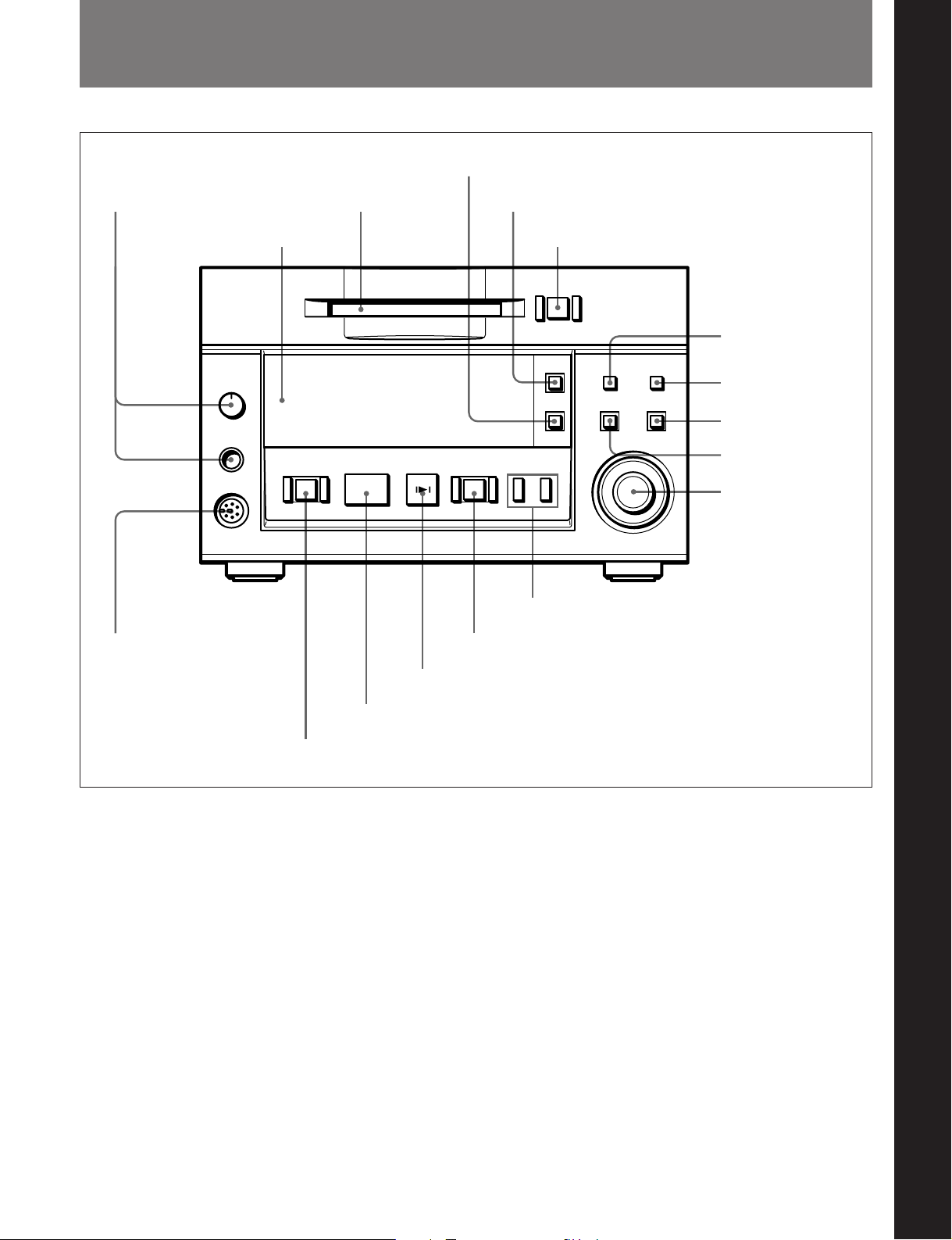
4 SINGLE button
1 PHONES jack and volume control
2 Display
window
!¶ KEY BOARD connector
3 Disc
compartment
p(P
5 A.MODE button
0)
r
!™ Search buttons
!£ REC button
6 EJECT button
=+
Chapter 2 Function of Parts and Controls
7 DISPLAY button
8 REHEARSAL button
9 ENTER/YES button
0 EDIT/NO button
!¡ AMS control
!¢ CUE/STDBY button
!∞ PLAY/PAUSE button
!§ STOP button
1 PHONES jack and volume control
Connects headphones. Use the volume control to
adjust the sound level of the PHONES jack.
2 Display window
Indicates the current MD deck operating status. While
the deck is stopped, the disc title, total track number,
and total recorded time are displayed. During
playback, the track title and time information of the
current track or the next track are displayed. When
using a menu, the menu number and menu item are
displayed.
3 Disc compartment
Automatically loads an inserted disc.
4 SINGLE button
Press to play only one track. “1” appears in the
display window.
5 A.MODE button
Selects the cueing mode. The following are selected in
sequential order each time you press this button.
OFF: The cueing function is disabled. Playback
starts when you press the PLAY/PAUSE button or
select a track using the AMS control.
A.PAUSE: When you press the PLAY/PAUSE
button or select a track using the AMS control, the
MD deck locates the beginning of the track and
pauses. Playback starts when you press the
PLAY/PAUSE button.
A.CUE: When you press the PLAY/PAUSE button
or select a track using the AMS control, the MD
deck pauses whenever the audio signal rises above
a specified threshold level. Playback starts when
you press the PLAY/PAUSE button.
Chapter 2 Function of Parts and Controls 2-1

2-1 Front Panel
6 EJECT button
Press to eject the disc from the disc compartment.
7 DISPLAY button
During playback, press this button to select the
following display contents:
Chapter 2 Function of Parts and Controls
•Remaining playing time and title of the current track
•Elapsed time and title of the current track
•Remaining playing time of the current track and the
Program Play list during Program Play or the Instant
Playback function
•Playing time and title of the next track
8 REHEARSAL button
Press to play a portion of a track repeatedly. If you
press this button during playback, the portion starting
from that point is repeated. If you press the button
while the deck is stopped, the beginning of the first
track on the disc or the selected track is repeated.
During rehearsal playing, you can move the repeated
portion forward or backward by turning the AMS
control. Pressing the 0 or ) button changes the
unit for adjusting the start of Rehearsal Play.
After confirming the cue point or editing point using
the rehearsal function, press the CUE STDBY button
to pause the deck at the position where the rehearsal
started or press EDIT/NO button to execute an editing
function.
9 ENTER/YES button
Press to execute an editing function.
You can also execute editing functions by pressing the
AMS control.
!£ REC (recording) button
Press for recording standby (recording pause). To start
recording, press the PLAY/PAUSE button. The REC
button lights when recording is paused or taking place.
!¢ CUE/STDBY (standby) button
Press to return to the position where you last pressed
the PLAY/PAUSE button. After finding the position,
the MD deck enters playback pause. Use this button to
check or return to a cueing position.
!∞ PLAY/PAUSE button
Press to start playback or recording.
Press during playback to temporarily pause the MD
deck; press again to cancel pause.
The PLAY/PAUSE button lights during playback or
recording. It flashes while the MD deck is in playback
pause or recording pause.
!§ STOP button
Press to stop playback or recording.
!¶ KEYBOARD connector
Connects any IBM keyboard for control of the MD
deck using the supplied keyboard template.
This connector has a cap for protection. Remove the
cap only when connecting a keyboard.
Note
While using the keyboard, turning the MD deck off,
then turning it on again quickly may cause the
keyboard to malfunction. If this occurs, unplug the
keyboard cord and plug it again.
0 EDIT/NO button
Press to display the Edit menu or cancel an editing
function.
!¡ AMS control
Turn to locate the beginning of a track.
When using the Edit menu or the Setup menu, turn this
control to select the menu item and press it to select
the setting.
!™ Search buttons
0: Hold down this button during playback to scan
backward while monitoring the sound.
): Hold down this button during playback to scan
forward while monitoring the sound.
2-2 Chapter 2 Function of Parts and Controls
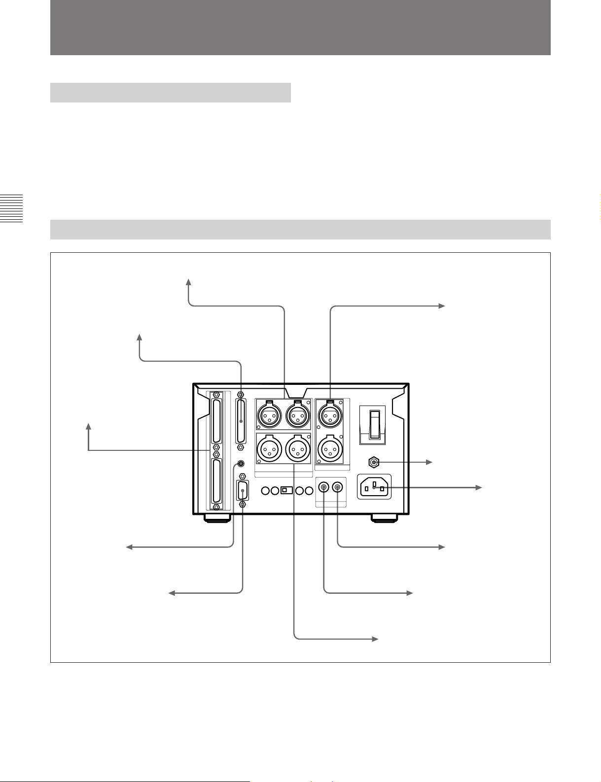
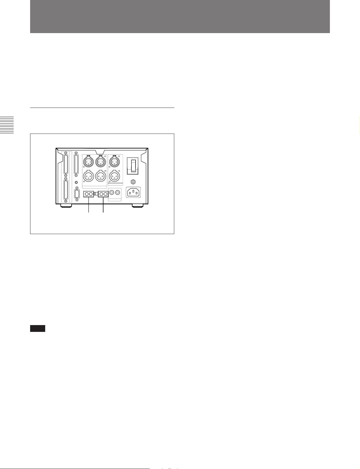
2-2 Rear Panel
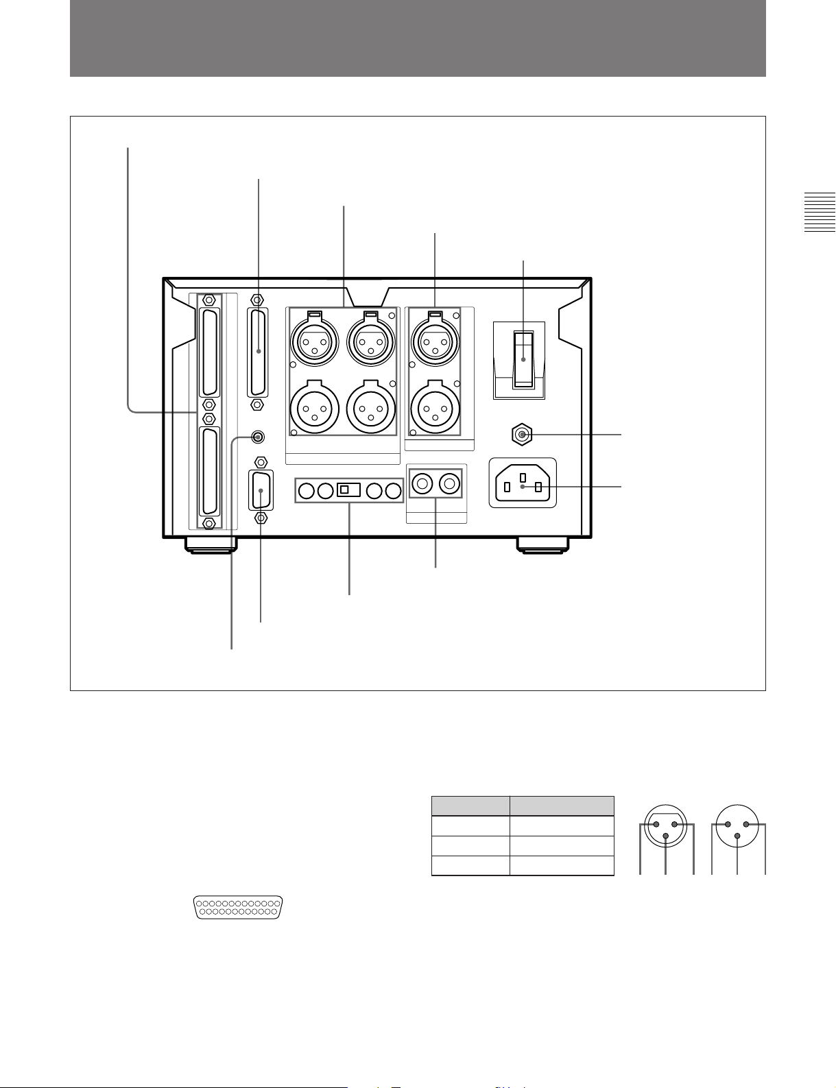
1 DIRECT DUPLICATION LINK connector
2 REMOTE(25P) connector
3 ANALOG IN/OUT connectors
4 AES/EBU IN/OUT connectors
5 POWER switch
8 IEC(958) IN/OUT connectors
9 PLAYBACK/RECORD level controls and MODE switch
Chapter 2 Function of Parts and Controls
6 Ground connector
7 AC IN connector
0 RS-232C connector
!¡ REMOTE connector
1 DIRECT DUPLICATION LINK connector
Used for daisy chaining multiple MDS-B5 decks for
copying ATRAC compression data at the maximum of
about four times the normal recording rate. You can
copy the same data simultaneously on up to ten MDSB5 decks.
2 REMOTE (25P) connector
Connects to external equipment for remote control.
13 1
25 14
You can choose any of four pin assignments,
depending on the purpose.
See “Pin assignments for REMOTE (25P) connector” on
page A-3.
3 ANALOG IN/OUT connectors (XLR-type, 3-pin)
Input and output a two channels of analog audio
signals.
Pin assignment
Pin No. Signal
1 GND
2 HOT
3 COLD
23 1
OUTIN
13 2
4 AES/EBU IN/OUT connector (XLR-type)
Input and output two channels of digital audio signals
in AES/EBU format.
5POWER switch
Press to turn on the MD deck. Press again to turn the
MD deck off.
Chapter 2 Function of Parts and Controls 2-3

2-1 Front Panel
2-2 Rear Panel
6 Ground connector
Connects directly to ground.
7 AC IN connector
Connects to an AC outlet with the supplied AC power
cord.
Chapter 2 Function of Parts and Controls
8 IEC(958) IN/OUT connector (RCA-type, phono)
Inputs digital audio signals for professional use
(IEC958-TYPE1) or consumer use (IEC958-TYPE2).
Outputs digital audio signals for consumer use
(IEC958-TYPE2).
9 PLAYBACK/RECORD level controls and
MODE switch
Adjust the analog input and output reference level
during recording or playback. Adjust the level of each
channel (CH-1(L)/CH-2(R)) by turning the control
with a flat screwdriver.
MODE switch
Selects monaural or stereo mode for the analog input/
output signal.
When MONO is selected during playback, the signals
of channel 1 and 2 are mixed and lowered to below –6
dB, then output from ANALOG OUT CH-1(L) and
CH-2(R).
When MONO is selected during recording, the signals
from ANALOG IN CH-1(L) and ANALOG IN CH2(R) are mixed and lowered to below –6 dB, then
recorded from both channels. The MODE switch just
mixes the input and output signals and has nothing to
do with the monoaural recording mode based on the
MiniDisc format.
0 RS-232C connector
15
69
You can use a personal computer connected to the
MDS-B5’s RS-232C connector to control the MDS-B5
including following operations:
•Button operations
PLAY/PAUSE, STOP, REC, EJECT, PREVIOUS,
NEXT, CUE STDBY
•Direct track access
•Selecting menu functions
Selecting the timing for the end-of-message (EOM)
tally signal output, setting the AUTO PAUSE and
AUTO CUE functions, setting the LevelSync
function, and selecting the input signal
•Displaying time and character data and messages on
an external computer
See “RS-232C Protocol” on page A-5 for details.
!¡ REMOTE connector
Connects the supplied remote controller.
For the monoaural recording mode, see “To record in
monoaural mode” on page 4-2.
Note
If a signal is recorded from only one ANALOG IN
connector in monaural mode, the recording level will
be –6 dB lower than that recorded in stereo mode. In
this case, use the PLAYBACK/RECORD level control
to bring the recording level up to that of stereo mode.
2-4 Chapter 2 Function of Parts and Controls
2-3 Remote Controller
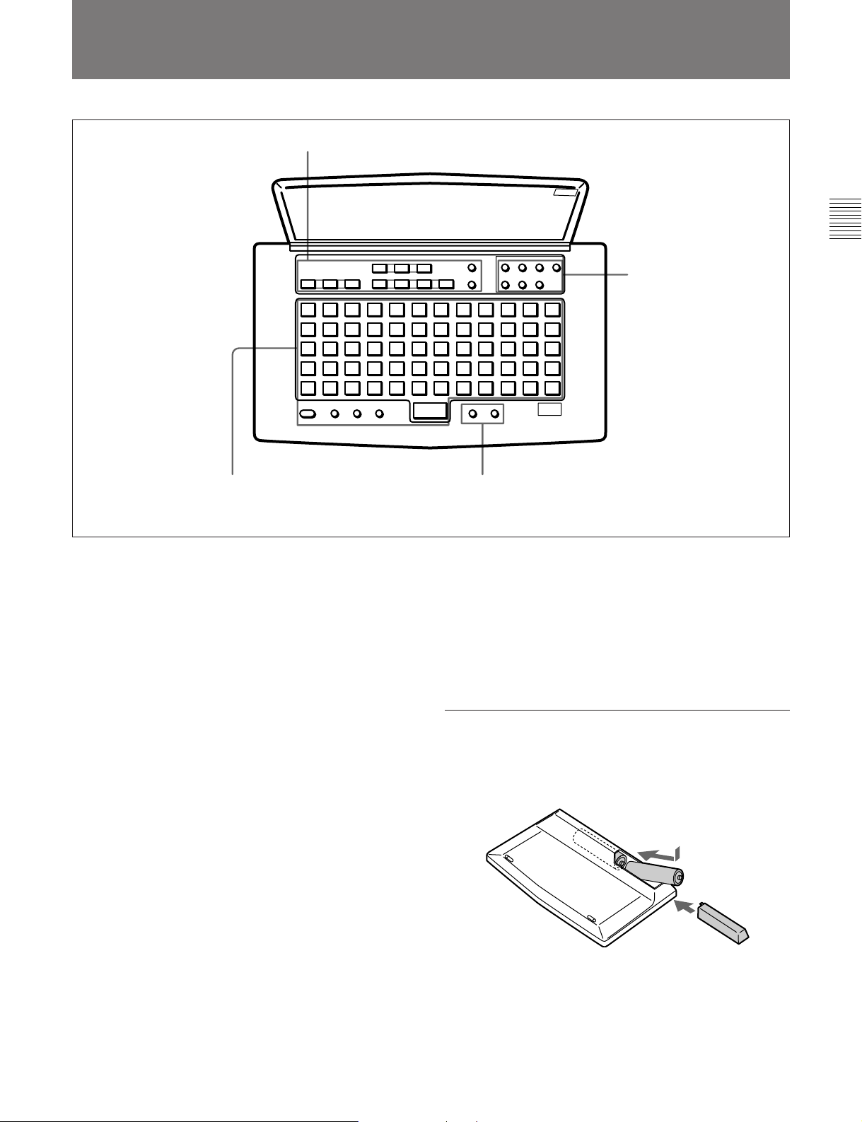
1 MD control buttons
Chapter 2 Function of Parts and Controls
2 Edit operation buttons
4 Title entry buttons
1 MD control buttons
A.MODE (Cueing mode)
SINGLE (Single-track playback)
REHEARSAL (Rehearsal playback)
^ (play/pause)
e (cueing/standby)
p (stop)
= (previous)
+ (next)
0 (rewind)
) (fast forward)
r (record)
T.REC (Time-Machine record)
2 Edit operation buttons
ERASE (erasing tracks)
DIVIDE (dividing tracks)
COMBINE (combining tracks)
MOVE (moving tracks)
UNDO (cancelling the last operation)
ENTER (ENTER/YES button)
CANCEL (EDIT/NO button)
3 Display buttons
SCROLL (viewing the rest of the title during
playback)
DISPLAY (changing the display mode)
3 Display buttons
4 Title entry buttons
NAME (entering title entry mode)
CAPS (uppercase letters, numbers, symbols)*
SML (lowercase letters, numbers, symbols)*
π (unmarked button; space button)
character/numeric buttons (60 buttons)
* The CAPS and SML buttons light up when activated.
Installing batteries in the remote controller
Insert two R6 (size-AA) batteries, making sure the
batteries are aligned with the + and – marks for proper
polarity.
Insert } end first.
}
]
When to replace batteries
The service life of the batteries are for about 6 months.
Replace the batteries when they run down and the
remote controller cannot control the MD deck any
more.
Chapter 2 Function of Parts and Controls 2-5


3-1 Precautions
Chapter 3 Preparations
3-1-1 Installation Precautions
Install the MD deck on a flat surface in a temperaturecontrolled room. Avoid using or storing the MD deck
at a location that is:
•extremely hot or cold.
•damp.
•subject to severe vibrations.
•subject to strong magnetic fields.
•subject to many hours of direct sunlight or close to
heating equipment.
3-1-2 Handling Precautions
•Check the MD deck’s operating voltage before you
plug it in. It must be identical with that of your local
power supply.
•If you drop any liquid or metal object inside the MD
deck, immediately stop using it, unplug the power
cord from the socket, and contact Sony service
personnel.
•If the MD deck will be unused for a long time, make
sure to unplug its power cord from the socket. When
unplugging the power cord, grasp it by the plug, not
the cord.
•Do not disassemble the MD deck. The laser light
used in the deck can cause damage to your eyes. If
the MD deck needs to be inspected, contact Sony
service personnel.
If trouble occurs
Should you detect an abnormal noise, smell, or smoke,
immediately turn off the power, unplug the power cord
from the socket, and contact Sony service personnel.
AC power cord
Do not use any power cord other than the one supplied
with the MD deck.
Chapter 3 Preparations
3-1-3 Shipping Precautions
When shipping the MD deck, make sure that the MD
deck is packed in its original carton. If not, any
damage that occurs to the MD deck during transport
will not be covered by the service warranty.
Caution
The use of optical instruments with this product will
increase eye hazard.
Condensation
Bringing in the MD deck from a cold place or turning
on the room heating may cause moisture to condense
on the lens within the MD deck, resulting in abnormal
operation. If this occurs, leave the power on. The
moisture will evaporate within an hour and the MD
deck will function normally again.
If the MD deck does not operate normally after a few
hours, contact Sony service personnel.
Chapter 3 Preparations 3-1
3-2 Connections
3-2 Connections
3-2-1 Precautions
•Turn off all equipment before connecting or
disconnecting any cables.
•Insert all electrical plugs firmly since incomplete
connection may cause noise.
•Use a cord somewhat longer than needed to prevent
the plug from being pulled out when jarred or shaken.
Chapter 3 Preparations
3-2-2 Basic Connection Examples
MDS-B5
To the supplied
remote controller
To an analog mixing console or amplifier
To an external remote controller
Remote signal
Remote signal
Analog audio signals
AES/EBU digital signals
Digital audio signals
To audio/video equipment
for professional use
To ground
AC power cord
To an MD recorder or
other digital recording
device
120 V AC (for the
U.S. and Canada)
220 to 230 V AC
(for the European
countries)
To a personal computer
3-2 Chapter 3 Preparations
Remote signal
Digital audio signals
Analog audio signals
To a CD player, DAT
or MD recorder
To an analog mixing console
or tape recorder
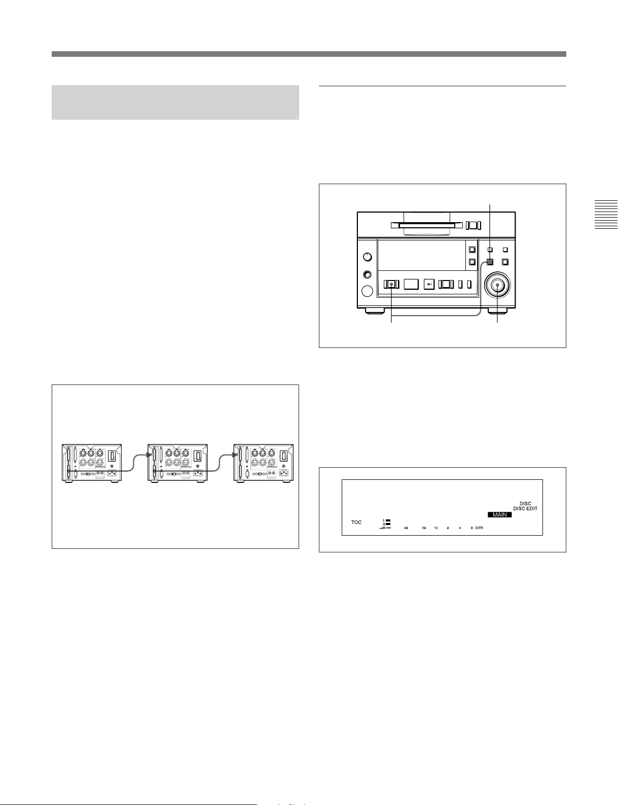
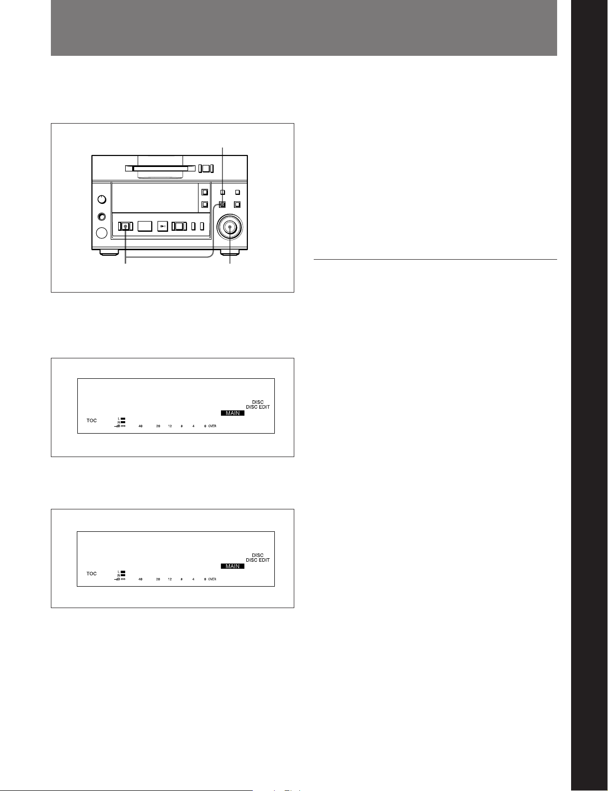
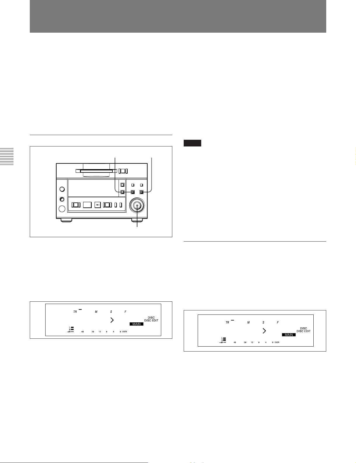
3-2-3 Connection for Direct ATRAC Data Copying
Specifying an MDS-B5 as the main, sub, or
end deck
You can daisy chain multiple MDS-B5 decks through
the DIRECT DUPLICATION LINK connectors to
copy the ATRAC compression data at about four times
the normal recording rate, as well as simultaneously on
up to ten MDS-B5 decks.
To use the direct ATRAC data copy function between
the main deck (which plays the original MD) and the
sub deck (which records the data), connect the
DIRECT DUPLICATION LINE OUT connector on
the main deck to the DIRECT DUPLICATION LINE
IN connector on the sub deck using the specified cable.
To make more than two copies of an MD using the
direct ATRAC data copy function, daisy chain the sub
decks using the DIRECT DUPLICATION LINE OUT
and DIRECT DUPLICATION LINE IN connectors on
each deck and the specified cables. The last sub deck
in the chain must be specified as the “end” deck in the
Setup menu.
The main deck
The sub deck
The end deck
To specify an MDS-B5 as the main, sub, or end deck
when using the direct ATRAC data copy function, do
the following Setup menu procedure.
5
=+
0)
p(P
1
r
2,3,4
1 Press the EDIT/NO button while holding down the
STOP button.
The Setup menu appears in the display window.
2 Turn the AMS control until the menu item F05
(“Dup Main”, “Dup Sub”, “Dup End”, or
“Dup Off”) appears in the window.
Chapter 3 Preparations
OUT
IN
OUT
IN
F05
Dup Main
3 Press the AMS control.
The item flashes and you can change the setting.
4 Turn the AMS control to the item to be set, and
press the AMS control to select it.
When using the direct ATRAC data copy function,
each MDS-B5 in the daisy chain should be
specified as one of the following units:
“Dup Main”: the main deck
“Dup Sub”: a sub deck
“Dup End”: the end deck
“Dup Off”: copy-disabled through the DIRECT
DUPLICATION LINK connector
5 Press the EDIT/NO button to exit from the Setup
menu.
Chapter 3 Preparations 3-3
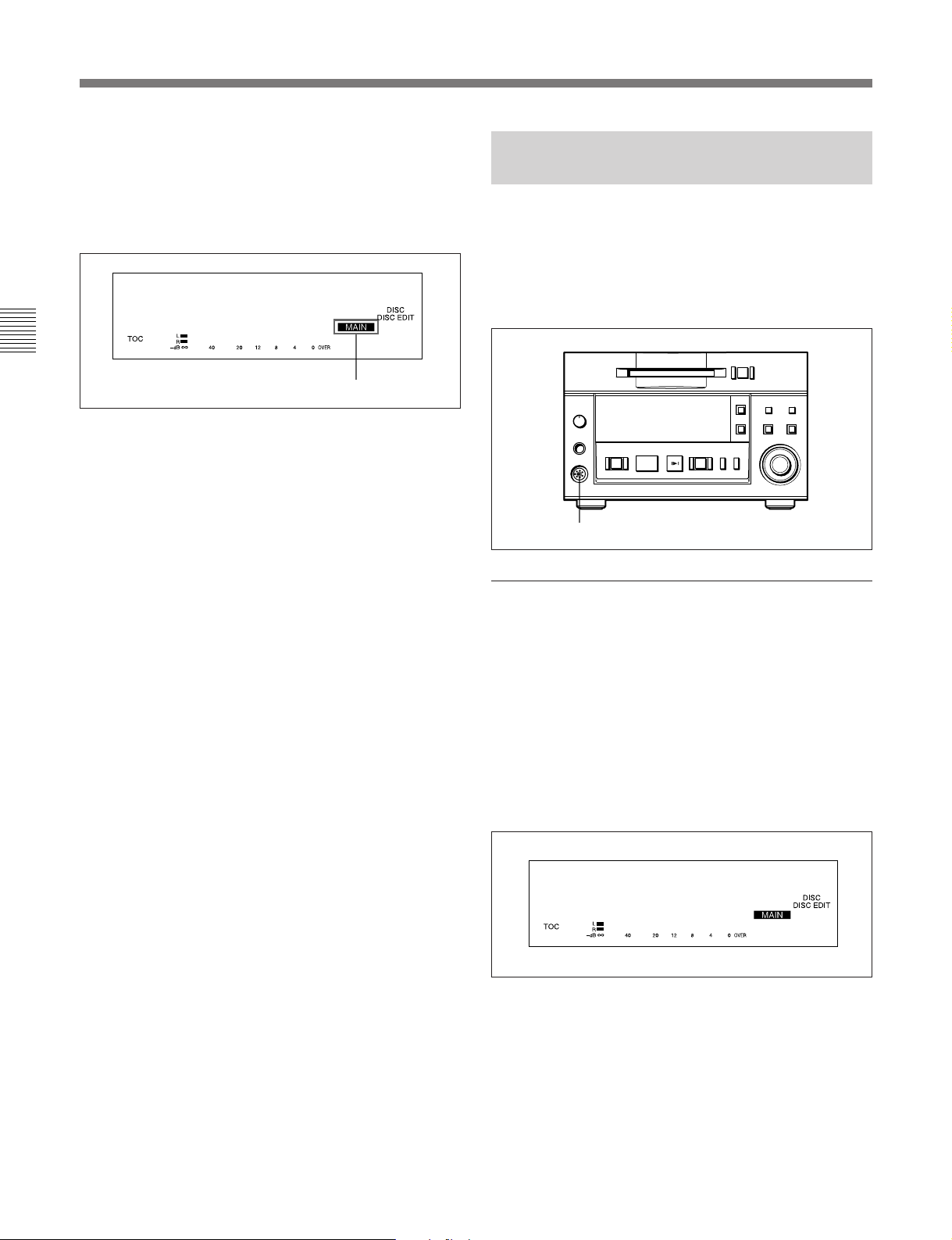
3-2 Connections
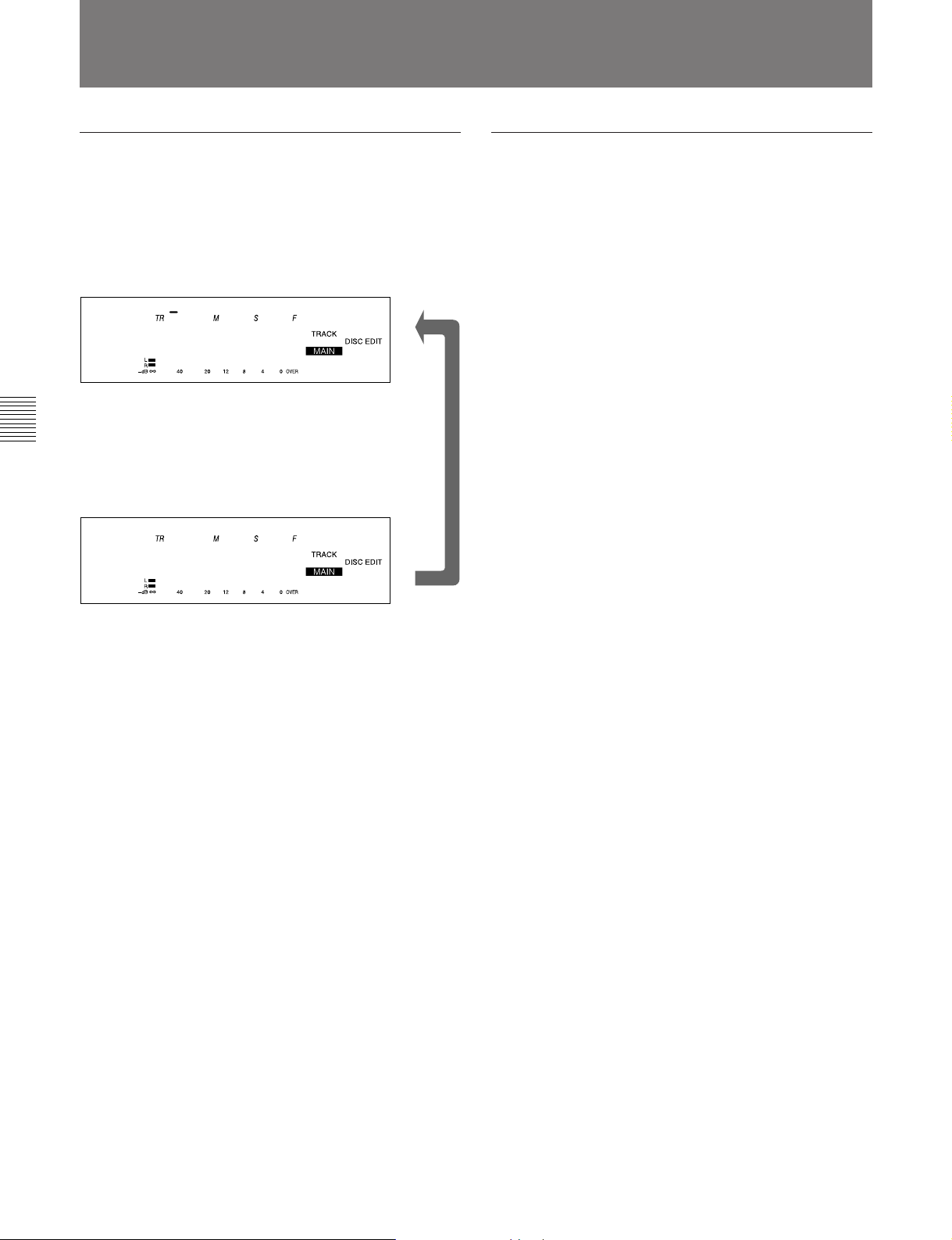
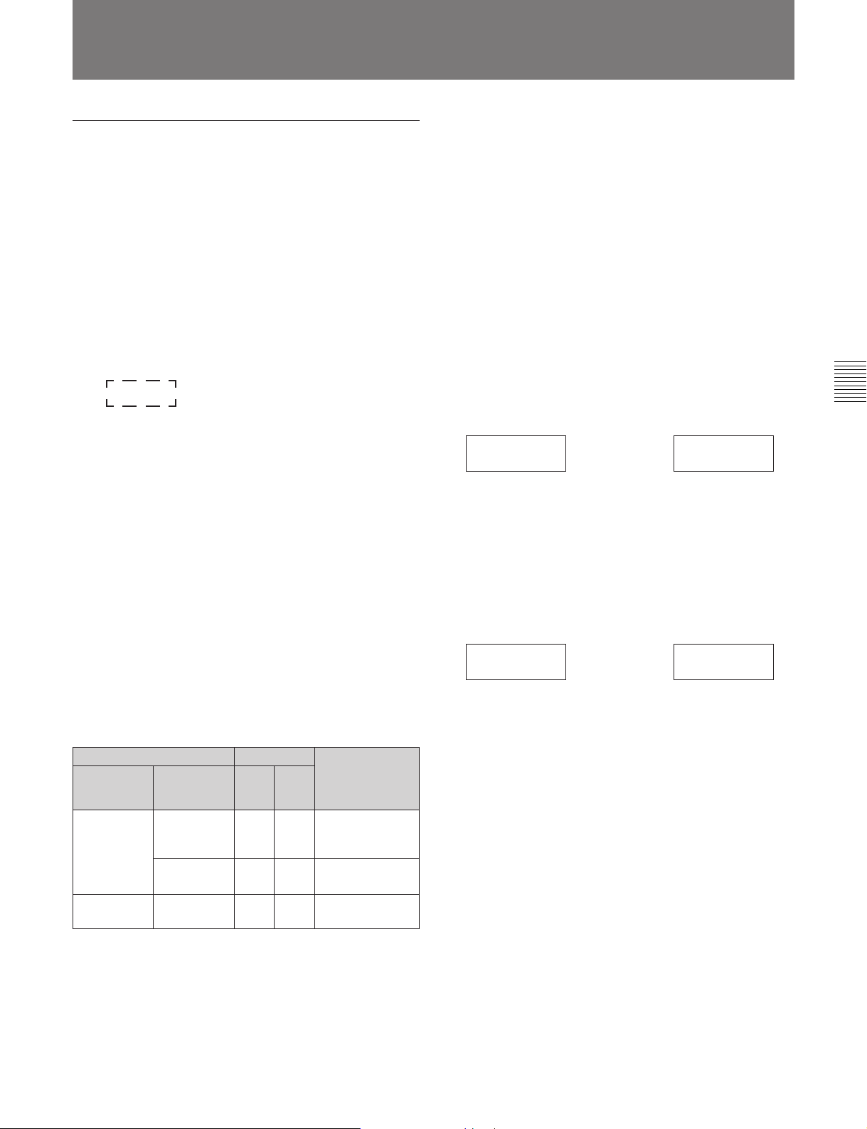
Main/sub deck indication
When you specify an MDS-B5 as a main, sub or end
deck, the status of the deck appears in the display
window. “MAIN” means the main deck and “SUB”
the sub or end deck.
Dup Main
Chapter 3 Preparations
Disabling operation buttons on a sub or end
deck
You can disable the operation buttons on a sub or end
deck to prevent mistaken operations during high-speed
dubbing.
See “7-10 Disabling the Buttons While Controlling
Remotely” on page 7-10 for details.
F05
Main/sub deck indication
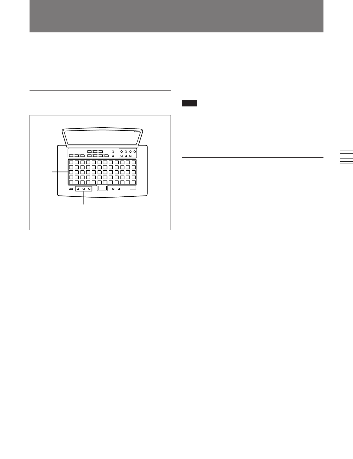
3-2-4 Connecting and Setting the Keyboard
You can use any IBM keyboard to control the MD
deck. The supplied keyboard template has the same
key indications found on the front panel of the deck.
Be sure to remove the cap from the KEY BOARD
connector when connecting a keyboard.
=+
0)
p(P
KEY BOARD connector
Specifying the keyboard type
r
Use the Setup menu to specify the keyboard type.
1 Press the EDIT/NO button while holding down the
STOP button.
The Setup menu appears in the display window.
2 Turn the AMS control to display the menu item
F12 (“KB ENG 101” or “KB JPN 106”) in the
window.
F12
KB ENG 101
3 Press the AMS control.
The indication flashes and you can change the
setting.
4 Turn the AMS control to select either “KB ENG
101” or “KB JPN 106.” Press the AMS control to
select the item.
3-4 Chapter 3 Preparations
5 Press the EDIT/NO button to exit from the Setup
menu.
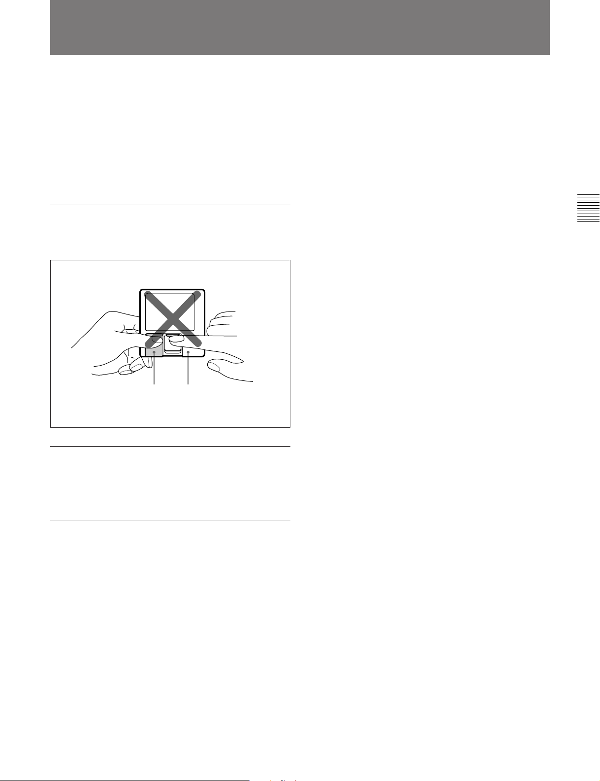
3-3 Handling MiniDiscs
Unlike CDs (Compact Discs), the Mini Disc is encased
within a hard plastic cartridge which allows you to
handle it without fear of dust or fingerprint
contamination. However, a MiniDisc that has been
contaminated or bent may cause the MD player to
malfunction. To prevent damage to the contents of a
disc and to enjoy clear sound permanently, take the
following precautions when handling a MiniDisc.
Do not open the shutter to expose the disc
If you do so, the data on the disc may be damaged.
Chapter 3 Preparations
Shutter Cartridge
Store MiniDiscs in a proper location
Do not place the cartridge where it will be subject to
extremes of sunlight, temperature, moisture or dust.
Cleaning the MiniDisc
Gently wipe the cartridge with a dry soft cloth to
remove dust.
Chapter 3 Preparations 3-5
3-2 Connections
3-4
You can adjust the analog input and output reference
levels during recording or playback within a range of
+8 dB to –12 dB by turning the PLAYBACK and
RECORD level controls on the rear of the MD deck.
The analog input and output reference level is factory
set at +4 dB (at –20 dB from full bit).
Setting the analog input and output
reference levels
Chapter 3 Preparations
Setting the Analog Input and Output Reference Levels
1 2
1 Play back a disc recorded at –20 dB from the full
bit. Adjust the output level of the ANALOG OUT
connectors with the PLAYBACK (CH-1/CH-2)
level controls.
2 Input an audio signal to the ANALOG IN
connectors, and during recording or recording
pause adjust the output level for the ANALOG
OUT connectors with the RECORD (CH-1/CH-2)
level controls.
Note
Adjust the PLAYBACK and RECORD level controls
with a flat screwdriver. Do not use excessive force
when turning the screwdriver or touch the screwdriver
to any part other than the PLAYBACK and RECORD
level controls.
3-6 Chapter 3 Preparations
4-1 Selecting the Input Signal
Chapter 4 Recording
To select the input signal for recording, do the
following Setup menu procedure.
5
=+
0)
p(P
1
r
2,3,4
1 Press the EDIT/NO button while holding down the
STOP button.
The Setup menu appears in the display window.
F26
Kill Almost
2 Turn the AMS control to display the F01: Analog
In menu indication.
4 Turn the AMS control to one of the following
items. Then press the AMS control to select the
item.
“Analog In”: Selects analog input from the
ANALOG IN connectors
“DIN AES/EBU”: Selects the digital input from
the AES/EBU connectors
“DIN Coaxial”: Selects digital input from the
SPDIF IN connectors
5 Press the EDIT/NO button to exit from the Setup
menu.
Recording track numbers automatically
During analog or AES/EBU signal input
Use the LevelSync function to automatically record a
track number whenever the deck detects an inaudible
portion.
To set the LevelSync function, see “7-2 LevelSync Setting
(Track Marking Function)” on page 7-2.
To set the input reference level, see “3-4 Setting the Analog
Input and Output Reference Level” on page 3-6.
During digital input from the IEC(958)
connectors
When recording from a consumer MD deck
*
player
B5 automatically records track numbers according to
the level and U-bit of the digital input signal,
regardless of the LevelSync setting.
, an MDS-B6P, or another MDS-B5, the MDS-
*
, a CD
Chapter 4 Recording
F01
Analog In
3 Press the AMS control.
The indication flashes and you can change the
setting.
..........................................................................................................................................................................................................
*An MD deck or a CD player that is able to output digital
signals with a Q-code added as a U-bit.
Chapter 4 Recording 4-1
4-1 Selecting the Input Signal
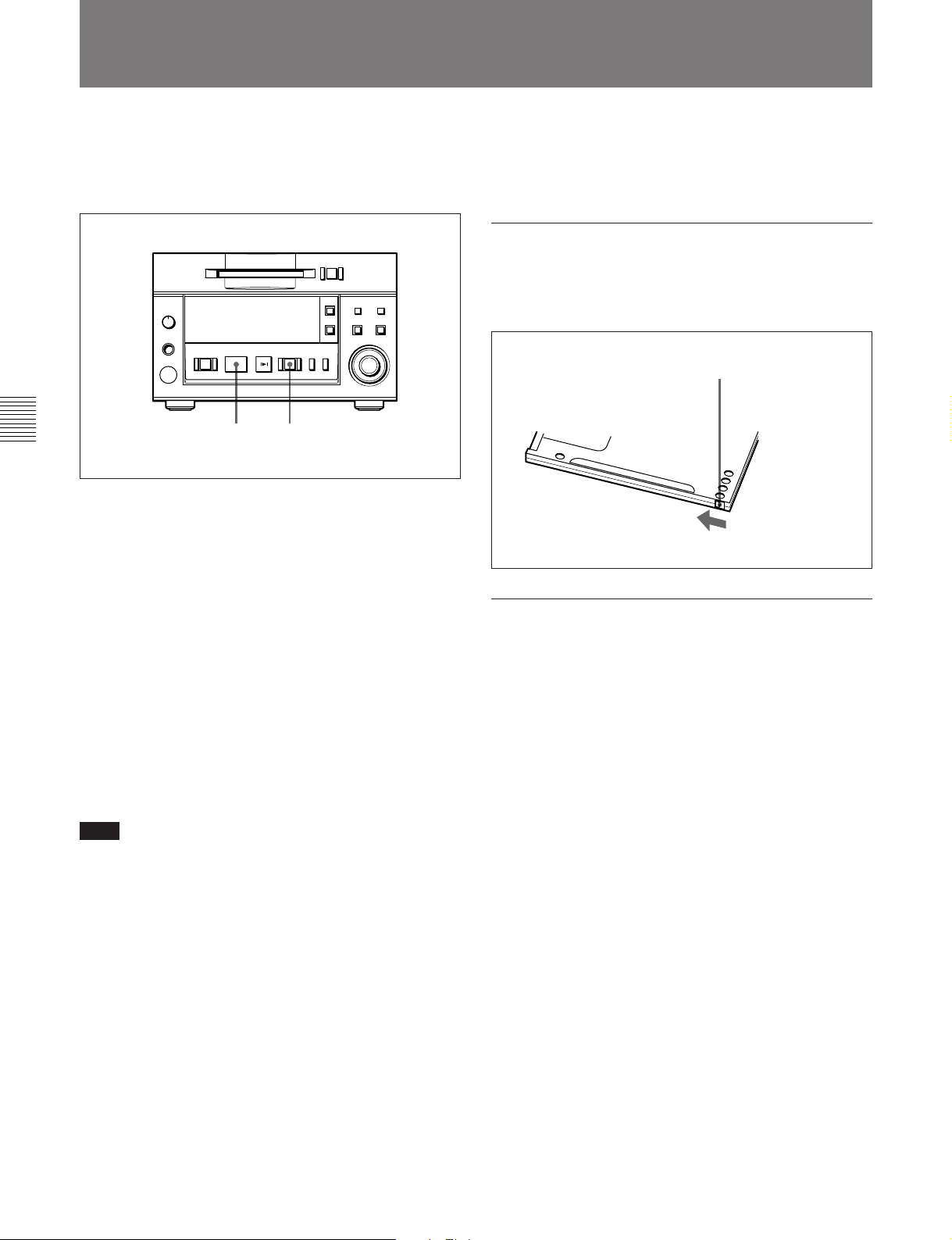
4-2 Recording Procedure
If the inserted disc contains recorded material, the MD
deck will automatically record new material at the end
of the existing material and with a new track number.
Chapter 4 Recording
1 Select the input signal using the Setup menu (see
page 4-1).
2 Press the REC button.
The MD deck enters recording pause. (The REC
button lights up and the PLAY/PAUSE button
flashes.)
3 Press the PLAY/PAUSE button.
Recording starts. (The REC and PLAY/PAUSE
buttons light up.)
p(P
3 2
To eject the disc
Press the STOP button to stop the MD, then press the
EJECT button.
Preventing accidental erasure
Slide the record-protect tab to open the slot. To allow
recording again, slide the tab to close the slot.
=+
0)
r
Rear of the disc
Record-protect tab
Slide the tab in the
direction of arrow.
To record in monoaural mode
The monouaral recording mode allows you to record
about twice as much material on the same amount of
the tape than stereo recording mode. Use the Setup
menu to choose monouaral recording mode.
4 Play the sound source to be recorded.
The number of the track being recorded and
elapsed recording time appear in the display.
Note
When “VariSpeed On” is selected for menu item F07,
it will take about 10 seconds for the MD deck to enter
recording pause.
Recording a track number manually during
recording
Press the REC button at the place you want to add a
track number.
To stop recording
Press the STOP button.
To stop recording temporarily
Press the PLAY/PAUSE button.
To resume recording, press the PLAY/PAUSE button
again.
1 Press the EDIT/NO button while holding down the
STOP button.
The Setup menu appears in the display.
2 Turn the AMS control to select “F04:Stereo Rec.”
3 Press the AMS control.
The indication flashes and the display for setting
the recording mode appears.
4 Turn the AMS control clockwise to display
“F04:Monoral Rec,” then press the AMS control.
The “MONO” indication lights up.
5 Press the EDIT/NO button to exit from the Setup
menu.
4-2 Chapter 4 Recording
About the sampling rate converter
A built-in sampling rate converter automatically
converts the sampling frequency of various digital
sources to the 44.1 kHz sampling rate of the MD deck.
This allows you to record sources such as 32- and 48kHz DAT or satellite broadcasts from the digital input
connectors.
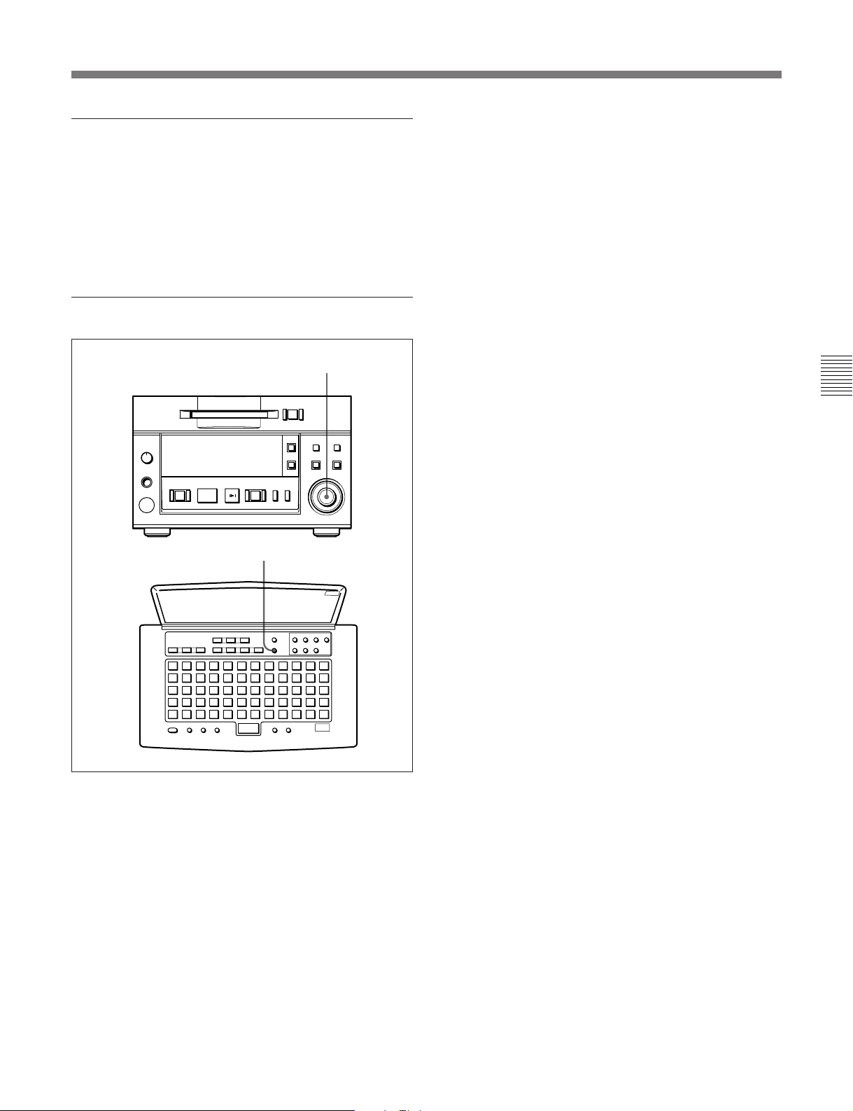
Time-machine recording
AMS control
=+
0)
p(P
r
Chapter 4 Recording
T.REC button
To activate time-machine recording, press the AMS
control on the front panel or the T.REC button on the
remote controller while the deck is in recording pause
mode. Recording takes place starting with the first 6
seconds (maximum) of audio data that has been stored
in the buffer memory in advance.
Chapter 4 Recording 4-3
4-1 Selecting the Input Signal
4-3 Display Information During Recording
Changing the information display during
recording
Each press of the DISPLAY button during recording
changes the information on the display as follows:
Remaining recording time on disc
001 00 25 21
MiniDisc! *
Chapter 4 Recording
Recorded time of the current track
001 00 09 45
MiniDisc! *
v
MD-related limitations
The recording system in your MD deck is radically
different from those used in cassette and DAT decks
and is characterized by the limitations described
below.
“Disc Full” lights up even before the disc has
reached the maximum recording time (60 or
74 minutes)
When 255 tracks have been recorded on the disc,
“Disc Full” lights up regardless of the total recorded
time. More than 255 tracks cannot be recorded on the
disc.
“Disc Full” lights up before the maximum
number of track is reached
Fluctuations in emphasis within tracks are sometimes
interpreted as track intervals, incrementing the track
count.
The total recorded time and the remaining
time on the disc may not equal the maximum
recording time (60 or 74 minutes)
Recording is done in minimum units of 2 seconds
each, no matter how short the material. The contents
recorded may thus be shorter than the maximum
recording capacity. Disc space may also be further
reduced by scratches.
“TOC Reading” indication appears for a long
time
If the inserted recorded disc is brand new, the “TOC
Reading” indication appears on the display longer than
for those that have been used.
Playback of a track of under 4 seconds may
be accompanied by sound dropout at the start
of the next track or mis-operation of the MD
deck.
4-4 Chapter 4 Recording
4-4 Adding Disc and Track Titles
Use the title function to add titles to your own discs
and tracks using the character and numeric buttons on
the remote controller. The maximum number of
characters for all titles on a disc is 1,792.
Adding a disc or track title
3
1,5 2
5 Press the NAME button to record the title on the
disc.
To cancel the title entry process
Press the p button.
Note
If “Protected” appears in the display
The record-protection slot on the disc is open and titles
cannot be written to the disc. To add titles to the disc,
eject the disc and close the slot.
Erasing a disc or track title
Do the procedure below to erase a disc or track title
using the remote controller.
1 Press the NAME button while the deck is playing
or pausing on the track whose title is to be erased.
To erase the disc title, press the button while the
deck is stopped.
Chapter 4 Recording
1 Press the NAME button.
The display changes to title-entry mode.
To add a disc title
Enter a disc title while the MD deck is stopped.
To add a track title
You can add a track title when (1) the MD deck is
playing or recording a track; (2) when the MD
deck is in playback pause, or (3) when the MD
deck is stopped on the track to be entitled.
2 Press either CAPS (uppercase) or SML (lowercase)
to select the type of characters to be entered.
3 Enter the disc or track title with the character and
numeric buttons on the remote controller.
4 Repeat steps 2 and 3 until the entire title appears in
the display.
To change a character entry
Press the 0 or ) button to the character to be
changed. The character will flash. Press the
CANCEL button and repeat the step 2 and 3.
2 Hold down the CANCEL button.
3 Press the ENTER button when the last character of
the title has disappeared and the cursor remains.
Chapter 4 Recording 4-5
4-1 Selecting the Input Signal
4-5 Procedure for Direct ATRAC Data Copying
You can daisy chain multiple MDS-B5 decks and copy
ATRAC compressed data through the DIRECT
DUPLICATION LINK connectors to perform dubbing
at maximum of about four times the normal dubbing
speed. Up to ten MDS-B5 decks can be daisy chained.
Do the procedure for direct ATRAC data copying on
the main deck.
For details on the settings for direct ATRAC data copying
and on specifying an MDS-B5 as a main deck, sub deck, or
end deck, see “3-2-3 Connection for Direct ATRAC Data
Copying” on page 3-3.
To do direct ATRAC data copy
Chapter 4 Recording
p(P
7 Press the AMS control or the PLAY/PAUSE
button.
“Duplicate” flashes and direct ATRAC data
copying starts.
If you selected the “ErrCheckOn” , the sub deck
and end deck automatically begin error checking
after direct ATRAC data copying finishes. When
error checking finishes, “DupComplete!” appears.
8 Press the AMS control or the ENTER/YES button.
The sub and end decks write the TOC information
onto the disc, then exit from the Edit menu.
Notes
ENTER/YES button
3
=+
0)
r
•Direct ATRAC data copying copies TOC-related
character data such as track titles and track numbers.
Note, however, that other TOC data, such as cue
points, trimmimg specifications, program lists, and
multi-access lists, are included only when copying all
tracks onto a blank disc in a sub or end deck.
•Do not press any of the operation buttons until direct
ATRAC data copying finishes and “DupComplete!”
appears on the display. “-Duplicate-” may continue
flashing for a few minutes as the TOC (Table Of
Contents) information is being written, even after the
time information has stopped.
2-8
1 Press the EDIT/NO button.
The Edit menu appears.
2 Turn the AMS control to select “015:Duplicate ?.”
3 Press the AMS control.
The display for selecting the track to be copied
using the direct ATRAC data copy function
appears.
001 00 34 65
Dup Tr1-
4 Turn the AMS control to display the track number
to be copied.
5 Press the AMS control.
“ErrCheckOff” appears.
If you want error checking to be done
automatically after dubbing is completed, turn the
AMS control to select “ErrCheckOn.”
6 Press the AMS control.
“Start: Yes” and “Cancel: No” alternate on the
display.
The sub deck and end deck automatically enter
recording pause, the REC button lights, and the
PLAY/PAUSE button flashes.
To perform error checking only
1 Press the EDIT/NO button.
The Edit menu appears.
2 Turn the AMS control to select “014:Err Check ?” .
3 Press the AMS control.
The display for selecting the track to begin error
checking appears.
001 00 34 65
Check Tr1-
4 Turn the AMS control to select the track number.
5 Press the AMS control.
Error checking starts.
After error checking finishes, the results are
displayed.
6 If any error is detected, press the AMS control
again.
7 Turn the AMS control to display up to ten
positions where error has occurred.
4-6 Chapter 4 Recording
4-6 Restrictions on Digital Copying
Track mode data recorded to a disc during
recording
Track mode data consist of eight bits of information
recorded in the user TOC (Table Of Contents) area on
the disc indicating such disc-related conditions as
copyright status, digital copy restrictions, disc use, and
emphasis data.
Two track mode bits, d2 and d3, which indicate
copyright status and restrictions on digital copies, are
explained below.
Track mode
d1 d2 d3 d4 d5 d6 d7 d8
d2: Copyright status 0: Copyrighted
1: Uncopyrighted
Digital copy generation
d3:
When recording an input signal from the
ANALOG IN or AES/EBU connector or an
IEC958-TYPE1 digital input signal
(for professional use)
The disc will be completely copy-enabled by the Serial
Copy Management System. This status is indicated by
the track mode bit values of d2=1 and d3=1.
0: Original
1:
First-generation copy or later
An MD which contains analog signals recorded on a
consumer MD recorder can used to make a firstgeneration digital copy. No restrictions are placed on
digital copying of MD recordings made on
professional MD recorders, as long as the recording is
made on an MDS-B5. When copying analog signals,
you can use the LevelSync (track marking) function to
record track numbers automatically.
See “7-2 LevelSync Setting (Track Marking Function)” on
page 7-2.
The conditions for digital copying, as determined by
track mode bits d2 and d3, are shown below.
When using two MDS-B5s
MDS-B5 ç MDS-B5
IEC958
TYPE2
X11XXXXX n X11XXXXX Copy-enabled
X00XXXXX n X01XXXXX Copy-enabled
X01XXXXX n X01XXXXX Copy-enabled
When using a consumer MD recorder to make
a copy of a disc recorded on the MDS-B5
Chapter 4 Recording
When recording an IEC958-TYPE2 digital input
signal (for consumer use)
Three types of discs can be produced, depending on
the sub-code information included in the input signal.
Input signal
Category
code
Category
codes other
than that
below
General
ACTUAL A/D
Channel
status bit 2
1
(Uncopyrighted)
0
(Copyrighted)
–00
Track mode bit During digital
d2 d3
1 1 Copy-enabled
01
copying between
two consumer MD
recorders
Copy-disabled
First-generation
copy only
MDS-503 ç MDS-503
IEC958
TYPE2
X11XXXXX n X11XXXXX Copy-enabled
X00XXXXX n X01XXXXX
First-generation copy only
X01XXXXX n Copy-disabled
Chapter 4 Recording 4-7

 Loading...