

Sony KLV-24EX430 Schematic

HISTORY INFORMATION FOR THE FOLLOWING MANUAL:
Version
Date
Subject
SERVICE MANUAL
1 7/2012 1STIssue
LCCT CHASSIS
Segment: P-2L
LCD TV
9-888-135-01

SERVICE MANUAL
LCCT CHASSIS
Segment: P-2L
LCD TV
9-888-135-01

MODEL LIST
MODEL COLOR COMMANDER DEST.
KLV-24EX430 Black RM-GA022 Singapore,
Indonesia, Vietnam
Philippines,
SOGUL,
South Africa, India,
Thailand, Malaysia,
Saudi
MODEL COLOR COMMANDER DEST.
3
S
TABLE OF CONTENTS
S
1. SAFETY NOTES
g
y
g
g
.
g
3-6. IR T
41
g
ging
g
g
g
.
play
y
g
g
g
g
p
g
3. TROUBLE SHOOTING
g
y
g
g
g
g
5-2.Connector Diagram
57
.
.
3-4.Audio Probl
19
g
g
g
g
g
g
p
g
.
…
…
KLV-24 EX430
RM-GA022
ection Tit le Page
1-1. Caution Handlin
1-2. Safet
1-3. Leaka
1-4. How to find a
1-5. WARNING and Caution .......................................... ...... ... ..... ...... ..... ...... ..... ... . 6
1-6. Lead Free Information ............................................... ..... ...... .. ...... ..... ...... ..... ..
1-7. Handlin
1-8. Diassemble Rear Cover 24"……………………………………...………………… 8
1-9. Assemble Rear Cover 24"…………………….………………………………………8
2. SELF DIAGNOSTIC FUNCTI ON
2-1. Overview of Control Buttons ……………........................................ ..... ... ...... ...
2-2. LED Dis
2-3. LED Pattern ............................. ..................................................................... .. 9
2-4. Standb
2-5. Tria
3-1. Troubleshootin
3-2. No Power………….................................................... ..... ... ...... ..... ...... ..... ...... 13
3-2-1. DD-Con…………........................................................................................ 14
3-3. Standb
3-3-1. 2 Ti mes Led Bli n k in
3-3-2. 3 Ti mes Led Bli n k in
3-3-3. 5 Ti mes Led Bli n k in
3-3-4. 6 Ti mes Led Bli n k in
3-4-1. Main Speaker No Sound………….................................................................. .. 20
3-4-2. HP Out No Sound................................................. ... ........................................ 21
3-4-3. Analo
3-4-4. HDMI Audio No Sound………...................................... ..... ...... ..... ...... ..... ... ..... . 23
3-4-5. Analo
3-4-6. USB No Sound………......... ........ ........ . ........ ........ . ........ ........ . ........ ........ . ........ . 25
3-5. Video Problem…………................ ........ ............... ........ ...................... ........ ...... 26
3-5-1. Tuner Troubleshootin
3-5-2. Analog input Bloc k Diagram…………........................................ .......................28
3-5-3. Video 1 Troubleshootin
3-5-4. Video 1 Troubleshootin
3-5-5. Video 2/ Com
3-5-6. Video 2 Troubleshootin
3-5-7. Component Troubleshooting……….................................................................
3-5-8. Auto Switch Component/Video 2 Troubleshooting………………………….. 34
3-5-9. PC Troubleshooting……………………………………………………………….. 35
3-5-10. HDMI Troubleshooting………………………………………………………………. 37
3-5-11. HDMI 1 Troubleshooting……………………………………… ……………………
3-5-11. HDMI 2 Troubleshooting……………………………………………………………
3-5-12. MHL Troubleshooting……………………………………………………………….. 40
of LCD Panel ........................……………..…........................5
Check Out ......................................…………...………….......................5
e Test ......................................................... ...... ..... ...... ... ..... ...... ..... ..... 5
ood earth ground .......... . .......... . . . . .. . . . .. . . . . .. ………… …. . . .. . . . ......6
the Flexible Fl at Cable…………………………… ………. . . ………………7
Control ............................................. ..... ... ..... ... ...... ..... ... ..... ... .....9
LED Error Display ................................. ..... ... ...... ..... ...... ..... ... ...... ..... 10
e Chart ........................................................... ... ...... ..... ...... ..... ...... .. ...... ..11
Flow…………..................................................... ... .. ...............12
Led Display………….......................................................................... 15
…………..........................................................................15
…………..........................................................................16
…………..........................................................................17
…………..........................................................................18
em…………...................................................................................
Audio Input No Sound …………......................................... ..... ... ...... .... 22
RF No Sound………................ ........ ................ . ........ ........ ........ . ........ ...24
…………....................................................................... 27
(A)…………...............................................................29
(B)…………...............................................................30
onent Troubleshooting ………....................................... ... ..... ....31
……….......................................................................32
ection Title Page
roubleshooting………………………………………………………………
3-7. TACT SW Troubleshooting………………………………………………………42
3-8. RTC Troubleshootin
3-9. MHL No char
3-10. Troubleshootin
4. SERVICE ADJUSTMENTS
6
4-1. Accesin
4-1-1. Accesin
Service Mode…………...............................................................50
Software Version…………..........................................................50
……………………………………………………………43
…………………………………………………………………44
Reference………………………………………………………45
4-1-2. Accesing Serial Number Edit………….......................................................51
Model Name Edit…………......................................................... 52
Self Diagnostic History…………................................................. 54
Self Diagnostic Menu…………................................................... 54
dating the Software………….................................................................55
9
4-2. Accesin
4-3. U
4-1-3. Accesin
4-1-4. Accesin
5. DIAGRAM
5-1. Block Dia
ram…………............................................................................ 56
………….....................................................................
5-3. CIRCUIT BOARD LOCATION………….....................................................58
5-4. WIRE DRESSING………….......... . ...........................................................
6. DISASSEMBLEY, EXPLODED VIEW, OTHER PARTS…………..............................
OPERATING INSTRUCTION
33
38
39
59
60
4
SECTION 1
1-1. Caution Handling of LCD Panel
3
)Check all control knobs, shields, covers, ground straps and mounting
)
y
)g
y,pg p
1
) A commercial leakage tester such as the SIMPSON
229 or RCA WT
-
540
A
SH-63
TRD
VOMs that
Check the entire board surface for solder splashes and bridges
SAFETY NOTES
When repairing the LCD Panel, make sure you are grounded with a wrist band.
When repairing the LCD Panel on the wall, the panel must be secured using the 4
mounting holes on the rear cover.
1) Do not press the panel or frame edge to avoid the risk of electric shock.
2) Do not scratch or press on the panel with any sharp objects.
3) Do not leave the module in high temperature or in areas of high humidity for
an extended period of time.
4) Do not expose the LCD panel to direct sunlight.
5) Avoid contact with water. It may cause short circuit within the module.
6) Disconnect the AC power when replacing the backlight (CCFL) or
inverter circuit. (High voltage occurs at the inverter circuit at 650Vrms)
7) Always clean the LCD panel with a soft cloth material.
8
Use care when handling the wires or connectors of the inverter circuit.
Damaging the wires may cause a short circuit.
9) Protect the panel from ESD to avoid damaging the electronic circuit
(C-MOS).
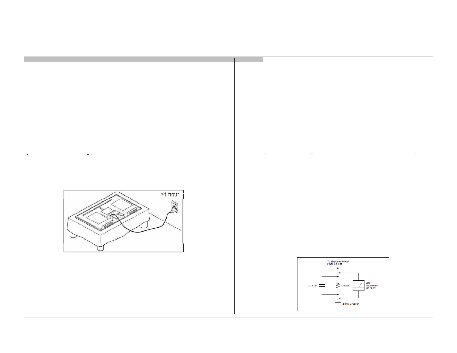
10) During the repair, DO NOT leave the Power On or Burn-in period for more than
1 hour while the TV is face down on a cloth.
Figure 1. TV is faced down on a cloth during repair.
1-2. Safety Check-Out
After correcting the original service problem, perform the following safety checks
before releasing the set to the customer:-
1) Check the area of your repair for unsoldered or poorly soldered connections.
.
2) Check the interboard wiring to ensure that no wires are pinched or contact
high-wattage resistors.
KLV-24 EX430
RM-GA022
hardware have been replaced. Be absolutely certain you have replaced all
the insulators.
4) Look for unauthorized replacement parts, particularly transistors that were
installed during a previous repair. Point them out to the customer and
recommend their replacement.
5) Look for parts which, though functioning show obvious signs of deterioration.
Point them out to the customer and recommend their replacement.
6) Check the line cords for cracks and abrasion. Recommend the replacement
of any such line cord to the customer.
7) Check the antenna terminals, metal trim, metallized knobs, screws and all
other exposed metal parts for AC leakage. Check leakage test as described
next.
8. For safet
1-3. Leakage Test
The AC leakage from any exposed metal part to earth ground and from all exposed
metal parts to any exposed metal part having a return to chassis must not exceed
0.5mA (500 microamperes).
Leakage current can be measured by any one of the three methods:-
Follow the manufacturers instructions to use those instructions.
2) A battery-operated AC milliampmeter The DATA PRECISION 245 digital
multimeter is suitable for this job.
3) Measuring the voltage drop across a resistor by means of a VOM or battery
operated AC voltmeter. The 'limit' indication is 0.75V so analog meters must
have an accurate low voltage scale. The SIMPSON'S 250 and SANWA
battery operated digital multimeter that have a 2 VAC range are suitable.
(see Figure 2.)
reasons, repairing the Power board and/or Inverter board is prohibited.
are examples of passive
are suitable. Nearly all
.
Figure 2. AC voltmeter to check AC leakage
5
Safety Notes
1-4. H
d
)
4
) B
)ppg
for safe operation are identified in this manual. Follow these procedures
desi
thi
KLV-24 EX430
RM-GA022
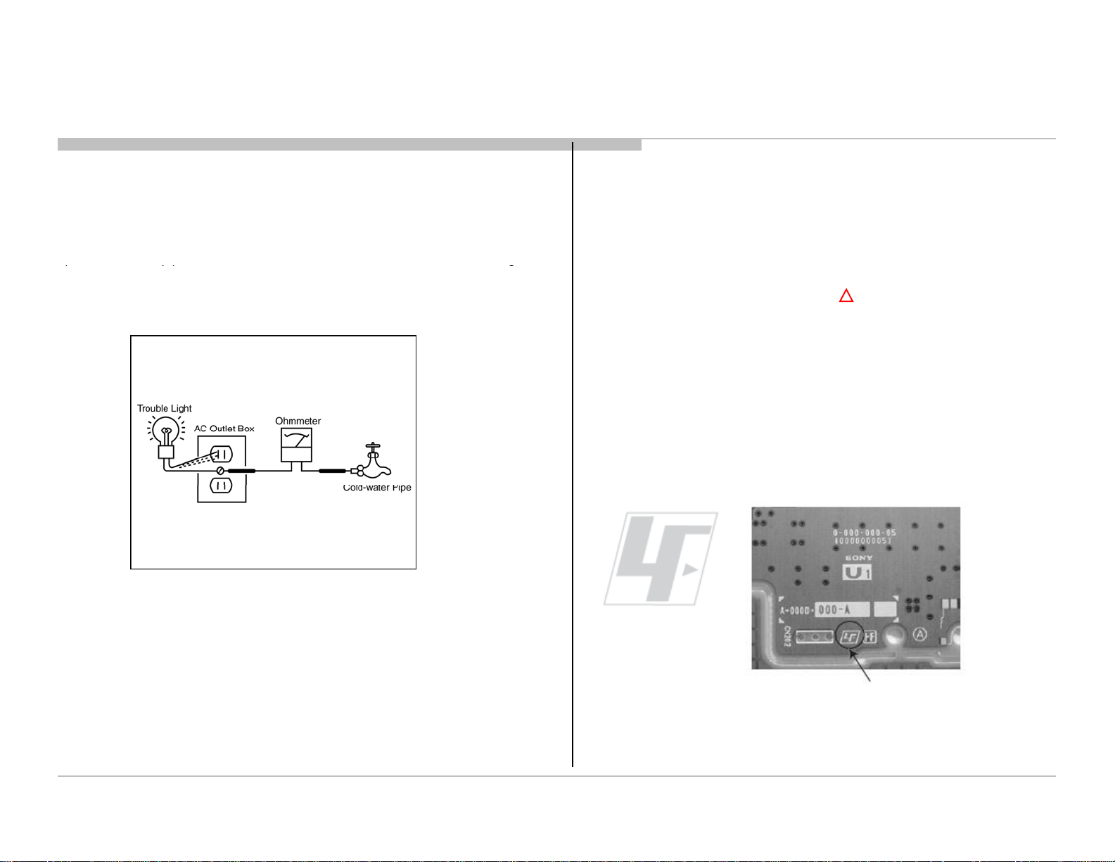
ow to Find a Good Earth Groun
1) A cold-water pipe is a guaranteed earth ground; the cover-plate retaining
screw on most AC outlet boxes is also at earth ground.
2) If the retaining screw is to be used as your earth ground, verify that it is at
ground by measuring the resistance between it and a cold-water pipe with an
ohmmeter. The reading should be zero ohms.
3
If a cold-water pipe is not accessible, connect a 60- to 100-watt trouble- light
(not a neon lamp) between the hot side of the receptacle and the retaining screw.
Try both slots, if necessary, to locate the hot side on the line; the lamp should
light at normal brilliance if the screw is at ground potential (see Figure 3).
e sure to follow these guidelines to protect your property and avoid causing
serious injury.
• Carry the TV with an adequate number of people; larger size TVs require
two or more people.
• Correct hand placement while carrying the TV is very important for safety
and to avoid damages.
5) Components identified by shading and mark on the exploded views, and
in the parts list are critical for safe operation. Replace these components with
Sony parts whose part numbers appear as shown in this manual or in
supplements published by Sony. Circuit adjustments that are critical
whenever critical components are replaced or improper operation is suspected.
!
1-6. Lead Free Information
The circuit boards used in these models have been processed using Lead Free
Solder. The boards are identified by the LF logo located close to the board
gnation.
Figure 3. Checking for earth ground.
1-5. Warnings and Caution
1) These servicing instructions are for use by qualified service personnel only.
2) To reduce the risk of electric shock, do not perform any servicing other than
that contained in the operating instructions unless you are qualified to do so.
3) An isolation transformer should be used during any service to avoid possible
shock hazard, because of live chassis. The chassis of
connected to the ac power line.
s receiver is directly
Figure 4: LF
Logo
Figure 5: LF logo on circuit board
6
Safety Notes
7-640-005-19
0.3mm
0.25Kg
,
,
The servicing of these boards requires special precautions. It is strongly
recommended to use Lead Free Solder material in order to guarantee optimal
quality of new solder joints. Lead Free Solder is available under the following
part numbers:-
Part Number Diameter Remarks
7-640-005-20 0.4mm 0.50Kg
7-640-005-21 0.5mm 0.50Kg
7-640-005-22 0.6mm 0.25Kg
7-640-005-23 0.8mm 1.00Kg
7-640-005-24 1.0mm 1.00Kg
7-640-005-25 1.2mm 1.00Kg
7-640-005-26 1.6mm 1.00Kg
Due to high melting point of Lead Free Solder, the soldering iron tip
temperature needs to be set to 370 degrees centigrade. This requires
soldering equipment capable of accurate temperature control coupled
with a good heat recovery characteristics.
For more information on the use of Lead Free Solder
please refer to http://www.sony-training.com
KLV-24 EX430
RM-GA022
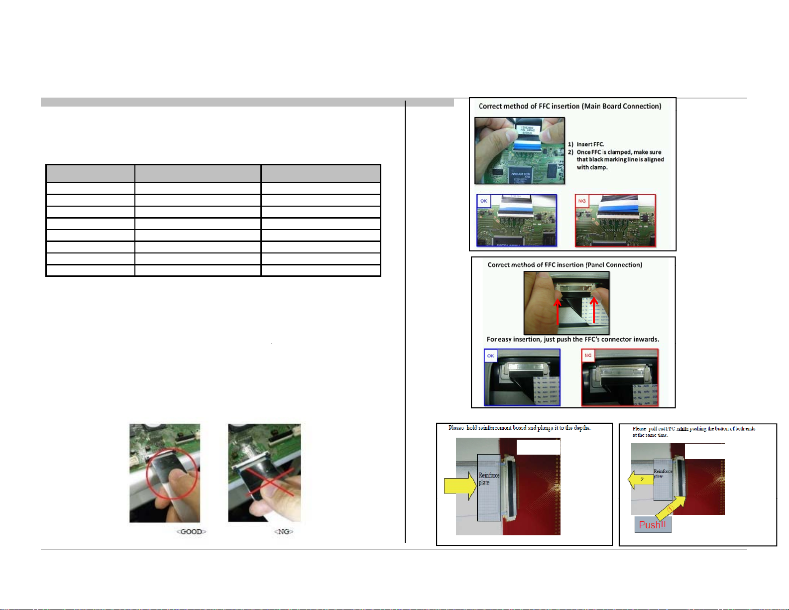
1-7. Handling the FLEXIBLE FLAT CABLE (FFC)
When you insert / pull out FFC, please grasp a reinforcement board
and main body of FFC.
< Insertion>
B** Board
<Pull out>
B** Board
7

Safety Notes
N
diff
1-8. Disassemble Rear Cover (24”)
KLV-24 EX430
RM-GA022
ote : Picture provided in this section might have slight
1-9. Assemble Rear Cover (24”)
erence from the actual sets.
Screws detail refer to Section 6
Please press the set (until hear click sound)
before put at the stand.
Screws detail refer to Section 6
8
SECTION 2
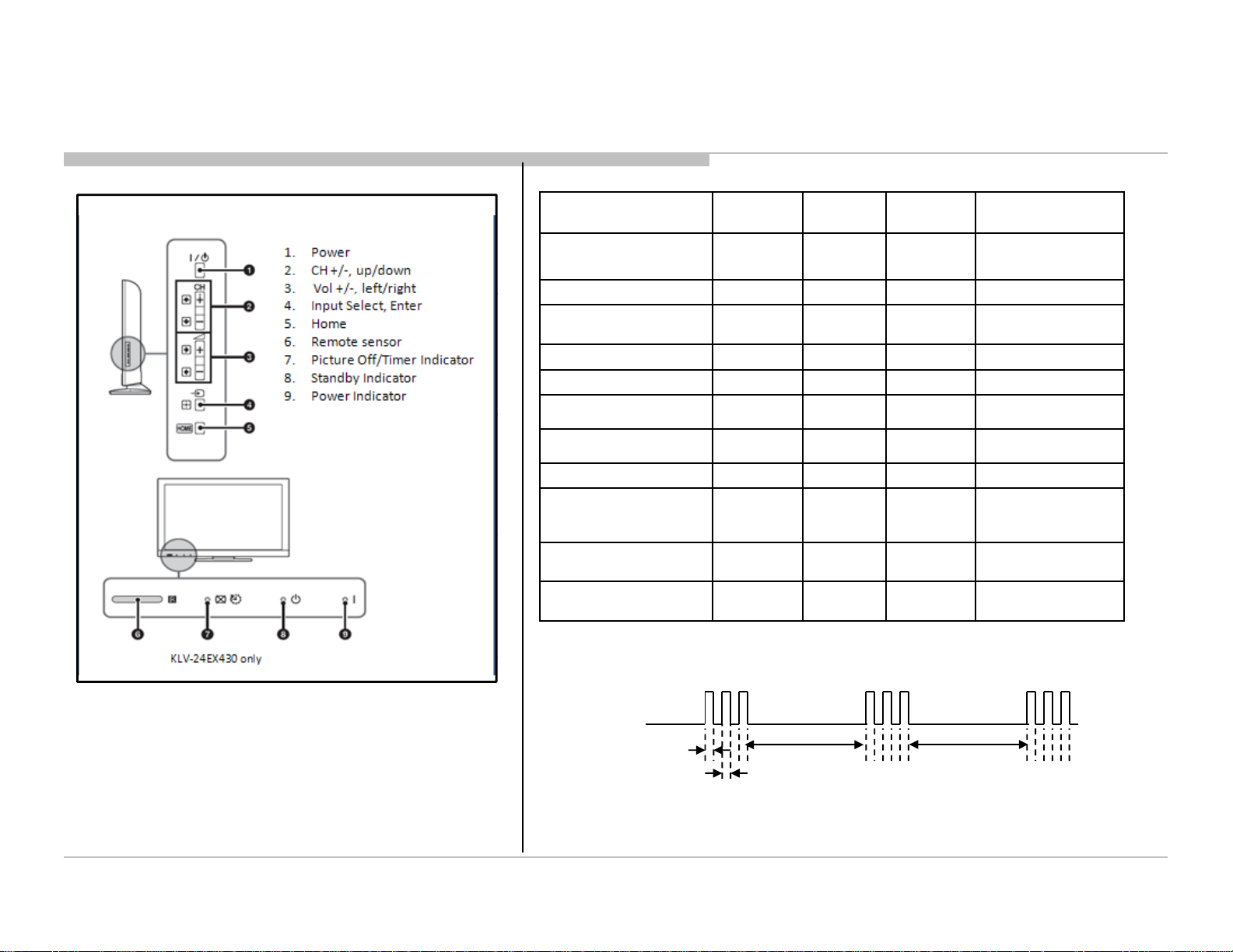
2-2. LED Displ
l
Power On
OFF
OFF
Green
Set On Timer ( Power On )
Orange
Off
Green
Wh
LED displ
SELF DIAGNOSTIC FUNCTION
KLV-24 EX430
RM-GA022
2-1. Overview of Control Buttons
ay Contro
Status Picture Off/
Power Off
( AC Off and *1)
Standby
( by remote control off only )
Picture Off Green Off Green
Set "Sleep Timer" Orange Off Green
"
Set "On Timer"( Standby ) Orange Red Off
Picture Frame Orange Off Green
Failure Off
Error of panel ID
Software Updating
"
Timer LED
OFF OFF OFF
OFF Red OFF
Orange
Blinking
Orange
Blinking
Standby
LED
Red
Blinking
Off
Red Off
Power LED Remarks
Off
Green
Blinking
*1 power switch off (by
side key)
The number of LED
blinking indicates
cause of failure.
Blinking:0.5sec On /
0.5sec Off
2-3. LED Pattern
en safety shutdown occurs, Standby
patterns as indicated below
.
0.5sec
0.5sec
Example: The figure above shows LED display when SHUTDOWN is caused by Audio
Error. It repeats flashing for a specified number of times in 0.5sec/cycle and has a 3 seconds
interval of lighting off. Please note that a 3 seconds interval of lighting off is fixed regardless of abnormal state types.
ay reports the cause by using the lightning
3.0sec 3.0sec
9
Self Diagnostic Function
y
5
board
anel5
anel 5
ed
5
Panel Power
Error
boa d o / a e
ae_5
o
ae5 aed
Board
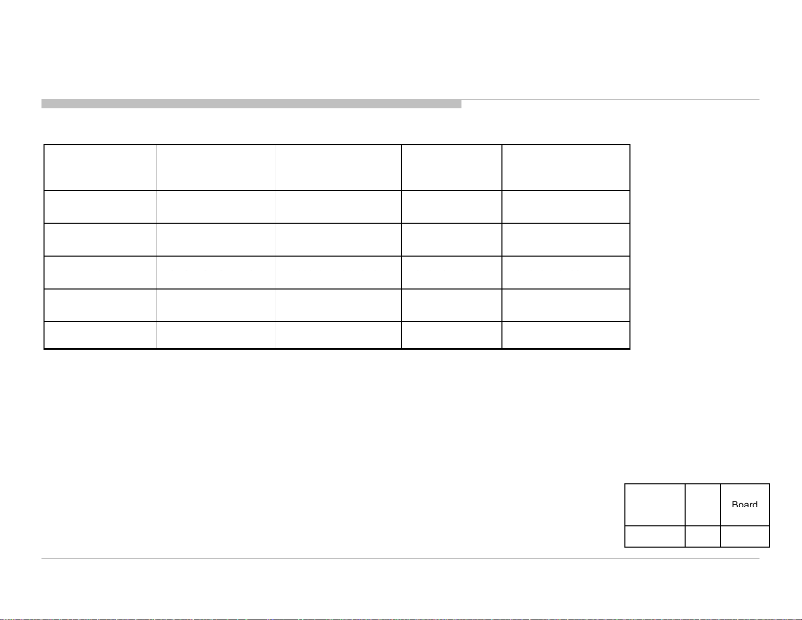
2-4. Standby LED Error Displa
KLV-24 EX430
RM-GA022
Note: Details refer to Troubleshooting Section.
The Number of
Detection Items Board / Error Item Monitoring Items Content
Standby LED
(RED blinking)
2 Main Power Error Adapter Error REG19.5V_MON Reg 19.5 V failed
3 Audio Error B* board Error INT_LINE Audio failure
B*
Error/PanelP
VMonP
_
Tcon Error
6 Backlight Error B* board Error/Panel
BL_ERR Backlight Error
Backlight Error
- RTC Error B* board Error RTC 12C ACK RTC IC Failed
Note : When RTC error occurs, Shutdown error count for RTC error is incremented by 1.
TV does not go to Safety Shutdown. Standby LED does not flash.
V fail
Segment Size B*
Type
P-2L 24 B2FN
10

Self Diagnostic Function
r
Tact SW board
Joint Connector
▲▲▲▲▲▲▲▲▲▲▲
2-5. Triage Chart
KLV-24 EX430
RM-GA022
B2F-N Board
HL-24 Board
AC Adaptor
T-Con Board
Speaker Unit
Panel Module
FFC Cable
Blinking
23 56
●●●●● ● ● ● ● ●● ● ●● ● ● ●●●●
●
●
● ●▲▲▲▲▲▲▲
▲
●
Doubtful part problem
▲
Few possibility
Tuner Video1 VIdeo2 Component HDMI MHL PC Main Speake
●
No Picture No Sound
HP Video1 Video2 Component Tuner HDMI MHL USB
Note: Details refer to Troubleshooting Section.
11
Troubleshooting
No Power
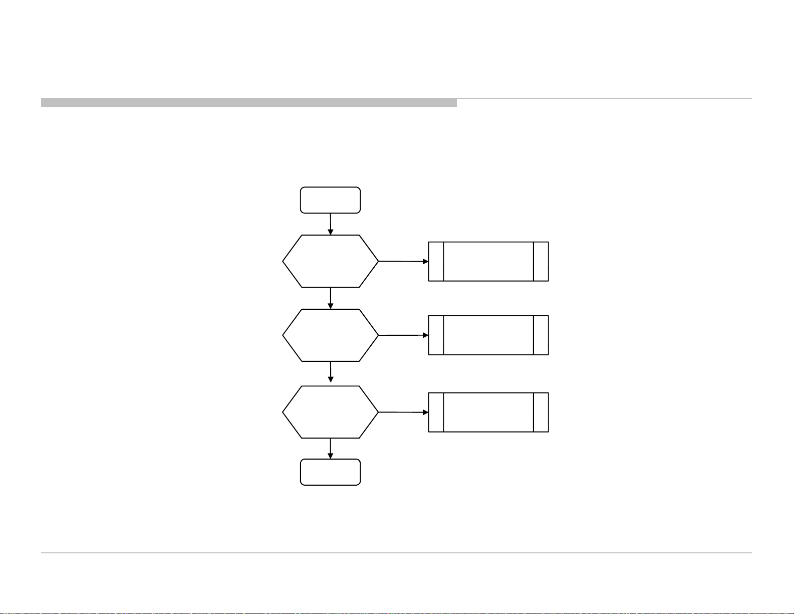
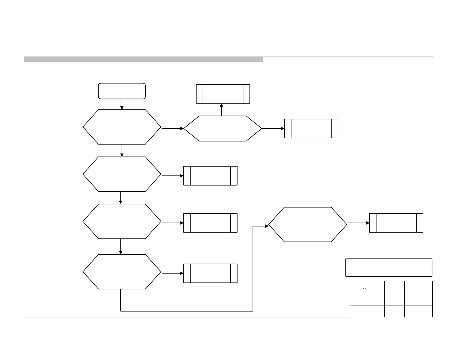
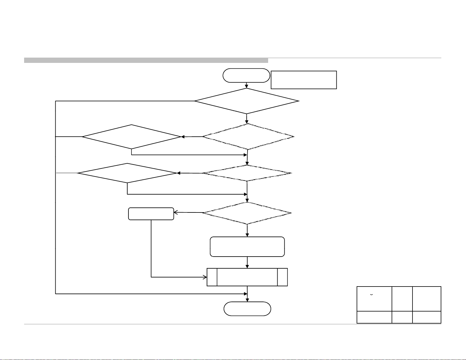
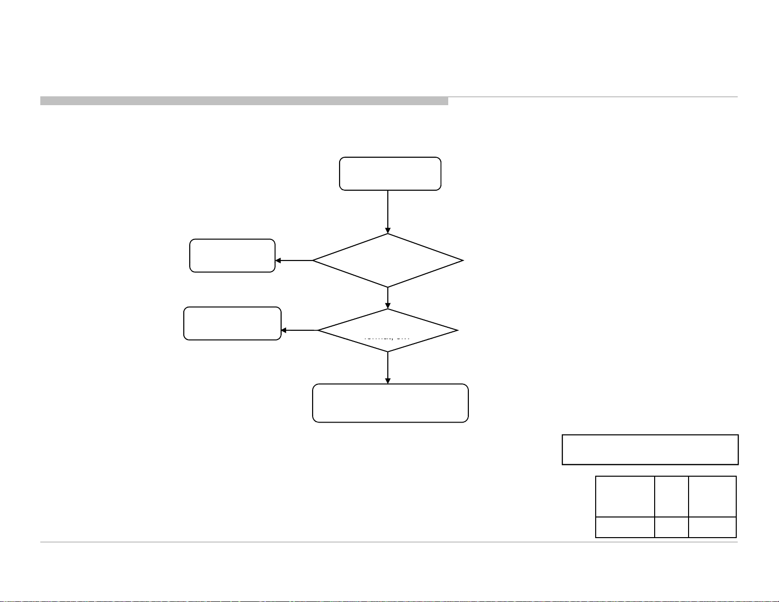
3-1. Troubleshooting Flow
SECTION 3
TROUBLESHOOTING
START
KLV-24 EX430
RM-GA022
Does the Power Led
stay on when the
TV is switched on ?
OK
Is the Standby Led
blink ?
OK
Is the Picture and
Sound OK ?
END
NG
See
NG
See
Standby LED Blink
NG
See Audio/Video
Troubleshooting doc.
Note:
1. Details refer to each Troubleshooting Section.
2. Refer to Troubleshooting Reference location.
12
Troubleshooting
r
pg
No
Board
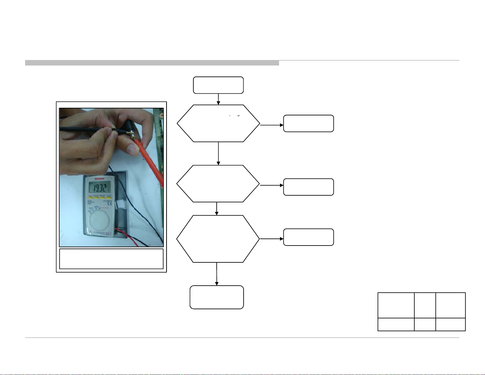
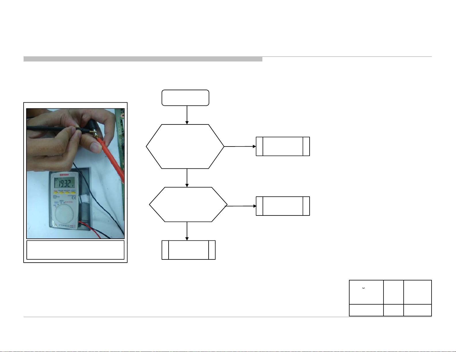
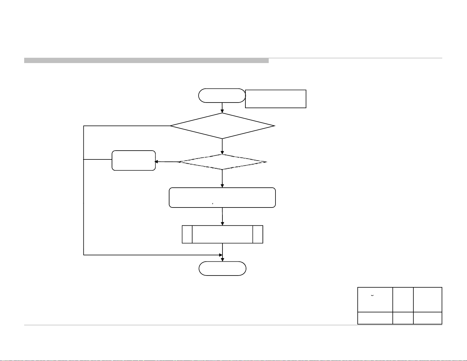
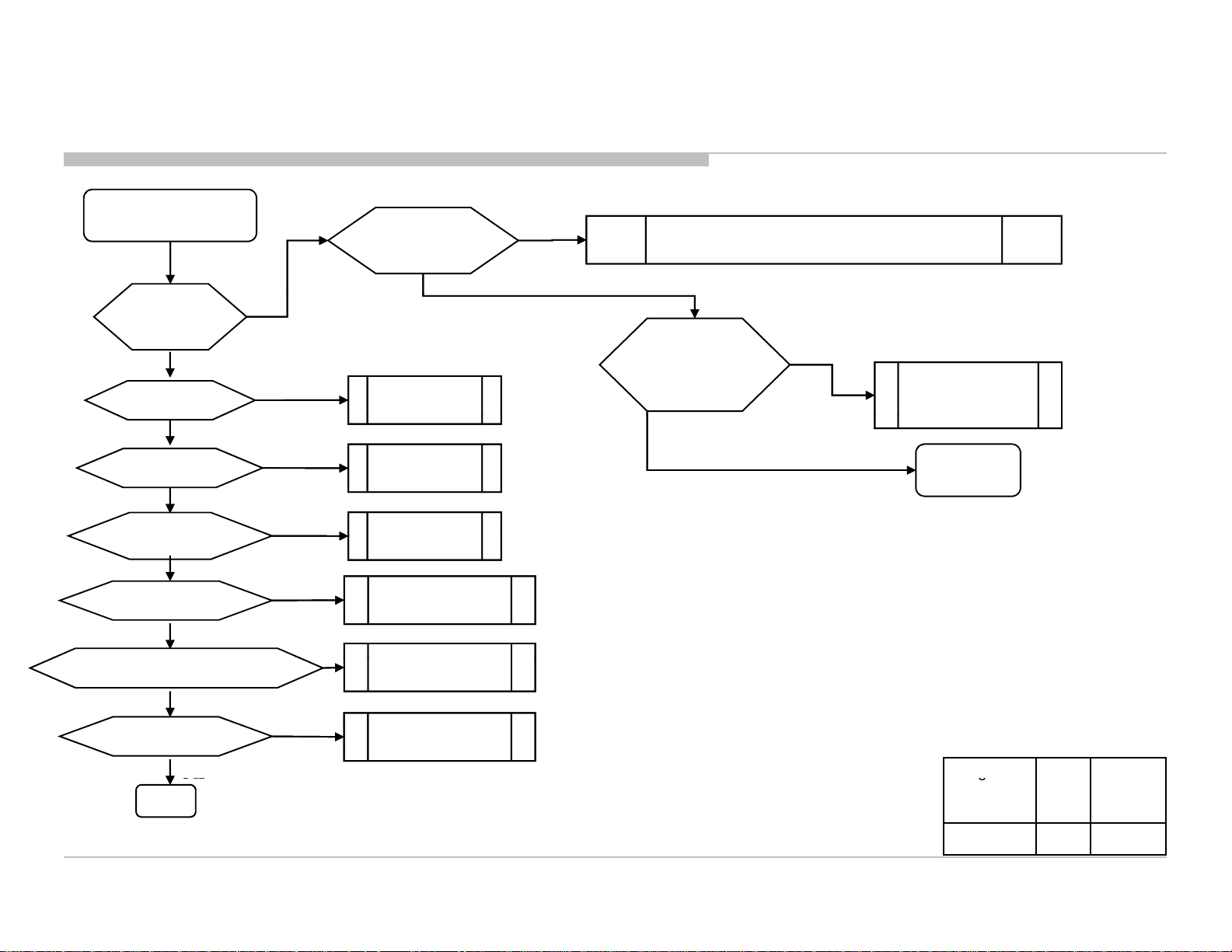
3-2. No Powe
No Power
Take out AC plug
and test AC supply.
Within ±10% of adaptor
rated input voltage?
Yes
KLV-24 EX430
RM-GA022
AC source
Figure 1: How to test DC voltage at
adaptor output
Take out adaptor
and test at adaptor
output is it 18V – 19.5V?
(Refer Figure 1)
Yes
Plug in adaptor and check
DC voltage at JL6023
Is it 19.5V?
Yes
•See DDCON
Sheet
No
Adaptor
No
B* board
Segment Size B*
Type
P-2L 24 B2FN
13
Troubleshooting
Yes
g
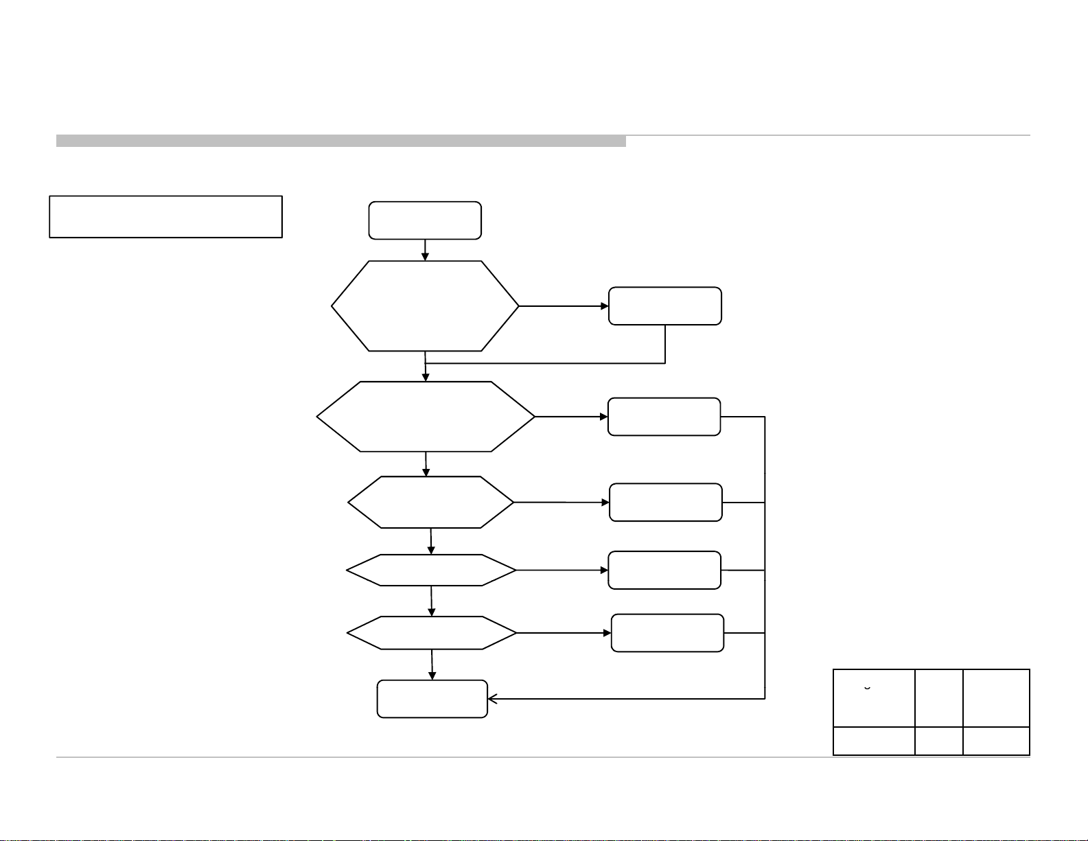
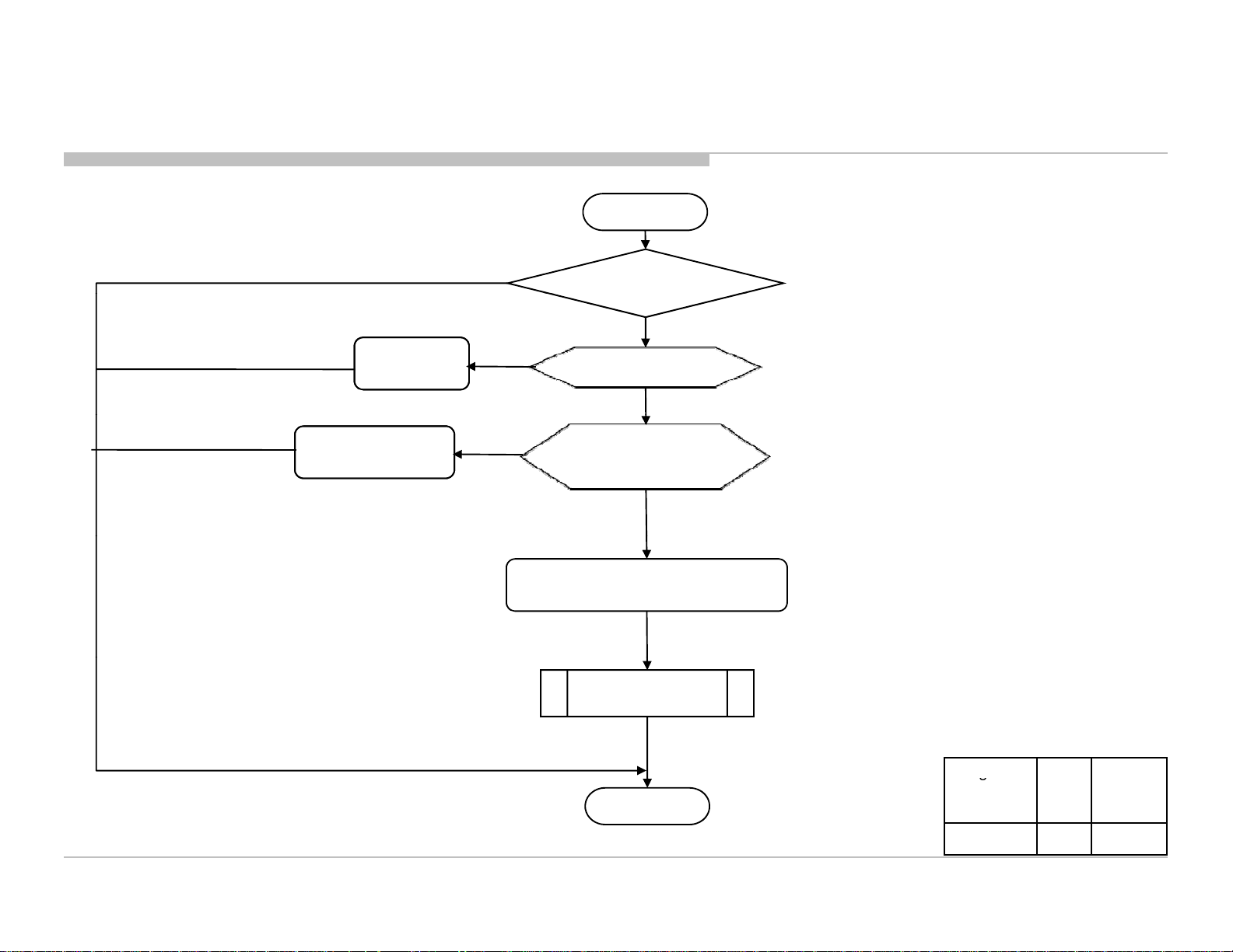
3-2-1. *DDcon
KLV-24 EX430
RM-GA022
Start
Check voltage at JL6012
is it 3.3V?
Yes
Check voltage at JL6010
is it 1.2V?
Check voltage at JL6011
is it 1.5V?
Yes
No
No
DDCON
OK
Check F6000
Change B*
board
Change B*
board
NGNo
Fuse
Check voltage at JL6020
is it 5V?
No
Change
B*board
Check voltage at JL6013
is it 5V?
No
Change B*
board
Yes
After checking, take note of
NG condition & change B board
Segment Size B*
Board
Type
P-2L 24 B2FN
14
Troubleshooting
3-3-1
blinking
Is it 18V
5V?
Yes
g
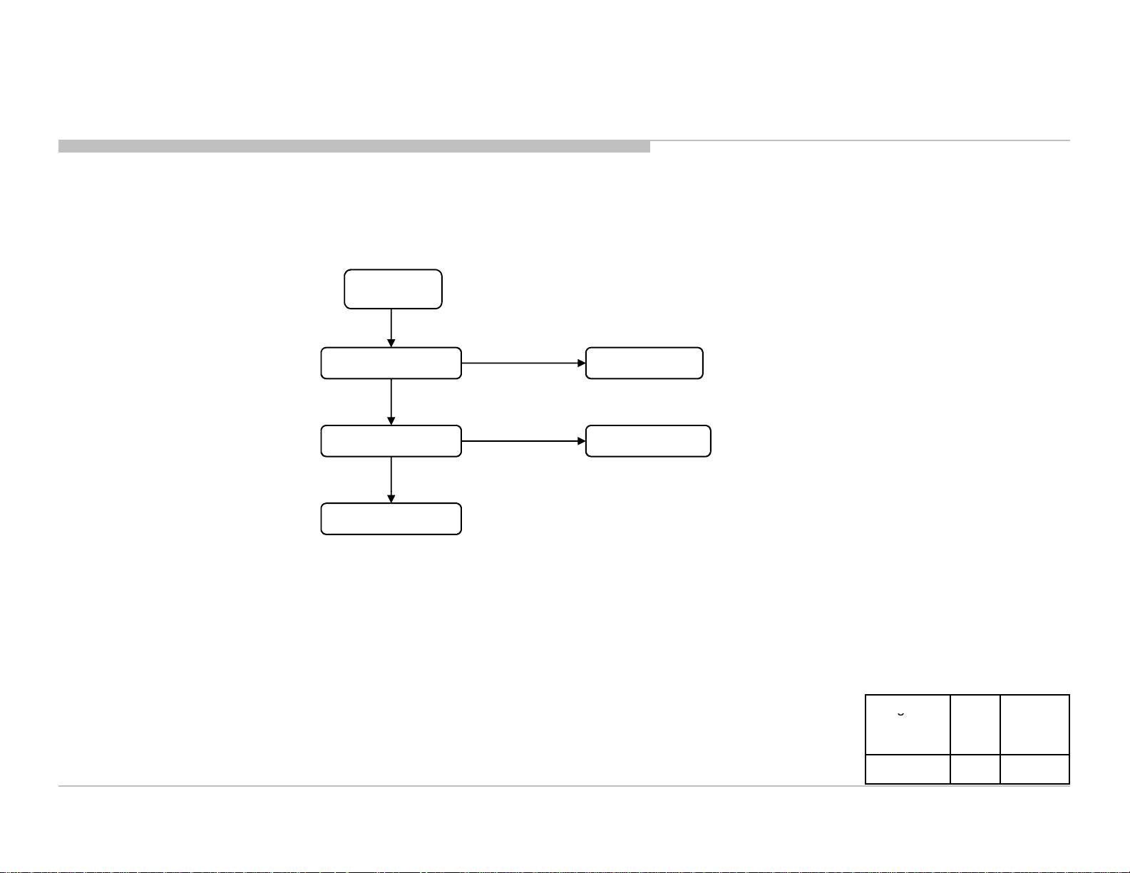
3-3. Standby Led Blinking
KLV-24 EX430
RM-GA022
. 2-times Led
2 times Blinking
Check DC voltage at
JL6023
-19.
No
Take out adaptor
and test at adaptor
output is it 18V – 19.5V?
(Refer Figure 2)
No
Yes
Change
B*board
Change
B*board
Figure 2: How to test DC voltage
at adaptor output
Change
adaptor
Segment Size B*
Board
Type
P-2L 24 B2FN
15

Troubleshooting
Speaker Connector
Check Speaker harness
Change
Harness
Check
No 3x blinking
IC4002 d
g
3-3. Standby Led Blinking
3-3-2. 3-times Led blinking
KLV-24 EX430
RM-GA022
START
F4000 broken
3x blinking
at CN4000 & perform
3x blinking
No connectivity
of F4000
3x blinking
& F4000 OK
Audio IC problem
Remove
AC OFF - ON
3x blinking
connectivity
at F4000.
amage
No 3x blinking
Speaker Connector to CN4000
and Speaker impedance
No connectivity
for speaker harness
Change
Speaker
Connect back
& perform AC OFF - ON
Speaker impedance
≠ 7~8 Ω
Speaker
Change B*
board
DONE
Segment Size B*
Board
Type
P-2L 24 B2FN
16
Troubleshooting
+5V is OK
g
3-3. Standby Led Blinking
3-3-3. 5-times Led blinking
KLV-24 EX430
RM-GA022
Note :
PANEL_VCC_SW = +5V±10%
Check PANEL_VCC_SW
on B* Board:
(Probe Pin 1 at CN8700)
Remove and reinsert
LVDS Flat Flexible Cable (FFC)
at B* Board and Panel
5x Blinking is Still Observed
Replace LVDS
Flat Flexible Cable
5x Blinking is Still Observed
Replace B* Board
5x Blinking is Still Observed
Replace Panel
START
+5V is not
within spec.
5x Blinking is Still Observed
TV Boot Up
Normally
TV Boot Up
Normally
TV Boot Up
Normally
TV Boot Up
Normally
Troubleshoot
+5V DDCON
FFC Insertion
Issue
Flat Flexible Cable
Issue
B* Board Issue
Panel Issue
END
Segment Size B*
Board
Type
P-2L 24 B2FN
17
Troubleshooting
g
3-3. Standby Led Blinking
3-3-4. 6-times Led blinking
6x blinking
Symptom gone
Change B* Board
B* board
6x blinking
Symptom gone
Change Harness Harness
KLV-24 EX430
RM-GA022
6x blinking
Change Panel
Segment Size B*
Board
Type
P-2L 24 B2FN
18
Troubleshooting
No Sound
Refer USB Audio
3-4. Audio Problem
KLV-24 EX430
RM-GA022
Audio Problem
Main Speaker No Sound
HP Out No Sound
*V1, V2/D1 or
PC/HDMI analog
no sound?
Analog RF
no sound?
HDMI Audio
no sound?
USB Audio
no sound?
Refer “Main Speaker
No Sound”
Refer “HP Out
No Sound”
Refer “Analog Audio
Input
”
Refer “Analog RF
No Sound”
Refer “HDMI Audio
No Sound”
“
No Sound”
* V1 = Video1, V2 = Video2,
D1 = Component1
19
Troubleshooting
3-4-1. Main S
OK
NG
IC4002 d
g
3-4. Audio Problem
peaker No Sound
OK
START
Do a Factory Setting
KLV-24 EX430
RM-GA022
Main Speaker No Sound
OK
OK
Change Harness
Change Speaker
F4000 broken
NG
NG
NG
NG
Speaker Harness
connectivity
NG
Speaker Impedance
7~8 Ω
OK
Check fuse connectivity
at F4000
OK
Audio IC problem
amage
Change B* Board
DONE
Segment Size B*
Board
Type
P-2L 24 B2FN
20
Troubleshooting
3-4-2. Headph
(HP) O
d
p
Headphone
p
g
3-4. Audio Problem
KLV-24 EX430
RM-GA022
one
ut No Soun
problem
START
OK
Do a Factory Setting
NG
OK
Use another Headphone
NG
HP IC (IC4001) or Main IC (IC5000)
roblem
Change B* Board
Headphone (HP) No
Sound
DONE
Segment Size B*
Board
Type
P-2L 24 B2FN
21
Troubleshooting
3-4-3. Analog Audio I
d
g
3-4. Audio Problem
KLV-24 EX430
RM-GA022
nput No Soun
RCA cable
RCA cable
problem
problem
Analog Input
Analog Input
Source problem
Source problem
OK
OK
OKOK
START
Do a Factory Setting
NG
Use another RCA cable
NG
Check Analog Input Source
& use another input source
NG
HP IC (IC4001) or Main IC (IC5000)
or Audio IC (IC4002) problem
Analog Audio Input No Sound
Change B* Board
Segment Size B*
Board
DONE
P-2L 24 B2FN
Type
22

Troubleshooting
3-4-4. HDMI Audio No S
d
g
3-4. Audio Problem
KLV-24 EX430
RM-GA022
oun
HDMI Audio input
no sound
Change
HDMI cable
Change HDMI
source
Change to supported
format
NG
NG
NG
HDMI cable,
ok?
OK
HDMI source,
ok?
OK
*HDMI sound
format ok?
OK
Change B* Board
* Please refer to IM for supported HDMI
audio format.
Segment Size B*
Board
Type
P-2L 24 B2FN
23

Troubleshooting
3-4
OK
g
3-4. Audio Problem
-5. Analog RF no sound
KLV-24 EX430
RM-GA022
Analog RF input no
sound
Change RF
cable
Change RF
source/channel
Refer “Speaker
No Sound”
Refer “Tuner
Problem”
NG
NG
NG
NG OK
RF cable,
ok?
RF source,
ok?
OK
Raster sound,
ok?
OK
Tuning,
ok?
UI setting, ok?
(TV System, AFT, Audio Filter)
OK
Change B* Board
NG
Correct UI
Segment Size B*
Board
Type
P-2L 24 B2FN
24
Troubleshooting
3-4-6. USB
d
USB thumbdrive
thumbdrive
format, ok?
3-4. Audio Problem
no soun
KLV-24 EX430
RM-GA022
USB Audio input
no sound
OK
Change USB
Change to
supported format
NG
,
ok?
OK
NG
*USB audio
OK
Change B* Board
* Please refer to IM for supported USB
audio format.
Segment Size B*
Board
Type
P-2L 24 B2FN
25
Troubleshooting
Setting
Video
OK?
Refer “
HDMI/MHL
Yes
g
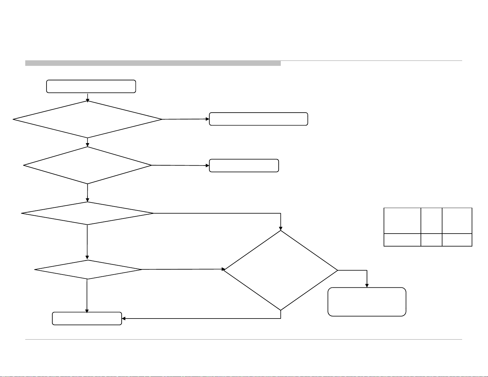
3-5. Video Problem
Picture On Screen
Distorted Or Missing
Check LED 6x
times blink?
Yes
KLV-24 EX430
RM-GA022
Refer to Power Troubleshoot (STANDBY LED
BLINK 6x times blinking
Backlight
turns ON?
Yes
Tuner, OK?
Yes
Video 1, OK?
Yes
2,
Yes
Component, OK?
Yes
HDMI/MHL, OK?
Yes
PC, OK?
No
No
No
No
No
No
No
No
Refer “Tuner
Problem”
Refer “Video 1
Problem”
Refer “Video 2
Problem”
Refer “Component
Problem”
Problem”
Refer “PC
Problem”
Check Eco
Power Saving
ON?
No
Yes
Refer to IM Eco
Power Saving
Change B*
Board
Finish
Segment Size B*
Board
Type
P-2L 24 B2FN
26
Troubleshooting
3-5-1. Tuner Troubleshooting Flow
Check RF source cable
Ch
d
Rast
OK?
S
t
SizeB*
cable
3-5. Video Problem
Analog RF input no picture
KLV-24 EX430
RM-GA022
and antenna, OK?
OK
Check JL1003 =
+3.3V?
OK
er,
OK
Tuning, OK?
NG
NG
NG
NG
OK
Change RF cable and antenna
ange B* Boar
Check LVDS
harness
connection
between B* board,
OK?
egmen
Board
Type
P-2L 24 B2FN
NG
Reconnect LVDS cable
or change new LVDS
Change B* board
OK
27
 Loading...