How it Works
Log In / Sign Up
Buy Points
How it Works
FAQ
Contact Us
Questions and Suggestions
Users
Sony
Loading...
K
KLV-15SR
3
KLV-15SR1
14
klv 15sr1a
KLV-15SR1,KLV-17HR1
KLV-15SR1 - Lcd Wega&trade, Color Television
KLV-15SR2
5
KLV-15SR3E
6
KLV-15SR3U
KLV-17HR1
7
KLV-17HR2
6
KLV-17HR3
3
KLV-19T400
KLV-19T400A
KLV-19T400G
KLV-19T400W
KLV-19TV00A
KLV-19TV00G
KLV-19TV00W
klv 20g300a
3
KLV-20G300A-LAXG
KLV-20G400A
3
KLV-20S400A
2
KLV-20S400A/B
KLV-20S400A/D
KLV-20S400A/G
KLV-20S400A/L
KLV-20S400A/P
KLV-20S400B
KLV-20S400D
KLV-20S400G
KLV-20S400L
KLV-20S400P
KLV-20SR3
10
KLV-21SG2
14
KLV-21SR2
15
KLV-22BX205
KLV-22BX300
9
KLV-22BX301
6
KLV-22BX320
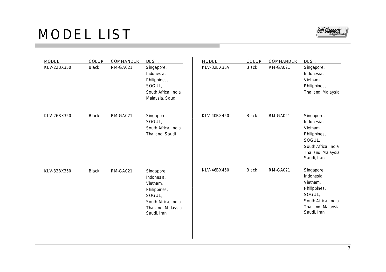
KLV-22BX350
2
KLV-22CX320
KLV-22CX350
KLV-22EX300
4
KLV-22EX310
KLV-22P402B
KLV-22S570A
2
KLV-22T550A
KLV-23
KLV-23HR1
5
KLV-23HR2
14
KLV-23HR3
6
KLV-23M1
6
KLV-23S200A
3
KLV-24EX430
KLV-24P412B
KLV-24P412C
KLV-24P422B
KLV-24R402A
3
KLV-24R422A
2
KLV-26
KLV-26BX200
KLV-26BX205
KLV-26BX300
10
KLV-26BX301
6
KLV-26BX320
3
KLV-26BX350
KLV-26CX320
KLV-26CX350
KLV-26EX
KLV- 26EX300
3
KLV-26EX(NX
KLV-26HG2
15
KLV-26HG2 Wega
KLV-26L500A
KLV-26M400A
4
KLV-26NX400
4
KLV-26S200A
6
KLV-26S200A,KLV-32S200A,KLV-40S200A,KLV-32S200,KLV-46S200A
KLV-26S400A
2
KLV-26S550A
2
KLV-26T400A
KLV-26T400A-G
KLV-26T400G
KLV-26TV00A
KLV-26TV00G
KLV-26U2520
3
KLV-26U2530
3
KLV-26U25xx
KLV-26U300A
KLV-26V300A
2
klv 32t200a
klv 32w400a
KLV- 40R472B
2
klv 40t200arm
klv 40w400a
klv 46w400a
klv 52w400a
klv v26a12u
klv v32a12u
klv wax3
Loading...
Loading...
Nothing found
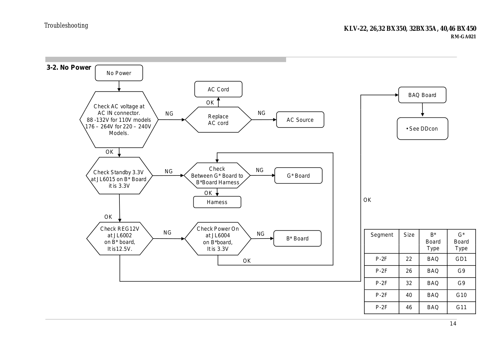
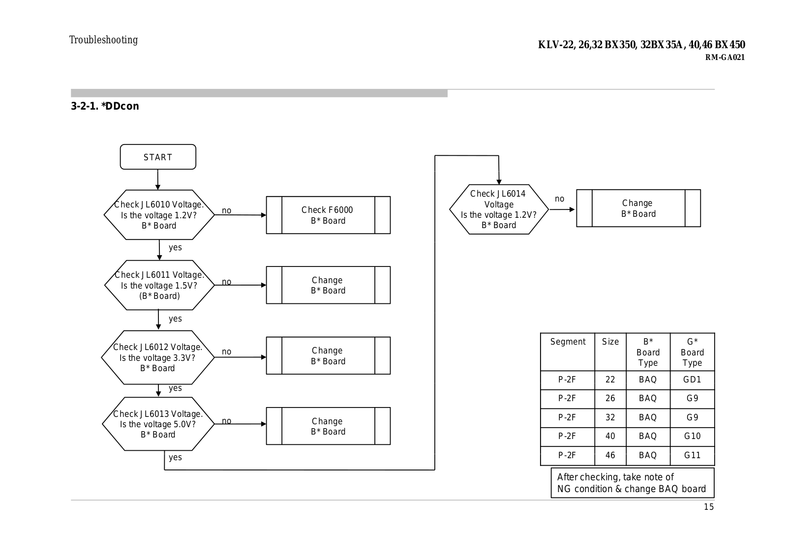
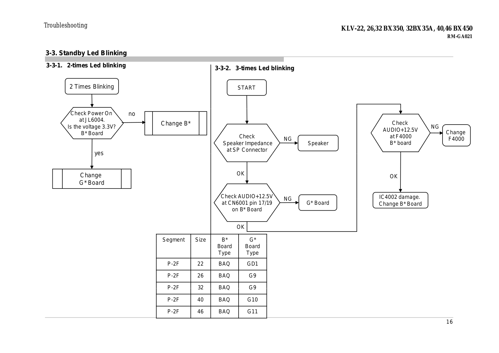
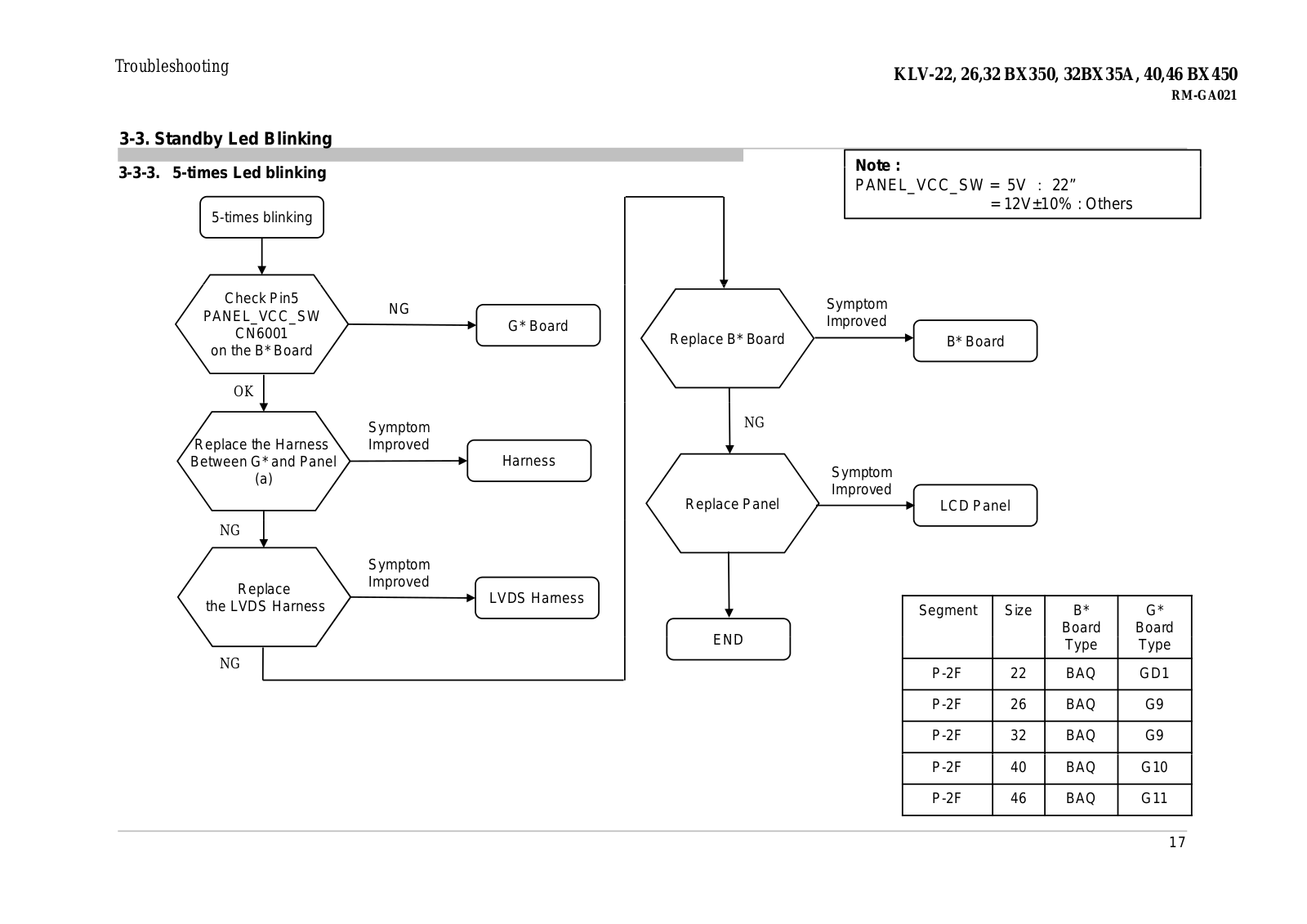
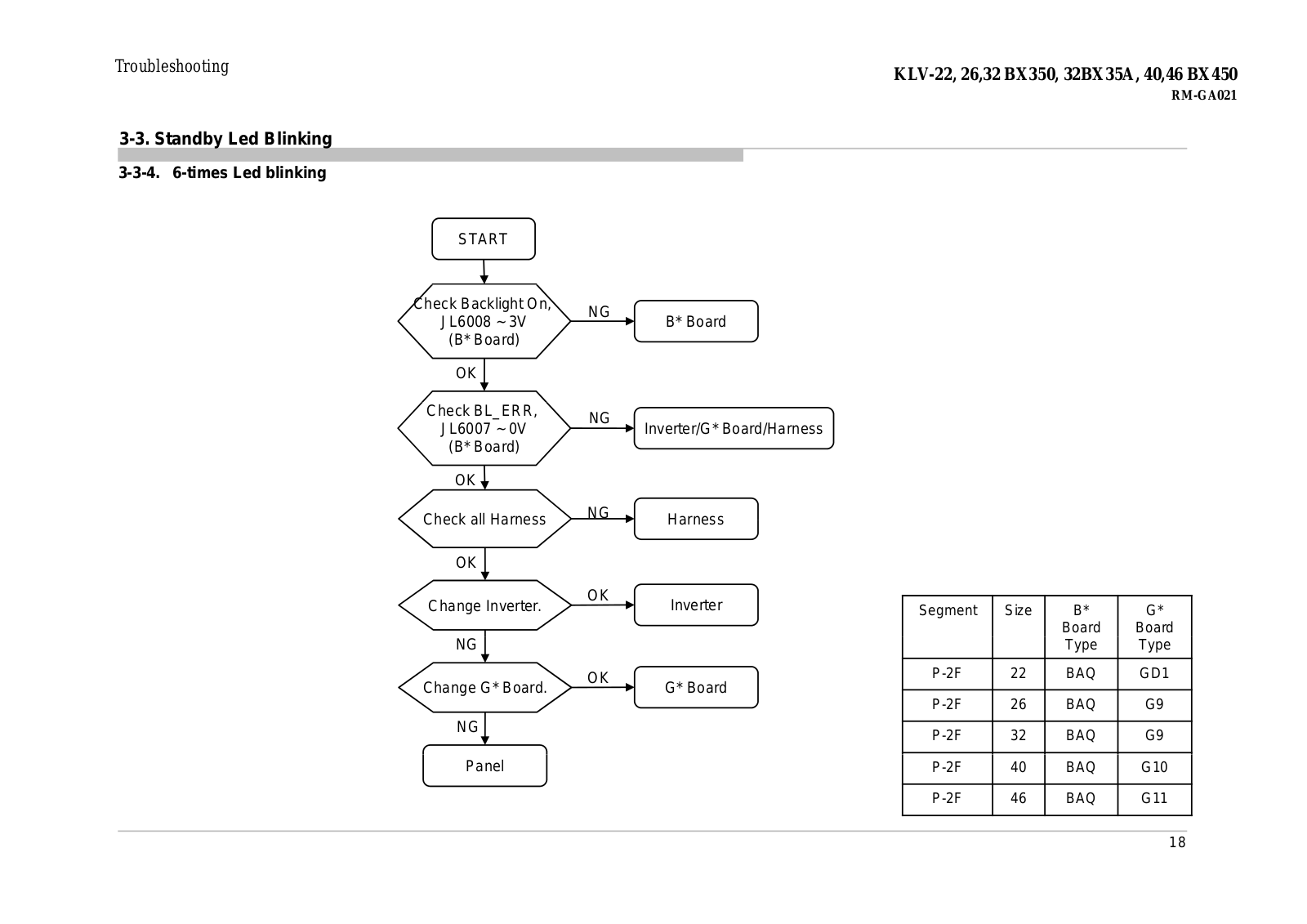
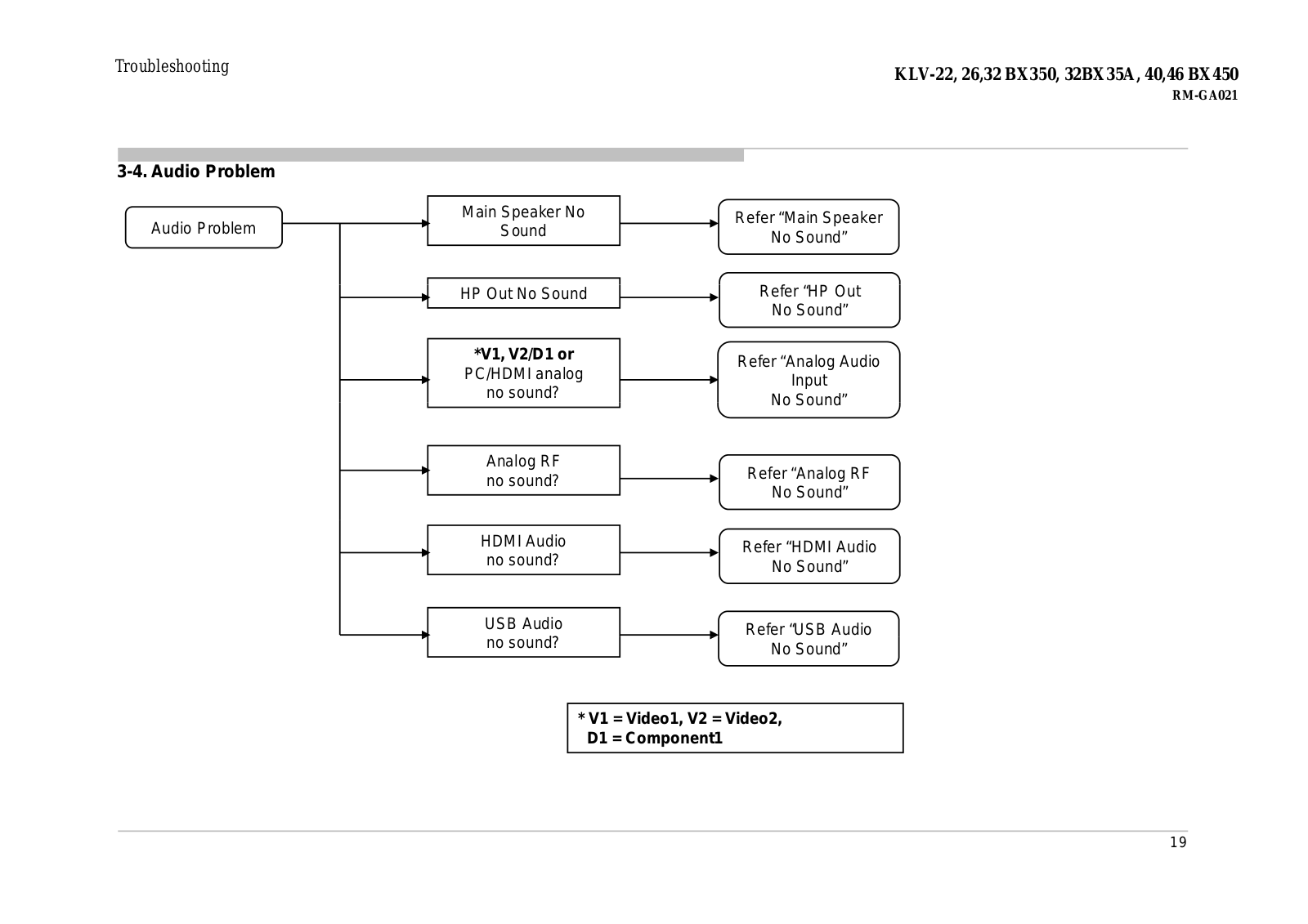
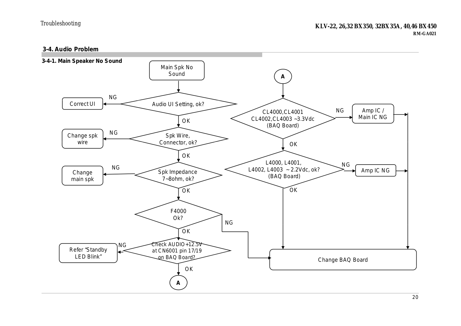
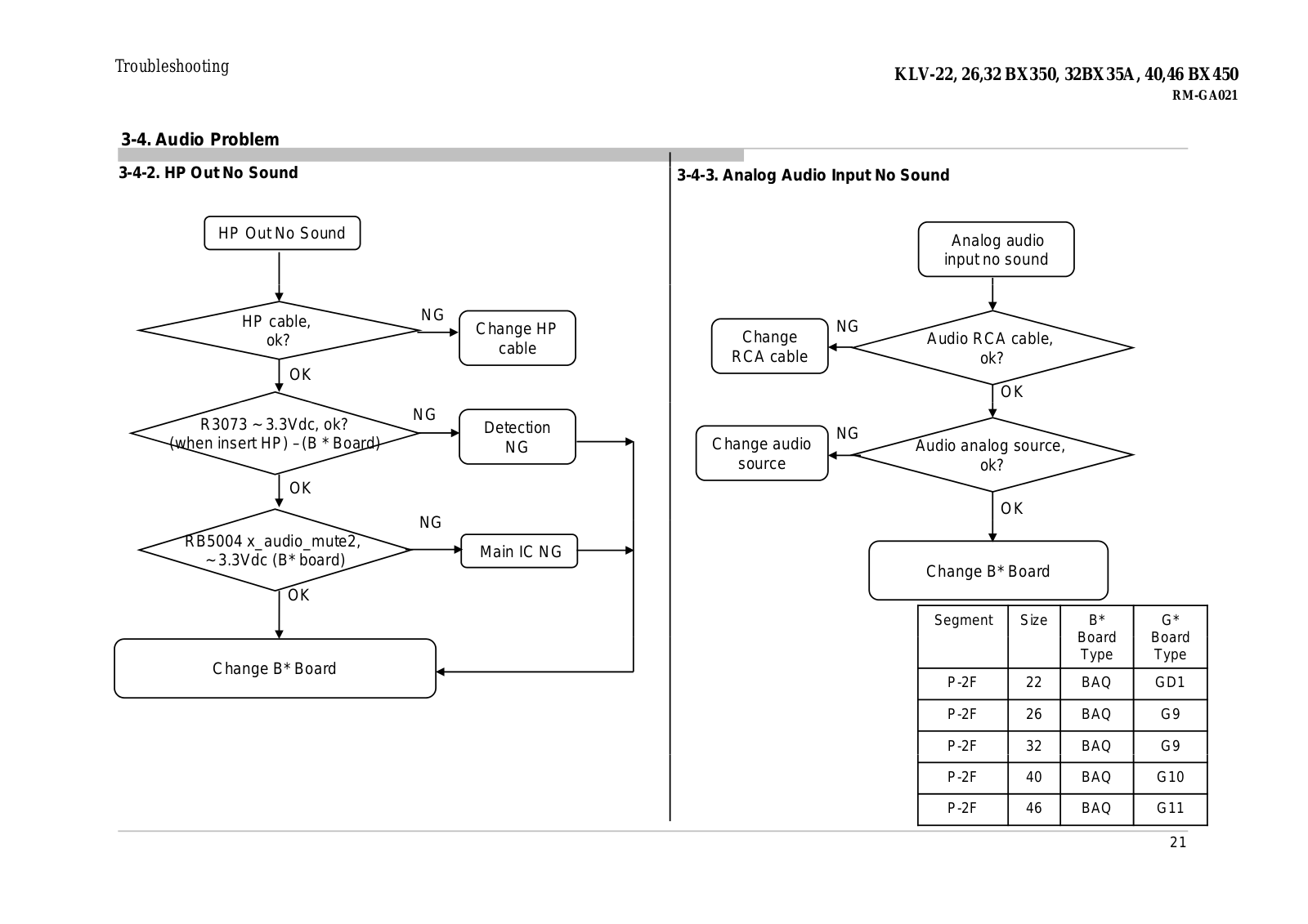
KLV-22BX350
Schematic
137 pgs
10.27 Mb
1
Operating Instructions Manual
32 pgs
4.06 Mb
0
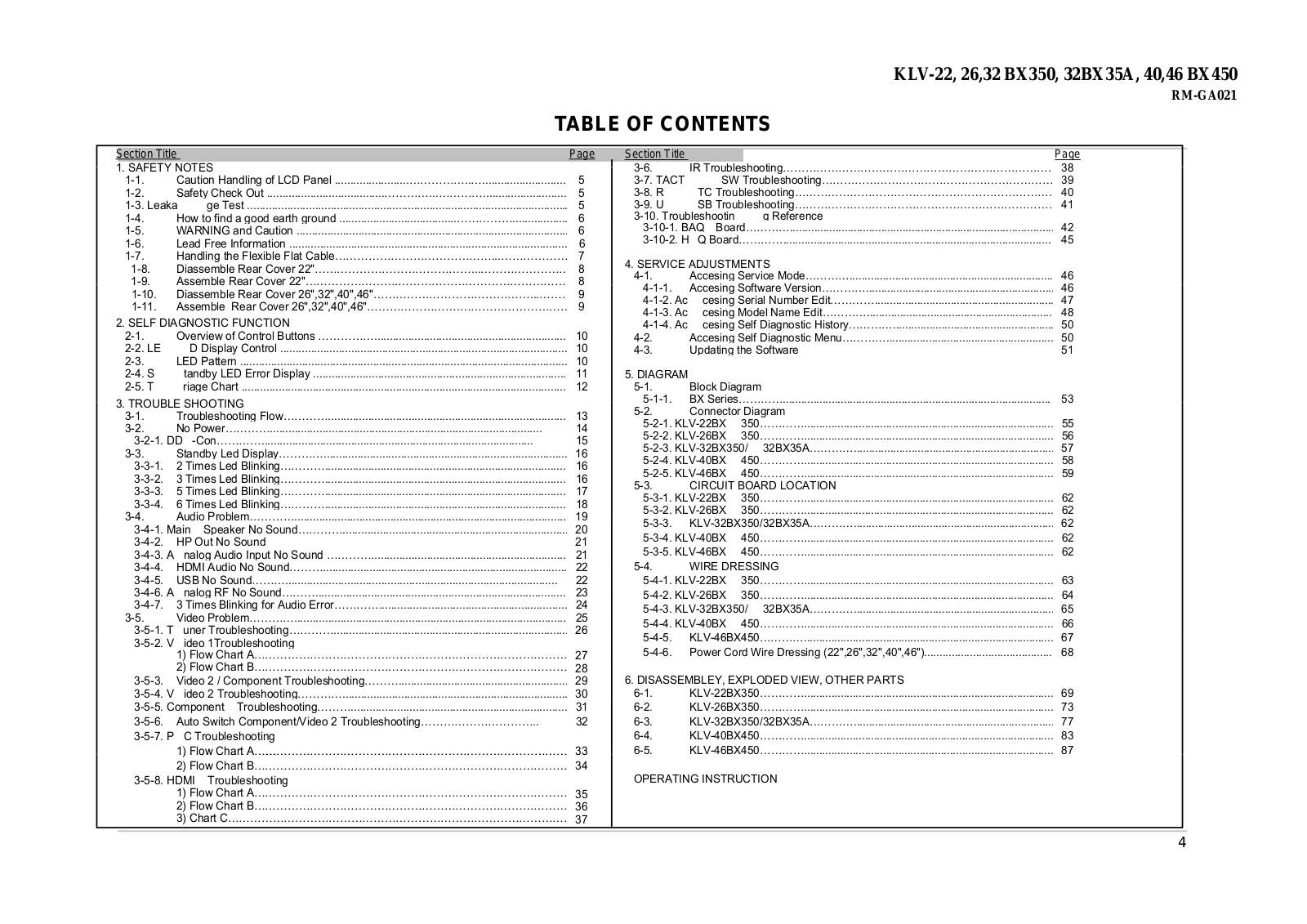
Table of contents
Loading...
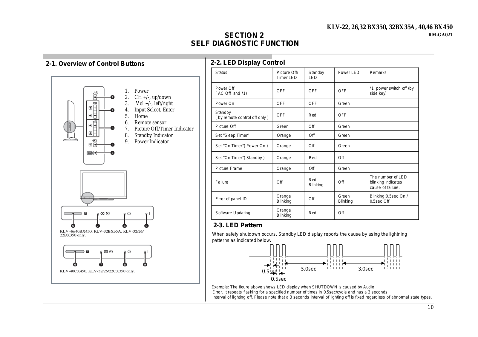
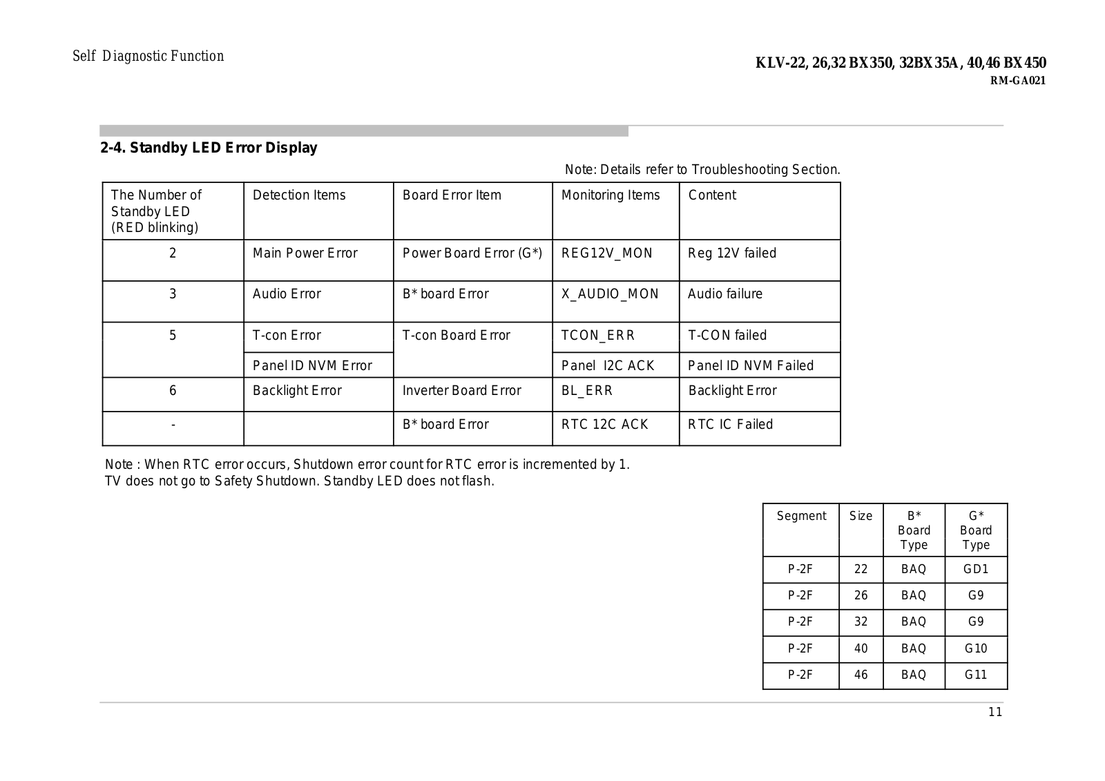
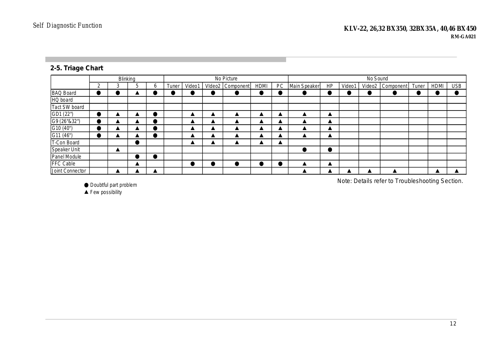
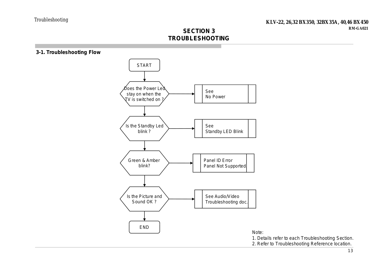
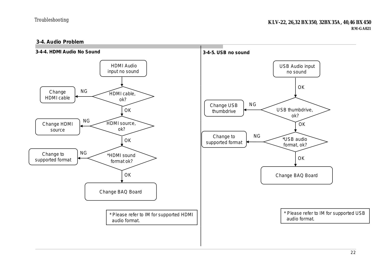
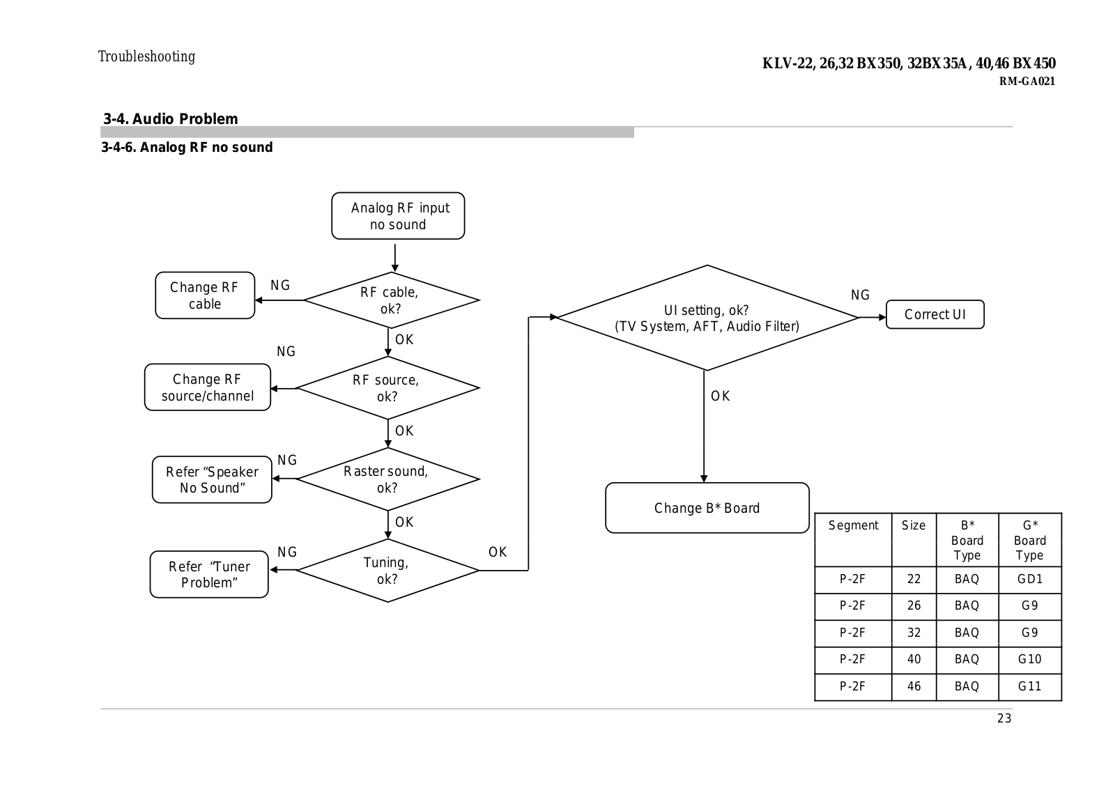
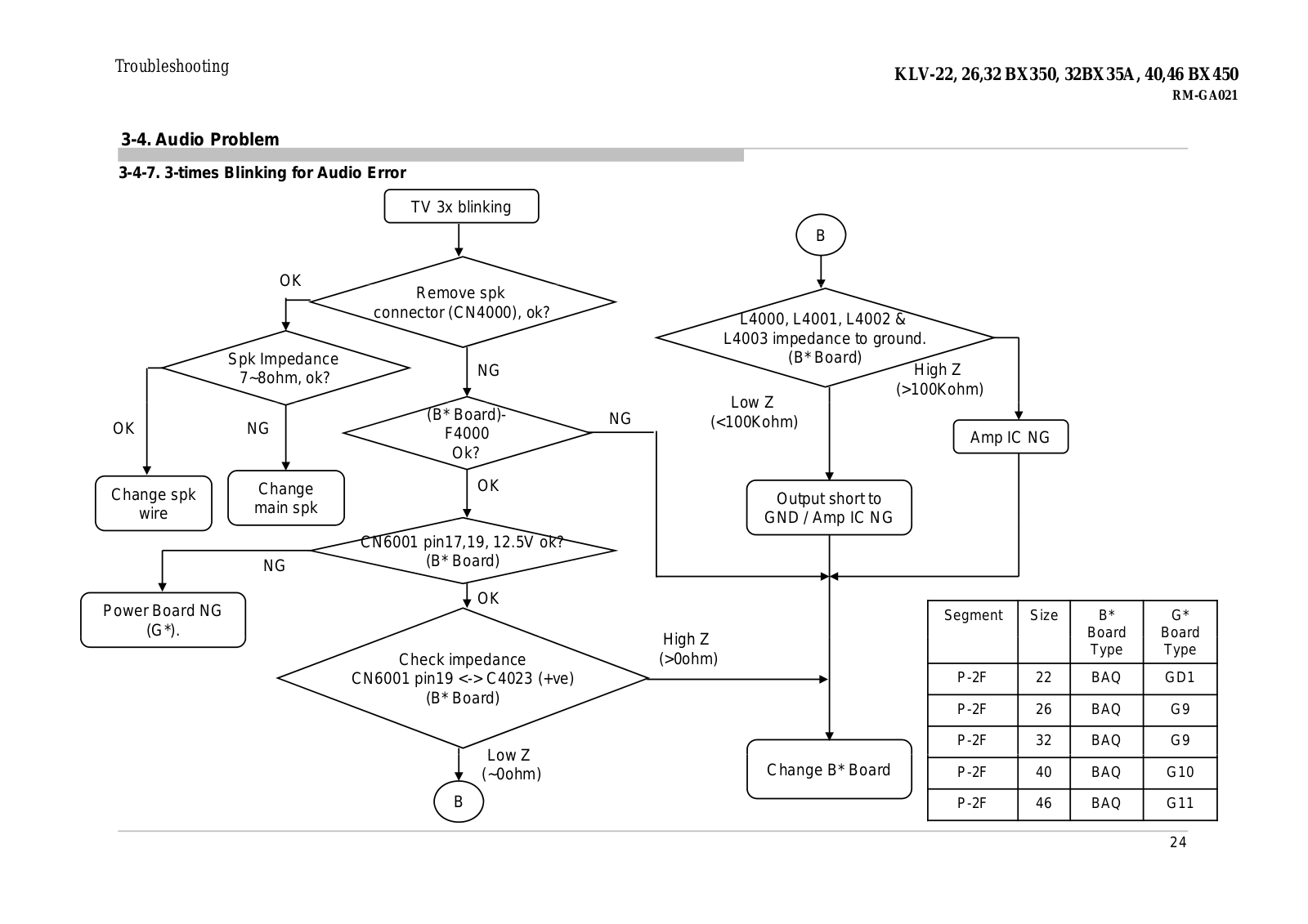
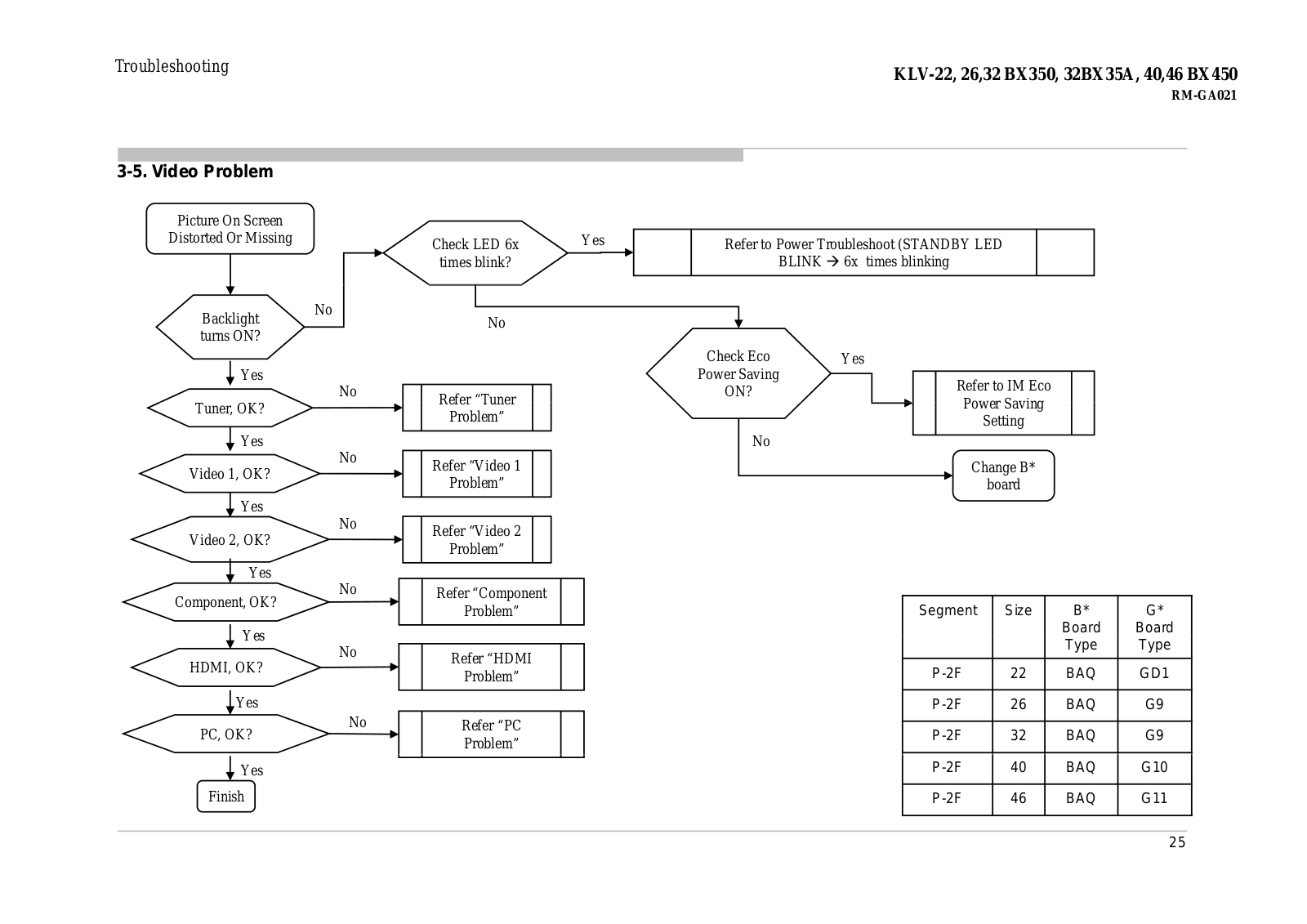
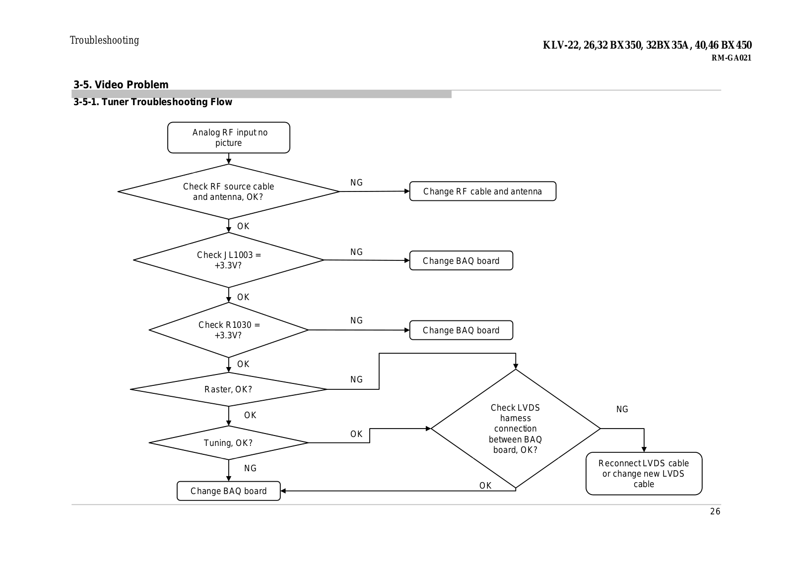
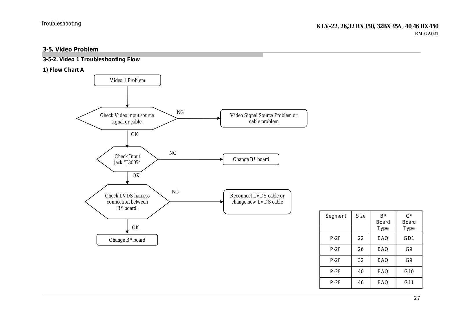
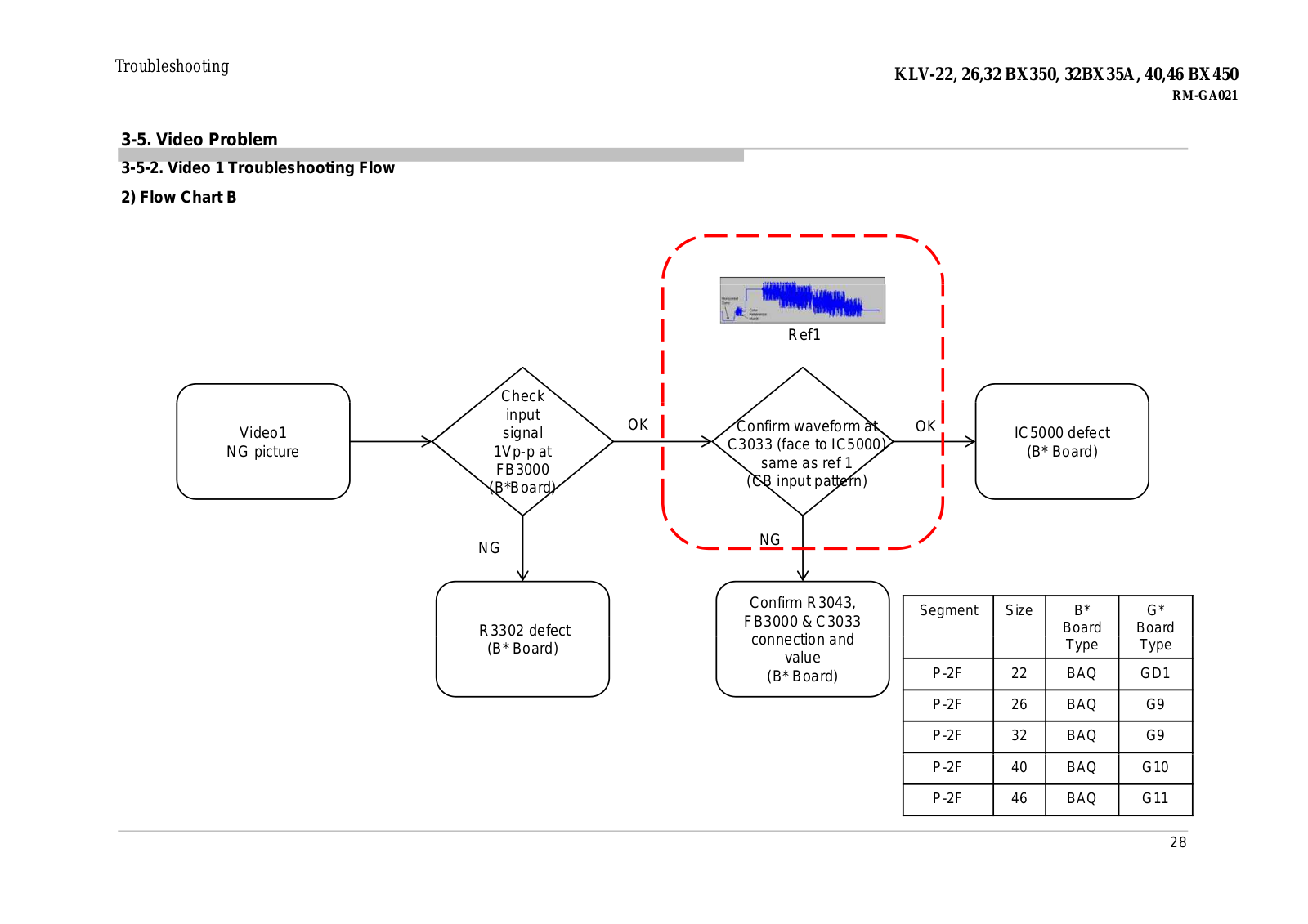
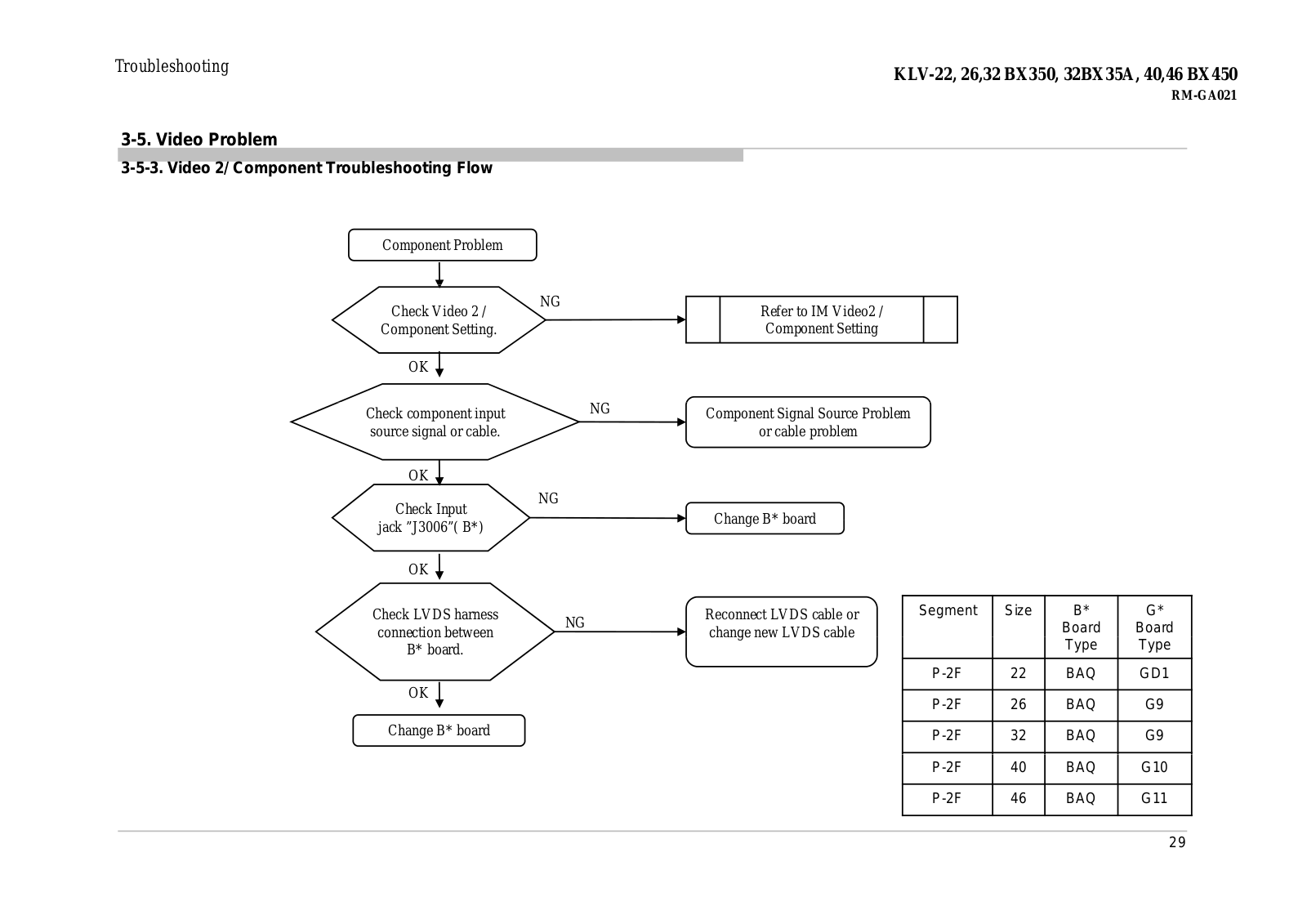
Sony KLV-22BX350 Schematic
...
Sony Schematic
Download
Specifications and Main Features
Frequently Asked Questions
User Manual
Download
Loading...
+
107
hidden pages
Unhide
You need points to download manuals.
1 point = 1 manual.
You can buy points or you can get point for every manual you upload.
Buy points
Upload your manuals
 Loading...