

Sony HVR-S270E,HVR-S270P Operating Manual

Digital HD Video Camera Recorder
Digital HD Video
Camera Recorder
Operating Guide
Before operating the unit, please read this manual thoroughly,
and retain it for future reference
3-280-852-12(1)
http://www.sony.net/
Printed on 70% or more recycled paper
using VOC (Volatile Organic Compound)
-free vegetable oil based ink.
Printed in Japan
GB
HVR-S270E/S270P
© 2008 Sony Corporation
Read this first
Before operating this unit, please read this
manual thoroughly, and retain it for future
reference.
Notes on use
Types of cassette you can use in your
camcorder
Your camcorder is capable of recording in
HDV, DVCAM and DV formats.
When recording in HDV/DV format, Sony
recommends that you use standard size DV
cassettes or mini DV cassettes.
When recording in DVCAM format, Sony
recommends that you use standard size
DVCAM cassettes or mini DVCAM
cassettes. Your camcorder does not support
the Cassette Memory function (
The HDV format
• Digital high-definition (HD) video signals
are recorded and played back on a DV
format cassette.
• HDV signals are compressed in MPEG2
format, which is adopted in BS (broadcast
satellite) digital and terrestrial digital
HDTV broadcastings and in Blu-ray disc
recorders.
p. 107).
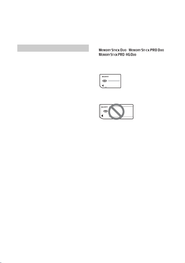
Types of “Memory Stick” you can use
in your camcorder
You can use any “Memory Stick” that has
the following markings.
“Memory Stick Duo”
(This size can be used with your
camcorder.)
“Memory Stick”
(You cannot use it in your camcorder.)
b Notes
• You cannot use any type of memory card
except “Memory Stick Duo.”
• “Memory Stick PRO Duo” can be used
only with “Memory Stick PRO”
compatible equipment.
• Do not attach a label or the like on a
“Memory Stick Duo” or a “Memory Stick
Duo” Adaptor.
• When using a “Memory Stick Duo” with
“Memory Stick” compatible equipment,
insert the “Memory Stick Duo” into the
“Memory Stick Duo” Adaptor.
2
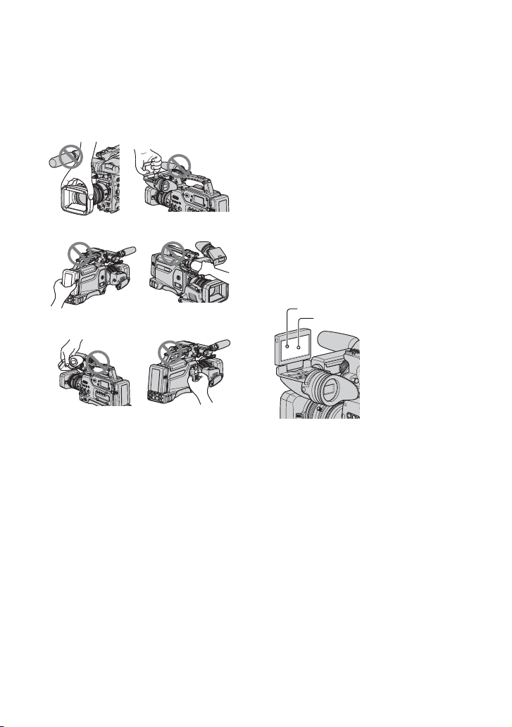
Using the camcorder
• Do not hold the camcorder by the
following part.
Lens hood
LCD panel
About menu items, LCD panel,
viewfinder, and lens
• A menu item that is grayed out is not
available under the current recording or
playback conditions.
• The LCD screen and the viewfinder are
manufactured using extremely highprecision technology, so over 99.99% of
the pixels are operational for effective
use. However, there may be some tiny
black points and/or bright points (white,
red, blue, or green in color) that appear
constantly on the LCD screen and the
viewfinder. These points are normal
results of the manufacturing process and
do not affect the recording in any way.
Battery pack
Viewfinder
b Notes
• The camcorder is not dustproof, dripproof
or waterproof.
See “About handling of your camcorder”
(p. 113).
• Do not connect cables to your camcorder
with their terminals placed the wrong
way. Squeezing the terminals into your
camcorder's jacks may damage them or
results in a malfunction of your
camcorder.
Microphone or
Microphone holder
Memory
Recording Unit
White, red, blue or green points
Black point
Do not expose your camcorder’s
viewfinder, lens, or LCD screen to the
sun or strong light source for extended
periods.
• Intense light sources, especially the sun
will converge on the viewfinder or lens
and damage the internal parts of your
camcorder. Avoid sunlight or other strong
light sources when storing your
camcorder. Protect this device by always
closing the lens cover or by placing it in
its bag when not in use.
On recording
• Before starting to record, test the
recording function to make sure the
picture and sound are recorded without
any problems.
Continued ,
3

Read this first (Continued)
• Compensation for the contents of
recordings cannot be provided, even if
recording or playback is not possible due
to a malfunction of the camcorder, storage
media, etc.
• TV color systems differ depending on the
countries/regions. To view your
recordings on a TV, you need a PAL
system-based TV.
• Television programs, films, video tapes,
and other materials may be copyrighted.
Unauthorized recording of such materials
may be contrary to the copyright laws.
• Because of the way that the image device
(CMOS sensor) reads out image signals,
the subjects passing by the frame rapidly
might appear crooked depending on the
recording conditions. This phenomenon
may be notable in displays having high
motion resolution.
• Because of the way that the image device
(CMOS sensor) reads out image signals,
the following phenomena may occur. The
phenomena can be reduced by adjusting
the shutter speed.
– Horizontal lines appear on the screen during
recording under fluorescent lights.
– Images on the screen look horizontally
divided when a subject is lighted with
flashlight.
On playing back HDV tapes on other
devices
A tape recorded in the HDV format cannot
be played back on a device that is not
compatible with the HDV format.
Check the contents of tapes by playing
them back on this camcorder prior to
playing them back on other devices.
Features available for the DV SP
format only.
The function that can be used when
i.LINK cable is connected.
The function that can be assigned to
an ASSIGN button.
About this manual
• The images of the LCD screen and the
viewfinder used in this manual for
illustration purposes are captured using a
digital still camera, and therefore may
appear different.
• The on-screen displays in each local
language are used for illustrating the
operating procedures. Change the screen
language before using your camcorder if
necessary (
• Design and specifications of recording
media and other accessories are subject to
change without notice.
p. 22).
About the Carl Zeiss lens
Your camcorder is equipped with a Carl
Zeiss lens, which was developed jointly by
Carl Zeiss, in Germany, and Sony
Corporation, and produces superior images.
It adopts the MTF measurement system for
video cameras and offers a quality typical
of a Carl Zeiss lens. Also, the lens for your
camcorder is T
unwanted reflections and faithfully
reproduce colors.
MTF= Modulation Transfer Function. The
number value indicates the amount of light
from a subject coming into the lens.
-coated to suppress
Notes on the icons used in this
manual
Features available for the HDV
format only.
Features available for the DVCAM
format only.
4

Table of Contents
Read this first ...........................................................................................2
Getting Started
Step 1: Checking supplied items ..............................................................8
Step 2: Attaching the supplied items ........................................................9
Step 3: Preparing a power supply ..........................................................16
Step 4: Turning the power on and holding your camcorder properly .....18
Step 5: Adjusting the viewfinder and LCD panel ....................................19
Step 6: Setting the date and time ...........................................................21
Step 7: Inserting a tape or a “Memory Stick Duo” ..................................23
Recording ..............................................................................................26
Changing the settings of your camcorder recordings .............................30
Assigning the functions to the ASSIGN buttons .....................................49
Using the Shot transition ........................................................................52
Marking focal point on the screen (Focus marking) ...............................55
Playback .................................................................................................56
Changing/checking the settings in your camcorder ................................59
Connecting a monitor or a TV ................................................................61
Changing the language setting .......................................................... 22
Recording/Playback
Adjusting the zoom ............................................................................. 30
Adjusting the focus manually.............................................................. 31
Adjusting the exposure ....................................................................... 33
Adjusting to natural color
(White balance)................................................................................... 35
Adjusting the black balance ............................................................... 37
Customizing the picture quality (Picture profile) ................................. 37
Adjusting the volume .......................................................................... 46
Recording an index signal .................................................................. 50
Reviewing the most recently recorded scenes (Rec review).............. 51
Searching for the last scene of the most recent recording
(End search) ....................................................................................... 51
Playing back the most recently recorded movies
(Last scene review)............................................................................. 51
Changing the screen .......................................................................... 59
Displaying recording data (Data code) .............................................. 59
Displaying the settings in your camcorder (Status check) ................. 60
Continued ,
5

Table of Contents (Continued)
Using the Menu
Using the menu items ........................................................... 63
Menu items ............................................................................................65
(CAMERA SET) menu ....................................................................68
Settings to adjust your camcorder to the recording conditions (GAIN SETUP/
BACK LIGHT/STEADYSHOT, etc.)
(AUDIO SET) menu ........................................................................ 75
Settings for the audio recording (HDV 2CH/4CH/XLR SET, etc.)
(DISPLAY SET) menu ....................................................................77
Display settings of the display and the viewfinder (MARKER/VF B.LIGHT/DISP
OUTPUT, etc.)
(IN/OUT REC) menu ......................................................................81
Recording settings, input and output settings (REC FORMAT/HDV PROGRE./
VIDEO OUT/EXT REC CTRL, etc.)
(TC/UB SET) menu ....................................................................... 85
(TC PRESET/UB PRESET/TC LINK, etc.)
(MEMORY SET) menu ....................................................................87
Settings for the “Memory Stick Duo” (ALL ERASE/FORMAT, etc.)
(OTHERS) menu ............................................................................ 89
Settings while recording on a tape or other basic settings (QUICK REC/BEEP,
etc.)
Dubbing/Editing
Recording pictures from a VCR ............................................................92
Copying movies on a tape to a computer .............................................. 94
Troubleshooting
Troubleshooting .....................................................................................97
Warning indicators and messages ....................................................... 106
6

Additional Information
Maintenance and precautions ..............................................................107
Specifications .......................................................................................117
HDV format and recording/playback ................................................ 107
Compatibility of the DVCAM/DV formats ........................................... 108
About the “Memory Stick” ................................................................. 110
About i.LINK...................................................................................... 111
About x.v.Color ................................................................................. 112
About handling of your camcorder ................................................... 113
Quick Reference
Identifying parts and controls ...............................................................121
Indicators for the LCD screen and viewfinder ......................................128
Index .....................................................................................................132
7
Getting Started
Step 1: Checking supplied items
Make sure that you have following items
supplied with your camcorder.
The number in the parentheses indicates the
number of that item supplied.
• A cassette tape and a “Memory Stick Duo” are
not included. See pages
of cassette tape and “Memory Stick Duo” that
you can use on your camcorder.
Carl Zeiss lens (VCL-412BWS) (1) (p. 9)
This lens is pre-mounted.
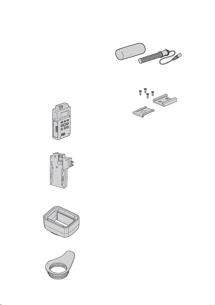
Memory Recording Unit (HVR-MRC1) (1)
p. 14),
(
i.LINK Cradle (HVRA-CR1) (1) (p. 15)
Lens hood with lens cover (1) (p. 13)
This lens hood is pre-mounted.
2, 107 and 110 for types
Wind Screen (1), Microphone (ECM-XM1)
p. 12)
(1) (
Accessory shoe kit (Accessory shoe (1),
Accessory shoe plate (1), screws (4))
p. 121)
(
Shoulder belt (1) (p. 13)
Lens mount cap (1) (p. 127),
Rear lens cap (1) (p. 127)
Test chart for flange focal length
adjustment (1) (
CD-ROM “Manuals for Digital HD Video
Camera Recorder” (1)
Operating Guide (This manual) (1)
p. 10)
Large eyecup (1) (p. 19)
8
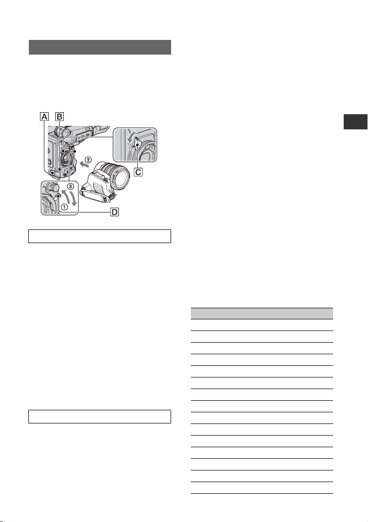
Step 2: Attaching the supplied items
Mounting the lens
Make sure to turn off the POWER switch of
your camcorder before mounting the lens.
Refer to the manuals provided with the lens
for details on the proper handling of the
lens.
Mounting the Carl Zeiss lens
1 Push the lens locking lever D up and
remove the lens or the lens mount cap
from the lens mount.
2 Align the center slot in the lens mount
with the center pin on the lens, and
insert the lens into the mount.
3 While holding the lens in place, push
the lens locking lever D down to
mount the lens.
b Notes
• If the lens is not properly locked, it may come
off when in use, which may cause a serious
problem. Make sure that the lens is securely
locked. Sony recommends that you set the lens
securing tab C as illustrated.
Mounting non-Carl Zeiss lens
1 Push the lens locking lever D up and
remove the lens or the lens mount cap
from the lens mount.
2 Align the center slot in the lens mount
with the center pin on the lens, and
insert the lens into the mount.
3 While holding the lens in place, push
the lens locking lever D down to
mount the lens.
4 Connect the lens cable to the LENS jack
A.
5 Push the lens cable in the cable holder
B.
b Notes
• Use a lens mount adaptor suitable for your lens.
– 1/3" bayonet mount lens
You can mount the lens without an adaptor.
– 2/3" bayonet mount lens
Use a Fujinon ACM-17.
A focal length is twice as that without the
adaptor.
– 1/2" bayonet mount lens
Use a Fujinon ACM-12.
A focal length is 1.3 times as that without the
adaptor.
– SONY 1/2" bayonet mount lens
Use a Fujinon ACM-19.
A focal length is 1.3 times as that without the
adaptor.
Your lens performance is not guaranteed.
• When you mount a lens other than a Carl Zeiss
lens, you cannot use the following menu items.
Even you set those menu items, the settings do
not take effect.
For the lens with the lens cable (12 Pin)
AF ASSIST
ASSIGN BTN
CAMERA
ASSIGN#
FOCUS
FOCUS INFNTY
FOCUS MACRO
ONE PUSH AF
ASSIGN BTN
LENS
L1
L2
FLANGE BACK
FOCUS DISP
FOCUS MACRO
Continued ,
Getting Started
9

Step 2: Attaching the supplied items (Continued)
For the lens with the lens cable (12 Pin)
HANDLE ZOOM
SHOT TRANSITION
STEADYSHOT
S.TRANS/F.MARK
ZOOM DISPLAY*
Extender indicator**
# shows the ASSIGN BTN number.
* If your lens does not have a zoom display
function, the zoom position is not displayed on
the screen.
**Your camcorder does not display the extender
indicator when you use the extender function of
the lens.
For the lens without the lens cable (12 Pin)
AF ASSIST
ASSIGN BTN
CAMERA
ASSIGN#
FOCUS
FOCUS INFNTY
FOCUS MACRO
ONE PUSH AF
ASSIGN BTN
LENS
L1
L2
RET
AT IRIS LMT
CAM DATA DSP (Iris value)
FLANGE BACK
FOCUS DISP
FOCUS MACRO
HANDLE ZOOM
SHOT TRANSITION
STEADYSHOT
S.TRANS/F.MARK
ZOOM DISPLAY
# shows the ASSIGN BTN number.
10
• If the lens is not properly locked, it may come
off when in use, which may cause a serious
problem. Make sure that the lens is securely
locked. Sony recommends that you set the lens
securing tab C as illustrated.
• Press the REC START/STOP button on the
handle to record when using a lens that does not
have a lens cable.
z Tips
• When you attach a non-Carl Zeiss lens, Sony
recommends that you adjust the black balance
with the iris closed before recording. (
p. 37)
Adjusting the flange focal length (for
Carl Zeiss lens)
You need to adjust the flange focal length
(the distance from the lens flange to the
plane of the image along the optical axis)
when you have changed lenses.
z Tips
• Your camcorder can store flange focal length
data for ten different Carl Zeiss lenses (VCL412BWS/VCL-308BWS. If you remount the
lens after you have mounted ten different lenses
and adjusted their flange focal length, you need
to adjust the flange focal length for the lens even
for the Carl Zeiss lens whose flange focal length
has been adjusted.
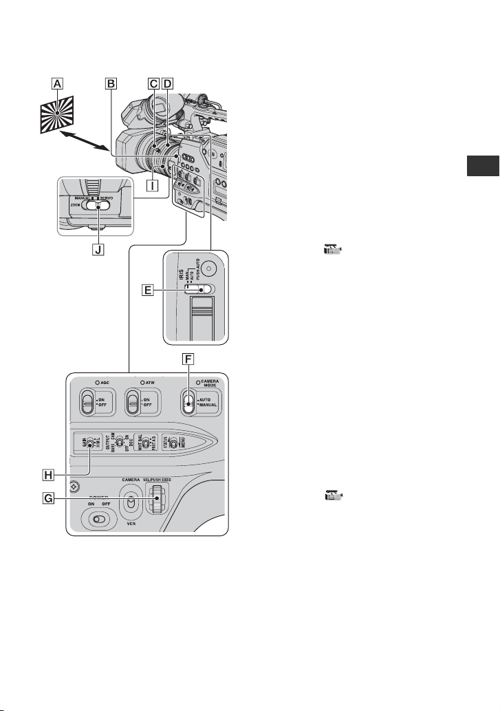
Adjusting the flange focal length
T
automatically
1 Set the CAMERA MODE switch F to
MANUAL.
2 Set the IRIS switch E to MAN.
3
Set the gain to 0dB with the gain switch H.
If you have not changed the gain switch
setting from the default, set the gain
switch H to L.
Make sure that the AGC switch is set to
OFF.
4 Set the shutter speed to automatic
adjustment mode
5 Fully open the aperture with the iris ring
I.
6 Place the flange focal length adjustment
test chart A about 2-3 meters (7-10
feet) away.
Adjust the lighting or the ND filter B
so that a subject is properly lighted.
7 Set the ZOOM switch J to SERVO.
8
Select [AUTO ADJUST] in [FLANGE
BACK] of
(p. 74)
.
9 Select [YES] with the SEL/PUSH
EXEC dial G.
The flange focal length adjustment starts
and [EXECUTING] appears on the screen.
When the adjustment is completed,
[Completed.] appears on the screen.
If the adjustment fails, [Could not adjust.]
appears on the screen. Try the adjustment
again.
(p. 35).
(CAMERA SET) menu
Adjusting the flange focal length
manually
1 Perform steps 1 through 4 of
"Adjusting the flange focal length
automatically."
2 Set the ZOOM switch J to MANUAL.
3 Select [MANU ADJUST] in [FLANGE
BACK] of
4 Select [YES] with the SEL/PUSH
EXEC dial G.
5 Turn the zoom ring D fully to the
telephoto side.
6 Turn the focus ring C until the subject
comes in focus, then press the SEL/
PUSH EXEC dial G.
7 Turn the zoom ring D fully to the wide
angle side.
8 Turn the focus ring C until the subject
comes in focus, then press the SEL/
PUSH EXEC dial G.
(CAMERA SET) menu.
Continued ,
Getting Started
11
REC CH SELECT
2CH MODE
IN1
CH1 CH2
IN2
IN4
IN3
Step 2: Attaching the supplied items (Continued)
When the adjustment is completed,
[Completed.] appears on the screen.
If the adjustment fails, [Could not adjust.]
appears on the screen. Try the adjustment again.
z Tips
• You can check the focusing easily if you do the
following before adjusting the focal length.
– Set the PEAKING switch to ON (p. 32).
– Press the ASSIGN button to which
[EXP.FOCUS] is assigned (p. 49).
• If the adjustment fails, confirm the following.
– A bright subject is not within the view.
– The ND filter switch does not stop at halfway
between two positions.
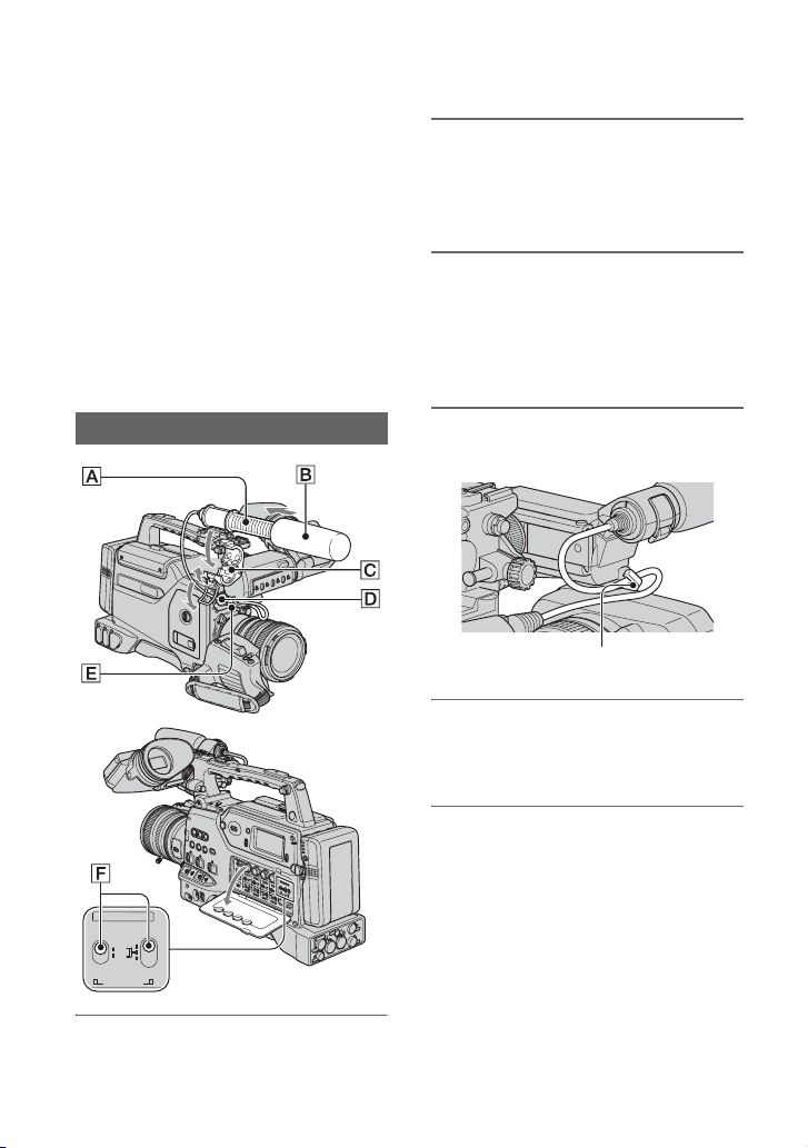
2 Place the microphone A in the
microphone holder C with the
model name facing upward, close
the cover, and shut the clamp.
3 Connect the plug of the
microphone to the AUDIO INPUT1
(L) jack D.
Push the plug in the jack until it is
securely locked.
12
Attaching the supplied microphone
1 Attach the wind screen B to the
supplied microphone A.
4 Put the microphone cable into the
cable holder E.
Put the cable in the outer cable holder.
5 Select the channel with the REC
CH SELECT switch F.
See p. 46 for details.
z Tips
• See page 46 for adjusting the volume.
• Set the INPUT1/2/3/4 switch for the jack
connected to the microphone to MIC+48V.
• When you connect a device that supports the
+48V power source to any of the INPUT jacks,
set the respective INPUT switch to MIC prior to
connecting the device. When you disconnect the
device, set the respective INPUT switch to MIC
first, then disconnect it.
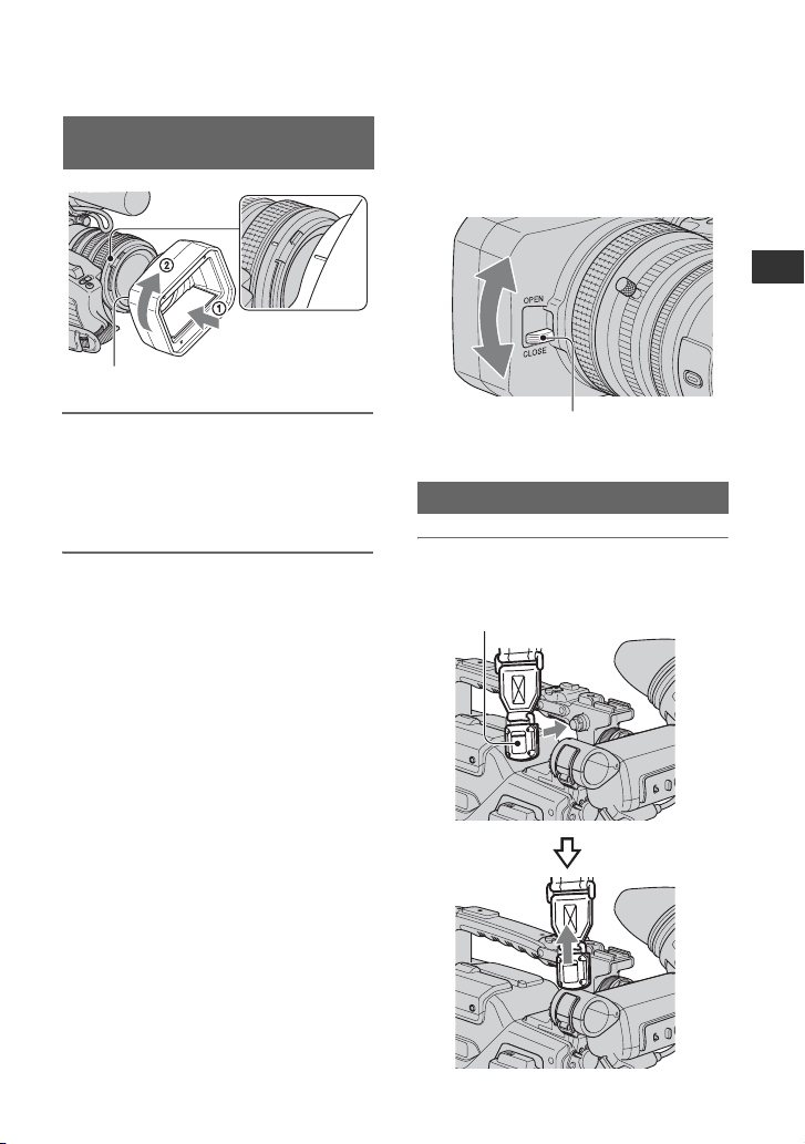
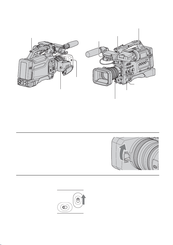
Attaching the lens hood with lens
Cli
cover
PUSH (lens hood release) button
Align the marks on the lens hood to
those on the camcorder, and turn the
lens hood in the direction of the
arrow 2.
To remove the Lens hood with lens
cover
Turn the lens hood in the opposite direction
to the arrow 2 in the illustration while
pressing the PUSH (lens hood release)
button.
z Tips
• If you attach or remove a 72mm (2 7/8 in.) PL
filter or MC protector, remove the lens hood
with lens cover.
To open or close the shutter of the
Lens hood with lens cover
Move the lens cover lever up or down to
open or close the lens cover.
Getting Started
Move the lens cover lever to OPEN to
open the lens cover, and move the lever
to CLOSE to close the lens cover.
Attaching the shoulder strap
1 Fit one of the clips to a shoulder
strap fitting.
p
Pull up the strap to lock the fitting.
Continued ,
13
Step 2: Attaching the supplied items (Continued)
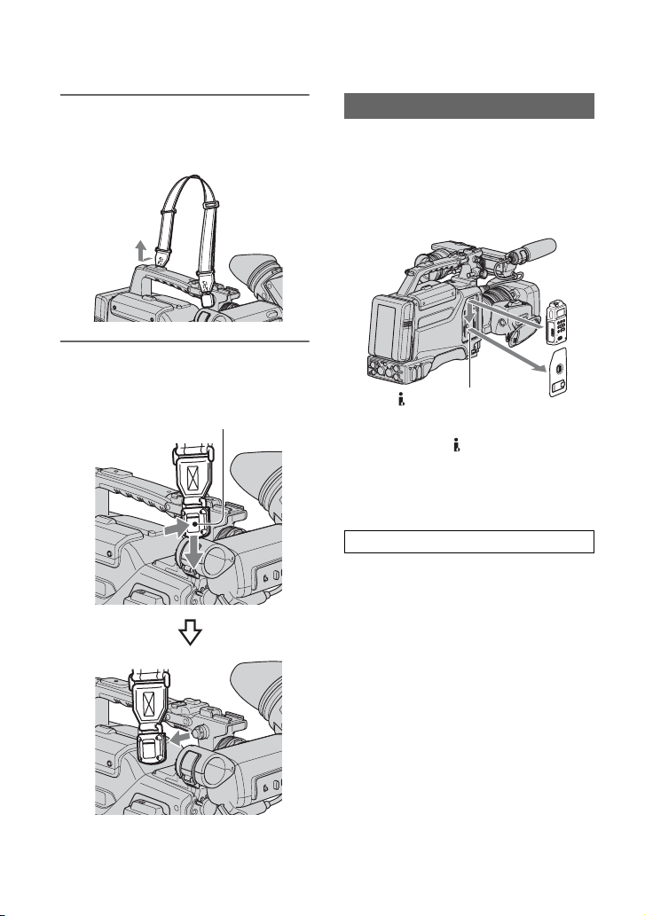
2 Fit the other clip to the shoulder
strap fitting on the other side of
the grip in the same way.
To remove the shoulder strap
Pull in the direction of the
arrow while pressing here.
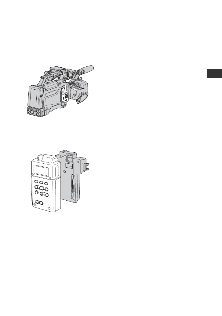
Attaching Memory Recording Unit
Attach the Memory Recording Unit to your
camcorder as illustrated after inserting your
CompactFlash Card into it.
For details, refer to the Operating
Instructions of the Memory Recording Unit
on the CD-ROM.
HDV/DV jack (6-pin)
b Notes
• You cannot use the HDV/DV jack when the
Memory Recording Unit is attached to your
camcorder.
• We recommend using Sony CompactFlash
Cards with your Memory Recording Unit.
Using non-Sony CompactFlash Cards
When you use non-Sony CompactFlash
Cards, data may be recorded incorrectly.
When you use non-Sony CompactFlash
Cards, we recommend that you test them
beforehand as follows.
1 Format the CompactFlash Card with the
Memory Recording Unit.
2 Record at least 20 clips of about 10
seconds each in HDV recording mode.
3 If you have nonlinear editing software,
load the files into it and check whether
you can edit the data correctly.
14
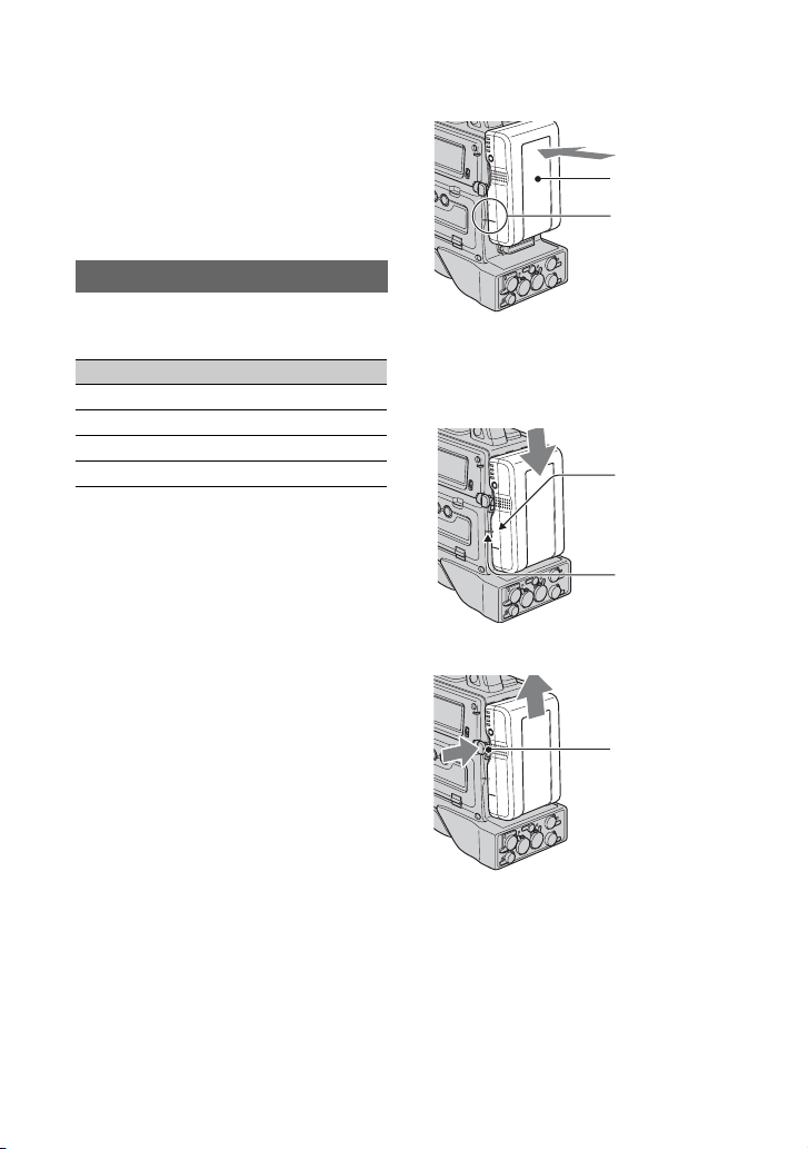
To remove the Memory Recording
Unit
Slide the unit upward while pushing the
RELEASE lever of the Memory Recording
Unit downward.
To attach the Memory Recording Unit
to the i.LINK Cradle
Attach the Memory Recording Unit to the
i.LINK Cradle as illustrated.
Getting Started
To remove the Memory Recording
Unit from the i.LINK Cradle
Slide the unit upward while pushing the
RELEASE lever of the Memory Recording
Unit downward.
z Tips
• Refer to the operating instructions of HVRMRC1 on the supplied CD-ROM for details on
the i.LINK Cradle.
15
Step 3: Preparing a power supply
The following power supplies are
recommended for your camcorder.
• BP-GL65/GL95/L60S/L80S Lithium-ion
Battery Pack
• AC power using the AC-550, AC-DN2,
AC-DN10 AC Adaptor
Using a battery pack
Approximate operating time (min.) when
you use a fully charged battery pack.
LOCK
Back of the camcorder
Battery pack
Align these lines.
Model name HDV DVCAM (DV)
BP-GL65 240 255
BP-GL95 370 385
BP-L60S 215 230
BP-L80S 295 310
Before use, charge the battery pack with a
charger suitable for each battery.
• All times are measured under following
conditions.
– when recording on both tape and Memory
Recording Unit (HVR-MRC1)
– when using the microphone (ECM-XM1)
– when recording continuously
– when using the viewfinder with the LCD
panel closed
• For details on charging procedure, refer to the
battery charger operation manual.
b Notes
• A warm battery pack may not be able to be fully
recharged.
• When you set [BATTERY TYPE] appropriately
for your battery, approximate remaining battery
capacity is displayed on the screen. The
displayed approximate remaining battery
capacity may slightly differ from that indicated
by the indicator on your battery (
p. 91).
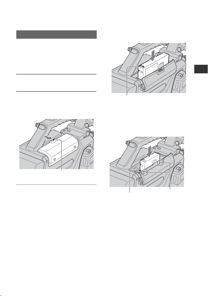
To attach the battery pack
1 Press the battery pack against the back
of the camcorder, aligning the line on
the side of the battery pack with the
matching line on the camcorder.
2 Slide the battery pack down until its
“LOCK” arrow points at the matching
line on the camcorder.
“LOCK” arrow
LOCK
Line on the
camcorder
To detach the battery pack
Holding the
LOCK
b Notes
• During recording, playback, and loading/
unloading a tape, be careful never to remove the
battery pack.
• Make sure to turn the camcorder off before
changing the battery (except when using an AC550 and an AC-DN2/DN10 AC Adaptor
together).
button in, pull
the battery pack
up.
16

Using an AC Adaptor
To use the AC-550 AC Adaptor
Connect the camcorder to the AC power
supply through an AC-550 AC Adaptor as
shown in the following figure, and turn the
POWER switch of the AC-550 on.
to an AC power
source
L
O
C
K
DC IN 12V
AC
Adaptor
AC-550
DC output cable
(supplied with the
AC-550)
DC OUT
Power switch on
To use the AC-DN10 AC Adaptor
Mount an AC-DN10 on the camcorder in
the same way as a battery pack, then
connect to the AC power supply.
The AC-DN10 can supply up to 100 W of
power.
2 Connect an AC-550 AC Adaptor to an
AC power source, then connect it to the
DC IN 12V connector of the camcorder
p. 17).
(
The power source switches
automatically from the battery pack to
the AC Adaptor connected to the DC IN
12V connector.
b Notes
• There may be some noise on the video
signal at the time of power source
switching.
3 Replace the battery pack with a fully
charged one.
Getting Started
to an AC
power
source
Avoiding breaks in operation due
to an exhausted battery
When the battery pack is becoming
exhausted, you can perform battery
replacement without causing a break to the
camcorder operation by using an AC
Adaptor.
1 Turn the AC-550 AC Adaptor on.
17
Step 4: Turning the power on and holding your
camcorder properly
To record or play, set the CAMERA/VCR
switch to respective positions.
When you use your camcorder for the first
time, [CLOCK SET] screen appears (
POWER switch
CAMERA/VCR switch
p. 21).
L
O
C
K
1 Set the POWER switch to ON, and
set the CAMERA/VCR switch.
CAMERA
POWER
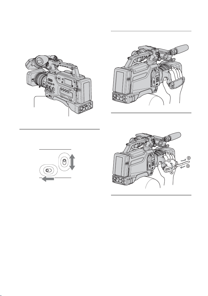
ON OFF
VCR
2 Hold the camcorder properly.
3 Ensure a good grip, then fasten
the grip belt.
CAMERA: To record pictures.
VCR: To play or edit pictures.
b Notes
• The current date and time appears on the LCD
screen for a few seconds when you turn on your
camcorder once you set the date and time
([CLOCK SET],
p. 21).
18
To turn off the power
Set the POWER switch to OFF.
b Notes
• If warning messages appear on the screen,
follow the instructions.
Step 5: Adjusting the viewfinder and LCD panel
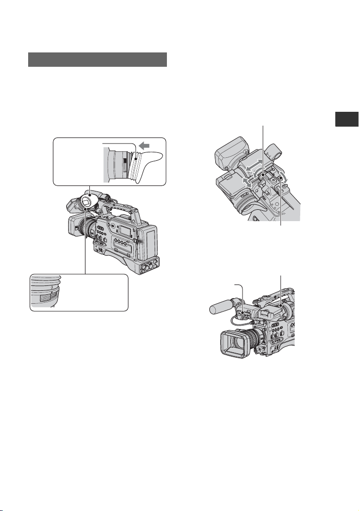
The viewfinder
To attach the large eyecup
To attach the supplied large eyecup, stretch
it slightly and align it with the eyecup
groove in the viewfinder. You can attach
the large eyecup facing either the right or
left side.
Large eyecup
(supplied)
LO
C
K
Align the protrusion
on the eyecup with
the mark on the eye
piece.
To adjust the viewfinder position
To adjust the viewfinder left-to-right
position, loosen the left-to-right fixing ring.
To adjust the front-to-back position, loosen
the front-to-back position locking knob.
Viewfinder left-to-right
position fixing ring
Viewfinder front-to-back
position locking knob
Eyepiece
focusing knob
PEAKING
switch
Getting Started
To adjust the eyepiece focus
First focus the image with the lens, then
adjust the viewfinder lens adjustment lever
to get the clearest viewfinder image for
your eyesight.
To adjust the image detail
Set the PEAKING switch to ON.
The detail of the viewfinder image is
enhanced, which helps you to focus the
image.
19

MEMORY
DELETE
DISPLAY LCD BRIGHT
INDEX
-
+
-
+
PLAY
1
Step 5: Adjusting the viewfinder and LCD panel (Continued)
To adjust the brightness
Set the brightness in [VF B.LIGHT] of
(DISPLAY SET) menu (p. 80).
b Notes
• You may see primary colors shimmering in the
viewfinder when you move your eye line. This
is not a malfunction. The shimmering colors
will not be recorded on the recording media.
b Notes
• When you set the VIDEO OUT switch to LCD,
video signals cannot be output from the VIDEO
OUT jack or S VIDEO jack. To output the video
signals from the VIDEO OUT jack or S VIDEO
jack, set the VIDEO OUT switch to
COMPOSITE. With this setting, images are not
displayed on the screen.
z Tips
• You can use the LCD panel for recording mirror
The LCD panel
Set the VIDEO
OUT switch to
LCD.
image. You will see a mirror image on the LCD
screen but the image will be recorded in a
normal image.
• Because the LCD panel on your camcorder is a
full-screen display, bottom of the screen may
look distorted, such as horizontal lines on the
screen. This does not affect on your images
recorded on your CompactFlash Card or tape.
To adjust the brightness
180 degrees (max.)
2180
degrees
(max.)
290
degrees
(max.)
Adjust the LCD brightness with the - LCD
BRIGHT + buttons. You can turns on and
off the LCD backlight by pressing the
DISPLAY button.
20
DISPLAY button
- LCD BRIGHT +
buttons
Step 6: Setting the date and time
CAMERA
VCR
POWER
GAIN
OUTPUT
DCC
WHT BAL
BARS CAM
PRST A B
STATUS
MENU
OFF ON
H M L
ON OFF
SEL/PUSH EXEC
Set the date and time when using this
camcorder for the first time. If you do not
set the date and time, [CLOCK SET] screen
appears every time you turn on your
camcorder or change the CAMERA/VCR
switch position.
z Tips
• If you do not use your camcorder for about 3
months, the built-in rechargeable battery gets
discharged and the date and time settings may
be cleared from the memory. In that case,
charge the rechargeable battery and then set the
date and time again (p. 115).
L
O
C
K
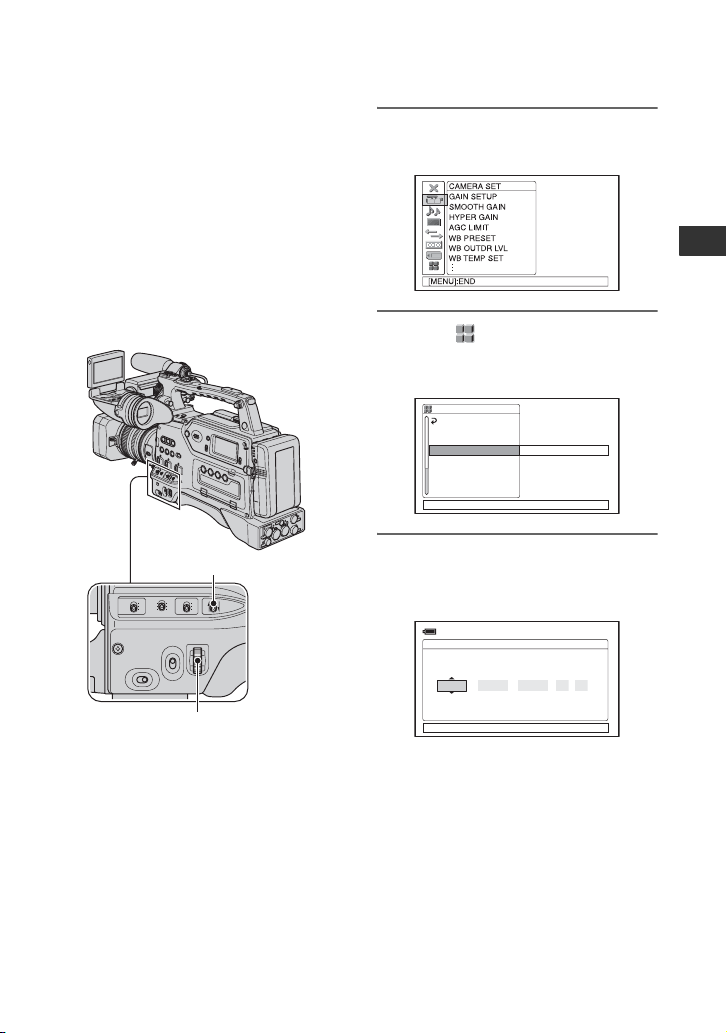
1 Push the MENU/STATUS switch
to MENU.
2 Select (OTHERS) by turning
the SEL/PUSH EXEC dial, then
press the dial.
OTHERS
RETURN
CAMERA PROF.
ASSIGN BTN
CLOCK SET
WORLD TIME
LANGUAGE
QUICK REC
DATE REC
[MENU]: END
Getting Started
--:--:--
MENU/STATUS switch
SEL/PUSH EXEC dial
Skip to step 4 when you set the clock for
the first time.
3 Select [CLOCK SET] by turning
the SEL/PUSH EXEC dial, then
press the dial.
CLOCK SET
MDY
--
2008
[MENU]: CANCEL
--:--:--:--
0 : 00 11
Continued ,
21
Step 6: Setting the date and time (Continued)
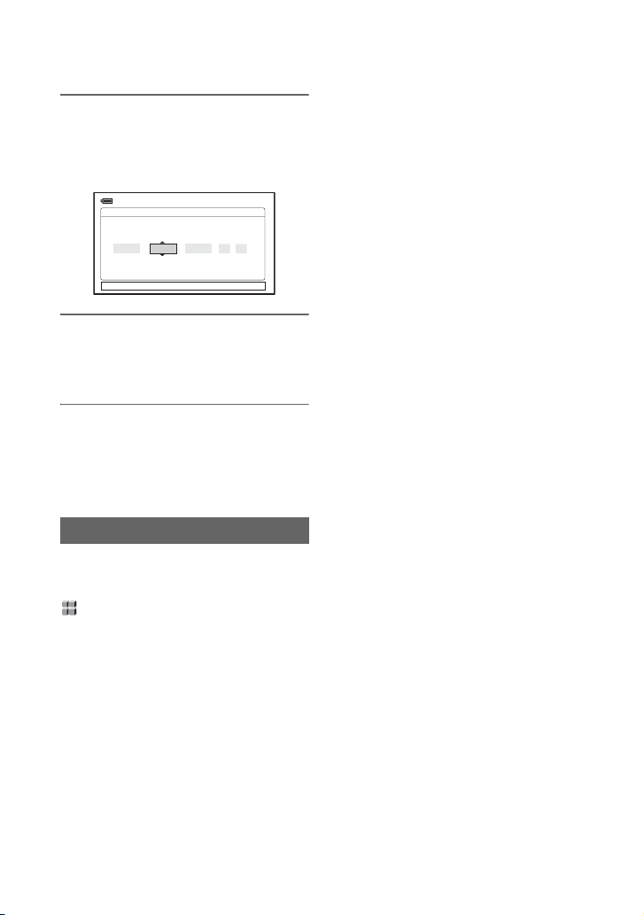
4
Set [Y] (year) by turning the SEL/
PUSH EXEC dial, then press the dial.
You can set any year up to the year
2079.
CLOCK SET
MDY
--
2008
[MENU]: CANCEL
--:--:--:--
0 : 00 11
5 Set [M] (month), [D] (day), hour
and minute, then press the dial.
The clock starts.
z Tips
• The date and time are automatically recorded on
the tape, and can be displayed during playback
(DATA CODE button, p. 59).
.
Changing the language setting
You can change the on-screen displays to
show messages in a specified language.
Press the MENU button to select the
(OTHERS) with the SEL/PUSH EXEC
dial.
Select the screen language in
[LANGUAGE] (p. 90).
22
Step 7: Inserting a tape or a “Memory Stick Duo”
P
Cassette tape
The camcorder can use standard-size and
mini-size DVCAM/DV cassettes. For
details about usable cassette, see
cassette you can use in your camcorder” on
page 2.
“Types of
1 Set the POWER switch to ON.
2 While sliding the open lever in the
direction of the arrow, open the
cassette lid.
Open lever
3 Insert the cassette with the
cassette window (on the front)
facing outward and the REC/
SAVE switch facing upward.
Check for tape slack before inserting the
cassette.
ress the center of
the cassette.
REC/SAVE switch
To insert a mini-size cassette
Insert the cassette with the cassette window
(on the front) facing outward. Push the
cassette between the both guides.
Guides
Mini-size cassette
match marks
Getting Started
Continued ,
23
Step 7: Inserting a tape or a “Memory Stick Duo” (Continued)
• If a cassette is not inserted completely or gets
4 Close the cassette lid until it
clicks.
Top of the lid
stuck when being inserting, take out the cassette
and reinsert it. If your insert a cassette forcibly,
the cassette may not be inserted in the correct
position or may cause a malfunction.
• When inserting a cassette, hold the center of the
cassette and insert it straight toward the
compartment. Holding the side of the cassette
may cause it to be inserted incorrectly.
• When inserting a cassette, put the camcorder on
a horizontal and stable surface.
• When inserting a mini DV cassette tape, strong
light entering the slot may cause a malfunction
such as improper cassette type detection.
“Memory Stick Duo”
Press the lid firmly until it clicks.
If the cassette lid is hard to close,
press the top of the lid.
You can use only a “Memory Stick Duo”
marked with
or
(p. 110).
To eject a cassette
Follow the procedure above, and take out
the cassette by pressing the Z (eject) button
in step 3.
Z (eject) button
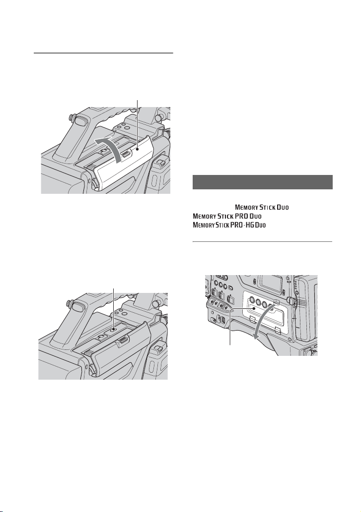
1 Open the audio control panel
cover.
,
b Notes
• Before inserting a cassette, make sure that there
is no cassette in the cassette compartment.
Inserting two cassettes by mistake may cause a
malfunction.
• Internal parts of the camcorder may become
bent or otherwise damaged if you attempt to
insert a mini-size cassette in the wrong direction
(such as with the cassette turned backside front
so the reel holes face the cassette holder window
or with the cassette turned sideways so that a
short side enters first).
24
Audio control
panel cover
L
O
C
K
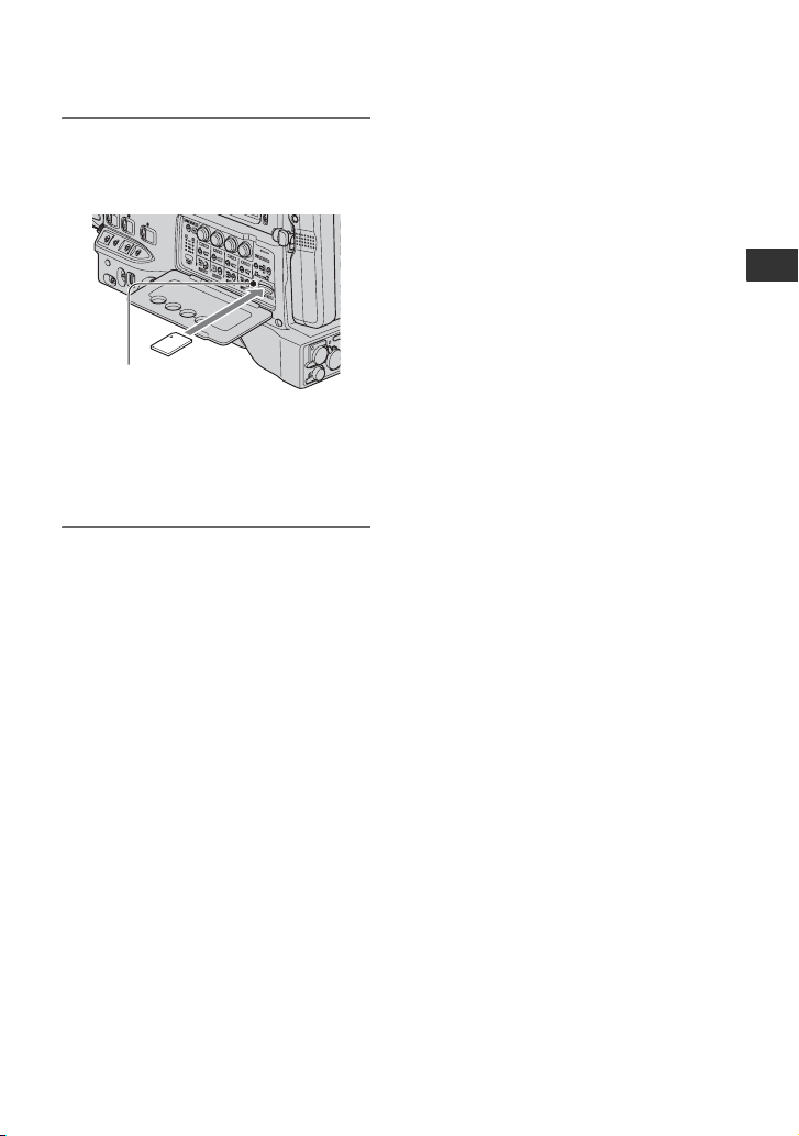
2 Insert the “Memory Stick Duo”
into the “Memory Stick Duo” slot
in the right direction until it clicks.
Access lamp
b Notes
• If you insert the “Memory Stick Duo” into
the slot in the wrong direction, the “ Memory
Stick Duo,” the “Memory Stick Duo” slot,
or image data may be damaged.
To eject a “Memory Stick Duo”
Lightly push the “Memory Stick Duo”
once.
b Notes
• When the access lamp is lit or flashing, your
camcorder is reading/writing data. Do not shake
or knock your camcorder, turn the power off,
eject the “Memory Stick Duo,” or remove the
battery pack. Otherwise, image data may be
damaged.
• When inserting or ejecting the “Memory Stick
Duo,” be careful with the “Memory Stick Duo”
from popping out and dropping.
Getting Started
25
Recording/Playback
Recording
REC START/STOP
button C
Recording lamp
Lens
hood
REC START/
STOP button A
TALLY switch
Your camcorder records movies on tape and still images on “Memory Stick Duo.” Do the
following steps to record movies.
• This camcorder can record movies in HDV or DVCAM (DV) format. The factory setting is HDV format
([REC FORMAT]
p. 81).
1 Open the shutter of the lens hood.
Recording lamp
POWER switch
REC START/
STOP button B
CAMERA/VCR
switch
2 Set the POWER switch to ON and the CAMERA/VCR switch to CAMERA.
CAMERA
POWER
ON OFF
VCR
26

3 Press the REC START/STOP button A (or B, C).
zREC
[STBY] t [REC]
The recording lamp lights up during recording.
To stop the movie recording, press the REC START/STOP button again.
z Tips
• When recording in HDV format, the aspect ratio is fixed to 16:9. When recording in DVCAM (DV)
format, you can switch the aspect ratio to 4:3 ([DV WIDE REC]
• You can change the screen display during recording (p. 59).
• Indicators displayed on the screen during recording are shown on page 128.
• To turn off the front recording lamp, set the TALLY switch to OFF. To turn off the rear recording
lamp, set [REC LAMP[R]] (
p. 91).
• You cannot record movies on a “Memory Stick Duo.”
• For low angle recording, the REC START/STOP button on the handle is convenient. Release the
HOLD lever to enable the REC START/STOP button.
00:04:50:04
REC
60min
2CH
p. 83).
Recording/Playback
Continued ,
27

Recording (Continued)
To use the video light
Mount an Anton Bauer Ultralight 2 or
equivalent (12-V supply voltage, 35-W
maximum power consumption) as follows:
1 Mount the video light on the accessory
shoe on the handle of your camcorder.
2 Connect the connector of the video light
to the LIGHT connector of your
camcorder.
b Notes
• Do not connect a video light, the power
consumption of which is higher than 35W.
z Tips
• You can turns on and off the video light linked
with the start and stop recording when you
connect the connector to the LIGHT connector
and set the LIGHT MAN/AUTO switch to
AUTO.
To capture still images
1 Assign [PHOTO] to an ASSIGN button.
2 Press the ASSIGN button to which
[PHOTO] is assigned.
A still image will be recorded on the
“Memory Stick Duo.”
when the recording is completed.
You can capture still images during
movie recording.
b Notes
• You cannot store a still image under the
following conditions:
– When the shutter speed is slower than 1/50
– While using the fader
– While using smooth slow rec
– While using shot transition
– When [SCAN TYPE] is set to [25] (p. 82)
z Tips
• See page 130 for indicators that appear on the
screen during recording.
appears
Capacity of the “Memory Stick Duo”
(MB) and the number of recordable
pictures
1.2M
0.9M
VGA
1440
×
1080 ×
810
810
256MB 370 500 1400 1750
512MB 770 1000 2900 3650
1GB 1550 2100 6000 7500
2GB 3150 4300 12000 15000
4GB 6300 8500 23500 29500
8GB 12500 17000 48000 60000
b Notes
• Specifications are for Sony “Memory Stick
Duo.” The actual number of recordable pictures
can vary depending on the recording
environment and the type of “Memory Stick
Duo.”
z Tips
• Image sizes of still images are as follows:
– Recording in HDV format/DVCAM (DV)
– Recording in DVCAM (DV) format (4:3):
– Playing back in HDV format: 1.2M
– Playing back in DVCAM (DV) format (16:9):
– Playing back in DVCAM (DV) format (4:3):
1.2M
format (16:9): 1.2M
0.9M
0.2M
VGA
640 ×
480
0.2M
640 ×
360
To store still images captured from
movies on a tape on “Memory Stick
Duo”
You can capture an image in a movie and
record it on a “Memory Stick Duo” as a still
image. Be sure to insert a recorded tape and
a “Memory Stick Duo” in your camcorder,
Assign [PHOTO] to any one of ASSIGN
p. 49).
buttons (
1 Set the POWER switch to ON and the
CAMERA/VCR switch to VCR.
28

2 Press the N (play) button to search for
the scene you want to save as a still
image. Press the ASSIGN button to
which [PHOTO] is assigned at the
scene.
b Notes
• The recorded date and time on the tape and the
stored date and time on the “Memory Stick
Duo” are both saved on the “Memory Stick
Duo.” When you view the still images, only the
recorded date and time on the tape will be
displayed on the screen (Data code,
• Camera data stored on the tape will not be
copied to the “Memory Stick Duo.”
• You cannot store a still image during using your
camcorder with [PB ZOOM] set to [ON] (
p. 59).
p. 90).
Recording/Playback
29
Changing the settings of your camcorder recordings
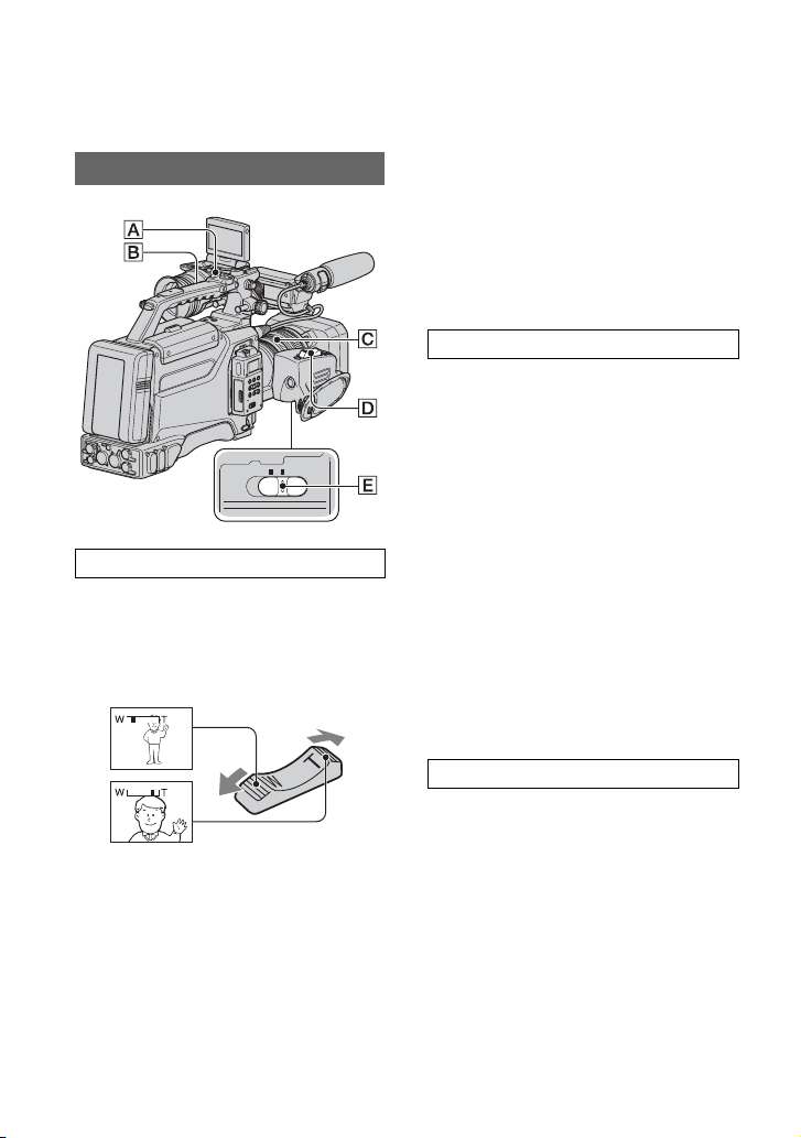
Adjusting the zoom
.
SERVOMANUAL
ZOOM
Using the zoom lever
Set the ZOOM switch E to SERVO.
Move the power zoom lever D slightly for
a slower zoom. Move it further for a faster
zoom.
Wide view: (Wide angle)
Close view: (Telephoto)
z Tips
• The minimum distance required between your
camcorder and the subject for focus is about 1
cm (about 13/32 in.) for wide angle and about
80 cm (about 2 5/8 feet) for telephoto.
• The focus may not be adjusted at certain zoom
positions if the subject is within 80 cm (about
2
5/8 feet) from your camcorder.
• When you set [FOCUS MACRO] to [OFF] or
the focus ring to the mode A position (
you cannot focus on a subject within 80 cm
(about 2 5/8 feet) regardless of the zoom
position (
• Be sure to keep your finger on the power zoom
p. 71).
lever D. If you move your finger off the power
zoom lever D, the operation sound of the
power zoom lever D may also be recorded.
p. 31),
Using the handle zoom
1 Set the ZOOM switch E to SERVO.
2 Set the handle zoom switch B to VAR
or FIX.
z Tips
• When you set the handle zoom switch B to
VAR, you can zoom in or out at variable
speed.
• When you set the handle zoom switch B to
FIX, you can zoom in or out at fixed speed
set in [HANDLE ZOOM] (
p. 71).
3 Press the handle zoom lever A to zoom
in or out.
b Notes
• You cannot use the handle zoom lever A when
the handle zoom switch B is set to OFF.
• You cannot change the zoom speed of the zoom
lever D with the handle zoom switch
B.
Using the zoom ring
You can zoom at the desired speed by
turning the zoom ring C. Fine adjustment
is also possible.
1 Set the ZOOM switch E to MANUAL.
2 Turn the zoom ring C to zoom in or
out.
z Tips
• You can remove the zoom pin.
30
 Loading...