

Sony HVR-M15N, HVR-M15P, HVR-M15E, HVR-M15U User Manual

Digital HD
Videocassette
Recorder
2-678-753-11(1)
Operating Instructions
HVR-M15U/M15N/M15E/M15P
2006 Sony Corporation
WARNING
To reduce fire or shock hazard, do not
expose the unit to rain or moisture.
This symbol is intended to alert the user to the
presence of uninsulated “dangerous voltage”
within the product’s enclosure that may be of
sufficient magnitude to constitute a risk of
electric shock to persons.
For customers in the U.S.A.
HVR-M15U only
If you have any questions about this product, you may
call: Sony’s Business Information Center (BIC) at 1-800686-SONY (7669)
or Write to: Sony Customer Information Services Center
6900-29 Daniels Parkway, PMB 330 Fort
Myers, Florida 33912
Declaration of Conformity
Trade Name: SONY
Model: HVR-M15U
Responsible Party: Sony Electronics Inc.
Address: 16530 Via Esprillo, San Diego, CA
92127 U.S.A.
Telephone Number: 858-942-2230
This device complies with Part 15 of the FCC Rules.
Operation is subject to the following two conditions:
(1) This device may not cause harmful interference, and
(2) this device must accept any interference received,
including interference that may cause undesired
operation.
This symbol is intended to alert the user to the
presence of important operating and
maintenance (servicing) instructions in the
literature accompanying the appliance.
Owner’s record
The model number and the serial number are located at the
name plate on the left of the unit. Record the serial number in
the space provided below. Refer to these numbers whenever
you call upon your Sony dealer regarding this product.
Model No. HVR- Serial No. ______________________
Model No. AC-L15A Serial No. ______________________
CAUTION
You are cautioned that any changes or modifications not
expressly approved in this manual could void your authority
to operate this equipment.
NOTE:
This equipment has been tested and found to comply with
the limits for Class B digital device, pursuant to Part 15 of the
FCC Rules.
These limits are designed to provide reasonable protection
against harmful interference in a residential installation.
This equipment generates, uses, and can radiate radio
frequency energy and, if not installed and used in
accordance with the instructions, may cause harmful
interference to radio communications.
However, there is no guarantee that interference will not
occur in a particular installation. If this equipment does cause
harmful interference to radio or television reception, which
can be determined by turning the equipment off and on, the
user is encouraged to try to correct the interference by one or
more of the following measures:
– Reorient or relocate the receiving antenna.
– Increase the separation between the equipment and
receiver.
– Connect the equipment into an outlet on a circuit different
from that to which the receiver is connected.
– Consult the dealer or an experienced radio/TV technician
for help.
2
NOTICE FOR CUSTOMERS IN THE
UNITED KINGDOM
HVR-M15E only
A moulded plug complying with BS1363 is fitted to this
equipment for your safety and convenience.
Should the fuse in the plug supplied need to be replaced, a
fuse of the same rating as the supplied one and approved by
ASTA or BSI to BS1362 (i.e., marked with
must be used.
If the plug supplied with this equipment has a detachable
fuse cover, be sure to attach the fuse cover after you change
the fuse. Never use the plug without the fuse cover. If you
should lose the fuse cover, please contact your nearest Sony
service station.
Disposal of Waste Electrical and Electronic
Equipment for business use (Applicable in the
European Union and other European countries
with separate collection systems)
This symbol on the product or on its
packaging indicates that this product shall not
be treated as household waste. Instead it
shall be handed over to the applicable takeback scheme for the recycling of electrical
and electronic equipment. By ensuring this
product is disposed of correctly, you will help
prevent potential negative consequences for
the environment and human health, which could otherwise
be caused by inappropriate waste handling of this product.
The recycling of materials will help to conserve natural
resources. For more detailed information about recycling of
this product, please contact your local Sony office or visit
Sony Europe’s web site for business customers:
http://www.sonybiz.net/environment
or mark)
For the customers in the Nederland
Voor de klanten in Nederland
Dit apparaat bevat een vast ingebouwde batterij die niet
vervanden hoeft te worden tijdens de levensduur van het
apparaat.
Raadpleeg uw leverancier indien de batterij toch vervangen
moet worden.
De batterij mag alleen vervangen worden door vakbekwaam
servicepersoneel.
Gooi de batterij niet weg maar lever deze in als klein
chemisch afval (KCA).
Lever het apparaat aan het einde van de levensduur in voor
recycling, de batterij zal dan op correcte wijze verwerkt
worden.
Caution
Television programs, films, video tapes and other materials
may be copyrighted. Unauthorized recording of such material
may be contrary to the provisions of the copyright laws. Also,
use of this recorder with cable television transmission may
require authorization from the cable television transmission
and/or program owner.
English
For the customers in Europe
HVR-M15E only
This product with the CE marking complies with both the
EMC Directive (89/336/EEC) and the Low Voltage Directive
(73/23/EEC) issued by the Commission of the European
Community.
Compliance with these directives implies conformity to the
following European standards:
• EN60065 :Product Safety (Supplied AC Adapter only)
• EN55103-1 :Electromagnetic Interference (Emission)
• EN55103-2 :Electromagnetic Susceptibility (Immunity)
This product is intended for use in the following
Electromagnetic Environment(s):
E1 (residential), E2 (commercial and light industrial), E3
(urban outdoors) and E4 (controlled EMC environment ex.
TV studio).
ATTENTION
The electromagnetic fields at the specific frequencies may
influence the picture and sound of this unit.
3

Table of Contents
Table of Contents
Chapter1
Overview
Chapter2
Playback and
Recording
Features ............................................................................. 6
Location and Function of Parts ....................................... 8
Front Panel .......................................................................... 8
Rear Panel ......................................................................... 13
Supplied Remote Commander .......................................... 16
Displaying Various Data..................................................18
Notes on Power Supply and Video Cassettes .............. 20
Preparing the Power Supply .............................................. 21
Inserting/Ejecting Cassettes .............................................. 21
Notes on Playback/Recording ........................................... 22
Installing the Unit Vertically ............................................. 23
Playback........................................................................... 24
Connections for Playback.................................................. 24
Settings for Playback ......................................................... 27
Chapter3
Dubbing/Editing
Playback Procedures ......................................................... 27
Playback Functions ........................................................... 28
Using the Unit as a Videocassette Recorder ................32
Connections for Recording................................................ 32
Settings for Recording ....................................................... 34
Recording Procedures ....................................................... 36
Recording Functions ......................................................... 36
Dubbing to another equipment ...................................... 37
Connections for Dubbing .................................................. 37
Dubbing procedures .......................................................... 40
Editing (Connecting with a Computer).......................... 41
Connecting the Unit to a Computer................................... 41
Preparations ....................................................................... 42
4 Table of Contents

Chapter4
Adjusting and
Setting
Through Menus
Chapter5
Maintenance
Operating the Menus ...................................................... 44
Menu Organization ............................................................ 45
Menu Contents .................................................................. 46
Troubleshooting .............................................................. 56
Warning indicators and messages ................................62
Notes on Use ................................................................... 64
Notes on the Videocassette Recorder ................................ 64
Cleaning of the Video Heads ............................................. 64
Notes on the Video Cassettes ............................................ 65
About Moisture Condensation .......................................... 66
Digital Hours Meter .......................................................... 66
About the Built-in Rechargeable Battery .......................... 67
Using your Videocassette Recorder abroad....................... 67
Notes on the License ......................................................... 67
Appendix
Compatibility of HDV, DVCAM, and DV Formats ........... 68
About i.LINK .................................................................... 73
Specifications .................................................................. 74
Index ................................................................................. 77
Submenu Index ............................................................... 78
Table of Contents 5

Chapter 1 Overview
Features
Chapter1
Overview
The HVR-M15U/M15N/M15E/M15P is a digital HD
videocassette recorder supporting HDV format and
DVCAM/DV format. The unit produces stable,
superior picture quality by digital processing and
separating image signals into color difference signals
and a luminance signal (component video). The unit
provides i.LINK (
OUT jacks, S VIDEO IN/OUT jacks, composite IN/
OUT jacks, and AUDIO IN/OUT jacks. These jacks
allow you to connect other equipment like non-linear
editors. The main features of the unit are described
below.
HDV/DV) jack, COMPONENT
HDV format
The unit can perform HDV (High-Definition Digital
Video) recording and playback on a DVCAM format
video cassette or a DV format video cassette.
The compression system of HDV format is the
MPEG2 system adopted in the high-definition
broadcasting and the Blu-ray Disk System.
The unit adopts the 1080 scanning lines (interlace
(HDV1080/60i and HDV1080/50i)/1440 × 1080
pixels) format of the HDV specifications. The
recording bit rate is approximately 25 Mbps. The unit
is equipped with an i.LINK digital interface and can be
digitally connected with HDV-compatible televisions
or computers.
DVCAM/DV format
DVCAM is based on the consumer DV format, which
uses the 4:1:1 component digital format (60i) or the
4:2:0 format (50i), and provides a
recording format for professional use. The unit
provides both DVCAM format recording/playback and
DV format in SP mode recording/playback.
For details, see “Compatibility of HDV, DVCAM, and DV
Formats” on page 68.
1
/4-inch digital
Compatible with both 1080/60i (NTSC) and
1080/50i (PAL) systems
The unit is compatible with 60i and 50i systems. You
can switch these input signals using the menu setting
(page 55). This compatibility allows you to record
(download) or play back (upload) both 50i and 60i
signals with your VCR, computer, or other equipment.
However, the unit cannot convert the color system of
the signals.
The unit set in 60i system has a field frequency of
59.94 Hz.
6 Chapter 1 Overview
High definition down convert function
Easy maintenance functions
When you want to playback a tape recorded in HDV
format, you can down convert any images to output
them. This function allows you to preview recordedimages on a monitor which is not compatible with
High-Definition (HD) format. Also, you can select an
aspect ratio from SQUEEZE, LETTER BOX (except
HDV/DV jack output), or EDGE CROP.
Multiple input/output interfaces
HDV/DV jack, COMPONENT OUT jacks, S
VIDEO jacks and VIDEO jacks and AUDIO jacks are
equipped on the unit and enable the connection with
various devices.
JOG AUDIO function
If you use the optional remote control unit DSRM-10
(not supplied), audio can be monitored at various
playback speeds when in jog/shuttle mode.
(Jog audio cannot be output when the tape is recorded
in HDV format.)
• Self-diagnostics/alarm functions: The system
automatically detects an invalid operation, bad
connection or a malfunction, and outputs a
description, a cause and a recovery method with
COMPONENT OUT jacks, S VIDEO jack, and
VIDEO jack.
• Digital hours meter: A digital hours meter counts
four types of time data—operating time, drum
rotation time, tape running time, and tape threading/
unthreading. The digital hours data are indicated on
the menu.
..............................................................................................
, , and are trademarks of Sony
Corporation.
is a trademark of Sony Corporation and
Victor Company of Japan Ltd.
All other product names mentioned here may be the
trademarks or registered trademarks of their respective
companies. “™” and “®” are not mentioned in each
case in this manual.
Chapter 1 Overview
Screen Language Setting
You can select the language.
The default language setting is English.
See page 53 to change the screen language.
Compact size allowing vertical installation
The compact size of the unit allows installation in a
vertical position and saves space. During non-linear
editing, you can install the unit in a vertical position
next to the computer and save working space.
Chapter 1 Overview 7

Location and Function of Parts
Front Panel
Chapter 1 Overview
2 Indicator section
1 Remote sensor
2 DISPLAY OUTPUT
switch
3 ON/STANDBY switch
and lamp
4 INPUT SELECT switch
(see page 11)
1 Remote sensor
2 DISPLAY OUTPUT switch
Selects the destination for the text data to be
superimposed via output jacks.
OFF : Does not superimpose text data to output.
S VIDEO/VIDEO : Superimposes text data to S
VIDEO OUT jack and VIDEO OUT jack.
ALL : Superimposes text data to COMPONENT
OUT jacks, S VIDEO OUT jack, and VIDEO
OUT jack.
3 ON/STANDBY switch and lamp
Press this switch to turn the unit on, and the ON/
STANDBY lamp lights up in green. When you press
this switch again, the unit goes into STANDBY mode
and the lamp lights up in red.
4 INPUT SELECT switch
Switches the signal input jack from
HDV/DV jack,
S VIDEO jack, and VIDEO jack.
HDV/DV : Inputs a signal from
HDV/DV jack.
S VIDEO : Inputs a signal from S VIDEO jack.
VIDEO : Inputs a signal from VIDEO jack.
5 Cassette Lid
6 J/j/K/k button
7 EXEC (execute)
button
8 MENU button
1 Tape transport control
section
(see page 10)
Notes
•Do not change the setting of this switch while
recording in progress, or it causes noise added to
images and sounds. Also, a part of the tape where the
change of setting applied will not be recorded
properly. Also, the time code may operate
discontinuously.
• If you change the setting of this switch while
recording in progress, the output signal from
HDV/
DV jack may be interrupted. Also, the unit may detect
signals such as a copyright information signal
incorrectly.
•When a signal is input from
HDV/DV jack, the
settings of the menu listed below are unavailable.
– 60i/50i SEL
– AUDIO MODE
– AUDIO LOCK
– AUDIO AGC
– AUDIO REC LV
5 Cassette Lid
Open this lid to insert or eject a cassette.
For details of usable cassettes, see “Notes on Power Supply
and Video Cassettes” on page 20.
For details of inserting or ejecting a cassette, see “Inserting/
Ejecting Cassettes” on page 21.
8 Chapter 1 Overview

6 J/j/K/k button
Use these buttons in menu settings and other settings.
7 EXEC (execute) button
Use this button in menu settings.
8 MENU button
Press this button to display the menu on screen.
Chapter 1 Overview
Chapter 1 Overview 9

Location and Function of Parts
1 Tape transport control section
Chapter 1 Overview
7 STOP button
1 Tape transport indicators
2 REC (record) button
3 PAUSE button
4 FF (fast forward) button
5 PLAY button
6 REW (rewind) button
1 Tape transport indicators
2 REC (record) button
When you press and hold this button then press PLAY
button, the each indicator lights and recording starts. If
you press this button while the tape is stopped, you can
check EE picture and audio signals for a moment.
When HDV/DV is selected, if [HDV/DV IN TC] in
[TC/UB SET] menu is set to [EXTERNAL], you can
also check EE time code signals. Press STOP button to
end the check.
For details, see “EE/PB SEL” in “IN/OUT REC” menu on
page 48.
For details of the time code, see “TC/UB SET” on page 52.
Notes
• The unit does not have an LP recording mode of the
consumer DV format. Only recording in SP mode is
available.
• To set the unit to recording pause mode with the
remote control unit DSRM-10 (not supplied), press
PAUSE button while holding down PLAY button to
set the unit to the playback pause mode, then press
REC button on the DSRM-10.
• When the recording mode is displayed in HDV, it
may take a few seconds to start recording. During this
time, REC indicator blinks.
3 PAUSE button
Press this button to set the unit to pause mode while
recording or playing. Press this button again to resume
the operation.
4 FF (fast forward) button
When you press this button, the indicator lights and the
tape is fast forwarded. During fast forward, the picture
does not appear on the monitor (you can see the picture
as it is seen in EE mode
1)
during fast forward). To
locate a scene while monitoring the picture, keep
pressing this button during fast forward, playback or in
playback pause mode (picture search).
Notes
• If you set [EE/PB SEL] in [IN/OUT REC] menu to
[PB], EE picture and EE audio signals are not output.
• If you set [FF/REW SPEED] in [VTR SET] menu to
[SHUTTLEMAX], the picture is played back during
fast forward.
For details on running speed with [SHUTTLEMAX], see
“FF/REW SPEED” in “VTR SET” menu on page 51.
........................................................................................................................................................................................................
1) “EE” stands for “Electric to Electric.” In EE mode, the video and audio signals input to the VCR’s recording circuitry do
not pass through any magnetic conversion circuits but output via electric circuits only. This mode is used to check the input
signals and adjust input levels. The pictures output in EE mode are referred to as EE pictures.
10 Chapter 1 Overview
5 PLAY button
When you press this button, the indicator lights and
playback begins.
If you press this button while holding down REW
button during stop, the tape is rewound to its beginning
and starts playing automatically (during rewind, REW
indicator lights and PLAY indicator blinks).
Notes
• When the unit is playing back a part of the tape
where the recording format has been changed within
HDV format, DVCAM format, or DV format, or
between 60i format and 50i format, the picture and
sound may be distorted.
• The unit does not have an LP recording mode of the
consumer DV format.
6 REW (rewind) button
When you press this button, the indicator lights and the
tape starts rewinding.
During rewind, the image on the monitor is not
displayed (you can see the picture as it is seen in EE
mode
during rewind). To locate a scene while
monitoring the picture, hold this button down during
rewind, playback or in the playback pause mode.
If you press PLAY button while holding down this
button during stop, the tape is rewound to its beginning
and starts playing automatically (during rewind, REW
indicator lights and PLAY indicator blinks).
Notes
• If you set [EE/PB SEL] in [IN/OUT REC] menu to
[PB], EE picture and EE audio signals will not be
output.
• If you set [FF/REW SPEED] in [VTR SET] menu to
[SHUTTLEMAX], the picture is played back during
rewind.
For details on running speed with [SHUTTLEMAX], see
“FF/REW SPEED” in “VTR SET” menu on page 51.
7 STOP button
Press this button to stop the tape transport operation
completely.
Chapter 1 Overview
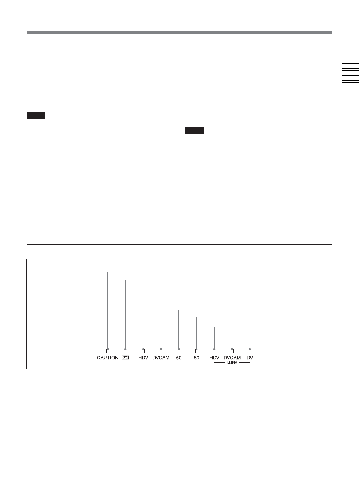
2 Indicator section
1 CAUTION indicator
2 q (cassette) indicator
3 HDV indicator
1 CAUTION indicator
Blinks when an error occurs.
For details on cautions, see “Self-diagnosis display/
Warning Indicators” on page 62.
4 DVCAM indicator
5 60 indicator
6 50 indicator
7 HDV-i.LINK indicator
8 DVCAM-i.LINK indicator
9 DV-i.LINK indicator
2 q (cassette) indicator
Lights when a digital video cassette is loaded.
This indicator lights during standby, when the cassette
is inserted to the unit. While the cassette is being
ejected, the indicator blinks.
For details of inserting or ejecting a cassette, see
“Inserting/Ejecting Cassettes” on page 21.
(Continued)
Chapter 1 Overview 11

Location and Function of Parts
3 HDV indicator
Lights when the unit is in the following operating
status.
• When a tape recorded in HDV format is being played
Chapter 1 Overview
back.
• When HDV signals are input through the i.LINK
interface.
• When [HDV/DV SEL] in [IN/OUT REC] menu is set
to [HDV].*
* Even when [HDV/DV SEL] is set to [AUTO] with no
signal input, while the last signal input was HDV format
or the last tape played was in HDV format, this indicator
lights.
4 DVCAM indicator
Lights when the unit is in the following operating
status.
• When a tape recorded in DVCAM format is being
played back.
• When [HDV/DV SEL] in [IN/OUT REC] menu is set
to [DV] and [
REC MODE] in [IN/OUT REC]
menu is set to [DVCAM] (during recording or in EE
mode).*
* Neither HDV indicator nor DVCAM indicator lights
during recording in DV (SP) format or a playback of a
tape recorded in DV (SP) format.
8 DVCAM-i.LINK indicator
Lights when DVCAM signals are input/output through
the i.LINK interface.
9 DV-i.LINK indicator
Lights when DV signals are input/output through the
i.LINK interface.
5 60 indicator
Lights when the unit is in the following operating
status.
• During recording or in EE mode when [60i/50i SEL]
in [OTHERS] menu is set to [60i].
• During HDV1080/60i or NTSC signals are input
from
HDV/DV jack.
• A tape that has HDV1080/60i or NTSC signals are
being played back.
6 50 indicator
Lights when the unit is in the following operating
status.
• During recording or in EE mode when [60i/50i SEL]
in [OTHERS] menu is set to [50i].
• During HDV1080/50i, or PAL signals are input from
HDV/DV jack.
• A tape that has HDV1080/50i or PAL signals are
being played back.
7 HDV-i.LINK indicator
Lights when HDV signals are input/output through the
i.LINK interface.
12 Chapter 1 Overview
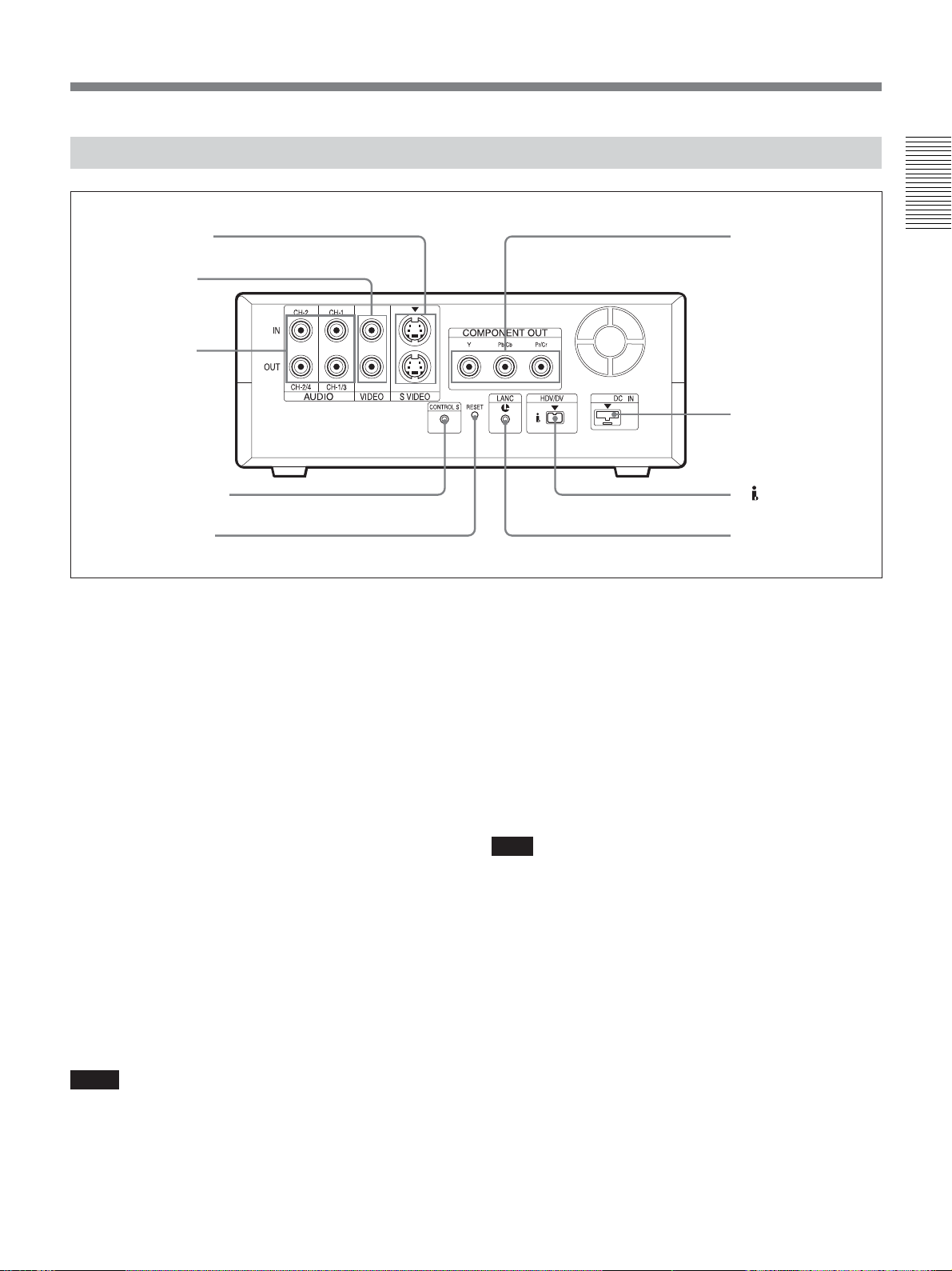
Rear Panel
1 S VIDEO jacks
2 VIDEO jacks
3 AUDIO jacks
4 CONTROL S jack
5 RESET button
1 S VIDEO jacks
To connect a device equipped with an S VIDEO jack,
use S VIDEO jacks on the unit.
If you use S VIDEO jacks, you can input/output highquality video with less signals deterioration in quality
than the one connected to the standard VIDEO jack.
When DISPLAY OUTPUT switch is set to
S VIDEO/VIDEO or ALL, text data such as the time
code, menus, and alarm messages are superimposed on
an external monitor connected to S VIDEO jack (page
18).
6 COMPONENT
OUT jacks
7 DC IN jack
8 HDV/DV jack
9 LANC jack
• If you input a sound whose level exceeds the
acceptable range, the sound recorded will be
distorted.
For details on the available volume levels, see the
“Specifications” of the unit (page 74).
4 CONTROL S jack
Connect to a remote control unit DSRM-10 (not
supplied) for controlling the unit.
You can also use the DSRM-20 (no longer
manufactured: not supplied).
Chapter 1 Overview
2 VIDEO jacks
Use to input and output analog video signals.
Text data is superimposed on a monitor in the same way
as S VIDEO jack connection (page 18).
3 AUDIO jacks
Use to input and output analog audio signals.
When [AUDIO MODE] in [AUDIO SET] menu is set
to [FS32K], audio source will be recorded on channels
1 and 2.
Notes
•When [AUDIO MIX] in [AUDIO SET] menu is set
to [MIX], the audio output level becomes 50%
(–6 dB) of the original audio level on each channel.
Note
When you use a CONTROL S device, set
[COMMANDER] in [OTHERS] menu to
[CONTROL S].
5 RESET button
If you press this button with the tip of a ballpoint pen
or similar tool, the following settings are initialized.
–[CLOCK SET] (page 54) and [60i/50i SEL]
(page 55) in [OTHERS] menu.
– The setting on the unit except the menu settings.
(Continued)
Chapter 1 Overview 13

Location and Function of Parts
6 COMPONENT OUT jacks
Use to output component signals.
To connect a device equipped with the component
video input connectors, use COMPONENT OUT jacks
on the unit. If you use COMPONENT OUT jacks, you
Chapter 1 Overview
can output high-quality video with even less signal
deterioration in quality compared with S VIDEO jack.
You can set the output video format by using
[COMPONENT] of [VIDEO OUT] in [IN/OUT REC]
menu.
When DISPLAY OUTPUT switch is set to ALL, text
data such as time code, menu, and alarm messages are
superimposed on a monitor connected using
COMPONENT OUT jacks (page 18).
Notes
• When you change the video format setting of
[COMPONENT] of [VIDEO OUT] in
[IN/OUT REC] menu, the images output from
HDV/DV jack, S VIDEO jack, and VIDEO jack may
be distorted for a moment.
• The output level of COMPONENT OUT jacks is as
follows:
Output at 480i NTSC
With [BETACAM] selected in [IN/OUT REC] menu
Y: 1.0 Vp-p
(with 0.286 Vp-p sync negative,
output impedance 75 Ω (ohms), unbalanced)
Pb/Cb/B-Y, Pr/Cr/R-Y: 0.7 Vp-p
(output impedance 75 Ω (ohms), unbalanced)
(75% color bars with 7.5 IRE setup)
With [SMPTE] selected in [IN/OUT REC] menu
Y: 1.0 Vp-p
(with 0.3 Vp-p sync negative,
output impedance 75 Ω (ohms), unbalanced)
Pb/Cb/B-Y, Pr/Cr/R-Y: 0.7 Vp-p
(output impedance 75 Ω (ohms), unbalanced)
(100% color bars with no setup)
Output with other settings
Y: 1.0 Vp-p
(output impedance 75 Ω (ohms), unbalanced)
Pb/Cb/B-Y, Pr/Cr/R-Y: 0.7 Vp-p
(output impedance 75 Ω (ohms), unbalanced)
(100% color bars with no setup)
480i/480p:
Y: with 0.3 Vp-p sync negative
1080i:
Y/Pb/Pr: with 0.6 Vp-p 3-level sync
• When you play back HDV-formatted tape with
copyright protected signals or input i.LINK signals
with copyright protection to
HDV/DV jack, pictures
may be output in either 480i (NTSC) or 576i (PAL)
format regardless of the setting of [COMPONENT]
of [VIDEO OUT] in [IN/OUT REC] menu.
•When you play back a tape in DVCAM/DV, and
while an EE picture in NTSC/PAL is displayed, the
480i resolution or the 576i resolution is output,
regardless of the setting of [COMPONENT] of
[VIDEO OUT] in [IN/OUT REC] menu.
7 DC IN jack
Connect to the AC outlet using the supplied AC
adaptor.
8
HDV/DV jack (4-pin)
Use this jack to input/output the digital signals that
complies with the i.LINK standard. Use when a device
connected to the unit has an i.LINK jack. If you
connect the unit and another device using
HDV/DV
jack, you can minimize deterioration of picture quality
during recording, dubbing, or capturing still pictures,
all by means of digital signal processing.
For details, refer to the instruction manual of the external
device.
Notes
•When you connect with the i.LINK cable to a
computer and the unit, check the direction of the jack.
If you forcibly insert the jack, the terminal may be
damaged or cause the unit to malfunction. Allign v
mark of the i.LINK cable with V mark on the unit
and insert the i.LINK cable.
• This jack is only compatible with HDV1080i/
DVCAM/DV signals.
For details, see “About i.LINK” on page 73.
• If video signals have been input to HDV/DV jack
and you output these video signals to S VIDEO or
VIDEO connectors, the sync and burst of the
corresponding EE picture is not synchronized.
• If the unit is connected to a device equipped with a
6-pin i.LINK jack, when you intend to disconnect or
reconnect the i.LINK cable, turn off the device and
pull out the plug of its power cord from the AC outlet
beforehand. If you connect or disconnect i.LINK
cable while the device is connected to the AC outlet,
high-voltage current (8 to 40 V) is output from the
i.LINK jack of the device to the unit, which may
cause a malfunction.
14 Chapter 1 Overview

• When connecting a device that has a 6-pin i.LINK
jack to the unit, first, connect the plug of the cable to
the 6-pin i.LINK jack.
• The video signal which is input from
HDV/DV jack
will output directly to COMPONENT OUT jacks, S
VIDEO jack, and VIDEO jack with the jitter of
i.LINK signal. This jitter may be displayed on a
monitor continuously. Be careful with this jitter when
you connect the unit to other recording devices for
recordings. This jitter will not affect on a recording
with the unit.
• When you change the video format setting of
[DOWN CONVERT] of [i.LINK SET] in [IN/OUT
REC] menu, the video signal output from
COMPONENT OUT jacks, S VIDEO OUT jack, or
VIDEO OUT jack might be distorted for a moment.
9 LANC jack
Use this jack when controlling the tape transport
operation of the unit using a device that has a LANC
jack.
Notes
• LANC jack on the unit has only LANC-S functions.
The unit has no LANC-M functions. A device that is
set to LANC-S mode cannot be connected to the unit.
Either this, the unit or the other device may not
operate properly.
•When using the unit as a player, set LANC mode on
the recorder to M. A device that does not have an M/
S switching function cannot be used to control the
unit.
• When the device for connecting to the unit has
[LANC-M] function to switch between SHUTTLE A/
B, select SHUTTLE A for HDV-formatted tape, and
SHUTTLE B for the DVCAM/DV-formatted tape.
• LANC connection transmits command signals for
playback, stop, pause playback, as well as the time
code, tape counter, and data status of the unit.
• Jacks labeled CONTROL L have the same function
as LANC jacks.
• There are some limitations when you edit an HDVformatted tape.
Refer to the “Notes” in “Preparations” on page 42.
Notes on all Video output jacks
• The unit is only compatible with standard video
signals. If you input the types of video signals shown
below, recorded picture and sound may be distorted.
– Signals from some home game machines
Chapter 1 Overview
– Blue background screen or gray background screen
from a consumer VCR
– Pictures played at a speed other than normal by a
VCR that does not have the TBC (Time Base
Corrector)
– Video signals in which the sync signals are
distorted
– Signals from a defective cassette (tape or recording
condition is bad) played by an analog VCR that
does not have TBC
• To absorb the jitter of input video signals, the
distortion of video signals are processed in the
underscan portion. You may see this procedure on an
1)
underscan monitor, yet this is not a malfunction.
Also, the picture recorded on the tape will not be
affected.
• To output video signals to VIDEO, S VIDEO, or
COMPONENT OUT jacks without text data, set
DISPLAY OUTPUT switch to OFF.
• During recording or in EE mode, the subcarrier of
the color signal to be output from the unit is not
synchronized with the horizontal sync signal. The
color of the picture or the horizontal sync signal may
be distorted depending on the type of monitor
connected to the unit.
........................................................................................................................................................................................................
1) LANC (Local Application Control bus system):
Bidirectional interface used to control a consumer VCR
Chapter 1 Overview 15
Location and Function of Parts
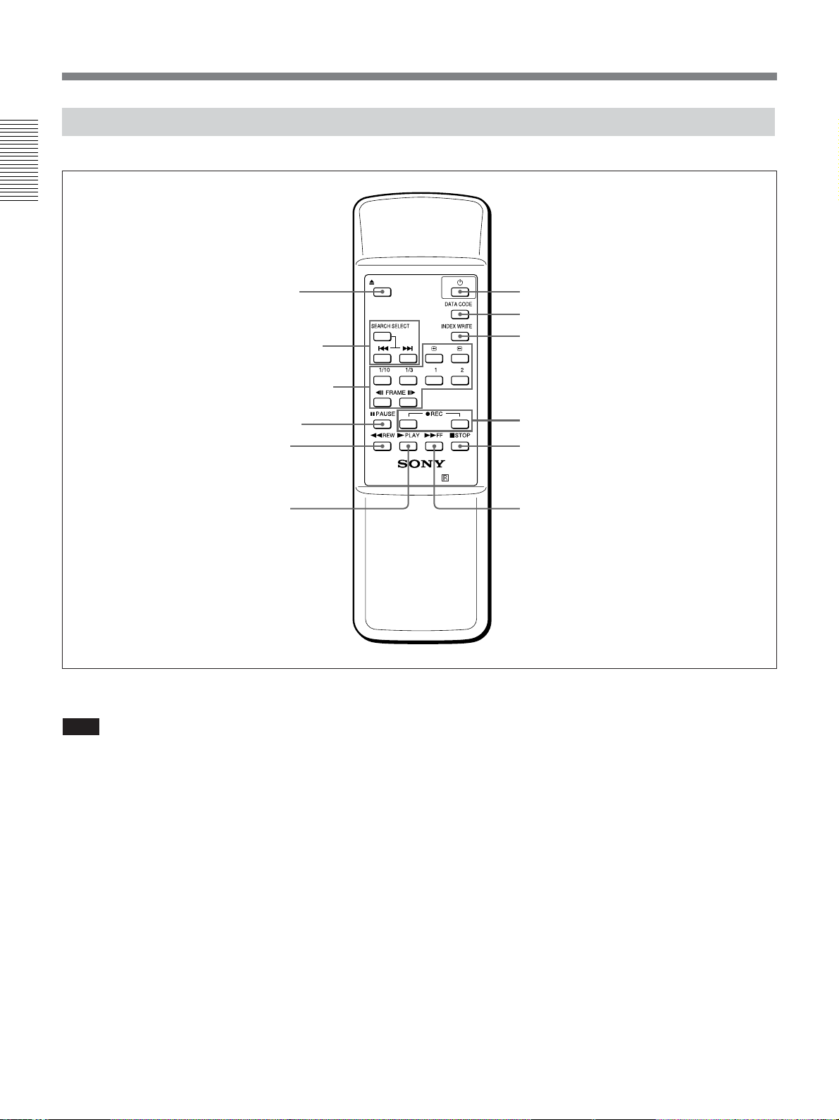
Supplied Remote Commander
Chapter 1 Overview
1 EJECT button
2 SEARCH SELECT
buttons
3 Buttons for playing at
various speeds
4 PAUSE button
5 REW button
6 PLAY button
EJECT
××××
VTR RMT-DS5
qs 1 switch
qa DATA CODE button
0 INDEX WRITE button
9 REC buttons
8 STOP button
7 FF button
1 EJECT button
Note
The unit does not open and close Cassette Lid 5
(page 8) automatically. When you eject a tape by
using EJECT button on Remote Commander, open
Cassette Lid beforehand, then press EJECT button.
2 SEARCH SELECT buttons
Press these buttons to search for scenes using the
search function.
For details on the search function, see “Searching using the
search function” on page 30.
3 Buttons for playing at various speeds
You can play back a tape at normal speed or at a speed
other than normal with these buttons.
For details, see “Playing at various speeds” on page 29.
4 PAUSE button
16 Chapter 1 Overview
5 REW (rewind) button
6 PLAY button
7 FF (fast forward) button
8 STOP button
9 REC (record) buttons
When you press both these buttons at the same time,
REC indicator and PLAY indicator on the front panel
light and recording begins.
0 INDEX WRITE button
Press this button during recording to mark an index.
For details on an index, see “Marking an index” on page 36.
qa DATA CODE button
Press this button to display the data codes (recording
date/time, camera data).
For details on data codes, see “Displaying information
(data codes) recorded on a tape” on page 28.
qs 1 (on/standby) switch
Notes
• The command mode of the supplied Remote
commander is set to VTR4.
• Set [COMMANDER] in [OTHERS] menu to
[WIRELESS] to enable Remote Commander to
control the unit.
• In addition to Remote Commander supplied with the
unit, the unit accepts signals from any Sony Remote
Commander whose command mode is set to VTR4.
To disable the control from Remote Commander, set
[COMMANDER] in [OTHERS] menu to
[CONTROL S].
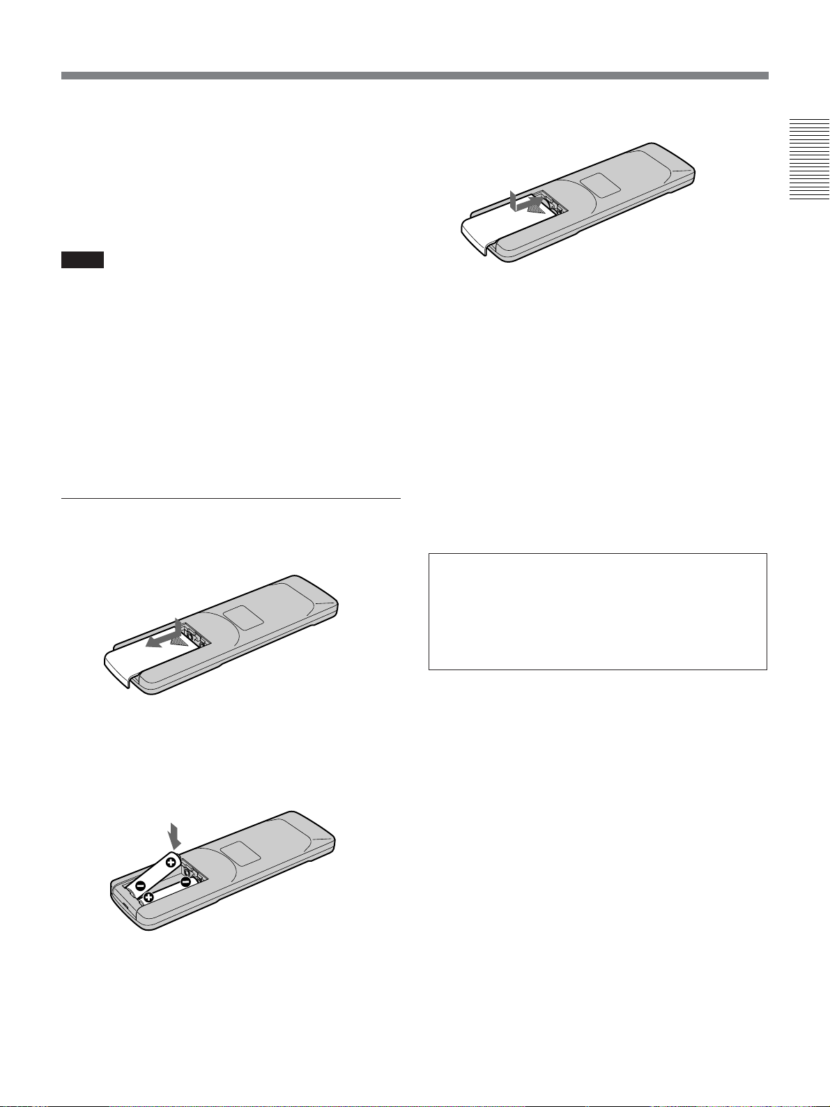
3 Put the lid back.
Chapter 1 Overview
Notes on batteries
• Make sure that the battery orientation is correct when
inserting batteries.
• Do not mix an old battery with a new one, or mix
different types of batteries.
• If you do not intend to use Remote Commander for a
long time, remove the batteries to avoid damage from
battery leakage. If the batteries have leaked, remove
them, wipe the battery compartment dry and replace
the batteries with new ones.
Battery installation
1 Push and slide the lid to open.
2 Install two size AA (R6) batteries (supplied) with
the correct polarity.
Be sure to install the
battery from the # side.
To remove the batteries
Remove the lid as step 1 and take out the batteries.
WARNING
Battery may explode or leak if mistreated. Do not
recharge, disassemble or dispose of in fire.
Check the valid date (month-year) displayed on
the batteries.
Chapter 1 Overview 17
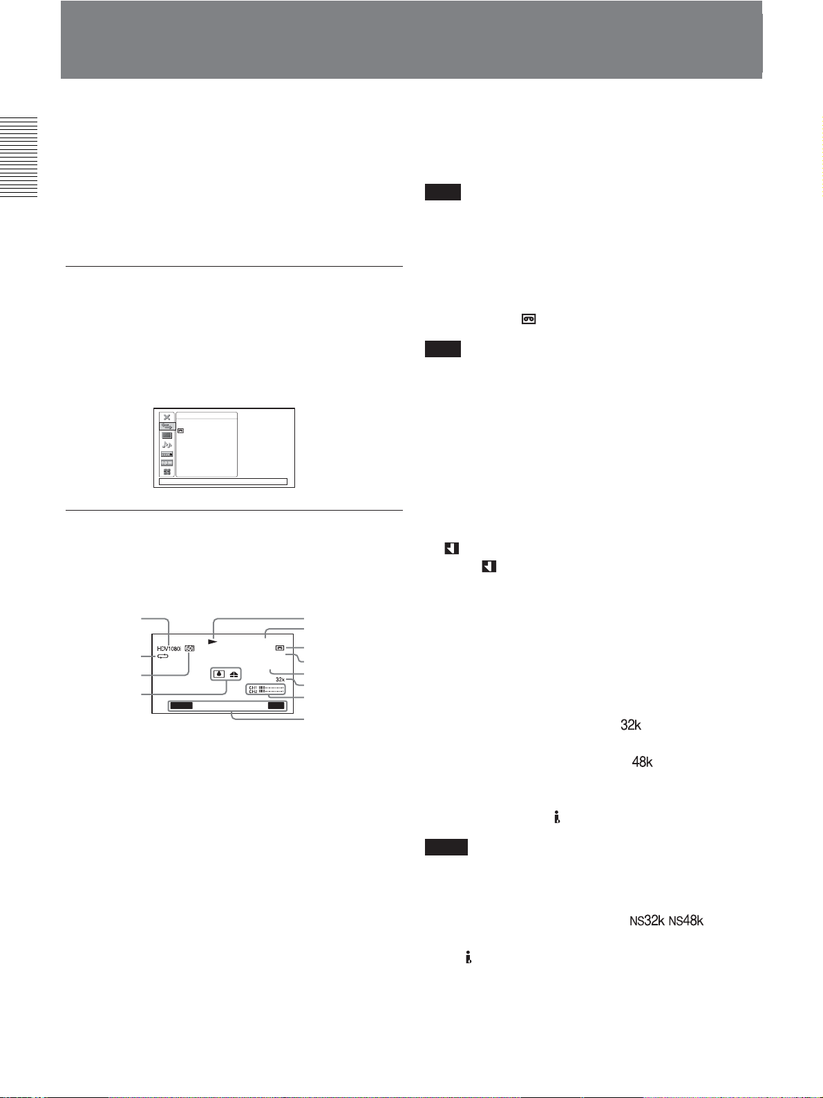
Displaying Various Data
The unit can display various superimposed text data on
an external monitor connected to the unit.
In this operation manual, the menu screen etc. is
Chapter 1 Overview
displayed in English. You can change the desired
language with the screen language setting.
For details, see page 53.
Menu screen
Press MENU button to display the menu screen. You
can change or check the menu item settings on this
screen.
For details on the menu, see “Chapter 4 Adjusting and
Setting Through Menus” on page 44.
Data display screen
IN/OUT REC
HDV/DV SEL
REC MODE
VIDEO OUTPUT
i.LINK. SET
480i LEVEL
EE/PB SEL
[
MENU] : END
6 Time code indicator
In the drop frame mode, a period is displayed between
the minutes and seconds (i.e., 00:12.58:00).
Note
When you play back a tape without having the time
code set or the time code unrecognized on the unit
cannot be displayed correctly.
7 Remaining tape time indicator
Displays the remaining tape time.
For details, see “ REMAINING” on page 49.
Note
When you insert a cassette in which the tape has been
rewound to the beginning, this indicator will not show
the remaining tape time. The remaining tape time is
displayed after the tape runs for a while.
8 INPUT SELECT indicator
Changes according to the position of INPUT SELECT
switch ([HDV/DV IN], [S VIDEO IN], or [VIDEO
IN]).
You can check important information for normal
recording or playback, such as time code or remaining
tape time, on the screen.
1
2
3
4
AUTO
F1.4 ATW
00:12:34:12
dB
60min
HDV/DV
INDEX 00
SEARCH
18018
5
6
7
IN
8
9,0
qa
qs
qd
1 Format indicator
[HDV1080i], [DVCAM], or [DV SP] are displayed.
2 Repeat indicator
Displays the repeat indicator when [AUTO REPEAT]
in [VTR SET] menu is set to [ON].
3 60i/50i indicator
4 Alarm indicator
Displays an alarm indicator.
For details on alarm indicators, see “Warning indicators
and messages” on page 62.
9
(Index) indicator
Displays
when an index has been marked.
0 Search indicator
Displays the search mode when you search for scenes
using Remote Commander.
For details on the search function, see “Searching using the
search function” on page 30.
qa Audio mode indicator
In the recording mode, displays
when you select
[FS32K] for [AUDIO MODE] in [AUDIO SET]
menu. When you select [FS48K],
is displayed.
During playback, displays the audio mode recorded on
the tape. During i.LINK input, displays the audio mode
of the signal input to
Notes
HDV/DV jack.
• The audio mode will not be displayed when [HDV/
DV SEL] in [IN/OUT REC] menu is set to [HDV].
• Signals other than HDV/DVCAM lock mode will
become non-standard audio and
/ is
displayed during playback or when the signal is input
from
HDV/DV jack.
5 Tape transport mode indicator
Displays the tape transport mode.
18 Chapter 1 Overview

qs Audio level meters
For details of the audio level meter display, see “AUDIO
MIX” in “AUDIO SET” menu on page 50.
qd Date/time and camera data indicator
When you press DATA CODE button of Remote
Commander or when you select [DATE] or
[CAMERA DATA] of [DATA CODE] in [DISPLAY
SET] menu, you can switch the display between
recordings date/time and camera data.
For details on the date/time and camera data indicator, see
“Displaying information (data codes) recorded on a tape”
on page 28.
Chapter 1 Overview
Chapter 1 Overview 19
Chapter 2 Playback and Recording
Notes on Power Supply and Video Cassettes
Chapter2
Playback and
Recording
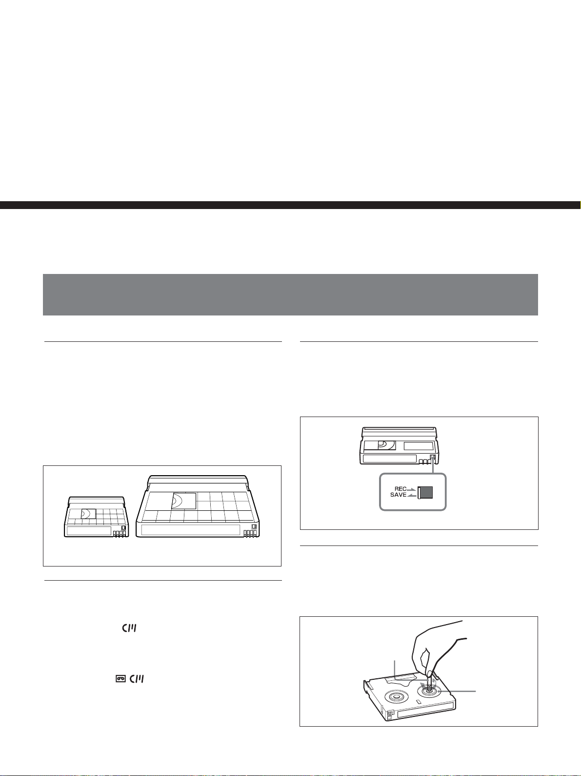
Usable cassettes
We recommend you to use a DigitalMasterTM cassette
of standard HDV/DVCAM/DV cassette (such as
PHDV-276DM), or mini HDV/DVCAM/DV cassette
(PHDVM- 63DM) for recording in HDV/DV format.
We recommend you to use a standard DVCAM
cassette, Mini-DVCAM cassette, or DigitalMaster
described above for recording in DVCAM format.
Mini cassette
Standard cassette
TM
Cassette memory
Some Mini cassettes and standard cassettes have the
cassette memory (
not support cassette memory.
However, if you use the DSR-25/45/50 as a recorder,
the unit accesses cassette memory only if the recorder
is set to [AUTO
mark). The unit, however, does
].
To save a recording
To prevent accidental erasure of a recording, set REC/
SAVE switch on the cassette to SAVE. To record or
dub audio on a tape, set the switch to REC.
Set to SAVE.
REC/SAVE switch
Checking the tape for slack
Using a paper clip or a similar object, turn the reel
gently in the direction shown by the arrow. If the reel
does not move, there is no slack.
Paper clip, etc.
Reel
20 Chapter 2 Playback and Recording
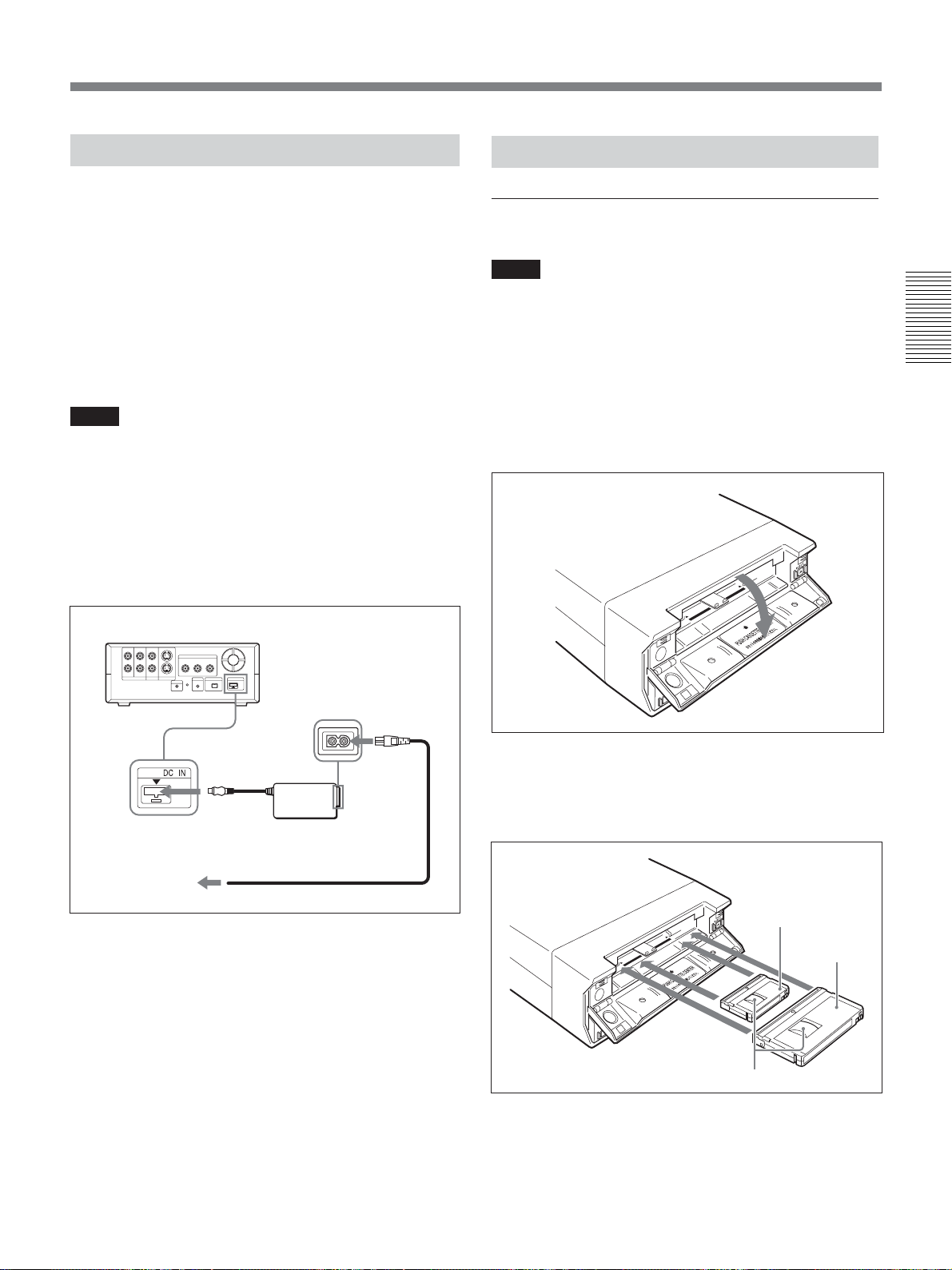
Preparing the Power Supply
Connect the power cord (supplied) to the AC adaptor
(supplied) and the DC plug of the AC adaptor to DC
IN jack on the unit. Next, connect the power plug to an
AC outlet. When you disconnect the power cord, be
sure to unplug the power cord from the AC outlet first.
PRECAUTION
Even if this unit is turned off, AC power (house
current) is still supplied to it while connected to the
wall outlet via the AC adapter.
Notes
•Never short-circuit the DC plug of the AC adaptor
with a metal object. A short circuit can damage the
unit.
•Use a nearby wall outlet when using the AC adaptor.
Disconnect the AC adaptor from the wall outlet
immediately if any malfunction occurs.
•Do not use the AC adaptor placed in a narrow space,
such as between a wall and furniture.
Inserting/Ejecting Cassettes
To insert a cassette
Notes
•Do not insert the cassette forcibly. The unit may be
damaged.
•Do not eject/load the cassette in a place subject to
light. Close Cassette Lid when the unit is in use. The
internal sensor of the unit may operate incorrectly if
too much light falls on the unit.
1 With the unit powered on, confirm that q
indicator is off, then open Cassette Lid.
Chapter 2 Playback and Recording
HVR-M15 (rear panel)
To DC IN
jack
Power cord (supplied)
To a wall outlet
AC adaptor
(supplied)
[CLOCK SET] screen appears when you turn on the
unit for the first time.
Refer to page 54 on how to set the date and time.
2 After checking the tape for slack, hold the cassette
so that the tape window is facing upward, then
insert it into the unit.
The tape is inserted into the unit automatically.
Mini cassette
(Insert the mini cassette
into the center of the
cassette compartment.)
Standard
cassette
Tape window facing upward
(Continued)
Chapter 2 Playback and Recording 21
Notes on Power Supply and Video Cassettes
Notes
•When inserting a cassette, hold the back edge of the
cassette in the center and push it until the cassette is
inserted deep into the unit. If you hold the ends, the
cassette may not be loaded properly.
• If the cassette does not load or is loaded only
halfway, eject it once, and then insert it again. In such
a case, if you insert the cassette forcibly, the cassette
may not be loaded properly or malfunctions may
occur.
• It takes a few seconds for the unit to recognize the
Chapter 2 Playback and Recording
cassette and find the proper location on the tape being
loaded.
3 Close Cassette Lid.
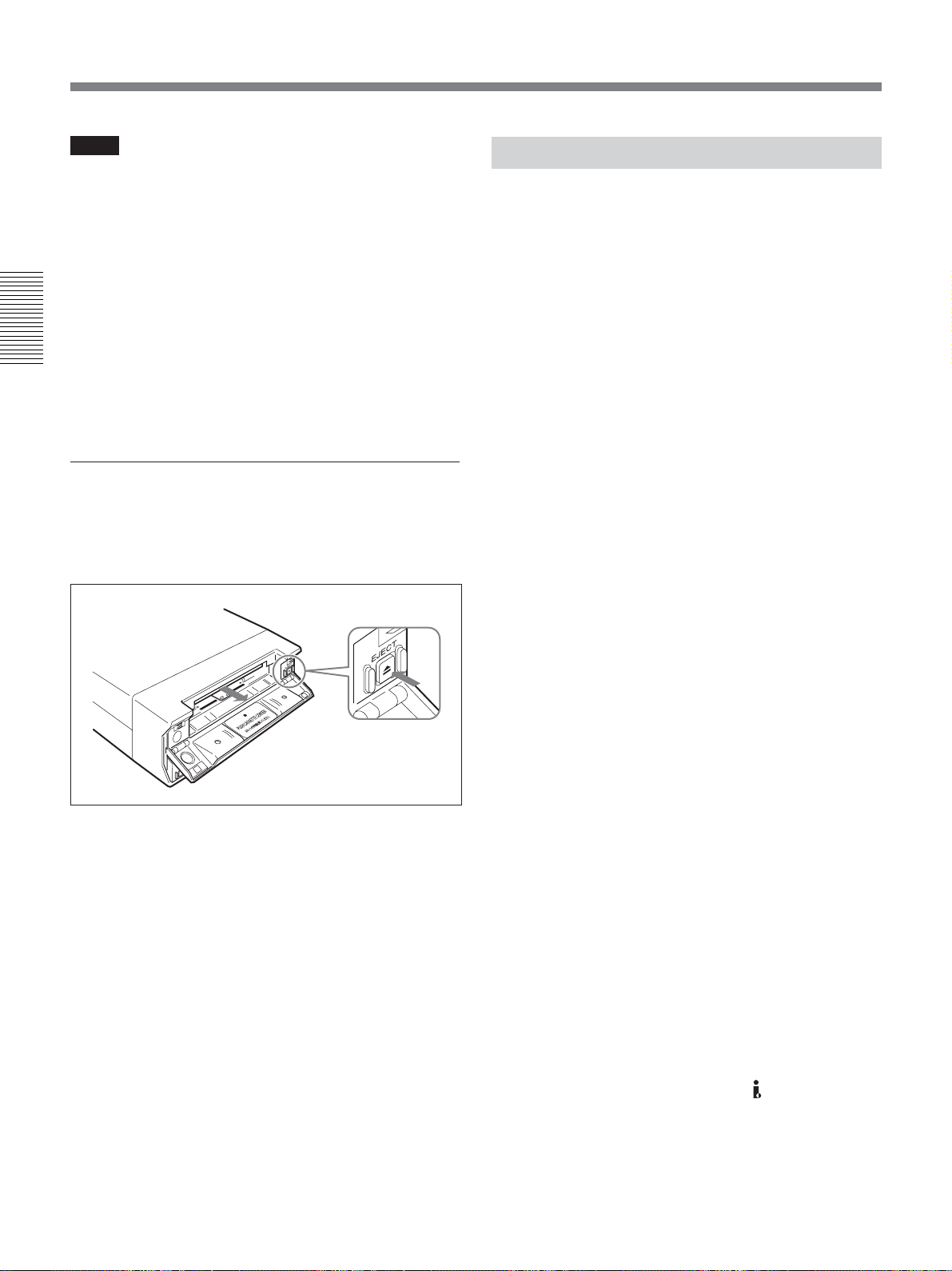
To eject the cassette
1 With the unit powered on, open Cassette Lid. Press
EJECT button located at the right side of the
cassette compartment.
Notes on Playback/Recording
No compensation for contents of the
recording
Contents of the recording cannot be compensated for if
recording or playback is not successful due to a
malfunction of the unit, video tape, etc.
Copyright precautions
Television programs, films, video tapes, and other
materials may be copyrighted. Unauthorized recording
of such materials may be contrary to the copyright
laws.
On recording
You cannot record or output EE signals to any
software having copyright protection signals on the
unit. If you start recording protected video and audio
signals, a warning appears on the monitor screen and
the unit stops recording.
During recording, do not change INPUT SELECT
switch setting. If you do so, the unit may mistakenly
recognize that a copyright control signal has been
input.
The cassette is unloaded and ejected.
2 Remove the cassette from the unit. Close Cassette
Lid.
On playback
When you play back software having copyright
protected signals on the unit, you may not copy or
output to other equipment.
Limitations caused by differences in format
The unit can record and play back tapes recorded in
HDV (1080/60i, 1080/50i), DVCAM, or DV format.
However, due to differences in format, you may not
play back or edit some tapes affected by recording
conditions of the tape (i.e., a tape originally recorded
in DV format is dubbed in DVCAM format).
The unit cannot input/output, record, or play back a
tape other than 1080/60i or 1080/50i format such as
1080/30F, 1080/25F, 1080/24F, 720/25p, 720/24p
format.
The unit cannot input/output, record, or play back a
tape with 4-channel audio signals in HDV extended
format.
You can play back HDV720/30p format, while you
cannot output the video signals from
For details, see “Compatibility of HDV, DVCAM, and DV
Formats” on page 68.
HDV/DV jack.
22 Chapter 2 Playback and Recording
If a tape has both a portion recorded in HDV/DVCAM
format and one recorded in DV format (SP mode), the
following limitations are applied when you play back
the tape with the unit:
• The image may be distorted and noise may occur at
the point where the recording format changes on the
tape.
• The tape transport control buttons may be disabled
until the tape speed is stabilized.
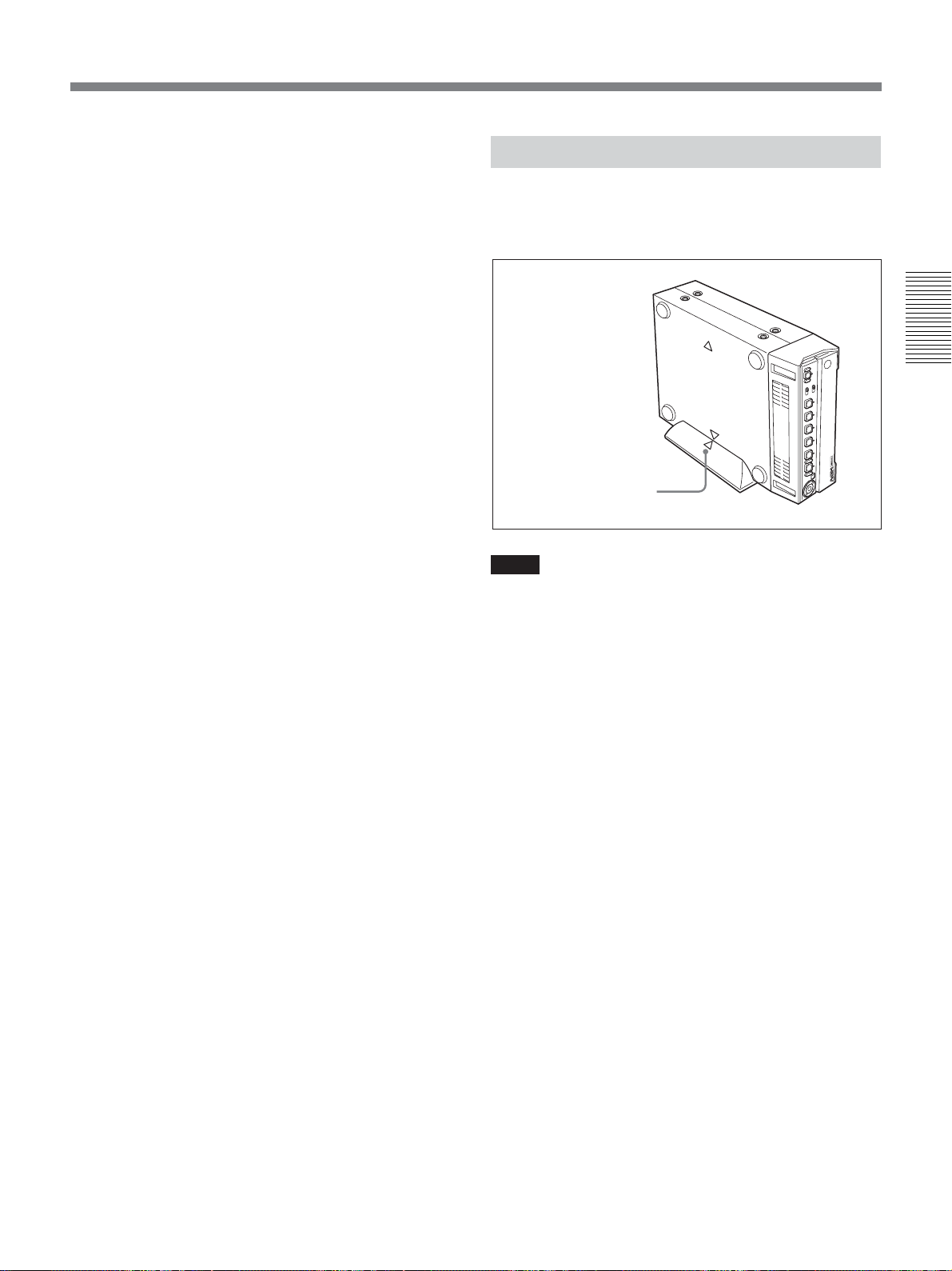
Installing the Unit Vertically
Put the unit into the supplied rack as illustrated below.
You can install it either standing on its left side or on
its right side.
Note on playback on other equipment
A tape recorded in HDV format using the unit cannot
be played back with the devices not compatible with
HDV1080i format. We recommend you to play back
the tape for checking the contents before you actually
play back the tape on other video equipment.
Chapter 2 Playback and Recording
Align the F on the unit
with the f on the rack.
Notes
•Be sure to use the supplied rack. Without the rack,
the unit may topple over and may be damaged or may
cause injury.
• Install the unit on a flat place.
•When inserting a cassette, hold the unit until it is
loaded into the unit. Otherwise the cassette may fall
out and the tape may be damaged.
For details on inserting a cassette, see “Notes on Power
Supply and Video Cassettes” on page 20.
• The name plate is located on the left side of the unit.
You may not see it when using the supplied rack.
Chapter 2 Playback and Recording 23
Playback
This section describes the connections and settings for
the playback and functions such as playback at various
speeds and searching for a specific scene on a recorded
tape.
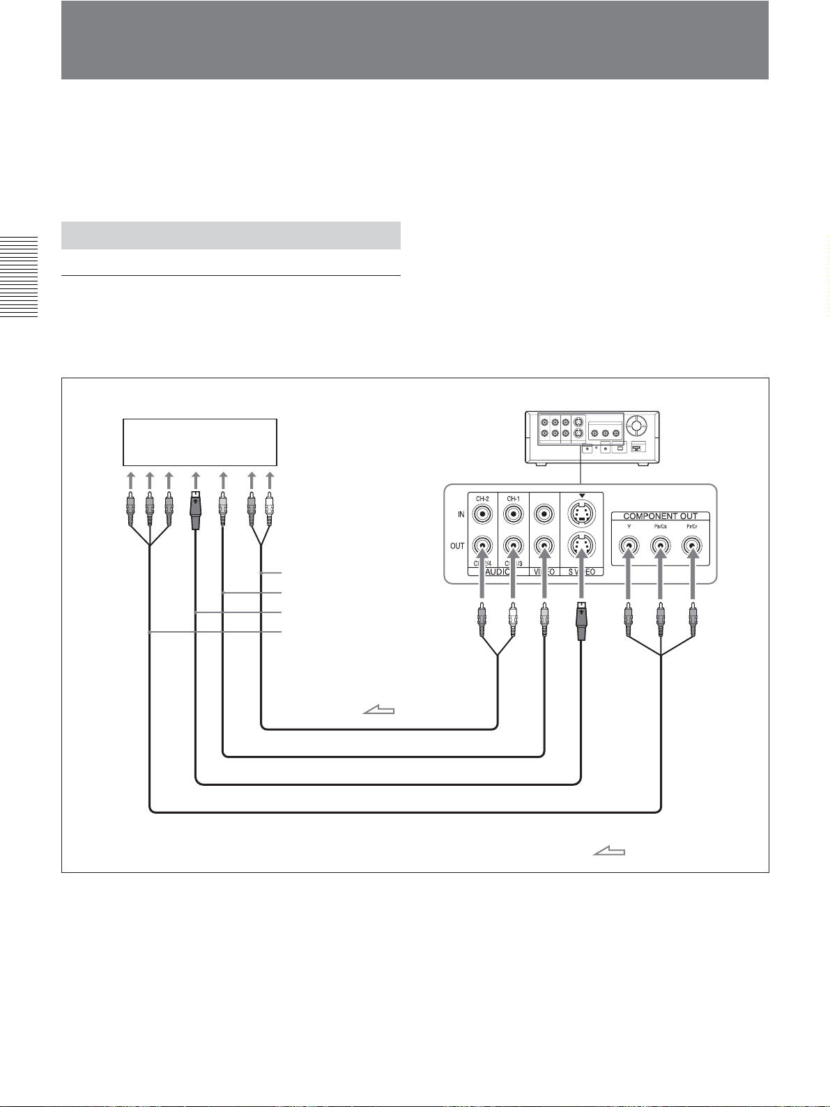
Connections for Playback
Connecting the unit to a monitor without
an i.LINK jack
Chapter 2 Playback and Recording
You can connect the unit to video monitor without an
i.LINK jack. Use the unit as follows.
Monitor
HVR-M15 (rear panel)
Audio input
Video input
S-video input
Component video input
Audio cable (Phono jack) (not supplied)
Video cable (not supplied)
S-video cable (not supplied)
24 Chapter 2 Playback and Recording
Component video cable (not supplied)
: Signal flow
 Loading...