

SONY HVR-1500 V1 Service Manual

DIGITAL HD VIDEOCASSETTE RECORDER
HVR-1500
ANALOG INPUT BOARD
HVBK-1505
SERVICE MANUAL
Volume 1 1st Edition

! WARNING
This manual is intended for qualified service personnel only.
To reduce the risk of electric shock, fire or injury, do not perform any servicing other than that
contained in the operating instructions unless you are qualified to do so. Refer all servicing to
qualified service personnel.
! WARNUNG
Die Anleitung ist nur für qualifiziertes Fachpersonal bestimmt.
Alle Wartungsarbeiten dürfen nur von qualifiziertem Fachpersonal ausgeführt werden. Um die
Gefahr eines elektrischen Schlages, Feuergefahr und Verletzungen zu vermeiden, sind bei
Wartungsarbeiten strikt die Angaben in der Anleitung zu befolgen. Andere als die angegeben
Wartungsarbeiten dürfen nur von Personen ausgeführt werden, die eine spezielle Befähigung
dazu besitzen.
! AVERTISSEMENT
Ce manual est destiné uniquement aux personnes compétentes en charge de l’entretien. Afin
de réduire les risques de décharge électrique, d’incendie ou de blessure n’effectuer que les
réparations indiquées dans le mode d’emploi à moins d’être qualifié pour en effectuer d’autres.
Pour toute réparation faire appel à une personne compétente uniquement.
HVR-1500

Für Kunden in Deutschland
Entsorgungshinweis: Bitte werfen Sie nur entladene
Batterien in die Sammelboxen beim Handel oder den
Kommunen. Entladen sind Batterien in der Regel dann,
wenn das Gerät abschaltet und signalisiert “Batterie
leer” oder nach längerer Gebrauchsdauer der Batterien
“nicht mehr einwandfrei funktioniert”. Um
sicherzugehen, kleben Sie die Batteriepole z.B. mit
einem Klebestreifen ab oder geben Sie die Batterien
einzeln in einen Plastikbeutel.
Voor de klanten in Nederland
Gooi de batterij niet weg maar lever deze in als klein
chemisch afval (KCA).
For the customers in Taiwan only
HVR-1500
1 (P)
CAUTION
ADVARSEL!
Lithiumbatteri-Eksplosionsfare ved fejlagtig
håndtering.
Udskiftning må kun ske med batteri
af samme fabrikat og type.
Levér det brugte batteri tilbage til leverandøren.
Danger of explosion if battery is incorrectly replaced.
Replace only with the same or equivalent type
recommended by the manufacturer.
Dispose of used batteries according to the
manufacturer’s instructions.
Vorsicht!
Explosionsgefahr bei unsachgemäßem Austausch
der Batterie.
Ersatz nur durch denselben oder einen vom
Hersteller empfohlenen ähnlichen Typ. Entsorgung
gebrauchter Batterien nach Angaben des
Herstellers.
ATTENTION
Il y a danger d’explosion s’il y a remplacement
incorrect de la batterie.
Remplacer uniquement avec une batterie du même
type ou d’un type équivalent recommandé par le
constructeur.
Mettre au rebut les batteries usagées conformément
aux instructions du fabricant.
ADVARSEL
Lithiumbatteri - Eksplosjonsfare.
Ved utskifting benyttes kun batteri som
anbefalt av apparatfabrikanten.
Brukt batteri returneres
apparatleverandøren.
VARNING
Explosionsfara vid felaktigt batteribyte.
Använd samma batterityp eller en likvärdig typ
som rekommenderas av apparattillverkaren.
Kassera använt batteri enligt gällande
föreskrifter.
VAROITUS
Paristo voi räjähtää jos se on virheellisesti
asennettu.
Vaihda paristo ainoastaan laitevalmistajan
suosittelemaan tyyppiin.
Hävitä käytetty paristo valmistajan ohjeiden
mukaisesti.
2 (P)
HVR-1500

Table of Contents
Manual Structure
Purpose of this manual ................................................................. 4
Related manuals ........................................................................... 4
Trademark ..................................................................................... 4
1. Installation
1-1. Operating Conditions ......................................................1-1
1-2. Power Supply ..................................................................1-2
1-2-1. Voltage and Power Requirements .........................1-2
1-2-2. Recommeded Power Cord ..................................... 1-2
1-3. Supplied Accessories ...................................................... 1-3
1-4. Optional Accessories ...................................................... 1-3
1-5. Matching Connectors/Cables ..........................................1-3
1-6. Input/Output Signals of the Connectors .........................1-4
1-7. Installation Setup and Adjustment ..................................1-6
1-7-1. Front Panel Setting ................................................1-6
1-7-2. System Adjustment After Installation ...................1-6
2. Service Overview
2-1. Location of Main Parts ...................................................2-1
2-1-1. Location of Printed Circuit Boards .......................2-1
2-1-2. Location of Main Mechanical Parts ...................... 2-4
2-2. Function and Location of Sensors ..................................2-5
2-3. Functions of Cassette ......................................................2-7
2-4. How to Take Out the Cassette Whose Tape is Slacked
(MANUAL EJECT) ........................................................ 2-8
2-5. Head Cleaning when Head Clogging Occurs ................. 2-8
2-6. Operating the VTR without a Cassette Tape .................. 2-9
2-7. Removing/Installing the Cabinets ................................. 2-10
2-7-1. Removal/Installation of the Top Panel ................2-10
2-7-2. Removal/Installation of the Bottom Plate ........... 2-10
2-7-3. Removal/Installation of the Front Panel .............. 2-11
2-7-4. Removal/Installation of the Rear Panel ............... 2-11
2-8. Removing/Installing the Cassette Compartment .......... 2-12
2-9. Function of Indicators on Circuit Boards .....................2-13
2-10. Switch Setting on Circuit Boards .................................2-14
2-11. Circuit Protection Parts (Fuse/IC Link) ........................2-15
2-12. Replacing NV-RAM and Memory Backup Battery .....2-16
2-13. Equipment and Fixtures List for Check/Adjustment ....2-18
2-13-1. Equipment for Check/Adjustment ....................... 2-18
2-13-2. Fixtures and Tools ...............................................2-19
2-14. Alignment Tapes ........................................................... 2-21
2-15. Tools for Board Extension ............................................2-23
2-16. Writing and Rewriting the PLD Internal Data .............. 2-25
2-17. Firmware Update .......................................................... 2-27
2-17-1. Upgrading the Version Using the
Fixture Board ....................................................... 2-27
2-17-2. Version Upgrade from a PC through RS-422 ..... 2-29
2-18. Internal Video Test Signal ............................................2-31
2-19. Service Action after Replacing or
Repairing the Board ......................................................2-31
2-20. Removing/Installing Flexible Card Wire ...................... 2-32
2-21. Unleaded Solder ............................................................ 2-35
2-22. Precautions for use of Condensation Sensor ................2-35
3. Error Messages
3-1. Alarm Display ................................................................. 3-1
3-1-1. Alarm Display when the Main Power is
Turned On .............................................................3-1
3-2. Error Codes .....................................................................3-3
3-2-1. Display of Previously Detected Error Codes ........ 3-5
3-2-2. Main Codes and Sub Codes ..................................3-6
3-2-3. Error Codes ...........................................................3-8
3-2-4. Possible Causes of Errors ....................................3-14
4. Maintenance Menu
4-1. Menu Structure ............................................................... 4-1
4-2. How to Operate Maintenance Menu ............................... 4-3
4-2-1. Location and Function of Switches .......................4-3
4-2-2. How to Enter the Maintenance Menu ...................4-3
4-2-3. How to Exit the Maintenance Menu .....................4-3
4-3. Contents of Maintenance Menu ......................................4-4
4-3-1. MENU DATA CONTROL ................................... 4-4
4-3-2. EDIT CHECK ....................................................... 4-7
4-3-3. SERVO CHECK ................................................... 4-9
4-3-4. SERVO ADJUST ................................................4-24
4-3-5. TAPE PATH ADJUST ........................................ 4-31
4-3-6. ELECTRICAL ADJUST ..................................... 4-32
HVR-1500
1

4-3-7. SERVICE SUPPORT .......................................... 4-40
4-3-8. OTHERS ............................................................. 4-42
5. Periodic Inspection and Maintenance
5-1. Periodic Inspection List .................................................. 5-1
5-2. Hours Meter ....................................................................5-2
5-2-1. Displaying Hours Meter Information ....................5-3
5-2-2. How to Reset Hours Meter ....................................5-4
5-3. Cleaning ..........................................................................5-5
5-3-1. Video Head Cleaning Procedure ...........................5-5
5-3-2. Tape Running Path Cleaning ................................. 5-5
5-3-3. Cassette Compartment Entrance Cleaning ............5-6
5-3-4. Cassette Compartment Shaft Cleaning ..................5-6
5-3-5. Cassette Guide Assembly Cleaning ......................5-6
6. Replacement of Mechanical Parts
6-1. General Information on Parts Replacement and
Adjustment ......................................................................6-1
6-1-1. Preparation Before Starting Parts Replacement .... 6-1
6-1-2. Drum Assembly ..................................................... 6-1
6-1-3. Grease ....................................................................6-1
6-1-4. Tightening Torque and Handling of Washers .......6-2
6-2. Drum Replacement ......................................................... 6-3
6-3. Brake Solenoid Replacement ..........................................6-8
6-4. Pinch Roller Replacement ............................................6-12
6-5. Elevator Cam Replacement .......................................... 6-14
6-6. Pinch Solenoid Assembly Replacement ....................... 6-16
6-7. Reel Motor (T) Assembly Replacement ....................... 6-18
6-8. Reel Motor (S) Assembly Replacement ....................... 6-23
6-9. M Stop Solenoid Replacement ..................................... 6-27
6-10. S Tension Regulator Assembly Replacement ............... 6-31
6-11. T Drawer Arm Assembly Replacement ........................ 6-34
6-12. TG1 Arm Assembly Replacement ................................6-36
6-13. TG8 Arm Assembly Replacement ................................6-38
6-14. Rail Assembly Replacement .........................................6-40
6-15. Capstan Motor Replacement ......................................... 6-46
6-16. Loading Motor Replacement ........................................ 6-48
6-17. Reel Shift Motor Assembly Replacement ....................6-49
6-18. MIC Assembly Replacement ........................................6-51
6-19. MIC Holder Assembly Replacement ............................6-55
6-20. HC Roller Assembly Replacement ...............................6-57
6-21. Head Cleaner Solenoid Replacement ........................... 6-60
6-22. Cassette Compartment Motor Replacement ................. 6-62
6-23. Removing/Installing the MD Assembly ....................... 6-64
6-24. LCD Replacement ........................................................6-65
6-25. Removing/Installing the Switching Regulator .............. 6-65
6-26. Removing/Installing the Mounted Board .....................6-66
6-26-1. Plug-in Board ...................................................... 6-66
6-26-2. CN-1968A Board ................................................ 6-66
6-26-3. CN-2905 Board ................................................... 6-66
6-26-4. DDE-22 Board ..................................................... 6-67
6-26-5. DR-428BG Board ................................................ 6-67
6-26-6. DVP-42 Board .....................................................6-68
6-26-7. HP-136 Board ...................................................... 6-69
6-26-8. HPR-20 Board .....................................................6-69
6-26-9. KY-614 Board .....................................................6-70
6-26-10. KY-616 Board .....................................................6-70
6-26-11. MB-1098 Board ................................................... 6-71
6-26-12. RP-133 Board and RT-10 Board .........................6-72
6-26-13. SDI-94 Board ...................................................... 6-73
6-26-14. SE-521G Board ................................................... 6-73
6-26-15. SE-522G Board ................................................... 6-74
6-26-16. SE-525G Board (LED Holder Assembly) ........... 6-74
7. Tape Path Alignment
7-1. General Information for Tape Path Adjustment ............. 7-1
7-2. Tape Path Adjustment ..................................................... 7-7
7-3. RF Switching Position Adjustment ..............................7-10
7-4. Tape Path Adjustment Confirmation ............................7-13
7-5. Search Forward (x5) Waveform Check ....................... 7-14
7-6. Search Reverse (x5) Waveform Check ........................7-15
7-7. RF Waveform Raiseup Check ...................................... 7-16
7-8. Tape Curl Check at Tape Guide ................................... 7-17
8. Electrical Alignment
8-1. Electrical Alignment Overview ...................................... 8-1
8-1-1. Precautions ............................................................ 8-1
8-1-2. Outline of Electrical Alignment ............................ 8-1
8-1-3. Equipment and Fixture ..........................................8-1
8-2. Audio Adjustment ........................................................... 8-2
8-2-1. Audio Output Level Adjustment ...........................8-2
8-2-2. Audio EE Level Adjustment ................................. 8-2
2
HVR-1500

8-3. Video Adjustment ...........................................................8-3
8-3-1. Preparation in the 59.94 Hz Mode ........................8-3
8-3-2. HCK Frequency Adjustment .................................8-4
8-3-3. HD HCK Frequency Adjustment .......................... 8-4
8-3-4. SYNC Phase Adjustment ...................................... 8-5
8-3-5. CHARACTER DC Adjustment ............................8-6
8-3-6. CF DET CENTER Adjustment .............................8-6
8-3-7. S VIDEO Y Level Adjustment .............................. 8-7
8-3-8. COMPOSITE Video Level Adjustment ................ 8-7
8-3-9. COMPOSITE Burst Level Adjustment .................8-8
8-3-10. S VIDEO Chroma Level Adjustment .................... 8-8
8-3-11. COMPONENT SD Y Level Adjustment .............. 8-9
8-3-12. COMPONENT HD Y Level Adjustment .............. 8-9
8-3-13. COMPONENT Y REC Level Adjustment .......... 8-10
8-3-14. COMPONENT R-Y REC Level Adjustment ...... 8-10
8-3-15. COMPONENT B-Y REC Level Adjustment ...... 8-11
8-3-16. COMPOSITE Y REC Level Check .................... 8-11
8-3-17. COMPOSITE Chroma REC Level Check .......... 8-12
8-3-18. S VIDEO Y REC Level Check ........................... 8-12
8-3-19. S VIDEO Chroma REC Level Check ................. 8-13
8-3-20. Adjustment in the 50 Hz Mode ........................... 8-14
8-4. SDI Free-running Adjustment ......................................8-15
8-5. LCD Adjustment ........................................................... 8-16
8-5-1. Contrast Adjustment ............................................8-16
8-5-2. V-COM Adjustment ............................................8-16
8-5-3. Sample Hold Timing Adjustment ....................... 8-17
8-5-4. White Balance Adjustment .................................. 8-18
8-6. Adjustment Related Parts Layout Diagram .................. 8-19
HVR-1500
3

Purpose of this manual
Related manuals
Manual Structure
This manual is the Service Manual Volume 1 for the digital HD videocassette
recorder HVR-1500, the option board Analog Input Board HVBK-1505.
This manual contains the maintenance information of this equipment, and servicing
information necessary for parts replacement and adjustments.
In addition to this Service Manual Volume 1, the following manuals are provided.
..
. Operation Instructions
..
HVR-1500 (Supplied with HVR-1500 )
Part number : 3-993-538-1X
HVBK-1505 (Supplied with HVBK-1505)
Part number : 3-993-605-0X
..
. CD-ROM Manual (Supplied with SY model)
..
This manual contains the Japanese, English, French, German, Italian, and Spanish
operating instructions (PDF).
Part number : 3-993-560-0X
Trademark
..
. Service Manual Volume 2 (Not Supplied with equipment)
..
Contains the semiconductor pin assignments, parts lists, block diagrams, board
layouts and schematic diagrams.
Part number : 9-968-317-0X
..
. “Semiconductor Pin Assignments” CD-ROM (Available on request)
..
This “Semiconductor Pin Assignments” CD-ROM allows you to search for
semiconductors used in Broadcast and Professional equipment.
The service manual volume 2 contains a complete list of semiconductors and their
ID Nos., and thus should be used together with the CD-ROM.
Part number: 9-968-546-06
Trademark or registered trademark used in this manual is follows.
. Windows is a registered trademark of Microsoft Corporation.
4
HVR-1500

Section 1
Installation
Be sure to install the HVR-1500 in location satisfying the required operational environment described
below to assure the HVR-1500 superior performance and to maintain the excellent serviceability and
accessibility.
1-1. Operating Conditions
c
Good air circulation is essential to prevent internal heat build-up. Place the unit in location with sufficient
air circulation.
Do not block the ventilation holes of the cabinet and the front and rear panels.
Operating temperature: 5 dC to 40 dC
Operating humidity: Less than 80 %
Storage temperature: _20 dC to 60 dC
Locations to avoid:
. Areas where the unit will be exposed to direct sunlight of any other strong lights.
. Areas near heat sources.
. Dusty areas or areas subject to vibration.
. Areas with strong magnetic field.
. Areas with much electrical noise.
. Areas with much static electricity.
. Areas windtight.
Tilt allowance: Within 30d (Do not slant the front and rear of the unit more than 30d.)
c
Fix the unit securely to avoid drop when the unit is operated at not-horizontal place.
HVR-1500
1-1
1-2. Power Supply
1-2-1. Voltage and Power Requirements
For customers in the U.S.A. and Canada:
1 Power cord 125 V 10 A (2.4 m): ! 1-551-812-11
2 Plug holder (Brown): 3-613-640-01
This unit’s power line has a switching regulator.
c
Be sure to operate the unit within the range of following
power voltage.
Power voltage: AC 100 to 240 V ±10 %
Power frequency: 50 Hz or 60 Hz
Power consumption: 60 W
Rush current: Power voltage 100 V IN: 12 A
Power voltage 240 V IN: 34 A
n
AC power supply is required a capacity which is commensurate with rush current.
If the capacity of the AC power supply is not enough, the
breaker of AC power of a supply side may operate or this
unit may not operate normally.
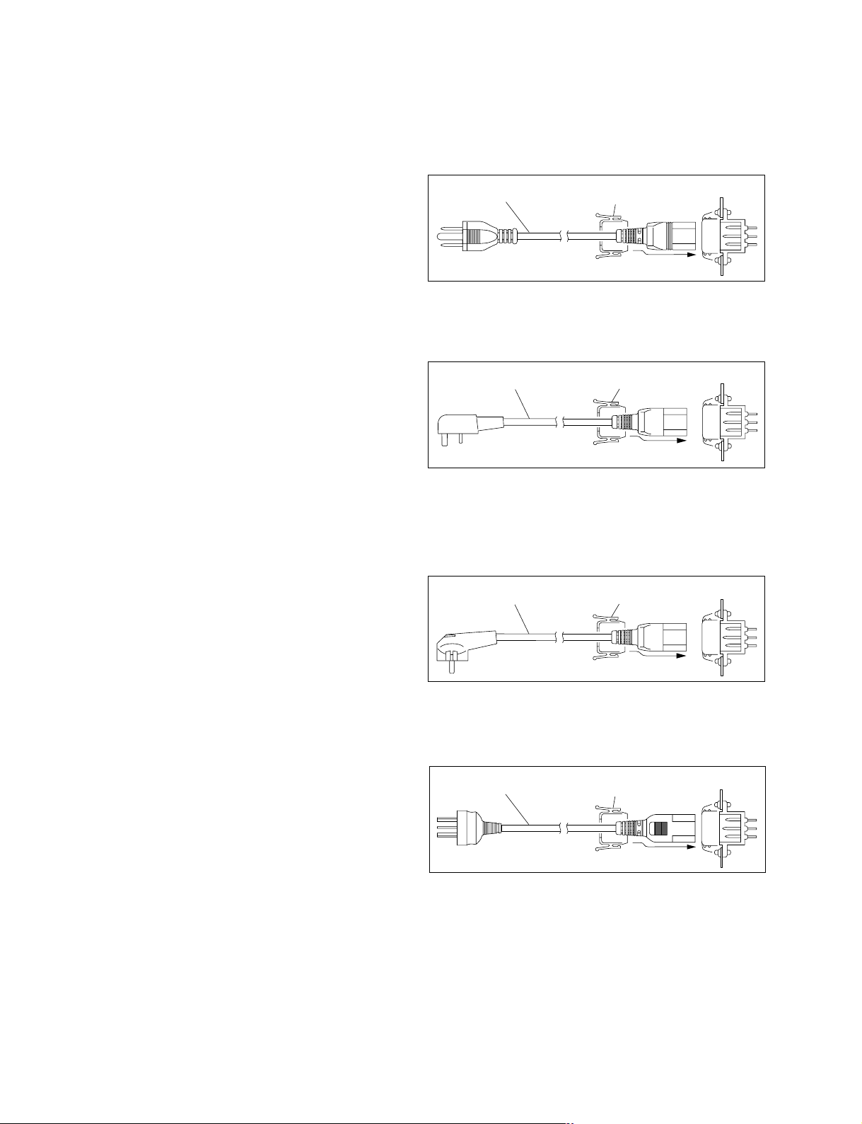
1-2-2. Recommeded Power Cord
This unit does not come with a power cord.
To get a power cord, please contact your local Sony Sales
Office/Service Center.
1
2
AC inlet
For customers in the United Kingdom:
1 Power cord 250 V 10 A (2.4 m): ! 1-782-165-11
2 Plug holder (Brown): 3-613-640-01
21
AC inlet
For customers in European countries except the United
Kingdom:
1 Power cord 250 V 10 A (2.0 m): ! 1-551-631-15
2 Plug holder (Brown): 3-613-640-01
21
AC inlet
w
. Use the approved Power Cord (3-core mains lead)/
Appliance Connector/Plug with earthing-contacts that
conforms to the safety regulations of each country if
applicable.
. Use the Power Cord (3-core mains lead)/Appliance
Connector/Plug conforming to the proper ratings (Voltage, Ampere).
If you have questions on the use of the above Power Cord/
Appliance Connector/Plug, please contact your local Sony
Sales Office/Service Center.
w
. Never use an injured power cord.
For customers in the China:
1 Power cord 250 V 10 A (1.8 m): ! 1-783-481-41
2 Plug holder (Brown): 3-613-640-01
1
2
AC inlet
If the unit is used in the area except above, please contact
your local Sony Sales Office/Service Center.
1-2
HVR-1500

1-3. Supplied Accessories
. Operating instructions : 1
. Operating instructions (CD-ROM) : 1
1-4. Optional Accessories
. AC power cord
. Analog input board : HVBK-1505
. 9-pin remote conrtrol cable : RCC-5G (Length : 5 m (16 ft))
. Remote control unit : DSRM-10
. Digital video cassette : PDV-184*/124*/94*/64* (Standard-size (L) )
PDVM-40*/32*/22*/12* (Mini-size (S) )
PHDV-276DM*/186DM*/124DM*/64DM* (Standard-size (L) )
PHDVM-63DM* (Mini-size (S) )
n
The * in each model name is actually “ME” (indicating that a cassette
memory is contained), “N” (indicating that no cassette memory is
contained) or “MEM” (indicating a master tape).
. Cleaning cassette tape : PDV12CL (Standard size), PDVM12CL (Mini size)
1-5. Matching Connectors/Cables
When external cables are connected to the connector on a connector panel during maintenance, the
following connectors, cables (or their equivalents) must be used.
Connectors on HVR-1500 Side Matching connector/cable
Panel indication Designation Sony Part No. Remark
ANALOG IN BNC, MALE 1-560-069-11
REF. VIDEO IN (SD/HD)
TC IN When HVBK-1505
VIDEO IN is attached
AUDIO IN CH-1/3, 2/4 XLR 3P, MALE 1-508-083-11 When HVBK-1505
is attached
ANALOG OUT BNC, MALE 1-560-069-11
TC OUT
VIDEO OUT
MONITOR AUDIO PIN PLUG Standard Product
AUDIO OUT CH-1/3, 2/4 XLR 3P, FEMALE 1-508-084-11
HDV/DV IEEE1394 6P (1 m) 1-782-408-21
IEEE1394 6P (3.5 m) 1-791-184-11
SDI IN BNC, MALE 1-560-069-11
SDI OUT1, 2 BNC, MALE 1-560-069-11
HD-SDI OUT 1, 2 BNC, MALE 1-560-069-11
AUDIO I/O (AES/EBU) BNC, MALE 1-560-069-11
IN CH-1/2, 3/4
OUT CH-1/2, 3/4 BNC, MALE 1-560-069-11
REMOTE D-SUB 9P, MALE 1-560-651-11
HVR-1500
1-3

1-6. Input/Output Signals of the Connectors
INPUT
REF. VIDEO IN (SD/HD) : BNC x 2 (loop-through with 75 Z automatic terminator)
SD composite sync, black burst: 0.286 V p-p (525/60) or 0.3 V p-p (625/
50), 75 Z, negative sync
HD tri-level sync: 0.3 V, 75 Z, negative sync
VIDEO IN: BNC x 4 (When HVBK-1505 is attached)
Composite
Y/S-Y/CPST and 1 loop-through connector with 75 Z automatic
terminator: 1.0 V p-p, 75 Z, negative sync
Component
Y/S-Y/CPST: 1.0 V p-p, 75 Z, negative sync
R-Y/S-C and B-Y: 0.7 V p-p (75 % color bars for 525/59.94 or 100%
color bars for 625/50) , 75 Z
S-video
Y/S-Y/CPST: 1.0 V p-p, 75 Z, negative sync
R-Y/S-C: 0.286 V p-p (525/59.94) or 0.3 V p-p (625/50), 75 Z (burst
level)
SDI IN: BNC x 1
Serial digital interface format (270 Mbps), SMPTE 259M/ITU-R BT.656
AUDIO IN: XLR 3-pin x 2, FEMALE (When HVBK-1505 is attached)
+4/0/_3*/_6 dBm , high impedance, balanced
*
: For 625/50 only
AUDIO I/O (AES/EBU) : BNC x 2
Complying with AES-3id-1995
TC IN: BNC x 1, SMPTE timecode (525/59.94) or EBU timecode (625/50)
0.5 V p-p to 18 V p-p, 3.3 kZ, unbalanced
HDV/DV: 6-pin IEEE 1394 connector x 1
OUTPUT
VIDEO OUT: BNC x 3
Composite
Y/CPST: 1.0 V p-p, 75 Z, negative sync
Component (SD)
Y/CPST: 1.0 V p-p, 75 Z, negative sync
Pr/R-Y/S-C and Pb/B-Y/S-Y: 0.7 V p-p (75% color bars for 525/59.94
or 100% color bars for 625/50),75 Z
Component (HD)
Y: 1.0 V p-p, 75 Z, negative sync
Pr, Pb: 0.7 V p-p, 75 Z
S-video
Pb/B-Y/S-Y: 1.0 V p-p, 75 Z, negative sync
Pr/R-Y/S-C: 0.286 V p-p (525/59.94) or 0.3 V p-p (625/50), 75 Z (burst
level)
Monitor video output
BNC x 1
(SUPER) CPST: 1.0 V p-p, 75 Z, negative sync
SDI OUT: BNC x 2
Serial digital interface format (270 Mbps), SMPTE 259M/ITU-R BT.656
1-4
HVR-1500
HD-SDI OUT: BNC x 2
Serial digital interface format (1.485, 1.485/1.001 Gbps), SMPTE 292M
AUDIO OUT: XLR 3-pin x 2, MALE
*
+4/0/_3
*
: For 625/50 only
/_6 dBu, 600 Z loading, low impedance, balanced
MONITOR AUDIO: Phono jack x 1
_∞ to _11 dBu ±1 dB (_20 dBFS) /_9 dBu ± 1 dB (_18 dBFS), 47 kZ,
unbalanced
PHONES: Stereo phone jack x 1
_∞ to _13 dBu (_20 dBFS) /_11 dBu (_18 dBFS), 8 Z, unbalanced
AUDIO I/O (AES/EBU) : BNC x 2
Complying with AES-3id-1995
TC OUT: BNC x 1
SMPTE timecode (525/59.94), EBU timecode (625/50)
2.2 V p-p ±3 dB (when 600 Z terminated) , unbalanced
HDV/DV: 6-pin IEEE 1394 connector
Remote control connectors
CONTROL-S: Stereo minijack x 1
HDV/DV: 6-pin IEEE 1394 connector
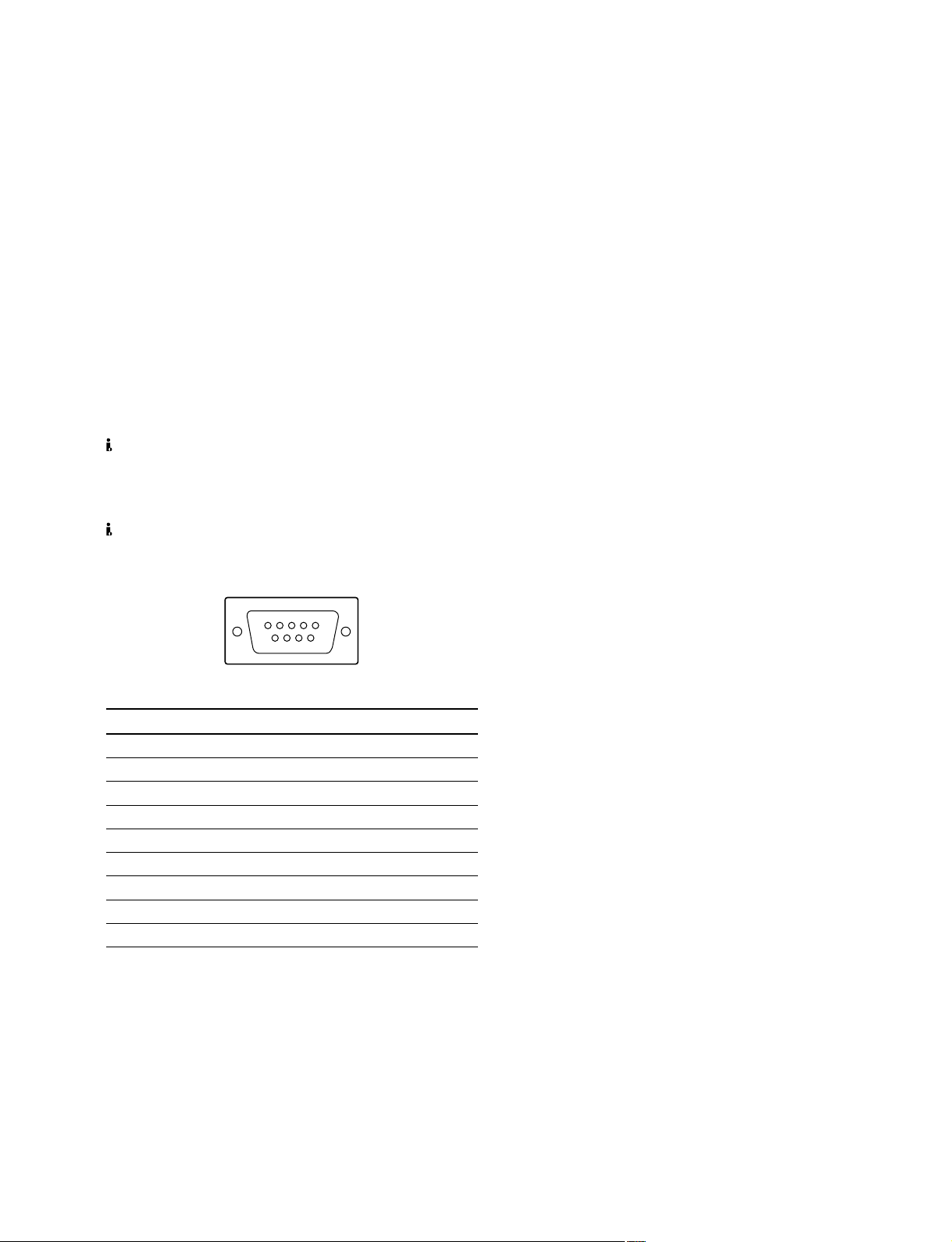
REMOTE (D-sub 9-pin : MALE)
5
9
__
_ EXT VIEW
__
Pin No. Controlling Device Controlled Device
1 FRAME GROUND FRAME GROUND
2 RECEIVE A TRANSMIT A
3 TRANSMIT B RECEIVE B
4 TRANSMIT COMMON RECEIVE COMMON
5 PRIORITY IN PRIORITY OUT
6 RECEIVE COMMON TRANSMIT COMMON
7 RECEIVE B TRANSMIT B
8 TRANSMIT A RECEIVE A
9 FRAME GROUND FRAME GROUND
1
6
__
_
__
HVR-1500
1-5
1-7. Installation Setup and Adjustment
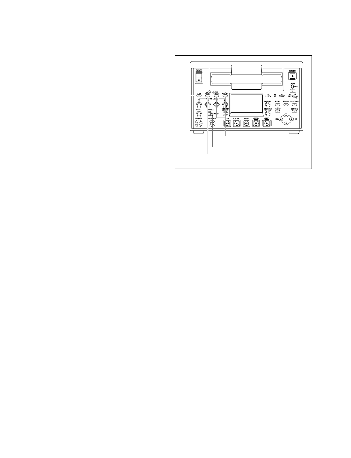
1-7-1. Front Panel Setting
Front panel
1. i.LINK INPUT SELECT button setting
i.LINK : HDV: Video and audio signals in HDV
format
i.LINK : DV
i.LINK : DVCAM
*
: The display follows the recording format setting in
the REC FORMAT menu item. (Refer to the
operating instructions for details)
2. VIDEO INPUT SELECT button setting
COMPOSITE: Composite video signal
S VIDEO: S-video (separated Y and C)
COMPONENT SD: Component video signals
SDI: SDI video signal
SG: Video test signal
3. AUDIO INPUT SELECT button setting
ANALOG: Analog audio signal
AES/EBU: Digital audio signal in AES/
SDI: Digital audio signal in SDI
SG: Audio test signal
*
: Video and audio signals in DV
format
*
: Video and audio signals in
DVCAM format
(When HVBK-1505 is attached)
signals (When HVBK-1505 is
attached)
(When HVBK-1505 is attached)
(When HVBK-1505 is attached)
EBU format
format
Layout of switch and buttons on the front panel
3. CH1 1/2 button
CH2 3/4 button
4. VARIABLE switch
2. VIDEO button
1. i.LINK button
1-7-2. System Adjustment After Installation
Observe the following precautions when this equipment is
used for editing system.
. The REF. VIDEO IN requires video signal which is in
conformity with the RS-170A (525/60).
. Adjust the sync phase of this equipment to the system
sync with [SYNC PHASE] control of the setup menu.
. Adjust the SCH phase of this equipment to the system
SCH with [SUB CARRIER] control of the setup menu.
. When this unit is connected to a switcher that does not
have the sync switching function, the SYNC/BURST
level adjustment is required.
4. AUDIO VARIABLE switch setting
PRESET : Sets both the REC and PB levels
to the normal level.
REC : Sets the REC audio level of the
channels respectively with the
CH-1/2/3/4 knobs.
PB : Sets the PB audio level of the
channels respectively with the
CH-1/2/3/4 knobs.
1-6
HVR-1500
Service Overview
!-
0
9
7
3
5
4
1
2
6
Switching regulator
!]
!=
![
8
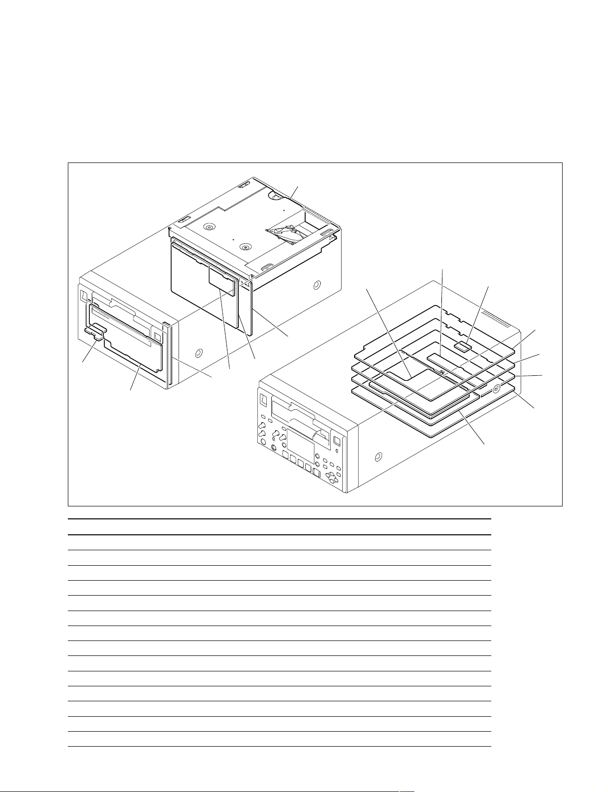
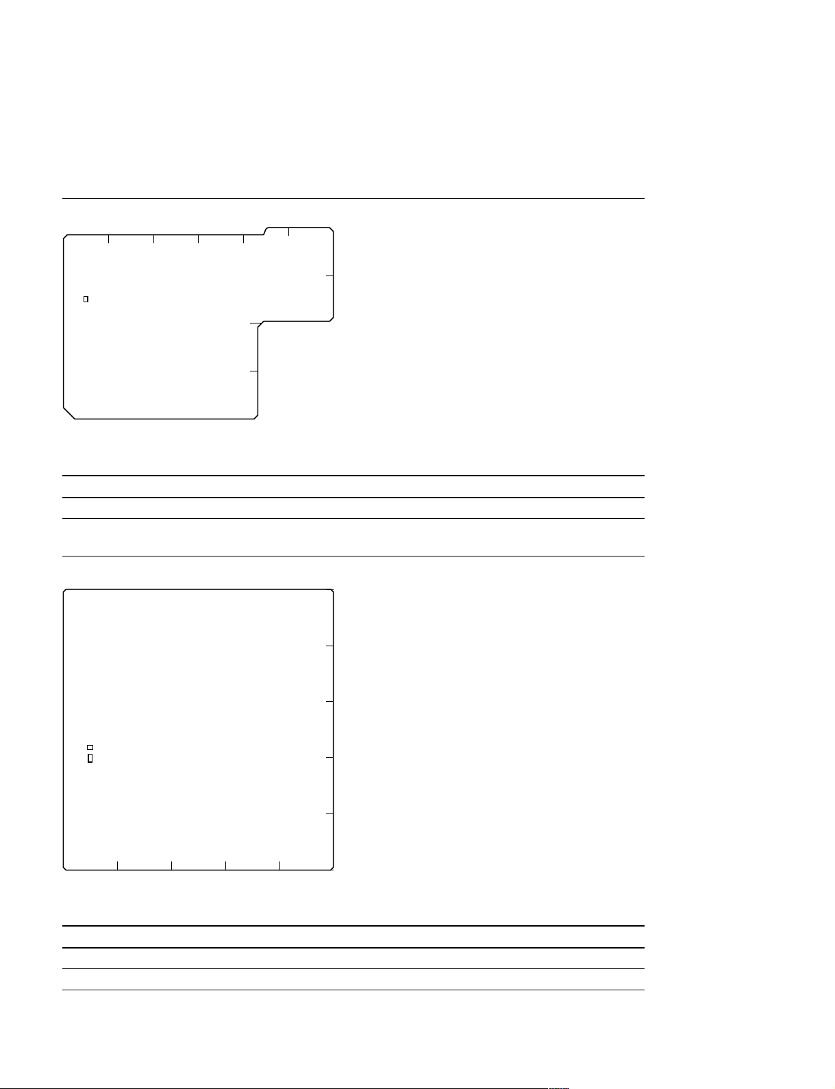
2-1. Location of Main Parts
2-1-1. Location of Printed Circuit Boards
Section 2
Board name Circuit function
1 MB-1098 Motherboard
2 RP-133 RF REC/PB, ATF Detection
3 HP-136 Headphone, Remote Control
4 KY-614 Key Board
5 KY-616 Graphics Renderer
6 RT-10 HDV Equalizer
7 CN-1968A HDV/DV Connector Board
8 DDE-22 (HVBK-1505) Analog Video/Audio Input Board
9 AVP-7 Analog Video/Audio Output Board
!/ SDI-94 Digital Input/Output Board
!- SSS-12 System/Servo Control
!= CN-2905 Intermediate Board
![ DVP-42 DV Video/Audio Digital Process
!] HPR-20 HDV Video/Audio Digital Process
HVR-1500
2-1
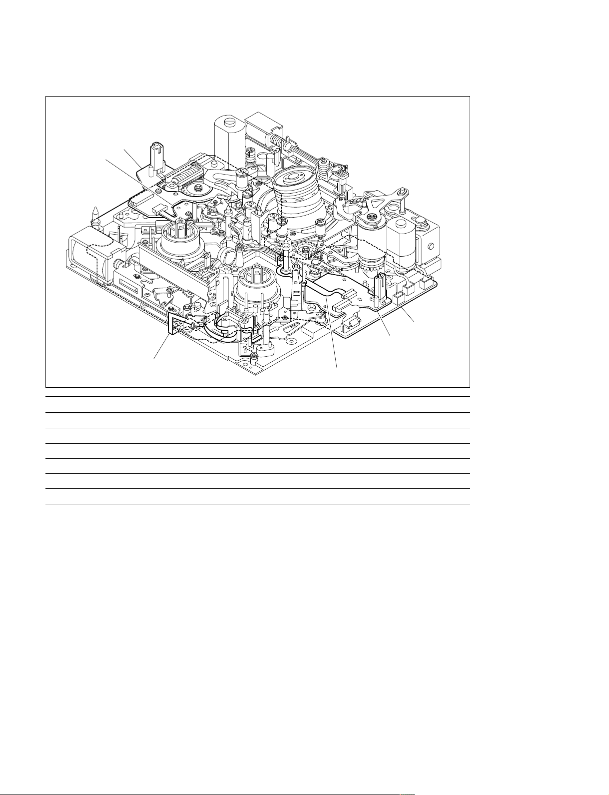
Locations of mechanism deck
1
2
6
5
3
Board name Circuit function
1 SE-521G Threading Mode Sensor, Tape End Sensor, Loading Motor FG Sensor
2 SE-538G Tension Sensor
3 CN-1863 REC INHIBIT Sensor, MIC Terminal
4 SE-525G Tape Top/End LED
5 SE-522G Tape Top Sensor, Reel Position Sensor
6 DR-428BG Drum/Reel/Capstan Control Board
4
2-2
HVR-1500
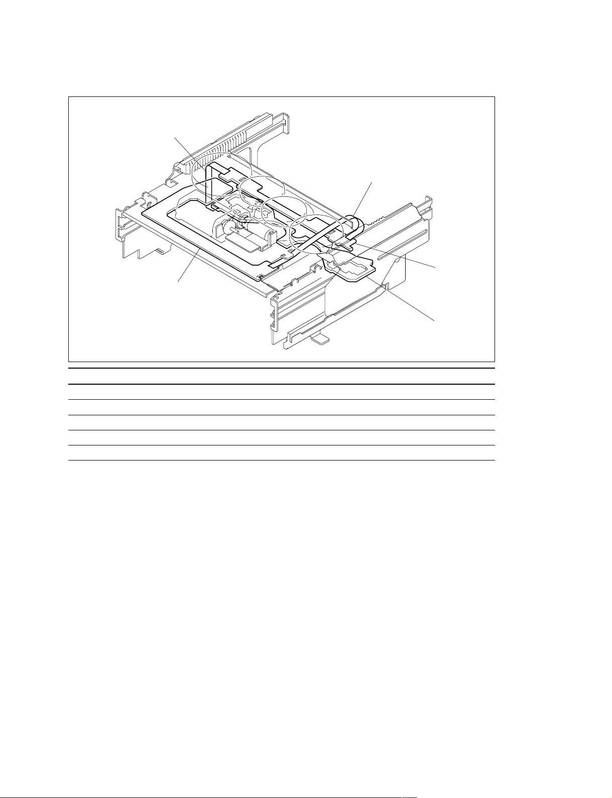
Locations of cassette compartment
1
2
5
4
3
Board name Circuit function
1 CN-2021G Intermediate Board
2 CC-83G Cassette Compartment Mode Detection, Intermediate Board
3 CC-85G Cassette In Detection
4 CC-84G Cassette Type Detection
5 CN-2022G Intermediate Board
HVR-1500
2-3
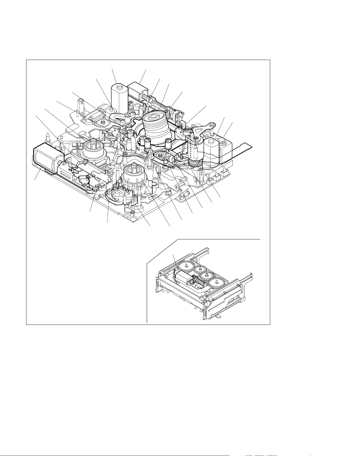
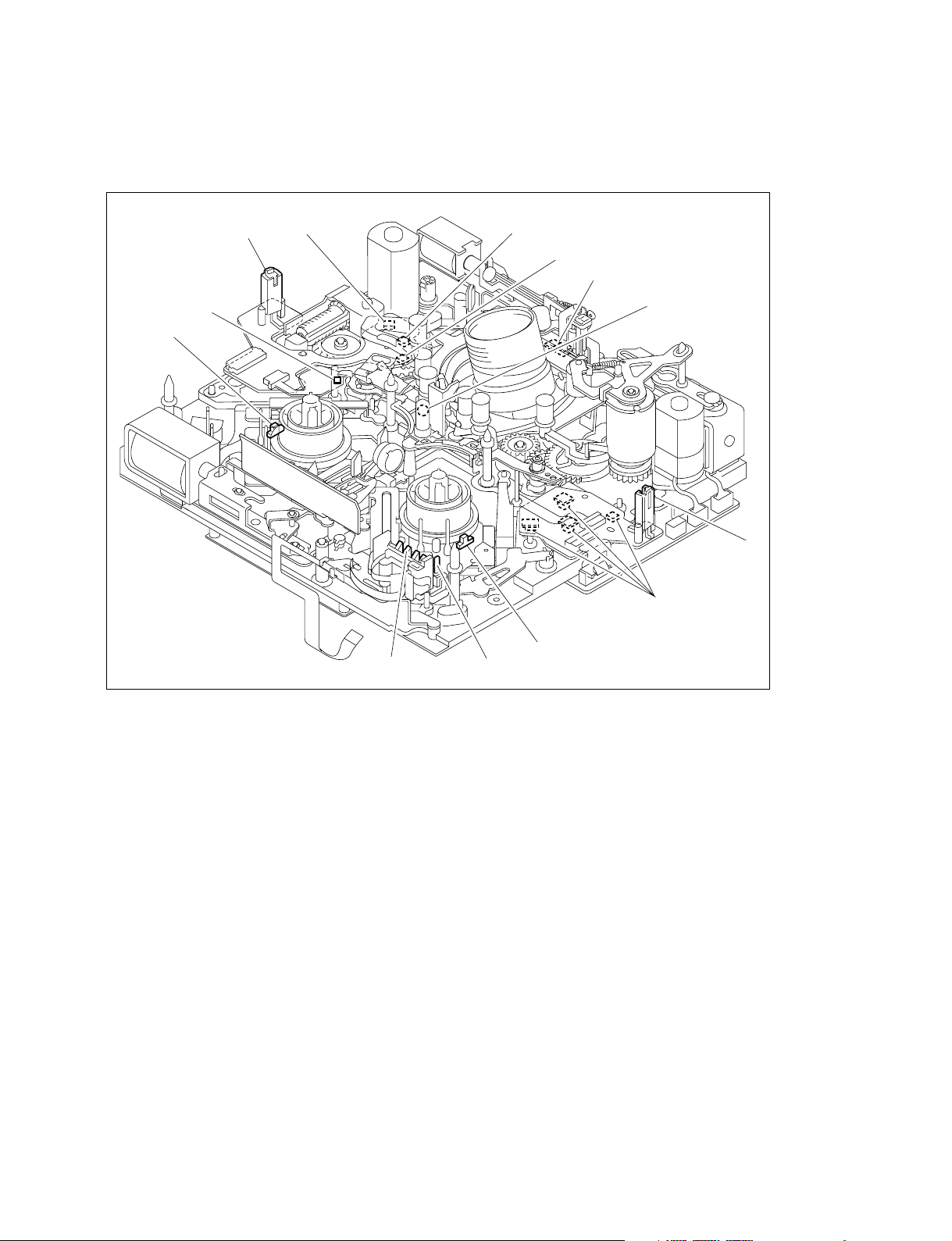
2-1-2. Location of Main Mechanical Parts
8
7
6
5
4
9
3
0
2
1
!-
!=
@]
@[
@=
@-
@/
!.
!,
!'
!;
!\
!]
![
1 Head cleaning solenoid
2 Loading motor
3 TG1 arm assembly
4 Shuttle (left) assembly
5 S tension regulator assembly
6 S reel motor
7 S brake assembly
8 Brake solenoid
9 M stop solenoid assembly
!/ T brake assembly
!- MIC assembly
!= MIC holder assembly
![ T reel motor
@\
!] Shuttle (right) assembly
!\ T drawer arm assembly
!; TG8 arm assembly
!' Capstan motor
!, Elevator cam
!. Pinch solenoid assembly
@/ Reel shift motor
@- Pinch roller
@= HC roller assembly
@[ Drum assembly
@] Rail assembly
@\ Cassette compartment motor assembly
2-4
HVR-1500
2-2. Function and Location of Sensors
(1) Mechanism deck
!-
!/
!=
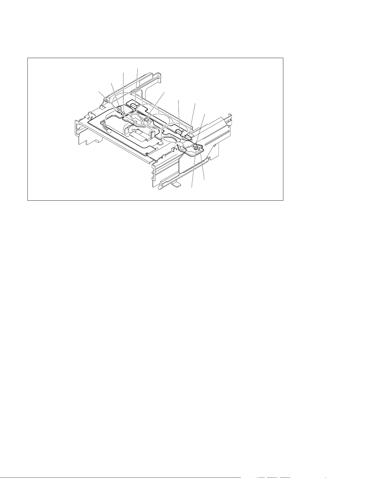
(2) Cassette compartment
1 S3
2 PH1
2 PH2
2 PH3
3 PH4
1 S1
1 S2
3 PH5
3 PH7
3 PH6
1 The sensors S1, S2 and S3 discriminate the inserted cassette type among the mini, M, standard
cassettes and the cassette adaptor for DVCPRO by on/off of the sensors.
2 The sensors PH1, PH2 and PH3 detect the movement of a cassette compartment by their combina-
tion.
3 The sensors PH4 and PH5 detect that a mini cassette got inserted.
The sensors PH4 and PH6 detect that a M cassette got inserted.
The sensors PH4 and PH7 detect that a standard cassette got inserted.
2-6
HVR-1500
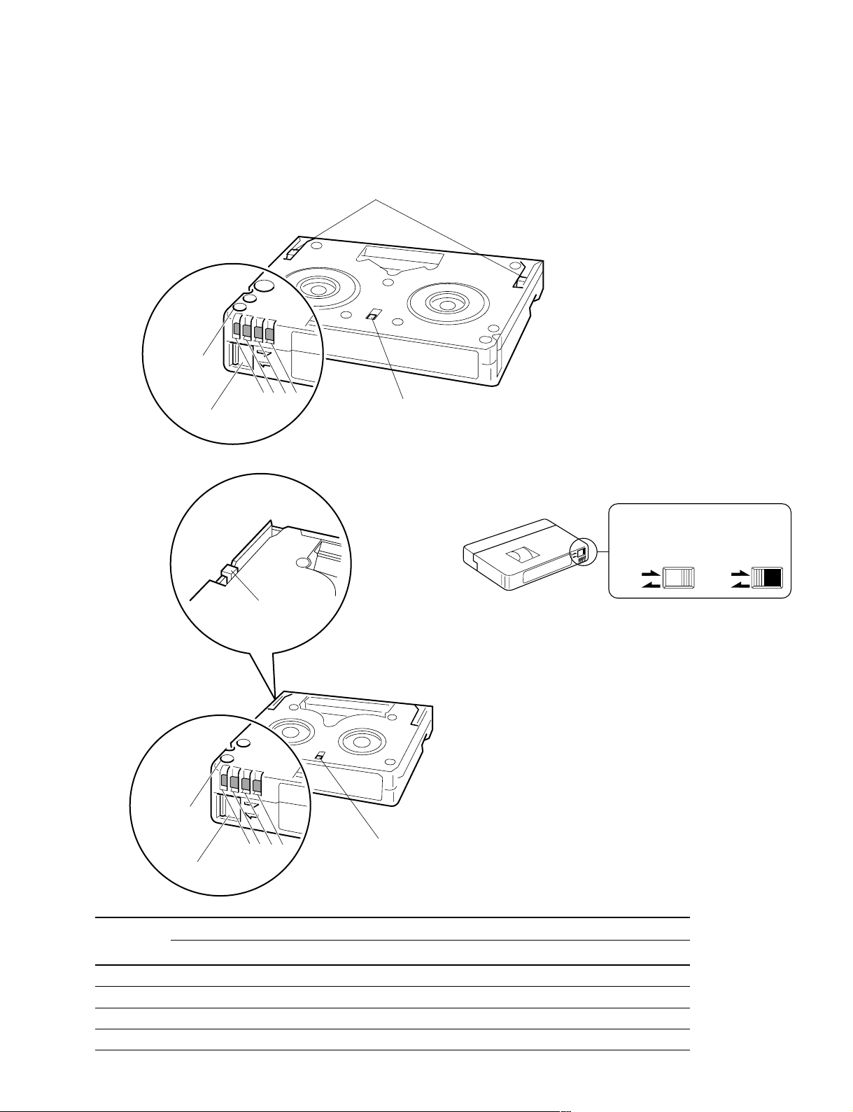
2-3. Functions of Cassette
Standard cassette, M cassette
Cassette cover release claw
Record proof
hole
4
1
32
Record proof plug
Mini cassette Hole and plug for record proof
Reel rotation stopper
Record enable Record protect
REC
SAVE
Cassette cover release claw
. This plug controls the record proof
switch according to open or close
position.
Record proof
hole
4
32
1
Reel rotation stopper
Record proof plug
Pin No. Function
Equipped with built-in memory Not equipped with built-in memory
1 +DC Detecting tape thickness
2 DATA Detecting tape type (Example: ME/MP)
3 CLOCK Detecting tape application (Example: consumer/professional)
4 GND _
REC
SAVE
HVR-1500
2-7
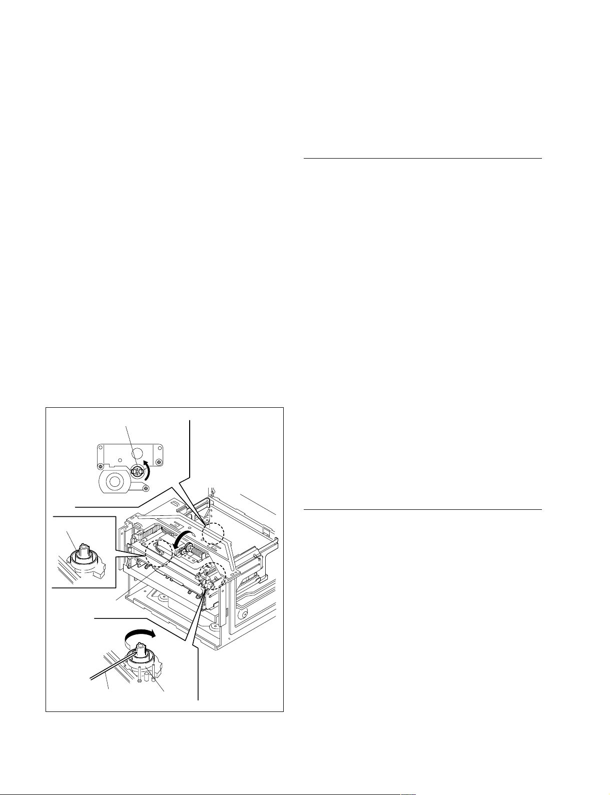
2-4. How to Take Out the Cassette
Whose Tape is Slacked (MANUAL
EJECT)
(1) Turn the power off.
(2) Remove the top panel. (Refer to Section 2-7-1.)
(3) Remove the front panel. (Refer to Section 2-7-3.)
(4) Turn the manual eject gear A (red) in the arrow
direction with a phillips screwdriver while pressing the
gear. When the tape comes to slack, turn the reel table
from the front side utilizing a skewer and wind the
tape.
n
In a case of standard cassette and M cassette :
Turn the reel table (T)
In a case of mini cassette :
Turn the reel table (S)
(5) Repeat step (4) until each guide comes to the unthread-
ing end position and furthermore the tape completely
returns into the cassette.
(6) Turn the manual eject gear B (red) in the arrow
direction until the cassette compartment completely
comes into cassette out state.
Manual eject gear A (red)
2-5. Head Cleaning when Head Clogging
Occurs
Clean the video head as follows when the video head gets
dirty.
Procedure to Use the Cleaning Cassette
n
Use only the cleaning cassette tape as follows.
If another cleaning cassette tape is used, abnormal abrasion
or breakage of the video head could occur.
Cleaning cassette tapes :
PDV12CL (Standard)
PDVM12CL (Mini)
1. Insert the specific cleaning cassette tape in this unit.
The unit is automatically set in the PLAY mode and
the cleaning tape starts running.
Confirm that the [PLAY] key lights and the display
appears.
2. The cleaning cassette tape is automatically ejected
after running for 10 seconds.
n
Do not rewind the cleaning cassette tape to use it
again.
Reel table (S)
Manual
eject gear B (red)
Skewer
3. Make sure that the head is no longer dirty.
If the video head is still dirty after step 2 above, clean
the video head as follows.
Procedure to Use the Cleaning Cloth
1. Soak the cleaning cloth with cleaning liquid and bring
it into contact lightly with the video head.
2. Turn the upper drum slowly by hand in the rotating
direction of the head (counterclockwise when viewed
from the top) to clean the video head.
m
. Never move the cleaning cloth in the vertical direction
against the video head because it may break the head.
. Turn the power switch off when cleaning the video head.
Reel table (T)
2-8
HVR-1500

2-6. Operating the VTR without a
Mini M STD
Cassette Tape
The VTR can be operated without a cassette tape by the
following switch setting.
Switch Setting
1. Remove the cassette compartment from this unit.
2. Turn on switches S401-4 of the SSS-12 board.
3. Then turn on the main power.
Operating Method
REC
While pressing the record proof sensor on the right side of
the T side reel table, press both the [PLAY] key and the
[REC] key.
The pinch roller is pressed against the capstan shaft to
enter REC status.
When the record proof sensor is released, the REC status is
released and the recorder returns to PLAY status.
Unthreading
Press the [EJECT] key.
Each guide moves to the specified position to complete the
unthreading.
Threading
While pressing the S/T reel motors, press the [STOP] key.
The upper drum rotates, threading ring rotates. The unit
enters the threading mode.
The tension arm and the threading ring move to the
specified position, then the threading is completed.
This condition in which the threading is completed is
referred to as the STOP status.
PLAY
Press the [PLAY] key.
The pinch roller is pressed against the capstan shaft to
enter the PLAY status.
When the [PLAY] key is pressed during threading, the
pinch roller is pressed against the capstan shaft to enter the
PLAY status after the threading has completed.
FF
Press the [F|FWD] key.
The pinch roller is pressed against the capstan shaft to set
the FWD.SEARCH to five-times speed.
Reel position selection
Press the SET (YES) key on the control panel.
Reel position will be changed as shown below in accordance with the number of pressing the SET (YES) key.
n
Make sure to turn off switches S401-4 on the SSS-12
board after the adjustment.
REW
Press the [REW] key.
The pinch roller is pressed against the capstan shaft to set
REV.SEARCH to five-times speed.
HVR-1500
2-9
2-7. Removing/Installing the Cabinets
n
Before removing the cabinets, be sure to turn off the main
power.
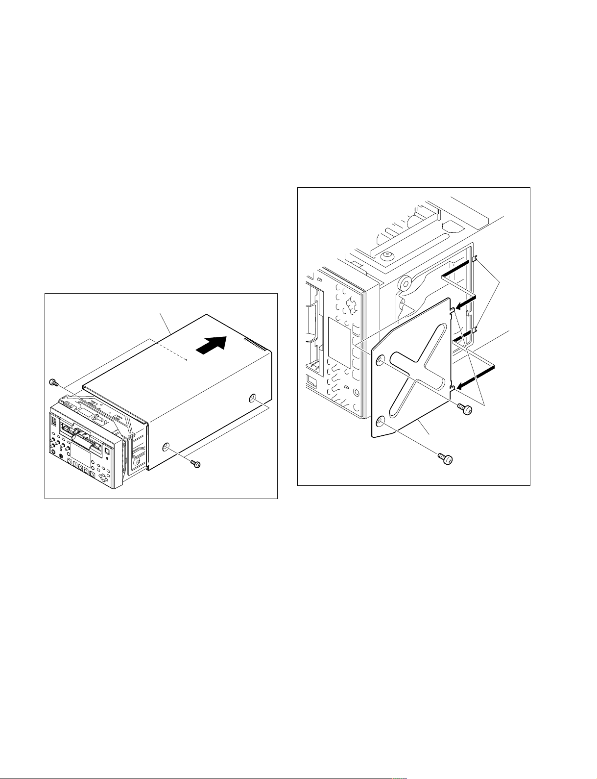
2-7-1. Removal/Installation of the Top Panel
1. Remove the four screws and remove the top panel in
the direction of the arrow.
n
Be careful not to break or peel off the internal packing.
2. Re-attach the parts in reverse order of the disassembling procedure.
Top panel
2-7-2. Removal/Installation of the Bottom
Plate
1. Stand the main unit on the left side.
2. Remove the two screws and remove the bottom plate
in the direction of the arrow.
3. Re-attach the parts in reverse order of the disassembling procedure.
Holes
B4 x 6
B4 x 6
Claws
BVTT3 x 6
Bottom plate
BVTT3 x 6
2-10
HVR-1500
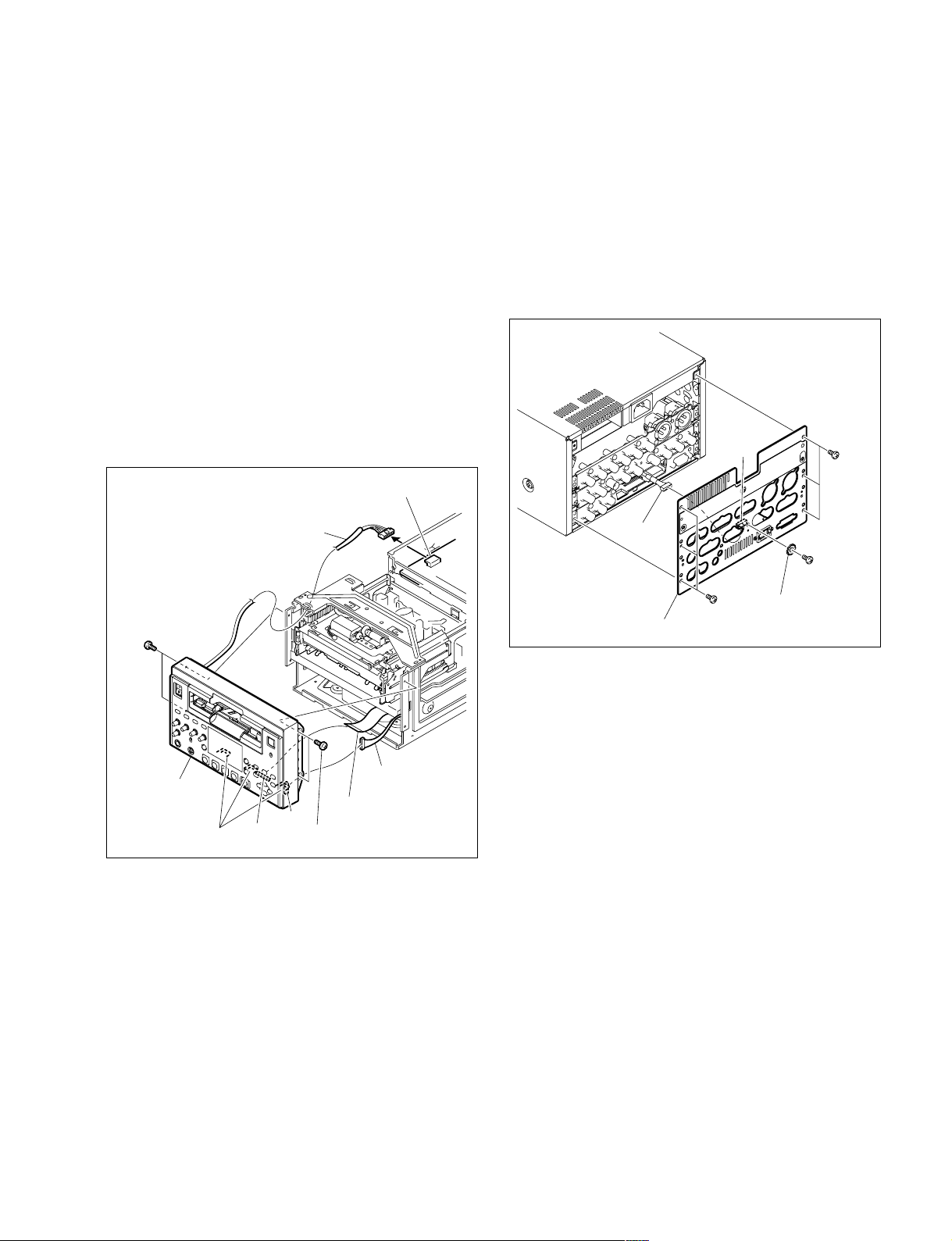
2-7-3. Removal/Installation of the Front
Panel
1. Remove the top panel. (Refer to Section 2-7-1.)
2. Remove the bottom plate.
(Refer to Section 2-7-2.)
3. Remove the harness (AC PSW) from the
connector (CN2) on the switching regulator.
4. Remove the flexible card wire from the connector (CN500) on the KY-616 board.
5. Remove the harness (KY-MB) from the connector (CN101) on the KY-614 board.
6. Remove the four screws.
7. Pull the front panel to the front to remove it.
8. Re-attach the parts in reverse order of the
disassembling procedure.
CN2
2-7-4. Removal/Installation of the Rear Panel
1. Remove the screw (B3 x 5) and toothed washer.
2. Remove the six screws (BV3 x 6) , and remove the
rear panel.
3. Remove the harness from the connector (CN2) on the
CN-1968A board.
4. Re-attach the parts in reverse order of the disassembling procedure.
CN2
BV3 x 6
BVTT3 x 6
Front panel
Harness (AC PSW)
CN500
Claws
CN101
BVTT3 x 6
Harness (KY-MB)
Flexible card wire
Harness
Rear panel
BV3 x 6
B3 x 5
Toothed washer
HVR-1500
2-11
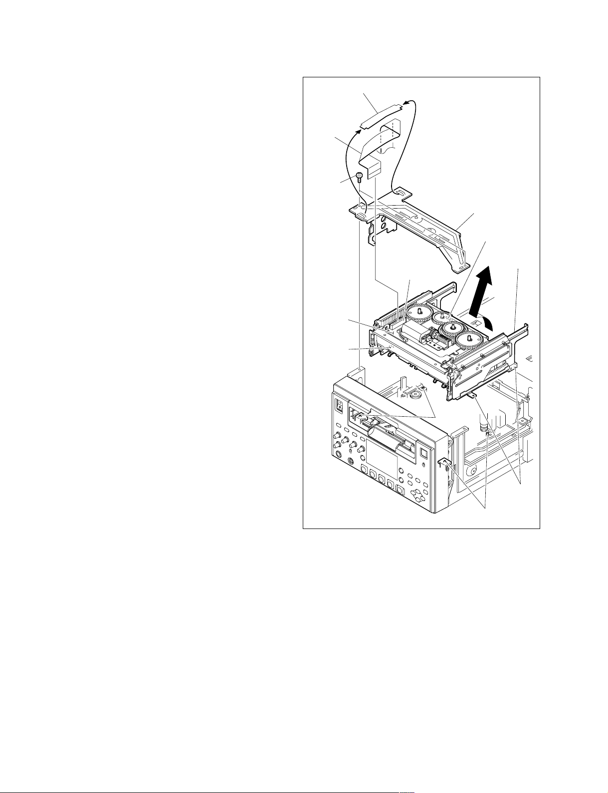
2-8. Removing/Installing the Cassette
Compartment
C cable retainer
Removal
1. Remove the top panel. (Refer to Section 2-7-1.)
2. Remove the C cable retainer.
3. Remove the flexible card wire from the connector
(CN1) on the CC-83G board.
4. Remove the two screws and remove the cassette
compartment retainer.
5. Remove the cassette compartment n the direction of
the arrow.
Installation
1. Put in the cassette compartment in the opposite
direction of the arrow and align the four positioning
holes with the four positioning pins.
2. Attach the cassette compartment with the two screws.
3. Connect the flexible card wire to the connector (CN1)
on the CC-83G board.
4. Attach the C cable retainer.
5. Attach the top panel. (Refer to Section 2-7-1.)
Flexible
card wire
BVTT3 x 6
Cassette compartment
retainer
Positioning hole
Cassette
compartment
CN1
CC-83G
board
Positioning
hole
Positioning
pins
Positioning pins
Positioning
holes
2-12
HVR-1500
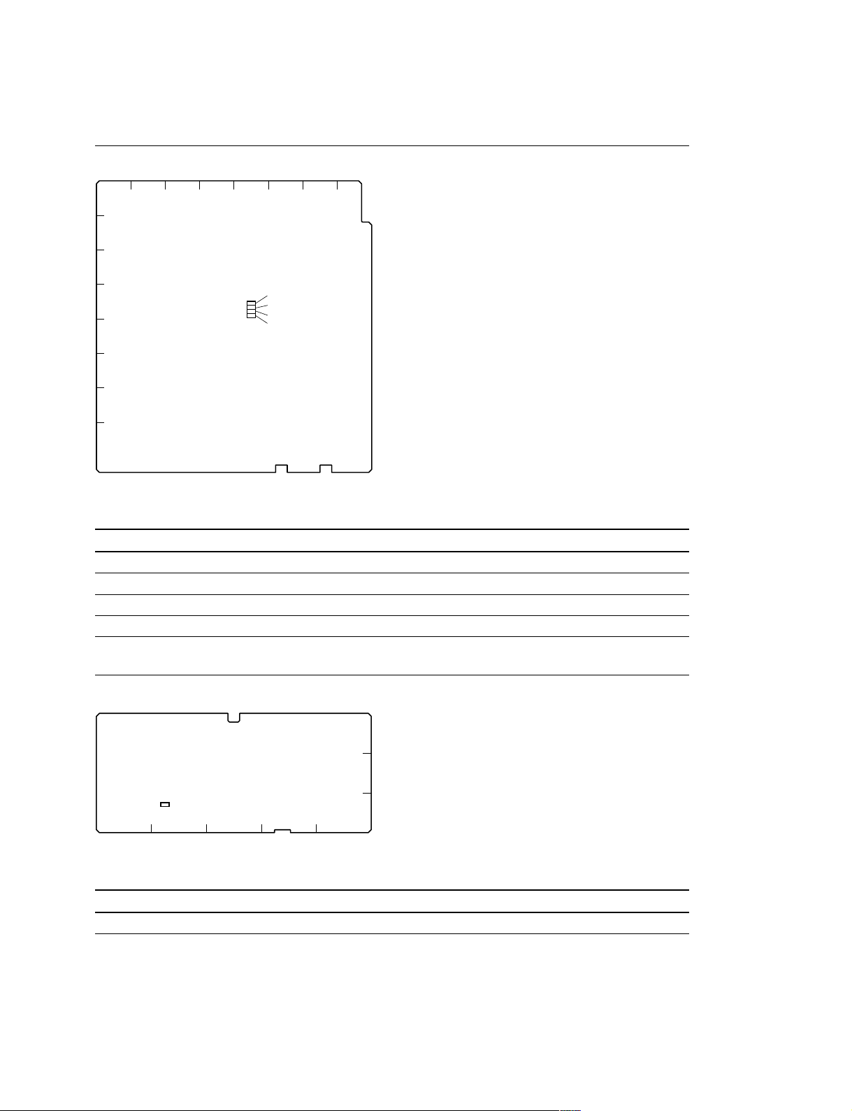
2-9. Function of Indicators on Circuit Boards
DDE-22 Board
1234567
A
B
C
D
E
F
G
H
D203
D202
D201
D200
8
A side (component side)
Ref. No. Name Color Description Normal state
D200 NON INTER Green Blinks in case of non-interlace signal. OFF
D201 NON STD Green Blinks, except for a standard signal. OFF
D202 VCXO SC LOCK Red Lights in case of standard signal OFF
D203 VCXO H LOCK Red Off in case of standard signal Lights
SDI-94 Board
3
2
D201
B
A side (component side)
Ref. No. Name Color Description Normal state
D201 UNLOCK Red Lights when SDI output signal is unlock. OFF
HVR-1500
1
AEDC
2-13
2-10. Switch Setting on Circuit Boards
n
Do not change the setting of switches when the “Factory use” is shown in the description.
HPR-20 Board
6543
21
A
S401
C
D
B
A side (component side)
Ref. No. Name Description Factory setting
S401 — Factory use ALL OFF
SSS-12 Board
5
4
3
S500
S401
2
1
ABCDE
A side (component side)
Ref. No. Name Description Factory setting
S401 — Factory use ALL OFF
S500 RESET Push this switch when resetting the system control. —
2-14
HVR-1500

2-11. Circuit Protection Parts (Fuse/IC
Link)
Circuit Protection Element
This unit is equipped with the positive characteristics
thermister(s) (power thermister) as the circuit protection
element. The positive characteristics thermister limits the
electric current flowing through the circuit as the internal
resistance increases when an exces-sive current flows or
when the ambient temperature increases.
If the positive characteristics thermister works, turn off the
main power of the unit and inspect the internal circuit of
this unit. After the cause of the fault is removed, turn on
the main power again. The unit works normally.
It takes about one minute to cool down the positive
characteristics thermister after the main power is turned off.
Board Ref. No. (Address) Part No.
CN-1968A THP1 (A-1/Side A) ! 1-805-726-11
THP2 (A-1/ Side A) ! 1-805-726-11
THP3 (A-1/ Side A) ! 1-805-726-11
THP4 (A-1/ Side A) ! 1-805-726-11
Fuse/IC Link
w
The fuse and IC link are essential parts for safe operation.
Replace the components with Sony parts whose part
numbers appear in the manual published by Sony. If the
components are replaced with any parts other than the
specified ones, this may cause a fire or electric shock.
This unit is equipped with Fuse(s) and IC link(s).
An excessive current flows due to abnormality inside the
equipment, the fuse and/or IC link blow. If they blow, turn
off the main power of the equipment, inspect inside of the
equipment, and remove the cause of excessive current.
After that, replace the fuse and/or IC link.
Board Ref. No. (Address) Part No./Name
AVP-7 F51 (D-8/Side A) ! 1-533-804-21
Fuse 2.5 A, 125 V
PS51 (C-8/Side A) ! 1-533-282-21
IC link 2 A, 72 V
PS52 (C-8/Side A) ! 1-533-282-21
IC link 2 A, 72 V
PS53 (C-8/Side A) ! 1-533-282-21
IC link 2 A, 72 V
PS54 (C-8/Side A) ! 1-533-282-21
IC link 2 A, 72 V
PS55 (E-9/Side A) ! 1-533-282-21
IC link 2 A, 72 V
Board Ref. No. (Address) Part No./Name
DDE-22 PS300 (A-4/Side A) ! 1-576-282-21
IC link 1.2 A, 72 V
PS301 (A-4/Side A) ! 1-576-282-21
IC link 1.2 A, 72 V
PS302 (A-5/Side A) ! 1-576-282-21
IC link 1.2 A, 72 V
PS303 (A-2/Side A) ! 1-576-282-21
IC link 1.2 A, 72 V
DR-428BG PS1 (E-2/Side A) ! 1-576-123-21
IC link 0.8 A, 72 V
PS2 (E-2/Side A) ! 1-576-123-21
IC link 0.8 A, 72 V
PS3 (F-2/Side A) ! 1-576-123-21
IC link 0.8 A, 72 V
PS4 (E-2/Side A) ! 1-576-123-21
IC link 0.8 A, 72 V
DVP-42 PS1301 (A-3/Side B) ! 1-576-677-21
IC link 4 A, 72 V
PS1302 (A-3/Side B) ! 1-533-282-21
IC link 2 A, 72 V
PS1303 (A-3/Side B) ! 1-533-282-21
IC link 2 A, 72 V
PS1304 (A-4/Side B) ! 1-533-282-21
IC link 2 A, 72 V
KY-614 PS100 (E-3/Side B) ! 1-576-282-21
IC link 1.2 A, 72 V
PS101 (E-3/Side B) ! 1-576-282-21
IC link 1.2 A, 72 V
PS102 (E-3/Side B) ! 1-576-282-21
IC link 1.2 A, 72 V
PS103 (E-3/Side A) ! 1-576-282-21
IC link 1.2 A, 72 V
PS104 (E-3/Side A) ! 1-576-282-21
IC link 1.2 A, 72 V
RP-133 PS101 (B-3/Side A) ! 1-576-282-21
IC link 1.2 A, 72 V
PS102 (B-3/Side A) ! 1-576-282-21
IC link 1.2 A, 72 V
PS103 (B-3/Side A) ! 1-576-282-21
IC link 1.2 A, 72 V
SSS-12 PS102 (C-5/Side A) ! 1-576-282-21
IC link 1.2 A, 72 V
PS103 (C-5/Side A) ! 1-576-282-21
IC link 1.2 A, 72 V
PS104 (C-5/Side A) ! 1-576-282-21
IC link 1.2 A, 72 V
PS105 (C-5/Side A) ! 1-576-282-21
IC link 1.2 A, 72 V
HVR-1500
2-15

2-12. Replacing NV-RAM and Memory Backup Battery
(1) Overview
This unit is provided with a batter backed RAM and EEPROMs on the boards.
These memory devices store system setup data, adjustment data, and other data.
When any of these devices or the backup battery is replaced, the memory data must be rewritten.
Board Ref. No. Type Stored data
AVP-7 IC156 EEPROM AVP BOARD ADJ adjustment value of maintenance menu
DR-428BG IC8 EEPROM Hours meter data
KY-616 IC300 EEPROM LCD ADJ adjustment value of maintenance menu
RP-133 IC501 EEPROM RP adjustment value of maintenance menu
SSS-12 IC538 RAM SYSTEM SEL setting data of setup menu
(with backup battery) Input/output setting data
IC539 EEPROM Setup menu data
Serial number data
Error log data
Mechanical deck adjustment value
Menu bank 1-3 data
2-16
HVR-1500
 Loading...