

Sony HT-DDW665 User Manual

4-252-086-82(1)
Home Theatre
System
Operating Instructions
Owner’s Record
The model and serial numbers are located on the rear of the unit. Record the serial
number in the space provided below. Refer to them whenever you call upon your
Sony dealer regarding this product.
Model No.
Serial No.
HT-DDW665
©2004 Sony Corporation
WARNING
To prevent fire or shock hazard, do not
expose the unit to rain or moisture.
To prevent fire, do not cover the ventilation of the
apparatus with newspapers, table-cloths, curtains, etc.
And don’t place lighted candles on the apparatus.
To prevent fire or shock hazard, do not place objects
filled with liquids, such as vases, on the apparatus.
Do not install the appliance in a confined space,
such as a bookcase or built-in cabinet.
Don’t throw away batteries with
general house waste; dispose of
them correctly as chemical waste.
This symbol is intended to alert
the user to the presence of
uninsulated “dangerous voltage”
within the product’s enclosure
that may be of sufficient
magnitude to constitute a risk of
electric shock to persons.
This symbol is intended to alert
the user to the presence of
important operating and
maintenance (servicing)
instructions in the literature
accompanying the appliance.
WARNING
This equipment has been tested and found to comply
with the limits for a Class B digital device, pursuant to
Part 15 of the FCC Rules. These limits are designed to
provide reasonable protection against harmful
interference in a residential installation. This
equipment generates, uses, and can radiate radio
frequency energy and, if not installed and used in
accordance with the instructions, may cause harmful
interference to radio communications. However, there
is no guarantee that interference will not occur in a
particular installation. If this equipment does cause
harmful interference to radio or television reception,
which can be determined by turning the equipment off
and on, the user is encouraged to try to correct the
interference by one or more of the following measures:
– Reorient or relocate the receiving antenna.
– Increase the separation between the equipment and
receiver.
– Connect the equipment into an outlet on a circuit
different from that to which the receiver is
connected.
– Consult the dealer or an experienced radio/TV
technician for help.
CAUTION
You are cautioned that any changes or modification not
expressly approved in this manual could void your
authority to operate this equipment.
Note to CATV system installer:
This reminder is provided to call CATV system
installer’s attention to Article 820-40 of the NEC that
provides guidelines for proper grounding and, in
particular, specifies that the cable ground shall be
connected to the grounding system of the building, as
close to the point of cable entry as practical.
NERGY STAR
E
mark. As an E
®
is a U.S. registered
NERGY STAR
®
partner,
Sony Corporation has determined that
this product meets the E
®
TAR
guidelines for energy
S
NERGY
efficiency.
US
2

About This Manual
• The instructions in this manual are for model
HT-DDW665. Check your model number by looking
at the lower right corner of the front panel.
• The instructions in this manual describe the controls
on the receiver. You can also use the controls on the
supplied remote if they have the same or similar
names as those on the receiver. For details on the use
of your remote, see pages 25–27.
The HT-DDW665 consists of:
• Receiver STR-K665P
• Speaker system
– Front speaker (left) SS-MSP66L
– Front speaker (right) SS-MSP66R
– Center speaker SS-CNP66
– Surround speaker (left) SS-MSP66SL
– Surround speaker (right) SS-MSP66SR
– Sub woofer SS-WMSP66
This receiver incorporates Dolby* Digital and Pro
Logic Surround and the DTS** Digital Surround
System.
* Manufactured under license from Dolby
Laboratories.
“Dolby”, “Pro Logic” and the double-D symbol are
trademarks of Dolby Laboratories.
** “DTS” and “DTS Digital Surround” are registered
trademarks of Digital Theater Systems, Inc.
Note for the supplied remote
For RM-U665
The >10/11 button on the remote is not
available.
US
3

Table of Contents
Getting Started
1: Connecting your components ............. 5
2: Connecting the antennas .....................7
3: Connecting speakers ...........................8
4: Connecting the AC power cord ........10
5: Setting up the speakers ..................... 11
6: Adjusting the speaker levels and
balance............................................12
— TEST TONE
Amplifier Operation
Selecting the component .......................13
Listening to FM/AM radio....................13
Presetting radio stations ........................ 14
Changing the display.............................15
About the indications in the display......16
Enjoying Surround Sound
Using only the front speakers and sub
woofer............................................. 17
— 2CH STEREO
Enjoying higher fidelity sound..............17
— AUTO FORMAT DIRECT
Selecting a sound field ..........................18
Advanced Adjustments and
Settings
Switching the audio input mode for digital
components..................................... 20
— INPUT MODE
Customizing sound fields......................20
Adjusting the tone................................. 22
Advanced settings................................. 22
Other Operations
Naming preset stations and inputs........ 24
Operations Using the Remote
RM-U665
Before you use your remote.................. 25
Remote button description.................... 25
Additional Information
Precautions ........................................... 28
Troubleshooting.................................... 29
Specifications ....................................... 31
List of button locations and reference
pages............................................... 33
Index ..................................................... 34
US
4
Getting Started
1: Connecting your components
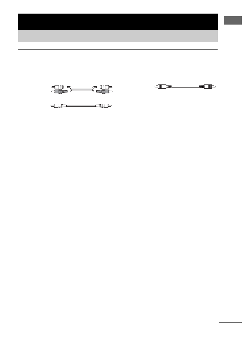
Required cords
The hookup diagram on page 6 assume the use of the following optional connection cords (A to C)
(not supplied unless indicated).
A Audio cord
White (L)
Red (R)
B Coaxial digital cord (supplied)
Orange
Notes
• Turn off the power to all components before making any connections.
• Be sure to make connections firmly to avoid hum and noise.
• When connecting an audio cord, be sure to match the color-coded pins to the appropriate jacks on the components:
white (left, audio) to white; and red (right, audio) to red.
• When connecting optical digital cords, insert the cord plugs straight in until they click into place.
• Do not bend or tie optical digital cords.
C Optical digital cord
Getting Started
continued
US
5
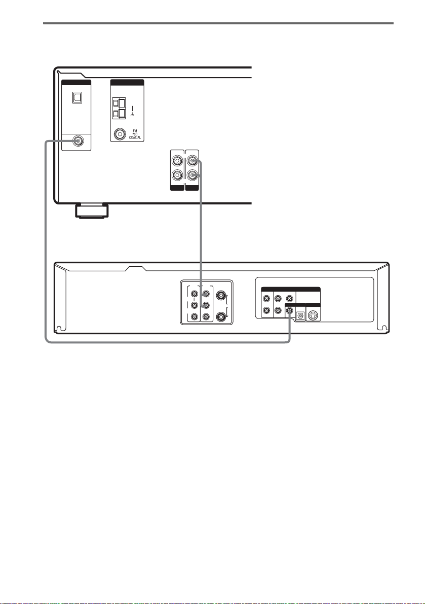
Hooking up your DVD player and VCR
For details on the required cords (A–C), see page 5.
DIGITAL
OPTICAL
VIDEO
IN
B
DVD IN
COAXIAL
ANTENNA
AM
L
R
AUDIO IN AUDIO IN
VIDEO
DVD
A
LINE
LINE
IN
IN 1
OUT
AUDIO
VIDEO
(FROM ANT.)
R
L
OUT
(TO TV)
RF
LINE OUT
AUDIO
DVD Only
COMPONENT VIDEO OUT
L
Pb
R
COAXIAL
YPr
OPTICAL
S-VIDEO OUTDIGITAL AUDIO OUT
Note
If you connect other components, use the remote and operating instructions supplied with the connected components
for operation.
US
6
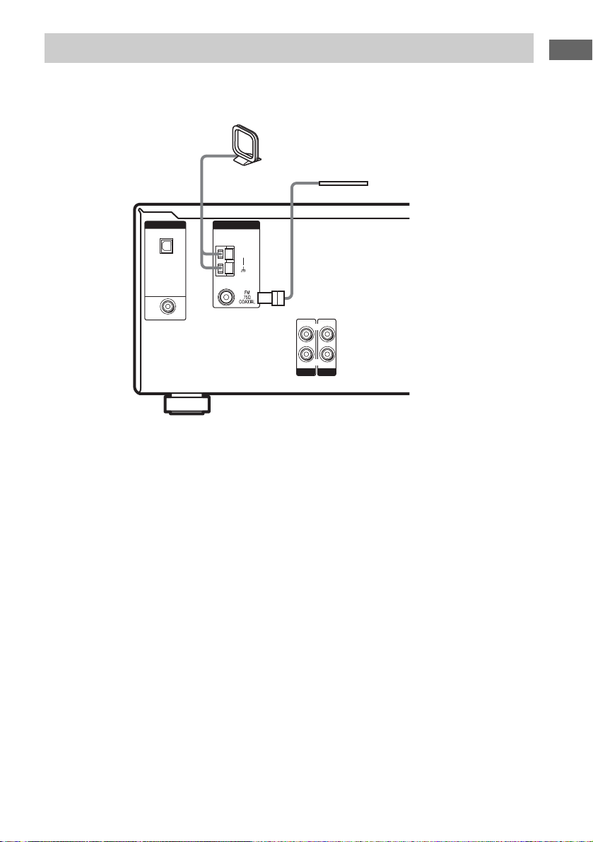
2: Connecting the antennas
Connect the supplied AM loop antenna and FM wire antenna.
AM loop antenna
(supplied)
FM wire antenna
(supplied)
Getting Started
DIGITAL
OPTICAL
VIDEO
IN
DVD IN
COAXIAL
ANTENNA
AM
L
R
AUDIO IN AUDIO IN
VIDEO
DVD
Notes
• To prevent noise pickup, keep the AM loop antenna away from the receiver and other components.
• Be sure to fully extend the FM wire antenna.
• After connecting the FM wire antenna, keep it as horizontal as possible.
US
7
3: Connecting speakers
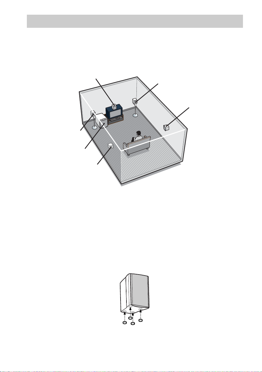
Connect your speakers to the receiver. This receiver allows you to use a 5.1 channel speaker system.
To fully enjoy theater-like multi channel surround sound requires five speakers (two front speakers, a
center speaker, and two surround speakers) and a sub woofer (5.1 channel).
Example of 5.1 channel speaker system configuration
Center speaker
Front speaker (Right)
Surround speaker (Right)
Front speaker (Left)
Sub woofer
Surround speaker (Left)
Tips
• Since the sub woofer does not emit highly directional signals, you can place it wherever you want.
• For greater flexibility in the positioning of the speakers, use the optional WS-FV11 or WS-FV10D floor stand
(available only in certain countries).
Note
Connect the long speaker connecting cords to the surround speaker terminals and the short speaker connecting cords
to the front and center speaker terminals.
Attaching foot pads
To prevent speaker vibration or movement, attach the supplied foot pads to the speaker as shown in the
illustration below.
Note
Be sure to attach the supplied foot pads to the sub woofer as well.
US
8
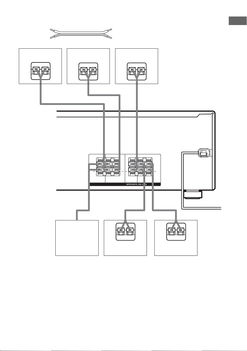
Required cord
A Speaker cords (supplied)
(+)
(–)
Getting Started
Surround speaker
(Right)
Ee
A
Surround speaker
(Left)
Ee
A
+ +
SUB
WOOFER
Center speaker
RL
RL
SURROUND
SPEAKERS
Ee
A
RL
+ +
RL
CENTER
FRONT
A
E
Sub woofer Front speaker
Front speaker
(Right)
eAE
(Left)
e
US
9
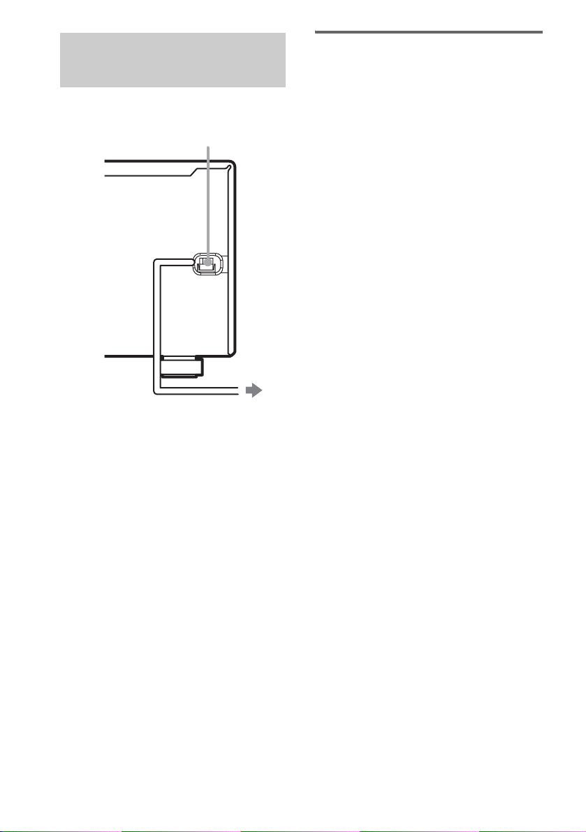
4: Connecting the AC power cord
Connect the AC power cord to a wall outlet.
AC power cord
To a wall outlet
Performing initial setup
operations
Before using the receiver for the first time,
initialize the receiver by performing the
following procedure.
This procedure can also be used to return
settings you have made to their factory defaults.
Use the buttons on the receiver for the operation.
1 Press ?/1 to turn off the receiver.
2 Hold down ?/1 for 5 seconds.
“PUSH” and “ENTER” appears in the
display alternatingly.
3 Press ENTER.
“ CLEARING” appears in the display for a
while, then “CLEARED” appears.
The following are reset to their factory
settings.
• All settings in the SET UP, LEVEL,
TONE and CUSTOMIZE menus.
• The sound field memorized for each
input and preset station.
• All sound field parameters.
• All preset stations.
• All index names for inputs and preset
stations.
• MASTER VOLUME –/+ is set to “VOL
MIN”.
10
US
5: Setting up the speakers
You can use the SET UP menu to set the
distance and location of the speakers connected
to this receiver.
1 Press ?/1 to turn on the receiver.
2 Press MAIN MENU repeatedly to select
“ SET UP ”.
3 Press or repeatedly to select the
parameter you want to adjust.
For details, see “Speaker setup parameters”
below.
Note
Some speaker setup items may appear dimmed in
the display. This means that they have been
adjusted automatically due to other speaker
settings or may not be adjustable.
4 Press + or – repeatedly to select the
setting you want.
The setting is entered automatically.
5 Repeat steps 3 and 4 until you have set
all of the items that follow.
Speaker setup parameters
The initial setting is underlined.
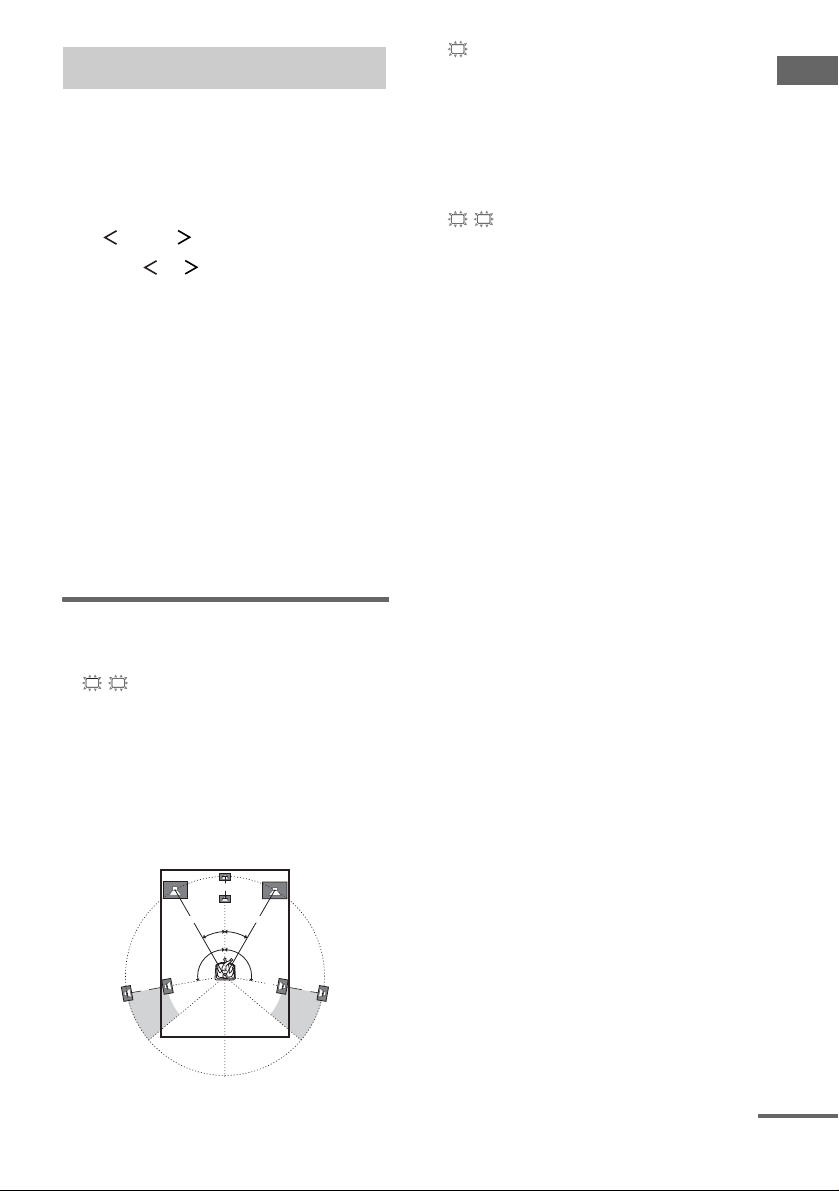
L
R
x DIST. XX ft.
(Front speaker distance)
Initial setting: 10 ft.
Lets you set the distance from your listening position
to the front speakers (A). You can adjust from 3 to 23
feet in 1 foot steps.
If both front speakers are not placed an equal distance
from your listening position, set the distance to the
closest speaker.
B
A
A
30˚30˚
100˚-120˚100˚-120˚
C
x DIST. XX ft.
(Center speaker distance)
Initial setting: 10 ft.
Lets you set the distance from your listening position
to the center speaker. Center speaker distance should
be set from a distance equal to the front speaker
distance (A) to a distance 5 feet closer to your
listening position (B).
SR
SL
x DIST. XX ft.
(Surround speaker distance)
Initial setting: 10 ft.
Lets you set the distance from your listening position
to the surround speakers. Surround speaker distance
should be set from a distance equal to the front speaker
distance (A) to a distance 15 feet closer to your
listening position (C).
If both surround speakers are not placed an equal
distance from your listening position, set the distance
to the closest speaker.
Tip
The receiver lets you to input the speaker position in
terms of distance. However, it is not possible to set the
center speaker further than the front speakers. Also, the
center speaker cannot be set more than 5 feet closer
than the front speakers.
Likewise, the surround speakers cannot be set further
away from the listening position than the front
speakers. And they can be no more than 15 feet closer.
This is because incorrect speaker placement is not
conducive to the enjoyment of surround sound.
Please note that, setting the speaker distance closer than
the actual location of the speakers will cause a delay in
the output of the sound from that speaker. In other
words, the speaker will sound like it is further away.
For example, setting the center speaker distance 3–6
feet closer than the actual speaker position will create
a fairly realistic sensation of being “inside” the screen.
If you cannot obtain a satisfactory surround effect
because the surround speakers are too close, setting the
surround speaker distance closer (shorter) than the
actual distance will create a larger sound stage.
Adjusting these parameter while listening to the sound
often results in much better surround sound. Give it a
try!
Getting Started
CC
continued
11
US
 Loading...