

Sony HDW-F900H User Manual

HD CAMCORDER
HDW-F900
HDW-F900H
MAINTENANCE MANUAL Part 1
2nd Edition (Revised 1)
Serial No. 12001 and Higher

! WARNING
This manual is intended for qualified service personnel only.
To reduce the risk of electric shock, fire or injury, do not perform any servicing other than that
contained in the operating instructions unless you are qualified to do so. Refer all servicing to
qualified service personnel.
! WARNUNG
Die Anleitung ist nur für qualifiziertes Fachpersonal bestimmt.
Alle Wartungsarbeiten dürfen nur von qualifiziertem Fachpersonal ausgeführt werden. Um die
Gefahr eines elektrischen Schlages, Feuergefahr und Verletzungen zu vermeiden, sind bei
Wartungsarbeiten strikt die Angaben in der Anleitung zu befolgen. Andere als die angegeben
Wartungsarbeiten dürfen nur von Personen ausgeführt werden, die eine spezielle Befähigung
dazu besitzen.
! AVERTISSEMENT
Ce manual est destiné uniquement aux personnes compétentes en charge de l’entretien. Afin
de réduire les risques de décharge électrique, d’incendie ou de blessure n’effectuer que les
réparations indiquées dans le mode d’emploi à moins d’être qualifié pour en effectuer d’autres.
Pour toute réparation faire appel à une personne compétente uniquement.
X-RAY RADIATION WARNING
Be sure that parts replacement in the high voltage block
and adjustments made to the high voltage circuits are
carried out precisely in accordance with the procedures
given in this manual.
HDW-F900 P1E2

CAUTION
ADVARSEL
Danger of explosion if battery is incorrectly replaced.
Replace only with the same or equivalent type
recommended by the manufacturer.
Dispose of used batteries according to the
manufacturer’s instructions.
Vorsicht!
Explosionsgefahr bei unsachgemäßem Austausch
der Batterie.
Ersatz nur durch denselben oder einen vom
Hersteller empfohlenen ähnlichen Typ. Entsorgung
gebrauchter Batterien nach Angaben des
Herstellers.
ATTENTION
Il y a danger d’explosion s’il y a remplacement
incorrect de la batterie.
Remplacer uniquement avec une batterie du même
type ou d’un type équivalent recommandé par le
constructeur.
Mettre au rebut les batteries usagées conformément
aux instructions du fabricant.
Lithiumbatteri - Eksplosjonsfare.
Ved utskifting benyttes kun batteri som
anbefalt av apparatfabrikanten.
Brukt batteri returneres
apparatleverandøren.
VARNING
Explosionsfara vid felaktigt batteribyte.
Använd samma batterityp eller en likvärdig typ
som rekommenderas av apparattillverkaren.
Kassera använt batteri enligt gällande
föreskrifter.
VAROITUS
Paristo voi räjähtää jos se on virheellisesti
asennettu.
Vaihda paristo ainoastaan laitevalmistajan
suosittelemaan tyyppiin.
Hävitä käytetty paristo valmistajan ohjeiden
mukaisesti.
Levér det brugte batteri tilbage til leverandøren.
HDW-F900 P1E2
ADVARSEL!
Lithiumbatteri-Eksplosionsfare ved fejlagtig
håndtering.
Udskiftning må kun ske med batteri
af samme fabrikat og type.
1 (P)

For the customers in the Netherlands
Voor de klanten in Nederland
Hoe u de batterijen moet verwijderen, leest u in de tekst
van deze handleiding deel 2.
Gooi de batterij niet weg maar lever deze in als klein
chemisch afval (KCA).
Für Kunden in Deutschland
Entsorgungshinweis: Bitte werfen Sie nur entladene
Batterien in die Sammelboxen beim Handel oder den
Kommunen. Entladen sind Batterien in der Regel dann,
wenn das Gerät abschaltet und signalisiert “Batterie
leer” oder nach längerer Gebrauchsdauer der Batterien
“nicht mehr einwandfrei funktioniert”. Um
sicherzugehen, kleben Sie die Batteriepole z.B. mit
einem Klebestreifen ab oder geben Sie die Batterien
einzeln in einen Plastikbeutel.
For the customers in the U.S.A. and Canada
RECYCLING LITHIUM-ION BATTERIES
Lithium-Ion batteries are recyclable.
You can help preserve our environment
by returning your used rechargeable
batteries to the collection and recycling
location nearest you.
For more information regarding recycling of rechargeable batteries, call toll free
1-800-822-8837, or visit http://www.rbrc.org/
Caution: Do not handle damaged or leaking Lithium-Ion
batteries.
2 (P)
HDW-F900 P1E2

Table of Contents
Manual Structure
Purpose of this manual .............................................................................................. 5
Related manuals......................................................................................................... 5
Contents ..................................................................................................................... 6
1. Installation
1-1. Checking the ROM and Software Version..................................................1-1
1-2. Supplied Accessories ..................................................................................1-1
1-3. Operating Conditions ..................................................................................1-1
1-4. Connectors...................................................................................................1-1
1-5. Input/Output Signals ...................................................................................1-2
2. Service Overview
2-1. Removal and Installation of Exterior Parts ................................................. 2-1
2-2. Main Parts Location and Circuit Configuration.......................................... 2-2
2-2-1. PC Board Location .....................................................................2-2
2-2-2. Location of Main Mechanical Parts ........................................... 2-5
2-2-3. Location/Functions of Sensors ...................................................2-6
2-3. Settings of Board Switches and Short-circuit Pins .....................................2-8
2-3-1. APR-55 Board ............................................................................2-8
2-3-2. HN-243 Board ..........................................................................2-10
2-3-3. IF-819 Board ............................................................................ 2-11
2-3-4. RP-113 Board........................................................................... 2-11
2-3-5. SV-218 Board...........................................................................2-12
2-3-6. SY-285 Board...........................................................................2-12
2-4. How to Clean the Head When the Head is Clogged ................................. 2-12
2-5. Plug-in Board Removal and Installation ...................................................2-13
2-5-1. General Information of Plug-in Board Removal
and Installation .........................................................................2-13
2-5-2. AD-171 Board ..........................................................................2-14
2-5-3. DPR-227 Board ........................................................................2-14
2-5-4. IF-819, SV-218, SY-285 Boards..............................................2-15
2-6. Cassette Compartment Assembly Removal and Installation .................... 2-16
2-7. Cassette Tape Manual Ejection .................................................................2-18
2-8. Fixtures and Measuring Equipment for Adjustment.................................2-19
2-8-1. Fixtures.....................................................................................2-19
2-8-2. Measuring Equipment .............................................................. 2-21
HDW-F900 P1E2
1

3. Error Code and Error Message
3-1. Error Code................................................................................................... 3-1
3-2. Error Message .............................................................................................3-2
3-3. DIAGNOSTIC Mode ..................................................................................3-3
4. Setup Menu
4-1. Setup Menu .................................................................................................4-1
4-2. TOP Menu................................................................................................... 4-3
4-3. USER Menu ................................................................................................ 4-4
4-4. USER MENU CUSTOMIZE Menu............................................................4-4
4-5. OPERATION Menu.................................................................................... 4-5
4-6. PAINT Menu.............................................................................................4-13
4-7. MAINTENANCE Menu ........................................................................... 4-26
4-8. FILE Menu ................................................................................................4-33
4-9. DIAGNOSIS Menu................................................................................... 4-39
5. File System
5-1. File Structure............................................................................................... 5-1
5-2. Operator File ...............................................................................................5-2
5-3. Preset Operator File.....................................................................................5-3
5-4. Registering the Scene File...........................................................................5-4
5-5. Registering Reference Files ........................................................................5-6
5-6. Registering the Lens File ............................................................................5-9
5-7. Registering the OHB File.......................................................................... 5-10
5-7-1. Storing the Black Shading and White Shading ........................ 5-10
5-7-2. Adjusting the ND Offset ..........................................................5-11
5-8. File items................................................................................................... 5-12
2
HDW-F900 P1E2

6. Periodic Maintenance and Inspection
6-1. Cleaning ......................................................................................................6-1
6-1-1. General Information on Cleaning...............................................6-1
6-1-2. Cleaning of Tape Running Surface of Upper Drum
and Video Heads ........................................................................6-3
6-1-3. Cleaning of Tape Running Surface of Lower Drum
and Lead Surface........................................................................ 6-4
6-1-4. Cleaning of Stationary Heads and Cleaning Blade .................... 6-5
6-1-5. Cleaning of Tape Path System ................................................... 6-6
6-1-6. Cleaning of Filter .......................................................................6-7
6-2. Maintenance After Use in Special Environments ....................................... 6-8
6-3. Periodic Inspections ....................................................................................6-9
6-3-1. Hours Meter ...............................................................................6-9
6-3-2. Periodic Inspection List............................................................6-10
6-3-3. Recommended Replacing Parts................................................6-12
7. Overall Block Diagrams
7-1. Camera Block.............................................................................................. 7-1
7-2. VTR Block .................................................................................................. 7-4
HDW-F900 P1E2
3


Purpose of this manual
Related manuals
Manual Structure
This manual is the maintenance manual part 1 of HD Camcorder HDW-F900 and
HDW-F900H.
This manual is intended for use by trained system and service engineers, and is
provided information required for the installation, maintenance information and
information for primary service.
HDW-F900H is all the same as HDW-F900, except that the HD Electronic Viewfinder HDVF-20A is not supplied with HDW-F900H.
Besides this maintenance manual part 1, the following manuals are available.
..
. HDW-F900, HDW-F900H Operation Manual (Supplied with this unit)
..
This manual is necessary for the use and the operation of this unit.
Part No. : 3-203-941-XX
..
. HDW-F900 Maintenance Manual Part 2 Volume 1, Volume 2
..
(Available on your request)
This manual is provided information that is premised the parts level service
(adjustments, board layouts, schematic diagrams, detailed parts lists and the like.)
for this unit.
If this manual is required, please contact to your local Sony Sales Office/Service
Center.
Volume 1 (Service Information , Replacement of Parts and Adjustments)
Part No. : 9-968-563-XX
Volume 2 (Schematic Diagrams, Board Layouts, Block Diagrams, Exploded
Views and Parts Lists).
Part No. : 9-968-564-XX
HDW-F900 P1E2
..
. HDVF-20A Operation Manual (Supplied with HDVF-20A)
..
This manual is necessary for the use and the operation of HDVF-20A.
Part No. : 3-203-934-XX
..
. HDVF-20A Maintenance Manual (Available on your request)
..
This manual is provided information that is premised the parts level service
(adjustments, board layouts, schematic diagrams, detailed parts lists and the like.)
for HDVF-20A.
If this manual is required, please contact to your local Sony Sales Office/Service
Center.
Part No. : 9-968-559-XX
..
. HDVF-C30W Operation Manual (Supplied with HDVF-C30W)
..
This manual is necessary for the use and the operation of HDVF-C30W.
Part No. : 3-775-745-XX
5

Contents
..
. HDVF-C30W Maintenance Manual (Available on your request)
..
This manual is provided information that is premised the parts level service
(replacement of the parts, board layouts, schematic diagrams, detailed parts lists
and the like.) for HDVF-C30W.
If this manual is required, please contact to your local Sony Sales Office/Service
Center.
Part No. : 9-968-009-XX
The maintenance manual part 1 is organized by following sections.
Section 1 Installation
This section is described about the information that is required to install (operating
conditions, connection information and the like.) and when installing this unit.
Section 2 Service Overview
This section is described about fundamental information that is required for service
(removing of cabinet and cassette compartment, location of printed circuit boards
and main parts, fixture and measuring equipments, and the like.), measures against
trouble.
Section 3 Error Code and Error Message
This section is described about DIAGNOSTIC mode, error messages and error code.
Section 4 Setup Menu
This section is described about the setup menu.
Section 5 File System
This section is described about the file system to control data.
Section 6 Periodic Maintenance and Inspection
This section is described about the recommended periodic maintenance and the
cleaning procedures.
Section 7 Overall Block Diagrams
This section is described about overall block diagrams.
6
HDW-F900 P1E2

Section 1
Installation
1-1. Checking the ROM and Software
Version
When connecting the following peripheral equipment to
the unit, confirm that the versions of the ROMs and
software which are installed in each model. If the version
is lower than the following one, the ROM needs to be
replaced and the software needs to be upgraded.
In this case, contact your local Sony Sales Office/Service
Center.
ROM
Peripheral Board name Ref No. ROM version
equipment
MSU-700A CPU-293 IC5, IC6 Ver. 1.10 or higher
MSU-750 CPU-286 IC5, IC6 Ver. 1.10 or higher
RCP-720/721 MPU-79 IC10 Ver. 2.73 or higher
RCP-730/731 MPU-79 IC10 Ver. 2.73 or higher
RCP-740/741 MPU-79 IC10 Ver. 2.73 or higher
RCP-700/701 MPU-92 IC6 Ver. 2.73 or higher
RM-B150 CPU-266 IC4 Ver. 1.00 or higher
Software
Peripheral Board name Software version
equipment
RCP-750/751 MPU-123 Ver. 1.01 or higher
RM-B750 MPU-124 Ver. 1.00 or higher
1-2. Supplied Accessories
1-3. Operating Conditions
Operating temperature : 0 dC to 40 dC
Storage temperature : _20 dC to +60 dC
Humidity : No condensation allowed
Locations to avoid :
. Extremely hot or cold places
. Very humid places
. Places with strong vibrations
. Places with strong electric or magnetic fields
. Places exposed to direct sunlight for a long time or near
heaters
1-4. Connectors
When connecting cables to the connectors during installation or maintenance work, use the following connectors or
cables.
Connector name Connection connectors/Cables
GENLOCK IN (RETURN)
TC IN 1-560-069-11
TC OUT BNC Coaxial Connector
MONITOR OUT Y Plug
MONITOR OUT Pb
MONITOR OUT Pr
AUDIO IN CH1/CH2 1-508-084-00 XLR 3-pin, Male
AUDIO OUT 1-508-370-00 XLR 5-pin, Female
MIC IN +48 V 1-508-084-00 XLR 3-pin, Male
DC IN 1-508-362-00 XLR 4-pin, Female
DC OUT 12 V 1-566-425-11 Round Type 4-pin, Male
REMOTE 1-766-848-11 Round Type 8-pin, Male
Accessories Sony Part No. Qt’y
Michrophone 1-542-295-1X 1
Spacer, Michrophone 3-179-882-0X 1
Holder (B), Michrophone 3-680-582-0X 1
Cover, Rain 3-725-262-0X 1
Belt Assy, Shoulder A-6772-374-X 1
Operation Manual — 1
Maintenance Manual Part 1 — 1
HDW-F900 P1E2
1-1

1-5. Input/Output Signals
1-5. Input/Output Signals
Input
GENLOCK IN (RETURN) : 1.0 V p-p, 75 Z
TC IN : 0.5 V to 18 V p-p, 10 kZ
Output
MONITOR OUT : 1.0 V p-p, 75 Z, unbalanced
TC OUT : 1.0 V p-p, 75 Z
EARPHONE : 8 Z, _∞ to_18 dBu variable
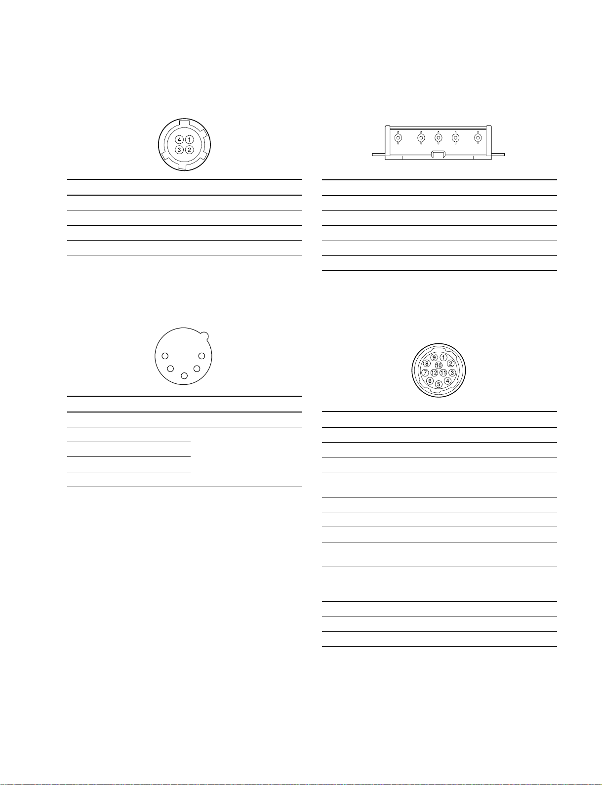
DC IN : XLR, 4-pin (Male)
<External View>
14
23
No. Signal I/O Specifications
1 GND — GND for BATT OUT (+)
2 — No connection
3 — No connection
4 BATT OUT (+)IN+11 to 17 V dc
MIC IN +48 V : XLR, 3-pin (Female)
<External View>
12
3
No. Signal I/O Specifications
1 CAM MIC (G) — _ 60 dBu
2 CAM MIC (X) IN High impedance, Balanced
3 CAM MIC (Y) IN
(0 dBu = 0.775 V rms)
AUDIO IN CH-1, CH-2 : XLR, 3-pin (Female)
<External View>
12
3
No. Signal I/O Specifications
1 MIC/LINE (G) — _60 dBu/+4 dBu, selectable
2 MIC/LINE (X) IN High impedance, Balanced
3 MIC/LINE (Y) IN
(0 dBu = 0.775 V rms)
1-2
HDW-F900 P1E2
1-5. Input/Output Signals
DC OUT 12 V : DIN, 4-pin(Female)
<External View>
No. Signal I/O Specifications
1 UNREG GND — GND for POWER
2 — No connection
3 — No connection
4 UNREG +12 V OUT +11 to 17 V dc
AUDIO OUT : XLR, 5-pin (male)
<External View>
1
5
2
4
3
BATT IN : 5-pin (Male)
<External View>
12345
No. Signal I/O Specifications
1 BATT IN (_)
2 BATT ID
3 BATT REM
4 LIGHT CONT
5 BATT IN (+)IN+11 to 17 V dc
LENS : 12-pin (Female)
<External View>
No. Signal I/O Specifications
1 ANALOG GND —
2 AUDIO_PB (X) OUT 0 dBm (600 Z terminated)
3 AUDIO_PB (Y) OUT
4 AUDIO_PB_SUB (X) OUT
3 AUDIO_PB_SUB (Y) OUT
(0 dBu = 0.775 V rms)
No. Signal I/O Specifications
1 RET (SW) IN ON : 0 V, OFF : OPEN
2 VTR TRIG IN ON : 0 V, OFF : OPEN
3 LENS GND —
4 AUTO +5 V IN AUTO : +5 V,
MANU : 0 V or OPEN
5 IRIS CONT OUT +3.4 V (F16) to +6.2 V (F2.8)
6 UNREG +12 V OUT +11 V to 17 V
7 IRIS PSTN IN +3.4 V (F16) to +6.2 V (F2.8)
8 REMOTE/LOCAL OUT AUTO IRIS : 0 V
MANUAL IRIS : +5 V
9 EXTENDER IN EX 2 ON : 0 V
EX 0.8 ON : +1.8 V
OFF : +4.8 V
10 ZOOM PSTN IN WIDE : 2 V, TELE : 7 V
11 LENS RX
12 LENS TX
HDW-F900 P1E2
1-3
1-5. Input/Output Signals
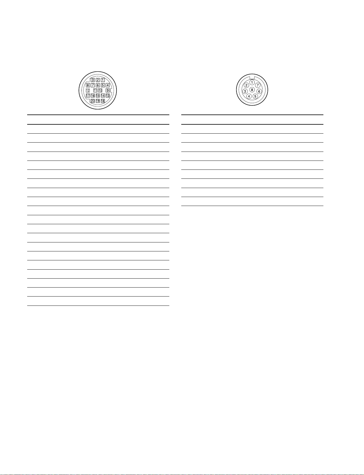
VF : 20-pin (Female)
<External View>
No. Signal I/O Specifications
1 SDA VF I/O TTL level
2 — No connection
3 — No connection
4 SCL VF OUT TTL level
5 COLOR/BW IN ON : Color, OFF : B/W
6 — No connection
7 — No connection
8 G TALLY OUT ON : 5 V, OFF : GND
9 VF PEAKING CTL OUT 1.0 V p-p, Zo = 75 Z
10 — No connection
11 — No connection
12 VF VIDEO (Y) OUT 1.0 V p-p, Z0 = 75 Z
13 VF VIDEO GND — GND for VIDEO
14 VF VIDEO (Pb) OUT ±0.35 V p-p, Zo = 75 Z
15 VF VIDEO (Pr) OUT ±0.35 V p-p, Zo = 75 Z
16 — No connection
17 R TALLY (UP) OUT ON : 5 V, OFF : GND
18 — No connection
19 VF GND — GND for VF
20 UNREG +12 V OUT +11 V to 17 V
REMOTE : 8-pin (Female)
<External View>
No. Signal I/O Specifications
1 TX RCP DATA (X) OUT SERIAL DATA OUT
2 TX RCP DATA (Y) OUT SERIAL DATA OUT
3 RX RCP DATA (X) IN SERIAL DATA IN
4 RX RCP DATA (Y) IN SERIAL DATA IN
5 TX GND — GND for TX
6 UNREG +12 V OUT + 11 V to 17 V
7 UNREG (GND) — GND for UNREG
8 Y OUT 1.0 V p-p, Zo = 75 Z
CHASSIS GND — CHASSIS GND
1-4
HDW-F900 P1E2
Section 2
Service Overview
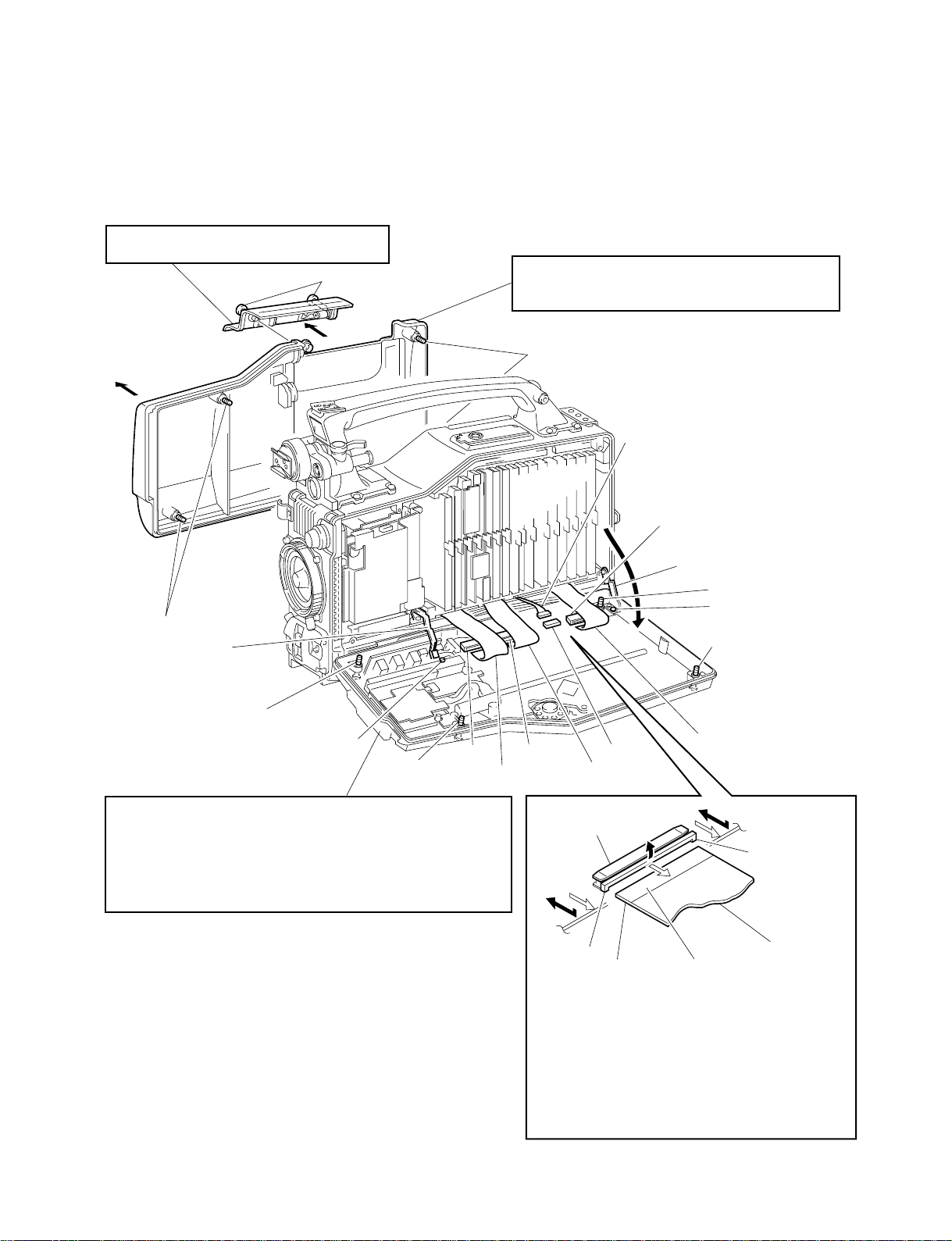
2-1. Removal and Installation of Exterior Parts
Front Lid
Loosen the two screws fully and remove the front lid.
(Stoppers are provided for these screws.)
Screws with stopper
Outside Panel
1. Remove the front lid.
2. Loosen the four screws fully and remove the outside panel.
(Stoppers are provided for these screws.)
Screws with stopper
Harness (MB-APR)
CN140
Screws with stopper
Strap
Screw with stopper
PWH2.6 x 5
Screw
Inside Panel
Loosen the four screws fully and turn the inside panel in the arrow direction.
1.
(Stoppers are provided for these screws.)
2.
Disconnect the three flexible card wires from the connectors
(CN140, 141, 142).
Disconnect the harness (MB-APR) from the connector (CN10).
3.
Remove the strap screw (PWH2.6 x 5).
4.
5.
Remove the joining link screw (PWH2.6 x 5).
with stopper
CN141 CN142 CN10
Flexible
card wire
Joining link
Screw with stopper
PWH2.6 x 5
Screw with stopper
Flexible card wire
Flexible card wire
Connector
A
*
*
Conductor side
How to disconnect
Slide the two sections marked * of the connector in the
direction of the arrow (white), and disconnect the flexible
card wire.
Blue (Insulator side)
Flexible card wire
HDW-F900 P1E2
How to connect
1.)
Lift the two sections marked * of the connector in the
direction of arrow A, and insert the flexible card wire fully.
2.)
Push in the two sections marked * of the connector in the
direction of the arrow (black).
2-1
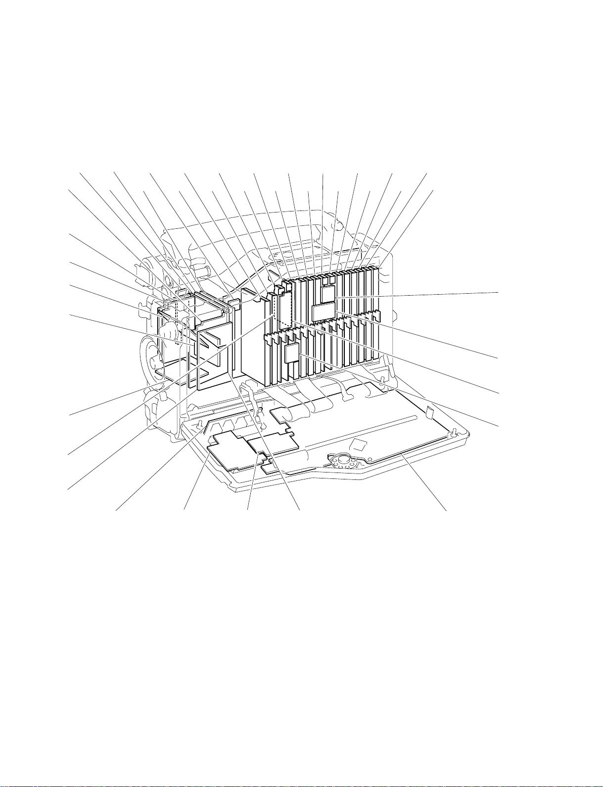
2-2. Main Parts Location and Circuit Configuration
2-2. Main Parts Location and Circuit Configuration
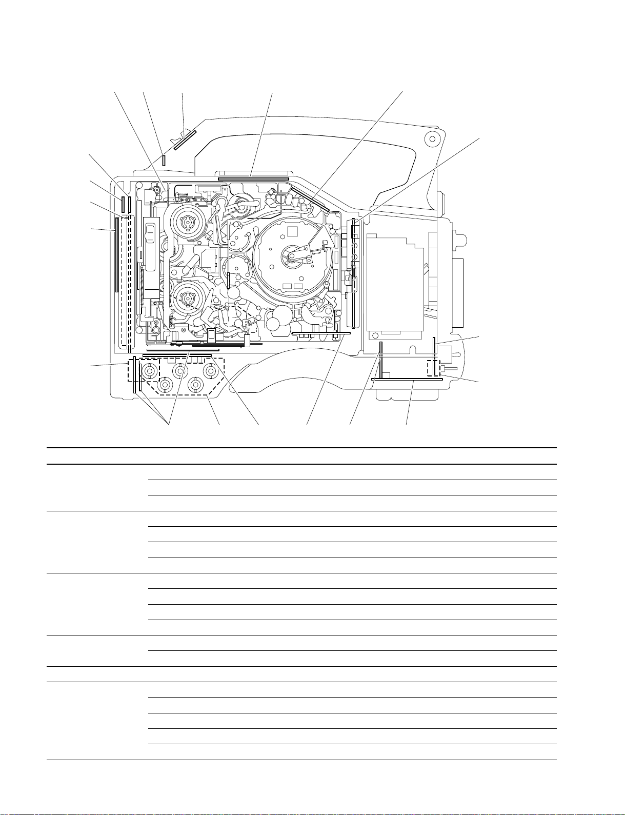
2-2-1. PC Board Location
#,
#'
#;
#\
#]
#[
#.
1
3456789
$/ 2 0!-!=![!]!\!;!'!,!.@/
@-
@=
@[
@]
#=
#-
#/
@.
@,
@'
@\
2-2
HDW-F900 P1E2

2-2. Main Parts Location and Circuit Configuration
System Configuration Board Name Circuit Function No.
CCD unit BI-145 (B) CCD block #\
BI-145 (G) CCD block #]
BI-145 (R) CCD block #[
CN-2119/CN-1432 CCD block 3
CN-1946 CCD block @'
DR-411 CCD driver, Timing generator #,
DU-68/DU-19 Connector Board #.
NR-75 CCD block #'
PA-238 Pre-amp #;
RP-113 CCD block 1
SH-74 Shading correction signal generator 2
TG-213 Timing generator $/
Camera AD-171 Flare, PRE knee, White clip, Black clip, PRE filter, A/D converter 7
CN-1614 Filter #-
CN-1940 Relay board for AD-171 board and DPR-227 board @[
CN-2085 Relay board for DPR-227 board and DA-148 board @]
DA-148 Post filter, D/A converter 9
DPR-227 SCVP (Digital processing), VFS (Frame rate converter) 8
DPR-157 Digital processing #=
IF-819 System controller, Fan controller !=
RE-145F Power supply, Regulator (CCD block) 5
SG-267 GEN lock, Timing pulse generator (CTG), Character generator !VA-195 Video amp, White gain, White shading compensator 6
VDA-51 Monitor out, VF out, Character mix, Marker mix, Zebra mix, Skin marker mix !/
Video DEC-95 ECC/BRR decoder !,, !.
EN-143 BRR encoder (B), Timing generator !;
ENC-59 BRR encoder (A), ECC encoder !\
EQ-89 RF equalizer @/
VN-12 Concealment, FIL (Rate convert) !'
Servo SV-218 Servo controller ![
System control SY-285 System controller for VTR block, Timecode controller !]
Time code, Audio APR-55 Audio processor @\
Others CN-2043 Connector board for Memory Stick @.
CN-2044 Relay board for IF-819 board and SY-285 board @=
CN-2078 Relay board for SV-218 board and SY-285 board @-
CP-361 Control panel #/
MB-877 Mother board 4
VR-175 Memory card, Audio select switch, Alarm level, Monitor level @,
HDW-F900 P1E2
2-3
2-2. Main Parts Location and Circuit Configuration
12 3 4 5
!.
!,
!'
!;
6
7
!\
8
90!-!=![!]
System Configuration Board Name Circuit Function No.
Head CTL-10 CTL head amp 5
CUE-2 CUE head amp !HN-243 Harness, Erase head amp, TC head amp 6
Mic CN-1642 Connector board for Camera mic !/
MA-92 Camera mic amp 9
SW-911 VTR S/S switch, Shutter switch, ABB/AWB switch 7
SW-912 Rotary encoder switch 8
Connector box CN-2025 Connector board for Audio IN/OUT & EXT DC IN/OUT !]
CN-2046 Connector board for Monitor OUT, EXT TC IN/OUT 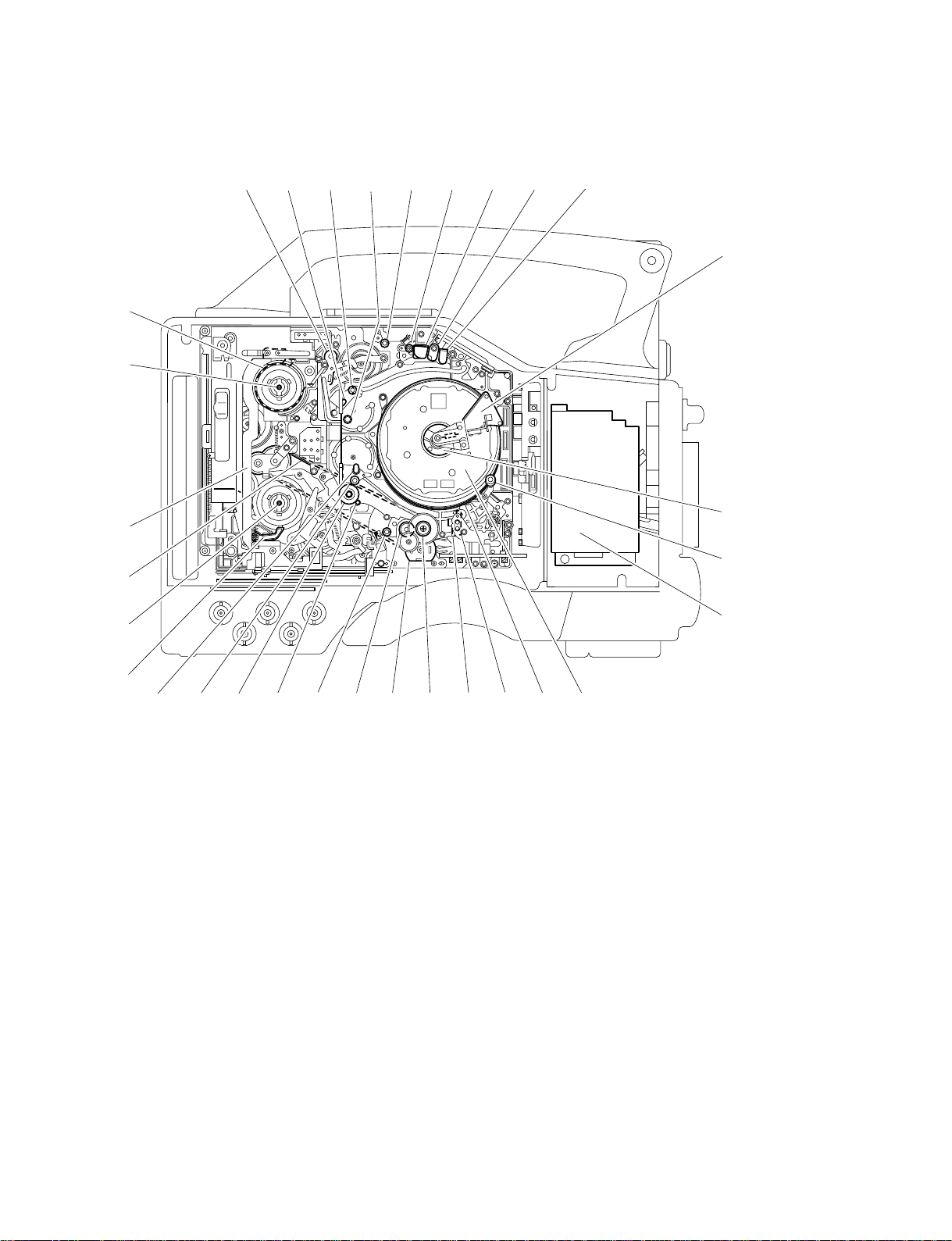
2-2-2. Location of Main Mechanical Parts
12345678 9
#-
#/
@.
2-2. Main Parts Location and Circuit Configuration
0
!-
@,
@'
@;
1 Tension regulator arm
2 S1 tape guide (on S slider )
3 S2 tape guide (on S slider )
4 Tension regulator guide ( S4 tape guide )
5 S5 tape guide
6 S3 tape guide
7 Full erase head
8 Tape cleaner
9 CTL head
!/ Brush
!- Slip ring
!= Video head cleaner
![ CCD block
!] Upper drum
!\ Lower drum
!; CUE head cleaner
!=
![
!]!\!;!'!,!.@/@-@=@[@]@\
!' CUE/TC head
!, Manual eject knob
!. Threading motor
@/ Capstan motor
@- T3 tape guide
@= T drawer guide
@[ Pinch roller
@] T2 tape guide (on T slider )
@\ T1 tape giude (on T slider )
@; T soft brake
@' T reel table
@, Timing belt
@. Gear
#/ S reel table
#- Brake band
HDW-F900 P1E2
2-5
2-2. Main Parts Location and Circuit Configuration
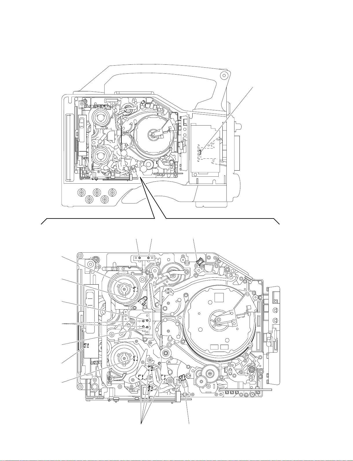
2-2-3. Location/Functions of Sensors
1
!=
!-
0
(SPARE)
9
8
7
23 4
2-6
65
HDW-F900 P1E2

11
1 Temperature Sensor
11
This sensor detects the temperature to perform black correction.
22
2 Cassette-in sensor
22
This sensor detects whether a cassett is in.
33
3 REC INHIBIT sensor
33
This sensor detects the REC inhibiting plug of the cassette tape.
44
4 Tape end sensor
44
This sensor detects the end of the tape running in the forward direction.
55
5 Tape top sensor
55
This sensor detects the end of the tape running in the REW direction.
66
6 Function cam sensor
66
This sensor detects the rotation position of a cam.
77
7 Take-up reel table rotation sensor
77
This sensor detects the rotation of the take-up reel table. The FG output signal
of this sensor is fed to a servo circuit so as to calculate the winding diameter of
the tape.
2-2. Main Parts Location and Circuit Configuration
88
8 Cassette lock sensor (switch)
88
This sensor detects whether the cassette compartment is locked.
99
9 Tape thickness sensor
99
Using a tub on the back side of the cassette tape, this sensor detects the thickness of the tape wound on a cassette tape that is being inserted into the unit.
!/!/
!/ Reel hub diameter sensor
!/!/
The reel hub diameter of a cassette tape varies depending on the length of the
tape wound on the cassette tape. The reel hub diameter sensor detects the reel
hub diameter by the tab on the back side of the cassette tape. The output signal
of this sensor is fed to a servo circuit so as to calculate the winding diameter of
the tape.
!-!-
!- Condensation sensor
!-!-
This sensor detects whether condensation occurs in the unit.
!=!=
!= Supply reel table rotating sensor
!=!=
This sensor detects the rotation of the supply reel table. The FG output signal of
this sensor is fed to a servo circuit so as to calculate the winding diameter of the
tape.
HDW-F900 P1E2
2-7
2-3. Settings of Board Switches and Short-circuit Pins
2-3. Settings of Board Switches and Short-circuit Pins
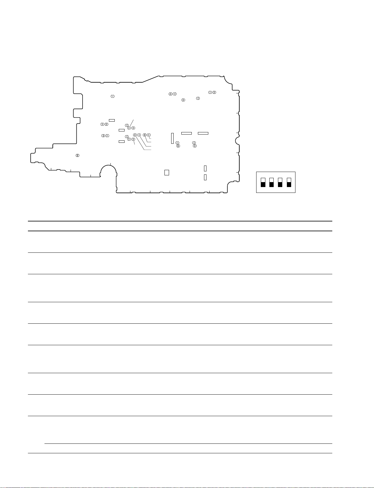
2-3-1. APR-55 Board
6
5
4
3
2
S540
1
K
ON
1234
SL104
SL110
SL109
SL105
SL106
S519
S520
JH
SL203
SL204
SL201
SL202
SL103
SL101
SL102
S103 S152
S101
SL108
SL107
S540
G
SL100
S400
SL403SL404
SL401SL402
SL400
A
B
D
C
S402
S10
SL406
SL405
SL408
SL410
SL409
SL407
FE
(Side B)
Switches on APR-55 Board
Switch No. Designation Description Factory setting
S10 CH-1 OUTPUT LIM CH-1 Selects whether to turn on or off the output limiter. ON
ON-OFF ON : Audio output LIMITER ON
OFF : Audio output LIMITER OFF
S402 CH-2 OUTPUT LIM CH-2 Selects whether to turn on or off the output limiter. ON
ON-OFF ON : Audio output LIMITER ON
OFF : Audio output LIMITER OFF
S101 CH-1 FRONT MIC VR Selects whether to adjust the REAR CH-1 audio input signal level by the OFF
ON-OFF FRONT MIC VR.
ON : Adjust
OFF : Not adjust
S103 CH-1 LIM ON-OFF Selects whether to turn on or off the limiter in the CH-1 audio input stage. OFF
ON : CH1 Audio INPUT LIMITER ON
OFF : CH1 Audio INPUT LIMITER OFF
S152 CH-2 LIM ON-OFF Selects whether to turn on or off the limiter in the CH-2 audio input stage. OFF
ON : CH2 Audio INPUT LIMITER ON
OFF : CH2 Audio INPUT LIMITER OFF
S400 CUE ON-OFF Selects whether to feed the CUE signal or D/A signal to the audio output OFF
terminal in the PB mode.
ON : Feed the CUE signal
OFF : Feed the D/A signal
S519 EXT-LK UBIT INT-EXT Selects whether to lock the user bit externally. INT
INT : Not lock externally
EXT : Lock externally
S520 REAL TIME VITC-LTC Select which user bit REAL TIME is recorded onto. VITC
VITC : U-BIT of VITC
LTC : U-BIT of LTC
S540 1 AUDIO SG MONITOR Selects whether to feed the 1 KHz test signal to MONITOR OUT when OFF
ON-OFF the signal is selected.
ON : Feed
OFF : Not feed
2 to 4 — Factory use ON or OFF
*1: The settings of S540-2 to 4 vary according to the version of the board. Therefore do not change the factory setting.
*1
2-8
HDW-F900 P1E2

Slit Lands on APR-55 Board
Ref. No. Name Input level
2-3. Settings of Board Switches and Short-circuit Pins
++
(
+4 dBu) 0 dBu
++
SL101 CH-1 AUDIO INPUT OPEN OPEN OPEN SHORT
SL102 LEVEL Select OPEN SHORT OPEN OPEN
SL103 OPEN OPEN SHORT OPEN
SL104 CH-2 AUDIO INPUT OPEN OPEN OPEN SHORT
SL105 LEVEL Select OPEN SHORT OPEN OPEN
SL106 OPEN OPEN SHORT OPEN
__
_1 dBu
__
__
_3 dBu
__
( ) : Factory setting
Ref. No. Name Headroom level
(20 dB) 18 dB 16 dB
SL107 REC CH-1 HEADROOM OPEN SHORT OPEN
SL108 LEVEL Select OPEN OPEN SHORT
SL109 REC CH-2 HEADROOM OPEN SHORT OPEN
SL110 LEVEL Select OPEN OPEN SHORT
SL201 REC CH-3 HEADROOM OPEN SHORT OPEN
SL202 LEVEL Select OPEN OPEN SHORT
SL203 REC CH-4 HEADROOM OPEN SHORT OPEN
SL204 LEVEL Select OPEN OPEN SHORT
SL401 PB CH-1 HEADROOM OPEN SHORT OPEN
SL402 LEVEL Select OPEN OPEN SHORT
SL403 PB CH-2 HEADROOM OPEN SHORT OPEN
SL404 LEVEL Select OPEN OPEN SHORT
( ) : Factory setting
Ref. No. Name Output level
++
+4 dBm (0 dBm)
++
SL405 CH-1 AUDIO OUTPUT OPEN OPEN SHORT
SL407 LEVEL Select SHORT OPEN OPEN
SL408 SHORT OPEN OPEN
SL406 CH-2 AUDIO OUTPUT OPEN OPEN SHORT
SL409 LEVEL Select SHORT OPEN OPEN
SL410 SHORT OPEN OPEN
Ref. No. Name Factory use
SL100 _ OPEN
SL400 _ SHORT
HDW-F900 P1E2
__
_3 dBm
__
( ) : Factory setting
2-9
2-3. Settings of Board Switches and Short-circuit Pins
2-3-2. HN-243 Board
1
S4
2
A
CN21
B
C
D
(Side A)
S1
1
RV1
2
D
C
B
A
S1
ON
12
(Side B)
Switches on HN-243 Board
Switch No. Designation Description Factory setting
S1 1 ADJ Turns on or off the adjustment mode. OFF
ON : The adjustment mode ON
OFF : The adjustment mode OFF
2 TRK Turns on or off the tracking control. OFF
ON : The tracking control volume (RV1) ON
OFF : The tracking control volume (RV1) OFF
S4 REC head PB selector switch Selects the normal REC or REC head PB. REC
REC : Normal REC
TEST : REC head PB
2-10
HDW-F900 P1E2
2-3-3. IF-819 Board
2-3. Settings of Board Switches and Short-circuit Pins
1
2
S300
S300
ON
E D C BA
(Side B)
1234
IF-819 Board Switch
Switch No. Designation Description Factory setting
S300 1 to 4 SETUP MENU Setup menu to be displayed on the OFF
Select viewfinder can be selected. (See the table below)
Switch Settings Setup Menu
S300-1 S300-2 S300-3 S300-4 USER USER MENU OPERATION PAINT MAINTENANCE FILE DIAGNOSIS
CUSTOMIZE
OFF OFF OFF OFF Yes Yes Yes Yes Yes Yes Yes
ON OFF OFF OFF Yes Yes Yes Yes Yes No Yes
OFF ON OFF OFF Yes Yes Yes Yes No No Yes
ON ON OFF OFF Yes Yes Yes No No No Yes
OFF OFF ON OFF Yes Yes Yes No No No No
2-3-4. RP-113 Board
All the switches on the RP-113 board are “Factory use”. Never change the settings.
(Factory setting : OFF)
HDW-F900 P1E2
2-11

1234
ON
S1
2-3. Settings of Board Switches and Short-circuit Pins
2-4. How to Clean the Head When the Head is Clogged
2-3-5. SV-218 Board
A B C D
CN9
1
2
(Side A)
SV-218 Board Switch
Switch No. Description Factory setting
S1 1to 4 Factory use OFF
2-3-6. SY-285 Board
A B C D
CN10
1
E
S1
E
S2
2
S2
ON
1234
(Side A)
SY-285 Board Switch
Switch No. Description Factory setting
S2 1 to 4 Factory use OFF
2-4. How to Clean the Head When the Head is Clogged
When the head is clogged, refer to Section 6, Periodic Maintenance and Inspection for appropriate headcleaning.
2-12
HDW-F900 P1E2
Screwdriver, etc.
Panel hole
Pull ring
2-5. Plug-in Board Removal and Installation
2-5. Plug-in Board Removal and
Installation
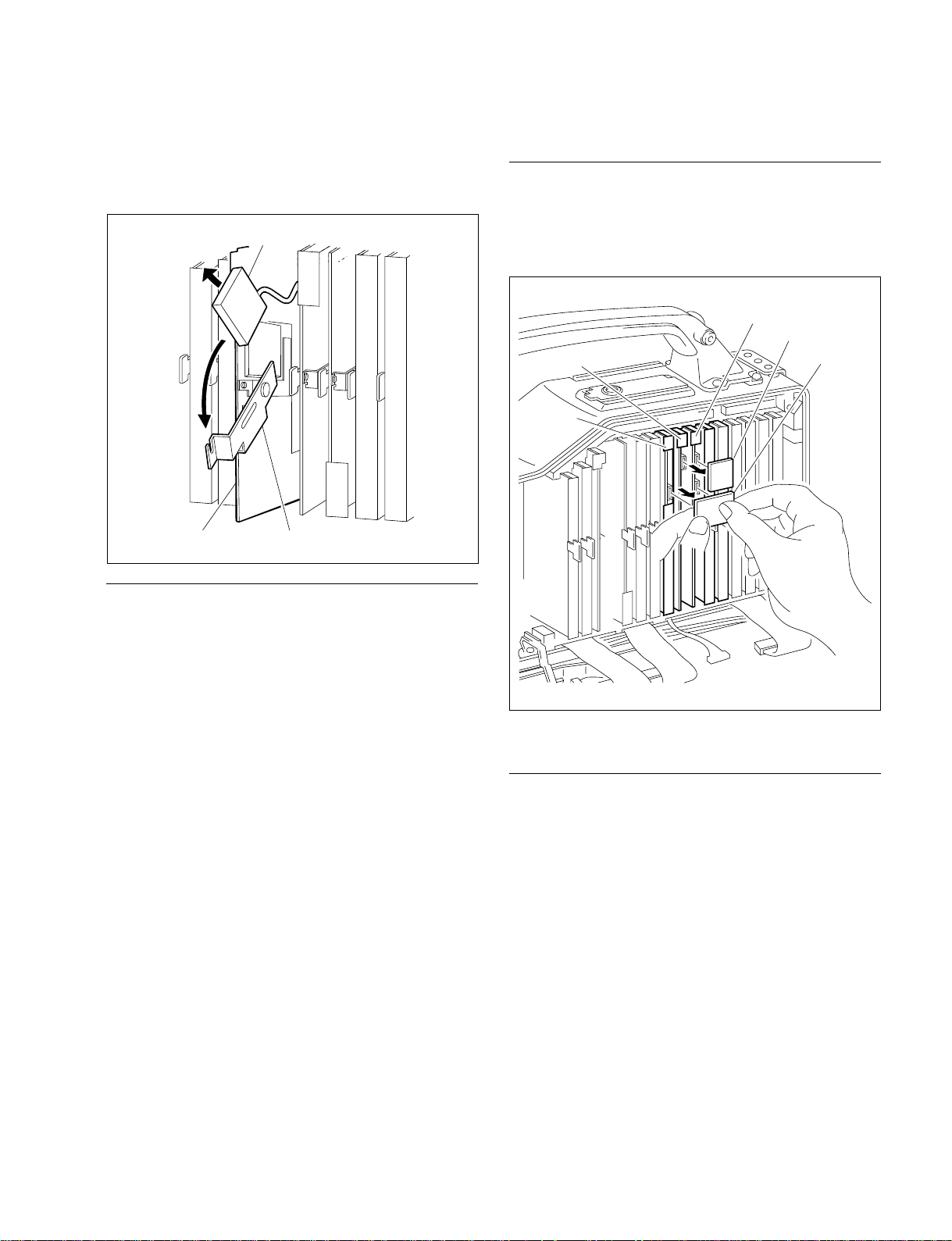
2-5-1. General Information of Plug-in Board
Removal and Installation
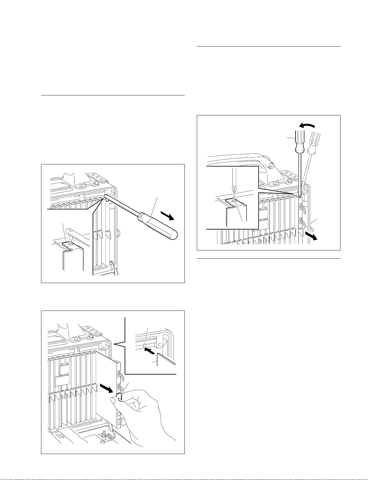
Removal with the Tool
Board removing tool (Sony Part No. : J-6309-350-A)
1. Insert the board removing tool in the hole on the panel
at the top of the board, move the tool in the direction
of the arrow, and disconnect the connector connected
to the mother board.
Board removing tool
Panel hole
Removal Without the Tool
1. Insert a screwdriver having a small tip into the panel
hole on the top of the board, move the tool in the
direction of the arrow, and disconnect the connector
connected to the mother board.
2. Holding the pull ring in front of the board, remove the
board from the unit
2. Remove the board from the unit by holding the pull
ring in front of the board.
. Installation
Groove of guide rail
Plug-in board
Pull ring
Installation
1. Insert the board according to the board guide rails at
the top and bottom of the unit.
2. Hold the top and bottom of the board firmly, and insert
the board connector into the mother board.
HDW-F900 P1E2
2-13
2-5. Plug-in Board Removal and Installation
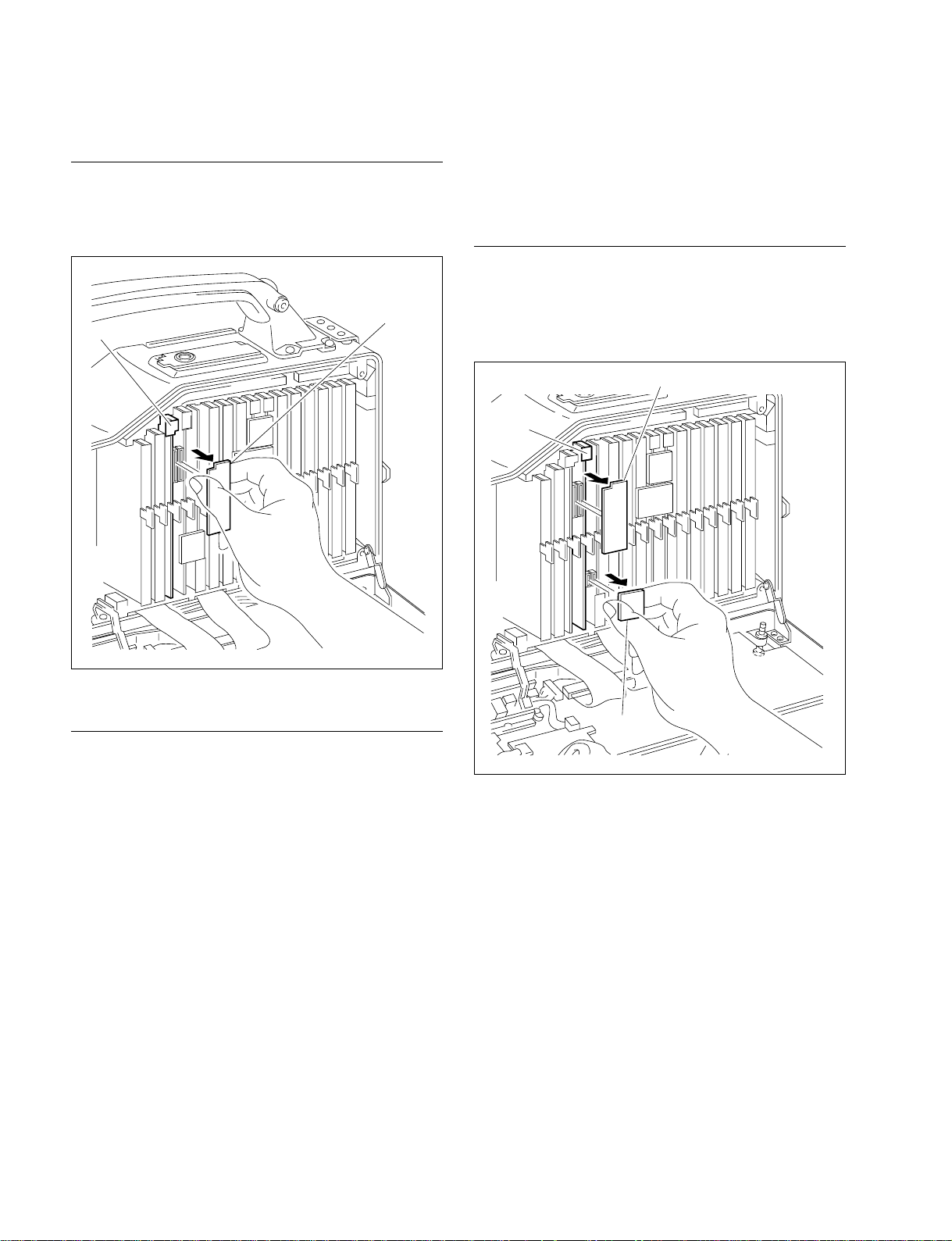
2-5-2. AD-171 Board
Removal
1. Open the inside panel. (Refer to Section 2-1.)
2. Draw out the CN-1940 board in the arrow direction.
CN-1940 board
AD-171 board
2-5-3. DPR-227 Board
n
Handle the flexible card wires carefully as they break
easily.
Removal
1. Open the inside panel. (Refer to Section 2-1.)
2. Draw out the CN-1940 and CN-2085 boards in the
arrow direction.
CN-1940 board
DPR-227
board
3. Draw out the AD-171 board.
Installation
Install in the reverse order of removal.
n
When installing the CN-1940 board, align the connector
position and insert it carefully and securely.
CN-2085
board
2-14
HDW-F900 P1E2
2-5. Plug-in Board Removal and Installation
3. Release the clamper retaining the heat pipe unit in the
arrow direction.
4. Draw carefully out the DPR-227 board while lifting up
the heat pipe unit.
Heat pipe unit
DPR-227 board
Clamper
2-5-4. IF-819, SV-218, SY-285 Boards
Removal
1. Open the inside panel. (Refer to Section 2-1.)
2. Draw out the CN-2044 and CN-2078 boards in the
arrow direction.
SY-285 board
CN-2078 board
SV-218 board
IF-819
board
CN-2044
board
Installation
1. Insert the DPR-227 board with the heat pipe unit lifted
up.
2. Reinstall the heat pipe unit, and install the clamper.
3. Align the connector position and insert the CN-1940
and CN-2085 boards carefully and securely.
4. Close the inside panel. (Refer to Section 2-1.)
3. Draw out the IF-819, SV-218 and SY-285 boards.
Installation
Install in the reverse order of removal.
n
When installing the relay boards (CN-2044 and CN-2078),
align the connector position and insert them carefully and
securely.
HDW-F900 P1E2
2-15
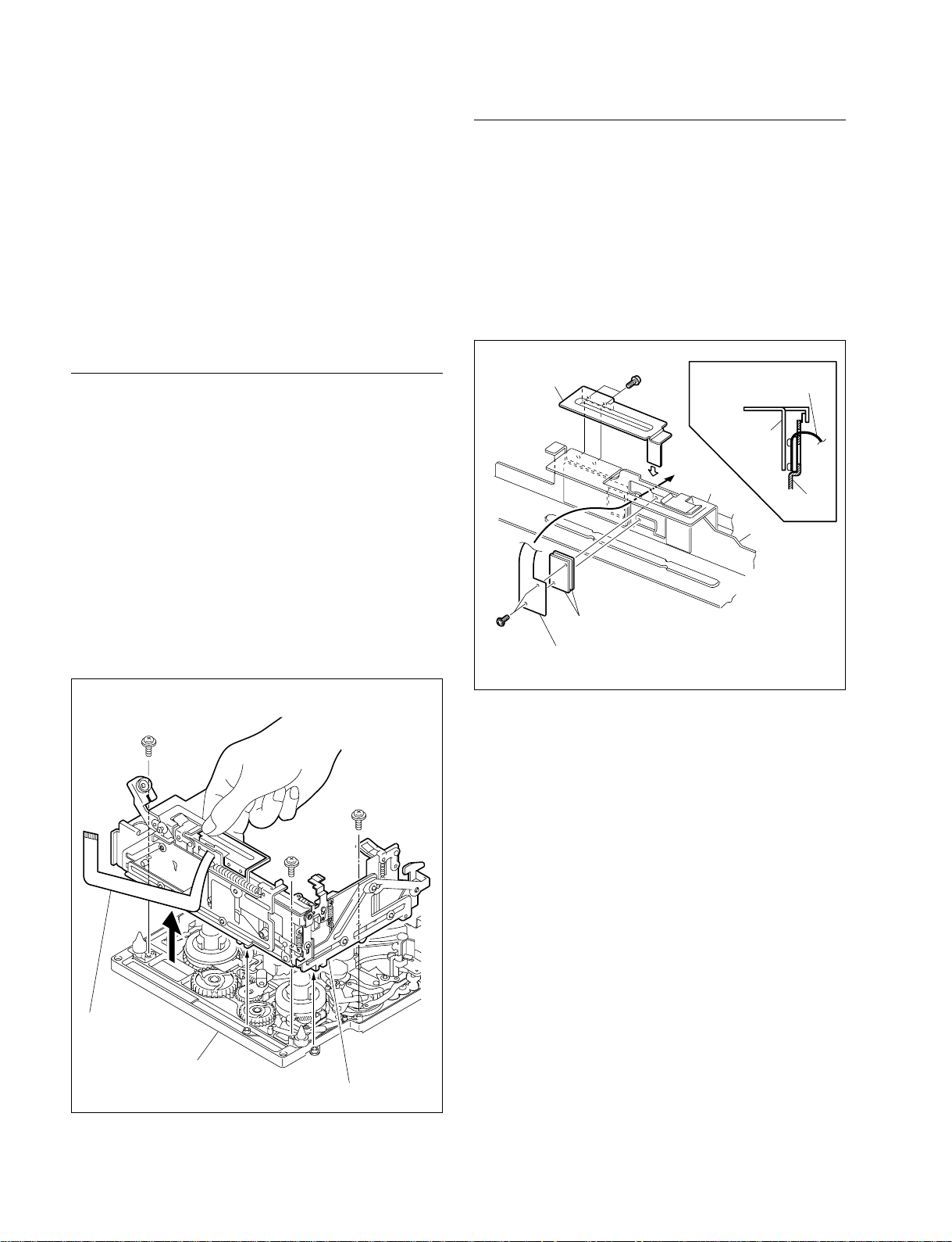
2-6. Cassette Compartment Assembly Removal and Installation
2-6. Cassette Compartment Assembly
Removal and Installation
n
After turning off the power, perform removal and installation of the cassette compartment assembly following the
procedures below.
[Reference][Reference]
[Reference]
[Reference][Reference]
The cassette compartment can be removed both in raised
and lowered status.
Removal
1. Remove the front lid and the outside panel.
(Refer to Section 2-1.)
n
Even a slight bend causes a short life of the flexible
board, therefore use extreme care to handle it.
2. Disconnect the antenna flexible board FL-260 from the
CCM-33B board of DC-DC converter and remove it.
(Refer to Section 2-7.)
3. Remove the three screws and hold the portion of the
cassette compartment shown in the figure, then remove
the cassette compartment in the arrow direction.
*
The frame of the unit is not shown in the figure.
Installation
n
Before installing a new cassette compartment, remove then
reattach the two antenna sheets (magnetic sheet) and
reattach the antenna flexible board FL-260.
1. Remove the two screws from a side plate assembly of
a new cassette compartment to remove the stopper
plate.
Stopper plate
M1.4 x 1.6
Antenna flexible board
(FL-260)
M1.4 x 2.5
Antenna sheets (A)
Antenna flexible board
Stopper plate
Side plate
assembly
Stage assembly
Stage
Figure 1
M1.4 x 2.5
Antenna
flexible board
(FL-260)
Mechanism deck
assembly
Cassette compartment assembly
M1.4 x 2.5
M1.4 x 2.5
2. Route the antenna flexible board FL-260 (M1.4 x 1.6)
as shown in the figure and combine the antenna
flexible board with the two antenna sheets (A), then
attach them to the stage assembly. (Refer to Figure 1.)
3. Install the stopper plate with the two screws.
2-16
HDW-F900 P1E2
 Loading...