


HD DIGITAL VIDEOCASSETTE RECORDER
HDW-D2000
OPERATION MANUAL
1st Edition (Revised 1)
[English]

WARNING
WARNING: THIS WARNING IS APPLICABLE FOR
OTHER COUNTRIES.
To prevent fire or shock hazard, do not
expose the unit to rain or moisture.
To avoid electrical shock, do not open
the cabinet. Refer servicing to qualified
personnel only.
THIS APPARATUS MUST BE EARTHED.
This symbol is intended to alert the user to
the presence of important operating and
maintenance (servicing) instructions in the
literature accompanying the appliance.
For the customers in the U.S.A.
This equipment has been tested and found to comply with
the limits for a Class A digital device, pursuant to Part 15 of
the FCC Rules. These limits are designed to provide
reasonable protection against harmful interference when
the equipment is operated in a commercial environment.
This equipment generates, uses, and can radiate radio
frequency energy and, if not installed and used in
accordance with the instruction manual, may cause harmful
interference to radio communications. Operation of this
equipment in a residential area is likely to cause harmful
interference in which case the user will be required to
correct the interference at his own expense.
1.Use the approved Power Cord (3-core mains)/Appliance
Connector/Plug with earthing-contacts that conforms to
the safety regulations of each country if applicable.
2. Use the Power Cord (3-core mains lead)/Plug
conforming to the following ratings, which meets power
supply voltage of each country.
Rating: 10A or more
For the customers in Europe
This product with the CE marking complies with both the
EMC Directive (89/336/EEC) and the Low Voltage Directive
(73/23/EEC) issued by the Commission of the European
Community.
Compliance with these directives implies conformity to the
following European standards:
• EN60065: Product Safety
• EN55103-1: Electromagnetic Interference (Emission)
• EN55103-2: Electromagnetic Susceptibility (Immunity)
This product is intended for use in the following
Electromagnetic Environment(s):
E1 (residential), E2 (commercial and light industrial), E3
(urban outdoors) and E4 (controlled EMC environment, ex.
TV studio).
CAUTION
The apparatus shall not be exposed to dripping or
splashing and no objects filled with liquid, such as vases,
shall be placed on the apparatus.
You are cautioned that any changes or modifications not
expressly approved in this manual could void your authority
to operate this equipment.
The shielded interface cable recommended in this manual
must be used with this equipment in order to comply with
the limits for a digital device pursuant to Subpart B of Part
15 of FCC Rules.
WARNING: THIS WARNING IS APPLICABLE FOR USA
ONLY.
If used in USA, use the UL LISTED power
cord specified below.
DO NOT USE ANY OTHER POWER CORD.
Plug Cap Parallel blade with ground pin
(NEMA 5-15P Configuration)
Cord Type SJT, three 16 or 18 AWG
wires
Length Less than 2.5 m (8 ft 3 in)
Rating Minimum 10 A, 125 V
Using this unit at a voltage other than 120V
may require the use of a different line cord or
attachment plug, or both.
To reduce the risk of fire or electrical shock,
refer servicing to qualified service personnel.
CAUTION
The unit is not disconnected from the AC power source
(mains) as long as it is connected to the wall outlet, even if
the unit itself has been turned off.

Table of Contents
Chapter 1
Overview
Chapter 2
Location and Function of
Parts
Chapter 3
Preparations
1-1 Features ........................................................................................... 1-1
1-2 Example System Configuration .................................................... 1-3
2-1 Control Panels ................................................................................ 2-1
2-1-1 Upper Control Panel .............................................................. 2-2
2-1-2 Lower Control Panel .............................................................. 2-3
2-1-3 Switch Panel ........................................................................ 2-14
2-2 Connector Panel ........................................................................... 2-15
3-1 Connections to External Devices................................................... 3-1
3-1-1 Connections to Digital Devices ............................................. 3-1
3-2 Reference Sync Signals .................................................................. 3-2
3-2-1 Selecting Reference Signal Depending on
Operational Status .................................................................. 3-2
3-2-2 Connecting Reference Signals ............................................... 3-3
3-3 Setup ................................................................................................ 3-5
3-4 Superimposed Character Information ......................................... 3-6
3-5 Cassettes .......................................................................................... 3-8
3-5-1 Cassette Types........................................................................ 3-8
3-5-2 Inserting and Ejecting Cassettes ............................................ 3-8
3-5-3 Preventing Accidental Erasure of Recordings ....................... 3-9
3-6 Using a Memory Stick .................................................................. 3-10
3-6-1 Notes on Memory Stick ....................................................... 3-10
Chapter 4
Recording and Playback
Chapter 5
Editing
4-1 Recording ........................................................................................ 4-1
4-1-1 Preparations for Recording .................................................... 4-1
4-1-2 Recording Time Code and User Bit Values ........................... 4-2
4-1-3 Recording Procedure ............................................................. 4-4
4-2 Playback .......................................................................................... 4-5
4-2-1 Preparations for Playback ...................................................... 4-5
4-2-2 Playback Procedures .............................................................. 4-6
4-2-3 Dynamic Motion Control (DMC) Playback ........................ 4-10
5-1 Automatic Editing .......................................................................... 5-1
5-1-1 Overview ............................................................................... 5-1
5-1-2 Switch and Menu Settings ..................................................... 5-2
5-1-3 Selecting the Editing Mode ................................................... 5-3
5-1-4 Setting Edit Points ................................................................. 5-3
5-1-5 Modifying and Deleting Edit Points ...................................... 5-6
5-1-6 Cue-up to Edit Points and Preroll .......................................... 5-7
5-1-7 Preview .................................................................................. 5-7
5-1-8 Carrying Out Automatic Editing............................................ 5-8
5-2 DMC Editing................................................................................. 5-11
5-2-1 Overview of DMC Editing .................................................. 5-11
5-2-2 Carrying Out DMC Editing ................................................. 5-12
5-3 Special Automatic Editing Methods ........................................... 5-13
5-3-1 Quick Editing ....................................................................... 5-13
5-3-2 Continuous Editing .............................................................. 5-13
5-3-3 Standalone Editing ............................................................... 5-14
5-3-4 Manual Editing .................................................................... 5-14
5-3-5 Preread Editing .................................................................... 5-14
Table of Contents 1

Table of Contents
Chapter 6
Shot Mark Function
Chapter 7
Tele-File
Chapter 8
UMID Functions
6-1 Overview ......................................................................................... 6-1
6-2 Shot Mark Operation Menu .......................................................... 6-2
6-3 Shot Mark Operations ................................................................... 6-3
6-3-1 Reading Shot Marks .............................................................. 6-3
6-3-2 Writing Shot Marks................................................................ 6-3
6-3-3 Shot Mark List Operations .................................................... 6-4
6-3-4 Cuing Up to Shot Marks ........................................................ 6-6
6-3-5 Reading In Shot Data ............................................................. 6-7
6-3-6 Sorting Shot Marks ................................................................ 6-8
7-1 Overview of Tele-File Functions ................................................... 7-1
7-2 Opening the Tele-File Menu .......................................................... 7-2
7-3 Tele-File Menu ................................................................................ 7-3
7-3-1 Clip Data Display .................................................................. 7-3
7-3-2 Preroll and Cue Up Using Clip Data ..................................... 7-6
7-3-3 Modifying Clip Data .............................................................. 7-7
7-3-4 Undo/Resume Functions ...................................................... 7-10
7-3-5 Displaying and Modifying Attribute Data ........................... 7-11
8-1 Overview of UMID Functions ....................................................... 8-1
8-2 Recording UMIDs .......................................................................... 8-2
8-3 UMID Output and Display ............................................................ 8-4
8-3-1 UMID Output Settings ........................................................... 8-4
8-3-2 UMID Display ....................................................................... 8-4
Chapter 9
Function Menu
Chapter 10
Setup Menus
Chapter 11
Maintenance and
Inspection
Appendix
9-1 Overview ......................................................................................... 9-1
9-1-1 Function Menu Configuration ............................................... 9-1
9-1-2 Using the Function Menu ...................................................... 9-2
9-2 Function Menu Item List ............................................................... 9-3
10-1 Setup Menu Configuration ........................................................ 10-1
10-2 Setup Menu Operations ............................................................. 10-2
10-3 Items in the Basic Setup Menu .................................................. 10-7
10-4 Items in the Extended Setup Menu......................................... 10-10
11-1 Removing a Cassette When Tape Slack Occurs....................... 11-1
11-2 Head Cleaning............................................................................. 11-1
11-3 Error Messages ........................................................................... 11-2
11-4 Moisture Condensation .............................................................. 11-4
11-5 Regular Checks ........................................................................... 11-5
11-5-1 Digital Hours Meter ........................................................... 11-5
11-5-2 Maintenance Timings ........................................................ 11-6
Specifications......................................................................................... A-1
Index ....................................................................................................... I-1
2 Table of Contents
1-1 Features
Chapter 1 Overview
The HDW-D2000 is a high-definition (HD) digital
videocassette recorder based on the HDCAM format.
This unit uses large scale integrated circuits for signal
processing, and has a simple internal construction,
allowing it to provide functionality at least equivalent
to a conventional VTR in a compact (4U size),
lightweight, and low power consumption design.
In addition to HDCAM format recording and
playback, the unit can also play back tapes recorded in
the Digital Betacam and MPEG IMX formats.
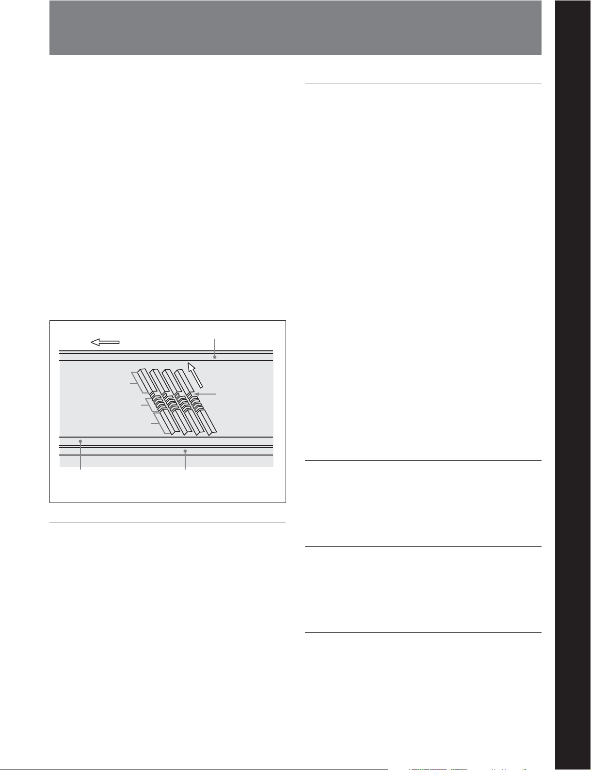
HDCAM format
The HDCAM format uses the same 12.65-mm width
tape as the conventional Betacam series. It provides
high definition images, offering up to two hours of
recording. For video signal compression, prefiltration
and coefficient recording technologies are used.
Direction of tape travel
Video
Audio
Video
CUE track
Direction of head
motion
a)
SAT
High-precision digital signal processing
and range of interfaces
Chapter 1 Overview
The digital signal processing uses HD 4:2:2
component video signals complying with SMPTE
292M, which are converted into parallel data and then
compressed into HDCAM format.
The audio signals are based on AES/EBU format, and
are subjected to digital signal processing without being
compressed.
The unit is equipped with a high definition to standard
definition (HD to SD) downward converter, and has
the following interfaces as standard equipment, for
ease of connection to different external devices.
•SD analog composite signal output
•SD analog component signal output
•Analog audio signal input/output (4 channels)
• HDSDI SMPTE 292M input/output (HD digital
video/audio, 4 channels)
•SDI SMPTE 259M output (component digital video/
audio, 4 channels)
•AES/EBU serial digital audio input/output (4
channels)
•SDTI SMPTE 305M input/output (HDCAM video/
audio data) (Option)
• Time code input/output
• CUE audio input/output
Control (CTL) track
a) Supplemental Automatic Tracking signal
Time code track
High-performance heads and compatibility
functions
The newly developed high-performance heads and
dynamic tracking (DT) technology provide highdensity recording and playback in narrow tracks with
high reliability. The VTR automatically detects the
recording format of tapes when they are loaded, so that
no menu settings need to be made when changing
formats.
High quality four-channel audio
High quality 20 bit/48 kHz AES/EBU digital audio is
supported. There are four digital audio input/output
channels, and four analog audio input/output channels.
Multifunction control panel
While built in a compact 4U size, this unit has a front
panel which provides a wide range of functions while
maintaining existing operability.
Basic operation buttons and jog/shuttle
dial
The basic buttons and jog/shuttle dial for VTR and
editing operations are provided in the conventional
VTR layout, ensuring continuity with conventional
operating panels.
Chapter 1 Overview 1-1

1-1 Features
Chapter 1 Overview
Time data display
This can be selected to display a CTL counter value,
time code value, or time code user bits. It can also
display edit points and edit durations.
Menu-based control interface
The time data/menu display shows not only various
values and settings, but also the pages of a menu
system for commonly used functions. You can use the
function keys and MULTI CONTROL knob to easily
change settings.
High quality variable speed playback and
digital jog sound function
In HDCAM, Digital Betacam or MPEG IMX format
playback, the dedicated playback DT heads allow
smooth, noiseless playback.
In slow motion operation, the digital jog sound
function provides the same ease of operation as for a
conventional analog VTR.
Wide range of editing functions
By combining two units, you can carry out both
assemble editing and insert editing automatically. All
of the necessary editing functions are provided to set
and amend edit points, to preview and review results of
editing, and so on.
DMC editing
This allows automatic editing with a varying playback
speed memorized beforehand for an edit segment.
Preread editing
This allows you to play back prerecorded video and
audio material, edit it by applying effects with an
external device, and then rerecord in real time on the
same tape.
Cross-fade editing
In audio editing, to avoid unnatural effects at edit
points, you can fade the audio track. You can select
cut-in, fade-in, fade-out, or cross-fade.
Downward converter function
The unit has an HD-to-SD downward converter
function, and can output standard definition SDI,
analog component and analog composite signals even
while playing back an HDCAM format tape.
Upward converter function
The unit features a standard definition to high
definition (SD-to-HD) upward converter as standard
equipment. This allows high-quality HD signals to be
output even when playing back tapes recorded in
formats other than HDCAM.
Tele-File functions
Tele-File enables data writing/reading between
cassettes with memory labels and VTRs. It increases
the efficiency of operations such as recording,
playback and editing, and source data management.
Remote control function
Split editing
In insert editing, this allows editing with the audio IN
and OUT points to be displaced from the video edit
points.
1-2 Chapter 1 Overview
This unit can be controlled from an external remote
controller or editor through an interface complying
with RS-422A (serial 9-pin). Since two remote control
connectors are provided, you can also control a
number of VTRs simultaneously.
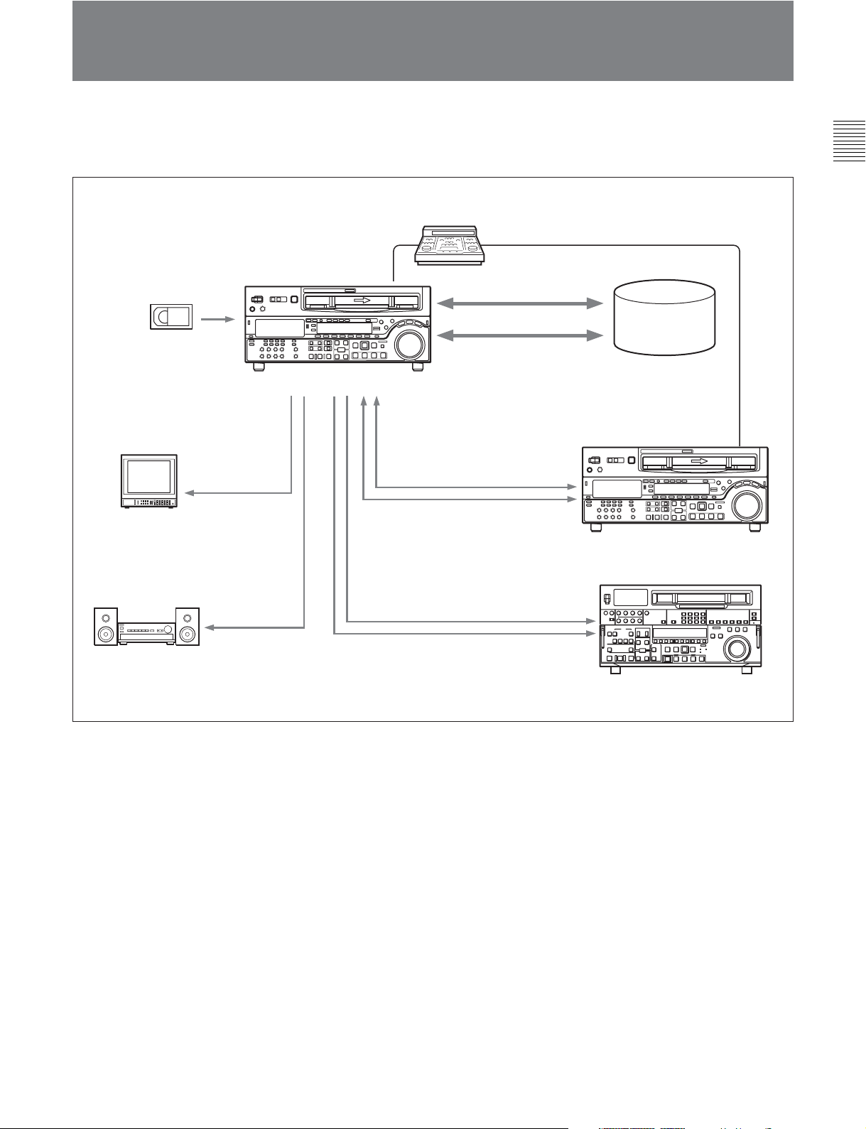
1-2 Example System Configuration
The following conceptual diagram shows an example
of use.
BVE-series editor
SDTI (optional)
Chapter 1 Overview
Tape control
Digital cassette
Video monitor
Audio monitor
HDSDI/Analog
composite
Analog audio
HDW-D2000
HDSDI
HDSDI
SDTI (optional)
Analog composite/component
SDI
Audio/video
server system
HD VTR
SD VTR
Chapter 1 Overview 1-3
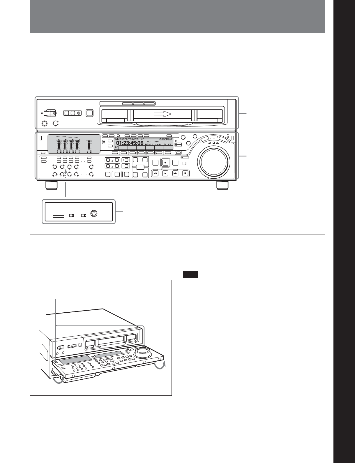
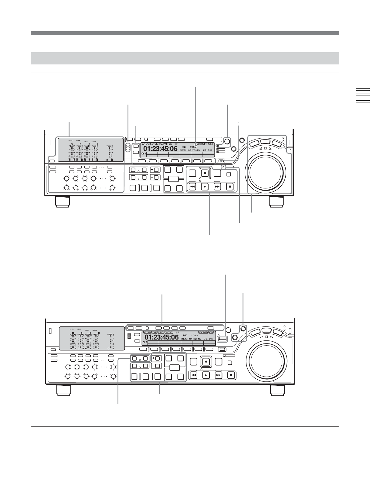
2-1 Control Panels
There are three control panels, as follows:
•Upper control panel
• Lower control panel
•Switch panel
Z
PB/EE CONFI
VID. IN
SDI
EE
DISABL
59.94
CTL/TC
TC
MENU
TCGSET
Upper control panel
Lower control panel
Chapter 2 Location and Function of Parts
Chapter 2 Location and Function of Parts
(see page 2-2)
(see page 2-3)
KEY INHI
ON
PANEL SEL
OFF
CONTROL PANEL
FRONTREAR
Switch panel (access by opening the lower control panel)
To open the lower control panel
Push in the lower control panel unlock buttons to open
the lower control panel. You can fix the lower control
panel in any of five positions between vertical and
horizontal.
Lower control panel unlock buttons
(see page 2-14)
To close the lower control panel
Push up the folding levers on both sides at the same
time allowing the lower control panel to close.
Note
When closing the lower control panel, be careful not to
catch your fingers in the panel.
Chapter 2 Location and Function of Parts 2-1
2-1 Control Panels
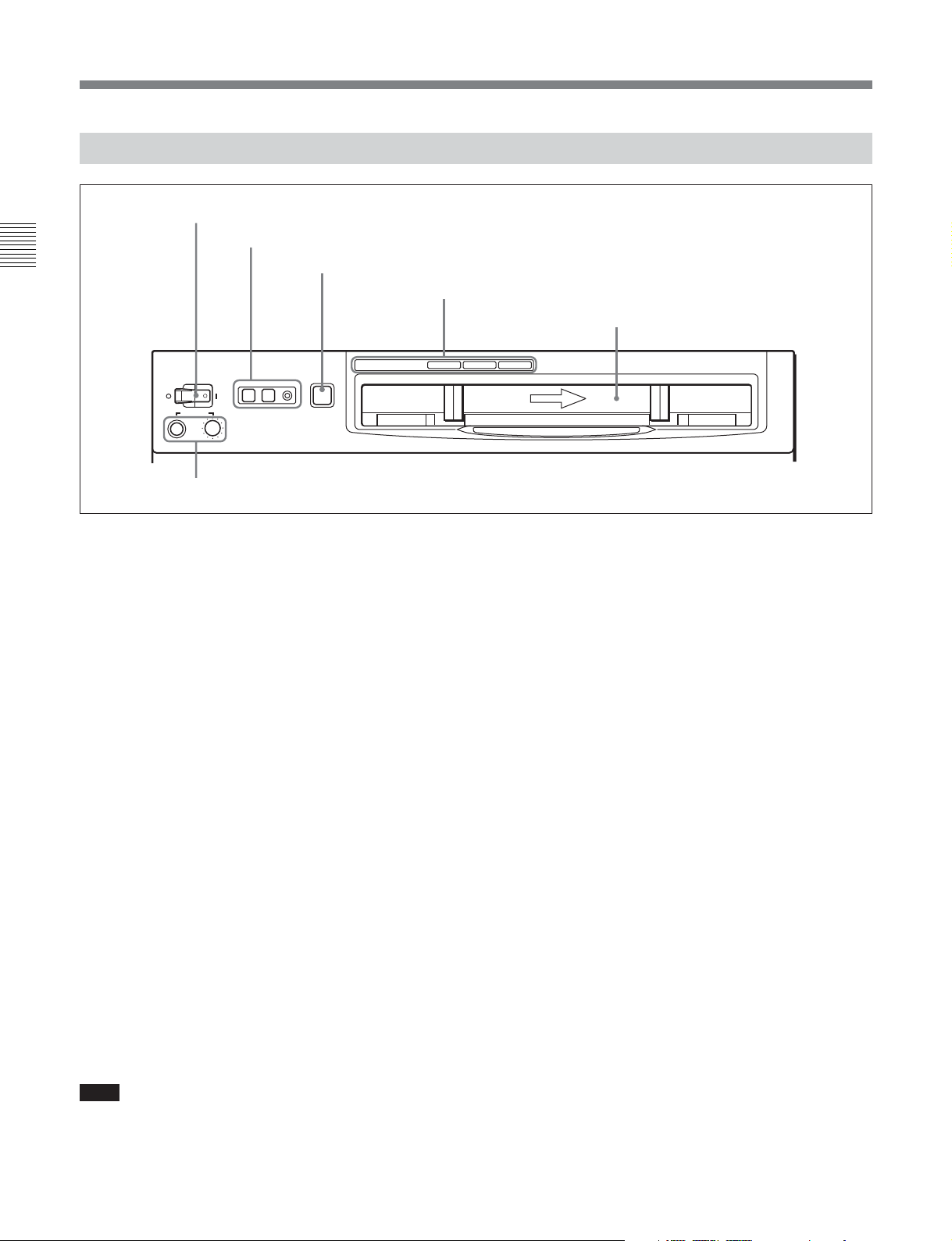
2-1-1 Upper Control Panel
Chapter 2 Location and Function of Parts
1 POWER switch
2 REMOTE buttons and RS-232C indicator
3 EJECT button
POWER
PHONES
5 PHONES jack and control
REMOTE
1(9P) 2(50P) RS-232C
EJECT
Z
4 Format indicators
Digital BETACAM
MPEG IMX
HDCAM
Cassette compartment
1 POWER switch
Pressing the ‘ ) ’ side of the switch powers the unit on.
When the unit is powered on, the audio setting display
section (see page 2-4) and the time data/menu display
section (see page 2-7) light.
2 REMOTE buttons and RS-232C indicator
Press the 1 (9P) button or 2 (50P) button to select the
device controlling this unit.
1(9P): This unit is controlled by the device connected
to the REMOTE 1-IN(9P) or REMOTE
1-OUT(9P) connector. The button lights when
pressed.
2(50P): This unit is controlled by the device
connected to the REMOTE 2 PARALLEL
I/O(50P) connector. The button lights when
pressed.
RS-232C indicator: This indicator lights when this
unit is controlled through the RS-232C connector.
3 EJECT button
To eject the cassette, press this button. While the
cassette is being ejected, this button lights.
When using the lower control panel as remote control
panel, press the DELETE button and STOP button at
the same time to eject the cassette.
4 Format indicators
The indicator (MPEG IMX, Digital BETACAM, or
HDCAM) corresponding to the current recording or
playback format lights.
5 PHONES jack and control
Connect stereo headphones with an impedance of
8 ohms, to monitor the sound during recording,
playback and editing.
The control knob adjusts the volume.
It is possible to set an internal board switch so that the
output volume from the MONITOR OUTPUT L and R
connectors is controlled simultaneously.
For details, refer to the Installation Manual.
Note
Ejecting with the EJECT button is a local operation. It
is not possible to eject a cassette in another unit by
remote control.
2-2 Chapter 2 Location and Function of Parts
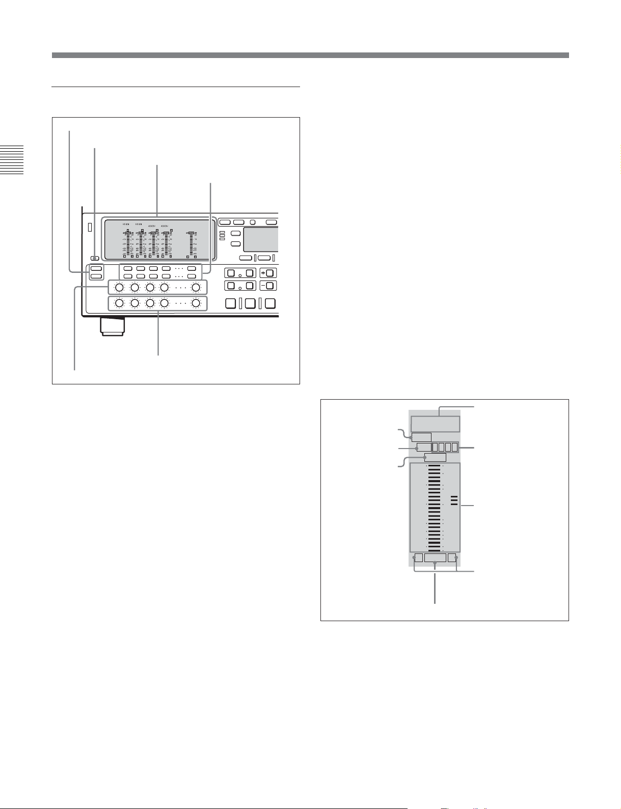
2-1-2 Lower Control Panel
1 Audio control section
(see page 2-4)
2 CHANNEL CONDITION
indicator
(see page 2-6)
3 Menu control buttons
(see page 2-6)
EE
SDI
DISABL
4 Time data/menu display section
5 MULTI CONTROL knob and PUSH/
SHIFT indicator
6 RESET button
59.94
CTL/TCTCMENUVID. IN PB/EE CONFI
TCGSET
8 REC INHI indicator
9 Tape transport control section
(see page 2-7)
(see page 2-8)
(see page 2-8)
7 Search control section
(see page 2-10)
(see page 2-10)
Chapter 2 Location and Function of Parts
(see page 2-8)
VID. IN PB/EE CONFI
SDI
qd Editing control section
qf Shot mark section
q; Editing mode setting
section
(see page 2-11)
59.94
DISABL
CTL/TCMENU
TC
EE
TCGSET
(see page 2-13)
qa ALARM indicator and KEY INHI
indicator
(see page 2-12)
qs PLAYER button and RECORDER
button
(see page 2-12)
(see page 2-12)
Chapter 2 Location and Function of Parts 2-3
2-1 Control Panels
1 Audio control section
1 Audio selection function selector buttons
2 DISPLAY FULL/FINE button
Chapter 2 Location and Function of Parts
5 REC controls
3 Audio setting display section
4 Audio monitor
signal selection
buttons
6 PB controls
For information about how to operate in input signal
selection mode, mixing setting mode, and monitor signal
selection mode, see the descriptions of the audio monitor
signal selection buttons 4 on page 2-5.
2 DISPLAY FULL/FINE button
Pressing this button toggles the display mode of the
level meters in the audio setting display section
between FULL and FINE.
FULL: The display covers the range –60 dB to 0 dB
or –40 dB to +20 dB as selected using setup menu
item 806. In this mode the segment of the display
corresponding to the current audio level and all
lower segments light.
FINE: The display is enlarged, with a step of
0.25 dB. A segment indicating the reference level
lights. In this mode only the segment of the
display corresponding to the current audio level
lights. If the audio level exceeds the maximum
display level, the top segment flashes, and if the
audio level goes below the minimum display
level, the bottom segment flashes.
1 Audio selection function selector buttons
INPUT (input signal selection mode) button:
Pressing this button puts the unit into input signal
selection mode. In the audio setting display
section, indicators flash to indicate the currently
selected signal for each channel (HDSDI, SDTI,
AES/EBU, or ANA). In this state, you can use the
audio monitor signal selection buttons to select the
signal to input to each channel.
Pressing this button again takes the unit out of
input signal selection mode and puts it into
monitor signal selection mode.
MIXING (mixing setting mode) button: Pressing
this button puts the unit into mixing setting mode.
In the audio setting display section, the MIX
indicator flashes. In this state, you can use the
audio monitor signal selection buttons to specify
which input channel signal will be recorded on
which audio track on the tape.
Pressing this button again takes the unit out of
mixing setting mode and puts it into monitor
signal selection mode.
3 Audio setting display section
Input signal indicator
DATA indicator
MIX indicator
OVER indicator
HDSDI SDTI
AES/EBU/ANA
5678
DATA
MIX 1 2 3 4
OVER
dB dB
-10
-20
-30
-40
-60
L R
20
0
2
10
1
0
-1
-10
-20
-2
-40
EMPH
EMPH indicator
Input channel
indicator
Level meter
Monitor channel L
and R indicators
Input signal indicator: Indicates the currently
selected input signal (HDSDI, SDTI, AES/EBU,
or ANA for analog) for the corresponding audio
input channel.
2-4 Chapter 2 Location and Function of Parts

DATA indicator: Lights when the audio output
signals are recognized as data with the unit in
1)
recording, E-E
, or playback mode.
MIX (mixing) indicator: Flashes when a mixing
setting operation is enabled for the corresponding
audio track. The indicator showing the number of
the selected input channel lights.
OVER indicator: While the unit is in recording or
playback mode, this lights when the level of the
audio signal on the corresponding channel exceeds
the maximum level that can be indicated on the
level meter.
Level meter: Displays the audio signal level when
the unit is in recording or playback mode. You can
use the setup menu to switch the display mode
between PEAK.0 (0 dB is maximum level) and
REF.0 (0 dB is the reference level). You can also
use the DISPLAY FULL/FINE button 2 to
enlarge the display only near the reference level.
Input channel indicator: Indicates the input channel
from which audio signals are recorded on the
audio track. Two numbers light to indicate that
signals from the corresponding input channels are
mixed for recording.
Monitor channel L and R indicators: Indicate
whether or not the signals of the track are output
to the MONITOR OUTPUT L/R connectors and
PHONES jack. ‘L’ lights to indicate output to the
left monitor channel, and ‘R’ lights to indicate
output to the right monitor channel.
EMPH (emphasis) indicator: While the unit is in
recording or playback mode, this lights when the
emphasis setting is on for the audio signal on the
corresponding track.
4 Audio monitor signal selection buttons (CH1 to
CH4, and CUE)
The function of these buttons depends on the signal
selection mode set with the audio selection function
selector buttons (INPUT, MIXING) 1 as follows.
Input signal selection mode (the input signal
indicator flashes): The buttons in the upper row
select signals for each audio input channel.
When the CH1 to CH4 buttons are pressed, the
selected signal cycles between HDSDI t AES/
EBU t ANA(LOG) t HDSDI.
Mixing setting mode (the MIX indicator flashes):
The buttons in the lower row (REC row) select the
tracks (audio channels on the tape) to contain the
mixed signals. In the audio setting display section,
the MIX indicator for the corresponding track
flashes. The buttons in the upper row (EXT row)
select the input channel signals to record on the
corresponding track. By pressing two buttons at
the same time, you can specify that the signals of
two input channels be mixed for recording.
For example, if you want to record the mixed
signals of input channels 1 and 4 on track 3, press
the CH3 button in the lower row (REC row), and
then simultaneously press the CH1 and CH4
buttons in the upper row (EXT row). The settings
for signal mixing become valid when the MIXING
button is pressed.
Note
Before selecting signals from two input channels
for recording in one recorder channel, check to be
sure that the emphasis settings (ON or OFF) of the
two input channels are the same. Recording and
playback of mixed signals cannot be carried out
correctly if the emphasis settings are different.
The EMPH indicator in the audio setting display
section lights for channels with the emphasis
setting on.
Monitor signal selection mode (the input signal
indicator and the MIX indicator do not flash):
The buttons in the upper and lower rows select
tracks to be output to the MONITOR OUTPUT L
and R connectors on the connector panel or the
PHONES jack on the upper control panel. The
buttons in the upper row (L row) select tracks for
output to the MONITOR OUTPUT L connector,
and the buttons on the lower row (R row) select
tracks for output to the MONITOR OUTPUT R
connector. You can obtain the mixed output of
multiple tracks by simultaneously pressing
multiple buttons in the upper or lower rows. For
example, simultaneously press the CH1, CH2, and
CH3 buttons in the upper row to mix the signals of
audio tracks 1, 2, and 3 for output to the
MONITOR OUTPUT L connector.
Chapter 2 Location and Function of Parts
..........................................................................................................................................................................................................
1) E-E mode: Abbreviation of “Electric-to-Electric mode”.
In this mode, video and audio signals input to the VTR
are output after passing through internal electric circuits,
but not through magnetic conversion circuits such as
heads and tapes. This can be used to check input signals
and for adjusting input signal levels.
Chapter 2 Location and Function of Parts 2-5

2-1 Control Panels
To monitor CH5 to CH8 in MPEG IMX playback,
press the CUE button to switch between CH1 to
CH4 and CH5 to CH8, and then select the desired
channels.
5 REC (recording) controls
Chapter 2 Location and Function of Parts
These individually adjust the recording levels on
channels 1 to 4, and cue audio.
To set the recording level, put the unit into E-E mode,
press to protrude the control knobs and adjust the level
while watching the level meters.
When the control knobs are pushed in, the recording
levels return to the preset levels and cannot be
adjusted.
For details about selecting the E-E mode, see the
description of the REC button in the tape transport control
section (see page 2-10) and function menu HOME page (see
page 9-3).
6 PB (playback) controls
These adjust individually the playback levels on
channels 1 to 4, and cue audio.
During playback, press to protrude the control knobs
and adjust the level while monitoring the audio level
indication on the level meters in the audio setting
display section.
When the control knobs are pushed in, the playback
levels return to the preset levels, and cannot be
adjusted.
2 CHANNEL CONDITION indicator
A three-color indicator shows the state of the playback
signal.
Green: The state of the playback signal is good.
Yellow: The playback signal is somewhat
deteriorated, but playback is possible.
Red: The playback signal is deteriorated.
When this indicator remains on, head cleaning or
an internal inspection is necessary.
3 Menu control buttons
These buttons are used for function menu (see the
following section “Overview of the function menu”)
and setup menu (see Chapter 10) operations. The page
buttons (V, v, and HOME) select menu pages, and the
function buttons (F1 to F6) make function settings.
V: Selects the next page in the order HOME t 1 t
2 t 3 t 4 t 5 t 6 t HOME.
v: Selects the next page in the order HOMEt6 t5
t 4 t 3 t 2 t 1 t HOME.
HOME: Selects the function menu HOME page.
When at least one user-defined function key is set in
the HOME2 page, pressing the HOME button
toggles the menu page display between HOME
and HOME2.
F1 to F6: Make settings for the items displayed in the
upper line of the menu display (the menu item
display line). Pressing one of these buttons
changes the setting for the corresponding item and
displays the setting in the lower line of the menu
display.
If there is no setting displayed in the lower line of
the menu display, even though a menu item is
displayed in the upper line, pressing the
corresponding function button moves to a lower
menu level.
Overview of the function menu
The function menu provides convenient access to
frequently used function settings, such as input video
signal selection and time code settings.
For details on the function menu, see Chapter 9.
2-6 Chapter 2 Location and Function of Parts
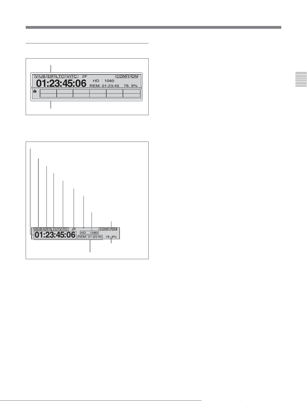
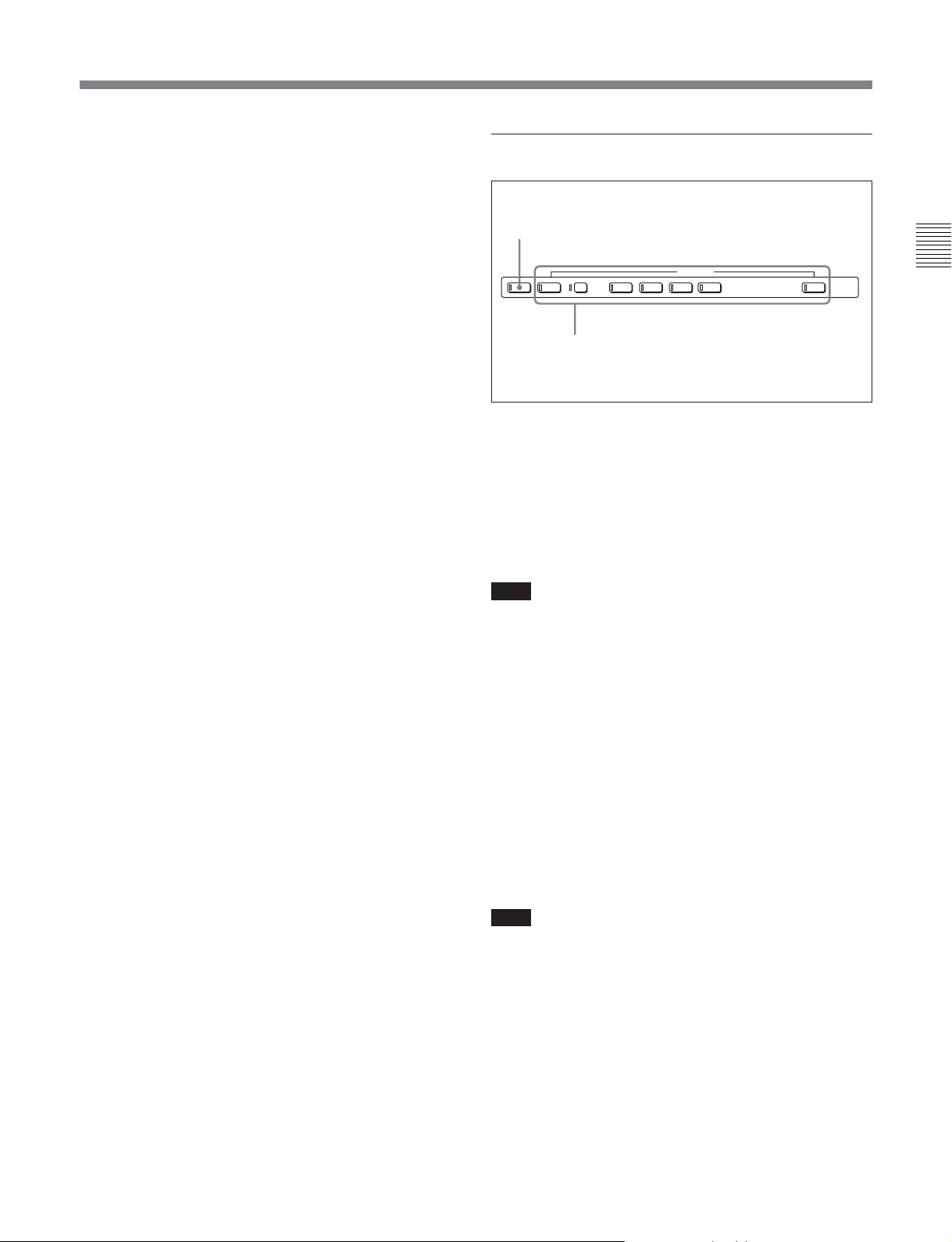
4 Time data/menu display section
1 Time data display
59.94
1
SDI
EE
DISABL
CTL/TC
TC
MENUVID. IN PB/EE CONFI
TCGSET
Time data type indicator
This indicates the type of data displayed in the time
data display area 1.
LTC (longitudinal time code): Time code recorded
on a longitudinal track on the tape
LUB: LTC user bit values
VITC (vertical interval time code): Time code
recorded in the vertical blanking interval
VIUB: VITC user bit value
Chapter 2 Location and Function of Parts
2 Menu display
1 Time data display
This displays indicators relating to time data and other
indicators.
Time data display area 1
Time data type indicator
DF indicator
LTC indicator
VITC indicator
Capstan lock mode indicator
System frequency indicator
Tape format/line standard indicator
CONFI (ON)/PREREAD
indicators
59.94
Speed indication
Time data display area 2
area
Time data display area 1
Normally this displays a CTL count, time code value,
or user bit value according to the setting in function
menu HOME page for F4 (CTL/TC).
DF (drop-frame) indicator (for 59.94i, 29.97PsF
mode only)
This lights when values of drop-frame mode time code
are displayed.
LTC indicator
Regardless of the display in the time data display
area 1, this indicator lights when LTC values are being
read or recorded.
VITC indicator
Regardless of the display in time data display
area 1, this indicator lights when VITC values are
being read or recorded.
Capstan lock mode indicator
This indicates the capstan lock mode (2F or 4F) set in
function menu page 4 or in setup menu item 106.
System frequency indicator
This indicator shows the current system frequency.
Tape format/line standard indicator
This shows information about the tape format and the
line standard conversion status.
Following are some examples and their meanings.
IMX 1080: Signals recorded in MPEG IMX format
are output after conversion to 1080 line standard
format signals.
DB 1035: Signals recorded in Digital Betacam format
are output after conversion to 1035 line standard
format signals.
1035t1080: HDCAM signals recorded in 1035 line
standard format are output after conversion to
1080 line standard signals.
HD 1080: HDCAM signals recorded in 1080 line
standard format are output with no change.
Chapter 2 Location and Function of Parts 2-7
2-1 Control Panels
CONFI (ON)/PREREAD indicators
These indicate the state of the VTR CONFI playback
function. When the CONFI playback function is
enabled, the CONFI indicator appears, and when
CONFI playback is actually being carried out the ON
indicator also appears.
Chapter 2 Location and Function of Parts
When F6 (PREREAD) is set to ON in function menu
page 4, the CONFI playback function is disabled and
one of the following is displayed.
PREREAD: Preread of both audio and video
A-PREAD: Preread of audio only
V-PREAD: Preread of video only
Speed indication area
This indicates the speed of a DMC playback.
During a DMC playback, “DMC SPD” is displayed in
time data display area 2. However, CONFI playback is
not possible during editing.
Time data display area 2
Displays data types and time data such as the time
code of edit points and the total time of that tape.
The following data types are shown.
TOTL: Total time of the tape.
REM: Remaining time on the tape.
Depending on the setting of F5 (T INFO) in function
menu page 3, either TOTL (TOTAL) or REM
(REMAIN) is displayed.
The values displayed are approximate values
calculated on the basis of the detected tape diameter.
They are not precise to units of seconds.
The following appear when the top or end of the tape
is reached.
BOT: Returned to top of tape.
EOT: Reached end of tape.
IN: video IN point
OUT: video OUT point
AIN: audio IN point
AOUT: audio OUT point
DUR: duration value
TCG (time code generator): time code generated by
the internal time code generator
2 Menu display
1)
This displays the function menu and setup menu.
For details on the function menu, see Chapter 9 and for
details on the setup menu, see Chapter 10.
5 MULTI CONTROL knob and PUSH/
SHIFT indicator
In function menu operations, rotate the MULTI
CONTROL knob to change settings that flash in the
menu display section. In setup menu operations, rotate
this knob to select menu items.
The PUSH/SHIFT indicator lights when you press this
knob in. In this state, the value of the setting changes
by a greater amount when you rotate the knob.
6 RESET button
To reset a CTL, time code (TC) or user bit (UB) value
displayed in time data display area 1, hold this button
down.
Resetting the CTL value erases all edit points.
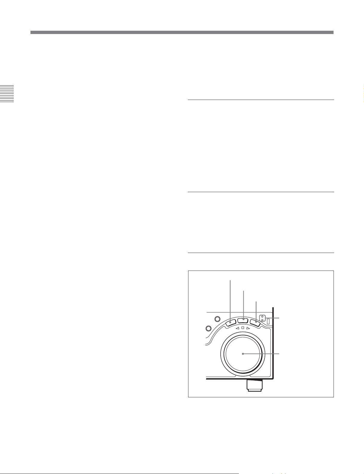
7 Search control section
1 SHUTTLE button
2 JOG button
3 VAR button
JOG
SHUTTLE/VAR
VA
R
FORWARD
JOG
4 SHUTTLE/VAR
and JOG
indicators
5 Search dial
RECORDER
SHUTTLE
REVERSE
..........................................................................................................................................................................................................
1) CONFI playback: This refers to playback of the audio
and video signals immediately after recording, using the
and purposes simultaneously with recording. This is used
to check recording.
confidence heads, the signal being output to all intents
2-8 Chapter 2 Location and Function of Parts

1 SHUTTLE button
To use the search dial for playback in shuttle mode,
press this button, turning it on.
For details of playback in shuttle mode, see the description
of the search dial 5.
2 JOG button
To use the search dial for playback in jog mode, press
this button, turning it on.
For details of playback in jog mode, see the description of
the search dial 5.
3 VAR (variable) button
To use the search dial for playback in variable speed
mode, press this button, turning it on.
For details of playback in variable speed mode, see the
description of the search dial 5.
4 SHUTTLE/VAR and JOG indicators
Either of the indicators is lit to show the current search
mode or the mode used last.
When the SHUTTLE/VAR indicator is lit: Shuttle
or variable speed mode
When the JOG indicator is lit: Jog mode
When the unit is turned on, the SHUTTLE/VAR
indicator lights.
5 Search dial
Turn this to carry out playback in the modes shown in
the following table. Turning the dial clockwise lights
the H indicator and plays back in the forward
direction. Turning the dial counterclockwise lights the
h indicator and plays back in the reverse direction.
When the tape is stopped or the unit is turned on, the
s indicator lights. Pressing the dial toggles between
shuttle and jog modes or between variable speed and
jog modes.
Depending on the tape format, noiseless playback is
possible in the following ranges.
HDCAM: –1 to +2 times normal speed
Digital Betacam: –1 to +3 times normal speed
MPEG IMX: –1 to +3 times normal speed
Playback modes using the search dial
Playback mode
Shuttle
Jog Press the JOG button or the search
Variable speed Press the VAR button, turning it on,
Capstan override
Operations and functions
Press the SHUTTLE button or the
search dial so that the SHUTTLE
button lights, then turn the search dial.
Playback is carried out at a speed
determined by the position of the
search dial. Playback speed ranges
are as follows.
• HDCAM: ±50 times normal speed
(59.94i, 29.97PsF mode), ±58 times
normal speed (50i, 25PsF mode),
±60 times normal speed (24PsF,
23.98PsF mode)
• Digital Betacam: ±50 times normal
speed
• MPEG IMX: ±78 times normal speed
The search dial has detents at the still
position and at ±5 times normal
speed.
The maximum shuttle mode playback
speed can be changed by changing
the setting of setup menu item 102
(see page 10-10)
dial so that the JOG button lights, then
turn the search dial. Playback is
carried out at a speed determined by
the speed of rotation of the search
dial. The playback speed range is ±1
time normal speed.
The search dial has no detents.
then turn the search dial. You can
control the playback speed finely in
the range in which noiseless playback
is possible.
• HDCAM: Maximum 51 steps
• Digital Betacam , MPEG IMX:
Maximum 54 steps
The search dial has detents at the still
position and at the normal speed
position.
For details on operation, see page
4-8.
.
Setting setup menu item 101 (see page 10-10) to KEY
enables you to use only the SHUTTLE, JOG, and VAR
buttons to select shuttle/jog/variable speed modes.
Chapter 2 Location and Function of Parts
Chapter 2 Location and Function of Parts 2-9
2-1 Control Panels
8 REC INHI (recording inhibit) indicator
This indicator is on or off according to the
combination of the F5 (RECINH) setting on function
menu page 4 and the record inhibit plug on the
cassette, as shown in the following table. When this
Chapter 2 Location and Function of Parts
indicator is on, recording on tape is prohibited.
RECINH setting
ON
OFF Record inhibit Lit
a) It is possible to make a setting (setup menu item 107) so
that in this case the indicator flashes.
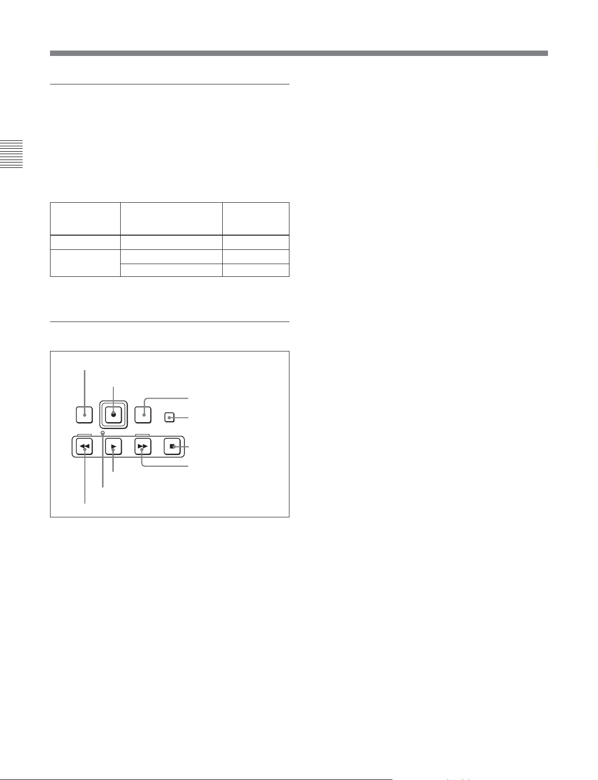
9 Tape transport control section
1 PREROLL button
PREROLL
REW
1 PREROLL button
Press this button to cue up to the preroll point (before
the IN point by the time set as the preroll time) on the
tape. You can change or select the preroll time and the
state of the unit at the end of preroll (“stop mode”
still playback mode) using setup menu item 001 or
401.
REC
PLAY
8 SERVO indicator
9 REW button
REC INHI indicator indications
State of the record
inhibit plug on the
cassette
Record inhibit/permit Lit
Record permit
2 REC button
EDIT
STANDBY
F FWD
7 PLAY button
3 EDIT button
4 STANDBY button
STOP
5 STOP button
6 F FWD button
REC INHI
indicator state
a)
Off
1)
or
Cuing up edit points
Hold down the IN, OUT, AUDIO IN, or AUDIO OUT
button while pressing this button to cue up to the
corresponding edit point.
2 REC (record) button
To start recording, press this button together with the
PLAY button, turning it on.
Monitoring in E-E mode
When the unit is in stop mode, pressing the REC
button lights the button and allows you to monitor the
video and audio in E-E mode. To return to the original
state, press the STOP button.
During playback, search, fast forward, or rewind,
holding down the REC button allows you to monitor
the video and audio in E-E mode. In this case the
button does not light.
3 EDIT button
To carry out manual editing, press this button
simultaneously with the PLAY button.
Monitoring in E-E mode
When the unit is in stop mode, pressing the EDIT
button lights the button and allows you to monitor the
input signal selected with the ASSEMBLE button or
INSERT buttons in E-E mode. To return to the original
state, press the STOP button.
During playback, search, fast forward, or rewind,
holding down the EDIT button allows you to monitor
the video and audio input signals in E-E mode.
4 STANDBY button
When this button is off with a cassette inserted in the
unit, to put the unit in standby mode, press the button,
turning it on.
In standby mode, the drum is rotating and the tape is in
contact with the drum. As a result, recording or
playback can start immediately.
To end standby mode, press the STANDBY button,
turning it off.
If 8 minutes (value can be varied using setup menu
item 501) elapse in standby mode, the unit
automatically switches out of standby mode to protect
the tape.
..........................................................................................................................................................................................................
1) Stop mode: The state in which the currently operated
device is stopped and the STOP button is lit.
2-10 Chapter 2 Location and Function of Parts
5 STOP button
To stop recording or playback, press this button,
turning it on.
When you stop playback, the unit switches either to
still playback or to E-E mode according to the setting
on function menu HOME page for F2 (PB/EE) and the
setting of setup menu item 108.
Fault display function
The STOP button flashes in the following cases related
to reference signals:
•When F2 (OUTREF) is set to INPUT on function
menu page 4, and there is no input video signal.
•When F2 (OUTREF) is set to REF in function menu
page 4, and there is no external reference signal input
or the input external reference signal is not
synchronized to the input video signal.
6 F FWD (fast forward) button
To fast forward the tape, press this button, turning it
on.
q; Editing mode setting section
1 ASSEMBLE button
VIDEO
TC
CH1
2 INSERT buttons
1 ASSEMBLE button
Press this button, turning it on, to carry out assemble
1)
editing
.
All signals (video signals, audio signals, time code
signals, and so on) are recorded together.
Press the button again, turning it off, to exit from
assemble editing mode.
INSERTASSEMBLE
CH2
CH3
CH4
CUE
Chapter 2 Location and Function of Parts
7 PLAY button
To start playback, press this button, turning it on.
To operate in capstan override mode
Hold down this button, and turn the search dial.
For details of capstan override mode, see page 4-8.
8 SERVO indicator
Lights when the drum servo and capstan servo are
locked.
9 REW (rewind) button
To rewind the tape, press this button, turning it on.
Note
When even one of the INSERT buttons is lit, the
ASSEMBLE button does not work. To use the
ASSEMBLE button, turn off all the lit INSERT
buttons.
2 INSERT buttons
Press the corresponding button, turning it on, to select
2)
a signal for insert editing
. Press the button again,
turning it off, to cancel the selection.
VIDEO button: Selects the video signal.
TC (time code) button: Selects time code.
CH1 to CH4 (audio channels 1 to 4) buttons:
Select the signals on audio channels 1 to 8.
CUE button: Selects the cue audio signal.
Note
When the ASSEMBLE button is lit, none of the
INSERT buttons work. To use INSERT buttons, press
the ASSEMBLE button, turning it off.
..........................................................................................................................................................................................................
1) Assemble editing: Editing in which new video/audio is
added in sequence to the end of existing recorded video/
audio.
2) Insert editing: Editing in which new video/audio is added
to an intermediate position of existing recorded video/
audio.
Chapter 2 Location and Function of Parts 2-11
2-1 Control Panels
qa ALARM indicator and KEY INHI
indicator
ALARM indicator
This lights when a hardware error is detected on the
unit, and goes off when the error is resolved.
Chapter 2 Location and Function of Parts
When this indicator is lit, an error message appears in
the time data/menu display section. If you are using
the HDSDI OUTPUT 3 (SUPER), SDI OUTPUT 3
(SUPER) or COMPOSITE VIDEO OUTPUT 3
(SUPER) connector, then when the setting of F4
(CHARA) in function menu page 4 is ON, the error
message also appears on the monitor screen.
For details on error messages, refer to Section 1-24 in the
Maintenance Manual Volume 1.
KEY INHI (inhibit) indicator
This indicator lights when the KEY INHI switch on
the switch panel (see page 2-14) is set to ON.
qs PLAYER button and RECORDER
button
When you carry out editing using a VTR connected to
the REMOTE 1-IN(9P) or REMOTE 1-OUT(9P)
connector (see page 2-18) as the player and this unit as
the recorder, these buttons select which VTR the
editing control buttons and tape transport buttons on
this unit control.
PLAYER: The editing control buttons and tape
transport buttons on this unit control the external
player VTR.
RECORDER: The editing control buttons and tape
transport buttons on this unit control the recorder
(this unit).
When this unit is being used in standalone mode,
neither button functions.
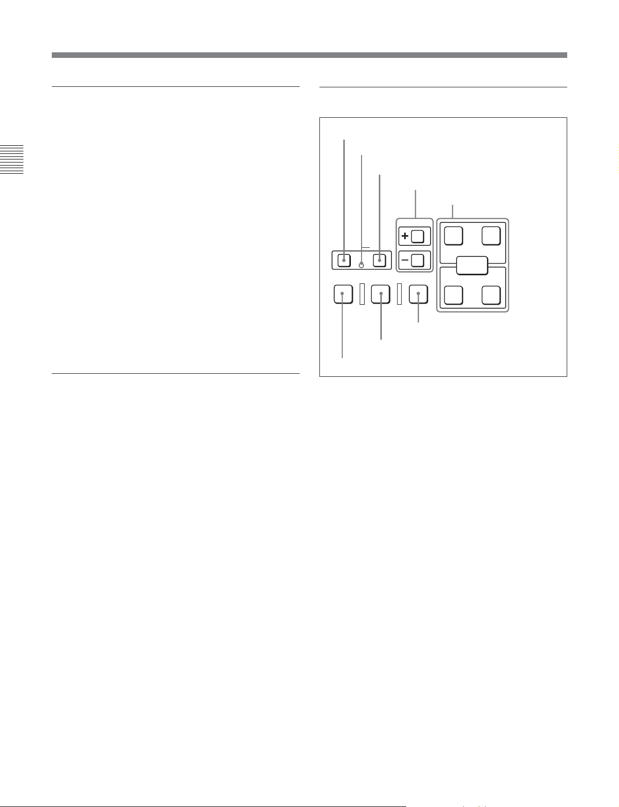
qd Editing control section
1 DMC EDIT button
2 MEMORY indicator
3 DELETE button
4 TRIM buttons
5 Edit point setting buttons
TRIM
AUDIO
IN OUT
DMC EDIT
PREVIEW REVIEWAUTO EDIT
8 PREVIEW button
1 DMC EDIT button
Use this button to memorize the playback speed varied
between –1 and +2 times normal speed, and carry out
automatic playback or automatic editing using the
memorized playback speed.
2 MEMORY indicator
When memorizing the playback speed using the DMC
EDIT button, this indicator flashes as the playback
speed is captured to memory, and lights continuously
once the speed is captured.
3 DELETE button
This deletes an existing edit point.
Hold down this button and press the IN, OUT, AUDIO
IN, or AUDIO OUT button which is lit, indicating an
existing edit point, to delete the corresponding edit
point. The button either goes off or flashes. When the
button flashes, it is necessary to set the deleted edit
point again.
To cancel the DMC mode, hold down the DMC EDIT
button and press the DELETE button.
DELETE
MEMORY
7 AUTO EDIT button
ENTRY
IN OUT
6 REVIEW button
2-12 Chapter 2 Location and Function of Parts

4 TRIM buttons
Use these buttons to trim an edit point to single-frame
precision.
Hold down the IN, OUT, AUDIO IN, or AUDIO OUT
button, and press one of these buttons. The ‘+’ button
advances the corresponding edit point by one frame,
and the ‘–’ button sets it back by one frame.
Pressing one of these buttons while holding down the
PLAY button adjusts the tape speed by +8% or –8%
correspondingly. (Capstan override function)
5 Edit point setting buttons
IN button and OUT button
To set a video IN point or OUT point, hold down the
IN button or OUT button and press the ENTRY
button.
After you have made the setting, pressing the IN
button or OUT button displays the video IN point or
video OUT point set in time data display area 2.
7 AUTO (automatic) EDIT button
After edit point setting, to carry out automatic editing
(recording), press this button, turning it on.
If the IN point is not set, the automatic editing is
carried out with the point where you pressed this
button as the IN point.
If you pressed the PREVIEW button to carry out a
preview, when the preview ends this button flashes.
8 PREVIEW button
After edit point setting, to preview the editing results
on the monitor before recording, press this button,
turning it on.
If the IN point is not set, the preview is carried out
with the point where you pressed this button as the IN
point.
During the preview it is lit, and when the preview ends
it flashes.
Chapter 2 Location and Function of Parts
AUDIO IN button and AUDIO OUT button
In insert editing, to set an audio IN point or audio OUT
point separate from the corresponding video edit point,
hold down the AUDIO IN button or AUDIO OUT
button, and press the ENTRY button.
After you have made the setting, pressing the AUDIO
IN button or AUDIO OUT button displays the audio
IN point or audio OUT point set in time data display
area 2.
ENTRY button
Use this for setting edit points and so on.
• To set a video IN point or OUT point: Hold down
the IN button or OUT button, and press this button.
• To set an audio IN point or OUT point: Hold down
the AUDIO IN button or AUDIO OUT button, and
press this button.
6 REVIEW button
Use this button to review the editing results after
carrying out automatic editing.
qf Shot mark section
1 LIST button
LIST GOOD SHOT MARK
REC/
ERASE
1 LIST button
Use this button to read in and list shot marks.
2 REC/ERASE indicator
This lights in the state in which writing, amending, and
deleting of shot marks is enabled and flashes while a
shot mark is actually being written, amended or
deleted.
3 MARK button
Hold this button down for 2 seconds or more, to enable
writing, amending, and deleting of shot marks.
2 REC/ERASE indicator
3 MARK button
Chapter 2 Location and Function of Parts 2-13
2-1 Control Panels
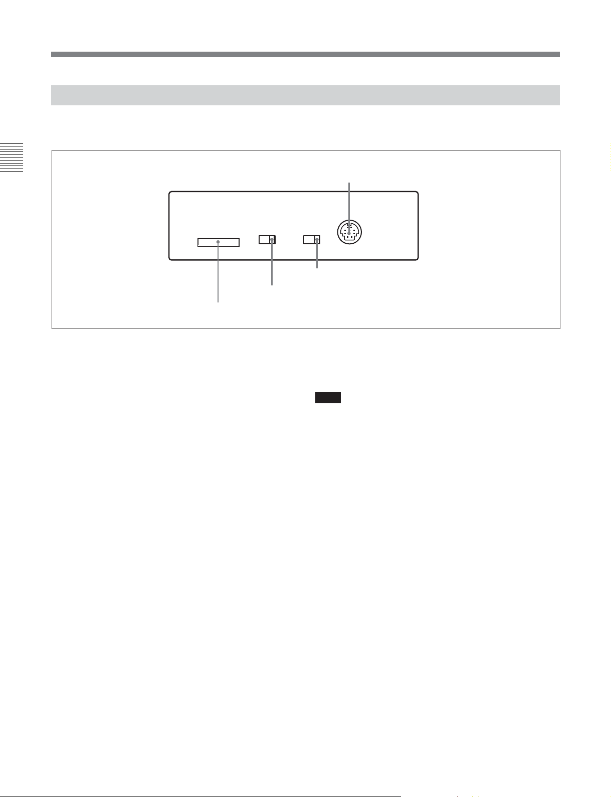
2-1-3 Switch Panel
To access the switch panel, open the lower control
panel.
Chapter 2 Location and Function of Parts
1 CONTROL PANEL connector (10-pin, round
type)
Plug in the lower control panel connection cable.
2 PANEL SELECT switch
In addition to the lower control panel, you can connect
a similar control panel to this unit. When two control
panels are connected to the unit, the PANEL SELECT
switch is used to specify which panel be enabled to
control the unit.
FRONT: Enables the control panel connected to the
CONTROL PANEL connector on the switch
panel.
REAR: Enables the control panel connected to the
CONTROL PANEL connector on the connector
panel. When setup menu item 117 is set to PARA,
this switch position also enables the control panel
connected to the CONTROL PANEL connector
on the switch panel.
KEY INHI
OFF
ON
3 KEY INHI switch
4 Memory stick slot
On how to open the lower control panel, see the figure on
page 2-1.
1 CONTROL PANEL connector
CONTROL PANEL
PANEL SEL
FRONTREAR
2 PANEL SELECT switch
4 Memory stick slot
Use this to update the firmware. You can also save or
load setup menu settings onto the memory stick.
Note
After inserting a memory stick, allow at least five
seconds to elapse before removing it.
For details on firmware update and save or load setup menu
settings, refer to the Maintenance Manual Volume 1.
3 KEY INHI switch
Moving this switch to the ON position disables the
controls on the upper and lower control panels.
You can specify which buttons and knobs are disabled
in setup menu item 118.
2-14 Chapter 2 Location and Function of Parts
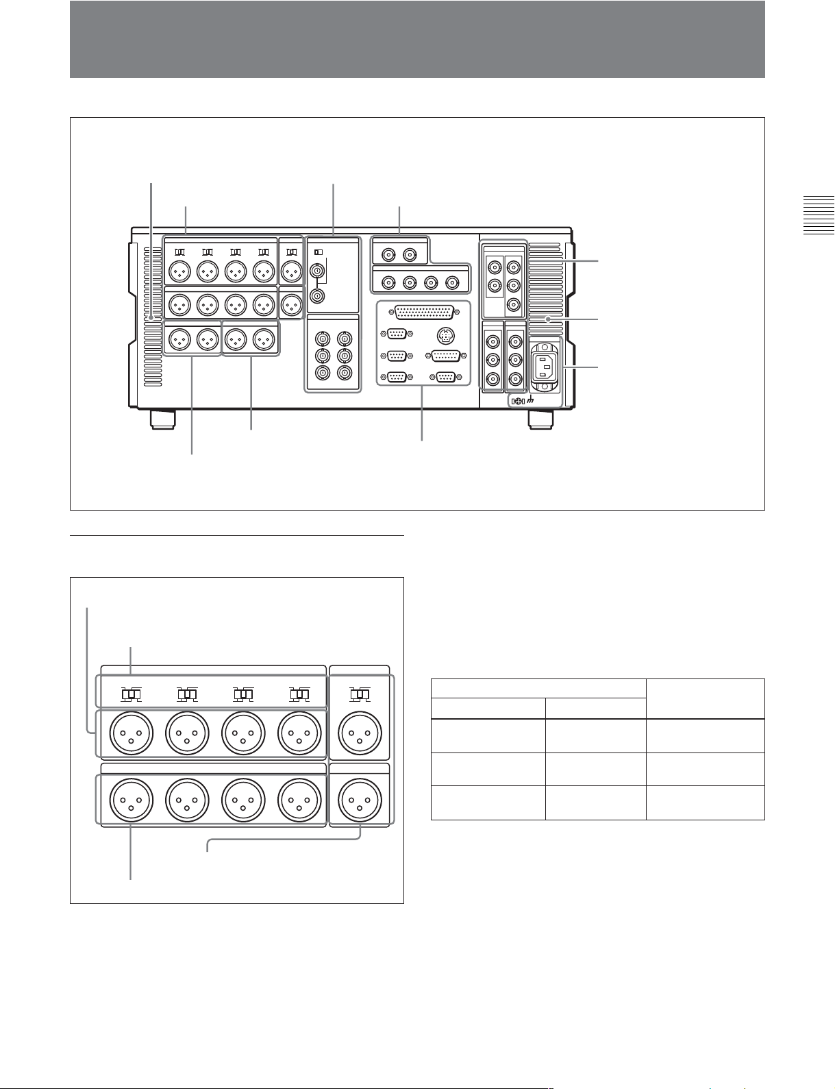
2-2 Connector Panel
Cooling fan
2 Analog video input/output section
1 Analog audio input/output
section
75Ω
7 Time code input/output
section
(see page 2-18)
8 Audio monitor signal output section
(see page 2-18)
1 Analog audio input/output section
1 AUDIO INPUT CH1 to CH4 connectors
2 AUDIO INPUT CH1 to CH4 LEVEL switches
(see page 2-16)
3 Digital audio input/output section
(see page 2-16)
4 Digital signal input/
output section
page 2-17)
Cooling fan
5 Power supply section
(see page 2-17)
6 External device connectors
(see page 2-17)
2 AUDIO INPUT CH1 to CH4 (channels 1 to 4)
LEVEL switches
Set these for each channel as shown in the following
table, according to the audio input levels to the
AUDIO INPUT CH1 to CH4 connectors and the
impedance.
Chapter 2 Location and Function of Parts
(see
CH1
CH1
LOW
OFF
LEVEL
HIGH
ON
600Ω
AUDIO INPUT CUE
CH2
LOW
OFF
CH3
LEVEL
HIGH
ON
600Ω
AUDIO OUTPUT
LOW
OFF
LEVEL
HIGH
ON
600Ω
CH4
LOW
LEVEL
OFF
HIGH
ON
600Ω
IN
LEVEL
LOW
HIGH
ON
OFF
600Ω
CUE
OUTCH2 CH3 CH4
4 CUE IN/OUT connectors
3 AUDIO OUTPUT CH1 to CH4 connectors
1 AUDIO INPUT CH1 to CH4 (channels 1 to 4)
connectors (XLR 3-pin, female)
Input analog audio signals to channels 1 to 4.
You can record analog audio signals input to these
connectors to any audio track on the tape.
AUDIO INPUT CH1 to CH4 LEVEL switch settings
Audio input level and impedance Switch setting
Level
–60 dBu
(microphone input)
+4 dBu
(line audio input)
+4 dBm
(line audio input)
Impedance
High impedance
(approx. 20 kΩ)
High impedance
(approx. 20 kΩ)
LOW-OFF
(left position)
HIGH-OFF
(center position)
600 Ω HIGH-ON 600Ω
(right position)
3 AUDIO OUTPUT CH1 to CH4 (channels 1 to 4)
connectors (XLR 3-pin, male)
These connectors output analog audio signals for
channels 1 to 4.
4 CUE IN/OUT (cue audio input/output)
connectors (XLR 3-pin, female/male)
The IN connector inputs and the OUT connector
outputs the cue audio signals.
Chapter 2 Location and Function of Parts 2-15
2-2 Connector Panel
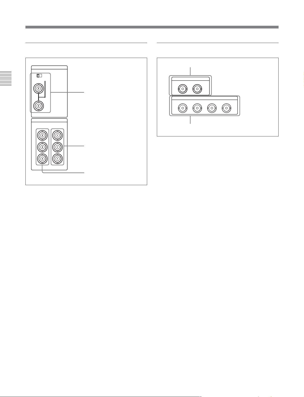
2 Analog video input/output section
REF INPUT
INPUT 1125/525
OFF ON
75Ω
Chapter 2 Location and Function of Parts
VIDEO OUTPUT
COMPOSITE COMPONENT
1
2
3
(SUPER)
1 REF. (reference) VIDEO INPUT connectors
(BNC type) and 75Ω termination switch
Input a reference video signal. Input a three-valued
(positive and negative) sync signal, a video signal with
chroma burst (VBS) or a monochrome video signal
(VS). When using the loop-through connection set the
switch to the OFF position, and otherwise to the ON
position.
Y
R-Y
B-Y
1 REF.VIDEO INPUT connectors
and 75Ω termination switch
2 COMPONENT VIDEO
OUTPUT connectors
3 COMPOSITE VIDEO
OUTPUT connectors
3 Digital audio input/output section
1 AUDIO INPUT (AES/EBU) connectors
AUDIO INPUT(AES/EBU)
CH1/2 CH3/4
AUDIO OUTPUT(AES/EBU)
CH1/2 CH3/4 CH5/6 CH7/8
2 AUDIO OUTPUT (AES/EBU) connectors
1 AUDIO INPUT (AES/EBU) connectors (BNC
type)
Input two sets (4 channels: CH1/2 and CH3/4) of AES/
EBU format digital audio signals.
2 AUDIO OUTPUT (AES/EBU) connectors (BNC
type)
Output a maximum of 4 sets (8 channels: CH1/2, CH3/
4, CH5/6, CH7/8) of AES/EBU format digital audio
signals.
However, the HDW-2000 supports 2 sets only (4
channels: CH1/2, CH3/4).
2 COMPONENT VIDEO OUTPUT connectors
(BNC type)
These connectors output analog component video
signals (Y/R–Y/B–Y).
3 COMPOSITE VIDEO OUTPUT connectors
(BNC type)
These connectors output analog composite video
signals.
When the setting of F4 (CHARA) in function menu
page 4 is ON, connector 3 (SUPER) outputs a signal
with superimposed time code, menu settings, alarm
messages, and other text information.
2-16 Chapter 2 Location and Function of Parts
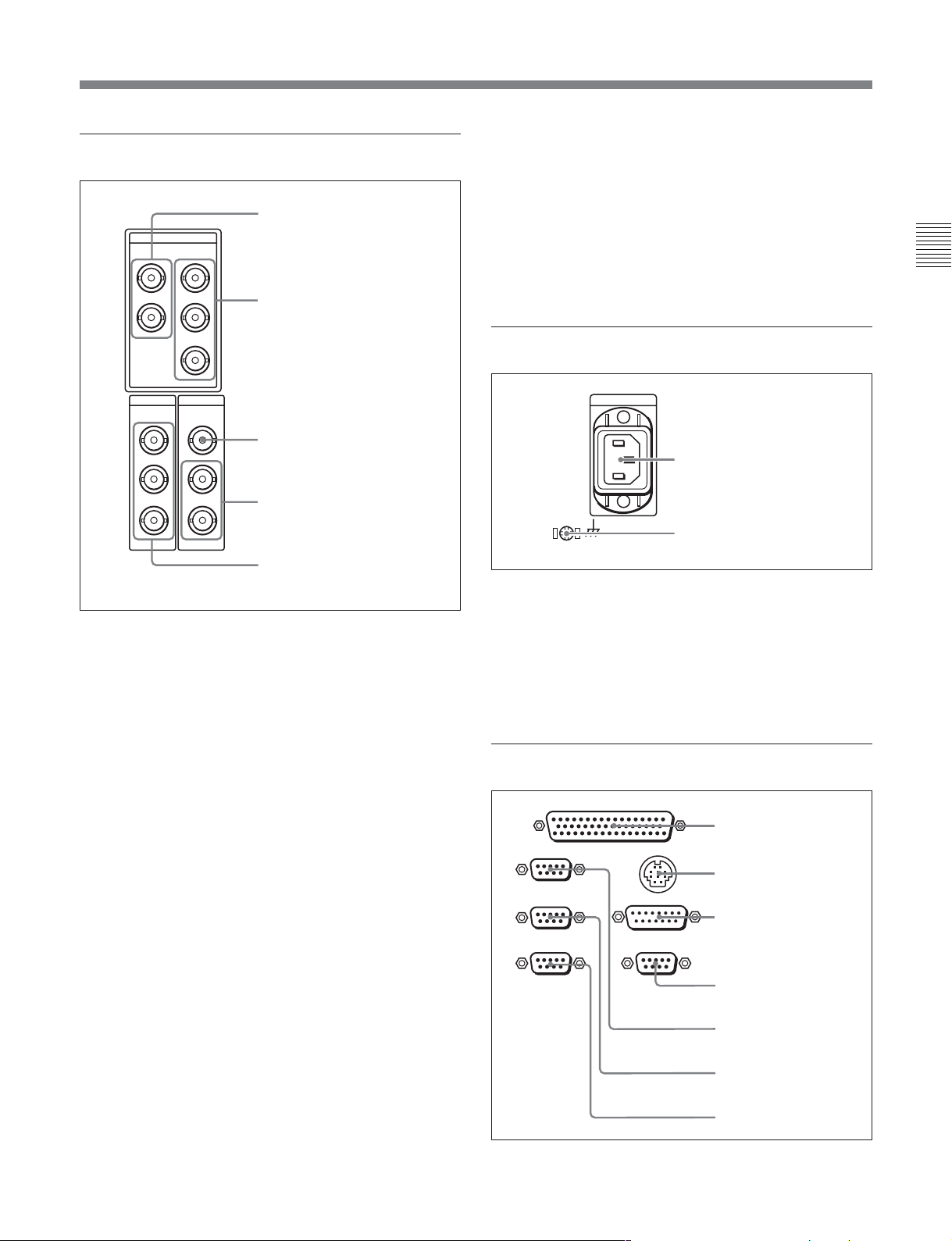
4 Digital signal input/output section
1 HDSDI INPUT connectors
HDSDI
INPUT
OUTPUT
1
INPUT MONITOR
2
3(
SUPER
)
2 HDSDI OUTPUT connectors
5 SDI (Serial Digital Interface) OUTPUT
connectors (BNC type)
These connectors output D1 format video/audio
signals.
When the setting of F4 (CHARA) in function menu
page 4 is ON, connector 3 (SUPER) outputs a signal
with superimposed time code, menu settings, alarm
messages, and other text information.
5 Power supply section
Chapter 2 Location and Function of Parts
SDI
OUTPUT
1
2
SUPER
3(
)
SDTI
INPUT
OUTPUT
1
2
3 SDTI INPUT connector
4 SDTI OUTPUT connectors
5 SDI OUTPUT connectors
1 HDSDI (HD Serial Digital Interface) INPUT
connectors (BNC type)
The upper of these two connectors inputs HD format
video/audio signals. The lower one outputs the input
signals for monitoring.
2 HDSDI (HD Serial Digital Interface) OUTPUT
connectors (BNC type)
These connectors output HD format video/audio
signals. When the setting of F4 (CHARA) in function
menu page 4 is ON, connector 3 (SUPER) outputs a
signal with superimposed time code, menu settings,
alarm messages, and other text information.
3 SDTI (Serial Data Transport Interface) INPUT
connector (BNC type)
Inputs SDTI format video and audio signals.
4 SDTI (Serial Data Transport Interface)
OUTPUT connectors (BNC type)
Output SDTI format video and audio signals.
1 AC IN connector
2 Ground terminal
1 AC IN connector
Use the optional power cord to connect this to an AC
outlet.
2 Ground terminal
Connect this to ground.
6 External device connectors
REMOTE 2 PARALLEL I/O(50P)
1 REMOTE 2 PARALLEL
REMOTE 1-IN(9P)
REMOTE 1-OUT(9P)
RS232C
CONTROL PANEL
VIDEO CONTROL (15P)
VIDEO CONTROL (9P)
I/O(50P) connector
2 CONTROL PANEL
connector
3 VIDEO CONTROL(15P)
connector
4 VIDEO CONTROL(9P)
connector
5 REMOTE 1-IN(9P)
connector
6 REMOTE 1-OUT(9P)
connector
7 RS-232C connector
Chapter 2 Location and Function of Parts 2-17

2-2 Connector Panel
1 REMOTE 2 PARALLEL I/O(50P) connector
(D-sub 50-pin)
Connect remote control signals from an external
device.
For details, refer to the Installation Manual.
Chapter 2 Location and Function of Parts
2 CONTROL PANEL connector (round type, 10pin)
In addition to the lower control panel, a similar control
panel can be connected to this unit. To connect such a
second control panel, use this connector. When two
control panels are connected, use the PANEL SELECT
switch on the switch panel (see page 2-14) to specify
which control panel will control this unit.
3 VIDEO CONTROL(15P) connector (D-sub 15pin)
For remote control of the internal digital video
processor, connect an optional BVR-50/50P Video
Remote Control Unit.
Always power off this unit before connecting the
remote control unit.
4 VIDEO CONTROL(9P) connector (D-sub 9-pin)
For remote control of the internal digital video
processor, connect an optional HKDV-900 Video
Remote Control Unit.
Always power off this unit before connecting the
remote control unit.
5 REMOTE 1-IN(9P) connector (D-sub 9-pin)
When using this unit together with another HDCAM
VTR, and a BVE-series BVE-700/900/910/2000/9000/
9000P/9100/9100P or other editor, connect the
optional 9-pin remote control cable from the other unit
to this connector.
Depending on the setting of setup menu item 211, you
can use this connector alone, or in a loop-through
configuration with the REMOTE 1-OUT(9P)
connector.
6 REMOTE 1-OUT(9P) connector (D-sub 9-pin)
This provides the loop-through output for remote
control signals from the REMOTE 1-IN(9P)
connector.
Depending on the setting of setup menu item 211, you
can use this connector alone, or in a loop-through
configuration with the REMOTE 1-IN(9P) connector.
7 RS-232C connector (D-sub 9-pin)
Use this for monitoring and diagnosis of the state of
this unit from an external computer, using the ISR
(Interactive Status Reporting) function.
7 Time code input/output section
1 TIME CODE IN connector
TIME CODE
IN OUT
2 TIME CODE OUT connector
1 TIME CODE IN connector (XLR 3-pin, female)
To record time code from an external device, input a
time code signal from the time code output connector
of the other device.
2 TIME CODE OUT connector (XLR 3-pin, male)
This outputs a time code according to the operating
state of the unit, as follows:
•During playback: the playback time code
By setting setup menu item 606, you can also output
the time code from the internal time code generator
locked to the playback time code.
•During recording: the time code generated by the
internal time code generator or the time code input to
the TIME CODE IN connector.
8 Audio monitor signal output section
1 MONITOR OUTPUT R
MONITOR OUTPUT
RL
connector
2 MONITOR OUTPUT L
connector
2-18 Chapter 2 Location and Function of Parts

1 MONITOR OUTPUT R connector (XLR 3-pin,
male)
This outputs the audio signals whose output
destination was set to ‘R’ with the audio monitor
signal selection buttons in the audio control section. If
multiple tracks have been set to ‘R’, the signals of
those tracks are mixed for output.
2 MONITOR OUTPUT L connector (XLR 3-pin,
male)
This outputs the audio signals whose output
destination was set to ‘L’ with the audio monitor signal
selection buttons in the audio control section. If
multiple tracks have been set to ‘L’, the signals of
those tracks are mixed for output.
Chapter 2 Location and Function of Parts
Chapter 2 Location and Function of Parts 2-19
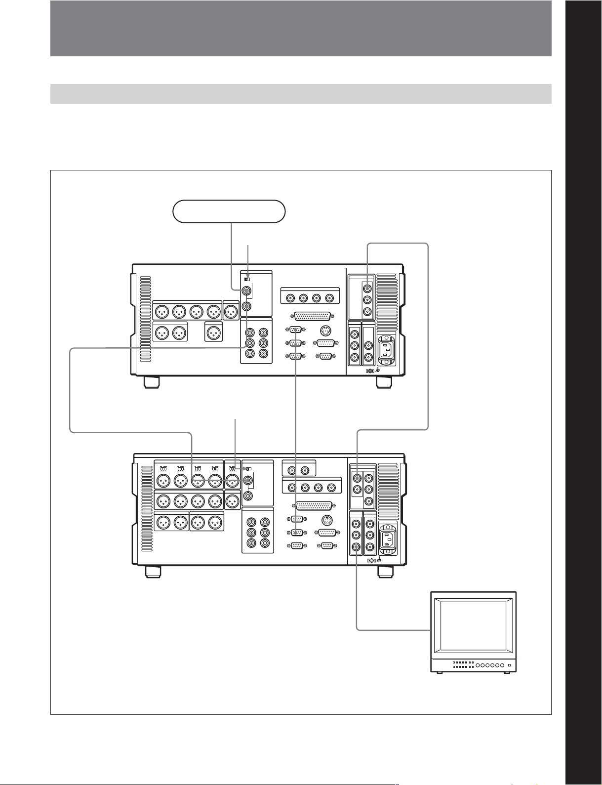
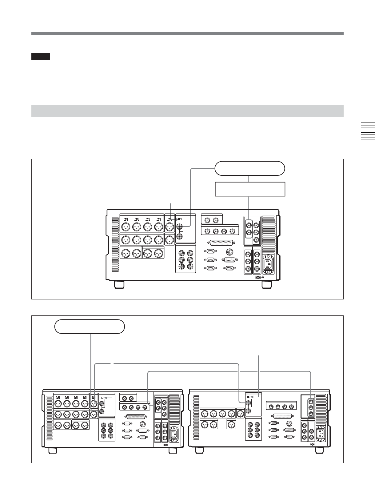
3-1 Connections to External Devices
3-1-1 Connections to Digital Devices
Chapter 3 Preparations
This unit can input serial digital signals (video and
audio) from another digital VTR such as the HDW500/F500/2100/M2100/M2100P. The following
Reference signal
75 Ω termination
switch: OFF
REF. VIDEO INPUT
75Ω
REF. VIDEO
INPUT
HDW-M2100/M2100P (player)
75Ω termination
switch: ON
example shows the connections with another HDWM2100/M2100P unit as a player, with this unit used as
recorder.
Chapter 3 Preparations
HDSDI OUTPUT
REMOTE 1-IN(9P)
REF. VIDEO INPUT
HDW-D2000 (recorder)
REMOTE
1-OUT(9P)
75Ω
SDI OUTPUT 3
(SUPER)
HDSDI INPUT
BVM-D24 series video
monitor
Chapter 3 Preparations 3-1

3-2 Reference Sync Signals
This section describes how reference signals for the
video output signals and servo system are selected.
The output from the internal reference video signal
The reference signal selection switches automatically
between REF and INPUT depending on the menu
Chapter 3 Preparations
a) EE: In E-E mode
generator is supplied to the output video signal and
servo circuits as a reference signal.
3-2-1 Selecting Reference Signal Depending on Operational Status
settings and the operating status of the unit, as shown
in the following table.
F2 (OUTREF) setting
— EXT NORMAL EE REF
REF AUTO1 NORMAL EE
INPUT — EE
REF AUTO2 NORMAL EE REF
INPUT — EE
PB: Playing back (normal playback, jog mode, shuttle
mode, variable-speed mode, and also stop mode)
EDIT: Edit preset enabled
REC: Recording
Menu item 309 setting
Menu item 334 setting
INPUT EE INPUT
INPUT EE
INPUT EE
Unit’s operational
a)
status
PB
EDIT
REC
PB REF
EDIT
REC
PB
EDIT
REC INPUT
PB REF
EDIT
REC INPUT
PB
EDIT
REC
PB
EDIT INPUT
REC
PB REF
EDIT INPUT
REC
PB
EDIT
REC
Reference signal
setting
3-2 Chapter 3 Preparations
Notes
•When there are no HD-SDI signal or SDTI signal
(option) input whereas INPUT is selected for
OUTREF, the unit synchronizes to the input
reference video signal.
•When there is no reference video signal input
whereas REF is selected for OUTREF, no external
reference signal is used. In this case, the unit
synchronizes to the internally generated reference
signal.
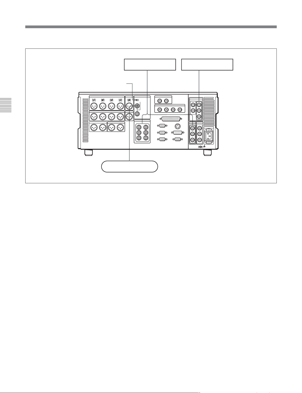
3-2-2 Connecting Reference Signals
Connect reference signals as shown below, according
to the way in which the unit is to be used.
•Connections for recording from a switcher or signal generator
Switcher or signal generator
Chapter 3 Preparations
Reference signal
75 Ω termination switch: ON
HDW-D2000
REF. VIDEO
INPUT
75Ω
•Connections for recording from an external VTR (player)
Reference signal
75 Ω termination switch: OFF
HDSDI INPUT
75 Ω termination switch: ON
REF. VIDEO
INPUT
HDW-D2000 (recorder)
HDSDI INPUT
REF. VIDEO
INPUT
HDW-M2100/M2100P (player)
HDSDI OUTPUT
Chapter 3 Preparations 3-3
3-2 Reference Sync Signals
•Connections for playback
HD video monitorSD video monitor
Chapter 3 Preparations
75 Ω termination switch: ON
HDW-D2000
Reference signal
• SDI OUTPUT
• COMPOSITE
• COMPONENT
75Ω
REF. VIDEO INPUT
HDSDI OUTPUT
3-4 Chapter 3 Preparations

3-3 Setup
The principal setup operations before operating this
unit can be carried out using setup menus.
The setup menus of this unit comprise a basic setup
menu and an extended setup menu. The contents of
these menus are as follows.
Basic setup menu:
• Items relating to the hours meter
• Items relating to operation
• Items relating to menu banks
Extended setup menu:
• Items relating to control panels
• Items relating to the remote control interface
• Items relating to editing operations
• Items relating to preroll
• Items relating to tape protection
• Items relating to the time code generator
• Items relating to video control
• Items relating to audio control
• Items relating to digital processing
For detailed information about the items, except for the
basic setup menu items relating to the hours meter, of these
menus and how to use them, see Chapter 10 “Setup Menus”.
For detailed information about menu operations relating to
the hours meter, see Section 11-5-1 “Digital Hours
Meter”(page 11-5).
This unit allows menu settings to be saved in what are
termed “menu banks”. Saved sets of menu settings
can be recalled for use as required.
For more information about the menu banks, see the section
“Menu bank operations (menu items B01 to B13)” (page
10-5) .
Chapter 3 Preparations
Chapter 3 Preparations 3-5

3-4 Superimposed Character Information
When the function menu item CHARA is set to ON,
the video signal output from the HDSDI OUTPUT 3
(SUPER) connector, SDI OUTPUT 3 (SUPER)
connector, or COMPOSITE VIDEO OUTPUT 3
(SUPER) connector contains superimposed character
information, including time code, menu settings, and
alarm messages.
Information displayed
Chapter 3 Preparations
Adjusting the character display
You can adjust the position, size and type of the
superimposed characters using setup menu items 002,
003, 005, 009, and 011.
For details, see Section 10-3 “Items in the Basic Setup
Menu” (page 10-7).
1 Type of time data
Time data
2 Time code reader drop frame mark
(for 59.94i, 29.97PsF mode only)
3 Time code generator drop frame mark
(for 59.94i, 29.97PsF mode only)
4 VITC field mark
TCR . 23 : 5 9 . 4 0 . 1 8 *
PSHUTTLESTILL
5 Recorder/player selection
Note
The display shown above corresponds to the factory
default settings of the unit.
Changing the setting of setup menu item 005 allows
different time data to be displayed in the lower line of
the display.
For details, see Section 10-3 “Items in the Basic Setup
Menu” (page 10-7).
6 Operation mode
1 Type of time data
Display
CTL CTL counter data
TCR LTC reader time code
UBR LTC reader user’s bits
TCR. VITC reader time code
UBR. VITC reader user’s bits
TCG Time code generator time code
UBG Time code generator user’s bits
IN IN point
OUT OUT point
AI Audio IN point
AO Audio OUT point
DUR Duration between any two of the four edit
Meaning
points (IN, OUT, audio IN, audio OUT)
3-6 Chapter 3 Preparations
Note
If the time data or user’s bits cannot be read correctly,
they will be displayed with an asterisk. For example,
“T*R”, “U*R”, “T*R.” or “U*R.”.

2 Time code reader drop frame mark (for 59.94i,
29.97PsF mode only)
“.”: Indicates drop frame mode
“:”: Indicates non-drop-frame mode
3 Time code generator drop frame mark (for
59.94i, 29.97PsF mode only)
“.”: Indicates drop frame mode (factory preset)
“:”: Indicates non-drop-frame mode
4 VITC field mark
“ ” (blank): Fields 1 and 3 (for 59.94i, 29.97PsF
mode) or fields 1, 3, 5 and 7 (for 50i, 25PsF
mode)
“ * ”: Fields 2 and 4 (for 59.94i, 29.97PsF mode) or
fields 2, 4, 6 and 8 (for 50i, 25PsF mode)
5 Recorder/player selection
The indication changes as follows, according to the
state of the RECORDER/PLAYER buttons on the
control panel.
No display: Neither the RECORDER nor PLAYER
button is lit.
P: The PLAYER button is lit.
R: The RECORDER button is lit.
6 Operation mode
The field is divided into three blocks, A, B and C.
•Block A displays the operation mode.
•Block B displays the servo lock status or tape speed.
•Block C displays a
mark to indicate an edit section
during automatic editing.
Display
Block A Block B
TAPE UNTHREAD Cassette is not loaded.
STANDBY OFF Standby off mode
T.RELEASE Tape tension released
STOP Stop mode
F.FWD Fast forward mode
REW Rewind mode
PREROLL Preroll mode
PLAY Playback mode (servo
PLAY Playback mode (servo locked)LOCK
PLAY Variation
from normal
speed (%)
REC Record mode (servo unocked)
REC LOCK Record mode (servo locked)
EDIT Edit mode (servo unlocked)
EDIT LOCK Edit mode (servo locked)
JOG STILL A still picture in jog mode
JOG FWD Jog mode in forward direction
JOG REV Jog mode in reverse direction
SHUTTLE (Speed) Shuttle mode
VAR (Speed) Variable speed mode
AUTO EDIT Automatic editing mode
PREVIEW Preview mode
REVIEW Review mode
DMC (Speed)
D-PREV (Speed)
D-EDIT (Speed)
DMC-SPD (Speed) DMC initial speed setting
PLY-SPD Variation
from normal
speed
Operation mode
unlocked)
Capstan override mode
page 4-8)
a)
DMC playback speed
a)
DMC editing preview mode
a)
DMC editing mode
Tape speed override mode
(when “TSO” is selected in
setup menu item 111)
(see
Chapter 3 Preparations
A
B
a) Initial speed settings or stored speed settings
C
Chapter 3 Preparations 3-7

3-5 Cassettes
This unit uses the following HDCAM cassettes for
both recording and playback.
The unit can also play back the following cassettes.
Chapter 3 Preparations
•Digital Betacam cassettes
•MPEG IMX cassettes
It is not possible to insert or eject a cassette unless the
unit is powered on.
3-5-1 Cassette Types
HDCAM cassettes
Small cassettes BCT-6HD/12HD/22HD/32HD/40HD
Large cassettes BCT-34HDL/64HDL/94HDL/124HDL
3-5-2 Inserting and Ejecting Cassettes
1 Turn the POWER switch on.
2 Check the following points, then insert the cassette
in the orientation shown in the figure.
• Check that message “ERR-10” is not shown in
the time data/menu display section.
• Check that there is no slack in the tape.
The cassette is drawn into the unit, and the
STANDBY and STOP buttons light.
Removing slack from the tape
Press in one of the reels with a finger, and turn gently
in the direction shown by the arrows until there is no
slack in the tape.
Inserting a cassette
EJECT button
1
STANDBY
F FWDREW
PLAY
STOP
2
Small cassette
Large cassette
STANDBY button
STOP button
Ejecting a cassette
Press the EJECT button.
Note
Ejecting is a local operation. It is not possible to eject a
cassette in another unit by remote control.
If the tape slacks inside the unit, pressing the EJECT button
may not eject the cassette. For information about how to
remove the cassette in such a case, refer to Section 1-17 in
the Installation Manual.
3-8 Chapter 3 Preparations

3-5-3 Preventing Accidental Erasure of Recordings
To prevent a tape from being inadvertently erased,
press in the red record inhibit plug on the cassette.
Large cassette
Small cassette
Press in the red record inhibit plug. (“ON”)
Return this plug to its original position to enable recording on the
tape again. (“OFF”)
Chapter 3 Preparations
Chapter 3 Preparations 3-9

3-6 Using a Memory Stick
When a Memory Stick is inserted in the VTR, the file
data can be stored on the Memory Stick, which
enables you to share data among VTRs.
Use a Memory Stick formatted with this VTR. It
cannot be shared with other devices.
For more details, refer to the Maintenance Manual.
Chapter 3 Preparations
Inserting a Memory Stick
Insert a Memory Stick with the label side up into the
Memory Stick slot until it clicks.
Note
Label side
Types of Memory Stick
There are two types of Memory Stick: MagicGate
Memory Stick that is equipped with the MagicGate
copyright protection technology and general Memory
Stick. Use the general type Memory Stick (8MB,
16MB, 32MB, 64MB, 128MB) with your VTR.
On MagicGate
MagicGate is copyright-protection technology that
uses encryption technology.
Before using a Memory Stick
Terminal
Write-protect tab
Memory Stick
Note
Never insert/remove a Memory Stick during access to
data.
To remove a Memory Stick
If you push the inserted Memory Stick, the Memory
Stick will pop out a little. Then pull the Memory
Stick out.
3-6-1 Notes on Memory Stick
On Memory Stick
Memory Stick is a new compact, portable and
versatile IC recording medium with a data capacity
that exceeds that of a floppy disk. Memory Stick is
specially designed for exchanging and sharing digital
data among Memory Stick compatible products.
Because it is removable, Memory Stick can also be
used for external data storage.
Labeling position
•You cannot record or erase data when the write-
protect tab on the Memory Stick is set to LOCK.
•We recommend backing up important data.
•Image data may be damaged in the following cases:
– If you remove the Memory Stick, or turn the
power off during access to data
– If you use a Memory Stick near static electricity or
a magnetic field
3-10 Chapter 3 Preparations

Notes
• Prevent metallic objects or your finger from coming
into contact with the terminal of the connecting
section.
•Do not attach any material other than the supplied
label to the label space.
•Attach the label at the prescribed labeling position.
Make sure the label is attached at the labeling
position properly.
• Do not bend, drop, or apply strong shock to a
Memory Stick.
• Do not disassemble or modify a Memory Stick.
• Do not let the Memory Stick get wet.
• Do not use or keep a Memory Stick in locations that
are:
– Extremely hot such as in a car parked in the sun
–Under direct sunlight
–Very humid or subject to corrosive gases
•When you carry or store a Memory Stick, keep it in
its case.
During access to data
Chapter 3 Preparations
While data are being read from or written to the
Memory Stick, do not shake the VTR or subject it to
shock. Do not turn off the power of the VTR or
remove the Memory Stick. This may damage the data.
For details, refer to the Maintenance Manual.
Memory Stick and are the trademarks of
Sony Corporation.
MagicGate Memory Stick and
are the
trademarks of Sony Corporation.
Chapter 3 Preparations 3-11

4-1 Recording
This section describes video and audio recording on
the unit.
4-1-1 Preparations for Recording
Switch and menu settings
Chapter 4 Recording and Playback
Before beginning recording, make necessary switch
and menu settings.
POWER switch: ‘I’ side (on)
REMOTE buttons
(see page 2-2)
Audio monitor signal selection buttons
Select the audio channel to be monitored.
Z
: off
VID. INPB/EE CONFI
EE
SDI
DISABL
59.94
CTL/TCMENU
TC
For details on each setting, see the pages indicated in
parenthesis.
(see page 2-5)
CONFI (ON)/PREREAD indicators
TCGSET
:
(see page 2-8)
VID.IN setting
Select the input video signal.
PREREAD setting
: lit
(see page 9-7)
CONFI setting
ENABLE
PB/EE setting
CTL/TC setting
Select the time data to be
displayed.
RECINH setting
OFF
(see page 9-3)
: OFF
(see page 9-3)
(see page 9-3)
(see page 9-3)
(see page 9-7)
Chapter 4 Recording and Playback
:
:
: PB
:
:
Audio selection function selector buttons
(see page 2-4)
: Select the input audio signal.
REC controls
Adjust the audio recording levels.
(see page 2-6)
:
Chapter 4 Recording and Playback 4-1

4-1 Recording
Adjusting the audio recording levels
When carrying out audio recording at a
reference level
Leave the REC controls pressed in. The audio signals
will be recorded at a preset reference level (a reference
–20 dB indication for an input of +4 dBm).
Manually adjusting the recording levels
For each channel, press to protrude the REC control in
the upper control panel, and adjust so that the audio
level indication is 0 dB for an average volume. Carry
out the adjustment in E-E mode.
For details of selecting the E-E mode, see the description of
Chapter 4 Recording and Playback
the REC button in the tape transport control section (page
2-10) and the PB/EE setting in function menu HOME page
(page 9-3).
To change the display range of the audio
level indications
To use the emphasis function
To add emphasis to the analog input audio signal or
analog playback audio signal, set the EMPHSS to ON
(see page 9-6).
When the signal to which emphasis has been applied is
played back, it is automatically subjected to
deemphasis processing.
Using the emphasis-deemphasis processing enables the
dynamic range to be improved by reducing highfrequency noise.
4-1-2 Recording Time Code and User Bit Values
There are two ways of recording time code, as follows:
• Setting an initial value, then recording the output of
the internal time code generator
•Recording the output of the internal time code
generator synchronized to an external time code
generator
Press the DISPLAY FULL/FINE button (see page
2-4).
To monitor the simultaneous playback of
the recorded video and audio signals
Set the CONFI to ENABLE (see page 9-3) to light the
CONFI indicator. It is now possible to simultaneously
monitor the video and audio signals being recorded.
To set an initial value then record the time
code
If necessary, change the settings in function menu page
1 (see page 9-4).
Set the TCG (F1) to INT, and the PR/RGN (F2) to
PRESET.
4-2 Chapter 4 Recording and Playback

Setting an initial time code value
Use the following procedure.
RESET button
Z
1,2,3,4,5,6
Setting the time code value to the real time
With the settings in function menu page 1 set as
follows, carry out the foregoing procedure under the
heading “Setting an initial time code value”. In steps 3
and 4, set the value slightly after the current time, then
carry out step 6 at the instant the real time catches up
with the setting.
TCG (F1): INT
PR/RGN (F2): PRESET
RUN: FREE
DF: DF (59.94i, 29.97PsF mode only)
Setting a user bit value
The user bit values recorded on the time code track
provide for eight hexadecimal digits, which can be
used to hold the date, time, or other information.
Use the following procedure.
Chapter 4 Recording and Playback
1 Set the CTL/TC to TC.
2 Press the F6 (TCGSET) button.
The function menu display changes as follows.
00 : 00 : 00 : 00
TCG
SET
The first digit of the time code value (8 digits:
hours, minutes, seconds, and frames) flashes.
To set all digits to zero
Press the RESET button.
SET EXIT
3 Press the F1 (T) or F2 (t) button to select the
digit to be changed.
Pressing the F2 (t) button moves the flashing
digit position to the right, and pressing the F1 (T)
button moves the flashing digit position to the left.
4 Turn the MULTI CONTROL knob or press the F3
(+)/F4 (–) button to change the value in the
flashing digit position.
1 Set the CTL/TC to UB.
2 Carry out the procedure in steps 2 to 6 under the
heading above, “Setting an initial time code
value”.
You can set each digit to any hexadecimal value,
represented by 0 to 9, and A to F.
Note
If any of the settings in item G03 (see page 6-2) of the
shot mark operation menu is set to ON (to write a
recording start mark), then the user bits are overwritten
with the shot mark data for 20 frames from the start of
recording in crash record mode, assemble edit mode,
or insert edit mode.
5 Until all the digits are set as required, repeat steps
3 and 4.
6 Press the F5 (SET) button.
When the RUN is set to FREE in function menu
page 1, the time code value immediately starts
advancing.
Chapter 4 Recording and Playback 4-3

4-1 Recording
To synchronize the internal time code
generator to an external signal
Use this method to synchronize the time code
generators of a number of VTRs, or to record the
playback time code signal from an external VTR
without deterioration of the signal waveform.
In this case the RUN and DF settings are ignored.
You can synchronize the internal time code generator
to either of the following external time codes.
• The time code output (LTC) of an external time code
generator or external VTR connected to the TIME
CODE IN connector of the unit
• The time code (LTC and VITC) present in the
HDSDI signal input to the unit
Chapter 4 Recording and Playback
To synchronize the internal time code generator to an
external signal, use the following procedure.
• To synchronize to LTC data contained in the
HDSDI signal input to this unit:
TCG (F1): SDI
PR/RGN (F2): LTC
• To synchronize to VITC data contained in the
HDSDI signal input to this unit:
TCG (F1): SDI
PR/RGN (F2): VITC
This starts the internal time code generator running
in synchronization with the external time code
generator.
Once the internal time code generator is
synchronized with the external time code
generator, even if the external time code generator
connection is removed, the internal time code
generator continues to run.
Setting PR/RGN (F2) to PRESET when TCG (F1)
is set to EXT or SDI has the same effect as setting
PR/RGN (F2) to LTC.
Z
4-1-3 Recording Procedure
TIME CODE
IN OUT
1,2
1
TIME CODE IN connector
1 •When synchronizing to an external time code
output (LTC):
Connect the time code output of the external time
code generator or external VTR to the TIME
CODE IN connector.
•When synchronizing to the time code (VITC) in
an input video signal:
With the VID.IN in function menu HOME page,
select the HDSDI signal.
2 Make the following settings in function menu page
1.
• To synchronize to the external time code signal
input to this unit’s TIME CODE IN connector:
TCG (F1): EXT
PR/RGN (F2): LTC
To record, use the following procedure.
Z
21 3
1 Insert a cassette.
For details, see the section “Inserting a cassette” (page
3-8).
2 Hold down the REC button, and press the PLAY
button.
Recording starts, the servo locks, and the SERVO
indicator lights.
3 To stop recording, press the STOP button.
If you record to the end of the tape
The tape is automatically rewound, and stops.
4-4 Chapter 4 Recording and Playback

4-2 Playback
This section describes playback of video and audio.
4-2-1 Preparations for Playback
Switch and menu settings
Before beginning playback, make necessary switch
and menu settings.
POWER switch: ‘I’ side (on)
REMOTE buttons
(see page 2-2)
Audio monitor signal selection buttons
Select the audio channel(s) to be monitored.
Z
VID. INPB/EE CONFI
SDI
For details on each setting, see the pages indicated in
parenthesis.
Chapter 4 Recording and Playback
: off
(see page 2-5)
59.94
DISABL
CTL/TCMENU
TC
EE
TCGSET
:
PB controls
(see page 2-6)
:
Adjust the audio playback levels.
TCR setting
(see page 9-4)
PB/EE setting
CTL/TC setting
: Select the time code to be displayed.
(see page 9-3)
(see page 9-3)
: PB
: Select the time data to be displayed.
Chapter 4 Recording and Playback 4-5

4-2 Playback
Time data selection
Displayed time data
Use the CTL/TC setting in function menu HOME page
to select one of CTL (control), time code, and user bit
values. When you select time code, the data displayed
is determined by the F6 (TCR) setting (LTC/AUTO/
VITC) in function menu page 1 as follows.
TCR setting Displayed data
LTC LTC recorded on tape
AUTO
VITC
Output time code
Chapter 4 Recording and Playback
The PR/RGN (F2) setting and setup menu item 606
determine whether the time code output from the
TIME CODE OUT connector is the time code
generated by the internal time code generator
(REGEN), or the playback time code (TAPE).
For details of the PR/RGN (F2) settings, see page 9-4.
4-2-2 Playback Procedures
Normal playback
First insert a cassette.
For details of how to insert a cassette, see Section 3-5-2
“Inserting and Ejecting Cassettes” (page 3-8).
Cassette compartment
Z
LTC or VITC (automatically switched)
VITC recorded on tape
STOP button
PLAY button
To start playback
Press the PLAY button.
Playback starts, the servo locks, and the SERVO
indicator lights.
This section describes the following types of playback
which the unit can carry out:
•Normal playback
Playback at normal (×1) speed
• Playback in jog mode
Variable speed playback, with the speed determined
by the speed of turning the search dial
• Playback in shuttle mode
Variable speed playback, with the speed determined
by the angular position of the search dial
• Playback in variable speed mode
Variable speed playback, with the speed finely
determined by the angular position of the search dial
• Playback using the capstan override function
The playback speed is adjusted temporarily according
to the angular position of the search dial, to align the
playback phase with that of another VTR.
• DMC Playback
Playback carried out at memorized varying speed.
To stop playback
Press the STOP button.
If you play back to the end of the tape
The tape is automatically rewound, and stops.
It is possible to disable the automatic rewind function by
changing the setting of setup menu item 125.
4-6 Chapter 4 Recording and Playback

Playback in jog mode
Playback in shuttle mode
In jog mode, you can control the speed of playback by
the speed of turning the search dial. The playback
speed range is ±1 times normal speed.
The playback speed range can be ±3 times normal speed by
changing the setting of setup menu item 116.
To carry out playback in jog mode, use the following
procedure.
Z
1 1,2,3
1 Press the JOG button or search dial so that the JOG
button is lit.
Pressing the search dial toggles between jog mode
and shuttle mode.
2 Turn the search dial in the desired direction, at the
speed corresponding to the desired playback speed.
Playback in jog mode starts.
In shuttle mode, you can control the speed of playback
by the angular position of the search dial. The range of
playback speed is as follows.
• HDCAM: ±50 times normal speed (59.94i, 29.97PsF
mode), ±58 times normal speed (50i, 25PsF mode),
±60 times normal speed (24PsF, 23.98PsF mode)
• Digital Betacam: ±50 times normal speed
• MPEG IMX: ±78 times normal speed
There are detents on the search dial at the still position
and at ±5 times normal speed.
To carry out playback in shuttle mode, use the
following procedure.
Chapter 4 Recording and Playback
Z
1 1,2,33
1 Press the SHUTTLE button or search dial so that
the SHUTTLE button is lit.
Pressing the search dial toggles between jog mode
and shuttle mode.
2 Turn the search dial to the desired angle
corresponding to the desired playback speed.
3 To stop playback in jog mode, stop turning the
search dial.
The function to toggle between jog mode and shuttle
mode each time the search dial is pressed can be
disabled by changing the setting of setup menu item
101.
Playback in shuttle mode starts.
3 To stop playback in shuttle mode, return the search
dial to the center position, or press the STOP
button.
The function to toggle between jog mode and shuttle
mode each time the search dial is pressed can be
disabled by changing the setting of setup menu item
101.
To return to normal-speed playback
Press the PLAY button.
Chapter 4 Recording and Playback 4-7

4-2 Playback
To alternate between normal-speed playback
and shuttle mode playback
Set the search dial to the position corresponding to the
desired shuttle playback speed, then switch between
normal-speed playback and shuttle playback by
pressing the PLAY and SHUTTLE buttons alternately.
For intermittent shuttle mode playback, press the
STOP and SHUTTLE buttons alternately.
Playback in variable speed mode
In variable speed mode, you can finely control
playback speed within the following ranges:
• HDCAM: –1 to +2 times normal speed
Chapter 4 Recording and Playback
• Digital Betacam : –1 to +3 times normal speed
• MPEG IMX: –1 to +3 times normal speed
There are detents on the search dial at the still position
and at ±1 times normal speed.
To carry out playback in variable speed mode, use the
following procedure.
To alternate between normal-speed playback
and variable speed mode playback
Set the search dial to the position corresponding to the
desired variable playback speed, then switch between
normal-speed playback and variable speed playback by
pressing the PLAY and VAR buttons alternately.
For intermittent variable speed mode playback, press
the STOP and VAR buttons alternately.
Playback using the capstan override
function
You can use the capstan override function to adjust the
playback speed temporarily. This function is
convenient for playback phase synchronization with
another VTR playing back the same program.
Z
Z
1 2,33
1 Press the VAR button, turning it on.
2 Turn the search dial to the desired angle
corresponding to the desired playback speed.
Playback in variable speed mode starts.
3 To stop playback in variable speed mode, return
the search dial to the center position, or press the
STOP button.
To return to normal-speed playback
Press the PLAY button.
1(A)1(B) 2
1 (A) Hold down the PLAY button, and turn the
search dial in the desired direction to adjust the
playback speed.
The range of speed adjustment is ± 15% in
steps of 1%.
(B) Hold down the PLAY button, and press the
TRIM buttons to adjust the playback speed.
The playback speed can be adjusted to ± 8%
only.
The SERVO indicator goes off.
2 When the adjustment is completed, release the
PLAY button.
The tape transport returns to normal speed, and the
SERVO indicator comes on again.
4-8 Chapter 4 Recording and Playback

To perform continuous capstan override
playback
Z
32
1 Set setup menu item 111 (TSO PLAY) to TSO.
2 Hold down the DMC EDIT button and turn the
MULTI CONTROL knob to select the playback
speed.
Chapter 4 Recording and Playback
The selected playback speed is displayed in time
data display area 2 on the lower control
panel of this unit as well as in the character
information display on the video monitor screen.
3 Press the PLAY button while holding down the
DMC EDIT button.
4 Press the PLAY button or perform any other
operation to exit the tape speed override mode.
See Section 10-2 “Setup Menu Operations” (page 10-2) for
details of setup menu operations.
For details of character information displayed on the video
monitor screen, see the descriptions of F4 (CHARA) in
function menu page 4 (page 9-7) and setup menu item 005
(page 10-7).
Chapter 4 Recording and Playback 4-9

4-2 Playback
4-2-3 Dynamic Motion Control (DMC) Playback
Overview
DMC playback allows you to vary the playback speed
for a certain section of a tape, in variable speed mode
(from –1 to +2 times normal speed) and store the
varying speed in memory for later playback at the
same varying speed.
Chapter 4 Recording and Playback
Waiting for the on-air cue
before starting DMC
playback
Press the REVIEW button again
at the on-air cue.
Starting DMC playback
immediately after preroll
For example, during a live broadcast of a sporting
event you can set the start and end points of highlights
while recording, and then provide immediate DMC
playback of those highlights.
During DMC playback the tape moves as shown in the
following figure.
On-air start point Preroll point Speed variation start point Speed variation end point On-air end point
Stop
Press the REVIEW button.
Normal speed
playback
Press the PREVIEW button.
DMC playback
Normal speed playback
Stop
Normal speed
playback
Storing a varying playback speed in
memory
To store the playback speed for DMC playback, use
the following procedure.
Z
251,4 733,4,6
DMC playback Normal speed playback
1 Press the DMC EDIT button, turning it on.
2 Either while playing back the recorded tape, or
during recording, press the ENTRY button and one
of the following buttons simultaneously, to set the
start and end points.
• On-air start point: AUDIO IN button
• Speed variation start point: IN button
• Speed variation end point: OUT button
• On-air end point: AUDIO OUT button
Each press turns the corresponding button on.
4-10 Chapter 4 Recording and Playback

3 Press the search dial or the SHUTTLE button or
VAR button to enter shuttle/variable speed mode.
Setting the initial speed to normal speed
In step 4, press the PLAY button.
The SHUTTLE/VAR indicator lights.
Note
Make sure that setup menu item 111 (TSO PLAY)
is set to DIS.
4 Holding down the DMC EDIT button, turn the
search dial, to set the initial speed at the playback
start point.
The speed you set appears in the speed indication
area. During this period the tape does not move.
When the initial speed setting is complete, release
the DMC EDIT button.
5 Press the PREVIEW button.
The tape is prerolled and played back at normal
speed from the on-air start point to the speed
variation start point. On passing the speed variation
start point, the MEMORY indicator begins to
flash, and playback begins at the speed set in step
4.
Executing DMC Playback
There are two methods of starting DMC playback.
• Starting playback at the on-air cue from the on-air
start point
• Starting playback immediately after preroll
Notes
• To avoid operating mistakes we recommend that you
use the VTR in standalone mode when carrying out
DMC playback.
•When using two VTRs connected for editing, you can
only use the recorder VTR for DMC playback, and
only when neither the RECORDER nor PLAYER
button is lit.
Z
Chapter 4 Recording and Playback
6 Turn the search dial to vary the playback speed.
While the MEMORY indicator is flashing, the
speed variations are stored in memory. On passing
the speed variation end point, the MEMORY
indicator changes from flashing to continuously lit,
and the variable speed storing ends.
7 Press the STOP button to stop the tape.
If the MEMORY indicator lights continuously
before the speed variation end point
This indicates that the memory became full at that
point. It is therefore not possible to memorize more
speed variation. The maximum capacity is a duration
of 120 seconds.
To amend the stored speed variation
Press the PREVIEW button.
The interval between the speed variation start and end
points is automatically played back at the stored speed.
Operate the search dial as required, to adjust the
playback speed.
1,2
To start playback at the on-air cue from the
on-air start point
Use the following procedure.
1 Press the REVIEW button.
The REVIEW button lights, and the tape is cued up
to the on-air start point. After the tape is cued up,
the REVIEW button flashes.
2 At the moment the on-air cue is given, press the
REVIEW button once more.
The REVIEW button lights, and playback starts at
standard speed.
Between the speed variation start and end points,
DMC playback is carried out at the stored speed,
and then playback continues at normal speed and
the tape stops at the on-air end point.
Chapter 4 Recording and Playback 4-11

4-2 Playback
To start playback immediately after preroll
Press the PREVIEW button.
The PREVIEW button lights, and after preroll, DMC
playback is carried out for the section from the speed
variation start point, then playback continues at normal
speed from the speed variation end point.
To stop the tape during DMC playback
Press the STOP button.
To exit DMC playback mode
Press the DMC EDIT button and the DELETE button
simultaneously.
Chapter 4 Recording and Playback
4-12 Chapter 4 Recording and Playback

5-1 Automatic Editing
Chapter 5 Editing
This section describes how to carry out automatic
editing with this unit and another VTR connected to
the REMOTE1-IN(9P) connector.
5-1-1 Overview
Editing mode
With this unit, you can use the following two edit
modes for automatic editing.
• Assemble editing
This is the editing mode in which successive portions
of the edited result are recorded on the end of the
already completed section.
The CTL signal, video signal, audio signal, and time
code are all newly recorded on the tape.
• Insert editing
In this mode, new material is recorded at an
intermediate point of an existing recording.
The CTL signal is not recorded. The video signal,
audio signal, and time code signal can all be
independently recorded.
You can carry out DMC editing in both editing modes.
In insert editing, split editing is also possible.
Sequence of editing operations
The following flowchart outlines the sequence of
operations in automatic editing with two VTRs.
Selecting the editing mode
Setting the recorder and player edit points
Previewing the edit segments
Amending edit points as necessary
Carrying out automatic editing
Checking the editing results as necessary
Using an editing control unit
When controlling this unit with an editing control unit,
set an edit delay on the editing control unit so that cut
in and cut out instructions are output 5 frames before
the actual edit point.
(page 5-3)
(page 5-3)
(page 5-7)
(page 5-6)
(page 5-8)
(page 5-9)
Chapter 5 Editing
Using CTL to interpolate time code values
When you are using time code values as edit point
addresses, the time code must be recorded on the tape
in correct time sequence (i.e. the sections must be in
strictly ascending time order).
If the time code values are all in correct time sequence,
then if there are any discontinuities in the time code,
the unit allows them to be interpolated using the CTL
counter.
Recording time code
For automatic editing, regardless of the TCG (F1) and
PR/RGN (F2) settings, time code is recorded
continuously from the previous time code recorded on
the tape.
Using setup menu item 610, it is also possible to record time
code according to the settings in the function menu.
Chapter 5 Editing 5-1

5-1 Automatic Editing
5-1-2 Switch and Menu Settings
Before beginning editing, make necessary switch and
menu settings.
Recorder settings
POWER switch: ‘I’ side (on)
Chapter 5 Editing
REMOTE buttons
REC controls
(see page 2-6)
audio recording levels.
Player settings
(see page 2-2)
ASSEMBLE button
Z
: Adjust the
: 1(9P)
VID. INPB/EE CONFI
EE
DISABL
SDI
(see page 2-11)
59.94
CTL/TCMENU
TC
: lit
TCGSET
Audio selection function selector buttons
Select the input audio signal.
VID.IN setting
Select the input video signal.
RECINH setting
OFF
CTL/TC setting
TC or CTL
(see page 2-4)
(see page 9-3)
(see page 9-7)
(see page 9-3)
:
:
:
:
PB controls
Adjust the audio playback levels.
5-2 Chapter 5 Editing
POWER switch: ‘I’ side (on)
REMOTE buttons
Z
(see page 2-6)
:
(see page 2-2)
VID. INPB/EE CONFI
EE
SDI
: 1(9P)
CTL/TCMENU
TC
DISABL
CTL/TC setting
59.94
TCGSET
(see page 9-3)
: TC or CTL

5-1-3 Selecting the Editing Mode
To select the editing mode
Select assemble editing or insert editing.
1 Press the RECORDER button or PLAYER button
to select the VTR on which you will set the edit
point.
The button which you have pressed lights.
ASSEMBLE button
INSERT buttons
Z
IN/OUT buttons
Depending on the editing mode, press the following
button or buttons.
• For assemble editing: ASSEMBLE button
• For insert editing: the desired INSERT buttons
(VIDEO, CH1 to CH4, CUE, and TC)
When you select the editing mode, the IN/OUT
buttons begin to flash, indicating that the edit points
require setting.
5-1-4 Setting Edit Points
Set the edit points (IN and OUT points). To use split
editing in insert mode, you can set the audio and video
edit points separately.
To set an edit point
Z
2 Turn the search dial in jog or shuttle mode, and
position the tape at the required edit point.
For details of playback in jog or shuttle mode, see the
sections “Playback in jog mode” and “Playback in
shuttle mode” (page 4-7).
3 At the point at which you wish to set the IN point
or OUT point, hold down the ENTRY button and
press the IN button or OUT button.
When the IN point or OUT point is set, the IN
button or OUT button respectively lights.
4 Repeat steps 1 to 3 until all the necessary edit
points are set.
When the IN points on both the recorder and
player are set, the PREVIEW button and AUTO
EDIT button flash, and it becomes possible to
carry out a preview or editing operation.
Automatic setting of edit points
Editing requires four edit points: the IN and OUT
points on both the recorder and player. However, once
any three of these points are defined, the last point is
set automatically. For example, if you set the recorder
IN and OUT points, and the player IN point, the player
OUT point is set automatically.
Note
In the following cases, the DELETE button begins to
flash and you cannot carry out automatic editing.
• The OUT point is before the IN point.
•All four of the recorder IN and OUT points and the
player IN and OUT points have been set.
Use the DELETE button to delete a redundant edit
point, or set the edit points correctly.
Chapter 5 Editing
312
For details of deleting edit points, see the section “Deleting
an edit point” (page 5-6).
Chapter 5 Editing 5-3

5-1 Automatic Editing
Chapter 5 Editing
Setting split edit points
In split editing, you can set the edit points for audio
and video independently. Set the audio edit points with
the AUDIO IN/OUT buttons, and the video edit points
with the IN/OUT buttons.
Note that split editing is only possible when the
recording mode is insert editing.
Z
421 3
1 Press the desired INSERT button (VIDEO, CH1 to
CH4, CUE, or TC).
The IN/OUT buttons flash.
2 Press the RECORDER or PLAYER button to
select the VTR for which edit points are to be set.
Note
During split editing, if you set six or more edit points
for the recorder and player, the DELETE button starts
to flash to indicate that such a setup is impossible.
Delete all unnecessary edit points, using the DELETE
button.
For details of how to delete edit points, see the section
“Deleting an edit point” (page 5-6).
Automatic setting of edit points in split editing
Split editing requires a total of eight edit points: four
video edit points (player IN and OUT and recorder IN
and OUT) and four audio edit points (player audio IN
and OUT and recorder audio IN and OUT). However,
as soon as you set five points, the system automatically
calculates and sets the remaining three points.
Specifically, once you have set three of the four video
edit points and two audio edit points, the remaining
three edit points are set automatically, regardless of
whether these points are for the recorder or player.
In the figure below, the edit points shown within boxes
are already set. The other edit points (recorder audio
OUT point, and player audio IN and video OUT
points) are set automatically.
Note that any edit point can be deleted or corrected
later regardless of whether it was set manually or
automatically.
The button which you have pressed lights.
3 To find the edit point, rotate the search dial in jog
or shuttle mode.
For details of jog/shuttle mode playback, see the
sections “Playback in jog mode” and “Playback in
shuttle mode” (page 4-7).
4 Press the ENTRY button together with one of the
IN, OUT, AUDIO IN, and AUDIO OUT buttons,
to set the edit point.
Once an edit point is set, the corresponding button
changes from flashing to continuously lit.
5 Repeat steps 2 through 4 to set the required edit
points.
As each edit point is set, the corresponding button
changes from flashing to continuously lit.
Audio IN point Audio OUT point
Recorder
Player
Audio IN point
You can set audio cut in, crossfade, fade in, and fade out
effects, including their durations, by menu selection.
For details, refer to the Installation Manual.
IN point
IN point
Audio OUT point
OUT point
OUT point
5-4 Chapter 5 Editing

When the audio IN point is not set for insert
editing of audio only
As long as the audio OUT point is set, the VTR is
ready for preview or editing. If the audio IN point has
not been set, the current tape position is automatically
used as the audio IN point.
Using a VTR without a split editing function as
the player
When it is not possible to set separate audio and video
edit points on the VTR you are using as the player, you
can carry out split editing by setting the audio IN and
OUT points and three video edit points on the recorder
(this unit).
To display the time value for an edit point
To display the duration of an edit segment
You can display the duration between two edit points
in the following three cases, in the time data/menu
display section (see page 2-7).
•When two edit points are set: the duration of the
segment between the two points
•When only one edit point is set: the duration of the
segment between the point which is set and the
current tape position
•When no edit point is set: the duration of the
previous edit segment
The duration is displayed in time data display area 2,
thus: “DURATION 0:01:10:00”.
To display a duration, use the following procedure.
You can display the time value for an edit point in the
time data/menu display section (see page 2-7).
The edit point appears in time data display area 2.
Time data display area 1
Time data display area 2
Z
12
1 Press the RECORDER button or PLAYER button
to select the VTR on which you wish to check the
edit point.
1 Press the RECORDER button or PLAYER button
to select the VTR on which you wish to check the
duration.
Chapter 5 Editing
The button which you have pressed lights.
2 Hold down both of the IN and OUT buttons, or
AUDIO IN and AUDIO OUT buttons.
While you hold down the buttons, the duration is
displayed in time data display area 2.
The button which you have pressed lights.
2 Hold down the IN, OUT, AUDIO IN or AUDIO
OUT button according to the edit point you wish to
check.
While you hold down the button, the
corresponding indicator lights in the upper line of
time data display area 2, and the time value of the
edit point is displayed.
Chapter 5 Editing 5-5

5-1 Automatic Editing
Chapter 5 Editing
5-1-5 Modifying and Deleting Edit Points
If the edit points are not set correctly, for example if an
OUT point is before a corresponding IN point, the
DELETE button flashes, and it is not possible to carry
out a preview or editing operation. In this case, either
modify the erroneous edit point, or first delete it and
then enter it correctly.
Modifying an edit point
To modify an edit point, use the following procedure.
Time data display area 2
Z
Deleting an edit point
To delete an edit point, use the following procedure.
You can use the same procedure whether or not the
DELETE button is flashing.
Z
12
1 Press the RECORDER button or PLAYER button
to select the VTR on which you wish to delete the
edit point.
12
1 Press the RECORDER button or PLAYER button
to select the VTR on which you wish to modify the
edit point.
The button which you have pressed lights.
2 Hold down the IN, OUT, AUDIO IN, or AUDIO
OUT button corresponding to the edit point you
wish to modify, and press the TRIM buttons
(+ or –).
While you hold down the button, the time value for
the edit point appears in time data display area 2;
pressing the + button increases the value by one
frame, and pressing the – button decreases it by
one frame.
The button which you have pressed lights.
2 Hold down the DELETE button and press the IN,
OUT, AUDIO IN or AUDIO OUT button
according to the edit point you wish to delete.
The edit point is deleted according to which button
you pressed, and the DELETE button goes off.
5-6 Chapter 5 Editing

5-1-6 Cue-up to Edit Points and Preroll
To preroll for the edit IN point or to cue up to any edit
point, use the following procedure.
5-1-7 Preview
When you have set the edit points, the PREVIEW
button flashes, indicating that you can carry out a
preview.
To carry out a preview, use the following procedure.
Z
12
1 Press the RECORDER button or PLAYER button
to select the VTR on which you wish to operate.
The button which you have pressed lights.
2 • To cue up to an edit point
Hold down the IN/OUT button or AUDIO IN/
OUT button according to the edit point to which
you wish to cue up, and press the PREROLL
button.
This cues up to the edit point you have selected.
• To preroll
Press the PREROLL button.
The tape is wound back to a position 5 seconds
before the edit IN point, and stops.
To change the preroll time
The factory default setting for the preroll time is 5
seconds, but you can use menu item 001 to change this
to any value from 0 to 30 seconds. If you change the
preroll time, make sure that the setting is not longer
than the recording length before the edit IN point.
Note that for automatic editing, the preroll time setting
on the recorder takes precedence.
For details of menu item 001, see Section 10-3 “Items in the
Basic Setup Menu” (page 10-7).
Z
12
Chapter 5 Editing
1 Press the RECORDER button, turning it on.
2 Press the PREVIEW button.
The PREVIEW button changes from flashing to
continuously lit, and the preview is carried out.
At the end of the preview, the PREVIEW button
flashes again.
To stop the preview
Press the STOP button.
The tape stops at the position where you pressed
the button.
To return the tape to the preroll point
Press the PREROLL button.
To return the tape to the IN point or OUT point
Press the PREROLL button and the IN button or OUT
button simultaneously.
After the preview, make any necessary adjustments to
the edit points, then repeat the preview.
For details of how to modify or delete edit points, see
Section 5-1-5 “Modifying and Deleting Edit Points” (page
5-6).
Chapter 5 Editing 5-7

5-1 Automatic Editing
Chapter 5 Editing
Monitor output
During a preview, on a monitor connected to the
recorder you can monitor the following video and
audio.
• From the preroll point to the IN point, you can
monitor the playback from the recorder.
• From the IN point to the OUT point, you can monitor
the playback from the player through the recorder in
E-E mode.
5-1-8 Carrying Out Automatic Editing
Preroll point
Recorder
Preroll
IN point
Edit segment
• From the OUT point to the postroll point, you can
monitor the playback from the recorder.
The following figure illustrates this.
Playback
(recorder)
Tape transport
OUT point
IN point
E-E mode
(player)
Postroll point
OUT point
Playback
(recorder)
Postroll
Player
Time flow
Playback
Overview
When you carry out automatic editing, the recorder
and player operate as shown in the figure above, to
copy the video and audio signals between the IN and
OUT points on the player to the segment between the
IN and OUT points on the recorder.
Recording overlap
(in case of assemble
editing)
Stop
Stop
Monitor output
During execution of an automatic edit, as during a
preview, on a monitor connected to the recorder you
can monitor the following video and audio.
• From the preroll point to the IN point, you can
monitor the playback from the recorder.
• From the IN point to the OUT point, you can monitor
the playback from the player through the recorder in
E-E mode.
• From the OUT point to the postroll point, you can
monitor the playback from the recorder.
5-8 Chapter 5 Editing

The following figure illustrates this.
IN point OUT point
Playback
(recorder)
E-E mode
(player)
Playback
(recorder)
Using a single monitor for video and audio
on both player and recorder
For efficient editing if only one monitor is available,
use the following method.
1 Connect the monitor to the recorder.
2 In the basic setup menu, set item 008 to AUTO.
3 Press the PLAYER button on the recorder.
This forces the recorder to E-E mode, in which the
player video and audio signals are output to the
monitor.
Note
In insert editing to tape, it is necessary for audio,
video, and CTL signals to be recorded in advance
throughout the insert editing section on the tape. If you
execute an insert edit over a section where these
signals are not present, noise or breakup can occur in
the audio and video when that section is played back.
Starting automatic editing
When you have set the edit points, press the flashing
AUTO EDIT button.
The AUTO EDIT button changes from flashing to
continuously lit, and the automatic editing operation
begins.
At the end of the editing operation, the AUTO EDIT
button goes off.
Z
OUT button
ENTRY button
REVIEW button
AUTO EDIT button
PREVIEW button
To change the OUT point after starting
automatic editing operation
After starting the automatic editing operation, to end
the operation before the preset OUT point, hold down
the ENTRY button and press the OUT button.
The position where you pressed the button becomes
the OUT point, and editing ends.
To abandon automatic editing
Press the STOP button.
The automatic editing operation is abandoned. At the
same time, the PREVIEW button and AUTO EDIT
button start flashing, and the state before the editing
was started is restored.
In this case, the IN and OUT points already set are
preserved so that you can carry out a preview or
automatic editing operation again by pressing the
PREVIEW button or AUTO EDIT button.
Reviewing the editing results
After carrying out an editing operation, you can carry
out a review, to check the editing results on the
monitor.
To carry out a review, after carrying out the edit, and
before you set any new edit points or make other
settings, press the REVIEW button.
The REVIEW button lights, and the review is carried
out.
At the end of the review the REVIEW button goes off,
and the tape returns to the OUT point and stops.
Chapter 5 Editing
Chapter 5 Editing 5-9

5-1 Automatic Editing
After automatic editing, to adjust the edit
points and reexecute the edit
Hold down the DELETE button and press the ENTRY
button to recall the edit points. After adjusting the edit
points, press the AUTO EDIT button to carry out the
edit again.
For details of how to adjust edit points, see Section 5-1-5
“Modifying and Deleting Edit Points” (page 5-6).
Chapter 5 Editing
5-10 Chapter 5 Editing

5-2 DMC Editing
By controlling the player playback speed from the
recorder, you can achieve variable speed editing.
5-2-1 Overview of DMC Editing
Conditions for DMC editing
DMC editing can be used for insert or assemble
editing, but not for audio split editing.
Preroll
Recorder
Playback
Preroll time x
initial speed
Player
IN point OUT point
IN point
DMC editing
Tape movement during DMC editing
The following figure illustrates how the tapes move on
the player and recorder during DMC editing.
Tape transport
Postroll
Playback
Chapter 5 Editing
Stop
Postroll time x
final speed
Time flow
Tape moves at
initial speed
Playback at stored
varying speed
Stop
Tape moves at
final speed
Chapter 5 Editing 5-11

5-2 DMC Editing
Chapter 5 Editing
5-2-2 Carrying Out DMC Editing
Setting the edit points and player speed
Use the following procedure.
Z
482,6,7 31 6,95
1 Press the ASSEMBLE button or the desired
INSERT button to select the editing mode.
2 Press the DMC EDIT button.
This unit switches to the DMC editing mode, and
the DMC EDIT button lights.
3 Press the RECORDER button.
4 Holding down the ENTRY button, press the IN or
OUT button to set an edit point.
7 When the initial speed setting is complete, release
the DMC EDIT button.
8 Press the PREVIEW button.
The tape is prerolled and then the recorder starts
operating at normal speed and the player at the set
initial speed.
9 On passing the IN point, the MEMORY indicator
begins to flash: turn the search dial to vary the
playback speed.
While the MEMORY indicator is flashing, the
speed variations are stored in memory. On passing
the OUT point, the MEMORY indicator changes
from flashing to continuously lit, and the variable
speed storing ends.
If the MEMORY indicator lights continuously
before the OUT point
This indicates that the memory became full at that
point. Thus even before the OUT point is reached, it is
not possible to record more speed variation.
The maximum capacity is a duration of 120 seconds.
Quitting the DMC edit mode
Press the DELETE button and DMC EDIT button
simultaneously.
5 Press the PLAYER button, to set the player IN
point.
Note
It is not possible to set the player OUT point.
6 Holding down the DMC EDIT button, turn the
search dial, to set the initial speed.
To select normal speed as the initial speed, press
the PLAY button.
The speed you set appears in the speed indication
area.
5-12 Chapter 5 Editing
Executing the DMC edit
Press the AUTO EDIT button.
DMC editing is carried out at the stored varying speed.
Once the editing is carried out, the stored speed
variation is lost from memory.
To check the editing results
Press the REVIEW button.

5-3 Special Automatic Editing Methods
This section describes the following automatic editing
methods:
•Quick editing
•Continuous editing
• Standalone editing
•Manual editing
• Preread editing
5-3-1 Quick Editing
After selecting the edit mode, you can save on editing
time by setting the edit points and executing the edit at
the same time.
For quick editing, use the following procedure.
Z
5-3-2 Continuous Editing
After an automatic editing operation, the recorder
automatically returns to the OUT point. For the
second and subsequent editing operations, you can
continue editing by simply specifying the IN and OUT
points on the player. In this case the current OUT
point on the recorder becomes the new IN point.
OUT point of preceding edit =
Recorder
Preceding edit segment
Player
IN point
After automatic editing of one edit segment, to carry
out continuous editing use the following procedure.
IN point of current edit
Current edit segment
OUT point
Chapter 5 Editing
123
1 When operating the player, press the PLAYER
button, turning it on, and when operating the
recorder, press the RECORDER button, turning it
on, then stop the tapes on both the player and the
recorder at the positions you wish to make the
respective IN points.
2 Press the AUTO EDIT button.
Editing starts.
3 Watching the editing on the monitor, at the
position you wish to make the OUT point, hold
down the ENTRY button and press the OUT
button.
Editing ends.
The point at which you started the editing becomes
the IN point, and the point at which you ended the
editing becomes the OUT point.
1 Set the player IN and OUT points.
On the recorder the OUT point for the previous
edit becomes the new IN point.
2 Press the PREVIEW button to carry out a preview.
3 Press the AUTO EDIT button.
This executes the edit.
When the editing operation is completed, the
recorder stops at the OUT point, and the player
stops 2 seconds after the OUT point.
By repeating this process, you can carry out
continuous editing.
By setting setup menu item 326, you can make the preceding
OUT point automatically become the new IN point.
If you want to preview
In step 1, after setting the recorder or player IN point,
press the PREVIEW button.
Chapter 5 Editing 5-13

5-3 Special Automatic Editing Methods
Chapter 5 Editing
5-3-3 Standalone Editing
This refers to editing using as the player an external
device which cannot be controlled remotely through
the REMOTE1-IN(9P) connector. For example, you
can record a color bar signal from a signal generator in
the joints between the scenes of an already completed
tape.
Carrying out standalone editing
Set the IN point with neither the PLAYER button or
RECORDER button lit.
The AUTO EDIT button flashes, and it is now possible
to carry out automatic editing.
If necessary, you can also first set the OUT point.
5-3-4 Manual Editing
Use the following procedure to carry out manual
editing.
6 At the editing end point (the recorder OUT point),
press the PLAY button.
Editing ends, and the recorder continues with
playback.
7 Press the STOP button to stop the recorder
playback.
5-3-5 Preread Editing
Video and digital audio signals already recorded on the
tape can be used as an edit source for insert editing.
This type of editing is called “preread editing”, as this
unit uses the preread heads to read the signals in
advance from the tape.
The signals read out can be send to a mixer for mixing,
and can be recorded either on the original channels or
on other digital audio channels.
For preread editing, set the PREREAD to ON (see
page 9-7).
1 Press the RECORDER button, turning it on.
2 Use the search dial in jog or shuttle mode to find
the editing start point (the recorder IN point), and
stop the tape just before this point.
Note
If the recorder is in stop mode, then when editing
starts this section of the video will break up.
3 Select the editing mode.
4 Press the PLAY button.
The recorder begins playback.
Note
It takes about two seconds until the playback video
stabilizes. For this reason, start the playback from
before the segment of video you wish to use.
5 At the editing start point (the recorder IN point),
press the EDIT button and PLAY button
simultaneously.
Digital or analog
audio input
Digital or analog
video output
Audio source
Digital or analog
audio output
Audio mixer
Digital or analog
video input
Video switcher
Video source
Editing starts.
5-14 Chapter 5 Editing

Notes
• In preread editing, if an input video signal is used as
the reference signal for the output video signal, this
forms a feedback loop. To prevent the occurrence of
feedback, set the F2 (OUTREF)(see page 9-7) in
function menu page 4 to REF, and set item 309 in the
extended setup menu to AUTO1 (see page 10-15) so
as to use an external reference signal.
•When the preread mode is selected, to prevent
feedback due to the loop connection, whatever the
editing mode of this unit, no E-E video output is
available.
When the PREREAD is set to OFF after preread
editing, however, if the loop connection remains and
an E-E signal is output, feedback will occur.
To prevent this, select PB mode for the video and
digital audio channels in all the modes before the
preread editing, as follows.
1 Set F2 (PB/EE) in function menu HOME page to
PB.
2 Set the F6 (PREREAD)(see page 9-7) in function
menu page 4 to ON.
3 Make the necessary connections for the preread
editing.
4 After selecting the desired insert editing mode,
carry out the preread editing.
5 When the preread editing is completed, remove the
connections.
6 Set the PREREAD to OFF.
7 Check that no loop connection remains.
Chapter 5 Editing
Chapter 5 Editing 5-15

6-1 Overview
Chapter 6 Shot Mark Function
This unit can record shot marks or use shot marks
recorded on HDCAM tape. Shot marks are indications
Types of shot mark
This unit supports the following three types of shot
mark. This chapter describes recording start marks and
Shot mark type
Recording start mark Automatically written at the
Shot mark 1 and
shot mark 2
Post mark Not written
Writing on a camcorder,
etc.
start of recording.
Written by a manual shot
mark operation during
recording or editing.
(Written only by this unit)
Writing on this unit
Written or not according to a separate menu
setting for each recording mode (crash recording,
assemble editing, insert editing).
For each mode for which the setting is “ON”, the
mark is written automatically at the start of
recording.
Written by a button operation during crash
recording or assemble editing. A menu setting
determines which of three types of mark is
written: shot mark 1, shot mark 2, or post mark.
Written by a button operation during playback,
while stopped, during a search, or during
recording (crash recording or assemble editing).
First, the shot mark functions of this unit are described
in simple terms.
Reading shot marks
This unit reads in shot marks written on a tape and
stores them in memory (to a maximum of 200).
Once this data is stored in this unit, it is preserved even
when the power is turned off.
at desired points on a tape which enable faster cuing.
post marks, treating them as varieties of shot marks.
Modifying and
deleting on this unit
Possible
Cuing up to shot marks
By selecting a desired shot mark from the shot mark
list, you can cue up immediately to that position. By
means of a button operation, you can also cue up to the
shot marks adjacent to the current tape position (index
function).
Shot data display
Chapter 6
Shot Mark Function
Writing and erasing shot marks
For recording start marks, a menu setting determines
whether or not they are written each time recording
starts. Shot mark 1, shot mark 2, and post mark types
can be written at any point on a tape, and also erased
or rewritten.
Shot mark list operations
On the monitor, you can display a list of the shot
marks read in by this unit, select required shot marks,
delete shot marks, and so on. You can also add a
memo mark (#) to a shot mark in the list.
During tape playback, you can add virtual shot marks
to the list. This is not written on the tape itself.
When the tape includes shot data (camera, time, and
other information captured at the time of shooting),
you can read this in, and display the details on a
monitor. It is also possible to display the shot mark list
and shot data simultaneously.
Sorting shot marks by cassette
When the tape includes shot data, this unit recognizes
which cassette each shot mark comes from. You can
therefore sort the read-in shot marks by cassette in
time code order.
Chapter 6 Shot Mark Function 6-1

6-2 Shot Mark Operation Menu
This section describes the settings in the shot mark
operation menu.
Displaying the shot mark operation menu
With the function menu HOME page showing in the
menu display, hold down the MARK button, and press
the F5 (MENU) button.
The following menu appears on the monitor.
Chapter 6
Shot Mark Function
SHOT MARKER
GO1:SEARCH TYPE - all
GO2:LISTING TYPE
GO3:RS.MARK MODE
GO4:MARK IN REC shot1
Z
F5 (MENU) button
MARK button
Details of the shot mark operation menu
The shot mark operation menu comprises four items,
G01 to G04. The detailed contents appear in the
following table.
Item
number
G01 Select which shot mark type the
G02 LISTING
G03 RS.MARK
G04
Item name Settings
SEARCH
TYPE
TYPE
MODE
MARK IN REC Select the type of shot mark to
index function searches for, from
the following possibilities:
all
rec start mark
shot mark 1
shot mark 2
post mark
For each type of shot mark,
select whether to read into the
list (ON) or not read (OFF):
rec start mark
shot mark 1
shot mark 2
post mark
For each type of recording,
select whether to write recording
start marks (ON) or not write
them (OFF):
crash rec: crash recording
assemble: assemble editing
insert: insert editing
write during recording and
assemble editing.
shot mark 1
shot mark 2
post mark
6-2 Chapter 6 Shot Mark Function
Changing the menu settings
The basic procedure for accessing menu items and
changing settings is the same as for the setup menus.
Note, however, the operations in “To change the
settings of menu items with sub-items” (page 10-3) for
items G02 and G03.
For details of the setup menu operations, see Section 10-2
“Setup Menu Operations”(page 10-2).

6-3 Shot Mark Operations
This section describes the operations concerning
reading and writing shot marks. Note that the
following operations cannot be carried out by remote
control.
6-3-1 Reading Shot Marks
To read in shot marks
With a cassette loaded, hold down the LIST button and
press the F FWD or REW button.
Z
F FWD button
REW button
LIST button
While the shot marks are being read in, the F FWD or
REW button flashes.
The unit searches to the end of the tape, then rewinds
automatically.
For the procedure for listing the shot marks read in, see
page 6-4.
Reading shot marks from more than one
cassette
After changing the cassettes, carry out the reading
operation again.
Data written in the new cassette will be added as long
as the total does not exceed 200 shot marks. For
example, if 190 shot marks have already read in, only
10 shot marks will be read from the new tape.
In the shot mark list (see page 6-5) the data from
different cassettes is separated by a row of dashes.
6-3-2 Writing Shot Marks
Writing recording start marks during
recording
In item G03 of the shot mark operation menu (page
6-2), for each of the three recording modes (crash
recording, assemble editing, and insert editing), select
whether or not to write recording start mark.
When you set a particular mode to “ON”, a recording
start mark is written on the tape each time you start
recording in that mode.
Note
When using insert mode, press the TC button to turn
the indicator on.
Writing shot mark 1, shot mark 2, or post
marks
Chapter 6
Shot Mark Function
Note
It is only possible to read in a maximum of 200 shot
marks.
When 200 shot marks have been read in, the control
panel display shows the message “SHOT LIST
FULL”, and the reading stops.
To cancel the message, press one of the tape transport
buttons.
To stop reading
Press the STOP button.
Selecting the type of shot mark written
In item G04 of the shot mark operation menu (page
6-2), select one of shot mark 1, shot mark 2, and post
mark.
Note
If any of the settings in item G03 of the shot mark
operation menu is set to ON (to write a recording start
mark), then the user bits are overwritten with the shot
mark data for 20 frames from the start of recording in
crash record mode, assemble edit mode, or insert edit
mode.
Chapter 6 Shot Mark Function 6-3

6-3 Shot Mark Operations
To write in crash recording or assemble
editing
1 Hold the MARK button down for at least 2
seconds to turn on the REC/ERASE indicator.
2 At the position you wish to write the mark, hold
down the ENTRY button, and press the MARK
button.
A mark of the type selected in item G04 of the shot
mark operation menu is written.
Z
ENTRY button
Erasing a shot mark
Select the shot mark from the shot mark list, and then
carry out the deletion operation.
For details of the procedure, see page 6-6.
6-3-3 Shot Mark List Operations
Displaying the shot mark list
Hold down the ENTRY button and press the LIST
button.
Z
Chapter 6
Shot Mark Function
Writing during playback, while stopped, or
during a search
When this unit is in any of the playback, stop, or
search modes, you can write a post mark only.
1 Hold the MARK button down for at least 2
seconds to turn on the REC/ERASE indicator.
2 At the position you wish to write the mark, hold
down the ENTRY button and press the MARK
button.
A post mark is written the instant you pressed the
MARK button.
While the mark is being written, the message
“RECORD SHOT MARK” appears on the
monitor, and the REC/ERASE indicator flashes.
MARK button
REC/ERASE indicator
ENTRY button
LIST button
All of the shot mark types for which item G02 in the
shot mark operation menu is set to “ON” appear in the
list.
If you do the same operation again, the list display
disappears.
While the shot mark list is displayed, the function
menu display changes as follows.
SHT
MRK
SETING EXITMEMO SELECT DELETE
6-4 Chapter 6 Shot Mark Function

Example of list display
The following figure shows how the list is organized.
A virtual shot mark appears on the monitor as “VMARK xxx” (xxx is the number). This is not written to
the tape.
Shot mark number of current cursor
position / total number of stored shot
marks
Separator
between read-in
groups of shot
marks
Cursor (current
shot mark position)
Position in list
SHOT MARKER
(011/180)
NO. TIME CODE
---------------------------*011 S1 10:04:05:11
012 R 10:05:35:24
013 V 10:07:05:02
--------------------------- 014 R 10:08:35:04
015 S2 10:09:05:11
016 R 10:10:35:24
017 #R 10:10:36:00
Time code
Shot mark type
R: recording start mark
S1: shot mark 1
S2: shot mark 2
V: virtual shot mark
P: post mark
#: memo mark
Selecting a shot mark
Turn the MULTI CONTROL knob to align the asterisk
cursor with the desired shot mark.
Entering virtual shot marks
When the unit is stopped, performing playback, or
searching with the REC/ERASE indicator off, hold
down the ENTRY button and press the MARK button.
Adding a memo mark (#)
Select the shot mark to which you wish to add the
memo mark, then press the F1 (MEMO) button.
Repeat this operation to remove a memo mark.
Selecting the types of shot mark to be
read in the list
For each of the types of shot mark (recording start
mark, shot mark 1, shot mark 2, and post mark) you
can specify whether it is read in.
In item G02 of the shot mark operation menu, set the
required types to “ON”.
For details of the menu, see page 6-2.
You can also use the following procedure to specify
whether shot marks that have been read are displayed
or not.
1 With the shot mark list displayed, press the F5
(SETING) button.
You can now select the shot mark types.
The function menu display changes as follows.
SHT
MRK
EXITPREV NEXT OFF ON
2 Press the F1 (PREV) or F2 (NEXT) button to
select a shot mark type.
Chapter 6
Shot Mark Function
3 Press the F4 (ON) or F3 (OFF) button to switch
between ON (displayed) and OFF (not displayed).
Z
4 To return to the shot mark list, press the F6 (EXIT)
button.
Deleting a shot mark from the list
To delete a shot mark or the shot mark list, you can use
ENTRY button
MARK button
the F2 (SELECT) button instead of the MARK button,
and the F3 (DELETE) button instead of the DELETE
button.
Chapter 6 Shot Mark Function 6-5

6-3 Shot Mark Operations
To delete an individual shot mark
Use the following procedure.
1 With the shot mark list displayed, select the shot
mark to be deleted using the MULTI CONTROL
knob.
2 Hold the MARK button down.
While you hold down the button, an “X” appears
after the selected shot mark number, indicating that
Chapter 6
Shot Mark Function
it will be deleted.
To delete more than one shot mark, while holding
down the MARK button turn the MULTI
CONTROL knob to select all of the shot marks.
Z
312
1 With no shot mark list displayed, hold the MARK
button down for at least 2 seconds.
The REC/ERASE indicator lights, indicating that
you can rewrite or erase shot marks.
2 Display the shot mark list.
3 Turn the MULTI CONTROL knob to select on the
list the shot mark you wish to erase.
4 Press the DELETE button and MARK button
simultaneously.
During the erasure process the message “ERASE
SHOT MARK” appears, and the REC/ERASE
indicator flashes.
5 When the shot mark has been erased, close the shot
mark list.
6 Hold down the MARK button for at least 2
seconds, to turn off the REC/ERASE indicator.
6-3-4 Cuing Up to Shot Marks
3 With the MARK button held down, press the
DELETE button.
This deletes the shot marks which were marked by
an “X”.
To delete the entire list
Hold down the DELETE button and press the LIST
button.
This deletes all shot marks from the list. This does not
erase marks from the tape.
Erasing shot marks from the tape
To erase a shot mark, use the following procedure.
Note
Once you erase a shot mark from the tape, it cannot be
read back in.
Cuing up to a selected shot mark
Use the following procedure.
Z
MARK button
12
F FWD button
REW button
1 Turn the MULTI CONTROL knob to select the
desired shot mark from the shot mark list.
6-6 Chapter 6 Shot Mark Function
2 Press the PREROLL button.

Cuing up to shot marks adjacent to the
current tape position (index function)
1 In item G01 of the shot mark operation menu
(page 6-2), select one of recording start mark, shot
mark 1, shot mark 2, and post mark, or select all.
The tape is played back, and the shot data displayed.
To delete the shot data
Once again hold down the ENTRY button, and press
the PLAY button.
2 Holding down the MARK button, press the F FWD
button or REW button.
While the tape is moving, the F FWD button or
REW button flashes.
When the shot mark is detected, its type is displayed in
time data display area 2 (page 2-8) on the lower
control panel and in the character information display
on the monitor screen.
For details of character information display on the monitor
screen, see F4 (CHARA) in function menu page 4 (page 9-7)
and setup menu item 005 (page 10-7).
Note
You cannot use the above procedure to cue up to a
virtual shot mark.
6-3-5 Reading In Shot Data
Example of shot data display
The shot data display appears as shown below.
MODEL NAME DNW 0090
SERIAL NUMBER 010001
DATE 1998.05.11
TIME 12.55.10
CASSETTE NUMBER 0095
SHOT NUMBER 0052
ID1 AAAAAAAAAAAA
Camera IDs
Recording
time code
ID2 BBBBBBBBBBBB
ID3 CCCCCCCCCCCC
ID4 DDDDDDDDDDDD
TCR 23:59:59:29
The details in the shot data depend on the shooting
conditions. If because of the devices used there is no
shot data on a part of the tape, it appears as blank.
Displaying the shot data on the shot mark
list
Chapter 6
Shot Mark Function
When there is shot data (time, device, and other
information about the shooting) written on the tape,
you can read it in and display it on the monitor.
Displaying the shot data
Holding down the ENTRY button, press the PLAY
button.
Z
PLAY button
ENTRY button
Turn the MULTI CONTROL knob to position the
cursor on a separator in the shot mark list.
If there is shot data recorded when the immediately
following shot mark was written, it appears in the
display as shown below.
Model name (4 characters)
Model number (4 digits)
Serial number (6 digits)
SHOT MARK
Shot data
First shot
mark in the
group
(---/180)
NO. TIME CODE
*012345-DNW_-0123-4567011 S1 10:04:05:11
012 R 10:05:35:24
013 V 10:07:05:02
---------------------------014 R 10:08:35:04
015 S2 10:09:05:11
016 R 10:10:35:24
017 R 10:10:36:00
You can sort the shot marks in the list, based on the shot
data. For details, see the next section.
Cassette number (4 digits)
Chapter 6 Shot Mark Function 6-7

6-3 Shot Mark Operations
6-3-6 Sorting Shot Marks
Based on shot data recorded on the tape, you can
separate the shot marks by cassette, and sort them in
time code sequence.
To sort the shot marks
Use the following procedure.
Chapter 6
Shot Mark Function
Cassette 2 (first time)
Cassette 2 (second time)
Z
Cassette 1
Cassette 3
321
Before sorting
SHOT MARKER
(---/180)
NO. TIME CODE
*012345-DNW_-0123-4567011 S1 10:04:05:11
---------------------------012 V 10:07:05:02
013 R 10:08:35:04
---------------------------014 S2 10:09:05:11
015 R 10:10:35:24
016 R 10:10:36:00
---------------------------017 R 10:05:35:24
1 With the shot mark list displayed, press the F5
(SETING) button.
2 Press the F2 (NEXT) button, and select SORTING
LIST.
3 Press the F4 (ON) button to change the setting to
ON.
Sorting starts. When it ends, the setting indication
returns to OFF.
For example, if shot marks have been read in twice
from the same cassette, these can be collated as shown
in the following figure.
After sorting
SHOT MARKER
(---/180)
NO. TIME CODE
*012345-DNW_-0123-4567011 S1 10:04:05:11
---------------------------012 S2 10:09:05:11
013 R 10:10:35:24
014 R 10:10:36:00
---------------------------015 R 10:05:35:24
016 V 10:07:05:02
017 R 10:08:35:04
Cassette 1
Cassette 3
Cassette 2 (first and second
times)
6-8 Chapter 6 Shot Mark Function
Shot marks from the cassette 2 read in twice are
collated, and arranged in time code sequence.

7-1 Overview of Tele-File Functions
Chapter 7 Tele-File
Tele-File is a non-contact data carrier system.
Tele-File enables data writing/reading between
cassettes with memory labels and VTRs. It increases
the efficiency of operations such as recording,
playback and editing, and source data management.
Memory label
Newly developed IC
The Tele-File system employs a newly developed
memory IC with the following features.
• Thin design: With a thickness of 0.5 mm, the IC can
be attached to cassettes as a memory label.
•Memory capacity: 1 KB (user area, rewritable)
•Data transfer speed: 100 kbps
• Security functions: Reading and writing authorization
can be controlled through multiple passwords and
permission settings.
Data management in clip units
In Tele-File, data is managed in units called “clips.” A
clip consists of the following data items, whose
settings can be displayed and changed.
•Cue point
•Write protect
• Mark
•Recording start point
•IN point
• OUT point
• Take number
•Cut number
• Scene number
• Comment
Data library management with handy
reader/writer
An optional handy reader/writer (supporting Memory
Stick) is available to facilitate data library
management.
Chapter 7
Chapter 7
Tele-File
Tele-File 7-1

7-2 Opening the Tele-File Menu
Opening from the function menu
Display page 5 of the function menu in the menu
display section, and then press the F1 (TELE-F)
button.
The Tele-File menu opens.
For details about the function menu, see Chapter 9
“Function Menu” (page 9-1).
Opening automatically
When setup menu item 134 is set to ON, and when the
current function menu page is HOME, HOME2, or
page 1 to page 6 the Tele-File menu opens
automatically whenever a Tele-File label is detected on
a cassette loaded into the VTR.
For details about setup menu item 134, see Section 10-4
“Items in the Extended Setup Menu” (page 10-10).
Configuration of the Tele-File menu
The Tele-File menu has a tree structure, as illustrated
below.
When the menu first opens, the menu operation mode
is clip data display mode.
[Tele-File menu]
Clip data display mode
Attribute data display/
modify mode
Clip data modify mode
Undo check mode
Chapter 7
Tele-File
7-2
Chapter 7
Tele-File

7-3 Tele-File Menu
7-3-1 Clip Data Display
How to read the display
Shown below are examples of the default menu
displays in the menu display section and the monitor
display.
Menu display section
Monitor display
Final data recording date
Data type
Clip No. 0001
Clip No. 0002
Clip No. 0003
.
.
.
Tele-File menu indicator
Data type indicator
Cue
TEL
ATTRIB
E-F
HOME
F1 F2 F3 F4 F5 F6
For more information about how to display menus on the
monitor, see the section “To display menus on the monitor”
(page 10-2).
Setting display area
SELECT
Menu items (functions)
TELE-FILE : TEST 01
2001/07/21 No. 0001 48%
Cue Point WP Mark R
*00:00:02:10 ON KEEP @
00:00:31:10
00:00:57:10
UNDO WR/EXT
Title
Number of selected clip
Remaining memory
percentage
a)
Chapter 7
Tele-File
a) The Tele-File memory always contains the attribute data so that this indication never shows “100%.”
Menu display section
Cue: Cue point
Protct: Write protected
Tele-File menu indicator
Indicates that the menu display section is currently
displaying the Tele-File menu.
Mark: Mark
R-Strt: Recording start point
IN: IN point
OUT: OUT point
Data type indicator
Indicates the type of data selected with the clip data
display mode. There are the following types.
Take: Take number
Cut: Cut number
Scene: Scene number
Comnt: Comment
Chapter 7
Tele-File 7-3

7-3 Tele-File Menu
Setting display area
Displays the setting of the currently selected data type,
and a cursor (“*” or “>”).
The meaning of the cursor symbols is as follows:
*: Indicates that the mode is clip data display mode
Menu items (functions)
Display menu items (functions).
These are common for all of the data items in clip data
display mode. The function assignments for each item
are as follows.
or attribute data display/modify mode, and that
data is selected.
>: Indicates that the mode is clip data modify mode
or attribute data display/modify mode, and
prompts for data entry or modification.
Clip data display mode menu items
Item name
F1 (ATTRIB)
F2 (SELECT) Selects a data modification mode for the data selected in the clip. The cursor changes from “*” to “>”.
Setting
Selects attribute data display/modify mode.
For details about attribute data display/modify mode, see Section 7-3-5 “Displaying and Modifying Attribute
Data” (page 7-11).
Note
In the following cases, the SELECT item does not appear, and it is not possible to select a data
modification mode.
• When setup menu item 133 is set to REMOTE
• When the memory label itself is write protected
Chapter 7
Tele-File
For more information about clip data modifications, see Section 7-3-3 “Modifying Clip Data” (page 7-7).
F3 (T) Selects data in a clip.
With each press, the “*” cursor moves to select the previous data item. The display scrolls to the left when
the cursor moves to data that is not currently displayed.
F4 (t) Selects data in a clip.
With each press, the “*” cursor moves to select the next data item. The display scrolls to the right when the
cursor moves to data that is not currently displayed.
F5 (UNDO) Selects undo check mode. This button appears and is enabled when data has been modified after being
read from the Tele-File label.
For more information about undo check mode, see Section 7-3-4 “Undo/Resume Functions” (page 7-10).
F6 (WR/EXT) Writes data and exits from the Tele-File menu (return to function menu page 5).
Note
If you attempt to change clip data that is writeprotected, the message “PROTECTED CLIP!”
appears, and it is not possible to change the data. Refer
to “To make write protect, mark, and recording start
point settings” (page 7-9), and remove the writeprotect setting.
7-4
Chapter 7
Tele-File

Monitor display
To select clips
Title
The title (maximum 14 characters) set in attribute data
display/modify mode.
Selected clip number
A 4-digit number representing the number of the
selected clip (with the “*” cursor).
Remaining memory percentage
The percentage of remaining memory (user area)
available for use.
If there is not sufficient free memory, the message
<<MEMORY FULL!!>> appears (stays lit for three
seconds) in time data display area 2 when you attempt
to add data.
Final data recording date
The data (year/month/day) on which data was most
recently recorded.
Data type
The data type. The displayed data is the same as the
data displayed in the menu display section, but some
of the captions are different. There are the following
types.
Cue Point: Cue point
WP: Write protected
Mark: Mark
R: Recording start point
IN Point: IN point
OUT Point: OUT point
Tk: Take number
Cut: Cut number
Scn: Scene number
Comment: Comment
Rotate the MULTI CONTROL knob in clip data
display mode.
The data for the selected clip appears in the menu
display section, where it is selected.
In the monitor display, the “*” cursor moves up and
down as clips are selected.
Data which is not visible is selected and displayed
after scrolling.
TELE-FILE : TEST 01
2001/07/21 No. 0001 48%
Cue Point WP Mark R
Cursor
00:00:02:10 ON KEEP @
*00:00:31:10
00:00:57:10
To select data in a clip
In clip data display mode, press the F3 (T) or F4 (t)
button.
The “*” cursor moves and data is selected. Data which
is not visible is selected and displayed after scrolling.
TELE-FILE : TEST 01
2001/07/21 No. 0001 48%
Cue Point WP Mark R
00:00:02:10 *ON KEEP @
00:00:31:10
00:00:57:10
Cursor
(Scrolling)
Chapter 7
Tele-File
Clip data No. 0001...
Data is displayed for 1 clip per line.
Clips are assigned consecutive numbers, beginning
with No. 0001 for the clip on the top line.
Chapter 7
Tele-File 7-5

7-3 Tele-File Menu
Moving the cursor directly
Regardless of the cursor’s current position, pressing
one of the following buttons moves the cursor directly
to the specified position in the same clip and displays
the data.
IN (video IN point) button: IN point data
OUT (video OUT point) button: OUT point data
MARK button: Cue point data
To display the duration
Press the IN (video IN point) and OUT (video OUT
point) buttons simultaneously. The cursor moves to the
IN point data of the same clip, and the duration
appears while the buttons are held down. If there is no
IN point or OUT point data, the duration is displayed
as 0:00:00:00.
7-3-2 Preroll and Cue Up Using Clip Data
To cue up the cue point, IN point, or OUT
point
1 Select a clip.
2 Press the PREROLL button while holding down
the IN (video IN point), OUT (video OUT point),
or MARK button.
The unit exits from the Tele-File menu and cues up
the position of the data selected in step 2 (the cue
point position if the MARK button was pressed).
Note
The unit does not cue up if there is no data for the
selected point.
Chapter 7
Tele-File
In clip data display mode, you can use clip data to
preroll and cue up.
To preroll to the cue point, IN point, or
OUT point
1 Select a clip.
2 Select the cue point, the IN point, or the OUT
point.
3 Press the PREROLL button.
The unit exits from the Tele-File menu and prerolls
to the position of the selected data.
The preroll time is according to the setting of setup
menu item 001.
Note
The unit does not preroll if there is no data for the
selected point.
7-6
Chapter 7
Tele-File

7-3-3 Modifying Clip Data
To modify clip data, put the unit into clip data display
mode and then press the F2 (SELECT) button to put it
The function assignments for menu items in clip data
modification mode are as follows.
into clip data modification mode (the cursor changes to
“>”).
Clip data modification mode menu items
Item name
F1 (RETURN) Returns to clip data display mode.
F2 (MODIFY) Changes the setting of the selected data, or makes a new setting.
F3 (DELETE) Deletes the data setting value. Enabled when cue point, IN point, OUT point, take number, cut number,
F4 (DEL LN)
F5 (INS LN)
HOME + F4
(DELETE ALL)
Setting
The function button changes according to the data type.
See the following for more information about how to set the various data types.
• Cue point, IN point, OUT point: “To set time code data” (page 7-8)
• Write protect, mark, recording start point: “To make write protect, mark, and recording start point settings”
(page 7-9)
• Take number, cut number, scene number: “To make take number, cut number, and scene number
settings” (page 7-9)
• Comment: “To make comment settings” (page 7-10)
scene number, or comment data is selected.
A confirmation message appears. Press one of the following buttons to confirm or cancel the operation.
• F1 (CANCEL): Cancels the deletion and returns to clip data display mode.
• F2 (OK): Executes the deletion and returns to clip data display mode.
Deletes the selected clip.
A confirmation message appears. Press one of the following buttons to confirm or cancel the operation.
• F1 (CANCEL): Cancels the deletion and returns to clip data display mode.
• F2 (OK): Executes the deletion and returns to clip data display mode.
Inserts a clip at the cursor position.
A confirmation message appears. Press one of the following buttons to confirm or cancel the operation.
• F1 (CANCEL): Cancels the insertion and returns to clip data display mode.
• F2 (OK): Executes the insertion and returns to clip data display mode.
Deletes all clips.
A confirmation message appears. Press one of the following buttons to confirm or cancel the operation.
• F1 (CANCEL): Cancels the deletion and returns to clip data display mode.
• F2 (OK): Executes the deletion and returns to clip data display mode.
Chapter 7
Tele-File
Note
If you attempt to change clip data that is writeprotected, the message “PROTECTED CLIP!”
appears, and it is not possible to change the data. Refer
to “To make write protect, mark, and recording start
point settings” (page 7-9), and remove the writeprotect setting.
Chapter 7
Tele-File 7-7

7-3 Tele-File Menu
To add and delete clips
To add clips
1 Rotate the MULTI CONTROL knob to move the
“*” cursor to the position where you want to insert
the clip.
2 Press the F2 (SELECT) button.
The unit enters clip data modification mode.
3 Press the F5 (INS LN) button.
A confirmation message “INSERT CLIP OK?”
appears.
4 Press the F2 (OK) button.
The clip is added at the position to which you
moved the cursor in step 1.
To delete clips
To set time code data
Proceed as follows to make or change settings for cue
point, IN point, and OUT point data.
1 Select a clip.
2 Select cue point, IN point, or OUT point.
3 Press the F2 (SELECT) button.
The unit enters clip data modification mode.
4 Press the F2 (MODIFY) button.
The two most significant digits begin to flash, and
the data can be set or modified.
5 Press the F3 (T) or F4 (t) button until the digit
that you want to set starts flashing.
6 Rotate the MULTI CONTROL knob to make the
setting.
Chapter 7
Tele-File
1 Select the clip to delete.
2 Press the F2 (SELECT) button.
The unit enters clip data modification mode.
3 Press the F4 (DEL LN) button.
A confirmation message “DELETE THIS CLIP
OK?” appears.
4 Press the F2 (OK) button.
The clip selected in step 1 is deleted.
To display the offset from the previous setting
value
The offset is displayed as long as you hold down
the F2 (OFFSET) button.
7 Repeat steps 5 and 6 until you have set all the
required digits.
8 Press the F5 (SET) button.
The setting is confirmed and the unit returns to clip
data display mode.
To cancel the setting or modification and return
to clip data display mode
Press the F1 (CANCEL) button.
7-8
Chapter 7
Tele-File

To set the set or modified data as other time
data
Press the F6 (SET TO) button and select the time
data (cue point, IN point, or OUT point), and then
press the F5 (SET) or F6 (SET NL) button. The
position where the data is set differs as follows,
depending on the button pressed.
• F5 (SET): The data is set in the selected time
data position.
• F6 (SET NL): A new clip is added at the lowest
line and the time data is set at the selected data
position in the new clip.
To make take number, cut number, and
scene number settings
Proceed as follows to make take number, cut number,
and scene number settings.
1 Select a clip.
2 Select take number, cut number, or scene number.
3 Press the F2 (SELECT) button.
The unit enters clip data modification mode.
To make write protect, mark, and
recording start point settings
Proceed as follows to make write protect, mark, and
recording start point settings.
1 Select a clip.
2 Select write protect, mark, or recording start point.
3 Press the F2 (SELECT) button.
The unit enters clip data modification mode.
4 Press the F2 (MODIFY) button.
The data entry area begins to flash, and the data
can be set.
5 Select the data by pressing the F3 (+) or F4 (–)
button or rotating the MULTI CONTROL knob.
6 Press the F2 (SET) button.
4 Press the F2 (MODIFY) button.
The most significant digit begins to flash, and the
data can be set.
5 Press the F3 (T) or F4 (t) button until the digit
that you want to set starts flashing.
6 Rotate the MULTI CONTROL knob to make the
setting.
7 Repeat steps 5 and 6 until you have set all the
required digits.
8 Press the F2 (SET) button.
The setting is confirmed and the unit returns to clip
data display mode.
Chapter 7
Tele-File
The data setting is confirmed and the unit returns
to clip data display mode.
Chapter 7
Tele-File 7-9

7-3 Tele-File Menu
To make comment settings
Proceed as follows to make comment settings.
1 Select a clip.
2 Select comment.
3 Press the F2 (SELECT) button.
The unit enters clip data modification mode.
4 Press the F2 (MODIFY) button.
The data entry area begins to flash, and the data
can be set.
5 Enter a character by rotating the MULTI
CONTROL knob.
6 Press F4 (t) button to move to the next character
place.
7-3-4 Undo/Resume Functions
Undo function
The undo function cancels all modifications and
returns the data to the state it was in when first read.
Press the F5 (UNDO) button in clip data display mode.
A confirmation message appears. Press the F2 (OK)
button to execute the undo and cancel all modifications
to the data.
Resume function
If you have not modified any data since the last
execution of the undo function, you can press the F5
(UNDO) button again. The button functions as a
resume button, which cancels the immediately
preceding undo.
Press the F5 (UNDO) button in clip data display mode.
A confirmation message appears. Press the F2 (OK)
button to execute the resume and cancel the
immediately preceding undo.
Chapter 7
Tele-File
7 Repeat steps 5 and 6 until you have entered the
entire comment.
To delete characters
Press the F3 (T) or F4 (t) button until the
character that you want to delete starts flashing,
and then press the F5 (DELETE) button.
To insert characters
Press the F3 (T) or F4 (t) button until the
character place after the place where you want to
insert starts flashing, and then press the F6
(INSERT) button.
8 Press the F2 (OK) button.
The comment is confirmed and the unit returns to
clip data display mode.
7-10
Chapter 7
Tele-File

7-3-5 Displaying and Modifying Attribute Data
You can display and modify attribute data. The
example below shows attribute data displayed on the
monitor.
Video final recording date
Administrator data
Number of cue points
Memory size
Amount of memory used
TELE-FILE INFORMATION
*REC DATE 2001/07/21
TITLE TEST 01
ID
ADMIN
MODEL
SERIAL 00000
WRITE INHIBIT OFF
THREAD COUNT 00012
CUE POINT No. 0003
CONTROL MODE panel
SIZE 01024 USED 0270
Video final recording date
The most recent date (year/month/day) on which video
was recorded on the tape.
Title
The title (name assigned to Tele-File, etc., maximum
24 characters).
The title can be modified.
ID
The ID (unique number assigned to Tele-File,
maximum 20 digits).
The ID can be modified.
Administrator data
Data about the administrator of the cassette or tape
material (maximum 16 characters).
The administrator data can be modified.
Model name
The model name of the VTR that recorded most
recently to the tape.
Serial number
The serial number of the VTR that recorded most
recently to the tape.
Write inhibit setting
Whether the entire Tele-File is write inhibited.
The write inhibit setting can be modified.
Thread count
The thread count value recorded on the tape.
Number of cue points
The number of cue points recorded in the Tele-File.
You can check the cue point values in clip data display
mode.
Control mode
The setting of menu item 133.
For more information about menu item 133, see page 10-12.
Memory size
The size of the memory in the Tele-File (unit: bytes).
Amount of memory used
The amount of memory currently being used (unit:
bytes).
Chapter 7
Tele-File
Chapter 7
Tele-File 7-11

7-3 Tele-File Menu
To modify attribute data
You can modify the title, ID, administrator data, and
write inhibit setting attributes.
However, the attributes cannot be modified when the
control mode is “remote.” The modification is not
possible when the write inhibit setting is ON, either.
Proceed as follows after setting the write inhibit setting
to OFF.
1 Rotate the MULTI CONTROL knob to select the
item.
The F2 (SELECT) button is enabled when you
select an item that can be modified (title, ID,
administrator data, and write inhibit setting).
2 Press the F2 (SELECT) button.
The data can be set or modified.
3 Rotate the MULTI CONTROL knob to set or
modify the data.
4 Press the F2 (SET) button.
To format the Tele-File memory
You can format the Tele-File memory (erase all
modifiable data). However, the memory cannot be
formatted in the following cases.
•When the write inhibit setting is ON
•When the control mode is “remote”
To format Tele-File memory, proceed as follows.
1 Press the F4 (FORMAT) button.
A confirmation message appears.
2 Press the F2 (OK) button.
All modifiable data is erased.
Note
In the following cases, the FORMAT item does not
appear, and it is not possible to select a data
modification mode.
• When setup menu item 133 is set to REMOTE
• When the memory label itself is write protected
Chapter 7
Tele-File
The change to the setting is confirmed.
Note
In the following cases, the SELECT item does not
appear, and it is not possible to select a data
modification mode.
• When setup menu item 133 is set to REMOTE
• When the memory label itself is write protected
7-12
Chapter 7
Tele-File

8-1 Overview of UMID Functions
Chapter 8 UMID Functions
The UMID (Unique Material Identifier) is a type of
meta-data in video and audio materials. It has been
internationally standardized in SMPTE Standard
330M. This unit supports recording and generation of
UMIDs.
The UMID is made up of a section called the “Basic”
section and a section called the “Source Pack” section.
The Basic section contains information such as the
UMID Basic Instance Number
Source Pack Date/Time
device that recorded the material and whether the
material is the original or a copy. The Source Pack
section contains information about when/where/who
recorded the material.
A UMID with a Basic section only is called a Basic
UMID. A UMID with both Basic and Source Pack
sections is called an Extended UMID. The following
figure shows a general overview of the information
contained in a UMID.
Copy or original
Material Number
Which device recorded the original
When was it recorded
Spatial Co-ordinates
Where was it recorded
Stored Ownership
Who recorded it
Chapter 8 UMID Functions 8-1
Chapter 8 UMID Functions

8-2 Recording UMIDs
UMIDs can be recorded when recording video signals
with this unit. You can select whether to inherit (copy)
the UMID contained in input signals, or automatically
or forcibly generate a new UMID.
Selecting the type of UMID to record
Select whether to record a Basic UMID or an Extended
UMID by using setup menu item 655 UMID
RECORDING.
See page 10-22 for more information about setup menu item
655.
Selecting whether to inherit or generate
the UMID
When recording a UMID, you can select whether to
inherit (copy) the UMID contained in input signals, or
generate a new UMID. Make this selection by using
setup menu item 656 MATERIAL NO.
See page 10-22 for more information about setup menu item
656.
Selecting the Instance Number generation
method when inheriting UMIDs
If you choose to inherit the UMID contained in input
signals, almost all of the information in the UMID is
copied without change, but the Instance Number
changes to a value which indicates that “this UMID is
Chapter 8 UMID Functions
a copy”. The new value can be generated from a 16-bit
pseudo-random number with the addition of the
number of copies (1 byte), or it can be generated from
a 24-bit pseudo-random number. Select the method
used to generate the Instance Number by using setup
menu item 654 UMID GENERATE METHOD.
See page 10-22 for more information about setup menu item
654.
Selecting the SDI VANC line to inset the
UMID
You can select the VANC
generated UMID should be inserted. Make this
selection by using setup menu item 653 UMID HD
VANC LINE.
See page 10-22 for more information about setup menu item
653.
1)
line into which the
To set Stored Ownership
If you wish to set Stored Ownership (data in the
Source Pack which indicates “who”) when generating
a UMID, call up item 029 STORED OWNERSHIP in
the setup menu and proceed as follows.
See Section 10-2 “Setup Menu Operations” (page 10-2) for
more information about basic setup menu operations.
1 Set setup menu item 029 to “on” and press the F5
(SET) button.
The Stored Ownership setting screen appears. (The
following figure shows the monitor screen.)
ITEM-029
STORED OWNERSHIP
COUNTRY - XXXX
ORGANIZATION - YYYY
*USER - ABCD
2 Press the F3 (PREV) and F4 (NEXT) buttons to
select the item you want to set (COUNTRY,
ORGANIZATION, or USER).
The selected item (example: USER) is shown in
F2.
SETUP029:USER - ABCD
HOME F1 F2 F3 F4 F5 F6
..........................................................................................................................................................................................................
1) VANC: Vertical ancillary (data)
SET EXITITEM USER PREV NEXT
8-2 Chapter 8 UMID Functions

3 Press the F2 (USER) button.
2 Press the F5 (SET) button.
4 The content of the setting is a character string (in
this example “ABCD”). Select any character to
change in the string by pressing the F3 (PREV)
and F4 (NEXT) buttons.
The selected character flashes.
5 Rotate the MULTI CONTROL knob to display the
desired character in the position of the flashing
character.
6 Repeat steps 4 and 5 for all of the characters that
you want to change.
7 • If you do not want to change the other items
(COUNTRY and ORGANIZATION), proceed to
step 8.
• If you want to change the other items, press the
F1 (ITEM) button and proceed as in steps 2 to 6.
8 Press the F5 (SET) button.
The changed settings are confirmed.
The OFFSET TO UTC item appears.
ERR
OFFSET TO UTC +09:00
LOG
HOME F1 F2 F3 F4 F5 F6
ERROR LOGGER
(014/023)
014 REFERENCE MISSING
015 A PB DATA ERROR
016 V PB DATA ERROR
TAPE ERROR ON
WARNING ON
CONDITION ON
*OFFSET TO UTC +09:00
Push SET button
2001 12 24 23:59:59
SET EXITPREV NEXT – +
3 Press the F1 (PREV) or F2 (NEXT) button to
select the OFFSET TO UTC item, and use the
MULTI CONTROL knob or the F3 (–) and F4 (+)
buttons to set the offset to UTC time.
For example, if the local time is 9 hours in advance
of UTC, set to “+9:00”.
4 Press the F5 (SET) button.
To cancel changes and exit the setup menu
Press the F6 (EXIT) button.
Time zone settings
The UMID uses the UTC (Coordinated Universal
Time) time standard. Setting this unit’s built-in
calendar clock to the local time, and then setting a time
zone to indicate the difference from global UTC
standard time allows correct UMIDs to be generated.
To set the time zone, display the HOME page of the
function menu and proceed as follows.
See Section 9-1-2 “Using the Function Menu” (page 9-2)
for more information about function menu operations.
1 With the ENTRY button in the editing control
section held down, press the F5 (MENU) button.
The error logger screen appears.
Refer to the Maintenance Manual Volume 1 for more
information about the error logger.
This makes the setting effective.
Chapter 8 UMID Functions
Chapter 8 UMID Functions 8-3

8-3 UMID Output and Display
This section explains how to output and display
UMIDs.
Note
When the number of active scan lines for HD SDI
output is set to 720P, output and displaying of UMID
are not carried out.
8-3-1 UMID Output Settings
You can choose to output UMIDs or not, and select
either Basic UMID or Extended UMID when you
choose to output UMIDs. Make these settings using
setup menu item 651 UMID OUTPUT.
(UMID information is added to HD SDI output.)
See page 10-22 for more information about setup menu item
651.
8-3-2 UMID Display
During recording and playback, UMID data appears in
the menu display section of the control panel and on
the video monitor.
To display the UMID
In function menu page 5, press the F2 (UMID) button.
See Section 9-1-2 “Using the Function Menu” (page 9-2)
for more information about function menu operations.
Chapter 8 UMID Functions
The UMID appears in the menu display section of the
control panel and on the video monitor.
UMI
D
HOME F1 F2 F3 F4 F5 F6
First item in UMID displayed in menu display section
INSTANCE 24PRS XX-XX-XX
EXIT
UMID display on the video monitor
The video monitor connected to the COMPOSITE
VIDEO OUTPUT 3 (SUPER) connector or the SDI
OUTPUT 3 (SUPER) connector on the connector
panel displays all UMID items at once. The display of
each line is explained below.
UMID INFORMATION
INSTANCE 24PRS XX-XX-XX
MATERIAL SMPTE
XX-XX-XX-XX-XX-XX-XX-XX
XX-XX-XX-XX-XX-XX-XX-XX
DATE/TIME 20XX/XX/XX
XX:XX:XX:XX +XX:XX
ALTITUDE XXXXXXXXm
LONGITUDE EXXX XX'XX.XX
LATITUDE SXXX XX'XX.XX
ORGANIZATION XXXX
USER XXXX COUNTRY XXXX
1 Instance Number generation method and
Instance Number
The generation method is displayed as follows.
CP+16: “16-bit PRS (pseudo-random sequence)
+Copy No.” method
24PRS: 24-bit PRS method
others: Other than the above
When menu item 656 MATERIAL NO. is set to
NEW, the SMPTE method is used.
2 Material Number generation method
SMPTE: SMPTE method
IEEE 1394 ZONE: IEEE 1394 ZONE method
IEEE 1394 RND: IEEE 1394 RND method
others: Other than the above
3 Material Number
The material number is displayed in hexadecimal
across two lines.
The following items, 4 through 9, are contained in
the Source Pack.
1
2
3
4
5
6
7
8
9
See the next section “UMID display on the video monitor”
for examples of the UMID displayed on the video monitor.
To switch the displayed UMID item in the
menu display section
Rotate the MULTI CONTROL knob.
To exit from UMID display
Press the F6 (EXIT) button.
8-4 Chapter 8 UMID Functions
4 Date/Time
Date/Time data is displayed across two lines.
The upper line shows the MJD (Modified Julian Date)
contained in the Source Pack, converted to UTC.
The lower line shows the data in unit count format
(hours : minutes : seconds : frame) converted to UTC.

Note
The function for converting unit count to UTC works
only when the unit rate is 2 (24 frames), 3 (24/1.001
frames), 4 (25 frames), 6 (30 frames), or 7 (30/1.001
frames). For other unit rates, the unit rate number and
unit rate are displayed in hexadecimal.
5 Altitude
XXXXXXXXm: Altitude data indicating the distance
from the center of the earth is displayed in this
format.
S+XXXXXXXm Y+D: Altitude data indicating the
distance from sea level is displayed in this format.
The meaning of the characters and strings shown
is as follows.
• “S” (1st character): Indicates data from a Sensor.
“R” is shown for position data from the
recording device (Recorder), and “T” is shown
for Target position data.
• “+” (2nd character): Indicates higher than sea
level. “–” indicates lower than sea level.
•“XXXXXXXm” : Altitude data (unit meters).
•“Y”: The number of satellites used to calculate
position data (hexadecimal).
•“D”: DOP (dilution of precision) value.
• “+” (between Y and D): Displayed when a
supportive apparatus was used. A space (blank)
is displayed when no supportive apparatus was
used.
6 Longitude
Following “W” to indicate west longitude or “E” to
indicate east longitude, the longitude is displayed in
degrees, minutes, and seconds (seconds are shown up
to 2 decimal places).
Example: “E134 59’23.00” for “East longitude 134
degrees 59 minutes 23.00 seconds”
7 Latitude
Following “N” to indicate north latitude or “S” to
indicate south latitude, the latitude is displayed in
degrees, minutes, and seconds (seconds are shown up
to 2 decimal places).
Example: “N34 59’23.32” for “North latitude 34
degrees 59 minutes 23.32 seconds”
Chapter 8 UMID Functions
Chapter 8 UMID Functions 8-5

9-1 Overview
Chapter 9 Function Menu
The function menu allows you to make frequently
made settings, such as selection of input video signals
and time code settings.
9-1-1 Function Menu Configuration
The function menu consists of seven pages by factory
default: the HOME page and six pages numbered 1 to
6. You can also display the HOME2 page by setting
user-defined function keys. The following icons appear
at the left edge of the menu display section to denote
the current page.
: HOME page
1
: Page 1
1
: Page 2
2
: Page 3
3
: Page 4
4
: Page 5
5
: Page 6
6
: HOME2 page
2
Each page has a menu display section made up of an
upper and lower part. The upper part displays the
menu items (functions) in the page, and the lower part
displays the menu item settings. The figure below
shows the menu display section in the HOME page.
HOME2 page (user-defined function keys)
Up to six function keys can be defined (i.e. six
functions can be assigned to the F1 to F6 buttons in the
HOME2 page).
You can select and define the following function keys:
• Functions selected from the function menu items in
the HOME page and menu pages 1 to 4
• Function key to display the setting for setup menu
item 211 (REMOTE1 PORT) and to carry out the
operation when the menu item setting is “panel”
Note
By factory default, no function keys are defined in the
HOME2 page.
It is not possible to display the HOME2 page unless
you have defined at least one function key in that page.
For details of defining user-defined function keys in the
HOME2 page, refer to the Maintenance Manual Volume 1.
Page 6
You can define up to six setup menu items (assign six
setup menu items to the F1 to F6 buttons) and register
them on page 6.
Note
There is nothing defined on page 6 when the unit is
shipped from the factory.
Menu items (functions)
VID. IN PB/EE CONFI CTL/TC
SDI
HOME F1 F2 F3 F4 F5 F6
EE
DISABL
Settings (values)
TC
MENU
TCGSET
In the figure above, SDI (HD Serial Digital Interface
signal) is selected as the setting for VID.IN (input
video signal selection), the menu item for button F1.
This manual refers to this as “F1 (VID.IN) in function
menu HOME page is set to SDI.”
For more information about defining setup menu items for
page 6, refer to the Maintenance Manual Volume 1.
Chapter 9 Function Menu
Chapter 9 Function Menu 9-1

9-1 Overview
9-1-2 Using the Function Menu
To change a menu item setting
To change a menu item setting, press the
corresponding function button (F1 to F6) to display the
desired setting in the lower part of the menu display.
Each press of the button displays the next setting.
When a menu item setting flashes
Menu item settings flash to inform you that you can
change the setting value by rotating the MULTI
CONTROL knob.
To change the function menu page
Press either of the page buttons (V, v).
• The V button selects the next page in the order
HOMEt1t2t3t4t5t6tHOME...
• The v button selects the next page in the order
HOMEt6t5t4t3t2t1tHOME...
Settings which do not appear in the menu
display section
In the HOME page (see the figure in Section
9-1-1 “Function Menu Configuration”), the settings
for F5 (MENU) and F6 (TCGSET) do not appear in
the menu display.When you press the F5 or F6 button,
the whole menu page changes to allow you to set these
items.
Chapter 9 Function Menu
9-2 Chapter 9 Function Menu

9-2 Function Menu Item List
The function menu has the following items.
HOME page
Item
F1 (VID.IN) Selects the input video signal.
Setting
SDI: HDSDI signal
SDTI: SDTI signal (only when option is installed)
SG (normally not displayed): Test signal from the internal test signal generator
(For details, see setup
menu item 710 on page 10-24.)
F2 (PB/EE) Selects the video and audio signals output during fast forward, rewind, stop, and standby.
PB: Playback signals
EE: E-E mode signals
F3 (CONFI) Selects whether or not to use the CONFI playback function when recording.
ENABLE: Use the CONFI playback function.
DISABL: Do not use the CONFI playback function.
F4 (CTL/TC) Selects the time data to display in time data display area 1
TC: Playback time code read by the internal time code reader, or recording time code. The LTC or VITC
time data type indicator
UB: User bits data of playback time code or recording time code. The LUB or VIUB time data type indicator
lights, depending on whether the time code is LTC or VITC.
CTL: The running time of the tape being played back or recorded, as calculated from a count of CTL
signals recorded on the tape. The time is displayed in Hours:Minutes:Seconds:Frames format.
F5 (MENU) Puts the system into setup menu mode
When the current setup menu settings are the same as the contents of any of menu banks 1 to 4, or the
factory defaults, the corresponding indication (1), (2), (3), (4) or (dflt) appears.
(1): Same as menu bank 1.
(2): Same as menu bank 2.
(3): Same as menu bank 3.
(4): Same as menu bank 4.
(dflt): Same as factory defaults.
F6 (TCGSET) • When F4 (CTL/TC) is set to TC, a screen appears that allows you to set the initial value of the time code
generated by the internal time code generator
• When F4 (CTL/TC) is set to UB, a screen appears that allows you to set the time code user bits
page 4-3)
c)
.
(see page 2-7)
(see Chapter 10)
b)
lights.
(see page 4-3)
(see page 2-7)
b)
.
c)
.
a)
.
(see
a) When an editing operation is carried out, CONFI
playback is disabled.
b) The selection of LTC or VITC depends on the setting of
F6 (TCR) in function menu page 1.
c) Not displayed when F1 (TCG) is set to INT and F2 (PR/
RGN) is set to PRESET on function menu page 1.
Chapter 9 Function Menu
Chapter 9 Function Menu 9-3

9-2 Function Menu Item List
Page 1
Item Setting
F1 (TCG) Selects the signal source to which the internal time code generator synchronizes.
INT: Synchronize according to the initial preset value set by control panel operation or by remote control
from the device connected to the REMOTE1-IN (9P) connector, or synchronize to the time code of the
playback tape.
EXT: Synchronize to the time code signal input to the TIME CODE IN connector.
SDI: Synchronize to the time code data superimposed on the HDSDI signal input to the HDSDI INPUT
connector.
SDTI: Synchronize to the time code data superimposed on the SDTI signal input to the SDTI connector.
(only when option is installed)
F2 (PR/RGN) Selects one of the following for time code generated by the internal time code generator.
PRESET: Presets the initial value of time code generated by the internal time code generator, as specified
by control panel operation or by remote control from the device connected to the REMOTE1-IN (9P)
connector. This operation is enabled when F1 (TCG) is set to INT. At other times, the operation is the
same as when LTC is selected.
LTC: Regenerate by synchronizing to the LTC time code value read by the internal time code reader.
VITC: Regenerate by synchronizing to the VITC time code value read by the internal time code reader.
F3 (RUN) Selects one of the following running modes for the internal time code generator.
FREE: The time code continues to increase as long as the unit is powered on, regardless of the unit’s
operating mode.
REC: Time code increases during recording only. If you select this mode, you should also set F1 (TCG) to
INT, and set F2 (PR/RGN) to PRESET.
F4 (DF)
F6 (TCR) Selects the type of time code to display in the time data display.
In 59.94i, 29.97PsF mode, selects either drop-frame mode or non-drop frame mode for the time code
generator and the CTL counter.
DF: Drop-frame mode
NDF: Non-drop frame mode
LTC: Display LTC.
AUTO: Display VITC when tape speed is 1/2 or less of normal speed, and LTC otherwise.
VITC: Display VITC.
Chapter 9 Function Menu
9-4 Chapter 9 Function Menu

Page 2
Item Setting
F1 (V.PROC) Selects the control method for the internal digital video processor.
LOCAL: Change the settings of the internal digital video processor by using this function menu.
REMOTE: Use the optional BVR-50/50P Remote Control Unit to control the internal digital video
processor.
MENU: Change the settings of the internal digital video processor by using F5 (MENU) of the HOME page.
Note
When controlling the unit from the HKDV-503/900, set this item to MENU.
F2 (VIDEO) Sets the HD/SD video signal output level (–∞ to +3 dB).
PRESET: Regardless of manually set values, the video signal is set to the standard level.
Manual setting: With the displayed setting flashing, you can rotate the MULTI CONTROL knob to adjust
the value for the video signal output level.
F3 (CHROMA) Sets the HD/SD chroma signal output level (–∞ to +3 dB).
PRESET: Regardless of manually set values, the chroma signal is set to the standard level.
Manual setting: With the displayed setting flashing, you can rotate the MULTI CONTROL knob to adjust
the value for the chroma signal output level.
F4 (HUE)
(59.94i, 29.97PsF
mode)/(C PHAS)
(50i, 25PsF,
23.98PsF, 24PsF
mode)
F5 (SETUP)
(59.94i,
29.97PsF mode)/
(BLACK) (50i,
25PsF,
23.98PsF, 24PsF
mode)
Sets the color phase (phase relative to burst)
PRESET: Regardless of manually set values, sets the color phase to the standard value.
Manual setting: With the displayed setting flashing, you can rotate the MULTI CONTROL knob to adjust
the value across the range ±30°.
Sets the setup level (59.94i, 29.97PsF mode) or black level (50i, 25PsF, 23.98PsF, 24PsF mode) of the
HD/SDI output
PRESET: Regardless of manually set values, the level is set to the standard value.
Manual setting: With the displayed setting flashing, you can rotate the MULTI CONTROL knob to adjust
the setup level across the range ±30 IRE (59.94i, 29.97PsF mode) or to adjust the black level across
the range ±210 mV (50i, 25PsF, 23.98PsF, 24PsF mode).
Chapter 9 Function Menu 9-5
Chapter 9 Function Menu

9-2 Function Menu Item List
Page 3
Item
F1 (SYNC) Sets the HD output signal sync phase.
F2 (SC) Sets the HD output signal subcarrier phase.
F4 (EMPHSS) Specifies whether to add audio emphasis to analog audio input signals.
F5 (T INFO) Selects the type of time data to display in time data display area 2.
Setting
Setting method
With the displayed setting flashing, you can rotate the MULTI CONTROL knob to adjust the output signal
sync phase across the range ±15 µs relative to this unit’s input reference signal.
Adjust this item when you want to adjust the output signal sync phase precisely to match a reference
signal, or when connecting this unit and other VTRs to a device such as a switcher to perform operations
such as special effects editing.
Setting method
With the displayed setting flashing, you can rotate the MULTI CONTROL knob to adjust the output signal
subcarrier phase across the range ±200 ns relative to this unit’s input reference signal.
Adjust this item when you are using composite signals in editing and want to adjust the output signal
subcarrier phase precisely to match a reference signal. Even when this value is adjusted, the output SCH
(subcarrier to sync) phase is maintained.
ON: Add audio emphasis.
OFF: Do not add audio emphasis.
TOTAL: Display total time.
REMAIN: Display remaining time.
Chapter 9 Function Menu
9-6 Chapter 9 Function Menu

Page 4
Item Setting
F1 (CAPSTN) Selects the number of fields for capstan lock in playback and editing.
In 59.94i, 29.97PsF mode
2F: The capstan servo locks in units of 2 fields.
• For tape output, color framing may not match the reference signal selected with the F2 (OUTREF).
• In assemble editing, color framing may be non-continuous at edit points.
4F: The capstan servo locks in units of 4 fields.
• For tape output, color framing matches the reference signal selected with the F2 (OUTREF).
• In assemble editing, color framing is continuous at edit points.
In 50i, 25PsF mode
2F: The capstan servo locks in units of 2 fields.
• For tape output, color framing may not match the reference signal selected with the F2 (OUTREF).
• In assemble editing, color framing may be non-continuous at edit points.
4F: The capstan servo locks in units of 4 fields.
• For tape output, color framing may not match the reference signal selected with the F2 (OUTREF).
• In assemble editing, color framing may be non-continuous at edit points.
8F: The capstan servo locks in units of 8 fields.
• For tape output, color framing matches the reference signal selected with the F2 (OUTREF).
• In assemble editing, color framing is continuous at edit points.
Note
The setting is automatically fixed at 2F when operating in 24PsF or 23.98PsF mode, and this cannot be
changed.
F2 (OUTREF) Selects the reference signal of this unit, according to the settings of setup menu items 309 and 334, and
this unit’s operating state.
REF: Use the signal input to the REF.VIDEO INPUT connector as the reference signal. During recording,
input digital audio signals and video signals must be synchronized with this signal.
INPUT: Use the input video signal as the reference signal.
F4 (CHARA) Specifies whether or not to superimpose time code, menu settings, error messages, and so on over the
video signals output to the HDSDI OUTPUT 3(SUPER) connector, SDI OUTPUT 3(SUPER) connector and
COMPOSITE VIDEO OUTPUT 3(SUPER) connector.
ON: Superimpose.
OFF: Do not superimpose.
F5 (RECINH) Specifies whether or not to inhibit recording to tape.
ON: Inhibit recording to tape depending on the setting of setup menu item 310.
OFF: Do not inhibit recording to tape.
F6 (PREREAD) Specifies whether or not to preread (read before write) in insert editing.
ON: Preread depending on the setting of setup menu item 319.
OFF: Do not preread.
Chapter 9 Function Menu
Chapter 9 Function Menu 9-7

9-2 Function Menu Item List
Page 5
Item Setting
F1 (TELE-F) Displays the Tele-File menu.
For details of the Tele-File menu, see Section 7-3 “Tele-File Menu” (page 7-3).
F2 (UMID) Displays UMID information during recording/playback.
For details of UMID, see Chapter 8.
Chapter 9 Function Menu
9-8 Chapter 9 Function Menu

10-1 Setup Menu Configuration
Chapter 10 Setup Menus
This unit has the following setup menus.
•Basic setup menu
• Extended setup menu
To access the extended setup menu, a setting on the
internal SS-89 board is required.
For details, refer to the Installation Manual.
In this manual, both the basic setup menu items and
extended setup menu items are also referred to simply
as setup menu items or menu items.
Configuration of the basic setup menu
The basic setup menu comprises the following groups
of items.
Item group
Items
H01 to H14
Items
001 to 019
Items
B01 to B20
Function
Display of the total number of
hours the unit has been
powered on, and other
information collected by the
digital hours meter
Settings relating to the preroll
time, superimposed text
information, system frequency,
etc.
Settings relating to the menu
banks for saving menu settings
Refer to
Page 11-5
Page 10-7
Page 10-9
Configuration of the extended setup menu
The extended setup menu comprises the following
groups of items.
Item group
Items
100 to 199
Items
200 to 299
Items
300 to 399
Items
400 to 499
Items
500 to 599
Items
600 to 650
Items
651 to 699
Items
700 to 799
Items
800 to 899
Items
900 to 999
Function
Settings relating to control
panels
Settings relating to the remote
control interface
Settings relating to editing
operations
Settings relating to preroll
Settings relating to tape
protection
Settings relating to the time
code generator
Settings relating to the UMID
Settings relating to video control
Settings relating to audio control
Settings relating to digital
processing
Refer to
Page 10-10
Page 10-13
Page 10-14
Page 10-17
Page 10-18
Page 10-18
Page 10-22
Page 10-23
Page 10-27
Page 10-30
Chapter 10 Setup Menus 10-1
Chapter 10 Setup Menus

10-2 Setup Menu Operations
To display setup menus
ASSEMBLE
VIDEO
CHANNEL
CONDITION
TC CH1 CH2 CH3 CH4 CUE
VID. IN PB/EE CONFI
SDI
F1 F2 F3 F4 F5 F6
HOME
2F
59.94
MENU
TCGSET
EE
TC
CTL/TC
DISABL
HOME button F5 (MENU) button
Function menu HOME page
With the function menu HOME page showing in the
menu display, press the F5 (MENU) button.
The currently selected setup menu item is displayed in
the menu display, with the menu item number flashing.
For basic operations in the menu display, see page 2-7.
2F
59.94
CONTROL
PUSH/
SHIFT
ALARM
KEY INHI
RESET
MULTI
RECORDER
PLAYER
To display menus on the monitor
Setting F4 (CHARA) to ON in function menu page 4
allows you to display setup menus on the monitor
connected to the COMPOSITE VIDEO OUTPUT
3(SUPER) connector, HDSDI OUTPUT 3(SUPER)
connector or SDI OUTPUT 3(SUPER) connector of
this unit. When a setup menu appears on the monitor, a
cursor indicates the currently selected menu item.
Group name for the
currently selected item
Cursor indicating
the currently
selected item
Displaying a desired menu item
Chapter 10 Setup Menus
SET
H01 : OPE HOURS
UP
Setup menu item H01 displayed
SELECT SET EXIT
O
ASSEMBLE
VIDEO
TC CH1 CH2 CH3 CH4 CUE
CHANNEL
CONDITION
HOME
SET
UP
001:P–ROLL
v and V buttons
2F
59.94
–
TIME
SELECT
F1 F2 F3 F4 F5 F6
5S
SET EXIT
MULTI
CONTROL
PUSH/
SHIFT
ALARM
KEY INHI
RESET
MULTI
RECORDER
PLAYER
CONTROL knob
When the menu item number displayed in the menu
display is flashing, you can change the menu item by
turning the MULTI CONTROL knob.
To skip from one item group to the next, press the v
button or V button.
10-2 Chapter 10 Setup Menus

To display a desired sub-item
For a menu item having sub-items, you can select a
desired sub-item as follows.
1 With a desired menu item selected, press the F2
(SELECT) button.
The currently selected sub-item name flashes.
2 Turn the MULTI CONTROL knob to select a
desired sub-item.
Changing menu item setting values
The procedures for changing menu item setting values
or sub-item setting values are described below.
To change the settings of menu items without
sub-items
After selecting a desired menu item using the
procedure described in the section “Displaying a
desired menu item” on page 10-2 and with the menu
item number flashing, proceed as follows.
1 Press the F2 (SELECT) button.
The current setting of the menu item flashes.
2 Press the F3 (–) button or F4 (+) button, or turn the
MULTI CONTROL knob to select a desired
setting value.
To change the settings of menu items with
sub-items
When a selected menu item has sub-items, select a
desired sub-item using the procedure described in the
section “To display a desired sub-item” on this page
making the sub-item name flash, then proceed as
follows.
1 Press the F2 (SELECT) button.
The current setting of the sub-item flashes.
2 Press the F3 (–) button or F4 (+) button, or turn the
MULTI CONTROL knob to select a desired
setting value.
To select another sub-item and change its
setting value
Press the F1 (RETURN) button making the current
sub-item name flash, then perform the procedures
for selecting a desired sub-item and changing its
setting value.
To select another menu item and change its
setting value
Press the F1 (RETURN) button twice in succession
making the current menu item number flash, then
perform the procedures for selecting a desired
menu item and changing its setting value.
3 When all required changes have been made, press
the F5 (SET) button.
To select another menu item and change its
setting value
Press the F1 (RETURN) button making the current
menu item number flash, then perform the
procedures for selecting a desired menu item and
changing its setting value.
3 When all required changes have been made, press
the F5 (SET) button.
This makes the new settings effective.
To abandon making changes and exit from the
setup menu display
Press the F6 (EXIT) button.
This makes the new settings effective.
To abandon making changes and exit from the
setup menu display
Press the F6 (EXIT) button.
Chapter 10 Setup Menus
Chapter 10 Setup Menus 10-3
 Loading...