

Page 1

HD DIGITAL VIDEOCASSETTE RECORDER
HDW-F500
PARALLEL INTERFACE KIT
BKDW-509
HD-525 DOWNCONVERTER BOARD
HKDV-501A
HD LINE CONVERTER BOARD
HKDV-502
HD DIGITAL VIDEO CONTROLLER
HKDV-503
SDTI BOARD
HKDV-506A
HD PULL DOWN BOARD
HKDV-507
OPERATION MANUAL
[English]
1st Edition
Serial No. 10101 and Higher
Page 2

WARNING
To prevent fire or shock hazard, do not
expose the unit to rain or moisture.
To avoid electrical shock, do not open the
cabinet. Refer servicing to qualified
personnel only.
For the customers in U.S.A.
This equipment has been tested and found to comply with
the limits for a Class A digital device, pursuant to Part 15 of
the FCC Rules. These limits are designed to provide
reasonable protection against harmful interference when the
equipment is operated in a commercial environment. This
equipment generates, uses, and can radiate radio
frequency energy and, if not installed and used in
accordance with the instruction manual, may cause harmful
interference to radio communications. Operation of this
equipment in a residential area is likely to cause harmful
interference in which case the user will be required to
correct the interference at his own expense.
You are cautioned that any changes or modifications not
expressly approved in this manual could void your authority
to operate this equipment.
This device requires shielded interface cable to comply with
FCC emission limits.
This symbol is intended to alert the
user to the presence of important
operating and maintenance (servicing)
instructions in the literature
accompanying the appliance.
WARNING: Using this unit at a voltage other than 120 V
may require the use of a different line cord or attachment
plug, or both. To reduce the risk of fire or electric shock,
refer servicing to qualified service personnel.
Page 3

Table of Contents
Table of Contents
Chapter 1
Overview
Chapter 2
Locations and Functions
of Parts and Controls
Chapter 3
Setting Up the VTR
1-1 Features ............................................................................................ 1-1
1-1-1 Features of the HDW-F500 .................................................... 1-1
1-1-2 Features of the Control Panel ................................................. 1-3
1-2 Optional Accessories ....................................................................... 1-5
2-1 Control Panel................................................................................... 2-1
2-1-1 Upper Control Panel ............................................................... 2-2
2-1-2 Lower Control Panel (Menu Operations Section) .................. 2-5
2-1-3 Lower Control Panel (Editing Operations Section)................ 2-7
2-1-4 Lower Control Panel (Tape Transport Operations Section) ... 2-9
2-1-5 Lower Control Panel (Search Operations Section)............... 2-11
2-2 System Set-Up Panel ..................................................................... 2-13
2-3 Connector Panel ............................................................................ 2-14
3-1 Connecting External Equipment ................................................... 3-1
3-1-1 Making Digital Connections................................................... 3-1
3-1-2 Making HD Analog Connections ........................................... 3-2
3-1-3 Making NTSC Digital Connections....................................... 3-3
3-1-4 Cascade connection................................................................ 3-4
3-2 Reference Signals for Video Output and Servo System............... 3-5
3-2-1 Reference Signals for Output Video....................................... 3-5
3-2-2 Reference Signals Connections .............................................. 3-6
3-3 Handling Cassettes .......................................................................... 3-8
3-3-1 Recommended Cassettes ........................................................ 3-8
3-3-2 Inserting and Ejecting Cassettes ............................................. 3-8
3-3-3 Preventing Accidental Erasure ............................................... 3-9
Chapter 4
Menu Settings
(Continued)
4-1 Registering and Storing Menu Settings......................................... 4-1
4-1-1 Menu Configuration ............................................................... 4-1
4-1-2 Changing Menu Settings ........................................................ 4-2
4-1-3 Registering Items to the PF1/2 Menus ................................... 4-3
4-1-4 VTR Memory Bank Function................................................. 4-4
4-1-5 Memory Card Function .......................................................... 4-6
4-1-6 Adding Titles to the Data...................................................... 4-11
4-1-7 Details on VTR Memory Bank and Memory Card
Functions .............................................................................. 4-12
4-1-8 Memory Card Data Compatibility ........................................ 4-13
4-2 HOME Menu ................................................................................. 4-14
4-2-1 Selecting the Output Signals(PB/EE) ................................... 4-16
4-2-2 Record Inhibit Mode (REC INH) ......................................... 4-16
4-2-3 Selecting the Edit Mode and Edit Channel
(ASSEMBLE or INS CUE) ................................................. 4-17
4-2-4 Preread Settings (PRE READ) ............................................. 4-17
4-2-5 Still-Picture Output (FREEZE) ............................................ 4-17
4-2-6 Selecting the Capstan Servo Lock Mode (CAP LOCK) ...... 4-18
4-2-7 Setting the Preroll Time (PREROLL TIME) ....................... 4-18
4-2-8 Selecting DMC Playback (DMC)......................................... 4-19
4-2-9 Recalling Edit Points (LAST EDIT) .................................... 4-19
Table of Contents 1
Page 4

Table of Contents
Table of Contents
Chapter 4
Menu Settings
4-3 TC Menu ........................................................................................ 4-20
4-3-1 Setting the Time Data (TIMER SEL/RESET/SET/HOLD) 4-21
4-3-2 Setting the Time Code Reader (TCR SEL) .......................... 4-24
4-3-3 Setting the Time Code Generator (TCG SOURCE/MODE) 4-25
4-3-4 Selecting the Time Code Running Mode (RUN MODE)..... 4-25
4-3-5 Selecting the Drop Frame Mode (DF/NDF) ......................... 4-25
4-3-6 Inserting VITC input source (VITC) .................................... 4-26
4-3-7 Selecting CTL Display Mode (TAPE TIMER) .................... 4-26
4-3-8 Presetting Pull Down Time Code (PDPSET MENU)
(when HKDV-507 is installed) ............................................ 4-26
4-3-9 Conversion of Time Code When Playing Back in the 25F Mode
(TC CONV).......................................................................... 4-27
4-3-10 Displaying the Pull Down Time Code
(when HKDV-507 is installed) ............................................ 4-28
4-3-11 Superimposition of Character Information (PD CHARA/
CHARA SUPER/H-POS/V-POS) ....................................... 4-28
4-3-12 Setting the VITC Insertion Line (VITC POS-1/POS-2)..... 4-31
4-4 CUE Menu ..................................................................................... 4-32
4-4-1 Selecting a Multi-Cue Mode................................................. 4-33
4-4-2 Registering Cue Points ......................................................... 4-33
4-4-3 Erasing Cue Point Data......................................................... 4-35
4-4-4 Prerolling to a Cue Point ...................................................... 4-36
4-4-5 Changing a Cue Point Into an Edit Point.............................. 4-37
4-4-6 Backspace Editing ................................................................ 4-37
4-5 PF1 Menu (Factory Settings) ....................................................... 4-38
4-5-1 Selecting the Input Video Signal (VIDEO IN)..................... 4-39
4-5-2 Selecting the Reference Signal (SERVO REF) .................... 4-39
4-5-3 Adjusting the Output Video Signal (MASTER LEVEL to
FINE) ................................................................................... 4-39
4-6 PF2 Menu (Factory Settings) ....................................................... 4-42
4-6-1 Selecting the Audio Input Signal (A-IN CH-1~CH4) .......... 4-43
4-6-2 Setting Emphasis (EMPHASIS) ........................................... 4-43
4-6-3 Selecting the Monitor Output Signal (MON-L SEL/MON-R
SEL) ..................................................................................... 4-43
4-7 SET UP Menu ................................................................................ 4-44
4-7-1 VTR SETUP Menu............................................................... 4-46
4-7-2 PANEL SETUP Menu .......................................................... 4-48
2 Table of Contents
Page 5

Table of Contents
Chapter 5
Recording/Playback
5-1 Preparing for Recording................................................................. 5-1
5-1-1 Setting Switches and Menus................................................... 5-1
5-1-2 Selecting Audio Signals.......................................................... 5-2
5-1-3 Adjusting the Audio Recording Level .................................... 5-3
5-1-4 Simultaneously Monitoring Playback of Video and Audio
Signals Being Recorded ......................................................... 5-4
5-1-5 Recording Analog Audio ........................................................ 5-4
5-2 Recording ......................................................................................... 5-5
5-3 Preparing for Playback................................................................... 5-6
5-3-1 Setting Switches and Menus................................................... 5-6
5-3-2 Adjusting the Audio Playback Level ...................................... 5-6
5-3-3 Selecting the HD-SD Conversion Mode
(when HKDV-501A is installed) ........................................... 5-7
5-3-4 Selecting the Conversion Mode of the Effective Scanning Line
Number (when HKDV-502 is installed) ................................ 5-7
5-3-5 Improving the Vertical Resolution during Slow-Motion
Playback (when HKDV-502 is installed)............................... 5-9
5-4 Playback ......................................................................................... 5-10
5-4-1 Normal-Speed Playback ....................................................... 5-10
5-4-2 Variable Speed Playback ...................................................... 5-10
5-4-3 Capstan Override Playback .................................................. 5-13
5-4-4 DMC Playback ..................................................................... 5-13
Chapter 6
Editing
6-1 Basic Automatic Editing ................................................................. 6-1
6-1-1 Overview of Automatic Editing ............................................. 6-1
Chapter 6 Editing ............................................................................. 6-1
6-1-2 Setting Switches and Menus................................................... 6-2
6-1-3 Selecting the Edit Mode ......................................................... 6-3
6-1-4 Setting Edit Points .................................................................. 6-3
6-1-5 Confirming Edit Points ........................................................... 6-8
6-1-6 Cuing Up and Prerolling......................................................... 6-8
6-1-7 Previewing .............................................................................. 6-9
6-1-8 Modifying Edit Points .......................................................... 6-10
6-1-9 Performing Automatic Editing ............................................. 6-12
6-2 Advanced Automatic Editing ....................................................... 6-15
6-2-1 Performing DMC Editing ..................................................... 6-15
6-2-2 Animation Editing ................................................................ 6-17
6-2-3 Performing Preread Editing .................................................. 6-18
6-3 Manual Editing........................................................................... 6-A19
Table of Contents 3
Page 6

Table of Contents
Table of Contents
Appendix
Maintenance.......................................................................................... A-1
Head Cleaning ................................................................................. A-1
Moisture Condensation ................................................................... A-1
Specifications......................................................................................... A-2
Operation Information Display........................................................... A-6
Error Messages and Warning Messages ............................................ A-8
Error Messages ................................................................................ A-8
Warning Messages ........................................................................ A-10
Error Log Menu............................................................................. A-11
Glossary ............................................................................................... A-13
Menu List ............................................................................................ A-15
Items Related to the Hours Meter (H01~) ..................................... A-15
Items Related to VTR Operations (001~) ..................................... A-16
Items Related to Operation Panels (101~) .................................... A-20
Items Related to Remote Interface (201~) .................................... A-23
Items Related to Editing (301~) .................................................... A-24
Items Related to Prerolling (401~) ................................................ A-27
Items Related to Recording Protection (501~).............................. A-28
Items Related to the Time Code (601~) ........................................ A-29
Items Related to the Video Control (701~) ................................... A-34
Items Related to the Audio Control (801~) ................................... A-39
Items Related to Digital Processing (901~) .................................. A-41
Items Related to the Pull Down Control (A01~)........................... A-43
Other Items (T01~)........................................................................ A-44
Index ........................................................................................................I-1
Table of Functions (Factory Default Settings) ......................... Last page
4 Table of Contents
Page 7

1-1 Features
Chapter 1 Overview
1-1-1 Features of the HDW-F500
The HDW-F500 is a HD digital videocassette recorder
using the HDcam format. Comparable to a
conventional digital Betacam in size, weight, and easeof-use, the HDW-F500 is a small, lightweight HD
digital VTR using integrated circuit technology.
HDcam Format
The HDcam format was developed from the digital
Betacam format, and retains the same ease of use of
digital Betacam, while yielding high performance HD
digital recording and playback. The HDcam format
uses the following technologies:
•Bandwidth restrictions and a new coefficient
recording system, compressing the data by a factor of
seven.
•Powerful error-correcting codes
•High-performance, high-accuracy heads and drum
with dynamic tracking (DT)™, together with a new
auto-tracking technique, yielding highly reliable
narrow track recording and playback.
Together, these technologies allow 120 minutes of
recording on a (large size)
same size as a conventional digital Betacam cassette.
Digital Signal Processing
In an HDcam VTR, the signal processing takes a 4:2:2
component signal which has been quantized according
to ITU-R709/SMPTE 274M/SMPTE 260M(BTA S002B) standards, and subjects it to 3:1:1 bandwidth
restriction, and then further applies data compression
by using a coefficient recording system. Audio signals
are processed using full bit processing based on the
AES/EBU format.
Input interface
The input interface is based on the SMPTE 291M/
292M/299M(BTA S-004B/-005B/-006B) /ARIB STD
B-4 HD component SDI(Serial Digital Interface)
format, allowing a single BNC coaxial cable to carry
one component video signal, four digital audio
channels, and time code in time division multiplex;
this is separated for conversion to parallel data.
The interface can be used to record audio data from an
AES/EBU digital interface or digitally converted
analog signals.
1
/2-inch HDcam cassette, the
Bit rate reduction encoder
The component video signal data is compressed by a
factor of about four by a process in which it is
subjected to frame shuffling, blocking, DCT (discrete
cosine transform), quantizing adjustment, and variable
length word encoding. This is the core of the newly
developed coefficient recording system.
ECC encoder
The outer ECC (Error Correction Code) is added to the
compressed video and audio data, followed by the
inner ECC, ID data, and sync data. The ReedSolomon code is employed in this error correction
system.
Channel coding
Video and audio data with the ECC added is recorded
in the form of serial data. The HDcam format adopts a
scrambled NRZI channel coding system for off-track
and noise characteristics.
Playback signal processing
The playback digital data is equalized by equalizer
circuits and error-corrected by powerful inner and
outer ECC, which can correct most data disturbed by
noise and dropouts in the reproduced signal. Data that
cannot be completely corrected in this way is passed
through a bit reduction decoder and corrected by an
error concealment circuit.
Output interface
Component video data are converted into serial data
and multiplexed with audio data and time code, then
output in the HD SDI format.
By installing an HD-SD Converter Board (HKDV501A; optional accessory), D1 SDI or D2 SDI and
analog composite outputs are also available.
Audio output can be data from the AES/EBU digital
interface or analog audio converted from digital
signals.
Chapter 1 Overview
Chapter 1 Overview 1-1
Page 8

1-1 Features
Chapter 1 Overview
Advanced Recording and Playback
Functions
High-quality digital recording
The HDcam system uses a component system to
record video signals. An AES/EBU format with a wide
dynamic range is used for 4-channel audio recording.
A unique and powerful error correction circuit and
concealment circuit are used in digital signal
processing.
Accurate, stable video signal output is made possible
by setting and adjusting an internal digital video
processor.
8 kinds of record/playback modes
As the record/playback mode, you can select from the
following 8 modes.
59.94i/60i/50i/23.98PsF/24PsF/25PsF/29.97PsF/30PsF
HD pull down
By installing an optional HD Pull Down Board
HKDV-507, the HD SDI output (to which the audio
signal and VITC are multiplexed) of 59.94i or 60i
mode are also available when the unit is operated in
the 23.98PsF or 24PsF mode.
Noiseless playback with DT heads
Using the playback DT heads, you can perform
noiseless playback at 51 speeds ranging from –1 to +2
times normal speed, including still-picture playback.
Video and audio confidence heads
Video and audio (channels 1 through 4) signals can be
recorded and simultaneously played back to check the
recording.
Capstan override function
You can adjust the playback speed by ±15% to ensure
synchronization between, for example, two VTRs
playing back the same program.
Independent level controls
The recording and playback levels of each of the four
audio channels can be adjusted independently while
peak values on all four audio channels are monitored.
Features for Ease of Operation
Compact, lightweight, low power consumption
The VTR is small and light enough to be used in
outside broadcast vans or in EFP (Electronic Field
Production) assignments.
Remote control operation
The VTR has a serial RS-422A 9-pin connector to allow
control of the VTR by an external control unit through
RS-422A communications.
The VTR also comes with 9-pin REMOTE1-IN(9P) and
OUT(9P) connectors to support bridge connection of
multiple HDW-F500 units or other VTRs equipped with
9-pin remote connectors for simultaneous operation.
Furthermore, by using the optional BKDW-509 Parallel
(50-pin) Interface Kit, you can control the VTR from an
external control unit with a parallel interface.
Digital hours meter
Three different hour displays and one cycle count
display are supported, showing total elapsed time since
the VTR was turned on, total drum revolution time,
total tape running time and total number of threadings
and unthreadings.
Internal time code generator and reader
The internal time code generator allows you to record
time code (LTC or user bits) together with video and
audio signals. Time codes (LTC or user bits) can be
read during playback using the time code reader.
Computer servo system
Computer-controlled servo motors provide direct drive
for the drum, capstan, and two reels, enabling quick
and accurate tape access.
1-2 Chapter 1 Overview
Self-diagnosis
This function allows the VTR to perform self
diagnostics when a malfunction occurs. An error
message is displayed and a history of all errors that
have occurred is recorded.
Easy-to-maintain plug-in boards
The VTR uses plug-in circuit boards to simplify
servicing and inspection.
Mountable in standard 19-inch rack
The unit can be mounted in an EIA-standard 19-inch
rack.
For rack mounting, refer to the Maintenance Manual.
Page 9

1-1-2 Features of the Control Panel
The BKDW-515 Control Panel provides six menu
screens corresponding to the six operation modes to
allow fast and easy adjustment of necessary settings, as
well as the ability to store menu settings to a memory
card for later recall.
Menu-driven operations for a variety of
purposes
Six menus are displayed on the 90 × 72 mm (3 5/8
inches × 2 7/8 inches) screen and are set using the 10
function keys.
HOME menu
Use this menu to make the basic settings for recording,
playback, and editing operations, and to select
channels to be edited during insert editing.
• Use the PANEL SETUP menu to set control panel
operations, such as the keyboard sound output.
Chapter 1 Overview
MAINTENANCE menu
Use this menu to access the maintenance functions.
For details, refer to the Maintenance Manual.
A full complement of storage/recall
functions
These functions allow you to use titles to store and
recall menu settings in either the VTR’s internal
memory banks or memory cards.
VTR memory banks
These memory banks allow you to store up to eight
pages of VTR settings in addition to the current VTR
settings. Factory settings are also stored here,
allowing the VTR to be reset to these values at any
time.
TC menu
Use this menu to make time code settings.
CUE menu
Use this menu to set up to 100 cue points. In page
mode, 10 cue points per page can be set on a total of
10 pages.
PF1/PF2 (Personal Function) menus
Use these menus to register up to 40 of the most
frequently used items from the other menus (up to ten
items each can be registered to PF1, ALT+PF1, PF2
and ALT+PF2). Menu items that may be registered can
be displayed by pressing the [F4] (PF1&2 ASSIGN)
button in the SET UP menu.
SET UP menu
•The VTR BANK menu allows up to eight pages of
menu settings to be saved.
•Use the MEMORY CARD menu to store current
settings of the VTR and up to 8 pages of the contents
of the VTR memory bank to a memory card.
•Use the scrollable PF1&2 ASSIGN menu to display
the items that can be registered in the PF1/PF2
menus, and to select and register the most frequently
used menu items.
•Use the scrollable VTR SETUP menu to display the
items necessary for making initial settings, and to
directly change settings without registering them with
the function buttons for each menu.
Memory cards
Each memory card can hold the current VTR settings
as well as up to eight pages of settings. A single
memory card thus allows you to store and recall the
entire contents of the VTR memory banks.
Title function
This function allows you to add titles when storing
data to the VTR memory bank or memory card, thus
facilitating data retrieval and management.
Write protect function
Setting pages stored in VTR memory banks or
memory cards can be write protected on an individual
basis.
A full range of editing functions
Two HDW-F500 units can be connected allowing
automatic or manual assembly and insertion. The
VTR also features a full range of editing functions,
including preview, review, preroll, and the setting or
changing of edit points.
Chapter 1 Overview 1-3
Page 10

Chapter 1 Overview
1-1 Features
Quick access to edit points
The following methods are provided for the setting of
edit points:
•Multi-cuing for up to 100 edit points
•Search dial with shuttle and jog functions
•Direct input through numeric buttons
DMC (Dynamic Motion Control) editing
Using the DT
®
(Dynamic Tracking) heads, you can
play back a section of an edit at speeds between –1 and
+2 times normal speed and store the speed variation in
memory for later use in automatic editing.
Split editing
In insert mode, audio and video edit points can be set
separately.
Preread editing
Video and audio signals that have been pre-read can be
externally processed and simultaneously re-recorded.
A variety of audio editing modes
You can select cut-in editing, cross-fade editing, and
fade in/out editing for the audio signals.
Display of duration between edit points
The duration between any two of IN, OUT, AUDIO
IN, or AUDIO OUT points can be displayed by
simultaneously pressing two buttons corresponding to
those edit points.
Digital time counter
The time counter display shows CTL and time codes
(LTC/VITC
1)
), or user bits data for precise setting of
edit points.
..........................................................................................................................................................................................................
1) LTC (Longitudinal Time Code)
Time code recorded on a longitudinal track
VITC (Vertical Interval Time Code)
Time code recorded on a video track during
the vertical blanking interval
1-4 Chapter 1 Overview
Page 11
1-2 Optional Accessories
The following accessories can be used with the HDWF500.
BKDW-509 Parallel (50-pin) Interface Kit
A 50-pin parallel interfaces makes the HDW-F500
compatible with different broadcast station systems.
HKDV-501A HD-SD Converter Board
Allows you to output an NTSC/PAL component or
composite signal.
HKDV-502 HD Line Converter Board
•Allows you to convert an effective scanning line
number from 1035 to 1080 or from 1080 to 1035.
Note
This function is operative only when the frame
frequency of the VTR is set to 29.97Hz or 30Hz.
•Allows you to smooth the picture motion and
improve the vertical resolution during slow-motion
playback.
HKDV-503 HD Digital Video Controller
This allows you to remotely control the parameters for
video signals and image enhancement.
References
In addition to this Operation Manual, the following
manuals are available:
• Maintenance Manual Part 1
Provides information necessary for users to maintain
the VTR.
• Maintenance Manual Part 2 (sold separately)
Provides additional information to fully maintain the
HDW-F500. Contains details on electrical
adjustments, circuit diagrams, and other items.
Chapter 1 Overview
HKDV-506A SDTI Board
This board allows the input and output of special nondegrading SDTI
1)
(270Mbps) signals.
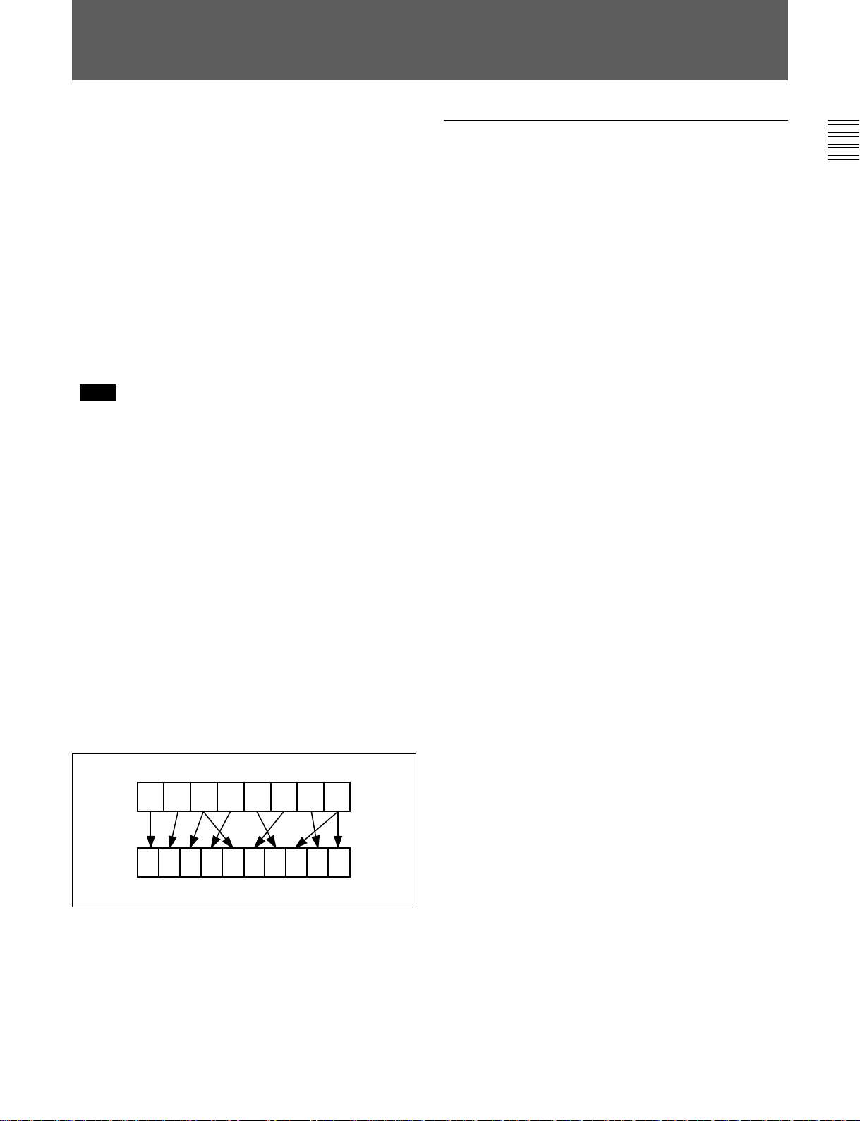
HKDV-507 HD Pull Down Board
This board allows the output of 2-3 pull down HD
signal of 59.94i or 60i mode when this unit is operated
with the frame frequency of 23.98 or 24 Hz. The 2-3
pull down sequence is as follows.
A(f1)
A(f2) B(f1) B(f2) C(f1) C(f2) D(f1) D(f2)
A(f1) A(f2) B(f1) B(f2) B(f1) C(f2) C(f1) D(f2) D(f1)D(f2)
..........................................................................................................................................................................................................
1) SDTI (Serial Data Transport Interface)
SDTI is defined as SMPTE-305M.
Chapter 1 Overview 1-5
Page 12

Page 13
2-1 Control Panel
Chapter 2 Locations and Functions of Parts and Controls
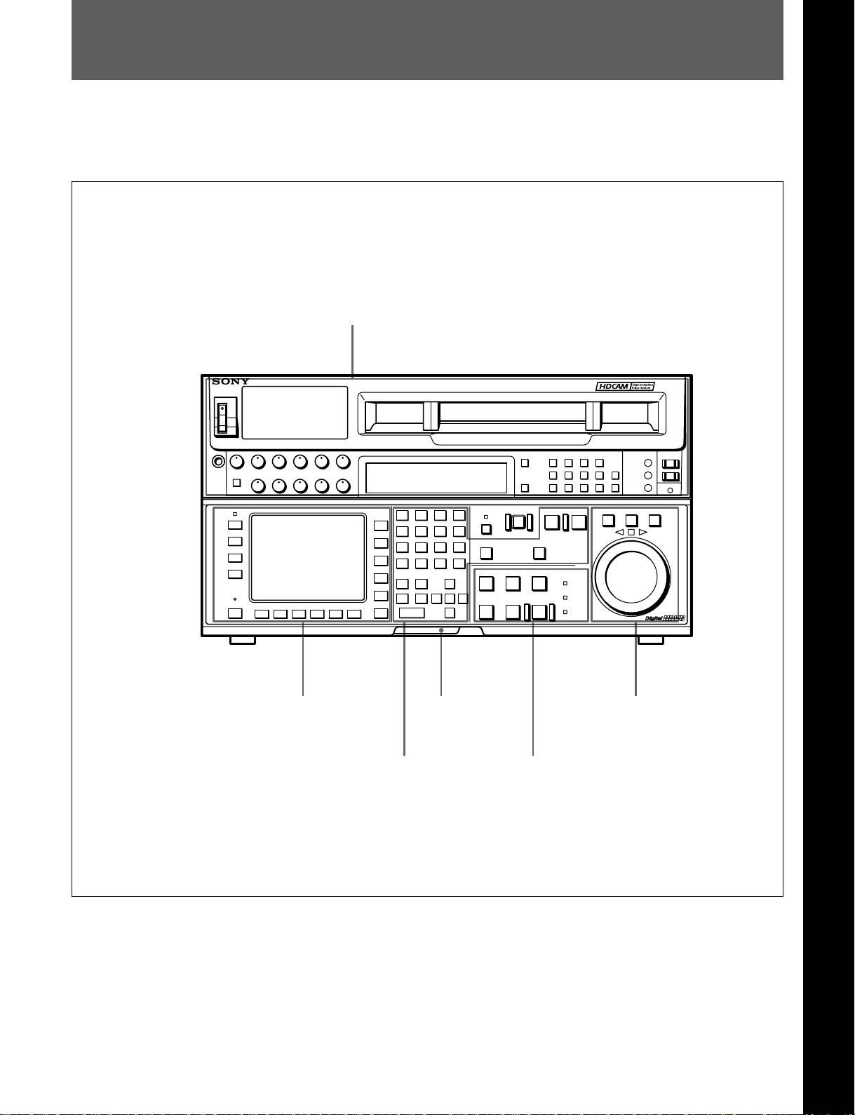
The control panel consists of the following sections:
•Upper control panel
•Lower control panel: menu operations section,
Upper control panel
Lower control panel
memory card insertion slot, editing operations
section, tape transport operations section and search
operations section
Chapter 2 Locations and Functions of Parts and Controls
DIGITAL VIDEO CASSETTE RECORDER HDW-F500
Menu operations section
Editing operations section
Memory card
insertion slot
Control panel
Search operations section
Tape transport operations section
Chapter 2 Locations and Functions of Parts and Controls 2-1
Page 14
2-1 Control Panel
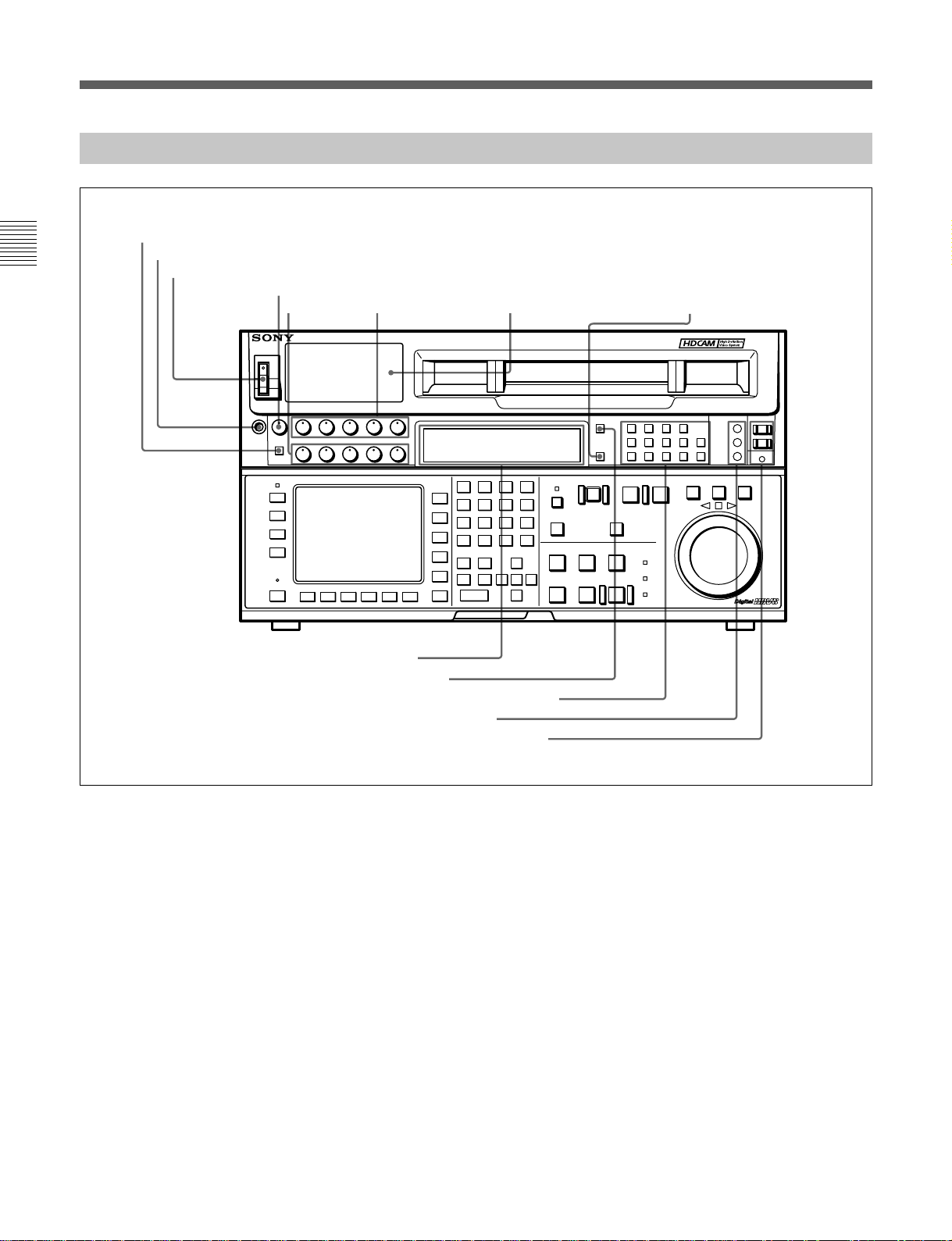
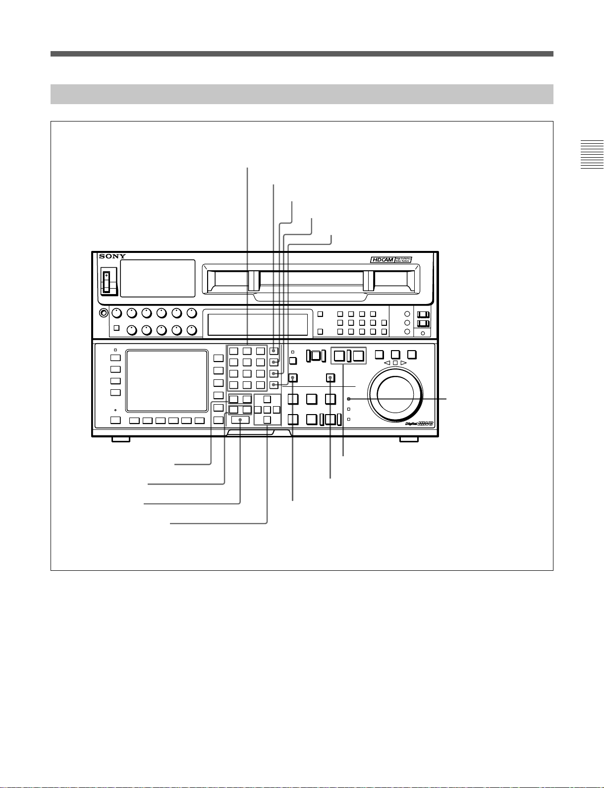
2-1-1 Upper Control Panel
1DISPLAY FULL/FINE button
2PHONES jack
Chapter 2 Locations and Functions of Parts and Controls
3POWER switch
4PHONES level control
5 PB level
controls
6REC level controls 7Audio level meters
DIGITAL VIDEO CASSETTE RECORDER HDW-F500
8MONITOR SELECT button
9Indicator window
!ºINPUT SELECT button
!¡AUDIO INPUT/MONITOR SELECT buttons
!™REFERENCE signal indicators
!£REMOTE buttons and RS-232C indicator
Upper control panel
1 DISPLAY FULL/FINE button
Changes the display range of the audio level meters.
FULL: Display range is –60 to 0 dB (peak level = 0
dB) or –40 to +20 dB (peak level = +20 dB).
Use 814. LEVEL METER SCALE in the VTR
SETUP menu to select the range.
FINE: Displays the audio level in 0.25 dB
increments. The center LED lights up in each
meter as a signal level reference. When the level
exceeds the maximum display value, the top LED
flashes. When the level falls below the minimum
display value, the bottom LED flashes.
2 PHONES jack
Connects stereo headphones with 8 Ω impedance for
audio monitoring during recording, playback, and
editing. Adjust the headphone output level with the
PHONES level control.
3 POWER switch
Turns on the power. When the power is turned on, the
audio level meters and menu display in the lower
control panel light up.
2-2 Chapter 2 Locations and Functions of Parts and Controls
Page 15

4 PHONES level control
Adjusts the output level to the PHONES jack.
You can enable this control to simultaneously adjust
the output level to the MONITOR OUTPUT
connectors on the connector panel.
For details, see Section 5-1-2, “Selecting Audio Signals” on
page 5-2.
5 PB (playback) level controls
Adjust the level of the audio output for channels 1 to 4
and the cue channel.
Pull out the controls during playback to adjust the
audio output for each channel. Push in again for
factory-set levels (+4 dB output for a signal recorded
at a reference level of 0 dB). When pushed in, the
controls cannot adjust the audio output level.
6 REC (recording) level controls
Adjust the recording level for channels 1 to 4 and the
cue channel.
Pull out the controls to adjust the recording level for
each channel in E-E mode
1)
. Push in again for the
factory-set recording level (0 dB reference level for an
input of +4 dB). When pushed in, the controls cannot
adjust the recording level.
9 Indicator window
The following indicators light up to indicate the VTR’s
status.
Indicators and corresponding VTR status
Indicator Status
CHANNEL
CONDITION
INTERLACE Lights when the VTR is operating under
PsF Lights when the VTR is operating under
23.98 Lights when the VTR is operating with a
24 Lights when the VTR is operating with a
25 Lights when the VTR is operating with a
29.97 Lights when the VTR is operating with a
30 Lights when the VTR is operating with a
Indicates the playback signal condition.
Green: Playback signal is good.
Yellow: Playback signal is less than
good, but still reproducible.
Red: Playback signal is poor. Head
cleaning or internal inspection is
necessary if the indicator lights up
continuously.
the interlace mode(50i/59.94i/60i).
the PsF mode(23.98PsF/24PsF/25PsF/
29.97PsF/30PsF).
frame frequency of 23.98 Hz.
frame frequency of 24 Hz.
frame frequency of 25 Hz.
frame frequency of 29.97 Hz.
frame frequency of 30 Hz.
Chapter 2 Locations and Functions of Parts and Controls
7 Audio level meters
For more information about the selection of the frame
frequency , refer to the supplied Maintenance Manual.
Indicate the recording level in recording or E-E mode
or the playback level in playback or CONFI mode.
The display range can be changed by pressing the
DISPLAY FULL/FINE button. The reference level is
factory set at –20 dB, and the peak level at 0 dB.
8 MONITOR SELECT button
Selects the audio signal to be output at the MONITOR
OUTPUT L/R connector(s). Press to light the button
up, then press the AUDIO INPUT/MONITOR
SELECT button(s) to specify which channel(s) are to
be monitored at the MONITOR OUTPUT L or R
connector. If you specify more than one channel to the
same MONITOR OUTPUT connector, a mixed audio
signal is output from that connector. This specification
can also be done with setting the VTR SETUP menu
807~808 AUDIO MONITOR L~R select .
For details, see Section 4-6-3, “Selecting the Monitor
Output Signal (MON-L SEL/MON-R SEL)” on page 4-43.
..........................................................................................................................................................................................................
1) E-E mode
An abbreviation for Electric-to-Electric mode. In this
mode, video or audio input signals are passed and output
only through the VTR’s internal circuitry, and not
through the magnetic conversion system comprising tape
and heads.
Chapter 2 Locations and Functions of Parts and Controls 2-3
Page 16

2-1 Control Panel
!º INPUT SELECT button
Selects the type and channel for the audio input signal.
Press to light the button up, then press one of the
AUDIO INPUT/MONITOR SELECT buttons to select
the type and the channel of the audio signal.
HD SDI (CH-1 to CH-4): Selects the input signal
Chapter 2 Locations and Functions of Parts and Controls
from the HD SDI INPUT or SDTI (OPTION) IN
connector.
AES/EBU (CH-1 to CH-4): Selects signal input to
the AUDIO INPUT (AES/EBU) connectors.
ANALOG (CH-1 to CH-4): Selects signal input to
the AUDIO INPUT connectors.
The INPUT SELECT button will flash if there is no
incoming signal and HD SDI or AES/EBU is selected.
This setting can also be done with setting the VTR
SETUP menu 802~805 AUDIO INPUT select
CH1~CH4.
Notes
•When the signal input to the SDTI (OPTION) IN
connector is selected for the input video signal, the
signal input to the SDTI (OPTION) IN connector is
automatically selected for the input audio signal as
well.
•When the audio signal input to the SDTI (OPTION)
IN connector is selected for the input audio signal,
only the INPUT SELECT button lights.
For details, refer to “4-6-1 Selecting the Audio Input
Signal” on page 4-43.
!¡ AUDIO INPUT/MONITOR SELECT buttons
Select the audio input signal when the INPUT
SELECT button is lit, or the audio signal to be
monitored when the MONITOR SELECT button is lit.
!™ REF SYNC (reference signal) indicators
These indicate the signal selected as the reference
signal. If there is no reference signal input to the
selected connector, the STOP button flashes.
EXT SD: Is lit when the video signal input to the
REF. IN SD connector is acting as the reference
signal.
EXT HD: Is lit when the video signal input to the
REF. IN HD connector is acting as the reference
signal.
INPUT VIDEO: Is lit when the video signal input to
the HD SDI INPUT or SDTI (OPTION) IN
connector is acting as the reference signal.
!£ REMOTE buttons and RS-232C indicator
Press these buttons to select external equipment to be
used to remotely control the VTR.
1(9 pin): Press to select the unit connected to the
REMOTE1-IN(9P)/OUT (9P) connectors. The
button lights up.
2(50 pin): Press to select the unit connected to the
PARALLEL I/O (50P) connector (with optional
BKDW-509). The button lights up.
RS-232C indicator: Lights up when the VTR is
communicating with the external equipment
connected to the RS-232C connector.
Note
When the VTR is being controlled by external
equipment connected to the REMOTE1-IN (9P) or
PARALLEL I/O (50P) connector, all tape transport
buttons and edit operation buttons are disabled, except
the STOP and EJECT buttons. You may also specify
the disabling or enabling of all buttons by setting
008.LOCAL FUNCTION ENABLE in the VTR
SETUP menu.
2-4 Chapter 2 Locations and Functions of Parts and Controls
Page 17
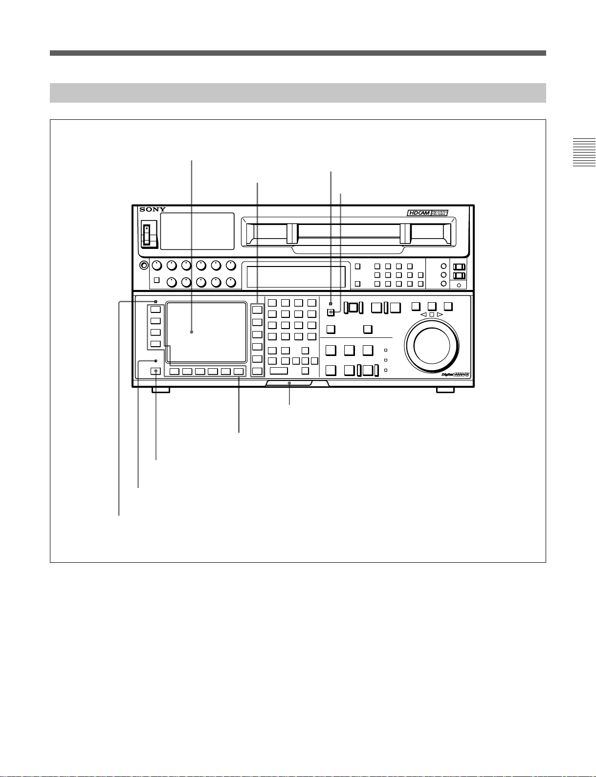
2-1-2 Lower Control Panel (Menu Operations Section)
1Menu display
3MEMORY CARD indicator
2Menu buttons
4ACCESS button
DIGITAL VIDEO CASSETTE RECORDER HDW-F500
Chapter 2 Locations and Functions of Parts and Controls
7ALT button
8MAINTENANCE switch
9ALARM indicator
5Memory card insertion slot
6Function buttons
Lower control panel (menu operations section)
Chapter 2 Locations and Functions of Parts and Controls 2-5
Page 18

2-1 Control Panel
1 Menu display
Menus selected by pressing the menu buttons appear
here.
Each menu shows the functions assigned to each
function button ([F1] to [F10]) and information
necessary for making settings, such as time codes.
Chapter 2 Locations and Functions of Parts and Controls
2 Menu buttons
Press to activate the respective menu.
HOME button: Activates the HOME menu.
Settings for basic or editing operations are made
in the HOME menu.
TC button: Activates the TC (time code) menu. In
the TC menu, you can switch between LTC and
VITC and between DF and NDF, and make
settings for time code displays on an external
monitor.
CUE button: Activates the CUE menu. In the CUE
menu, you can register 10 cue points per page for
a total of 100 cue points.
PF1 button: Activates the PF (Personal Function) 1
menu. In the PF1 menu, you can register
frequently used settings in other menus. Settings
for video input/output signals are factory set.
PF2 button: Activates the PF (Personal Function) 2
menu. In the PF2 menu, you can register
frequently used settings in other menus. Settings
for audio input/output signals are factory set.
SET UP button: Activates the SET UP menu. Use
the SET UP menu to restore settings to the VTR
memory banks or IC memory card, register
functions to the PF1/2 menus, and set items in the
VTR SETUP menu.
5 Memory card insertion slot
Insert memory cards here. VTR settings can be stored
on cards and used to configure the VTR and control
panel at a later date, thus reducing the time required
for set up.
Press the button beside the insertion slot to eject the
memory card.
6 Function buttons
Activates the functions in each menu.
7 ALT (alternative) button
Press to change the functions of the current menu.
Press again to return to the original functions.
8 MAINTENANCE switch
Activates the MAINTENANCE menu.
To operate this switch, push it in using the tip of a pen
or some other pointed object while holding down the
SFT button.
9 ALARM indicator
Flashes when the communication between the VTR
and the control panel is abnormal.
For details, see Chapter 4, “Menu Settings” on page 4-1.
3 MEMORY CARD indicator
Lights up when the memory card is inserted.
The indicator will flash when the memory card is
improperly inserted or when the memory card battery
is dead.
4 ACCESS button
Press this button to directly activate the MEMORY
CARD menu. Flashes when the control panel is
accessing the memory card.
Note
Do not eject the memory card while the ACCESS
button is flashing as this may damage the contents of
the memory card.
2-6 Chapter 2 Locations and Functions of Parts and Controls
Page 19
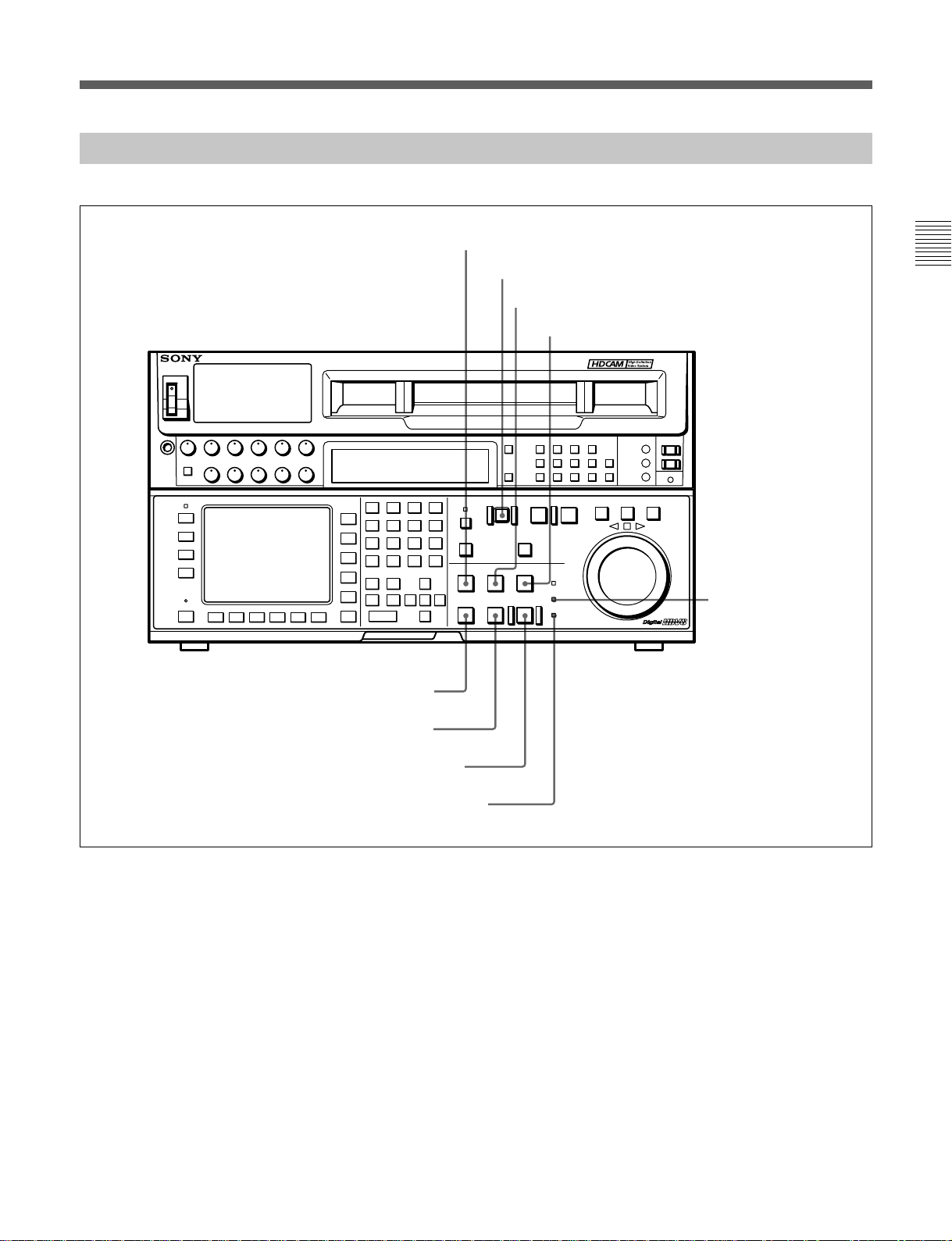
2-1-3 Lower Control Panel (Editing Operations Section)
!ºNumeric buttons and +/– buttons
!¡SFT button
!™RCL button
!£CLR button
!¢SET button
DIGITAL VIDEO CASSETTE RECORDER HDW-F500
Chapter 2 Locations and Functions of Parts and Controls
!∞AUDIO IN/OUT buttons
!§IN/OUT buttons
!¶ENTRY button
!•Cursor control buttons
@™PREREAD indicator
@¡PLAYER/RECORDER buttons
@ºINPUT CHECK button
!ªAUTO button
Lower control panel (editing operations section)
Chapter 2 Locations and Functions of Parts and Controls 2-7
Page 20

2-1 Control Panel
!º Numeric buttons and +/– buttons
Press to input time data or edit points data at the cursor
position in menu display. Press buttons 0 to 5 while
holding down the SFT button to input A to F
(hexadecimal figures) for user bits. Use the +/–
buttons to increase or decrease settings.
Chapter 2 Locations and Functions of Parts and Controls
!¡ SFT (shift) button
Press buttons 0 to 5 while holding down this button to
input A to F (hexadecimal figures) for user bits.
Use also in combination with other buttons to perform
other operations.
!™ RCL (recall) button
Press to call up a previously entered value.
!£ CLR (clear) button
Press to clear input data.
!¢ SET button
Press to finalize data.
!∞ AUDIO IN/OUT buttons
Press to set AUDIO IN and OUT points during insert
mode. Press either AUDIO IN or OUT button while
holding down the ENTRY button to set an audio edit
point.
!§ IN/OUT buttons
Press to set an IN or OUT point during editing. Press
either button while holding down the ENTRY button
to set an edit point.
!¶ ENTRY button
Press to enter an edit or cue point.
While holding down this button, press either the
AUDIO IN or OUT button, or the IN or OUT button.
!• Cursor control buttons
Press to move the cursor in the menu display. Move
the cursor as required to enter a value using the
numeric buttons, or to change a menu setting.
!ª AUTO button
When this button is pressed, it lights up and auto edit
mode is activated.
@º INPUT CHECK button
While you hold down this button, the input signal is
output from the monitor output connector, so that you
can monitor the input video and audio.
When the LTC/VITC time code is shown on the
display, you can check the time code generator.
Note
When the optional HKDV-501A HD-SD Converter
Board is installed in the unit and VTR SETUP menu
item 776 DOWNCONVERTER INPUT CHECK
ENABLE is set to “enable”, you can monitor
downconverter output. When you press the INPUT
CHECK button, the input video and audio is output
from all HD-SD converter output connectors.
@¡ PLAYER/RECORDER buttons
Select which VTR is to be controlled by this VTR’s
control panel during editing when this VTR is used as
a recorder and an external VTR is connected to the
REMOTE1-IN(9P)/OUT(9P) connectors as a player.
PLAYER: The tape transport buttons and editing
operation buttons on the control panel control the
external player VTR.
RECORDER: The tape transport buttons and
editing operation buttons on the control panel
control the recorder VTR (this VTR).
The PLAYER/RECORDER buttons have no effect
when using this VTR alone.
@™ PREREAD indicator
Lights up during preread mode.
For more information about PREREAD, see “6-2-3
Performing Preread Editing” on page 6-18.
2-8 Chapter 2 Locations and Functions of Parts and Controls
Page 21
2-1-4 Lower Control Panel (Tape Transport Operations Section)
@£STANDBY button
@•STOP button
@¢EJECT button
@∞PREROLL button
@§PREVIEW/REVIEW button
DIGITAL VIDEO CASSETTE RECORDER HDW-F500
Chapter 2 Locations and Functions of Parts and Controls
@¶SERVO indicator
@ªPLAY button
#ºREC/EDIT button
#¡REC INHIBIT indicator
Lower control panel (tape transport operations section)
@£ STANDBY button
Press this button in other than standby mode to make
it light up and place the VTR in standby mode. The
head drum rotates in standby mode, thereby
shortening the time required for the tape to start.
Press this button while in standby mode to turn the
button off and cancel standby mode. The head drum
stops rotating and the tape tension is released. If the
VTR remains in standby mode for more than eight
minutes (factory setting), standby mode is
automatically canceled in order to safeguard the tape.
@¢ EJECT button
Press to eject the cassette. When the button is pressed,
the tape is automatically unthreaded and the cassette is
ejected in a few seconds. Resets the display when CTL
codes appear in the menu display in the lower control
panel.
Chapter 2 Locations and Functions of Parts and Controls 2-9
Page 22

2-1 Control Panel
@∞ PREROLL button
Press to position the tape to the preroll point (a
position factory set to five seconds before the IN
point).
Press this button while holding down the IN, OUT,
AUDIO IN or AUDIO OUT button to cue up the tape
Chapter 2 Locations and Functions of Parts and Controls
at the edit point of the respective button.
For details on changing the preroll time, refer to “4-2-7
Setting the Preroll Time (PREROLL TIME)” on page 4-18.
@§ PREVIEW/REVIEW button
After edit points are set, press this button to preview,
on the monitor connected to the recorder, the effect of
the edit before it is performed. In this operation, the
tape runs, but no editing is carried out.
If you press this button after carrying out an edit, the
results of the edit are played back on the monitor
connected to the recorder.
@¶ SERVO indicator
Lights up when the drum servo and capstan servo are
locked.
@• STOP button
When you insert the cassette, the VTR automatically
enters stop mode.
The STOP button flashes when the [F2] (SERVO REF)
button in the PF1 menu is set to input but there is no
video input signal, when the [F2] (SERVO REF)
button in the PF1 menu is set to ext but there is no
external reference video signal, or when the input
signal is out of sync with the external reference video
signal. If you want, you can set 102. REFERENCE
SYSTEM ALARM in the VTR SETUP menu so that
the STOP button will not flash under the above
conditions.
@ª PLAY button
Starts playback.
Press this button while holding down the REC button
to start recording.
Pressing this button during recording or manual editing
changes the VTR to playback mode.
#º REC/EDIT (recording/edit) button
Press this button while holding down the PLAY button
to start recording.
If you press this button in play mode manual editing
begins. After setting edit points, if you press this
button while the AUTO button is lit, automatic editing
is performed.
#¡ REC INHIBIT indicator
The status of this indicator depends on the setting of
the ALT button and [F2] (REC INH) button in the
HOME menu and the state of the record-protect plug
on the cassette.
Status of the REC INHIBIT indicator
Setting of the ALT
and [F2] (REC INH)
buttons in the
HOME menu
all Recording disabled Lit/flashing
crash REC, video/
CTL, audio/CTL
off Recording disabled Lit/flashing
a) Toggle between lit/flashing settings is possible using the
104.REC INHIBIT LAMP FLASHING setting in the
VTR SETUP menu.
State of the recordprotect plug on the
cassette
Recording allowed Lit
Recording disabled Lit/flashing
Recording allowed Unlit
REC INHIBIT
indicator
UnlitRecording allowed
a)
a)
a)
a)
Recording, editing, and selection of assemble and
insert modes are possible only when the indicator is
off.
2-10 Chapter 2 Locations and Functions of Parts and Controls
Page 23
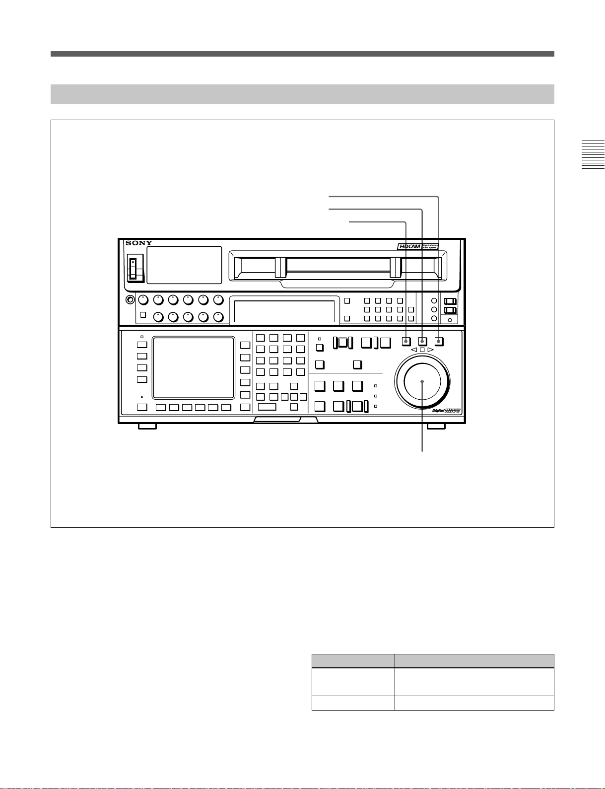
2-1-5 Lower Control Panel (Search Operations Section)
#™ VAR button
#£ JOG button
#¢ SHUTTLE button
DIGITAL VIDEO CASSETTE RECORDER HDW-F500
Chapter 2 Locations and Functions of Parts and Controls
Lower control panel (search operations section)
#™ VAR button
Press to select variable speed playback mode for
noiseless playback in a maximum range of –1 to +2
times normal playback speed, in 51 steps. Playback
exceeding this speed range is not possible. The search
dial clicks at the positions for still-picture and normal
playback speed.
#£ JOG button
Press to select jog mode. In this mode, the button
lights up and playback at –1 to +1 or –2 to +2 times
normal playback speed is possible (determined by the
107. JOG DIAL RESPONSE setting in the VTR
SETUP menu). In this mode, the search dial does not
click.
#∞ Search dial
#¢ SHUTTLE button
Press to enter shuttle mode. In this mode, the button
lights and playback corresponding to the angle of
rotation of the search dial. The playback speed is
different depending on the frame frequency of the unit.
In this mode, the search dial clicks at the positions for
0 (still-picture), –10 and +10 times normal playback
speed.
Frame frequency Playback speed
23.98/24 Hz Ranging from –60 to +60
25 Hz Ranging from –58 to +58
29.97/30 Hz Ranging from –50 to +50
Chapter 2 Locations and Functions of Parts and Controls 2-11
Page 24

2-1 Control Panel
#∞ Search dial
Rotate to search for edit points. Rotate the dial
clockwise for forward playback (the z indicator lights
up) or counterclockwise for reverse playback (the Z
indicator lights up). The p indicator lights up while
the VTR is in stop mode.
Chapter 2 Locations and Functions of Parts and Controls
Shuttle mode: The playback speed is different
depending on the frame frequency of the unit. (See
item #¢SHUTTLE button.) The dial clicks at the
positions corresponding to 0 (still-picture), –10
and +10 times normal playback speed.
Jog mode: The playback speed corresponds to the
rotational speed of the dial (–1 to +1 or –2 to +2
times normal playback speed depending on the
107.JOG DIAL RESPONSE setting in the VTR
SETUP menu). The dial does not click.
Variable speed playback mode: Noiseless playback
at –1 times normal speed when the dial is rotated
fully counterclockwise, and +2 times normal
speed when rotated clockwise. The dial clicks at
the positions of still-picture and normal playback
speed.
Capstan override mode: Rotating the dial while
holding down the PLAY button changes the
playback speed by up to ±15%.
After turning the power on, always set the search dial
at the center position (where the p indicator lights up).
2-12 Chapter 2 Locations and Functions of Parts and Controls
Page 25
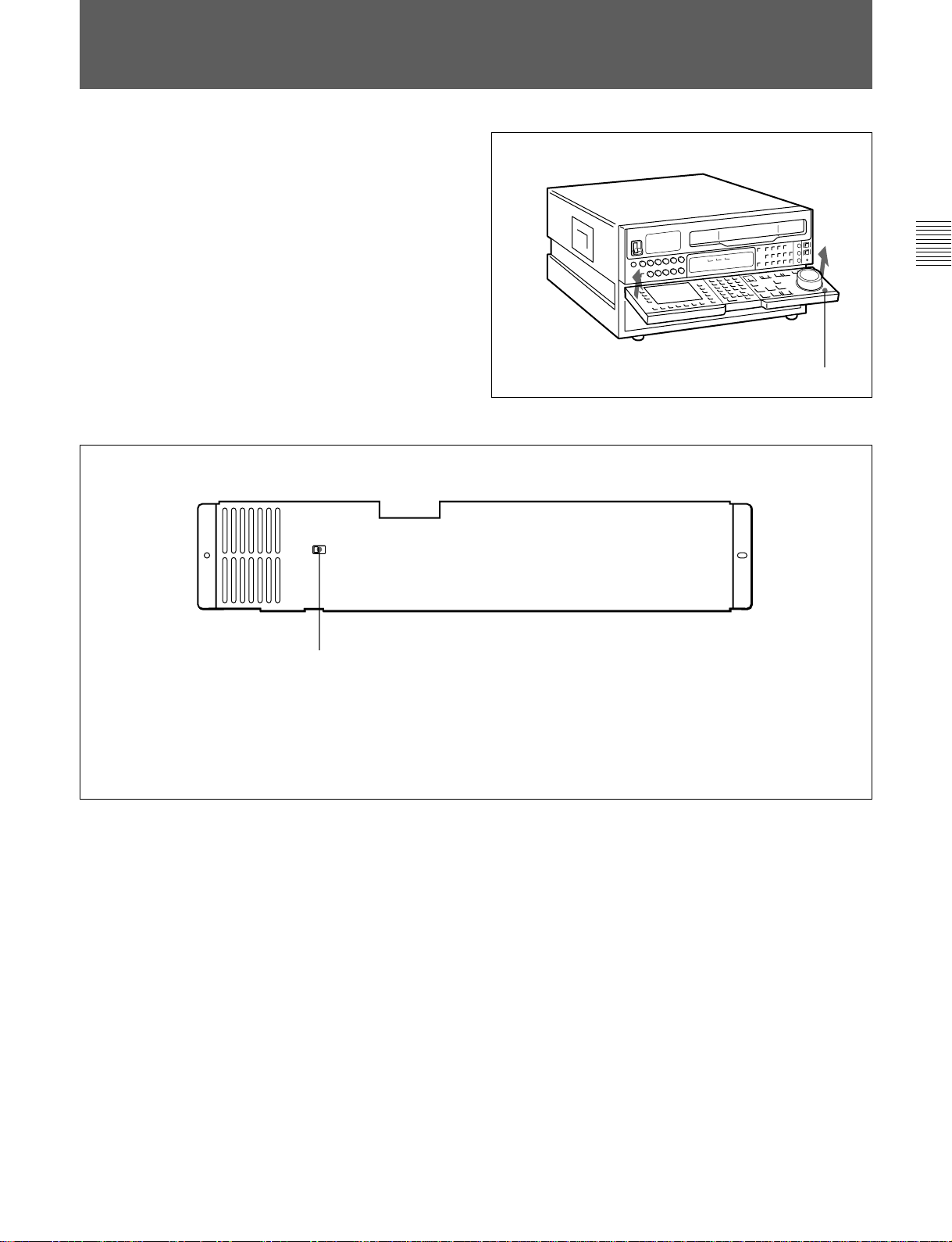
2-2 System Set-Up Panel
Lift the lower control panel up to its horizontal
position to access the system set-up panel.
Chapter 2 Locations and Functions of Parts and Controls
Lower control panel
Accessing the system set-up panel
CONTROL PANEL
EXT
INT
CONTROL PANEL switch
Selects which control panel controls this VTR.
INT: Control is by the control panel attached to
this VTR.
EXT: Control is remote, by connection to the
CONTROL PANEL connector on the rear
panel.
The switch is factory-set to INT.
System set-up panel
Chapter 2 Locations and Functions of Parts and Controls 2-13
Page 26
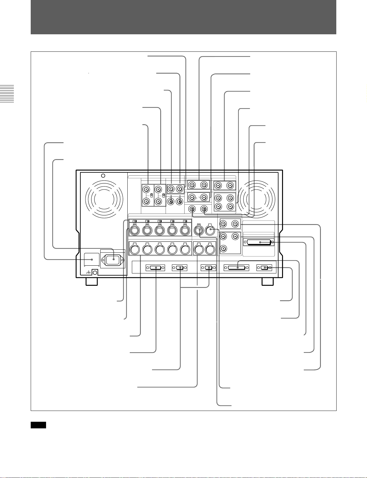
2-3 Connector Panel
2-3 Connector Panel
1 REF. OUT 1125 SYNC connectors
2 D CONV. OUT (OPTION) COMPOSITE
(SUPER) connector
3 D CONV. OUT (OPTION) SYNC connector
Chapter 2 Locations and Functions of Parts and Controls
4 REF. IN SD connectors and 75 Ω
termination switch
5 REF. IN HD connectors and 75 Ω
termination switch
6 BREAKER button
7 ⁄AC IN connector and
ground connector
8 AUDIO INPUT (AES/EBU)
connectors
9 AUDIO OUTPUT (AES/EBU)
connectors
!º HD SDI INPUT connectors
!¡ HD SDI OUTPUT connectors
!™ SDTI (OPTION) IN connector
!£ SDTI (OPTION) OUT
connector
!¢ AUDIO INPUT LEVEL/
600Ω termination switches
!∞ AUDIO INPUT connectors
!§ AUDIO OUTPUT connectors
!¶ CONTROL PANEL connector
!• REMOTE1-IN(9P)/OUT(9P) connectors
!ª MONITOR OUTPUT connectors
Connector panel
Note
For the AUDIO INPUT CH1/2/3/4 CUE connectors,
AUDIO OUTPUT CH1/2/3/4/CUE connectors, as well
as the TIME CODE IN/OUT (XLR, 3 pins)
2-14 Chapter 2 Locations and Functions of Parts and Controls
@º VIDEO CONTROL
connector
@¡ RS-232C connector
@™ PARALLEL I/O (50P) connector
@£ D CONV. SDI OUT (OPTION)
connectors
@¢ PULL DOWN OUT (OPTION)
connector
@∞ TIME CODE OUT connector
@§ TIME CODE IN connector
connectors, the type (male or female) of input/output
connectors used overseas are opposite of those used in
Japan. To use this unit with audio equipment outside
of Japan, you must use male/female adapters.
Page 27

1 REF. OUT 1125 SYNC connectors (BNC)
Outputs a trilevel sync signal for the external
synchronization. The field frequency is synchronized
to the input video signal.
2 D CONV. OUT (OPTION) COMPOSITE
(SUPER) connector (BNC)
Outputs an analog composite signal for a video
monitor. When the ALT/[F6] (CHARA SUPER)
setting in the TC menu is on, character signals such as
time codes are superimposed on the output.
Note
This connector is operative only when the optional
HKDV-501A HD-SD Converter Board is installed.
3 D CONV. OUT (OPTION) SYNC connector
(BNC)
Outputs an NTSC external sync signal.
6 BREAKER button
Primary circuit breaker for the AC power circuit.
7 ⁄AC IN connector and connector
Connects to an AC outlet using the power cord
supplied with the VTR.
8 AUDIO INPUT (AES/EBU) connectors (BNC)
Inputs for digital signals in AES/EBU format for
channels 1 to 4.
9 AUDIO OUTPUT (AES/EBU)connectors (BNC)
Outputs digital signals in AES/EBU format for
channels 1 through 4.
!º HD SDI (SDI video/audio) INPUT connectors
(BNC)
The left connector accepts HD SDI video/audio
signals.
Chapter 2 Locations and Functions of Parts and Controls
Notes
•This is effective only when the optional HKDV-501A
HD-SD Converter Board is installed.
•The phase is the same as the phase of the composite
signal output from the COMPOSITE (SUPER) of D
CONV. OUT (OPTION) connector. Because the
output phase changes with the operation mode of the
VTR, use this to synchronize with the video monitor.
4 REF. IN SD connectors (BNC) and 75 Ω
termination switch
Inputs for a reference video signal (NTSC or PAL) of
the selected field frequency. Use a video signal with
chroma burst (VBS) or a monochrome video signal
(VS).
A loop-through connection is possible. Set the 75 Ω
termination switch to OFF if you are using a loopthrough connection and set it to ON if you are not
using a loop-through connection.
5 REF. IN HD connectors (BNC) and 75 Ω
termination switch
Inputs for a reference video signal (HD) of the selected
field frequency. Use a trilevel SYNC signal for the
external synchronization. A loop-through connection
is possible. Set the 75 Ω termination switch to OFF if
you are using a loop-through connection and set it to
ON if you are not using a loop-through connection.
Note
The INPUT MONITOR connector is for use with an
input monitor and does not follow the standards for
output.
!¡ HD SDI (SDI video/audio) OUTPUT connectors
(BNC)
Outputs up to four (1 to 4) HD SDI video/audio signal
lines.
Character data such as time codes are superimposed on
the signal from the MONITOR connector when the
ALT/[F6] (CHARA SUPER) setting in the TC menu is
set.
!™ SDTI (OPTION) IN connector (BNC)
Outputs a video/audio SDTI signal.
Note
This connector is operative only when the optional
HKDV-506A SDTI Board is installed.
!£ SDTI (OPTION) OUT connector (BNC)
Inputs a video/audio SDTI signal.
Note
This connector is operative only when the optional
HKDV-506A SDTI Board is installed.
Chapter 2 Locations and Functions of Parts and Controls 2-15
Page 28

2-3 Connector Panel
!¢ AUDIO INPUT LEVEL/600Ω termination
switches
The termination switches should be set for in
ANALOG AUDIO INPUT connector according to the
audio input level and input impedance.
Use OFF for low input levels when:
Chapter 2 Locations and Functions of Parts and Controls
Audio input level is –60 dBu (microphone input)
and audio input impedance is high (approximately
20 kΩ)
Use OFF for high input levels when:
Audio input level is +4 dBu (line input) and audio
input impedance is high (approximately 20 kΩ)
Use ON for high input levels when:
Audio input level is +4 dBm (line input) and audio
input impedance is 600Ω
!∞ ANALOG AUDIO INPUT connectors
(XLR-3-32)
Accepts up to five analog audio signal lines (channels
1 to 4 and cue).
!§ ANALOG AUDIO OUTPUT connectors
(XLR-3-31)
Outputs up to five analog audio signal lines (channels
1 to 4 and cue).
!¶ CONTROL PANEL connector (15-pin)
Connects the control panel through the 15-pin cable
when using the control panel is used as a remote
controller.
!• REMOTE1-IN (9P)/OUT (9P) connectors
(D-sub 9-pin)
Used with the included 9pin remote control cable to
connect two HDW-F500 VTRs, or a second HD VTR
when a BVE900/910/2000/9000/9100 series BVE
Editing Control Unit is used for editing. Used when
you edit using two VTRs and the BVE-900/910/2000/
9000/9100 Editing Control Unit. The REMOTE1-IN
and OUT connectors can be used to make a bridge
connection.
!ª MONITOR OUTPUT connectors (XLR-3-31)
Outputs signals for audio monitoring. These
connectors output two signal lines: L and R. Select
the signals to be output with the MONITOR SELECT
buttons and the AUDIO INPUT/MONITOR SELECT
buttons on the upper control panel. A setting can be
made so that volume can be controlled with the
PHONES volume knob.
For details, see Section 5-1-2, “Selecting Audio Signals”on
page 5-2.
@º VIDEO CONTROL (Digital Video Processor
Control) connector (D-sub 9-pin)
Connects to the optional HKDV-503 HD Digital Video
Controller to enable remote control of the internal
digital video processor. Turn off the power before
connecting the remote controller.
@¡ RS-232C connector (RS-232C serial interface)
(D-sub 25-pin)
Receives or transmits RS-232C serial remote control
signals and/or VTR status data from/to external
equipment. When this connector is being used for
communication, the RS-232C indicator on the upper
control panel will be lit.
@™ PARALLEL I/O (50P) connector (D-sub 50-pin,
with optional BKDW-509)
Inputs an external remote control signal.
For details, refer to the Maintenance Manual.
@£ D CONV. SDI (D1/D2 SDI video/audio)
(OPTION) OUT connectors (BNC)
Outputs up to three sets of video/audio signals. When
the ALT/[F8] (CHARA SUPER) key of the TC menu
is set to ON, text data such as time codes are
superimposed on the output of connector 3 (SUPER).
Selection of D1/D2 output is made using the [F9]
(OTHERS CHECK)/[F9] (SYSTEM)/[F3] (D-CONV
SDI) button in the MAINTENANCE menu.
Note
This connector is operative only when the optional
HKDV-501A HD-SD Converter Board is installed.
@¢ PULL DOWN OUT (OPTION) connectors
(BNC)
Outputs two sets of 2-3 pull down video/audio signals.
When the ALT/[F5] (PD CHARA) key of the TC
menu is set to ON, text data such as time codes are
superimposed.
Note
This connector is operative only when the optional
HKDV-507 HD PULL DOWN Board is installed.
2-16 Chapter 2 Locations and Functions of Parts and Controls
Page 29

@∞ TIME CODE OUT connector (XLR-3-31)
Outputs the following time codes according to the
VTR operation mode.
In playback mode: Playback time codes
In recording mode: Time codes generated by the
internal time code generator, or time codes input
to the TIME CODE IN connector.
To select the output signal for the TIME CODE OUT
connector, use the 613.TC OUTPUT SIGNAL IN
REGEN MODE setting in the VTR SETUP menu.
Setting Description
off tape In playback mode, playback time codes are
regene Playback time codes are regenerated and
through
selected, and in recording mode, TCH time
code signals are used.
output only in playback mode when the servo
is locked. In all other cases, output is the
same as for the “off tape” setting.
The time code signal from the TIME CODE
IN connector is output as is. (Used during
cascade connections.)
(For more information about cascade
connections, see 3-1-4 Cascade
Connections on page 3-4.)
Chapter 2 Locations and Functions of Parts and Controls
@§ TIME CODE IN connector (XLR-3-32)
Accepts external time codes for recording to tape.
Connect to the time code output connector of the
external equipment.
Chapter 2 Locations and Functions of Parts and Controls 2-17
Page 30

Page 31

3-1 Connecting External Equipment
3-1-1 Making Digital Connections
Chapter 3 Setting Up the VTR
This example shows how to connect the HDD/HDDP1000 1 inch HD Digital VTR and use it as the player
REMOTE (9Pin)
DIGITAL AUDIO
CH-1/2
9 pin remote cable
HDD/HDDP-1000
with the HDW-F500 acting as the recorder in the
59.94i or 60i mode.
50 PIN PARALLEL
XLR/BNC
Converter
CH-3/4
DIGITAL VIDEO
OUTPUT
P/S Converter
HD SDI OUTPUT
Chapter 3 Setting Up the VTR
REMOTE 1-IN (9P)
Making digital connections
Refer to the “Specifications” section in the appendix (page
A-2) for recommended XLR/BNC and P/S converters.
HD SDI OUTPUT
Video monitor
(HD serial monitor)
Chapter 3 Setting Up the VTR 3-1
Page 32

3-1 Connecting External Equipment
3-1-2 Making HD Analog Connections
This example shows how to connect the VTR when
using HD analog audio and video signals in the 60i
mode.
Chapter 3 Setting Up the VTR
REMOTE (9P)
ANALOG AUDIO
OUTPUT CH-1 to 4
9-pin remote cable
HDV-10 1/2 inch VTR
or other player
ANALOG VIDEO
OUTPUT
HKPF-101 A/D
Converter
HD SDI OUTPUT
HD SDI OUTPUT
HKPF-102 D/A
Converter
3-2 Chapter 3 Setting Up the VTR
Set the analog audio input level and
impedance using the AUDIO INPUT
LEVEL/600Ω termination switches as
follows:
For line input with a 600Ω termination:
HIGH and ON
For high-impedance line input: HIGH
and OFF
For high-impedance microphone input:
LOW and OFF
ANALOG VIDEO
OUTPUTREMOTE 1-IN (9P)
Video monitor (HD
monitor)
Page 33
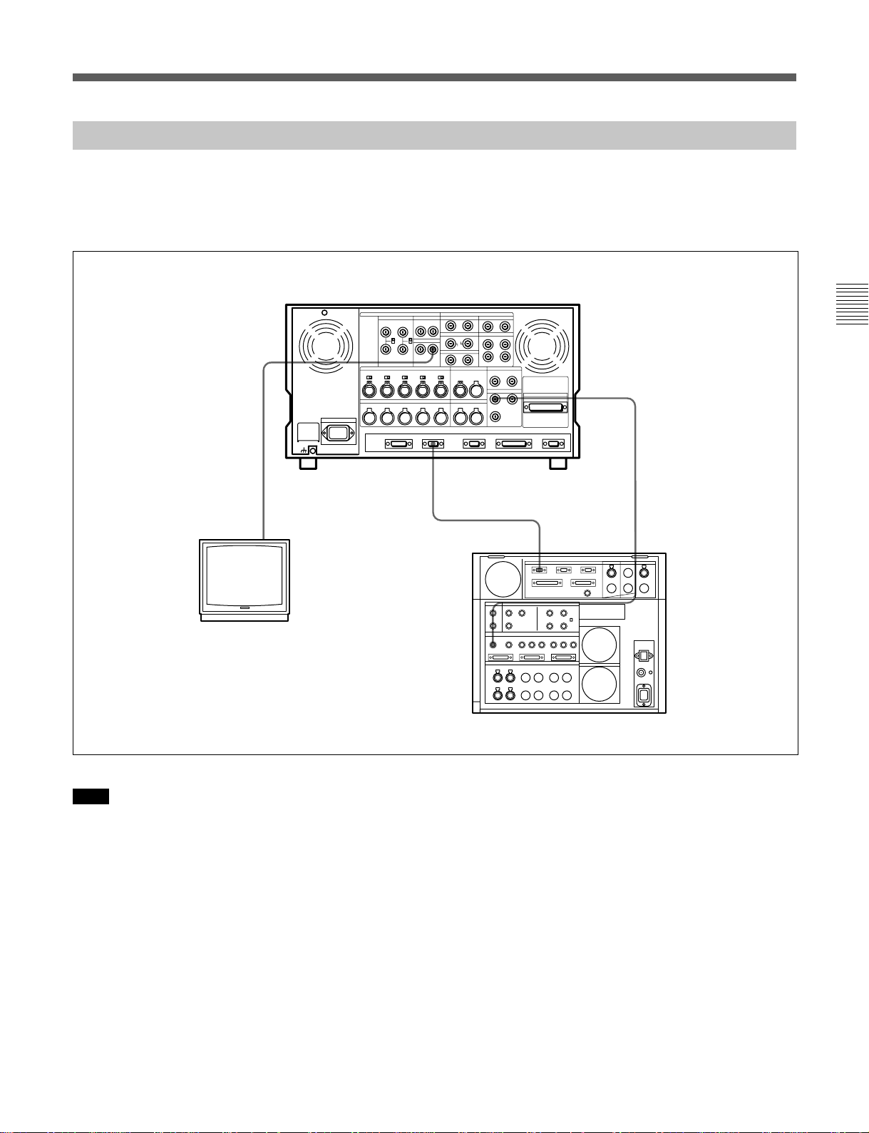
3-1-3 Making NTSC/PAL Digital Connections
This example shows how to connect two VTRs
together, using an HDW-F500 as the players and a
DVR-2100 D-1 Component Digital VTR as the
recorder.
HDW-F500 (Player)
[Input]
Chapter 3 Setting Up the VTR
REMOTE 1-IN
BNC cable
COMPOSITE
VIDEO OUTPUT
Video monitor
(NTSC/PAL monitor)
Note
For color frame editing using the HDW-F500 as the
player and an NTSC/PAL digital device as the
recorder, set 005.SERVO/AV REFERENCE select in
the VTR SETUP menu to external and set
006.EXTERNAL REFERENCE select to extern SD.
9 pin remote cable
REMOTE-1
[output]
D CONV. SDI OUT (OPTION)
(D1 SDI)
BNC cable
SDI INPUT
DVR-2100 (Recorder)
Chapter 3 Setting Up the VTR 3-3
Page 34

3-1 Connecting External Equipment
3-1-4 Cascade connection
This example shows how to connect multiple HDW-F500 VTRs together for simultaneous recording.
Chapter 3 Setting Up the VTR
HDW-F500 (Player)
HD SDI OUTPUT
TIME CODE OUT
BNC cable
HDW-F500 (Recorder)
HDW-F500 (Recorder)
TIME CODE IN
TIME CODE OUT
TIME CODE IN
HD SDI INPUT
HD SDI INPUT
Digital video
distributor
HKPF-103M
HD SDI OUTPUT
Video monitor(HD serial
monitor)
Note
On the recording VTRs, set 613.TC OUTPUT
3-4 Chapter 3 Setting Up the VTR
SIGNAL IN REGENE MODE in the VTR SETUP
menu to through.
Page 35

3-2 Reference Signals for Video Output and Servo System
This section describes how reference signals for the
video output and servo system are selected.
3-2-1
Reference Signals for Output Video
Depending on the operating condition, VTR SETUP
menu setting, and the input signal, the video output
signal from the VTR can be synchronized as follows.
Start
What is
ext
the 005.SERVO/AV
REFERENCE select setting
in the VTR SETUP
menu?
auto
Is the VTR currently
recording or is EDIT
PRESENT on?
input
Yes
Chapter 3 Setting Up the VTR
No
What is the 006.
EXTERNAL REFERENCE
select setting in the VTR
SETUP menu?
extrn HD
Is there a signal of the
correct frequency on the
REF. IN HD connector?
No
Synchronization
with the reference
video signal input
to the REF. IN HD
connector
extrn SD
Yes
No external synchronization (synchronization is internal)
Is there a signal of the
correct frequency on the
REF. IN SD connector?
No
Synchronization
with the video
signal input to the
REF. IN SD
connector
Yes
Is there an input
signal on the connector
selected by the 701.VIDEO
INPUT select setting
in the VTR
SETUP?
No
Synchronization
with the video
signal input
designated by the
701.VIDEO INPUT
select setting
Yes
Chapter 3 Setting Up the VTR 3-5
Page 36

3-2 Reference Signals for Video Output and Servo System
3-2-2 Reference Signals Connections
Make the reference signal connections as follows,
according to your recording or playback requirements.
Reference signal connections
For recording signals from a switcher or signal generator
Chapter 3 Setting Up the VTR
Reference signal
Switcher or signal generator
HD SDI INPUTREF. IN
For recording signals from a switcher or signal generator
For recording signals from a HD VTR
Reference signal
REF. IN
HDW-F500 (Recorder)
75Ω termination switch: OFF
HD SDI INPUT
75Ω termination switch: ON
HD SDI OUTPUT
HDW-F500 (Player)
75Ω termination switch: ON
3-6 Chapter 3 Setting Up the VTR
For recording signals from a HD VTR
Page 37

For playback
Reference signal
REF. IN
75Ω termination switch: ON
Note
The following signals can be used as a reference
signal.
•HD trilevel SYNC signal of an appropriate field
frequency for the external synchronization
•Black burst signal of 525/59.94 Hz
•Black burst signal of 625/50 Hz
Input the signal of the appropriate field frequency for
your system.
HD SDI OUTPUT
1/2/3/MONITOR
HD serial input monitor
Chapter 3 Setting Up the VTR
Chapter 3 Setting Up the VTR 3-7
Page 38

3-3 Handling Cassettes
3-3 Handling Cassettes
3-3-1 Recommended Cassettes
Use 1/2 inch HDcam cassettes.
The maximum recording time is as shown in the
following table.
HDcam
cassette
S-size cassette
Chapter 3 Setting Up the VTR
L-size cassette
Note
Digital Betacam cassettes cannot be used.
Storage of cassettes
Store your cassettes at room temperature and normal
humidity.
System
frequency
29.97/30 Hz 25 Hz 23.98/24 Hz
40 minutes 48 minutes 50 minutes
124 minutes 149 minutes 155 minutes
3-3-2 Inserting and Ejecting Cassettes
Always turn on the VTR before attempting to insert or
eject cassettes.
Inserting a cassette
1
2
S-size cassette
L-size cassette
Inserting a cassette
1 Turn the POWER switch to ON.
2 Before inserting a cassette, check the following
points:
•There is no slack in the tape.
•An error message does not appear in the menu
display.
•The window of the cassette is facing up.
If there is any slack in the tape, refer to “Removing
slack in the tape” on next page.
When inserting an S-size cassette, make sure it is
aligned with the marks on the cassette insertion
slot.
The cassette is loaded automatically, and the tape is
wound around the drum.
3-8 Chapter 3 Setting Up the VTR
Page 39
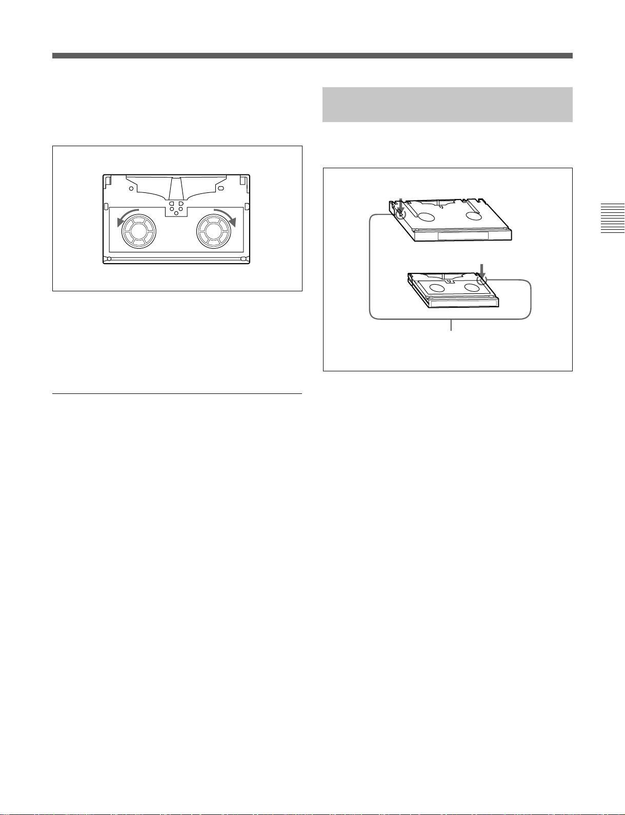
Removing slack in the tape
Press one of the reels in slightly, then carefully rotate it
in the direction of the arrow until it stops.
Removing slack in the tape
3-3-3 Preventing Accidental Erasure
To prevent accidental erasure of material recorded on a
tape, push in the record-protect plug.
L-size cassette
Chapter 3 Setting Up the VTR
S-size cassette
Preventing double cassette inserting
When a cassette is loaded, an orange lock-out bar
appears in the cassette insertion slot to prevent users
from attempting to load another cassette.
Ejecting the cassette
Press the EJECT button.
The tape is unthreaded and the cassette is
automatically ejected. This operation takes a few
seconds.
To cancel ejecting a cassette
Press any operation button before the cassette is
completely ejected. The cassette is loaded again and
the operation corresponding to the button you pressed
starts.
Push in the record-protect plug.
To restore the tape for recording, return the plug to its
original position.
Preventing accidental erasure
When a cassette with this plug pushed in is inserted
into the VTR, the REC INHIBIT indicator on the
lower control panel lights up and recording will not
start, even if you press the REC button.
To restore the tape for recording, return the plug to its
original position.
Chapter 3 Setting Up the VTR 3-9
Page 40

Page 41

4-1 Registering and Storing Menu Settings
Chapter 4 Menu Settings
The operating conditions of the VTR are set using the
menu operation section on the lower control panel.
Menu items are divided among six different menus
(HOME, TC, CUE, PF1, PF2, SET UP).
Of these menus, the PF1/PF2 (Personal Function)
menus can be used to register frequently used menu
items from the other menus, allowing faster setting of
VTR operating conditions. Eight VTR memory banks
are provided for storing up to eight sets of menu
settings. The contents of the eight VTR memory
banks can, in turn, be stored on a memory card for
later recall.
4-1-1 Menu Configuration
This VTR has two kinds of menus.
PF1&2 ASSIGN menu
This menu contains items that can be registered to the
PF1/2 menus.
Press the [F4] (PF1&2 ASSIGN) button in the SET UP
menu to display this menu.
For details on registering items in the PF1&2 ASSIGN
menu to the PF1/2 menus, see Section 4-1-3, “Registering
Items to the PF1/2 Menus” on page 4-3.
VTR SETUP menu
This menu contains items that specify the initial
operating conditions of the VTR. You can change
these settings directly without registering the items to
the PF1/2 menus.
Press the [F6] (VTR SETUP) button in the SET UP
menu to display this menu.
For details on setting operating conditions of the VTR, see
Section 4-7-1, “VTR SETUP Menu” on page 4-46.
Chapter 4 Menu Settings
The menu configuration of the VTR is shown in the
figure below,
HOME menu
TC menu
PF1 menu
PF2 menu
CUE menu
SETUP menu
[F4]
(PF1&2 ASSIGN) button
[F6] (VTR SETUP) button
Registration
Menu configuration
PF1&2
ASSIGN menu
VTR SETUP
menu
•All items in the HOME, TC, and CUE menus can be
duplicated and registered to the PF1/2 menus.
•Most items in the VTR SETUP menu can be
registered to the PF1/2 menus.
Chapter 4 Menu Settings 4-1
Page 42

4-1 Registering and Storing Menu Settings
To activate the HOME, TC, CUE, PF1, PF2, or SET
UP menu, press the respective menu button.
Menu items are assigned to function buttons ([F1] to
[F10]) in each menu. When two items are registered to
the same function button, you can display the second
item by pressing the ALT button.
The example below describes the procedure for
changing the setting specified by the ALT button and
[F5] (CAP LOCK) button in the HOME menu.
Chapter 4 Menu Settings
4-1-2 Changing Menu Settings
1
23
2 Press the ALT button.
The second page of the HOME menu appears in
the display.
PRE
READ
off
REMAIN-T
L 113min
CH.COND
PLÅY LOCK
TCR NDF 2FD F1
GREEN
ÅLT+HOME
01Ó 04µ 58ß 00ƒ
ÅIN 00:01:10:00 ÅOUT 00:02:10:00
IN 00:01:10:00 OUT 00:02:10:00
FREEZE
PRE-
CÅP
ROLL
LOCK
2FD
5sec off
DMC
STOP
CODE
LÅST
EDIT
To return to the first page
Press the ALT button again.
3 Press the [F5] (CAP LOCK) button to change the
capstan servo lock mode setting.
Each time the button is pressed, the setting
changes.
Changing menu settings
1 Press the HOME button.
The first page of the HOME menu appears in the
display.
INS
off
HOME
INS
Å-CH4
off
INS
CUE
off
REMAIN-T
PB/EE
L 113min
PLÅY LOCK
PB
TCR 2FD F1
RECINH
off
ÅIN 00:01:10:00 ÅOUT 00:02:10:00
ÅSSEM-
IN 00:01:10:00 OUT 00:02:10:00
BLE
off
INS
TC
off
INS
VIDEO
Å-CH1
off
CH.COND
GREEN
01Ó 04µ 58ß 00ƒ
INS
INS
Å-CH2
off
Å-CH3
off
Changing menu settings using the cursor
control buttons
You may also use the cursor control buttons to select
menu items and change menu settings by moving the
on-screen cursor.
For settings which cannot be made by the function
buttons alone, the following icons appear in the
bottom-right of the menu to indicate the use of the
cursor control buttons:
: All cursor control buttons
: Cursor control buttons for horizontal
direction
: Cursor control buttons for vertical direction
In addition to operations using the cursor control
buttons, some menus allow you to change a value by
using the [+]/[–] buttons.
4-2 Chapter 4 Menu Settings
Page 43

4-1-3 Registering Items to the PF1/2 Menus
You can register up to 40 items to the PF (Personal
Function) 1/2 menus, including items that are
displayed when the ALT button is pressed. The
registration of items from different menus to the PF1/2
menus eliminates the need for changing menus in
order to change a given VTR operating condition.
For details on the factory-set PF1/2 menus, see Section 4-5,
“PF1 Menu (Factory Settings)” on page 4-38 and 4-6,
“PF2 Menu (Factory Settings)”on page 4-42.
Current setting
Item currently
registered to the
button
REMAIN-T
PF1
L 113min
ÅLT+
F1KEY SETUP ITEM-755
PF1
1:701 755:MASTER(D1)
2:005 756:Y LEVEL(D1)
3: 757:B-Y LVL(D1)
PF2
4:708 758:R-Y LVL(D1)
5:709 759:VD OUT(D2)
6:710 760:CHROMA(D2)
7:711 761:HUE(D2)
ÅLT+
8:712 762:SETUP(D2)
PF2
9:713 763:SYNC(NTSC)
10:714 764:FINE(NTSC)
SET
BLÅNK
CH.COND
PF1
VIDEO
IN
SDI
PÅSTE CANCEL
To unregister the selected item
Press the [F6] (SET BLANK) button.
PF ASSIGN
TCR 00:00:00:00
PF ASSIGN MENU
SÅVE/
EXIT
Registering items to the PF1/2 menus
23 4,5
6 8
Registering items to the PF1/2 menus
1
1 Press the SET UP button.
The SET UP menu appears in the display.
2 Press the [F4] (PF1&2 ASSIGN) button.
The PF1&2 ASSIGN menu appears in the display.
3 Press the [F1], [F2], [F3] or [F4] button to select the
PF menu where you wish to register an item.
The selected PF menu appears and the items
currently registered to the menu appear at the left
of the display.
4 Press the G or g button to move the cursor (z) to
the function button where the item is to be
registered.
The selected function button is highlighted and the
current setting is displayed.
5 Press the F button to move the cursor (z) to the
PF1&2 ASSIGN menu, then press the G or g
button to move the cursor to the menu item to be
registered to the function button.
To scroll the menu faster
Press the G or g button while holding down the
SFT button.
REMAIN-T
PF1
L 113min
ÅLT+
F1KEY SETUP ITEM-760
PF1
1:701 755:MASTER(D1)
2:005 756:Y LEVEL(D1)
3: 757:B-Y LVL(D1)
PF2
4:708 758:R-Y LVL(D1)
5:709 759:VD OUT(D2)
6:7160 760:CHROMA(D2)
7:711 761:HUE(D2)
ÅLT+
8:712 762:SETUP(D2)
PF2
9:713 763:SYNC(NTSC)
10:714 764:FINE(NTSC)
SET
CH.COND
PF1 PF ASSIGN MENU
VIDEO
IN
SDI
PÅSTE CANCEL
BLÅNK
PF ASSIGN
TCR 00:00:00:00
SÅVE/
Item to be
registered to the
function button
EXIT
6 Press the [F7] (PASTE) button to register the item.
The new item is registered to the function button.
7 Repeat Steps 3 to 6 to register more items.
To cancel the registration of all new items
Press the [F9] (CANCEL) button.
8 Press the [F10] (SAVE/EXIT) button to save the
newly registered items.
The registration is completed and the SET UP
menu appears in the display again.
Chapter 4 Menu Settings
Chapter 4 Menu Settings 4-3
Page 44

4-1 Registering and Storing Menu Settings
Eight VTR memory banks are provided for storing up
to eight sets of menu settings including items
registered to the PF1/2 menus with titles.
The contents of all eight VTR memory banks can be
stored on a memory card.
Chapter 4 Menu Settings
4-1-4 VTR Memory Bank Function
Current menu settings in the
VTR (CURRENT SETUP).
These settings are stored
outside the VTR memory
banks even when the power
is off.
Storing/recalling
Storing/recalling
VTR memory banks (SETUP
BANK1 to 8 and F). SETUP
BANKF contains the factoryset menu settings. By calling
up SETUP BANK F, you can
restore all menu items to their
factory settings.
Storing the current VTR menu settings to
a VTR memory bank
CLR button
4
6,7
153 8
2
Storing the current VTR menu settings to a VTR memory bank
1 Press the SET UP button.
The SET UP menu appears in the display.
2 Press the [F1] (VTR BANK) button.
The VTR BANK menu appears in the display.
Memory card (SETUP
BANK 0 to 8). The card
stores setting data in same
way as the VTR memory
banks. These contents can
be later called up in the
VTR.
VTR memory bank function
Storing/recalling
For details on memory card use, refer to “4-1-5 Memory
Card Function” on page 4-6.
For details on adding titles to the contents of the VTR
memory bank, refer to “4-1-6 Adding Titles to the Data” on
page 4-11.
Note
The contents of SETUP BANKF cannot be changed.
VTR BÅNK
CURRENT SETUP SETUP BÅNK7
UNDO
BASEBALL
2 (Preset)
3 (Preset)
4 (Preset)
5 (Preset)
6 (Preset)
7 FOOTBALL
8 (Preset)
ƒ (Preset)
EDIT
TITLE
CH.COND
ç
DIREC-
VTR BÅNK
FOOTBALL
TCR 00:00:00:00
VTR BÅNK
1 (Preset)
COPY EXIT
TION
?
3 Press the [F8] (DIRECTION) button or press the f
or F buttons twice to select the / direction.
4 Press the f button to move the cursor (z) to
CURRENT SETUP[C], then press the [F6] (EDIT
TITLE) button to add a title to the current menu
settings of the VTR.
For details, refer to “4-1-6 Adding Titles to the Data”
on page 4-11.
5 Press the F button to move the cursor (z) to
SETUP BANK, then press the G or g button to
move the cursor to the number of the VTR
memory bank to be used for saving the current
menu settings.
4-4 Chapter 4 Menu Settings
Page 45

6 Press the [F9] (COPY) button.
A message appears in the display asking you to
confirm the operation.
To cancel the storage operation
Press the CLR button.
7 Press the [F9] (COPY) button while holding down
the SFT button.
The current menu settings are stored to the VTR
memory bank.
To add or change a title for VTR settings
after storing them to the VTR memory bank
Move the cursor (z) to the number of the VTR
where the settings are stored, then press the [F6]
(EDIT TITLE) button.
A BCDEFGHIJKLMNOPQRSTUVWXYZ
abcdefghjiklmnopqrstuvwxyz
0123456789[]()<>@+-*=!?:;
$#%&,."\^_'/~ {} HD1D2CAM
BÅCK
SPÅCE
B
SET
LETTER
EDIT TITLE
For more information, refer to “4-1-6 Adding Titles to
the Data” on page 4-11.
Recovering previous settings after new
settings have been saved
Press the [F2] (UNDO) button to recover the
previous settings.
'
SÅVE/
CÅNCELSPÅCE
EXIT
Recalling menu settings from a VTR
memory bank
2
Recalling menu settings from a VTR memory bank
5,6
7
143
1 Press the SET UP button.
The SET UP menu appears in the display.
2 Press the [F1] (VTR BANK) button.
The VTR BANK menu appears in the display.
VTR BÅNK
CURRENT SETUP SETUP BÅNK7
UNDO
BASEBALL
2 (Preset)
3 (Preset)
4 (Preset)
5 (Preset)
6 (Preset)
7 FOOTBALL
8 (Preset)
ƒ (Preset)
EDIT
TITLE
CH.COND
ç
DIREC-
VTR BÅNK
FOOTBALL
TCR 00:00:00:00
VTR BÅNK
1 (Preset)
COPY EXIT
TION
?
3 Press the [F8] (DIRECTION) button or press the f
or F buttons twice to select the ? direction.
Chapter 4 Menu Settings
Preventing accidental erasure after saving
settings
Move the cursor to the memory bank to be
protected and press ALT/[F2] (PROTECT)
buttons. A will appear next to the selected bank.
8 Press the [F10] (EXIT) button.
The SET UP menu appears again.
4 Press the G or g button to move the cursor (z) to
the number of the VTR memory bank to be
recalled.
5 Press the [F9] (COPY) button.
A message asking you to confirm the operation
appears in the display.
To cancel the recalling operation
Press the CLR button.
(Continued)
Chapter 4 Menu Settings 4-5
Page 46

4-1 Registering and Storing Menu Settings
6 Press the [F9] (COPY) button while holding down
Chapter 4 Menu Settings
7 Press the [F10] (EXIT) button.
the SFT button.
The menu settings are recalled from the selected
VTR memory bank.
When the recalling process has been completed,
the title of the VTR bank appears under
CURRENT SETUP in the display.
VTR BÅNK
CURRENT SETUP SETUP BÅNK7
UNDO
BASEBALL
2 (Preset)
3 (Preset)
4 (Preset)
5 (Preset)
6 (Preset)
7 FOOTBALL
8 (Preset)
ƒ (Preset)
EDIT
TITLE
CH.COND
ç
DIREC-
VTR BÅNK
FOOTBALL
TCR 00:00:00:00
VTR BÅNK
1 (Preset)
COPY EXIT
TION
?
The SET UP menu appears again.
Notes
•Be sure to insert the memory card fully. If the
memory card is not inserted properly, the MEMORY
CARD indicator will flash. If this happens, reinsert
the memory card.
•If the battery in the memory card is dead, the
MEMORY CARD indicator will flash. If this
happens, replace the battery in the memory card.
•The ACCESS button flashes while the VTR is
writing to or reading from a memory card. Do not
eject the memory card while the indicator is flashing.
Formatting a memory card
The supplied memory card or other memory cards
must be formatted before you can use them.
3,4,5 2
4-1-5 Memory Card Function
You can store menu settings in the VTR memory
banks and cue point data to an memory card for recall
later.
The MEMORY CARD indicator lights up when you
insert a memory card.
You can then access the MEMORY CARD menu
directly from other menus (HOME/TC/CUE/PF1/PF2)
by pressing the ACCESS button.
MEMORY CARD indicator
ACCESS button
Memory card insertion slot
Memory card function
To eject the memory card
Press the button on the right side of the insertion slot.
1
Formatting a memory card
1 Insert the memory card.
The MEMORY CARD indicator lights up.
2 Press the ACCESS button.
MEMORY CARD menu appears in the display.
FORMÅT
CÅRD
MEMORY CÅRD VTR BÅNK
CARD BÅNK0 CURRENT SETUP
UNDO
BÅSEBÅLL 0 ç FOOTBALL
(Preset) 1 1 (Preset)
(Preset) 2 2 (Preset)
SHOW
(Preset) 3 3 (Preset)
SETUP
(Preset) 4 4 (Preset)
(Preset) 5 5 (Preset)
(Preset) 6 6 (Preset)
SHOW
FOOTBALL 7 7 FOOTBALL
CUESET
(Preset) 8 8 (Preset)
EDIT
TITLE
CH.COND
...
SELECT
ÅLL
DIREC-
TION
MEMORY CÅRD
FOOTBALL
TCR 00:00:00:00
ƒ (Preset)
COPY EXIT
/
3 Press the [F1] (FORMAT CARD) button.
A message asking you to confirm the operation
appears in the display.
4-6 Chapter 4 Menu Settings
Page 47

4 Press the [F1] (FORMAT CARD) button while
TENNIS
MEMORY CÅRD
MEMORY CÅRD VTR BÅNK
CARD BÅNK4 SETUP BANK 2
TCR 00:00:00:00
BÅSEBÅLL 0 ç FOOTBALL
(Preset) 1 1 (Preset)
(Preset) 2 2 TENNIS
(Preset) 3 3 (Preset)
(Preset) 4 4 (Preset)
(Preset) 5 5 (Preset)
(Preset) 6 6 (Preset)
FOOTBALL 7 7 FOOTBALL
(Preset) 8 8 (Preset)
FORMÅT
CÅRD
SHOW
SETUP
UNDO
SHOW
CUESET
COPY EXIT
EDIT
TITLE
SELECT
ÅLL
DIREC-
TION
?
ƒ (Preset)
...
CH.COND
holding down the SFT button.
A message asking you to confirm the operation
appears in the display again.
4 Move the cursor to the VTR side using the [>]
button and use the G and g buttons to move the
cursor to the memory bank where the data is to be
saved.
5 Press the [F1] (FORMAT CARD) button while
holding down the SFT button.
The VTR starts formatting the card.
To cancel formatting
Press the CLR button while the confirmation
message appears in the display.
Storing the contents of the VTR memory
banks to a memory card
7,8
2
91 4,53
6
Storing the contents of the VTR memory banks to a memory card
FORMÅT
CÅRD
MEMORY CÅRD VTR BÅNK
CARD BÅNK4 SETUP BANK 2
UNDO
BÅSEBÅLL 0 ç FOOTBALL
(Preset) 1 1 (Preset)
(Preset) 2 2 TENNIS
SHOW
(Preset) 3 3 (Preset)
SETUP
(Preset) 4 4 (Preset)
(Preset) 5 5 (Preset)
(Preset) 6 6 (Preset)
SHOW
FOOTBALL 7 7 FOOTBALL
CUESET
(Preset) 8 8 (Preset)
EDIT
TITLE
CH.COND
...
SELECT
ÅLL
DIREC-
MEMORY CÅRD
TENNIS
TCR 00:00:00:00
ƒ (Preset)
COPY EXIT
TION
?
Destination
To store the current VTR menu settings
Move the cursor (z) to the [C] (CURRENT
SETUP) position.
To store all VTR memory banks
Press the [F7] (SELECT ALL) button.
5 Move the cursor to the MEMORY CARD side
using the [>] button, and use the G and g buttons
to move the cursor (z) to the bank number
(MEMORY CARD side) where the data is to be
saved.
Chapter 4 Menu Settings
1 Press the SET UP button.
The SET UP menu appears in the display.
2 Press the [F2] (MEMORY CARD) button.
The MEMORY CARD menu appears in the
display.
You can access the MEMORY CARD menu
directly by pressing the ACCESS button.
FORMÅT
SETUP
CUESET
3 Press the [F8] (DIRECTION) button or press the
[<] or [>] buttons twice to select the ? direction.
CÅRD
MEMORY CÅRD VTR BÅNK
CARD BÅNK0 CURRENT SETUP
UNDO
BÅSEBÅLL 0 ç FOOTBALL
(Preset) 1 1 (Preset)
(Preset) 2 2 TENNIS
SHOW
(Preset) 3 3 (Preset)
(Preset) 4 4 (Preset)
(Preset) 5 5 (Preset)
(Preset) 6 6 (Preset)
SHOW
FOOTBALL 7 7 FOOTBALL
(Preset) 8 8 (Preset)
EDIT
CH.COND
SELECT
TITLE
ÅLL
FOOTBALL
TCR 00:00:00:00
...
DIREC-
TION
/
MEMORY CÅRD
ƒ (Preset)
COPY EXIT
VTR memory
bank number
6 To change the title of the bank, press the [F6]
(EDIT TITLE) button.
For details, refer to “4-1-6 Adding Titles to the
Data”on page 4-11.
7 Press the [F9] (COPY) button.
A message asking you to confirm the operation
appears in the display.
(Continued)
Chapter 4 Menu Settings 4-7
Page 48

4-1 Registering and Storing Menu Settings
8 Press the [F9] (COPY) button while holding down
Chapter 4 Menu Settings
9 Press the [F10] (EXIT) button.
Storing cue point lists to a memory card
the SFT button.
The control panel stores the specified VTR
memory bank to the IC memory card.
After the storage is complete, the title of the VTR
memory bank appears under the MEMORY CARD
indication.
FORMÅT
CÅRD
MEMORY CÅRD VTR BÅNK
CARD BÅNK4 SETUP BANK 2
UNDO
BÅSEBÅLL 0 ç FOOTBALL
(Preset) 1 1 (Preset)
(Preset) 2 2 TENNIS
SHOW
(Preset) 3 3 (Preset)
SETUP
TENNIS 4 4 (Preset)
(Preset) 5 5 (Preset)
(Preset) 6 6 (Preset)
SHOW
FOOTBALL 7 7 FOOTBALL
CUESET
(Preset) 8 8 (Preset)
EDIT
TITLE
CH.COND
...
SELECT
ÅLL
DIREC-
MEMORY CÅRD
TENNIS
TCR 00:00:00:00
ƒ (Preset)
COPY EXIT
TION
?
Preventing accidental erasure after saving
settings
Press ALT/[F2] (PROTECT) buttons and a
symbol will appear to the right of the memory card
bank number
The SET UP menu or the menu displayed before
you pressed the ACCESS button appears again.
2 Press the [F2] (MEMORY CARD) button.
The MEMORY CARD menu appears in the
display.
You can access MEMORY CARD menu directly
from any menu screen by pressing the ACCESS
button.
FORMÅT
CÅRD
MEMORY CÅRD VTR BÅNK
CARD BÅNK4 SETUP BANK 2
UNDO
BÅSEBÅLL 0 ç FOOTBALL
(Preset) 1 1 (Preset)
(Preset) 2 2 TENNIS
SHOW
(Preset) 3 3 (Preset)
SETUP
TENNIS 4 4 (Preset)
(Preset) 5 5 (Preset)
(Preset) 6 6 (Preset)
SHOW
FOOTBALL 7 7 FOOTBALL
CUESET
(Preset) 8 8 (Preset)
EDIT
TITLE
CH.COND
...
SELECT
ÅLL
DIREC-
MEMORY CÅRD
TENNIS
TCR 00:00:00:00
ƒ (Preset)
COPY EXIT
TION
?
3 Press the [F4] (SHOW CUESET) button.
The display for storing cue point lists appears.
FORMÅT
CÅRD
MEMORY CÅRD VTR BÅNK
CUE POINT SET1 CURRENT CUESET
UNDO
(Blank) 2
(Blank) 3
SHOW
(Blank) 4
SETUP
(Blank) 5
(Blank) 6
(Blank) 7
SHOW
(Blank) 8
(Blank)
CUESET
EDIT
TITLE
SELECT
ÅLL
DIREC-
MEMORY CÅRD
TENNIS
TCR 00:00:00:00
ç TENNIS (Blank) 1
(Blank)
ƒ
COPY EXIT
TION
/
You can store up to 8 pages of cue point lists to a
memory card along with titles.
6,7
23
91 54
8
Storing cue point lists to an IC memory card
1 Press the SET UP button.
The SET UP menu appears in the display.
4-8 Chapter 4 Menu Settings
To return to the MEMORY CARD menu
Press the [F3] (SHOW SETUP) button.
4 Press the [F8] button or press the [<] or [>] buttons
twice to select the ? direction.
5 Press the G or g button to move the cursor (z) to
the number of the memory bank in the memory
card where you want to store the cue point list.
Bank number in
the memory card
FORMÅT
CÅRD
MEMORY CÅRD VTR BÅNK
CUE POINT SET1 CURRENT CUESET
UNDO
(Blank) 2
(Blank) 3
SHOW
(Blank) 4
SETUP
(Blank) 5
(Blank) 6
(Blank) 7
SHOW
(Blank) 8
(Blank)
CUESET
EDIT
TITLE
SELECT
ÅLL
DIREC-
MEMORY CÅRD
TENNIS
TCR 00:00:00:00
ç TENNIS (Blank) 1
(Blank)
ƒ
COPY EXIT
TION
?
Page 49

6 Press the [F9] (COPY) button.
A message asking you to confirm the operation
appears in the display.
7 Press the [F9] (COPY) button while holding down
the SFT button.
The VTR stores the cue point list to the memory
card.
8 Press the [F6] (EDIT TITLE) button to add a title
to the cue point list.
FORMÅT
CÅRD
MEMORY CÅRD VTR BÅNK
CARD BÅNK4 SETUP BANK 2
UNDO
BÅSEBÅLL 0 ç FOOTBALL
(Preset) 1 1 (Preset)
(Preset) 2 2 TENNIS
SHOW
(Preset) 3 3 (Preset)
SETUP
TENNIS 4 4 (Preset)
(Preset) 5 5 (Preset)
(Preset) 6 6 (Preset)
SHOW
FOOTBALL 7 7 FOOTBALL
CUESET
(Preset) 8 8 (Preset)
EDIT
TITLE
CH.COND
...
SELECT
ÅLL
DIREC-
TION
MEMORY CÅRD
TENNIS
TCR 00:00:00:00
ƒ (Preset)
COPY EXIT
/
For details, refer to “4-1-6 Adding Titles to the
Data”on page 4-11.
Preventing accidental erasure after saving
settings
Move the cursor (z) to the cue point set number you
wish to save and press ALT/[F2] (PROTECT) buttons.
symbol will appear to the right of the cue point set
A
number.
9 Press the [F10] (EXIT) button.
The SET UP menu or the menu displayed before
you pressed the ACCESS button appears again.
Recalling the contents of a memory card
The contents stored in a memory card can be recalled
to the current VTR memory bank.
7,8
2
3 Press the [F8] (DIRECTION) button or press the
[<] or [>] buttons twice to select the / direction.
4 Move the cursor to the memory card side using the
[<] button and use the G or g buttons to place the
cursor (z) by the memory bank where the settings
were saved.
Bank number in
the memory card
FORMÅT
CÅRD
MEMORY CÅRD VTR BÅNK
CARD BANK0 SETUP BANK 2
UNDO
BÅSEBÅLL 0 ç FOOTBALL
(Preset) 1 1 (Preset)
(Preset) 2 2 TENNIS
SHOW
(Preset) 3
SETUP
TENNIS 4 4 (Preset)
(Preset) 5 5 (Preset)
(Preset) 6 6 (Preset)
SHOW
FOOTBALL 7 7 FOOTBALL
CUESET
(Preset) 8 8 (Preset)
EDIT
TITLE
CH.COND
...
SELECT
DIREC-
ÅLL
MEMORY CÅRD
BASEBALL
TCR 00:00:00:00
3 (Preset)
ƒ (Preset)
COPY EXIT
TION
/
5 To change the title of the memory bank, press the
[F6] (EDIT TITLE) button.
The title can be also be changed after the settings
are recalled.
Chapter 4 Menu Settings
5
Recalling the contents of an IC memory card
91 4,63
1 Press the SET UP button.
The SET UP menu appears in the display.
2 Press the [F2] (MEMORY CARD) button.
The MEMORY CARD menu appears in the
display.
You can access MEMORY CARD menu directly
from anu menu screen by pressing the ACCESS
button.
For details, refer to“4-1-6 Adding Titles to the Data”on
page 4-11.
(Continued)
Chapter 4 Menu Settings 4-9
Page 50

4-1 Registering and Storing Menu Settings
6 Press the F button to move the cursor (z) to the
Chapter 4 Menu Settings
7 Press the [F9] (COPY) button.
VTR side, then press the G or G button to move
the cursor to the VTR memory bank number where
the recalled data are to be stored.
FORMÅT
CÅRD
MEMORY CÅRD VTR BÅNK
CARD BÅNK0 SETUP BANK 5
UNDO
BASEBALL 0
(Preset) 1 1 (Preset)
(Preset) 2
SHOW
(Preset) 3
SETUP
TENNIS 4
(Preset) 5 5
(Preset) 6 6 (Preset)
SHOW
FOOTBALL 7
CUESET
(Preset) 8 8 (Preset)
EDIT
TITLE
CH.COND
...
SELECT
DIREC-
ÅLL
MEMORY CÅRD
(Preset)
TCR 00:00:00:00
ç FOOTBALL
2 TENNIS
3 (Preset)
4 (Preset)
7 FOOTBALL
ƒ (Preset)
COPY EXIT
TION
/
VTR memory
bank number
To change the current VTR menu settings
Move the cursor (z) to [C] (CURRENT SETUP).
To replace all VTR memory bank contents
with memory card data
Press the [F7] (SELECT ALL) button.
A message asking you to confirm the operation
appears in the display.
Recalling a cue point list from a memory
card
Recalling a cue point list from a memory card replaces
the current VTR cue point list with the recalled data.
6,7
23
81 54
Recalling a cue point list in a memory card
1 Press the SET UP button.
The SET UP menu appears in the display.
2 Press the [F2] (MEMORY CARD) button.
The MEMORY CARD menu appears in the
display.
You can access MEMORY CARD menu directly
by pressing the ACCESS button.
8 Press the [F9] (COPY) button while holding down
the SFT button.
The VTR recalls the contents of the memory card.
After the recalling process is complete, the title of
the memory bank of the memory card appears
under the VTR indication.
9 Press the [F10] (EXIT) button.
The SET UP menu or the menu displayed before
you pressed the ACCESS button appears again.
FORMÅT
CÅRD
MEMORY CÅRD VTR BÅNK
CARD BÅNK4 SETUP BANK 2
UNDO
BÅSEBÅLL 0 ç FOOTBALL
(Preset) 1 1 (Preset)
(Preset) 2 2 TENNIS
SHOW
(Preset) 3 3 (Preset)
SETUP
TENNIS 4 4 (Preset)
(Preset) 5 5 (Preset)
(Preset) 6 6 (Preset)
SHOW
FOOTBALL 7 7 FOOTBALL
CUESET
(Preset) 8 8 (Preset)
EDIT
TITLE
CH.COND
...
SELECT
ÅLL
DIREC-
MEMORY CÅRD
TENNIS
TCR 00:00:00:00
ƒ (Preset)
COPY EXIT
TION
/
3 Press the [F4] (SHOW CUESET) button.
The menu for storing cue point lists appears.
FORMÅT
CÅRD
MEMORY CÅRD VTR BÅNK
CUE POINT SET1 CURRENT CUESET
UNDO
(Blank) 2
(Blank) 3
SHOW
(Blank) 4
SETUP
(Blank) 5
(Blank) 6
(Blank) 7
SHOW
(Blank) 8
(Blank)
CUESET
EDIT
TITLE
SELECT
ÅLL
DIREC-
MEMORY CÅRD
CINEMA
TCR 00:00:00:00
ç TENNIS CINEMA 1
(Blank)
ƒ
COPY EXIT
TION
/
4-10 Chapter 4 Menu Settings
Page 51

To return to the MEMORY CARD menu
Press the [F3] (SHOW SETUP) button again.
4-1-6 Adding Titles to the Data
4 Press the [F8] (DIRECTION) button or press the
[<] or [>] buttons twice to select the / direction.
5 Press the G or g button to move the cursor (z) to
the number of the memory bank in the memory
card.
Bank number of
the memory card
FORMÅT
CÅRD
MEMORY CÅRD VTR BÅNK
CUE POINT SET1 CURRENT CUESET
UNDO
(Blank) 2
(Blank) 3
SHOW
(Blank) 4
SETUP
(Blank) 5
(Blank) 6
(Blank) 7
SHOW
(Blank) 8
(Blank)
CUESET
EDIT
TITLE
SELECT
ÅLL
DIREC-
MEMORY CÅRD
CINEMA
TCR 00:00:00:00
ç TENNIS CINEMA 1
(Blank)
ƒ
COPY EXIT
TION
/
6 Press the [F9] (COPY) button.
A message asking you to confirm the operation
appears in the display.
7 Press the [F9] (COPY) button while holding down
the SFT button.
The VTR recalls the cue point list in the memory
card.
After the recalling process is completed, the name
of the cue point list appears under the CURRENT
CUESET indication.
When storing data to a memory bank in a memory card
or the VTR, you can add a title to the data to make
data management easier.
2
6 1,34
Adding titles to the data
1 Move the cursor (z) to item to be filled.
2 Press the [F6] (EDIT TITLE) button to display the
EDIT TITLE widnow.
A BCDEFGHIJKLMNOPQRSTUVWXYZ
abcdefghjiklmnopqrstuvwxyz
0123456789[]()<>@+-*=!?:;
$#%&,."\^_'/~ {} HD1D2CAM
BÅCK
SPÅCE
B
SET
LETTER
EDIT TITLE
'
SÅVE/
CÅNCELSPÅCE
EXIT
Chapter 4 Menu Settings
8 Press the [F10] (EXIT) button.
The SET UP menu or the menu displayed before
you pressed the ACCESS button appears again.
3 Press the f or F button to select a letter.
A B CDEFGHIJKLMNOPQRSTUVWXYZ
abcdefghjiklmnopqrstuvwxyz
0123456789[]()<>@+-*=!?:;
$#%&,."\^_'/~ {} HD1D2CAM
BÅCK
SPÅCE
B
SET
LETTER
EDIT TITLE
Chapter 4 Menu Settings 4-11
'
SÅVE/
CÅNCELSPÅCE
EXIT
(Continued)
Page 52

4-1 Registering and Storing Menu Settings
4 Press the [F7] (SET LETTER) button .
5 Repeat Steps 3 and 4 to enter more characters.
Chapter 4 Menu Settings
The selected letter is entered.
A B CDEFGHIJKLMNOPQRSTUVWXYZ
abcdefghjiklmnopqrstuvwxyz
0123456789[]()<>@+-*=!?:;
$#%&,."\^_'/~ {} HD1D2CAM
BÅCK
SPÅCE
B
SET
LETTER
EDIT TITLE
'
SÅVE/
CÅNCELSPÅCE
EXIT
To enter a space
Press the [F5] (SPACE) button.
If you enter a wrong character
Press the [F6] (BACK SPACE) to go back, then
reenter a character.
4-1-7 Details on VTR Memory Bank and Memory Card Functions
Most setting of most items can be stored to a VTR
memory bank or a memory card, with the exception of
the settings described below:
Data that can be stored to/recalled from a VTR
memory bank or a memory card
•Settings of items in the VTR SETUP menu (with the
exceptions listed below)
•Contents of the PF1/2 menus
•VTR memory bank titles
Data that cannot be stored to/recalled from a
VTR memory bank or a memory card
•Items related to the hours meter (H01 to H14)
Current settings are always maintained for these items.
To cancel the procedure to start again
Press [F9] (CANCEL) button to start over.
To change a character
Press the [<] button to the move the cursor to the
title box, the press the G or g buttons to move
the text insertion position.)
6 Press the [F10] (SAVE/EXIT) button.
The entered title is set and the menu displayed
before you pressed the EDIT TITLE button
appears again.
4-12 Chapter 4 Menu Settings
Page 53

4-1-8 Memory Card Data Compatibility
Data copied onto a memory card can be used on
control panels connected to other HDW-F500 VTRs.
Although data is completely compatible between
VTRs with different optional equipment, take note of
the following.
Consider data copied from VTR A to VTR B
and then to VTR C
VTR A
(HKDV-506A SDTI Board installed)
701.VIDEO INPUT select
setting: SDTI
Internal VTR processing:
SDTI
Copy
DIGITAL VIDEO CASSETTE RECORDER HDW-F500
Memory card
Chapter 4 Menu Settings
VTR B
(HKDV-506A SDTI Board NOT installed)
701.VIDEO INPUT select
setting: SDTI
Internal VTR processing:
SDI
Copy
VTR C
(HKDV-506A SDTI Board installed)
701.VIDEO INPUT select
setting: SDTI
Internal VTR processing:
SDTI
DIGITAL VIDEO CASSETTE RECORDER HDW-F500
DIGITAL VIDEO CASSETTE RECORDER HDW-F500
•Even though the optional equipment is different in
VTRs A and B, the VTR SETUP menu settings are
preserved.
•Even though the VTR SETUP menu settings are
copied to VTR C after being copied to VTR B, the
settings from VTR A are copied to VTR C
•Even though settings are copied for optional
equipment that is not present, the settings are adjusted
and processed by the VTR internally.
Chapter 4 Menu Settings 4-13
Page 54

4-2 HOME Menu
4-2 HOME Menu
The HOME menu sets the basic VTR operation
conditions for recording, playback, and editing.
The HOME, TC, PF1 and PF2 menus show
information that includes the VTR operation mode,
time code of the current position, and time code type,
etc.
Chapter 4 Menu Settings
Channel condition
Tape remaining
Operation mode
REMAIN-T
PB/EE
L 113min
LOCK
PB
TCR 2FD F1
RECINH
off
ÅIN 00:01:10:00 ÅOUT 00:02:10:00
ÅSSEM-
IN 00:01:10:00 OUT 00:02:10:00
BLE
off
INS
TC
off
INS
VIDEO
Å-CH1
off
CH.COND
GREEN
BÅSEBÅLL EDIT SET
PLÅY
01Ó04µ58ß00
INS
INS
INS
Å-CH2
off
Å-CH3
off
off
HOME menu display
To activate the HOME menu
Press the HOME button.
To change the HOME menu page
Press the ALT button.
HOME
Name of the displayed menu
Title of the current VTR SETUP menu
ƒ
Capstan lock mode
Servo lock status
INS
INS
Å-CH4
CUE
off
off
For details on time codes, refer to “4-3 TC Menu” on page
4-20.
4-14 Chapter 4 Menu Settings
Page 55

HOME menu
Button Indication Function Settings
[F1] PB/EE Selection of output signals PB, EE
[F2] REC INH Disables recording off, < all, crash REC, video/CTL,
audio/CTL >, [casst]
Note
The [casst] indicator is only displayed
when the record-protect plug is set to
prevent recording. This setting
cannot be selected.
[F3] ASSEMBLE Selects edit mode and edit channel
[F4]
INS TC
on, off
[F5] INS VIDEO
[F6] INS A-CH1
[F7]
INS A-CH2
[F8] INS A-CH3
[F9] INS A-CH4
[F10] INS CUE
ALT/[F1] PRE READ Setting for pre-reading off, video, audio, a/v
ALT/[F3] FREEZE Selects still-picture output.
ALT/[F5] CAP LOCK
ALT/[F6]
ALT/[F7]
PREROLL Sets the preroll time.
DMC
Selects CAP LOCK (capstan servo lock) mode.
Selects DMC playback.
2FD, 4LOCK, 4HOLD
0 to 30 s
ALT/[F10] LAST EDIT Restores the last edit point set.
Chapter 4 Menu Settings
Chapter 4 Menu Settings 4-15
Page 56

4-2 HOME Menu
4-2-1 Selecting the Output Signals(PB/EE)
The audio/video output signals from the line output
and monitor output connectors can be temporarily
changed from their current settings to another set of
settings by pressing the [F1] (PB/EE) button. The
video, digital audio, and analog cue channel output
signals are toggled to the other set of settings while the
button is pressed.
Output Signal Selection
Output signal selection is made using the 017.PB/EE
Chapter 4 Menu Settings
SELECT MENU. Output signal types for different
operation modes of this VTR are shown below.
Output
Channel
VTR
Operation
Mode
Standby off
Standby on PB/MU EE/EE
Playback PB/PB
Record EE/EE PB/PB
Edit EE/EE PB/PB
3)
Shuttle
Jog PB/PB PB/MU
Variable PB/PB PB/MU
INPUT CHECK
button
1) Output signals during playback are PB/PB only. Output
signals cannot be selected with 017.PB/EE SELECT
MENU.
2) When the INPUT CHECK button is held down, the
INPUT signals (audio and video) are output. Output
signals cannot be selected with 017.PB/EE SELECT
MENU. When the INPUT signals are output, only
monitor output is changed. Line output signals are not
changed.
3) Pressing the [F1] (PB/EE) button changes the output
signals during shuttle mode in the following ways.
Video/Audio
EE/EE
PB/MU EE/EE PB/PB
INPUT
PB/MU
EE/MU
1)
2)
Note
When PB/PB is selected during shuttle mode, audio
output is muted for playback speeds of more than –1 or
+2 times normal speed.
4-2-2 Record Inhibit Mode (REC INH)
Record inhibit mode is selected by pressing the [F2]
(REC INH) button. Every time the button is pressed,
the setting toggles between off and <all, crash REC,
video/CTL, audio/CTL>.
The record inhibit area is selected using the 003.REC
INHIBIT AREA select setting in the VTR SETUP
menu.
all: All recording is prohibited. (The REC INHIBIT
indicator will be lit.)
crash REC: The normal record mode is disabled.
Use this setting when you want to record only
during assemble editing or insert editing.
video/CTL: Video and CTL signal recording is
inhibited.
Audio/CTL: Audio and CTL signal recording is
inhibited.
[casst]: This is displayed when recording is inhibited
because the record-protect plug is set. This setting
cannot be selected.
REC INHIBIT indicator
VTR SETUP MENU 017. PB/
EE SELECT MENU settings
PB/MU EE/EE
PB/PB
EE/EE
4-16 Chapter 4 Menu Settings
Output signals while the
[F1] (PB/EE) button is held
down
EE/EE
PB/MU
Page 57

4-2-3 Selecting the Edit Mode and Edit Channel (ASSEMBLE or INS CUE)
Select assemble or insert edit mode.
Selecting assemble edit mode
4-2-5 Still-Picture Output (FREEZE)
For stillpicture output, press the ALT/[F3] (FREEZE)
button. The picture that was playing just before the
button was pressed will be frozen on the screen. Make
the field or frame selection using the 902.FREEZE
MODE setting in the VTR SETUP menu.
Press [F3] (ASSEMBLE) in the HOME menu.
Selecting the insert edit mode
Press one of the following buttons in the HOME menu:
[F4] (INS TC), [F5] (INS VIDEO), [F6] (INS A-CH1),
[F7] (INS A-CH2), [F8] (INS A-CH3), [F9] (INS A-
CH4), [F10] (INS CUE).
For more information about editing operations, refer to
“Chapter 6 Editing” on page 6-1.
4-2-4 Preread Settings (PRE READ)
This setting allows pre-reading (reading before
writing) in insert edit mode. To select pre-reading,
press the ALT/[F1] (PRE READ) button.
Pressing the button, cycles the settings from off, video,
audio, a/v.
off: No pre-reading
video: Pre-read the video signals (PREREAD
indicator will be lit)
audio: Pre-read the audio signals (PREREAD
indicator will be lit)
a/v: Pre-read both audio and video signals
(PREREAD indicator will be lit)
To maintain the still-picture
Set 903. FREEZE CONTROL FROM KEY PANEL in
the VTR SETUP menu to latch.
The still-picture output is maintained until the [F3]
(FREEZE) button is pressed again.
To temporarily output a still-picture
Set 903. FREEZE CONTROL FROM KEY PANEL in
the VTR SETUP menu to momentary. A still-picture
is output as long as you hold down the [F3] (FREEZE)
button.
Stop-freeze function
To automatically output a still-picture when the VTR
is changed to stop mode, set 905. STOP FREEZE
CONTROL in the VTR SETUP menu to enable.
Note
Regardless of the setting of 902.FREEZE MODE in
the VTR SETUP menu, stop-freeze is always a fieldfreeze picture.
Chapter 4 Menu Settings
[F1] button
PREREAD indicator
The pre-read function can be used for pre-read editing.
Chapter 4 Menu Settings 4-17
Page 58

4-2 HOME Menu
4-2-6 Selecting the Capstan Servo Lock Mode (CAP LOCK)
Press the ALT button, then the [F5] (CAP LOCK)
button to select the capstan servo lock mode when you
edit or play a tape with composite signals.
2FD: The capstan servo is locked every 2 fields. The
color framing operation is disabled. This is the
normal setting for editing or playback of HD or
D1 signals.
4LOCK: The capstan servo is locked to the color
frame every 4 fields. If color frames occur
intermittently during playback, the capstan servo
Chapter 4 Menu Settings
is locked when the next color frame appears.
4HOLD: The capstan servo is locked to the color
frame every 4 fields. If color frames occurs
intermittently during playback, the capstan servo
stays locked to that color frame.
Note
•This setting is only active only when the frame
frequency of the unit is 29.97 Hz or 30 Hz.
•To lock composite signal output to four fields on this
VTR, select the signal input to the REF. IN SD
connector as a reference signal.
4-2-7 Setting the Preroll Time
(PREROLL TIME)
Set the preroll time by pressing the ALT button, then
press the [F6] (PREROLL TIME) button.
You can set a preroll time of 0 to 30 seconds in 1second units. During editing on this VTR, a preroll
time of 5 seconds or more is recommended.
Setting the preroll time
1,3
Setting the preroll time
2
1 Press the ALT button, then the [F6] (PREROLL
TIME) button.
A data entry window appears.
2 Change the setting with the G and g buttons.
You may also use the + and – buttons.
3 Press the [F6] (PREROLL TIME) button.
The data entry window disappears.
4-18 Chapter 4 Menu Settings
Page 59
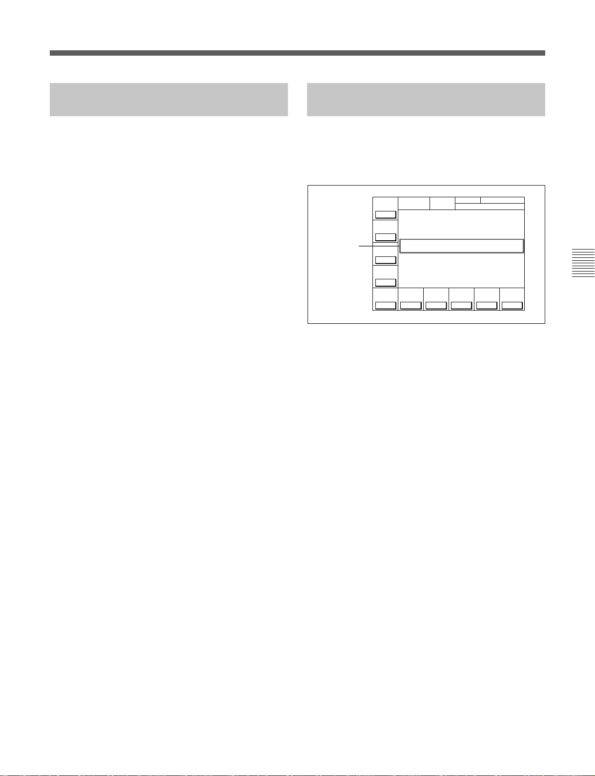
4-2-8 Selecting DMC Playback (DMC)
4-2-9 Recalling Edit Points (LAST EDIT)
In DMC (Dynamic Motion Control) playback mode,
the VTR plays back a tape segment at a specified
variable speed of –1 to +2 times normal playback
speed, memorizes the speed, then plays the segment
back at a later time at the memorized speed.
DMC playback is useful during on-the-spot telecasts of
sporting events for immediate playback and broadcast
of highlight scenes for which starting and ending
points have been set during recording.
For detail on the procedure for DMC playback, see Section
5-4-4, “DMC Playback” on page 5-13.
During tape editing using two HDW-F500 VTRs, you
can use DMC playback to control the playback speed
of the player VTR for editing at variable speeds (DMC
editing).
For detail on the procedure for DMC editing, see Section
6-2-1, “Performing DMC Editing” on page 6-15.
While editing, you can recall the last edit points by
pressing the ALT button, then the [F10] (LAST EDIT)
button.
The edit points appear in the display.
HOME
BÅSEBÅLL EDIT SET
INS
INS
INS
Å-CH4
off
CUE
off
off
Edit points
PB/EE
PLAY LOCK
PB
TCR 2FD F1
RECINH
off
ÅIN 00:01:10:00 ÅOUT 00:02:10:00
ÅSSEM-
IN 00:01:10:00 OUT 00:02:10:00
BLE
off
INS
TC
off
INS
VIDEO
off
CH.COND
GREEN
01Ó 04µ 58ß 00ƒ
INS
INS
Å-CH1
Å-CH2
off
Å-CH3
off
Recalling edit points (LAST EDIT)
Chapter 4 Menu Settings
Chapter 4 Menu Settings 4-19
Page 60

4-3 TC Menu
4-3 TC Menu
The TC menu allows you to set time code-related
items through a single menu. The HOME, TC, PF1
and PF2 menus show information that includes the
VTR operation mode, time code of the current
position, and the time code type, etc.
TCR: Time data type
(CTL/TCR/UBR/TCG/UBG/DUR)
VITC: Time code type (LTC/VITC)
Chapter 4 Menu Settings
For details on operation modes, refer to “4-2 HOME
Menu” on page 4-14.
Button
[F1]
[F2]
[F3]
[F4]
[F5]
[F6]
[F7]
[F8]
[F9]
[F10]
ALT/[F1]
ALT/[F2]
ALT/[F3] TC CONV Specifies whether or not to convert the 24F time
ALT/[F4] PDTC DISP Specifies whether or not to display pull down time
ALT/[F5] PD CHARA on, offSpecifies superimposition of character information
ALT/[F6] CHARA SUPER
ALT/[F7] CHARA H-POS Changes the superimposition position (horizontal). 0-15
ALT/[F8] CHARA V-POS Changes the superimposition position (vertical). 0-23
ALT/[F9]
ALT/[F10] VITC POS-2 12-20
To activate the TC menu
Press the TC button.
To change the TC menu page
Press the ALT button.
INTRP (interpolation): This appears when time
code cannot be read correctly and correction
has been performed.
Data entry window
F1: Field number (F1/F2)
DF: This appears when drop frame mode data is
being recorded or played (DF/NDF).
AIN: Time data for an AUDIO IN point
AOUT: Time data for an AUDIO OUT point
IN: Time data for an IN point
OUT: Time data for an OUT point
RUN
MODE
rec
TC Menu
TC
DF/NDFDFVITC
TCG
REMAIN-T
TIMER
L 113min
SEL
TC
PLAY LOCK
TCR VITC INTRP DF 2FD F1
TIMER
RESET
ÅIN 00:01:10:00 ÅOUT 00:02:10:00
TIMER
IN 00:01:10:00 OUT 00:02:10:00
SET
TIMER
HOLD
TC
SEL
SOURCE
VITC
int-L
CH.COND
GREEN
01Ó 04µ 58ß 00ƒ
TCG
TCG
MODE
prst
TC menu
Indication
TIMER SEL
TIMER RESET
TIMER SET
TIMER HOLD
TCR SEL
TCG SOURCE
TCG MODE
RUN MODE
DF/NDF
VITC
TAPE TIMER
PDPSET MENU
Function
Selects time data type.
Resets the time counter.
Sets the time data.
Holds the time counter.
Sets the time code reader.
Selects the internal/external time code generator.
Sets the time code generator.
Selects the running mode of the time code.
Selects drop frame mode.
Selects VITC input source
Selects the CTL display mode.
Activates the PDPSET menu.
code to the 25F time code when playing back the
cassette tape recorded in the 24F mode with the
25F mode.
code.
to the pull down output.
Specifies superimposition of character information
to the HD SDI output and HD-SD converter output.
VITC POS-1 Selects the VITC insertion line in the HD-SD
converter output.
Settings
CTL, TC, UBIT
VITC, auto, LTC
int-LTC, int-VITC
ext-LTC, ext-VITC
regene, prst, auto
free, rec
DF, NDF, auto
TCG, V IN
+/–12H, 24H
on, off
on, off
on, off
12-20
4-20 Chapter 4 Menu Settings
Page 61

4-3-1 Setting the Time Data (TIMER SEL/RESET/SET/HOLD)
The display shows the following types of time data:
Indication Time data type
TCR LTC
TCR VITC
TCG
CTL
UBR LTC The user bits
UBR VITC The user bits value read by the
UBG
DUR
Superimposed
display
TCR
TCR.
TCG
CTL
UBR
UBR.
UBG
DUR
The LTC1) value read by the
time code reader during
playback.
1)
The VITC
value read by the
time code reader during
playback.
The value generated by the
time code generator during
recording.
The number of CTL signals
2)
on the tape during recording/
playing.
3)
value read by
the time code reader (LTC)
during playback.
time code reader (VITC) during
playback.
The user bits value generated
by the time code generator
during recording.
Appears whenever a duration
between any two edit points
(IN, OUT, AUDIO IN or AUDIO
OUT points) is displayed.
RUN
MODE
rec
TC
Time data for
edit points
DF/NDFDFVITC
TCG
REMAIN-T
TIMER
L 113min
SEL
TC
PLAY LOCK
TCR VITC DF 2FD F1
TIMER
RESET
ÅIN 00:01:10:00 ÅOUT 00:02:10:00
TIMER
IN 00:01:10:00 OUT 00:02:10:00
SET
TIMER
HOLD
TC
SEL
SOURCE
VITC
CH.COND
GREEN
01Ó 04µ 58ß 00ƒ
TCG
TCG
MODE
int-L
prst
Selecting the time data display
Press the [F1] (TIMER SEL) button repeatedly to
select the desired time data display.
CTL: Counts the CTL signals on the playback tape
or the CTL signals being recorded on the tape, and
displays the tape running time in hours, minutes,
seconds, and frames.
TC: Displays the value read by the time code reader
or the value generated by the time code generator.
To switch between VITC and LTC, press the [F5]
(TCR SEL) button.
UBIT: Displays user bits data inserted in time code
being played back, or the user bits data inserted in
time code being recorded. To switch between
VITC and LTC, press the [F5] (TCR SEL) button.
Chapter 4 Menu Settings
Time data for IN, OUT, AUDIO IN and AUDIO OUT
points are also displayed.
..........................................................................................................................................................................................................
1) LTC and VITC
LTC cannot be read when the tape speed is very slow or
is changed suddenly. VITC, on the other hand, can be
read more accurately than LTC when the VTR is stopped
or the tape speed is very low. VITC, however, cannot be
read when the tape speed is very fast.
2) CTL signals
CTL (control) signals are pulse signals that are recorded
horizontally in each frame.
3) User bits
Comprising a part of the time code, user bits record
supplementary information and consist of an eight-digit
number or hexadecimal A to F.
Chapter 4 Menu Settings 4-21
Page 62

4-3 TC Menu
Selecting the time code and the user bits
to be recorded
Use the [F6] (TCG SOURCE), [F7] (TCG MODE),
[F9] (DF/NDF), and [F10] (VITC) buttons in the TC
menu to specify the time code and the user bits to be
recorded. The specifications for the various button
settings are shown in the following table.
[F10] (VITC) [F7] (TCG
V IN Records the time code and the user bits input from the HD SDI
Chapter 4 Menu Settings
TCG prst DF/NDF/
MODE)
3)
regene
auto “regene” is set in assemble or insert mode and “prst” is set in
[F6] (TCG
SOURCE)
int-LTC The time code value generated by the time code generator and
int-VITC The time code value generated by the time code generator and
ext-LTC The time code value generated by the time code generator and
ext-VITC The time code value generated by the time code generator and
[F9] (DF/NDF) Time code and user bits recorded
1)
connector to the video signal
auto
INPUT or SDTI (OPTION) IN
AUX data area. The time code value generated by the time
code generator specified by the [F6] and [F7] buttons and the
user bits value generated by the user bits generator are
recorded longitudinally on the tape.
2)
The time code value generated by the time code generator and
the user bits value generated by the user bits generator are
recorded. Any time code can be specified for the time code
generator and the user bits generator. The running mode for
the recorded time code data conforms to that specified by the
[F9] button.
the user bits value generated by the user bits generator are
recorded. The time code generator and the user bits generator
lock to the time data recorded longitudinally on the tape.
the user bits value generated by the user bits generator are
recorded. The time code generator and the user bits generator
lock to the time data recorded in the video signal AUX data
area on the tape.
the user bits value generated by the user bits generator are
recorded. The time code generator and the user bits generator
lock to the time data input from the TIME CODE IN connector.
the user bits value generated by the user bits generator are
recorded. The time code generator and the user bits generator
lock to the time data input from the HD SDI INPUT or SDTI
(OPTION) IN
other modes.
1)
connector.
..........................................................................................................................................................................................................
1) The SDTI (OPTION) IN connector is operative only
when the optional HKDV-506A SDTI Board is installed
and 701.VIDEO INPUT select in the VTR SETUP menu
is set to SDTI.
3) Specify the signal to be regenerated with 608.TCG/UBG
REGENE MODE in the VTR SETUP menu. Signals not
specified by this menu item are automatically set to
Preset mode, regardless of the [F7] button setting.
2) The DF/NDF setting on the [F9] button is applied to the
time code only when prst is specified by the [F7] button;
the DF/NDF setting is always applied for the CTL timer.
4-22 Chapter 4 Menu Settings
Page 63

Setting time codes
To cancel entered values
Press the CLR button.
To set time codes, select prst with the [F7] (TCG
MODE) button in the TC menu and then follow the
steps below.
Note
•Set the [F8] (RUN MODE) button to rec before
setting the time data for recording. When you select
rec, time data advances from a set value only during
recording. When you select free, time code advances
in real time after the initial value has been set.
•During recording, VITC is always written to the
AUX data area of the video signal.
1342
Setting time codes
1 Press the [F1] (TIMER SEL) button to select the
TC (time code) to be set.
2 Enter the new setting in the data entry window
with the numeric buttons.
For example, to enter 01H00M30S00F, press 1, 0,
0, 3, 0, 0, 0. (The leading 0 is not required. When
the entered value is less than eight digits, the
leading digit(s) is (are) set to 0 when you press the
SET button.)
3 Press the SET button to set the entered
value.
If you pressed the + or – button, then entered a
value, the result of calculation appears in the
display.
SET is displayed.
REMAIN-T
TIMER
L 113min
SEL
TC
PLAY LOCK
TCR VITC 2FD F1
TIMER
RESET
ÅIN 00:01:10:00 ÅOUT 00:02:10:00
TIMER
IN 00:01:10:00 OUT 00:02:10:00
SET
TIMER
HOLD
TC
SEL
SOURCE
VITC
CH.COND
GREEN
01Ó 04µ 58ß 00ƒ
TCG
TCG
MODE
int-L
prst
TC
SET 01 00 30 00
RUN
DF/NDFDFVITC
MODE
rec
TCG
4 Press the [F3] (TIMER SET) button.
The input value is set as the time code and appears
in the time data display section.
Notes
•Time codes from an external time code generator
cannot be set.
•Time codes cannot be set when the internal time code
generator is locked to external time codes or to time
codes read by the time code reader.
Chapter 4 Menu Settings
REMAIN-T
TIMER
L 113min
SEL
TC
PLAY LOCK
TCR VITC 2FD F1
TIMER
RESET
ÅIN 00:01:10:00 ÅOUT 00:02:10:00
TIMER
IN 00:01:10:00 OUT 00:02:10:00
SET
TIMER
HOLD
TC
SEL
SOURCE
VITC
CH.COND
GREEN
01 00 30 00
01Ó 04µ 58ß 00ƒ
TCG
TCG
RUN
MODE
prst
MODE
rec
int-L
TC
DF/NDFDFVITC
TCG
Data entry
window
Chapter 4 Menu Settings 4-23
Page 64

4-3 TC Menu
Setting the CTL timer
1 Select CTL using the [F1] (TIMER SEL) button.
2 Enter data in the data entry window using the
number buttons.
3 Press the SET button to set the data.
4 Press [F3] (TIMER SET).
Note
When ±12H is selected in the 604.TAPE TIMER
DISPLAY setting in the VTR SETUP menu and a
value of 10H or more is entered, the first digit will be
Chapter 4 Menu Settings
dropped.
Resetting time data
Press the [F2] (TIMER RESET) button.
The internal time code generator is reset according to
the setting of the [F1] (TIMER SEL) button.
Resetting TC or UBIT data
The internal time code generator is reset and the time
data display becomes 00H00M00S00F (TC) or 00 00
00 00 (UBIT). Edit points are not affected.
Notes
•Time data read by the time code reader cannot be
reset.
•Time data cannot be reset when the internal time code
generator is locked to external time codes or to time
codes read by the time code reader.
Recording the current time
1 Select DF by pressing the [F9] (DF/NDF) button.
2 Select free by pressing the [F8] (RUN MODE)
button.
3 Enter the target time with the numeric buttons
while verifying the data in the data entry window.
4 When the target time arrives, press the [F3]
(TIMER SET) button.
The time code generator starts operating from the
specified time.
To pause the current time
Press the [F4] (TIMER HOLD) button.
The time is paused only while the button is held down.
4-3-2 Setting the Time Code Reader (TCR SEL)
Press the [F5] (TCR SEL) button to select the time
code to be read by the time code reader during
playback.
VITC: Reads VITC.
auto: Reads VITC when the playback speed is +/–1/
2 times normal speed or less, and LTC when it is
greater than +/–
LTC: Reads LTC.
Depending on the time code recorded on a tape, VITC
or LTC appears on the display.
1
/2 times normal speed.
Setting the user bit value
1 Select UBIT by pressing the [F1] (TIMER SEL)
button.
2 Enter the desired user bit value in hexadecimal
notation using the numeric buttons.
(Press the 0 to 5 buttons while holding down the
SFT button to enter the letters A to F.)
3 Press the [F3] (TIMER SET) button.
4-24 Chapter 4 Menu Settings
Note
Time codes that are read by the time code reader or
played back are output from the TIME CODE OUT
connector.
Page 65

4-3-3 Setting the Time Code Generator (TCG SOURCE/MODE)
Regenerated signals are selected using the 608.TCG/
UBG REGENE MODE setting in the VTR SETUP
menu.
There are two ways to record time codes on the VTR.
One way is to record the output of the VTR’s internal
time code generator. The other is to directly record
time codes that are input from an external time code
generator.
The output from the internal time code generator can
either be set to a specified initial value, or
synchronized with an external time code generator.
The internal time code generator time code settings are
made with the [F6] (TCG SOURCE)/[F7] (TCG
MODE) buttons. Menu selections and settings are
shown below.
Menu [F6] (TCG
TCG
Internal
TCG
(Preset)
Internal
TCG
(Regenerate)
SOURCE)
int-LTC regene Lock to the time
int-VITC regene Lock to the time
ext-LTC regene Lock to the time
ext-VITC regene
[F7] (TCG
MODE)
prst Time codes can
auto “regene” is set in
Setting
be freely set
using the
internal time
code generator
data recorded
on the time code
tracks
data recorded
as video AUX
data on the tape
data on the
TIME CODE IN
connector
Lock to the time
data in the video
signal on the HD
SDI INPUT
connector
assemble or
insert mode and
“prst” is set in
other modes
To check the running of the internal time code
generator
Press the INPUT CHECK button.
4-3-4 Selecting the Time Code Running Mode (RUN MODE)
Press the [F8] (RUN MODE) button to select the time
code running mode.
free: The time code advances when the power is on
regardless of the VTR’s operation mode.
rec: The time code advances only during recording.
4-3-5 Selecting the Drop Frame Mode (DF/NDF)
Press the [F9] (DF/NDF) button to select the running
mode for the CTL counter and the time code generator.
DF: Drop frame mode
NDF: Non-drop frame mode
auto: The unit switches to drop frame mode when the
field frequency is 59.94 Hz, and switches to nondrop frame mode when the field frequency is
60 Hz.
Note
•This setting is only active when the frame frequency
of the unit is 29.97 Hz or 30 Hz.
•When the [F7] (TCG MODE) button is set to regene,
the drop frame mode is inoperative since the time
code generator is synchronized to the playback time
code.
1)
(DF is displayed.)
2)
(NDF is displayed.)
Chapter 4 Menu Settings
Note
..........................................................................................................................................................................................................
1) Drop frame mode
In order to compensate for differences between time
code values from the time code generator and the actual
time that occurs when the field frequency of this unit is
59.94 Hz, the drop frame mode causes the time code
generator to omit the first two frames (frame 00 and 01)
in each minute except the tenth.
2) Non-drop frame mode
In this mode, drop frame mode processing is not
performed. Since there is no frame cutting, a
discrepancy of about 86 seconds occurs each day (in the
case of a field frequency of 59.94 Hz).
Chapter 4 Menu Settings 4-25
Page 66

4-3 TC Menu
4-3-6 Inserting VITC input source (VITC)
Press the [F10] (VITC) button to select the VITC
source to be written in the video signal AUX data area.
TCG: Inserts values generated by the internal time
code generator into the VITC.
V IN: Inserts the VITC from the video input signal
directly.
4-3-7 Selecting CTL Display Mode (TAPE TIMER)
Chapter 4 Menu Settings
Press the ALT button, then the [F1] (TAPE TIMER)
button to select a 12-hour or 24-hour clock for the
CTL display.
+/–12H: 12-hour clock
24H: 24-hour clock
2 Press the [F2] (PDPSET MENU) key.
The PDPSET menu appears.
PRESET
MODE
24F
PDTIME
SET
REMAIN-T
L 113min
24F TC
CH.COND
GREEN
00Ó 00µ 00ß 00ƒ
30F TC
00Ó 00µ 00ß 00ƒ
PDTC
DF/NDF
NDF
PDPSET
TCR 00:00:00:00
EXIT
3 Press the [F1] (PRESET MODE) key to select 24F
or 30F time code to be preset. The selected time
code is framed with the thick line.
24F: Presets the 24 frames time code. The A
frame of the pull down sequence is preset.
30F: Presets the 30 frames time code. The A
frame of the pull down sequence is preset.
4-3-8 Presetting Pull Down Time Code (PDPSET MENU) (when HKDV-507 is installed)
To preset the pull down time code, follow the steps
below.
4
2,7
3
65
1
1 Press the TC button, then press the ALT button.
The ALT+TC menu appears.
4 •When 30F is selected in the step 3,
Press the [F6] (PDTC DF/NDF) key to select DF
or NDF.
This selection is effective only for 30F time code.
DF: Drop frame mode
NDF: Non-drop frame mode
auto: The unit switches the running mode (DF/
NDF) automatically according to the frame
frequency of the unit. When the frame
frequency is 23.976 Hz, the unit switches to the
drop frame mode and switches to the non-drop
frame mode when it is 24 Hz.
•When 24F is selected in the step 3,
Skip this step.
5 Enter the time code data in the data entry window
with numeric keys.
PRESET
MODE
24F
PDTIME
SET
REMAIN-T
L 113min
24F TC
CH.COND
GREEN
00Ó 00µ 00ß 00ƒ
PDPSET
01 00 30 00
TCR 00:00:00:00
Data entry
window
4-26 Chapter 4 Menu Settings
30F TC
00Ó 00µ 00ß 00ƒ
PDTC
DF/NDF
DF
EXIT
Page 67

6 Press the SET button to set the input data.
SET is
PRESET
MODE
24F
PDTIME
SET
REMAIN-T
L 113min
24F TC
CH.COND
GREEN
PDPSET
SET 01 00 30 00
TCR 00:00:00:00
00Ó 00µ 00ß 00ƒ
30F TC
00Ó 00µ 00ß 00ƒ
PDTC
DF/NDF
DF
EXIT
displayed.
7 Press the [F2] (PDTIME SET) key.
4-3-9 Conversion of Time Code When Playing Back in the 25F Mode (TC CONV)
When the cassette tape recorded in the 24F mode is
played back in the 25F mode (off-speed playback), it is
possible to convert the 24 frames time code to the 25
frames time code. To set the conversion, press the
ALT/[F3] (TC CONV) key.
off: Does not convert the 24 frames time code to the
25 frames time code.
on: Converts the 24 frames time code to the 25
frames time code.
PRESET
MODE
24F
PDTIME
SET
CH.COND
REMAIN-T
L 113min
24F TC
GREEN
01Ó 00µ 30ß 00ƒ
30F TC
00Ó 00µ 00ß 00ƒ
PDTC
DF/NDF
DF
PDPSET
TCR 00:00:00:00
EXIT
Notes
• Once the time code is preset, it cannot be reverted.
• Operation information display cannot be displayed
while the pull down time code appears.
• The pull down time code cannot be displayed while
the machine-to-machine editing display appears.
The total amount of frames of the current time code is
calculated using 00H00M00S00F of the 24 frames
time code as a reference, and then it is converted to the
25 frames. For example, 00:00:10:20 of the 24 frames
time code is converted to 00:00:10:10 of the 25 frames
time code, and 23:59:50:00 to 23:59:50:10.
Note
•This setting is only active when the frame frequency
of the unit is 25 Hz.
•This setting is effective only for the VITC and time
code of SONY 9PIN protocol. From the TIME
CODE OUT connector, 24 frames time code is
output.
Chapter 4 Menu Settings
Chapter 4 Menu Settings 4-27
Page 68

4-3 TC Menu
4-3-10 Displaying the Pull Down Time Code (when HKDV-507 is installed)
To display the pull down time code, follow the steps
below.
Chapter 4 Menu Settings
1 Press the TC button, then press the ALT button.
TAPE
TIMER
12H
PDPSET
MENU
CONV
off
PDTC
DISP
off
CHARA
off
2
CH.COND
PLAY LOCK
TCR 2FD F1
GREEN
00Ó 00µ 00ß 00ƒ
ÅIN 00:01:10:00 ÅOUT 00:02:10:00
TC
IN 00:01:20:00 OUT 00:02:20:00
PD
00Ó 00µ 00ß 00ƒ
PD
CHARA
CHARA
H-POS
10
CHARA
V-POS
10
SUPER
off
ALT+TC
VITC
POS-1
16
VITC
POS-2
16
4-3-11 Superimposition of Character Information (PD CHARA/CHARA SUPER/H-POS/ V-POS)
To superimpose the characters representing time code
data and operation mode information on the output
signals, use the [F4] (PD CHARA) and [F6] (CHARA
SUPER) buttons.
Button Setting Connector to which the
characters are superimposed
ALT/[F4] on PULL DOWN OUT connector (on two
connectors)
ALT/[F6] on • HD SDI MONITOR connector
•COMPOSITE (SUPER) connector
of D CONV. OUT(OPTION)
•3(SUPER) of connector D CONV. SDI
OUT(OPTION)
Contents of superimposed data
1
2 Press the [F5] (PDTC DISP) key to select “on”.
on: Displays the pull down time code.
off: Does not display the pull down time code.
TAPE
TIMER
12H
PDPSET
MENU
TC
CONV
off
PDTC
DISP
off
PD
CHARA
off
CH.COND
PLAY LOCK
TCR 2FD F1
GREEN
01Ó 04µ 58ß 00ƒ
ÅIN 00:01:10:00 ÅOUT 00:02:10:00
IN 00:01:20:00 OUT 00:02:20:00
PLÅYER
01Ó 04µ 58ß 00ƒ
ÅIN 00:01:10:00 ÅOUT 00:02:10:00
IN 00:01:20:00 OUT 00:02:20:00
CHARA
CHARA
H-POS
10
CHARA
V-POS
SUPER
off
ALT+TC
VITC
VITC
POS-1
10
POS-2
16
16
1 Types of time data
Time data
2 Drop frame mark of the time
code reader
3 Drop frame mark of the time
code generator
4 Field mark of the
VITC data
T CR.23:59.40.18
SHUTTLESTI LL
*
5 Control VTR indication
Contents of superimposed data
Note
The example above shows the factory-set contents of
data.
By changing the 626.DISPLAY INFORMATION
select setting in the VTR SETUP menu, different types
of information can also be displayed on the second
line.
4-28 Chapter 4 Menu Settings
Page 69

1 Types of time data
Symbol Meaning
CTL CTL counter data
TCR LTC reader time code data
UBR LTC reader user bit data
TCR. VITC reader time code data
UBR. VITC reader user bit data
TCG Time code data from the time code generator
UBG User bit data from the time code generator
Note
When time data or user bits are not read correctly, a
“*” will be displayed in this block so that the symbols
become “T*R”, “U*R”, etc.
2 Time code reader drop frame marks
“ • ”: drop frame mode
“ : ”: non-drop frame mode
3 Time code generator drop frame marks
“ • ”: drop frame mode
“ : ”: non-drop frame mode
Chapter 4 Menu Settings
4 VITC data field marks
“ ”: (blank space) fields 1 and 3
“ * ”: fields 2 and 4
5 Operation mode
The contents are divided into blocks A and B as shown
below.
A block indicates the operation mode.
B block indicates the tape speed or servo lock status.
AB
Chapter 4 Menu Settings 4-29
Page 70

4-3 TC Menu
A block B block
TAPE UNTHREAD Cassette not inserted
STANDBY OFF Standby off mode
T.RELEASE Tension release mode
STOP Stop mode
PREROLL Preroll mode
PLAY Playback mode (servo unlocked)
PLAY LOCK Playback mode (servo locked)
PLY-SPD Speed shift from
REC Record mode (servo unlocked)
REC LOCK Record mode (servo locked)
Chapter 4 Menu Settings
EDIT Edit mode (servo unlocked)
EDIT LOCK Edit mode (servo locked)
JOG STILL Still-picture jog mode
JOG FWD Forward jog (” is lit)
JOG REV Reverse jog (“ is lit)
SHUTTLE (speed) Shuttle mode
VAR (speed) Variable mode
DMC (speeda)) DMC memorize mode
D-PREV (speeda)) DMC edit preview mode
DMC EDIT DMC edit mode
DMC-SPD (speed) DMC initial speed setting
PREVIEW Preview mode
AUTO EDIT Auto edit mode
REVIEW Review mode
a) Initial speed or memorized speed
Display
normal speed (%)
Operation modes
Operation mode
Capstan override mode
To display a warning message
TCR 23 59 4 0 1 8.:::
OXTRNLEFEEAR
N
The first 16 characters of the
warning message
*
E
Set 626. DISPLAY INFORMATION select in the
VTR SETUP menu to any setting other than time data
only and set 627. CHAR WARNING DISPLAY at
dual line mode in the VTR SETUP menu to on. The
first 16 characters of the warning message flashes on
the second line.
4-30 Chapter 4 Menu Settings
For details about the warning messages, see “Warning
Messages” on page A-10.
When there are multiple warning messages, each
message flashes twice before it is replaced by the next
message. When there is no warning message, the
items set in 626. DISPLAY INFORMATION select in
the VTR SETUP menu flashes on the second line
instead.
Page 71

To display remaining time on the tape
Use the 628.REMAIN TIME DISPLAY to display
remaining time on the tape.
off: Do not display remaining time.
10min: Display remaining time when it is 10
minutes or less.
on: Always display remaining time.
When remaining time is 23 minutes.
TCR23594018.:::
When remaining time is five minutes.
*
R2
4-3-12 Setting the VITC Insertion Line (VITC POS-1/POS-2)
VITC signals can be inserted at two positions between
lines 12 and 20 in the output signal from the HD-SD
converter.
3
TCR23594018.:::
When remaining time is 100 minutes or over.
TCR23594018.:::
Examples of remaining time display
R
R -
5
-
*
*
Changing the superimpose position
The superimpose position can be set to 16 different
positions in the horizontal directions (0-15) and 24
different positions in the vertical directions (0-23).
1,3
2
1,3
Setting the VITC insertion line (VITC POS-1/POS-2)
2
1 Press the ALT button, then the [F9] (VITC POS-1)
button.
The setting display part is lit.
2 Press the G or g button to change the value.
You can also use the + or – button.
3 Press the [F9] (VITC POS-1) button.
The data setting is completed and the setting
display disappears. Switching to another menu also
completes the setting display disappears.
Following the same steps but using the [F10] (VITC
POS-2) button, VITC can be inserted on another line.
Chapter 4 Menu Settings
1 Press the ALT/[F7] (CHARA H-POS) button to
change the horizontal position and the [F8]
(CHARA V-POS) to change the vertical position.
The setting display part is lit.
2 Use the [<] and [>] buttons to change the value.
The + and – buttons can also be used.
3 Press the ALT/[F7] (CHARA H-POS) button or the
[F8] (CHARA V-POS) button. The positions are
set and the setting display disappears.
The positions are also set if another menu is
selected.
Chapter 4 Menu Settings 4-31
Page 72

4-4 CUE Menu
4-4 CUE Menu
The HDW-F500 allows you to register up to 100 cue
points (0 to 99), and to manage cue points in groups of
10 (per page).
Cue point settings, deletions, and page settings are
done through the CUE menu.
For details on storing cue point data, refer to “4-1-5
Memory Card Function” on page 4-6.
To activate the CUE menu
Press the CUE button.
Chapter 4 Menu Settings
Page number indication
REMAIN-T
PREV
L 113min
PÅGE
[I ÅM CUE TITLE ]
NEXT
PÅGE: 0
PÅGE
1
2
3
4
5
6
7
8
9
CUE
P-ROLL
CH.COND
10 00:01:10:00
11 00:02:10:00
12 00:03:10:00
13 00:04:10:00
14 00:05:10:00
15 00:06:10:00
16 00:07:10:00
17 00:08:10:00
18 00:09:10:00
19 00:10:10:00
PÅGE
Note
Cue point data is factory set to be erased when a
cassette is inserted.
To select whether to erase cue point data
when a cassette is inserted.
Press the [F10] (M-CUE CLEAR) button to select
whether to erase cue point data when a cassette is
inserted.
on: Erase cue point data.
off: Do not erase cue point data.
Data entry window
CUE
SET
TCR 00:00:00:00EOS 00:00:00:00
CUENUM
SET
M-CUE
CLEAR
Title
Cue point indication
Button Indication Function
[F1]
[F2]
[F5]
[F8]
[F9]
[F10]
ALT/[F8]
ALT/[F9]
PREV PAGE Shows the previous page.
NEXT PAGE Shows the next page.
CUE P-ROLL Specifies the preroll time to a cue point.
PAGE SET Specifies the page number.
CUENUM SET Specifies the cue number.
M-CUE CLEAR Erases cue point data when a cassette is inserted.
PAGE MODE Selects PAGE mode.
EXTEND MODE Selects EXTEND mode.
CUE menu display
CUE menu
Settings
0 to 30 s
on, off
4-32 Chapter 4 Menu Settings
Page 73

4-4-1 Selecting a Multi-Cue Mode
4-4-2 Registering Cue Points
The HDW-F500 has the following two multi-cue
modes.
PAGE mode
Press the ALT button, then the [F8] (PAGE MODE)
button.
In PAGE mode, cue point data can be accessed by
page number, thus speeding up cue point registration
and cuing operations.
Display
Cue points are displayed in groups of 10, number 0 to
9, 10 to 19, etc. Each display is a page.
Selecting a page
There are the three following ways to select a page:
• Press the [F1] (PREV PAGE) button.
The previous page is shown.
• Press the [F2] (NEXT PAGE) button.
The next page is shown.
• Enter the desired page number with the numeric
button, then press the [F8] (PAGE SET) button.
If you enter 1, for example, page one appears,
containing cue point numbers 10 to 19.
There are two ways to register cue points: (1) by direct
registration of the tape address when the ENTRY
button is pressed, and (2) by the entry of cue point data
with the numeric buttons.
Registering cue points by pressing the
ENTRY button
2
1
Registering cue points by pressing the ENTRY button
5
3
4
1 Press the ALT button, then the [F8] (PAGE
MODE) button or the [F9] (EXTEND MODE)
button.
Chapter 4 Menu Settings
EXTEND mode
Press the ALT button, then the [F9] (EXTEND
MODE) button.
In EXTEND mode, you can do operations that cannot
be done in page units, such as the consecutive
registration of more than 10 cue points.
Display
The screen displays a list of 100 consecutive cue
points which can be scrolled. Press the G or g button
to scroll the list. Page columns are not displayed.
To quickly scroll through a list
Press the G or g button while holding down the SFT
button.
2 If you selected PAGE mode, press the [F1] (PREV
PAGE) button or [F2] (NEXT PAGE) button (or
use the numeric buttons to enter the page number
in the data entry window, then press the [F8]
(PAGE SET) button).
3 Press the G or g button to move the cursor (z ) to
the cue number to be registered.
REMAIN-T
PREV
L 113min
PÅGE
[I ÅM CUE TITLE ]
NEXT
PÅGE: 0
PÅGE
1
2
3
4
5
6
7
8
9
CUE
P-ROLL
CH.COND
10 00:01:10:00
11 00:02:10:00
12 00:03:10:00
13 00:04:10:00
14 00:05:10:00
15 00:06:10:00
16 00:07:10:00
17 00:08:10:00
18 00:09:10:00
19 00:10:10:00
PÅGE
SET
TCR 00:00:00:00EOS 00:00:00:00
CUE
CUENUM
SET
M-CUE
CLEAR
Chapter 4 Menu Settings 4-33
Page 74

4-4 CUE Menu
To select the cue number directly by
numeric buttons
Enter the cue number in the data entry window
with the numeric buttons, then press the [F9]
(CUENUM SET) button.
4 Press the JOG or VAR button, then rotate the
search dial to find the position where you want to
register the cue point.
5 Press the ENTRY button at the selected position.
The current tape address of the position where the
button is pressed is registered as a cue point.
Press the ENTRY button repeatedly to register the
cue point repeatedly. The cue number will
Chapter 4 Menu Settings
automatically increment by one each time.
REMAIN-T
PREV
L 113min
PÅGE
[I ÅM CUE TITLE ]
NEXT
PÅGE: 0
PÅGE
1
2
3
4
5
6
7
8
9
CUE
P-ROLL
CH.COND
10 00:01:10:00
11 00:02:10:00
12 00:03:10:00
13 00:04:10:00
14 00:05:10:00
15 00:06:10:00
16 00:07:10:00
17 00:08:10:00
18 00:09:10:00
19 00:10:10:00
PÅGE
SET
TCR 00:00:00:00EOS 00:00:00:00
CUE
CUENUM
SET
M-CUE
CLEAR
Registering cue points by the numeric
buttons
24
1
Registering cue points by the numeric buttons
5
3
1 Press the ALT button, then the [F8] (PAGE
MODE) button or the [F9] (EXTEND MODE)
button.
2 If you selected PAGE mode, press the [F1] (PREV
PAGE) button or [F2] (NEXT PAGE) button (or
use the numeric buttons to enter the page number
in the data entry window, then press the [F8]
(PAGE SET) button).
Note
In PAGE mode, the cue number advances only within
the current page when the ENTRY button is pressed
repeatedly. For example, after cue number 19 is
registered and the ENTRY button is pressed, the cue
point 10 comes up as the next cue point. In EXTEND
mode, if you press the ENTRY button after registering,
for example, cue point No.99, the next cue point is
registered to cue point No.99 again.
3 Press the G or g button to move the cursor (z ) to
the cue number to be registered.
REMAIN-T
PREV
L 113min
PÅGE
[I ÅM CUE TITLE ]
NEXT
PÅGE: 0
PÅGE
1
2
3
4
5
6
7
8
9
CUE
P-ROLL
CH.COND
10 00:01:10:00
11 00:02:10:00
12 00:03:10:00
13 00:04:10:00
14 00:05:10:00
15 00:06:10:00
16 00:07:10:00
17 00:08:10:00
18 00:09:10:00
19 00:10:10:00
PÅGE
To select the cue number directly by the
numeric buttons
Enter the cue number in the data entry window
with the numeric buttons, then press the [F9]
(CUENUM SET) button.
SET
TCR 00:00:00:00EOS 00:00:00:00
CUE
CUENUM
SET
M-CUE
CLEAR
4-34 Chapter 4 Menu Settings
Page 75

4 Enter the cue point data in the data entry window
with the numeric buttons, then press the SET
button.
For example, to enter 00:01:30:00, press 0, 0, 1, 3,
0, 0, 0. (The leading 0 is not required. When the
entered value is less than eight digits, the leading
digit(s) is (are) set to 0 when you press the SET
button.)
4-4-3 Erasing Cue Point Data
To erase any cue point data, blank out the data entry
window, then do the cue point registration procedure.
2
4
REMAIN-T
PREV
L 113min
PÅGE
[I ÅM CUE TITLE ]
NEXT
PÅGE: 0
PÅGE
1
2
3
4
5
6
7
8
9
CUE
P-ROLL
CH.COND
10 00:01:10:00
11 00:02:10:00
12 00:03:10:00
13 00:04:10:00
14 00:05:10:00
15 00:06:10:00
16 00:07:10:00
17 00:08:10:00
18 00:09:10:00
19 00:10:10:00
PÅGE
CUE
SET 00 01 30 00
TCR 00:00:00:00
CUENUM
SET
M-CUE
CLEAR
SET
Entered data
To modify current cue point data
Press the + or – button, enter the value to be added
or subtracted, then press the SET button.
The computation is performed and the results
appear in the data entry window.
5 Press the ENTRY button to set the entered data.
The data are registered in the cue point data
indication.
REMAIN-T
PREV
L 113min
PÅGE
[I ÅM CUE TITLE ]
NEXT
PÅGE: 0
PÅGE
1
2
3
4
5
6
7
8
9
CUE
P-ROLL
CH.COND
10 00:01:10:00
11 00:01:30:00
12 00:03:10:00
13 00:04:10:00
14 00:05:10:00
15 00:06:10:00
16 00:07:10:00
17 00:08:10:00
18 00:09:10:00
19 00:10:10:00
PÅGE
CUE
TCR 00:00:00:00
CUENUM
SET
SET
M-CUE
CLEAR
1
5
3
Erasing cue point data
1 Press the ALT button, then the [F8] (PAGE
MODE) button or the [F9] (EXTEND MODE)
button.
2 If you selected PAGE mode, press the [F1] (PREV
PAGE) button or [F2] (NEXT PAGE) button (or
use the numeric buttons to enter the page number
in the data entry window, then press the [F8]
(PAGE SET) button).
3 Press the G or g button to move the cursor (z ) to
the cue number to be erased.
REMAIN-T
PREV
L 113min
PÅGE
[I ÅM CUE TITLE ]
NEXT
PÅGE: 0
PÅGE
1
2
3
4
5
6
7
8
9
CUE
P-ROLL
CH.COND
10 00:01:10:00
11 00:02:10:00
12 00:03:10:00
13 00:04:10:00
14 00:05:10:00
15 00:06:10:00
16 00:07:10:00
17 00:08:10:00
18 00:09:10:00
19 00:10:10:00
PÅGE
SET
CUE
TCR 00:00:00:00EOS 00:00:00:00
CUENUM
M-CUE
SET
CLEAR
Chapter 4 Menu Settings
To select the cue number directly by
the numeric buttons
Enter the cue number in the data entry window
with the numeric buttons, then press the [F9]
(CUENUM SET) button.
(Continued)
Chapter 4 Menu Settings 4-35
Page 76

4-4 CUE Menu
4 Press the CLR button then the SET button.
“SET” appears in the data entry window.
REMAIN-T
PREV
L 113min
PÅGE
[I ÅM CUE TITLE ]
NEXT
PÅGE: 0
PÅGE
1
2
3
4
5
6
7
8
9
CUE
P-ROLL
5 Press the ENTRY button.
Chapter 4 Menu Settings
Data for the specified cue number are erased and
the data column becomes blank.
REMAIN-T
PREV
L 113min
PÅGE
[I ÅM CUE TITLE ]
NEXT
PÅGE: 0
PÅGE
1
2
3
4
5
6
7
8
9
CUE
P-ROLL
To erase all cue point data
Press the CLR button while holding down the SFT
button. A message asking you to confirm the
operation appears in the display.
In EXTEND mode, press the CLR button while
holding down the SFT button again to erase all
data for cue points No. 0 to No. 99.
In PAGE mode, press the CLR button while
holding down the SFT button again to erase data
for the cue points on the current page.
CH.COND
SET
TCR 00:00:00:00EOS 00:00:00:00
10 00:01:10:00
11 00:02:10:00
12 00:03:10:00
13 00:04:10:00
14 00:05:10:00
15 00:06:10:00
16 00:07:10:00
17 00:08:10:00
18 00:09:10:00
19 00:10:10:00
PÅGE
CH.COND
PÅGE
CUENUM
SET
TCR 00:00:00:00EOS 00:00:00:00
10 00:01:10:00
11
12 00:03:10:00
13 00:04:10:00
14 00:05:10:00
15 00:06:10:00
16 00:07:10:00
17 00:08:10:00
18 00:09:10:00
19 00:10:10:00
CUENUM
SET
CUE
SET
CUE
SET
M-CUE
CLEAR
M-CUE
CLEAR
Data entry
window
Erased cue point
4-4-4 Prerolling to a Cue Point
Select the preroll time to a cue point with pressing the
[F5] button.
You can set a preroll time of 0 to 30 seconds in 1second units.
Prerolling to a cue point
2
1
Prerolling to a cue point
34
1 Press the ALT button, then the [F8] (PAGE
MODE) button or the [F9] (EXTEND MODE)
button.
2 If you selected PAGE mode, press the [F1] (PREV
PAGE) button or [F2] (NEXT PAGE) button (or
use the numeric buttons to enter the page number
in the data entry window, then press the [F8]
(PAGE SET) button).
3 Press the G or g button to move the cursor (z ) to
the cue number.
To select the cue number directly by the
numeric buttons
Enter the cue number in the data entry window
with the numeric buttons, then press the [F9]
(CUENUM SET) button.
4-36 Chapter 4 Menu Settings
4 Press the PREROLL button.
Page 77

4-4-5 Changing a Cue Point Into an Edit Point
Follow the procedures below to change a selected cue
point into an edit point.
To change an edit point into an IN point
Press the SET button while hoding down the IN
button.
To change an edit point into an OUT point
Press the SET button while holding down the OUT
button.
To change an edit point into an AUDIO IN
point
Press the SET button while holding down the AUDIO
IN button.
To change an edit point into an AUDIO OUT
point
Press the SET button while holding down the AUDIO
OUT button.
4-4-6 Backspace Editing
You can perform backspace editing with the CUE
menu. In backspace editing, assemble editing is
performed from the recording end point. Since the
data specifying recording end point are cleared when
you eject the tape, after inserting a tape, you must
record for at least one minute or so on the tape before
you can do backspace editing. After recording, the
present end of the recorded position becomes the
recording end point. When you press the REC/EDIT
button afterwards, the VTR automatically prerolls a
few seconds before the recording end point and starts
assemble editing. If no data for the recording end
point exist, backspace editing is not performed.
Chapter 4 Menu Settings
Note
Cue point data is cleared when a cassette is inserted.
However, cue point data recalled from a memory card
before a cassette is inserted is not cleared when a
cassette is inserted.
AUDIO IN button
IN button
OUT button
AUDIO OUT button
SET button
Chapter 4 Menu Settings 4-37
Page 78

4-5 PF1 Menu (Factory Settings)
4-5 PF1 Menu (Factory Settings)
The PF (Personal Function) 1 menu is used to register
frequently used menu items.
When shipped from the factory, the PF1 menu contains
the adjustment menu for video signals. If you later use
the PF1 menu to register items from other menus, you
can restore the PF1 menu to its original factory settings
by recalling SETUP BANK F from the VTR memory
banks.
Chapter 4 Menu Settings
Button
[F1] Selects the input video signal.
For details on registration methods, see Section 4-1-3,
“Registering Items to the PF1/2 Menus” on page 4-3, and
on restoring factory-set menu items, see Section 4-1-4,
“VTR Memory Bank Function” on page 4-4.
To activate the PF1 menu screen
Press the PF1 button.
REMAIN-T
VIDEO
L 113min
IN
SDI
PLAY LOCK
TCR 2FD F1
SERVO
REF
input
ÅIN --:--:--:-- ÅOUT --:--:--:- IN --:--:--:-- OUT --:--:--:--
MASTER
(HD)
prst
Y
(HD)
prst
PF1 menu (factory settings)
Indication Settings
Function
VIDEO IN
CH.COND PF1
00Ó 00µ 00ß 00ƒ
PB
PR
SETUP
H PHAS
(HD)
(HD)
prst
prst
PF1 menu display
(HD)
prst
(HD)
prst
FINE
(HD)
prst
SDI, SDTI
Note
The SDTI selection is operative only when the
optional HKDV-506A SDTI Board is installed.
[F2]
SERVO REF
Selects the reference signal for
ext, input, auto
output.
[F4]
MASTER LEVEL (HD)
Adjusts the Y, P
B, and PR output levels
prst, 0.0 to 141.3%
simultaneously.
[F5] Adjusts the Y output level. prst, 0.0 to 141.3%
[F6] Adjusts the P
[F7]
[F8]
[F9] Adjusts the sync phase.
[F10] FINE (HD) Fine adjustment of the sync phase
ALT/[F1] Adjusts the Y, B-Y, and R-Y output
Y LEVEL (HD)
P
B LEVEL (HD)
P
R LEVEL (HD)
SETUP LEVEL (HD)
SYNC PHASE (HD)
MASTER LEVEL (D1)
B output level.
Adjusts the PR output level.
Adjusts the setup level.
prst, 0.0 to 141.3%
prst, 0.0 to 141.3%
prst, –10.0 to +10.0
prst, –128 to +127
prst, 0 to 1024
prst, 0.0 to 141.3%
levels simultaneously.
ALT/[F2] Y LEVEL (D1) Adjusts the Y output level.
ALT/[F3]
B-Y LEVEL (D1)
Adjusts the B-Y output level.
ALT/[F4] R-Y LEVEL (D1) Adjusts the R-Y output level.
ALT/[F5] VIDEO LEVEL (D2) Adjusts the video level.
ALT/[F6] CHROMA LEVEL (D2) Adjusts the chroma level.
ALT/[F7] HUE (D2) Adjusts the hue.
ALT/[F8] SETUP LEVEL (D1/D2) Adjusts the setup level.
ALT/[F9] SYNC PHASE (SD) Adjusts the sync phase.
ALT/[F10] FINE (SD) Fine adjustment of the sync phase
prst, 0.0 to 141.3%
prst, 0.0 to 141.3%
prst, 0.0 to 141.3%
prst, 0.0 to 141.3%
prst, 0.0 to 141.3%
prst, –30 to +30
prst, 0 to +10.0
prst, –128 to +127
prst, 0 to 1024
4-38 Chapter 4 Menu Settings
Page 79

4-5-1 Selecting the Input Video Signal (VIDEO IN)
Press the [F1] (VIDEO IN) button repeatedly to select
the video signal to input.
SDI: SDI video signal input to the HD SDI INPUT
connector
SDTI (Only if the optional HKDV-506A SDTI Board
is installed.): Dubbing signal (270 Mbps) input to
the SDTI (OPTION) IN connector.
Notes
The time codes to be recorded depend on the settings
of the TC menu.
4-5-3 Adjusting the Output Video Signal (MASTER LEVEL to FINE)
Adjusting the output video signal
Follow the procedure below to adjust the output video
signal.
Chapter 4 Menu Settings
4-5-2 Selecting the Reference Signal (SERVO REF)
Press the [F2] (SERVO REF) button to select the
signal to be used as the reference signal for VTR
operations.
ext: The servo reference signal is forced to be EXT.
input: The signal from the HD SDI INPUT or SDTI
(OPTION) IN is used as the reference signal for
VTR operations. The [F1] (VIDEO IN) button
switches the video input signal.
auto: During recording or edit preset, the signal from
the HD SDI INPUT or SDTI (OPTION) IN is
used as a reference signal. In all other cases, the
servo operates using the signal setting of item
006.EXTERNAL REFERENCE select in the VTR
SETUP menu. If the signal selected in
006.EXTERNAL REFERENCE select is not
present, the servo operates using an internal
reference.
1,3
1,3
Adjusting the output video signal
2
1 Press the function button ([F4] to [F10]) whose
setting you wish to set.
The setting display section lights up.
2 Change the numerical value by pressing the G or
g button (or + or – button).
To change the value quickly, press the buttons
while holding down the SFT button.
To set the preset value
Press the center cursor button.
prst appears over the respective function button.
3 Press the function button ([F4] to [F10]) after
adjusting the numerical value.
Chapter 4 Menu Settings 4-39
Page 80

4-5 PF1 Menu (Factory Settings)
Adjusting the master output level (HD)
Make this adjustment with the [F4] (MASTER
LEVEL) button.
Adjusting the Y output level (HD)
Make this adjustment with the [F5] (Y LEVEL) button.
Chapter 4 Menu Settings
Adjusting the PB output level (HD)
Make this adjustment with the [F6] (PB LEVEL)
button.
prst: 100% (4000H)
Numerical value: 0.0 to 141.3%
Adjustable range: –∞ to +3 dB
prst:
Numerical value: 0.0 to 141.3%
Adjustable range: –∞ to +3 dB
prst: 100% (4000H)
Numerical value: 0.0 to 141.3%
Adjustable range: –∞ to +3 dB
Adjusting the sync phase (HD)
Use this setting to precisely match the output phase of
the VTR to the reference signal or when using a
switcher or other device connected to another VTR to
create special effects such as fading, wrapping, and
dissolving.
To adjust the output signal sync phase with respect to
the reference input, make this adjustment with the [F9]
(SYNC PHASE) button.
prst: 0 (0)
Numerical value: –128 to +127
Adjustable range: –1.4 to +1.4H
Fine adjustment of the sync phase (HD)
Make this adjustment with the [F10] (FINE) button.
prst: 0 (0)
Numerical value: 0 to 1024
Adjustable range: 0 to 323 nsec
Adjusting the master output level (D1)
Adjusting the PR output level (HD)
Make this adjustment with the [F7] (PR LEVEL)
button.
prst: 100% (4000H)
Numerical value: 0.0 to 141.3%
Adjustable range: –∞ to +3 dB
Adjusting the setup level (HD)
Make this adjustment with the [F8] (SETUP LEVEL)
button.
prst: 0% (0)
Numerical value: –10.0 to +10.0
Adjustable range: –10 to +10%
Make this adjustment with the ALT/[F1] (MASTER
LEVEL) buttons.
prst: 100% (4000H)
Numerical value: 0.0 to 141.3%
Adjustable range: –∞ to +3 dB
Adjusting the Y output level (D1)
Make this adjustment with the ALT/[F2] (Y LEVEL)
buttons.
prst: 100% (4000H)
Numerical value: 0.0 to 141.3%
Adjustable range: –∞ to +3 dB
Adjusting the B–Y output level (D1)
Make this adjustment with the ALT/[F3] (B–Y
LEVEL) buttons.
prst: 100% (4000H)
Numerical value: 0.0 to 141.3%
Adjustable range: –∞ to +3 dB
4-40 Chapter 4 Menu Settings
Page 81

Adjusting the R–Y output level (D1)
Adjusting the sync phase (D1/D2)
Make this adjustment with the ALT/[F4] (R–Y
LEVEL) buttons.
prst: 100% (4000H)
Numerical value: 0.0 to 141.3%
Adjustable range: –∞ to +3 dB
Adjusting the video output level (D2)
Make this adjustment with the ALT/[F5] (VIDEO
LEVEL) buttons.
prst: 100% (4000H)
Numerical value: 0.0 to 141.3%
Adjustable range: –∞ to +3 dB
Adjusting the chroma output level (D2)
Make this adjustment with the ALT/[F6] (CHROMA
GAIN) buttons.
prst: 100% (4000H)
Numerical value: 0.0 to 141.3%
Adjustable range: –∞ to +3 dB
Use this setting to precisely match the output phase of
the VTR to the reference signal or when using a
switcher or other device connected to another VTR to
create special effects such as fading, wrapping, and
dissolving.
To adjust the output signal sync phase with respect to
the reference input, make this adjustment with the
ALT/[F9] (SYNC PHASE) buttons.
prst: 0 (0)
Numerical value: –128 to +127
Adjustable range: –0.5 to +0.5H
Fine adjustment of the sync phase (D1/D2)
Make this adjustment with the ALT/[F10] (FINE)
buttons.
prst: 0 (0)
Numerical value: 0 to 1024
Adjustable range: 0 to 296 nsec
Chapter 4 Menu Settings
Adjusting the hue (D2)
Make this adjustment with the ALT/[F7] (HUE)
buttons.
prst: 0° (0)
Numerical value: –30 to +30
Adjustable range: –30° to +30°
Adjusting the setup level (D2)
Make this adjustment with the ALT/[F8] (SETUP
LEVEL) buttons.
prst: 7.5 IRE (7.5)
Numerical value: 0 to +10.0
Adjustable range: 0 to +10.0 IRE
Chapter 4 Menu Settings 4-41
Page 82

4-6 PF2 Menu (Factory Settings)
4-6 PF2 Menu (Factory Settings)
The PF2 menu is used to register frequently used menu
items.
When shipped from the factory, the PF2 menu contains
the adjustment menu for audio signals. If you later use
the PF2 menu to register items from other menus, you
can restore the PF2 menu to its original factory settings
by recalling SETUP BANK F from the VTR memory
banks.
Chapter 4 Menu Settings
For details on registration methods, see Section 4-1-3,
“Registering Items to the PF1/2 Menus” on page 4-3, and
on restoring factory-set menu items, see Section 4-1-4,
“VTR Memory Bank Function” on page 4-4.
To activate the PF2 menu screen
Press the PF2 button.
REMAIN-T
Å-IN
L 113min
CH1
AES/EBU
PLAY LOCK
TCR 2FD F1
Å-IN
CH2
AES/EBU
ÅIN --:--:--:-- ÅOUT --:--:--:--
Å-IN
IN --:--:--:-- OUT --:--:--:--
CH3
AES/EBU
Å-IN
CH4
AES/EBU
CH.COND PF2
00Ó 00µ 00ß 00ƒ
EMPHÅ-
SIS
off
MON-L
SEL
1____
MON-R
SEL
_2___
PF2 menu display
PF2 menu (factory settings)
Butto n Indication Function Settings
[F1] A-IN CH1 Selects the audio input signal for audio channel 1. SDI, AES/EBU, analg, [SDTI]
[F2] A-IN CH2 Selects the audio input signal for audio channel 2.
[F3] A-IN CH3 Selects the audio input signal for audio channel 3.
[F4] A-IN CH4 Selects the audio input signal for audio channel 4.
Note
When the dubbing signal input to the
SDTI (OPTION) IN connector is
selected for the input video signal, the
SDTI signal input to the SDTI (OPTION)
IN connector is automatically selected
for the input audio signal as well. The
setting can not be changed.
[F7] EMPHASIS Sets the emphasis. off, on
[F9] MON-L SEL Selects the monitor output signal for channel L. Combination of 1, 2, 3, 4, 5
[F10] MON-R SEL Selects the monitor output signal for channel R. Combination of 1, 2, 3, 4, 5
4-42 Chapter 4 Menu Settings
Page 83

4-6-1 Selecting the Audio Input Signal (A-IN CH-1~CH4)
Function buttons [F1] (A-IN CH1) to [F4] (A-IN CH4)
select the audio input signal for the various channels.
SDI: Selects the audio signal input through the HD
SDI INPUT connector.
AES/EBU: Selects the audio signal input through the
AUDIO INPUT (AES/EBU) connectors.
analg: Selects the audio signal input through the
AUDIO INPUT connectors.
[SDTI](Only when the optional HKDV-506A SDTI
Board is installed.): When the SDTI signal input
to the SDTI (OPTION) IN connector is selected
for the input video signal, the audio signal input
to the SDTI (OPTION) IN connector is
automatically selected for the input audio signal as
well. SDTI is displayed and can not be changed.
4-6-3 Selecting the Monitor
Output Signal (MON-L SEL/MONR SEL)
The [F9] (MON-L SEL) and [F10] (MON-R SEL)
buttons allow you to specify the audio channel to be
output from the left and right MONITOR OUTPUT
connectors, respectively.
1: Audio channel 1
2: Audio channel 2
3: Audio channel 3
4: Audio channel 4
5: Analog cue channel
When multiple channels are selected for a single
connector, all of the numbers are displayed.
Select the output signal to be monitored as follows:
Making the setting
Chapter 4 Menu Settings
4-6-2 Setting Emphasis (EMPHASIS)
To apply emphasis to a digital audio signal that has
been converted from an analog input audio signal, set
the [F7] (EMPHASIS) button to on.
Follow the steps below to set the monitor output
signal.
1 Press the [F9] (MON-L SEL) or [F10] (MON-R
SEL) button.
The setting display section lights up.
2 Press numeric buttons 1 to 4 to select audio
channels 1 to 4, or numeric button 5 for the analog
cue channel.
Example: Pressing numeric buttons 1 and 2 selects
audio channels 1 and 2, leaving audio channels 3
and 4, and the analog cue channel off.
“12...” appears in the display.
3 To set the entered audio channels, press the
respective function button ([F9] or [F10]).
Chapter 4 Menu Settings 4-43
Page 84

4-7 SET UP Menu
4-7 SET UP Menu
In the SET UP menu, you can store and recall menu
settings to and from the VTR memory banks and
memory card, register items to the PF menu, and set
items in the VTR SETUP menu and PANEL SETUP
menu.
For details on storing and recalling data to or from the VTR
memory banks or memory card, and registering items to the
PF menus, see Section 4-1, “Registering and Storing Menu
Settings” on page 4-1.
Chapter 4 Menu Settings
“$” indicates that more than one menu page exists.
VTR
BÅNK
MEMORY
CÅRD
PF1&2
ÅSSIGN
PÅNEL
SETUP
REMAIN-T
CH.COND
L 113min
VTR BÅNK: Copy data between
[F1]
current setup and 8 banks.
MEMORY CÅRD: Copy data
[F2]
between VTR and memory card.
[F4]
PF1&2 ÅSSIGN: Åssign PF1/PF2
menu function keys.
PÅNEL SETUP: Panel setting
[F5]
[F6]
VTR SETUP: VTR current setup
VTR
SETUP
To activate the SET UP menu
Press the SET UP button.
To change the SET UP menu page
Press the ALT button.
SETUP
REMOTE
9-PIN
off off
REMOTE
50-PIN
Button
[F1]
Indication Settings
VTR BANK
[F2] MEMORY CARD
[F4] PF1&2 ASSIGN
[F5] PANEL SETUP
[F6]
[F8]
[F9]
VTR SETUP
REMOTE 9-PIN
REMOTE 50-PIN
SET UP menu display
SET UP menu
Function
See Section 4-1-4, “VTR Memory Bank Function” on page 4-4.
See Section 4-1-5, “Memory Card Function” on page 4-6.
See Section 4-1-3, “Registering Items to the PF1/2 Menus” on page 4-3.
See Section 4-7-2, “PANEL SETUP Menu” on page 4-48.
See Section 4-7-1, “VTR SETUP Menu” on page 4-46.
Selects remote operation through a device connected to the REMOTE1IN(9P)/OUT(9P) connectors.
Selects remote operation using a device (optional BKDW-509)
connected to the PARALLEL I/O(50P) connector.
on, off
on, off
4-44 Chapter 4 Menu Settings
Page 85

Selecting remote operation mode
When operating the VTR with an external device, set
the [F8] (REMOTE 9-PIN) button or [F9] (REMOTE
50-PIN) button to on.
When the [F8] (REMOTE 9-PIN) button is set to
on
You can operate the VTR with a device connected to
the REMOTE1-IN(9P)/OUT(9P) connectors.
When the [F9] (REMOTE 50-PIN) button is set
to on
You can operate the VTR with a device (optional
BKDW-509) connected to the PARALLEL I/O(50P)
connector.
Note
When operating the VTR through an external device,
all of the tape operation and editing buttons are
disabled, with the exception of the STOP and EJECT
buttons. You may also set the VTR so that all buttons
are enabled or disabled. Perform this setting through
008. LOCAL FUNCTION ENABLE of the VTR
SETUP menu. You cannot, however, disable the menu
and remote operation mode selection buttons.
Chapter 4 Menu Settings
Chapter 4 Menu Settings 4-45
Page 86

4-7 SET UP Menu
4-7-1 VTR SETUP Menu
All menu items required for setting up the VTR
operating conditions are displayed in the scrollable
VTR SETUP menu.
Items which are frequently used can be registered in
the PF1/2 menus. Those items that can be registered in
a PF menu are displayed in the scrollable PF1&2
ASSIGN menu.
For details on the VTR SETUP menu items, see the
Appendix “Menu List” on page A-15.
For details on registering items to the PF1/2 menus, see
Section 4-1-3, “Registering Items to the PF1/2 Menus” on
page 4-3.
Chapter 4 Menu Settings
PREV
CÅTEG
NEXT
CÅTEG
CH.COND
HOURS COUNTER
H01:OPE HOURS - 90
H02:DRUM HOURS - 10
H03:TAPE HOURS - 8
H04:THRED COUNT - 122
H12:DRUM HOURS r - 21
H13:TAPE HOURS r - 10
H14:THRED COUNT r- 93
001:PRE READ - off
002:CONFI - off
003:REC INH - off
004:CAP LOCK - 4FD
CHÅNGE
DÅTÅ
To activate the VTR SETUP menu
Press the SET UP button, then press the [F6] (VTR
SETUP) button.
VTR SETUP
TCR 00:00:00:00
CANCEL
SÅVE/
EXIT
VTR SETUP menu display
VTR SETUP menu
Button Indication Function
[F1] PREV CATEG Moves to the beginning of the previous category.
[F2] NEXT CATEG Moves to the beginning of the next category.
[F7] CHANGE DATA Changes the setting.
[F9] CANCEL Cancels the setting operation.
[F10] SAVE/EXIT Sets the value and exits the VTR SETUP menu.
4-46 Chapter 4 Menu Settings
Page 87

Scrolling items in the VTR SETUP menu
Press the G and g to scroll the items in the VTR
SETUP menu.
To search the menu by category
Items in the VTR SETUP menu are divided into
categories according to type of settings they perform.
Menu
number
H01~
001~ Items related to VTR operations
101~ Items related to operation panels
201~
301~ Items related to editing
401~ Items related to prerolling
501~ Items related to recording protection
601~ Items related to the time code generator
701~ Items related to the video control
801~ Items related to the audio control
901~ Items related to digital process
A01~ Items related to pull down control
Category
Items related to the hours meter
Items related to remote interface
OtherT01~
2 Press the [F7] (CHANGE DATA) button.
The window for changing settings appears.
VTR CONTROL 001
PRE-READ
off
CHÅNGE
DÅTÅ
SÅVE/
EXIT
3 Press the [F7] (CHANGE DATA) button or the G
or g button repeatedly to select the new setting.
When sub-items appear, change the setting as
required with the G or g button, then press the
[F7] (CHANGE DATA) button repeatedly.
4 Press the [F10] (SAVE/EXIT) button.
The new value is set and the window for changing
settings disappears.
5 Repeat Steps 1 to 4 to change more settings.
Chapter 4 Menu Settings
Pressing the [F1] (PREV CATEG) button selects the
first item of the previous category.
Pressing the [F2] (NEXT CATEG) button selects the
first item of the next category.
Changing settings
2,3
4,6 1
Changing settings
1 Press the G or g button to move the cursor (z)
to the item to be changed.
6 Press the [F10] (SAVE/EXIT) button again.
The new settings are saved and the SETUP menu
display appears again.
Chapter 4 Menu Settings 4-47
Page 88

4-7 SET UP Menu
4-7-2 PANEL SETUP Menu
The PANEL SETUP menu is used to set the operation
conditions of the upper and lower control panels.
Chapter 4 Menu Settings
KEYINH
off
REMAIN-T
L 113min
KEY
BEEP
off
CH.COND
ÅLÅRM
BEEP
high
To activate the PANEL SETUP menu
Press the SET UP button, then press the [F5] (PANEL
SETUP) button.
PÅNEL SETUP
SCREEN
SÅVER
10min
EXIT
PANEL SETUP menu display
PANEL SETUP menu
Button Indication Function
Settings
[F1] KEYINH Disables all button operations. on, off
[F6] KEY BEEP Sets the keyboard sound. high, low, off
[F7] ALARM BEEP Sets the alarm. high, low, off
[F8] SCREEN SAVER Sets the screen-saver. 3min, 10min, 60min, off
Exits the PANEL SETUP menu.[F10] EXIT
4-48 Chapter 4 Menu Settings
Page 89

Disabling the upper and lower control
panel buttons
Set the [F1] (KEYINH) button to on.
You can select buttons to be disabled through 110.
KEY INHIBIT SWITCH EFFECTIVE AREA in the
VTR SETUP menu.
Setting the keyboard sound
Press the [F6] (KEY BEEP) button repeatedly.
high: The keyboard sound is loud.
low: The keyboard sound is weak.
off: The keyboard sound is off.
Setting the alarm
Press the [F7] (ALARM BEEP) button repeatedly.
high: The alarm sound is loud.
low: The alarm sound is weak.
off: The alarm sound is off.
Chapter 4 Menu Settings
Setting the elapsed time until screensaver activated time
Press the [F8] (SCREEN SAVER) button repeatedly.
3min: The screen-saver goes on 3 minutes after the
last button operation.
10min: The screen-saver goes on 10 minutes after
the last button operation.
60min: The screen-saver goes on 60 minutes after
the last button operation.
off: The screen-saver function is off.
Chapter 4 Menu Settings 4-49
Page 90

Page 91

5-1 Preparing for Recording
5-1-1 Setting Switches and Menus
Chapter 5 Recording/Playback
Before recording, set the switches and menus as shown
in the diagram below.
REC level controls: Reference level or
appropriate recording level (page 5-3)
POWER switch: ON
For details, refer to the pages indicated in the parentheses.
AUDIO INPUT/MONITOR SELECT buttons:
Audio channels to be recorded (page 5-2)
Indicators: Check the REFERENCE signal.
REMOTE buttons: None of these
buttons light up.
DIGITAL VIDEO CASSETTE RECORDER HDW -F500
Chapter 5 Recording/Playback
Menu settings
ALT/[F2] (REC INH) buttons in the HOME menu: off
[F1] (TIMER SEL) button in the TC menu: Select the time data to be displayed.
[F6] (TCG SOURCE) button in the TC menu: int-LTC, int-VITC, ext-LTC, ext-VITC (see page 4-25)
[F7] (TCG MODE) button in the TC menu: regene, prst, auto (see page 4-25)
Setting switches and menus
Chapter 5 Recording/Playback 5-1
Page 92

5-1 Preparing for Recording
5-1-2 Selecting Audio Signals
This section describes how to select the audio signals
for input and monitoring.
Selecting the audio input signals
Press the AUDIO INPUT/MONITOR SELECT
buttons on the upper control panel as follows to select
the audio input signal and channels.
Chapter 5 Recording/Playback
1
DIGITAL VIDEO CASSETTE RECORDER HDW-F500
2
Note
If item 701.VIDEO INPUT select in the VTR SETUP
menu is set to SDTI, the audio input signal on the
SDTI (OPTION) IN connector will automatically be
used as the input audio signal and AUDIO INPUT/
MONITOR SELECT buttons become unlit. The SDTI
setting is operative only when the optional HKDV506A SDTI Board is installed.
Selecting audio signals to be monitored
Press the AUDIO INPUT/MONITOR SELECT
buttons on the upper control panel as follows to select
the audio signals output to the PHONES jack and the
MONITOR OUTPUT L and R connectors.
2
DIGITAL VIDEO CASSETTE RECORDER HDW-F500
Selecting the audio input signals
1 Press the INPUT SELECT button so that it lights
up.
The AUDIO INPUT/MONITOR SELECT
button(s) light(s) up to indicate the audio input
signal type and the currently selected audio
channel.
2 Select the signals to be input and the channels by
pressing the following buttons:
•HD SDI CH-1 to CH-4 buttons: Select audio
input through HD SDI INPUT connector.
(Channels 1 through 4)
•AES/EBU CH-1 to CH-4 buttons: Select audio
channels 1 to 4 input through the AUDIO INPUT
(AES/EBU) connectors.
•ANALOG CH-1 to CH-4 buttons: Select audio
channels 1 to 4 through the AUDIO INPUT
connectors.
This setting can also be made in the VTR SETUP
menu using items 802.AUDIO INPUT SELECT
channel CH-1 through 805.AUDIO INPUT select
CH-4.
1
Selecting audio signals to be monitored
1 Press the MONITOR SELECT button so that it
lights up.
The AUDIO INPUT/MONITOR SELECT
button(s) light(s) up to indicate the audio input
signal type and the channel(s) being monitored.
2 Press the button(s) for the audio signal and the
channel(s) to be output to the PHONES jack and
the MONITOR OUTPUT L and/or R connector(s).
This setting can also be made in the VTR SETUP
menu using items 807.AUDIO MONITOR-L
select and 808.AUDIO MONITOR-R select.
To adjust the audio output level of the
PHONES jack
Rotate the PHONES level control on the upper control
panel.
5-2 Chapter 5 Recording/Playback
Page 93

To adjust the audio output level of the
MONITOR OUTPUT connectors
You can make an initial settings to allow the audio
output level of the MONITOR OUTPUT connector to
be adjusted with the PHONES level control on the
upper control panel.
For more information, refer to the supplied Maintenance
Manual.
5-1-3 Adjusting the Audio Recording Level
Adjusting the recording level
Selecting the display range of the audio
level meters
You can switch the range of audio level meters display
by pressing the DISPLAY FULL/FINE button on the
upper control panel.
DIGITAL VIDEO CASSETTE RECORDER HDW-F500
DISPLAY FULL/FINE button
Recording with the reference level
If the REC level controls on the upper control panel
are pushed in, audio signals are recorded at the
reference level (0 dB reference level indicated in the
audio level meters for +4 dBm input).
Recording with the specific recording level
Pull out the REC level controls for the appropriate
channels and rotate them so that the audio level meters
indicate approximately 0 dB for the average audio
signal input level.
REC level controls
DIGITAL VIDEO CASSETTE RECORDER HDW-F500
Adjusting the recording level
Selecting the display range of the audio level meters
FULL mode: The meter range is –60 to 0 dB or –40
to +20 dB.
FINE mode: The meter scale is enlarged, and the
signal level is indicated in 0.25 dB steps, with the
reference marker indicated by a lit LED in the
middle of each meter.
The display range of the audio level meters in FULL
mode can be set with 814.LEVEL METER SCALE in
the VTR SETUP menu.
Chapter 5 Recording/Playback
Chapter 5 Recording/Playback 5-3
Page 94

5-1 Preparing for Recording
5-1-4 Simultaneously Monitoring Playback of Video and Audio Signals Being Recorded
Monitoring signals being recorded
Using the 017.PB/EE SELECT MENU settings, the
audio and video signals currently being recorded can
be simultaneously checked.
To check video and audio signals during
recording
In the VTR SETUP menu, set 017.PB/EE SELECT
MENU to PB/PB. Both audio and video playback
signals are output.
To check video and audio signals during
editing
Chapter 5 Recording/Playback
In the VTR SETUP menu, set 017.PB/EE SELECT
MENU to PB/PB. Both audio and video playback
signals are output.
5-1-5 Recording Analog Audio
Recording with emphasis
You can emphasize analog audio signals that are
recorded from the AUDIO INPUT connectors. When
the emphasis is removed during playback, high
frequency noise is effectively eliminated without
affecting the original signal.
To use the emphasis function, set item 806.AUDIO
EMPHASIS in the VTR SETUP menu to on.
During playback, regardless of this setting, only
signals to which emphasis have been applied are
automatically de-emphasized.
Monitoring previously recorded video and
audio signals while recording
To monitor previously recorded audio and video
signals while recording (preread function), press the
ALT button in the HOME menu, then press the [F1]
(PRE READ) button.
For details, see Section 4-2-4, “Preread Setting (PRE
READ)” on page 4-17.
5-4 Chapter 5 Recording/Playback
Page 95

5-2 Recording
To record, follow the procedure below.
1
DIGITAL VIDEO CASSETTE RECORDER HDW-F500
2
3
Recording
1 Check that the REC INHIBIT indicator is off, then
insert a cassette.
For details on inserting a cassette, see Section 3-3-2,
“Inserting and Ejecting Cassettes” on page 3-8.
Chapter 5 Recording/Playback
2 Press the PLAY button while holding down the
REC button.
Recording starts and the SERVO indicator lights
up to indicate that the servo is locked.
3 Press the STOP button to stop recording.
If the recording continues to the end of the
tape
If item 407. AUTO REWIND in the VTR SETUP
menu is set to ON, then the tape automatically rewinds
to the beginning and stops.
Chapter 5 Recording/Playback 5-5
Page 96

5-1 Preparing for Recording
5-3 Preparing for Playback
5-3-1 Setting Switches and Menus
Before starting playback, set the switches and menus
as shown in the diagram below.
For details, refer to the pages indicated in the parentheses.
PB level controls:
Playback level
Chapter 5 Recording/Playback
POWER switch: ON
Menu settings
[F1] (TIMER SEL) button in the TC menu: Select the time data to be displayed.
[F6] (TCG SOURCE) button in the TC menu: int-LTC, int-VITC, ext-LTC, ext-VITC (see page 4-25)
[F7] (TCG MODE) button in the TC menu: regene, prst, auto (see page 4-25)
AUDIO INPUT/MONITOR SELECT buttons:
Audio channels to be monitored (page 5-2)
DIGITAL VIDEO CASSETTE RECORDER HDW -F500
REMOTE buttons: None of
these buttons light up.
Setting switches and menus
5-3-2 Adjusting the Audio Playback Level
If the PB level controls on the upper control panel are
pushed in, audio signals are output at the factory-set
level (+4 dBm output for signals recorded at the 0 dB
reference level).
For details on changing the factory-set reference output
level, refer to the supplied Maintenance Manual.
5-6 Chapter 5 Recording/Playback
To adjust the audio playback level
manually
Pull and rotate the PB level control for the
corresponding channel.
DIGITAL VIDEO CASSETTE RECORDER HDW-F500
PB level controls
To adjust the audio playback level manually
Page 97

5-3-3
4
4
4
4
Selecting the HD-SD Conversion Mode (when HKDV-501A is installed)
5-3-4
Selecting the Conversion Mode of the Effective Scanning Line Number (when HKDV-502 is installed)
When the optional HKDV-501A HD-SD Converter
Board is installed in the HDW-F500, the conversion
mode can be selected with setting the VTR SETUP
menu 754. DOWNCONVERTER MODE.
•Edge crop (CROP)
HD
,
/
One-fourth of the HD screen on each side is cut off.
SD
Horizontal adjustment of the edge cropping
Adjust the 766.H CROP POSITION setting in VTR
SETUP menu.
•Letter box mode (LETTER BOX)
HD
/
The signal is compressed, preserving the aspect ratio of 16:9.
SD
234567890123
234567890123
234567890123
234567890123
•Squeeze mode (SQUEEZE)
HD
SD
/
When the optional HKDV-502 HD Line Converter
Board is installed in the HDW-F500, to select the
conversion mode, follow the procedure below.
1 Press the MAINTENANCE switch using the tip of
a small pointed object.
CH.COND
ROM
VER
MAINTENANCE INFOMATION DISPLAY
ERR
LOG
OPERATION
DRUM RUNNING
TAPE TRAVEL
THREADING
i
OPTION
INFO
OPERATION INFO
FREQ: 59.94i
LINE:1080 1035(CONV)
MAINTE
MAINTE INFO
TCR 00:00:00:00
529HOURS
34HOURS
20HOURS
780TIMES
EXEC
[ 26H]
[ 16H]
[ 449H]
EXIT
2 Press the [F8](MAINTE EXEC) button while
holding down the SFT button.
CH.COND
ROM
MAINT
OPERATION
DRUM RUNNING
PANEL
TAPE TRAVEL
MAINT
THREADING
SERVO
CHECK
DT/SAT
CHECK
MAINTENANCE
RF
CHECK
CHECK
MAINTENANCE
TCR 00:00:00:00
529HOURS
34HOURS
20HOURS
780TIMES
A/V
OTHERS
CHECK
[ 26H]
[ 16H]
[ 449H]
EXIT
Chapter 5 Recording/Playback
The 16:9 aspect ratio of the signal is changed to 4:3.
3 Press the [F9](OTHERS CHECK) button.
CH.COND
NVRAM
CTL
MEMORY
CHECK
RS232C
STATUS
M-HEAD
ROOM
HOURS
PAPA-I
METER
SETUP
PAPA-O
OTHERS CHECK
SETUP
Chapter 5 Recording/Playback 5-7
OTHERS CHK
TCR 00:00:00:00
SYSTEM
MENU
EXIT
(Continue)
Page 98

5-1 Preparing for Recording
4 Press the [F9](SYSTEM MENU) button.
ACTIVE
LINE
off
SYSTEM
FREQ
MODE7
D-CONV
SDI
D1
5 Press the [F1](ACTIVE LINE) button to select the
conversion mode.
Pressing the button cycles the settings from 1035,
1080, off. off is used to activate the function to
improve the vertical resolution during slow-motion
playback.
Chapter 5 Recording/Playback
1035: Convert the effective scanning line number
from 1080 to 1035.
1080: Convert the effective scanning line number
from 1035 to 1080.
CH.COND
SYSTEM MENU
[F1]1080 1035 (CONVERT)
[F2]SYSTEM FREQUENCY
MODE7 59.94i
[F3]SDI OUT. ( D1 / D2 )
[F8]Cancel
[F9]Execute of Reset VTR System.
with conditions
STOP & not STANDBY
EJECT Tape.
CANCEL
SYSTEM MENU
EXIT
EXEC
9 Select the conversion mode in the VTR SETUP
menu below.
•When 1035 is selected in the procedure 5.
Select the conversion mode
using the 730.ACTIVE
LINE 1035 CONVERT MODE setting in the VTR
SETUP menu.
1080÷1035(CONV): Convert the effective
scanning line number from 1080 to 1035
preserving the aspect ratio of the image.
1080 1035
1080÷1035(CROP): Convert the effective
scanning line number from 1080 to 1035. The
four sides of the image are cropped, then it is
horizontally expanded.
1080 1035
6 Press the [F9](EXEC).
A message asking you to confirm the operation
appears in the display.
To cancel the excusion
Press the [F8](CANCEL) button.
7 Press the [F9](EXEC).
The HDW-F500 is restarted automatically.
8 Press the SET UP button.
The VTR SETUP menu appears in the display.
1920
samples
1920
samples
•When 1080 is selected in the procedure 5.
Select the conversion mode
using the 731.ACTIVE
LINE 1080 CONVERT MODE setting in the VTR
SETUP menu.
1035÷1080(CONV): Convert the effective
scanning line number from 1035 to 1080
preserving the aspect ratio of the image.
1035 1080
1035÷1080(PANEL): Convert the effective
scanning line number from 1035 to 1080. The
1035 lines of the image are inserted into the
1035 lines of 1080 lines, then it is horizontally
compressed.
5-8 Chapter 5 Recording/Playback
1035 1080 1035
Page 99

5-3-5 Improving the Vertical Resolution during Slow-Motion Playback (when HKDV-502 is installed)
When the optional HKDV-502 HD Line Converter
Board is installed in the HDW-F500, to activate the
function to improve the vertical resolution during
slow-motion playback, follow the procedure below.
1 Press the MAINTENANCE switch using the tip of
a small pointed object.
CH.COND
ROM
VER
MAINTENANCE INFOMATION DISPLAY
ERR
LOG
OPERATION
DRUM RUNNING
TAPE TRAVEL
THREADING
i
OPTION
INFO
OPERATION INFO
FREQ: 59.94i
LINE:1080 1035(CONV)
MAINTE
MAINTE INFO
TCR 00:00:00:00
529HOURS
34HOURS
20HOURS
780TIMES
EXEC
[ 26H]
[ 16H]
[ 449H]
EXIT
2 Press the [F8](MAINTE EXEC) button while
holding down the SFT button.
CH.COND
ROM
MAINT
OPERATION
DRUM RUNNING
PANEL
TAPE TRAVEL
MAINT
THREADING
SERVO
CHECK
DT/SAT
CHECK
MAINTENANCE
RF
CHECK
CHECK
MAINTENANCE
TCR 00:00:00:00
529HOURS
34HOURS
20HOURS
780TIMES
A/V
[ 26H]
[ 16H]
[ 449H]
OTHERS
CHECK
EXIT
4 Press the [F9](SYSTEM MENU) button.
CH.COND
ACTIVE
LINE
off
SYSTEM MENU
SYSTEM
[F1]1080 1035 (CONVERT)
FREQ
[F2]SYSTEM FREQUENCY
MODE7
MODE7 59.94i
[F3]SDI OUT. ( D1 / D2 )
D-CONV
[F8]Cancel
SDI
[F9]Execute of Reset VTR System.
D1
with conditions
STOP & not STANDBY
EJECT Tape.
CANCEL
SYSTEM MENU
EXIT
EXEC
5 Press the [F1](ACTIVE LINE) button to select off.
Pressing the button cycles the settings from 1035,
1080, off.
1035 and 1080 are used to activate the function to
convert the effective scanning line number.
6 Press the [F9](EXEC).
A message asking you to confirm the operation
appears in the display.
To cancel the excusion
Press the [F8](CANCEL) button.
7 Press the [F9](EXEC).
The HDW-F500 is restarted automatically.
8 Press the SET UP button.
The VTR SETUP menu appears in the display.
9 Select on in the
the VTR SETUP menu.
on: Improve the vertical resolution during slow-
motion playback.
off: Do not improve the vertical resolution during
slow-motion playback.
732.SLOW PROCESS MODE of
Chapter 5 Recording/Playback
3 Press the [F9](OTHERS CHECK) button.
CH.COND
NVRAM
CTL
MEMORY
CHECK
RS232C
STATUS
M-HEAD
ROOM
HOURS
PAPA-I
METER
SETUP
PAPA-O
OTHERS CHECK
SETUP
OTHERS CHK
TCR 00:00:00:00
SYSTEM
MENU
EXIT
Chapter 5 Recording/Playback 5-9
Page 100

5-4 Playback
5-4 Playback
There are four types of playback:
•Normal-speed playback
•Jog/Shuttle/Variable mode playback
•Capstan override playback
•DMC (Dynamic Motion Control) playback
5-4-1 Normal-Speed Playback
Follow the procedure below to play back at normal
speed.
Chapter 5 Recording/Playback
1
DIGITAL VIDEO CASSETTE RECORDER HDW-F500
3
2
5-4-2 Variable Speed Playback
In Jog/Shuttle/Variable modes, you can change the
playback speed as follows:
Jog mode: The playback speed corresponds to the
rotational speed of the search dial, ranging from
–1 to +1 or –2 to +2 times normal playback speed.
(The speed setting can be changed in the VTR
SETUP menu using item 107.JOG DIAL
RESPONSE.)
Shuttle mode: The playback speed corresponds to
the angle of rotation of the search dial. The
playback speed is different depending on the
frame frequency of the unit. The search dial
clicks at the positions for still-picture and ±10
times normal speed playback.
Frame frequency Playback speed
23.98/24 Hz Ranging from –60 to +60
25 Hz Ranging from –58 to +58
29.97/30 Hz Ranging from –50 to +50
Variable mode: Playback speed is –1 times normal
speed when the search dial is rotated fully
counterclockwise, and +2 times normal speed
when rotated clockwise.
Normal-speed playback
1 Insert a cassette.
For details on inserting a cassette, see Section 3-3-2,
“Inserting and Ejecting Cassettes” on page 3-8.
2 Press the PLAY button.
Playback starts and the SERVO indicator lights up
to indicate that the servo is locked.
3 Press the STOP button to stop playback.
If playback continues to the end of the tape
If item 407. AUTO REWIND in the VTR SETUP
menu is set to ON, then the tape automatically rewinds
to the beginning and stops.
5-10 Chapter 5 Recording/Playback
 Loading...