

Page 1

HD CAMCORDER
HDW-750
HDW-750/750CE
HDW-750CE
OPERATION MANUAL [English]
1st Edition (Revised 3)
Page 2

WARNING
To prevent fire or shock hazard, do not expose the unit
to rain or moisture.
To avoid electrical shock, do not open the cabinet.
Refer servicing to qualified personnel only.
AVERTISSEMENT
Afin d’éviter tout risque d’incendie ou d’électrocution,
ne pas exposer cet appareil à la pluie ou à l’humidité.
Afin d’écarter tout risque d’électrocution, garder le
coffret fermé. Ne confier l’entretien de l’appareil qu’à
un personnel qualifié.
WARNUNG
Um Feuergefahr und die Gefahr eines elektrischen
Schlages zu vermeiden, darf das Gerät weder Regen
noch Feuchtigkeit ausgesetzt werden.
Um einen elektrischen Schlag zu vermeiden, darf das
Gehäuse nicht geöffnet werden. Überlassen Sie
Wartungsarbeiten stets nur qualifiziertem
Fachpersonal.
Page 3

For the customers in USA
This equipment has been tested and found to comply with
the limits for a Class B digital device, pursuant to Part 15
of the FCC Rules. These limits are designed to provide
reasonable protection against harmful interference in a
residential installation. This equipment generates, uses,
and can radiate radio frequency energy and, if not installed
and used in accordance with the instructions, may cause
harmful interference to radio communications. However,
there is no guarantee that interference will not occur in a
particular installation. If this equipment does cause harmful
interference to radio or television reception, which can be
determined by turning the equipment off and on, the user
is encouraged to try to correct the interference by one or
more of the following measures:
— Reorient or relocate the receiving antenna.
— Increase the separation between the equipment and
receiver.
— Connect the equipment into an outlet on a circuit
different from that to which the receiver is connected.
— Consult the dealer or an experienced radio/TV
technician for help.
You are cautioned that any changes or modifications not
expressly approved in this manual could void your
authority to operate this equipment.
The shielded interface cable recommended in this manual
must be used with this equipment in order to comply with
the limits for a digital device pursuant to Subpart B of Part
15 of FCC Rules.
Page 4

For the customers in Europe
This product with the CE marking complies with the EMC
Directive (89/336/EEC) issued by the Commission of the
European Community.
Compliance with this directive implies conformity to the
following European standards:
• EN55103-1: Electromagnetic Interference (Emission)
• EN55103-2: Electromagnetic Susceptibility (Immunity)
This product is intended for use in the following
Electromagnetic Environment(s):
E1 (residential), E2 (commercial and light industrial), E3
(urban outdoors) and E4 (controlled EMC environment, ex.
TV studio).
Pour les clients européens
Ce produit portant la marque CE est conforme à la
Directive sur la compatibilité électromagnétique (EMC) (89/
336/CEE) émise par la Commission de la Communauté
européenne.
La conformité à cett directive implique la conformité aux
normes européennes suivantes:
• EN55103-1: Interférences électromagnétiques
(émission)
• EN55103-2: Sensibilité électromagnétique (immunité)
Ce produit est prévu pour être utilisé dans les
environnements électromagnétiques suivants:
E1 (résidentiel), E2 (commercial et industrie légère), E3
(urbain extérieur) et E4 (environnement EMC contrôlé, ex.
studio de télévision).
Page 5

Für Kunden in Europa
Dieses Produkt besitzt die CE-Kennzeichnung und erfüllt
die EMV-Direktive (89/336/EEC) der EG-Kommission.
Die Erfüllung dieser Direktive bedeutet Konformität für die
folgenden Europäischen Normen:
• EN55103-1: Elektromagnetische Interferenz (Emission)
• EN55103-2: Elektromagnetische Empfindlichkeit
(Immunität)
Dieses Produkt ist für den Einsatz unter folgenden
elektromagnetischen Bedingungen ausgelegt:
E1 (Wohnbereich), E2 (kommerzieller und in
beschränktem Maße industrieller Bereich), E3
(Stadtbereich im Freien) und E4 (kontrollierter EMVBereich, z.B. Fernsehstudio).
Page 6

Page 7

Table of Contents
Chapter 1 Overview
1-1 Features ..................................................................................... 1-1
1-1-1 Camera Features ............................................................... 1-1
1-1-2 VTR Features ....................................................................1-4
1-2 Example of System Configuration .......................................... 1-6
1-3 Precautions ................................................................................1-8
Chapter 2 Locations and Functions of Parts and
Controls
2-1 Power Supply ............................................................................ 2-1
2-2 Accessory Attachments ............................................................ 2-3
2-3 Audio Functions ........................................................................2-5
2-4 Shooting and Recording/Playback Functions ...................... 2-14
2-5 Menu Operating Section ........................................................ 2-28
2-6 Time Code System .................................................................. 2-32
2-7 Warnings and Indications ...................................................... 2-38
2-8 Warnings and Indications on the Display Panel .................. 2-41
2-9 Indicators on the Viewfinder ................................................. 2-45
Chapter 3 Recording and Playback
3-1 About Cassettes ......................................................................... 3-1
3-1-1 Loading and Unloading a Cassette ..................................3-1
3-1-2 Preventing Accidental Erasure ........................................ 3-5
3-2 Recording .................................................................................. 3-6
3-2-1 Basic Procedure ...............................................................3-6
3-2-2 Continuous Recording ...................................................3-12
3-2-3 Recording Good Shot Markers ......................................3-15
3-2-4 Recording a Recording Start Marker ............................ 3-19
3-2-5 Starting a Shoot with a Few Seconds of Pre-Stored Picture
Data (Loop Rec Function) (When Using an HKDW-703
Extension Board) ...........................................................3-19
(Continued)
Table of Contents 1
Page 8

3-2-6 Shooting Pictures at Intervals (Interval Rec Function)
(When Using the HKDW-703) ..................................... 3-27
3-2-7 Continuous Recording on the Previous Cut .................. 3-44
3-2-8 Searching for the Last Recorded Portion and Turning in
3-3 Checking the Recording — Playback ...................................3-46
3-4 Recording the Recording Start Time Code onto
the Recording Pause Mode (End Search Function) ...... 3-45
3-3-1 Checking the Last Two Seconds of the Recording —
Recording Review .........................................................3-46
3-3-2 Checking the Recording on the Color Video
Monitor — Playback in Color .......................................3-47
the Memory Label - Tele-File ................................................ 3-49
Chapter 4 Adjustments and Settings for
Recording
4-1 Adjusting the Black Balance and the White Balance............4-1
4-1-1 Adjusting the Black Balance ........................................... 4-2
4-1-2 Adjusting the White Balance .......................................... 4-6
4-2 Setting the Electronic Shutter ...............................................4-12
4-2-1 Shutter Modes ............................................................... 4-12
4-2-2 Selecting the Shutter Mode and Speed ..........................4-13
4-3 Changing the Reference Value for Automatic Iris
Adjustment .............................................................................. 4-20
4-4 Adjusting the Audio Level .....................................................4-27
4-5 Setting the Time Data.............................................................4-34
4-5-1 Setting the Time Code ...................................................4-34
4-5-2 Saving the Real Time in the Time Code ....................... 4-36
4-5-3 Setting the User Bits ...................................................... 4-37
4-5-4 Synchronizing the Time Code .......................................4-39
4-5-5 Setting the Cassette Numbers and Shot Numbers .........4-44
4-6 Menu Display on the Viewfinder Screen ..............................4-46
4-6-1 Menu Configuration ...................................................... 4-46
4-6-2 Basic Use of the Menu .................................................. 4-49
4-6-3 Editing the USER Menu ................................................ 4-55
Table of Contents2
Page 9

4-7 Status Display on the Viewfinder Screen ............................. 4-64
4-7-1 Layout of the Status Display on the
Viewfinder Screen ......................................................... 4-65
4-7-2 Selecting the Display Items ...........................................4-69
4-7-3 Display Mode and Setting Change and Adjustment
Progress Messages ........................................................ 4-72
4-7-4 Setting the Marker Display ........................................... 4-74
4-7-5 Setting the Viewfinder .................................................. 4-77
4-7-6 Recording Superimposed Shot Data in Color Bars .......4-80
4-7-7 Setting the Shot ID ........................................................ 4-83
4-7-8 Displaying the Status Confirmation Windows ..............4-89
4-7-9 Confirming the Image of the Return Video Signal
on the Viewfinder .......................................................... 4-93
4-8 Adjustments and Settings from Menus ................................ 4-97
4-8-1 Setting the GAIN Selector Values ................................ 4-97
4-8-2 Selecting the Output Signals ....................................... 4-100
4-8-3 Setting the Color Temperature Manually ....................4-103
4-8-4 Specifying an Offset for the Auto White Balance
Setting ......................................................................... 4-105
4-8-5 Assigning Functions to ASSIGN 1/2 Switches ...........4-108
4-8-6 Setting the Date/Time of the Internal Clock ...............4-113
4-8-7 Selecting the Lens File ................................................ 4-116
4-9 Saving/Loading User Menu Data to/from
Memory Stick .......................................................................4-118
4-9-1 Handling the Memory Stick ........................................ 4-118
4-9-2 Saving/Loading User Menu Data to/from
Memory Stick ..............................................................4-122
4-10 Resetting USER Menu Settings to the Standard
Settings ................................................................................... 4-133
4-11 Using the Scene Files ............................................................ 4-135
4-11-1 Storing Data in the Scene File.....................................4-135
4-11-2 Loading Scene Files ....................................................4-145
4-11-3 Resetting the Settings of the Camcorder to the Standard
Settings Saved in the Reference File ...........................4-150
Table of Contents 3
(Continued)
Page 10

Chapter 5 Setting Up the Camcorder
5-1 Power Supply ............................................................................ 5-1
5-1-1 Using a BP-L60A Battery Pack ...................................... 5-1
5-1-2 Avoiding Breaks in Operation Due to Dead Batteries .... 5-4
5-1-3 Using an AC Adaptor ......................................................5-5
5-1-4 Using the Anton Bauer Ultralight System ...................... 5-6
5-2 Adjusting the Viewfinder .........................................................5-7
5-2-1 Adjusting the Viewfinder Position ..................................5-7
5-2-2 Detaching the Viewfinder ...............................................5-9
5-3 Mounting the Lens .................................................................. 5-11
5-4 Adjusting the Flange Focal Length .......................................5-12
5-5 Audio Input System ................................................................5-14
5-5-1 Using the Supplied Microphone ....................................5-14
5-5-2 Using an External Microphone ..................................... 5-16
5-5-3 Attaching a UHF Portable Tuner (for a UHF Wireless
Microphone System) ..................................................... 5-21
5-5-4 Connecting Line Input Audio Equipment ..................... 5-25
5-6 Tripod Mounting .................................................................... 5-26
5-7 Attaching the Shoulder Strap ................................................5-28
5-8 Adjusting the Shoulder Pad Position ....................................5-30
5-9 Putting On the Rain Cover .................................................... 5-31
5-10 Connecting the Remote Control Unit ................................... 5-33
Chapter 6 Maintenance
6-1 Testing the Camcorder Before Shooting ................................ 6-1
6-1-1 Preparations for Testing .................................................. 6-1
6-1-2 Testing the Camera ......................................................... 6-2
6-1-3 Testing the VTR .............................................................. 6-6
6-2 Maintenance ............................................................................6-12
6-2-1 Cleaning the Video Heads .............................................6-12
6-2-2 Cleaning the Viewfinder ...............................................6-12
6-3 Operation Warnings ............................................................... 6-16
Table of Contents4
Page 11

Appendix
Specifications ..................................................................................... A-1
Video Camera Section ............................................................... A-2
VTR Section .............................................................................. A-3
Supplied Accessories .................................................................A-6
Recommended Additional Equipment ...................................... A-6
Menu List ........................................................................................... A-9
OPERATION Menu List ........................................................... A-9
PAINT Menu List ....................................................................A-19
MAINTENANCE Menu List .................................................. A-31
FILE Menu List ....................................................................... A-35
DIAGNOSIS Menu List .......................................................... A-37
Index .................................................................................................... I-1
Table of Contents 5
Page 12

Table of Contents6
Page 13

1-1 Features
The HDW-750/750CE
camera, of which the effective picture elements are 1920(H) x 1080(V)
and which uses 2/3-type Power HAD 2) sensor CCD 3) imagers with
2,000,000 picture elements, with an HDCAM portable videocassette
recorder. Its excellent image quality, sensitivity, portability, and dustand water-proof construction make it ideal as a camcorder for ENG
and EFP 5) in the same way as the earlier BVW-400A/400AP. The
introduction of a new integrated circuit technology (LSI) for processing
HD digital signals improves the image quality even further and
simplifies setup (initialization) operations.
1)
HD Camcorder combines a HD color video
4)
1-1-1 Camera Features
The features of the HDW-750/750CE camera are described below.
• 2/3-type Power HAD sensor CCDs with 2,000,000 picture elements
provide a compact and lightweight unit with excellent image quality.
• Existing 2/3-inch lenses can be used.
• A new integrated circuit technology of the digital signal processing has
improved picture quality and functionability.
• A setup menu enables you to control features such as status displays,
messages, and markers; to select various types of settings; to toggle
switches; and to operate a memory stick.
• Blur-free shooting is ensured by a built-in, high-performance electronic
shutter that provides a variety of modes, such as ECS 5) mode which
reduces flickering on the monitor screen and S-EVS 6) mode which
improves vertical resolution.
• Selectable video gain ensures a noise-free image.
....................................................................................................................................
1) The HDW-750 operates with 59.94I among the HD formats. The HDW-750CE
operates with 50I among the HD formats.
2) Power HAD: Power Hole-Accumulated Diode
“Power HAD” is a registered trademark of Sony Corporation.
3) CCD: Charge-Coupled Device
4) ENG: Electronic News Gathering
5) FEP: Electronic Field Production
6) ECS: Extended Clear Scan
7) S-EVS: Super Enhanced Vertical definition System
Chapter 1 Overview 1-1
1
Overview
Page 14

• A simple switch operation enables automatic adjustment of the black
1
set, black balance, and white balance. Memory functions make it easy
to replicate the white balance setting appropriate for the lighting
conditions.
• The ATW 1) function automatically adjusts the white balance for the
varying lighting conditions during shooting.
• The “TruEye” 2) process is used to ensure naturally colored pictures
even when shooting very bright subject.
• The video gain can be boosted to 42 dB instantly using the TURBO
GAIN button.
• Character display functions on the viewfinder indicate switch settings,
automatic black and white balance adjustment, status indications, and
warnings.
• The warning system uses various types of warning indicators and
sounds to inform you of VTR faults, end of tape, low battery, etc.
• The camcorder is equipped with a dual-wheel filter disk for adjusting
the filter setting to the shooting and lighting conditions.
• Override function which makes fine adjustment of the reference value
for brightness of automatic iris control is provided.
• A built-in circuit produces a color bar signal for easy adjustment of the
color monitor.
• The RM-B150 remote control unit (not supplied) controls camera
functions and VTR functions.
• Setup data made on the USER menu, including the various marker
settings, can be stored on a memory stick as a user file. After storage, it
can be recalled.
• Setup data specified by video engineers, including the various detail
settings, can be stored in the camcorder itself and on a memory stick as
a reference file. After storage it can be loaded. This makes it possible
to shorten setup time by duplicating the stored reference file to other
cameras through the memory stick.
....................................................................................................................................
1) ATW: Auto Tracing While balance
2) TruEye:
“TruEye” is a registered trademark of Sony Corporation.
Chapter 1 Overview1-2
Page 15

• Setup data specified by video engineers, including the video settings,
can be stored in the camcorder itself and on a memory stick as a scene
file. This makes it possible to load setup data appropriate for the scene.
• Correction values for lens extenders and individual lenses can be stored
as a lens file. The values can then be recalled. This makes it possible
to shorten adjustment time when the lens is replaced.
• A high-performance viewfinder is adjustable forward, backward, and
sideways, and has a full range of auxiliary equipment.
• The camcorder is provided with the XLR 5-pin connector, which
allows connection of a stereo microphone. The ASSIGN 1/2 switches
allow microphone mode to be switched between stereo and monaural.
• The HD SDI output (corresponding to Embedded Audio) makes it
possible to monitor the camera image and playback image.
• Attaching the HKDW-702 down converter (not supplied) (converting
to 525i/625i signal 1)) allows the camera image and playback image to
be monitored on the NTSC/PAL monitor. This board makes it possible
to output the SDI signal (corresponding to Embedded Audio).
• Three down converter modes are available: SQUEEZE, LETTER BOX
and CROP.
• The camcorder is provided with the LIGHT connector. This feeds
power to the light from a battery or AC adaptor connected to the
camcorder.
• The viewfinder supplied with NTSC/PAL type camcorders, such as the
BVW-400A/400AP, can be attached to the HDW-750/750CE in
emergencies (only when the HKDW-702 (not supplied) is attached).
Some functions are not available with this viewfinder.
• The camcorder has the ASSIGN 1/2 switches, which can be assigned
functions.
1
....................................................................................................................................
1) When the HKDW-702 is attached to the HDW-750, the HD signal is downconverted to the 525i signal. When the HKDW-702 is attached to the HDW750CE, the HD signal is down-converted to the 625i signal.
Chapter 1 Overview 1-3
Page 16

1-1-2 VTR Features
1
The VTR features of this camcorder are described below.
• Use of the HDCAM format allows high performance HD digital
recording and playback while preserving the same ease of use as
conventional camcorder equipment.
• The same cassette size (S size) as Digital BETACAM can be used to
achieve a long recording time of approximately 40 minutes (for 59.94I
format) and 48 minutes (for 50I format).
• No playback adaptor is needed to see the color playback image on the
monitor screen.
• The 4 times normal speed search function provides quick positioning
of the tape.
• LTC1) and VITC2) recording and LTC playback can be performed.
• It is possible to record recording start markers and good shot markers
on the tape while shooting, and search automatically for required cuts
when editing.
• It is possible to automatically rewind and review the last 2 seconds of
the recording on the tape for a quick check immediately after shooting.
• Compatible with the Tele-File3) Memory Label system.
By pressing the RET button on the lens while recording, the timecode
valid when you pressed the button is recorded on the MLB-1M-100
memory label (not supplied) attached to the cassette. This is very
helpful for management of the cassette tapes and to improve the
efficiency of the tape editing.
• The built-in time code generator can be synchronized with an external
....................................................................................................................................
1) LTC: Longitudinal Time Code
2) VITC: Vertical Interval Time Code
3) Tele-File
The Tele-File system is a non-contact data reading/writing system. It allows a
variety of data to be stored on a 1/2-inch tape label with an non-contact IC
memory.
Chapter 1 Overview1-4
Page 17

generator.
• A lithium battery is the back-up power supply for the built-in time code
generator enabling the time code to be held for approximately 5 years
without charging the camcorder power supply.
• Optional long-life battery packs are available.
• Pressing the VTR START button on the camcorder or the VTR button
on the lens ensures recording continuity from the very next frame.
• The time code is displayed in the LCD window screen even when the
power is off. The automatic power shut-off function has three time
code indication settings.
• The camcorder continuously stores a few seconds of the most recent
picture data. Recording is started with this data when the REC button is
pressed. This prevents the loss of picture data (Loop Rec function).
(This feature is available when HKDW-703 (not supplied) is attached.)
• A slot-in UHF portable tuner WRR-855A/855B (not supplied) can be
attached.
• Four channels of analog audio can be converted to 20-bit digital
signals. The converted four channels of digital audio can then be
recorded.
• Connecting the HDCA-901 camera adaptor (not supplied) allows the
input of four audio channels. This also makes it possible for the HDSDI signal to be output.
• When connecting the audio cable to AUDIO IN CH-1/CH-2 connectors
(XLR 3-pin), the audio signals input to the XLR 3-pin are recorded
regardless of the AUDIO IN switch setting. This function is called the
XLR connection automatic detection function.
• The AUDIO OUT connector (XLR 5-pin) allows the camcorder to
output signals from two channels at the same time (stereo recording).
• The camcorder searches for the most recently recorded cut and records
the new cut over it. (RE-TAKE function)
• The camcorder searches for the point most recently recorded on the
tape and automatically switches to paused recording mode (rec pause).
(End Search function)
1
Chapter 1 Overview 1-5
Page 18
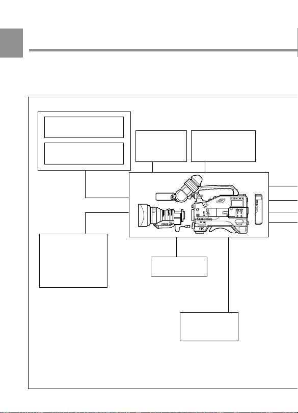
1-2 Example of System
1
Configuration
The diagram below shows a typical configuration of the camcorder for
ENG and EFP.
Viewfinder-related equipment
Fog-proof filter
(Part No. 1-547-341-11)
BKW-401 Viewfinder
Rotation Bracket
Extension
board
HKDW-703 for
picture cache
HKDW-702
converting the signal
to 525i/625i signal
a)
for
BKDW-701
Servo filter unit
Memory stick
Video monitor for
color image check
while shooting
Remote controll
equipment
RM-B150 Remote
Control Unit
a) Be sure to attach the HKDW-702/1 or
higher to the HDW-750CE.
Chapter 1 Overview1-6
Page 19
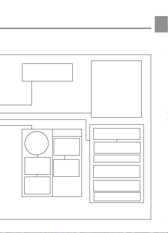
For more information about the fittings, connections, or use of additional
equipment and accessories, see Chapter 5 as well as the operation manuals for
the connected equipment.
1
Camera adaptor
HDCA-901 for the input of
the audio channels 3 and
4 and the HD-SDI output
Power source
Battery
AC power
supply
BC-L120
c)
Battery
Charger
AC-550/
550CE
AC Adaptor
BP-L60A
Battery Pack
AC-DN2B
AC Adaptor
b) For more information, see
“Viewfinder and related equipment”
on page A-7.
c) 120 V AC or 220 to 240 V AC
Lens assembly
(Part No. A-8262-537-A)
Lens assembly
(Part No. A-8262-538-A)
Lens assembly
(Part No. A-8267-737-A)
Lens assembly
b)
(−2.8 D to +2.0 D)
b)
(−3.6 D to −0.8 D)
b)
(−3.6 D to +0.4 D)
b)
(3 × magnification)
(−2.4 D to +0.5 D)
(Part No. A-8314-798-A)
Audio signal source
External microphone
C-74, etc.
CAC-12 Microphone
Holder
Audio equipment
WRR- 810A/860A/862A/
862B UHF Portable Tuner
WRR-855A/855B slotin UHF portable tuner
CCXA-53 audio cable
Chapter 1 Overview 1-7
Page 20

1-3 Precautions
Use and Storage
1
Do not subject the camcorder to severe shocks
The internal mechanism may be damaged or the body warped.
After use
Always turn off the power.
Before storing the camcorder for a long period
Remove the battery pack.
Use and storage locations
Store in a level, ventilated place. Avoid using or storing the camcorder
in the following places.
• Places subject to temperature extremes
• Very damp places
• Places subject to severe vibration
• Near strong magnetic fields
• In direct sunlight or close to heaters for extended periods
To prevent electromagnetic interference from portable
communications devices
The use of portable telephones and other communications devices near
this unit can result in misoperations and interference with audio and
video signals.
It is recommended that the portable communications devices near this
unit be powered off.
Chapter 1 Overview1-8
Page 21
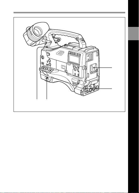
2-1 Power Supply
1
2
43
Power supply
1 Battery attachment
Attach a BP-L60A battery pack.
Furthermore, by attaching an AC-DN2B AC Adaptor, you can operate
the camcorder from AC power.
2
Locations and Functions of Parts and Controls
2 DC IN (external power input) connector (XLR type, 4-pin, male)
To operate the HDW-750/750CE using an AC power supply, connect an
AC-550/550CE AC Adaptor with the DC output cable supplied with the
adaptor.
To use an external battery, connect its DC output cable to the DC IN
connector.
Chapter 2 Locations and Functions of Parts and Controls 2-1
Page 22

3 POWER switch
This switch turns the main power supply on and off.
4 LIGHT switch
2
This switch selects the way in which a video light connected to the
LIGHT connector is switched on and off.
AUTO: When the video light switch is turned on, starting recording with
the VTR turns on the light.
MANUAL: The video light switch controls the light, turning it on and
off manually.
Chapter 2 Locations and Functions of Parts and Controls2-2
Page 23
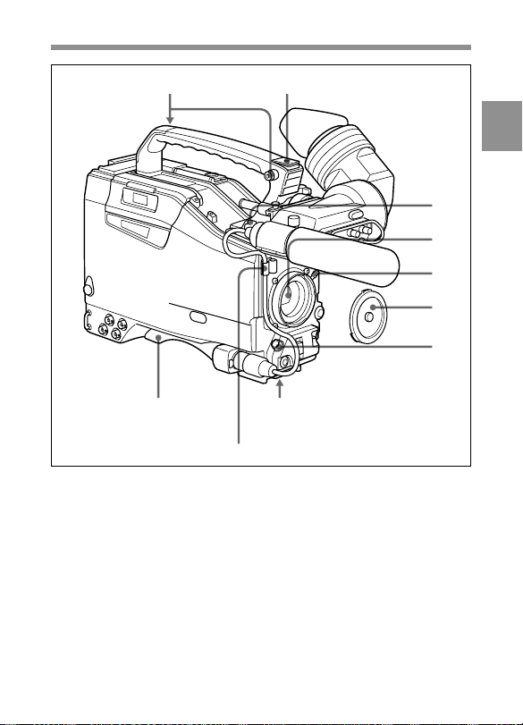
2-2 Accessory Attachments
12
89
Lens cable clamp
Accessory attachments
1 Shoulder strap posts
Attach the supplied shoulder strap to these posts.
2
3
4
5
6
7
2 Light shoe
Attach an optional accessory such as a video light to this shoe.
Chapter 2 Locations and Functions of Parts and Controls 2-3
Page 24

3 LIGHT connector (2-pin, female)
Connect the cable of the Anton Bauer Ultralight System attached to the
light shoe. The system operates with lights powered by 12 V, with a
maximum power consumption of 50 W.
2
4 Lens mount (special bayonet mount)
Use this for mounting the lens.
5 Lens locking lever
After inserting the lens in the lens mount, rotate the lens mount ring with
this lever to lock the lens in position.
6 Lens mount cap
Remove this cap by pushing up on the lens locking lever. For protection
from dust, always insert this cap when no lens is mounted.
7 LENS connector (12-pin)
Fit the lens cable to this connector. Contact your Sony representative for
more information about the lens you are using.
8 Tripod mount
When using the unit on a tripod, attach the supplied tripod adaptor.
9 Shoulder pad
You can move the shoulder pad forwards or backwards by loosening the
two screws. Do this to ensure the best balance when shooting with the
camcorder on your shoulder.
Chapter 2 Locations and Functions of Parts and Controls2-4
Page 25
2-3 Audio Functions
1
2
3
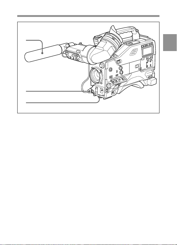
Audio functions (1)
1 Microphone
This is a super-cardioid directional stereo microphone with an external
power supply (+48 V) system.
If you assign the Front MIC MONO/STEREO function to either
ASSIGN 1 or 2 switch, you can switch the monaural and stereo outputs.
2 MIC IN (microphone input) connector (XLR type, 5-pin, female)
You can connect a supplied stereo microphone with an external power
supply system. The connector supplies power (+48 V) to the
microphone.
3 MIC LEVEL knob
This knob adjusts the audio level of the microphone connected to the
MIC IN connector.
2
Chapter 2 Locations and Functions of Parts and Controls 2-5
Page 26
2
ADVANCE SHIFT LEVEL
PRESET
F-RUN
REGEN
SET
CLOCK
R-RUN
MEMORY STICK
OPEN
CUE IN AUDIO IN
DATA DISPLAY
CH-1
U-BIT
MIX
TIME
CH-2
SHOT
NO
100100
F
R
AUTO
W
MANUAL
AUDIO SELECT
CH-1 CH-2 CH-4
WIRELESS
FRONT
F
REAR
R
W
CH-3
4
5
6
7
8
9
q;
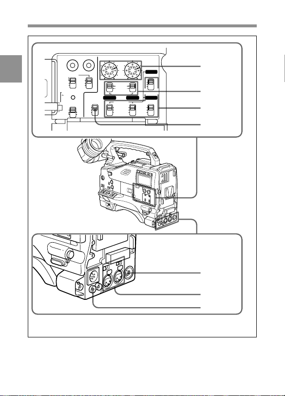
Audio functions (2)
Chapter 2 Locations and Functions of Parts and Controls2-6
Page 27

4 LEVEL (CH-1/CH-2) (audio channel 1 and channel 2 recording
level) controls
These controls adjust the audio levels of channels 1 and 2 when audio
input is from the AUDIO IN CH-1/CH-2 connectors and the AUDIO
SELECT switches are set to MANUAL.
5 AUDIO SELECT (CH-1/CH-2) (audio channel-1 and channel-2
adjustment method select) switches
These switches select the audio level adjustment method for each of
audio channels 1 and 2.
AUTO: Select this setting for automatic adjustment.
MANUAL: Select this setting for manual adjustment.
6 AUDIO IN CH-1/CH-2 / CH-3/CH-4 (audio input select)
switches
AUDIO IN CH-1/CH-2 switches
These switches select the audio input signals to be recorded for audio
channels 1 and 2.
FRONT: The input signal source is the microphone connected to the
MIC IN connector.
REAR: The input signal source is the audio equipment connected to the
AUDIO IN CH-1/CH-2 connectors.
WIRELESS: The input signal source is a WRR-855A/855B UHF
Synthesized Tuner Unit (not supplied).
CH-3/CH-4 switches
These switches select the audio input signals to be recorded for audio
channels 3 and 4.
Note
To activate CH-3/CH-4 switches, set AUDIO CH3/4 MODE to SW on
the VTR MODE 1 page of the MAINTENANCE menu.
F (FRONT): The input signal source is the microphone connected to the
MIC IN connector.
R (REAR): The input signal source is the audio equipment connected to
the AUDIO IN CH-1/CH-2 connectors.
2
Chapter 2 Locations and Functions of Parts and Controls 2-7
Page 28

W (WIRELESS): The input signal source is a WRR-855A/855B UHF
Synthesized Tuner Unit (not supplied).
With the HDCA-901 (not supplied) connected to the camcorder, you can
2
record separate sounds in audio channels 3 and 4.
7 CUE IN (cue track input) switch
This switch selects the input signal to be recorded on the cue track.
CH-1: Signal selected by the AUDIO IN CH-1 switch 6
MIX: Mixed signals selected by the AUDIO IN CH-1 and CH-2
switches 6
CH-2: Signal selected by the AUDIO IN CH-2 switch 6
8 AUDIO OUT (audio output) connector (XLR type, 5-pin, male)
This connector outputs the audio signals recorded to audio channels 1
and 2 or audio channels 3 and 4.
The MONITOR CH-1/2 / CH-3/4 switches qd allow you to select the
audio signal to be played back.
Using a CCXA-53 Audio Cable (not supplied), you can convert from a 5-pin
connection to two 3-pin connections.
9 AUDIO IN CH-1/CH-2 (audio channel 1 and channel 2 input)
connectors (XLR type, 3-pin, female) and LINE/MIC/+48 V ON
(line input/microphone input/external power supply +48 V ON)
switches
These are audio input connectors for channels 1 and 2 to which you can
connect audio equipment or a microphone.
The LINE/MIC/+48V ON switches select the audio source of the audio
input signals connected to each of these connectors.
LINE: Line input audio equipment
MIC: Microphone with an internal power supply
+48V ON: Microphone with an external power supply system
0 DC OUT (DC power output) connector
This connector supplies power for a WRR-810A/860A/862A/862B UHF
Portable Tuner (not supplied). Do not connect any equipment other than
the UHF portable tuner.
Chapter 2 Locations and Functions of Parts and Controls2-8
Page 29
qd qs qa
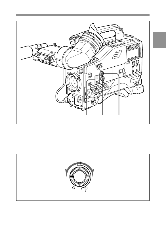
Audio functions (3)
qa ALARM volume control
This control adjusts the speaker or earphone alarm volume. At the
minimum position, no sound can be heard.
ALARM
Minimum Maximum
ALARM volume control
2
Chapter 2 Locations and Functions of Parts and Controls 2-9
Page 30
The internal volume control can be adjusted so that the alarm is audible
even if the ALARM volume control is at the minimum position.
For more information, refer to the Maintenance Manual.
2
qs MONITOR volume control
This control adjusts the speaker or earphone volume for sounds other
than the alarm sound. At the minimum position, no sound can be heard.
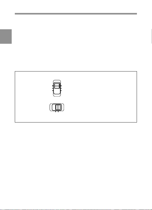
qd MONITOR (audio channel select) switch /CH-1/2 / CH-3/4 (audio
channel 1/2 / audio channel 3/4 select) switch
MONITOR
CH-1
MIX
CH-2
CH-1/2 CH-3/4
MONITOR switch and CH-1/2 / CH-3/4 switch
CH-3
MONITOR switch
MIX
CH-4
CH-1/2 / CH-3/4 switch
CH-1/2 / CH-3/4 switch
This switch decides the audio channel to be selected by the MONITOR
switch.
CH-1/2: Audio channels 1 and 2
CH-3/4: Audio channels 3 and 4
The following settings depend on the CH-1/2 / CH-3/4 switch setting:
• The signal output to the AUDIO OUT connector 8 is switched.
CH-1/2: Audio channels 1 and 2
CH-3/4: Audio channels 3 and 4
• The audio signal indicated by the audio level meter in the display
window is switched.
Chapter 2 Locations and Functions of Parts and Controls2-10
Page 31

MONITOR switch
This switch selects the audio output to the speaker or earphone.
CH-1/2 CH-3/4 MONITOR switch Audio output
position position
CH-1/2 CH-1 Audio channel 1
MIX Mix sound of channels 1 and 2
CH-2 Audio channel 2
CH-3/4 CH-3 Audio channel 3
MIX Mix sound of channels 3 and 4
CH-4 Audio channel 4
2
Chapter 2 Locations and Functions of Parts and Controls 2-11
Page 32

2
qf
qg
Audio functions (4)
qf Built-in speaker
During recording, the speaker can be used for monitoring the E-E
1)
sound, and during playback for monitoring playback sound. The speaker
also sounds alarms to reinforce visual warnings.
If an earphone is plugged into to the EARPHONE jack, the speaker
sound is automatically cut off.
See “6-3 Operation Warnings” on page 6-16 for information about alarms.
....................................................................................................................................
1) E-E sound (Electric-to-Electric sound)
The term E-E sound refers to an audio signal that has passed though the
amplifier, but has not been recorded on the tape. In other words, you can directly
monitor the recording input signal, as opposed to the simultaneous playback
(output) signal.
Chapter 2 Locations and Functions of Parts and Controls2-12
Page 33

qg EARPHONE jacks (minijack)
You can monitor the E-E sound during recording and playback sound
during playback. Plugging an earphone into the jack automatically cuts
off the built-in speaker, and you hear the alarms about the camcorder's
operation and status through the earphone.
The signals output from these jacks are the same. You can connect two
earphones to these jacks at the same time.
2
Chapter 2 Locations and Functions of Parts and Controls 2-13
Page 34

2-4 Shooting and Recording/
Playback Functions
2
1
2
3
4
5
6
9
Shooting and recording/playback functions (1)
1 TALLY indicator
Setting the TALLY switch to HIGH or LOW activates this indicator. The
indicator lights during recording on the VTR. It also provides the same
information as the REC indicator in the viewfinder: it comes on during
recording and flashes to indicate a problem.
78
Eyecup
q;
qa
qs
Chapter 2 Locations and Functions of Parts and Controls2-14
Page 35

2 BRIGHT (brightness) control
This control adjusts the picture brightness on the viewfinder screen. It
has no effect on the camera output signal.
3 CONTRAST control
This control adjusts the picture contrast on the viewfinder screen. It has
no effect on the camera output signal.
4 PEAKING control
This control adjusts the sharpness of the picture on the viewfinder screen
to make focusing easier. It has no effect on the camera output signal.
5 ZEBRA (zebra pattern) switch
This switch controls the zebra pattern on the viewfinder screen.
ON: The zebra pattern 1) is displayed and stays.
OFF: No zebra pattern is displayed.
MOMENT: The zebra pattern is displayed and stays for 5 to 6 seconds.
The zebra pattern is factory set to indicate picture areas where the
video level is approximately 70%. The setup menu can be used to
specify that areas where the video level is 100% and above are to be
displayed at the same time.
For information about how to set the zebra pattern is to be displayed to indicate
areas of 100% or more, see “4-7-5 Setting the Viewfinder” on page 4-77.
....................................................................................................................................
1) Zebra pattern
The zebra pattern aids in manual iris adjustment by indicating areas of the
picture where the video level is approximately 70% and 100% and above.
2
Chapter 2 Locations and Functions of Parts and Controls 2-15
Page 36

6 TALLY switch
This switch controls the TALLY indicator, setting its brightness (HIGH
or LOW) or turning it off.
HIGH: The TALLY indicator gets brighter.
2
OFF: The TALLY indicator does not operate.
LOW: The TALLY indicator gets dimmer.
7 Viewfinder
The viewfinder lets you to view the camera image in black and white
while shooting the picture and also see the playback picture from the
VTR. It also displays various warnings and messages related to the
settings or operating conditions of the camcorder, a zebra pattern, safety
zone marker1), and center marker2).
Also, you can use the BVF-V20/V20CE black and white viewfinder with
the 525i/625i method and BVF-VC10 color viewfinder.
8 Diopter adjustment ring
Use this ring to adjust the viewfinder image for your vision.
9 Viewfinder front-rear positioning lever
Use this lever to move the viewfinder forward or backward.
0 Viewfinder left-right positioning ring
Use this ring to move the viewfinder sideways.
....................................................................................................................................
1) Safety zone marker
The safety zone marker is a rectangle indicating the effective picture area.
For more information, see “4-7-4 Setting the Marker Display” on page 4-74.
2) Center marker
The center marker indicates the center of the picture with a crosshair.
Chapter 2 Locations and Functions of Parts and Controls2-16
Page 37

qa Cameraman tally indicator
This indicator lights while the camcorder is operating.
Slide the window open when you shoot, keeping your eye away from the
viewfinder. This indicator flashes when the battery level is running low
or the tape is nearing its end.
qs Viewfinder stopper
Pull up this stopper to detach the viewfinder from the camera.
2
Chapter 2 Locations and Functions of Parts and Controls 2-17
Page 38

2
qd qf qg qh qj qk ql w;
Shooting and recording/playback functions (2)
qd FILTER selector
This selector is a dual knob that selects the most appropriate filter to
match the light source illuminating the subject. The outer knob selects
the color temperature of the CC (Color Conversion) filter, and the inner
knob selects the type of ND (Neutral Density) filter. The white balance is
stored in memory for each CC filter.
Note that if the display mode is set to 3, when this selector is adjusted,
the new setting will be indicated on the viewfinder screen for about 3
seconds. (e.g.: FILTER: 3)
For detailed information on the display mode, see “4-7-3 Display Mode and
Setting Change and Adjustment Progress Messages” on page 4-72.
Chapter 2 Locations and Functions of Parts and Controls2-18
Page 39

The relationships between the selector settings and filter selections as
well as examples of filters for different shooting conditions are given
below.
FILTER selector (outer) setting and CC filter selection
FILTER selector (outer) setting CC filter selection
A Cross filter
B 3200K
C 4300K
D 6300K
a) A type of special effect filter. Generates a cross-hair light ray on a highlighted
portion.
FILTER selector (inner) setting and ND filter selection
FILTER selector (inner) setting ND filter selection
1 Clear
2 1/4 ND
3 1/16 ND
4 1/64 ND
Examples of shooting conditions and appropriate filters
Shooting condition CC filter ND filter
Sunrise and sunset; B (3200 K) 1 (clear)
inside studio
Clear skies C(4300 K) or 2 (1/4 ND) or
D (6300 K) 3 (1/16 ND)
Cloudy or raining D (6300 K) 1 (clear) or
Very bright conditions C (4300 K) or 3 (1/16 ND) or
such as snow, at high D (6300 K) 4 (1/64 ND)
altitudes, or at the seashore
a)
2 (1/4 ND)
2
Chapter 2 Locations and Functions of Parts and Controls 2-19
Page 40

qf SHUTTER selector
Set this selector to ON to use the electronic shutter. Set it to SEL to
switch the shutter speed or mode setting within the range that has been
previously set from the setup menu.
2
When this selector is adjusted, the new setting will be indicated on the
setting change/adjustment progress message display area for about 3
seconds.
For more information about the shutter speed and mode settings, see “4-2 Setting
the Electronic Shutter” on page 4-12.
qg AUTO W/B BAL (automatic white/black balance adjustment)
switch
This switch activates the white balance and black balance automatic
adjustment functions.
WHT: Automatic adjustment of the white balance. If the WHITE BAL
switch is set to A or B, the white balance setting is stored in the
corresponding memory. The memory can store the white balance
setting for each CC filter.
BLK: Automatic adjustment of the black set and black balance.
qh ASSIGN (assignable) switches 1/2
You can assign the desired functions to each of ASSIGN 1 switch (pushtype) and ASSIGN 2 switch (slide-type) on the FUNCTION 1 page of
the USER menu.
For details, see “4-8-5 Assigning Functions to ASSIGN 1/2 Switches” on page 4-
108.
qj GAIN selector
This selector switches the gain of the video amplifier to match the
lighting conditions during shooting. The gains corresponding to the L,
M, and H settings are selected from the setup menu before use. The
factory settings are L = 0 dB, M = 6 dB, and H = 12 dB.
When this selector is adjusted, the new setting will be indicated on the
Chapter 2 Locations and Functions of Parts and Controls2-20
Page 41

setting change/adjustment progress message display area of the
viewfinder screen for about 3 seconds.
For information about setting the gain values, see “4-8-1 Setting the GAIN Selector
Values” on page 4-97.
qk OUTPUT/DCC (output signal/dynamic contrast control) selector
This selector switches the video signal that is output to the VTR,
viewfinder, and video monitor, between the color bar signal and the
camera output.
BARS: Outputs the color bar signal.
CAM: Outputs the camera signal. It also switches DCC1) on and off
when output from the camera is selected.
BARS, DCC OFF
A color bar signal is output and the DCC
circuit does not operate. For example, use
the setting for the following purposes.
• Adjusting the video monitor
• Recording the color bar signal
OUTPUT
BARS•CAM
•
•
•
OFF
ON
DCC
....................................................................................................................................
1) DCC (Dynamic Contrast Control)
Also called automatic knee. Against a very bright background with the iris
opening adjusted to the subject, objects in the background will be lost in the
glare. The DCC function will suppress the high intensity and restore much of the
lost detail and is particularly effective in the following cases.
• Shooting a subject against a bright sky
• Shooting a subject indoors, against a background through a window
• Any high contrast scenes
Chapter 2 Locations and Functions of Parts and Controls 2-21
CAM, DCC OFF
The video signal from the camera is
output, and the DCC circuit does not
operate.
CAM, DCC ON
The video signal from the camera is
output, and the DCC circuit operates.
OUTPUT/DCC selector
2
Page 42

ql WHITE BAL (white balance memory) switch
This switch determines the source of the white balance settings.
PRST (preset): Adjusts the color temperature corresponding to the
2
position of the FILTER selector (outer knob). Use the PRST setting
when you have no time to adjust the white balance.
A or B: When the AUTO W/B BAL switch is pushed to WHT, the white
balance is automatically adjusted according to the current position of
the FILTER selector (outer knob), and the adjusted value is stored in
either memory A or memory B. (There are two memories for each
CC filter, so a total of eight adjustments can be stored.) When the
FILTER selector (outer knob) is at the same position as it was when
this WHITE BAL switch was adjusted, the stored value is called from
memory, and the camcorder automatically adjusts itself to that value.
B (ATW): When this switch is set to B whereas, on the FUNCTION 2
page of the OPERATION menu, WHITE B CH is set to ATW
ATW is activated.
When this switch is adjusted, the new setting will be indicated on the
setting change/adjustment progress message display area of the
viewfinder screen for about 3 seconds.
You can assign the ATW ON/OFF function to the ASSIGN 1 switch
(push-type) on the FUNCTION 1 page of the USER menu.
For details, see “4-8-5 Assigning Functions to ASSIGN 1/2 Switches” on page 4-
108.
w; TURBO GAIN button
When shooting under extremely poor lighting conditions, slide the cover
of this button to the left and press the button once to boost the video gain
to the value preset on the GAIN SW page of the USER menu (up to 42
dB, factory setting: 42 dB). To stop boosting the gain, press the button
once more.
1)
, the
....................................................................................................................................
1) ATW (Auto Tracing White Balance)
The white balance of the picture being shot is adjusted automatically for the
varying lighting conditions.
Chapter 2 Locations and Functions of Parts and Controls2-22
Page 43

wa ws wd wf wg
Shooting and recording/playback functions (3)
wa VBS/SDI OUT (video signal output) connector (BNC type)
(Only when the HKDW-702 extension board (not supplied) is
installed)
In this manual, the illustration of the camcorder which the BNC
connector is attached is used. If you do not install the HKDW-702,
ignore this connector.
This connector outputs down-converted 525i/625i signals (75-ohm
terminated) to the video monitor. The output signal can be selected as
analog composite or SDI. Refer to the FUNCTION 1 page of the USER
menu. Selecting OFF stops the converter.
For instructions on how to select the output signal, see “4-8-2 Selecting the Output
Signals” on page 4-100.
2
Chapter 2 Locations and Functions of Parts and Controls 2-23
Page 44

Note
• The down-converted signal (analog composite/SDI signals) is delayed
by several milliseconds, compared with the video signal recorded on
the tape.
2
• When the HKDW-702 is attached to the HDW-750, the HD signal is
down-converted to the 525i signal. When the HKDW-702 is attached
to the HDW-750CE, the HD signal is down-converted to the 625i
signal.
ws HD SDI OUT (HD SDI output) connector (BNC type)
This connector outputs the HD SDI signal to the video monitor.
For instructions on how to select whether or not the signal is output from
this connector (ON/OFF), refer to the OUTPUT SEL page of the USER
menu.
For details, see “4-8-2 Selecting the Output Signals” on page 4-100.
wd REMOTE (remote control) connector (8-pin)
Connect the RM-B150 Remote Control Unit (not supplied), which makes
VTR control possible.
wf TEST OUT (test output) connector (BNC type)
This connector outputs the HD-Y (black and white) signal.
When the HKDW-702 extension board (not supplied) is installed, the
output signal can be selected as a down-converted analog composite
(color) or HD-Y signal on the OUTPUT SEL page of the USER menu.
Depending on the internal board and menu settings, the menu, time code,
and shot data can be displayed over the image on the monitor. You can
use this connector to synchronize the time code of an external VTR to
the time code of the camcorder.
For instructions on how to select the test output signal when the HKDW-702 is
installed, see “4-8-2 Selecting the Output Signals” on page 4-100.
Chapter 2 Locations and Functions of Parts and Controls2-24
Page 45

wg GENLOCK IN (genlock input) connector (BNC type)
This connector inputs an HD reference signal when the camera is to be
genlocked or when the time code is to be synchronized with external
equipment. Use the MAINTENANCE menu to adjust the genlock Hphase (phase of Horizontal sync signal).
For details, refer to the Maintenance Manual.
This connector also inputs the NTSC/PAL composite video signal as the
reference signal when the time code is to be synchronized with external
equipment. In this case, the genlock H-phase cannot be adjusted. Beyond
that, the subcarrier of the down-converted signal (composite video
signal) cannot be synchronized with external equipment when the
HKDW-702 (not supplied) is installed.
2
Chapter 2 Locations and Functions of Parts and Controls 2-25
Page 46

2
wh
wj
wk
wl
D
F FW
REW
EJECT
Shooting and recording/playback functions (4)
PLAY
STOP
Opening the cover
Press on the tab.
wh VTR START button
Press this button to start recording. Press it again to stop recording. The
effect is exactly the same as that of the VTR button on the lens.
When the REC BUTTON function is assigned to the ASSIGN 1 (push
type), you can use the ASSIGN 1 switch as the VTR START button.
Chapter 2 Locations and Functions of Parts and Controls2-26
e;
ea
es
1
2
Page 47

wj VTR SAVE/STBY (VTR power saving/standby) switch
This switch controls the VTR power mode during pauses in recording
(REC PAUSE).
SAVE: Power saving mode. When you press the VTR START button,
there is a short delay before recording starts, but power consumption
is less than in standby mode, and battery life is extended. When the
switch is set to SAVE, the VTR SAVE indicator in the viewfinder
lights.
STBY: Standby mode. Recording starts as soon as you press the VTR
START button. Avoid allowing the camcorder to remain in STBY
(standby) mode for a long time.
wk EJECT (cassette eject) button
Press this button to eject or load a cassette.
wl REW (rewind) button and indicator
Press this button to rewind the tape. The indicator lights during
rewinding.
e; F FWD (fast forward) button and indicator
Press this button to fast forward the tape. The indicator lights during fast
forward.
ea PLAY (playback) button and indicator
Press this button to view the recorded picture in the viewfinder or on the
color video monitor. The indicator lights during playback.
The 4 times normal speed search function is provided to make it far
quicker to find a desired location of the tape. Press the REW button or F
FWD button during playback to view the 4 times normal speed search
picture.
2
es STOP button
Press this button to stop the tape.
Chapter 2 Locations and Functions of Parts and Controls 2-27
Page 48

2-5 Menu Operating Section
2
1
2
CANCEL/PRST
ON/SEL
STATUS
OFF
Chapter 2 Locations and Functions of Parts and Controls2-28
3
Menu operating section
OFF
ON ESCAPE
MENU
4
5
Page 49

1 Memory stick compartment
MEMORY STICK OPEN button
EJECT button
Memory stick
Open the cover of the memory stick compartment by pressing the
MEMORY STICK OPEN button. Insert the memory stick (not supplied)
with the notch facing downward and the label facing toward you into the
slot.
2
Chapter 2 Locations and Functions of Parts and Controls 2-29
Page 50

2 MENU knob
Use this knob to change the page selection or a setting within the menu.
Push: If you push this knob when the arrow (t) is placed at the page
2
title on the menu, the arrow (t) changes to the question mark (?)
and you can change the page.
When the arrow mark is placed at the position other than the page
title, the camcorder turns in mode where you can change the settings
by pushing this knob.
Turn: Turn this knob to change the page or change the settings of the
items.
3 STATUS ON/SEL / OFF (menu display on/paging/display off)
switch
To enable this switch, set the MENU ON/OFF switch to OFF.
Closing the cover automatically sets the MENU ON/OFF switch to OFF.
ON/SEL: Each time this switch is pushed upward, the window to
confirm the menu settings and conditions of the camcorder is
displayed on the viewfinder screen. There are three windows, which
are switched each time the switch is pushed upward. Each window is
displayed for about 10 seconds.
OFF: To clear the page immediately after display, push this switch down
to the OFF position.
You can select the confirmation window to be displayed on the
menu.
For details, see “Display/don’t display status confirmation windows” on page 4-
91.
Chapter 2 Locations and Functions of Parts and Controls2-30
Page 51

4 MENU ON/OFF (menu display) switch
To use this switch, open the cover.
This switch is used to display the menu on the viewfinder screen or the
test signal screen. Closing the cover results in automatically setting this
switch to OFF.
ON: Displays the menu on the viewfinder screen or the test signal
screen, at the page which was on the screen when the previous menu
access ended. (When the menu is first used, the first page is
displayed.)
OFF: Removes the menu from the viewfinder screen or the test signal
screen.
5 CANCEL/PRST / ESCAPE (menu setting cancellation/menu
presetting/returning page) switch
To enable this switch, set the MENU ON/OFF switch to ON.
Closing the cover automatically sets the MENU ON/OFF switch to OFF.
CANCEL/PRST: Pushing this switch up to this position displays the
message to confirm whether the previous settings are cancelled or
settings are reset to their initial values, depending on the menu
operating condition.
Pushing this switch up to this position again cancels the previous
settings or resets the settings to their initial values.
ESCAPE: Use this switch when the menu page, which has a hierarchical
structure, is opened. Each time the switch is pushed to this position,
the page returns to one stage higher in the hierarchy.
2
Chapter 2 Locations and Functions of Parts and Controls 2-31
Page 52

2-6 Time Code System
2
1
2
3
Time code functions (1)
1 GENLOCK IN (genlock input) connector (BNC type)
• This connector inputs an HD reference signal when the camera is to be
genlocked or when the time code is to be synchronized with external
equipment.
This connector can input an NTSC/PAL analog composite signal as the
reference video signal when the time code is to be synchronized with
external equipment.
Chapter 2 Locations and Functions of Parts and Controls2-32
Page 53

• This connector also inputs a return video signal. You can display the
image of the return video signal in the viewfinder screen when you set
the RETURN VIDEO to ON on the GENLOCK page of the
OPERATION menu.
You can assign the RETURN VIDEO function to ASSIGN 1 switch.
For details, see “4-8-5 Assigning Functions to ASSIGN 1/2 Switches” on page 4-
108.
2 TC IN (time code input) connector (BNC type)
To synchronize the time code with an external time code, connect the
reference time code input here.
3 TC OUT (time code output) connector (BNC type)
To synchronize the time code of an external VTR with that of the
camcorder, connect this connector to the time code input lock connector
of the external VTR.
2
Chapter 2 Locations and Functions of Parts and Controls 2-33
Page 54

2
4
HOLD RESET DISPLAY LIGHT WARNING
OFF ONTCCTL DATA
5
6
7
8
9
q;
qa
Chapter 2 Locations and Functions of Parts and Controls2-34
ADVANCE SHIFT LEVEL
PRESET
F-RUN
REGEN
SET
CLOCK
R-RUN
MEMORY STICK
OPEN
DATA DISPLAY
U-BIT
SHOT
TIME
NO
AUDIO SELECT
CH-1 CH-2 CH-4
CUE IN AUDIO IN
CH-1
MIX
CH-2
Time code functions (2)
100100
AUTO
MANUAL
FRONT
REAR
WIRELESS
CH-3
F
R
W
F
R
W
Page 55

4 HOLD (display hold) button
Pressing this button instantly freezes the time data displayed in the
counter display section. (The time code generator continues normal
operation.) Pressing this button again releases the hold. One use of this
feature is to determine the exact time of a particular shot.
When the HOLD button is activated, the time data is displayed in the
following format:
See “2-8 Warnings and Indications on the Display Panel” on page 2-41 for more
information about the counter display.
5 RESET (counter reset) button
This button resets the time data displayed on the counter display section
to “00:00:00:00” and the user bit data to “00000000".
6 DISPLAY (LCD) switch
CTL: Control signal
TC: Time code
DATA: The item selected by the DATA DISPLAY switch.
For more information, see “Time code displays” on page 2-43.
7 ADVANCE button
For setting the time code, user bits, or real time, each press of this button
increments the flashing digit selected by the SHIFT button.
8 SHIFT button
For setting the time code, user bits, or real time, this button selects the
digit to be changed. The selected digit flashes.
2
Chapter 2 Locations and Functions of Parts and Controls 2-35
Page 56

9 PRESET/REGEN/CLOCK (preset/regeneration/clock) switch
This switch selects whether to set a new time code or to match the
existing time code that had been recorded.
PRESET: Starts recording time code values on the tape from the newly
2
set value.
REGEN: Reads the existing time code on the tape and sets the time code
starting value accordingly. Thus, even when there is an indefinite
break in recording, this setting ensures that time codes on the tape
will be continuous. Regardless of the setting of the F-RUN/SET/RRUN switch, the camcorder operates in R-RUN mode.
CLOCK: Makes the time code value coincide with the built-in clock.
Regardless of the F-RUN/SET/R-RUN switch setting, the camcorder
always operates in F-RUN mode.
For more information, see “To make the time code continuous” on page 4-36.
0 F-RUN/SET/R-RUN (free run/set/recording run) switch
This switch selects the operating mode for the internal time code
generator.
F-RUN: The time code generator keeps running, regardless of the
operation state of the VTR. Use this position when matching the time
code to real time or for synchronizing the time code with an external
time code.
SET: Set the switch to this position to set the time code or user bits.
R-RUN: The time code generator runs only while recording. This
produces a tape with consecutive time code value, even when shot
intermittently.
For more information, see “4-5-3 Setting the User Bits” on page 4-37 and “4-5-1
Setting the Time Code” on page 4-34.
Chapter 2 Locations and Functions of Parts and Controls2-36
Page 57

qa DATA DISPLAY switch
U-BIT: Display the user bit value.
SHOT-TIME: Display the date and time from the shot data.
SHOT-NO: Display the shot number from the shot data.
2
Chapter 2 Locations and Functions of Parts and Controls 2-37
Page 58

2-7 Warnings and Indications
The camcorder supplies you visual information and warnings by means
of its indicators without you having to use the speaker, earphone or
viewfinder.
2
1
2
3
4
5
6
7
8
9
Warning and indication functions
Chapter 2 Locations and Functions of Parts and Controls2-38
Page 59

1 TALLY indicator
Setting the TALLY switch to HIGH or LOW activates this indicator. The
indicator lights during recording on the VTR. It also provides the same
information as the REC indicator in the viewfinder; it lights up during
recording and flashes to indicate a problem. The brightness of this
indicator when it is lit can be controlled by the TALLY switch.
2 DISPLAY/ASPECT (display/aspect control) switch
Use this switch to turn the markers on or off and to change the
viewfinder screen aspect ratio.
DISPLAY: When the MARKER is set to ON on the MARKER 1 page
of the USER menu, pushing this switch to DISPLAY toggles the
markers on the viewfinder screen on and off.
Even if the DISPLAY switch is set to OFF, the USER menu appears
by setting the MENU ON/OFF switch is set to ON.
ASPECT: Pushing this witch to ASPECT toggles the viewfinder screen
aspect ratio between 16 : 9 and 4 : 3.
For details, see “4-7-4 Setting the Marker Display” on page 4-74.
3 TALLY switch
This switch controls the TALLY indicator, setting its brightness (HIGH
or LOW) or turning it off.
HIGH: The TALLY indicator gets brighter.
OFF: The TALLY indicator does not operate.
LOW: The TALLY indicator gets dimmer.
4 BACK TALLY indicator
This indicator is identical to the TALLY indicator 1 when the BACK
TALLY switch 5 is set to ON. (This indicator may not work in the
same manner as the TALLY indicator 1 according to a certain
condition.)
2
Chapter 2 Locations and Functions of Parts and Controls 2-39
Page 60

5 BACK TALLY switch
This switch turns the BACK TALLY and the REAR TALLY indicators
on and off.
ON: Switches on the BACK TALLY and REAR TALLY indicators.
2
OFF: Switches off the BACK TALLY and REAR TALLY indicators.
6 LIGHT switch
This switch controls the display panel light.
ON: Turns the panel light on.
OFF: Turns the panel light off.
7 WARNING indicator
This indicator lights up or flashes when there is a fault in the VTR.
See “6-3 Operation Warnings” on page 6-16 for more information about the
relationships between the operation of the indicator and the meanings of the
indications.
8 Display panel
VTR error messages, battery status, tape status, audio level, time data,
and so forth are displayed on this panel.
For more information, see “2-8 Warnings and Indications on the Display Panel”
on page 2-41.
9 REAR TALLY indicator
This indicator is identical to the BACK TALLY indicator 4 when the
BACK TALLY switch is set to ON.
Chapter 2 Locations and Functions of Parts and Controls2-40
Page 61

2-8 Warnings and Indications
on the Display Panel
Tape status, battery status, and level indicators
Audio channel level meter: When the CH-1/2 / CH-3/4 switch is
set to CH-1/2, the audio channel level 1 is displayed.
When the CH-1/2 / CH-3/4 switch is set to CH-3/4, the audio
channel level 3 is displayed.
H MIN SEC FRM
TAPE E B
BATT E F
RF SERVO HUMID SLACK
Battery status indicator
BATT E F
Nearly dead: “BATT” flashes.
Dead battery (battery must be charged):
“BATT” and “E” flash.
Tape status indicator
TAPE E B
Audio channel level meter:
OVER
EMPH
HOLDPB VITC NDF EXT-LK
OVER
0
V
10
H
20
30
40
PEAK dB
When the CH-1/2 / CH-3/4
switch is set to CH-1/2, the
audio channel level 2 is
displayed.
When the CH-1/2 / CH-3/4
switch is set to CH-3/4, the
audio channel level 4 is
displayed.
Fully charged
2
Full (at beginning)
Close to end: “TAPE” flashes.
End (tape must be replaced):
“TAPE” and “E” flash.
Tape status, battery status, and level indicators
Chapter 2 Locations and Functions of Parts and Controls 2-41
Page 62

VTR operation and status indicators
2
Lights during playback.
H MIN SEC FRM
TAPE E B
BATT E F
RF SERVO HUMID SLACK
OVER
HOLDPB VITC NDF EXT-LK
Warning indicators
RF: Lights if the recording heads are clogged.
SERVO: Lights if the servo motor fails.
HUMID: Lights if condensation is on the drum.
SLACK: Lights if the tape is not winding properly.
For more information, see “6-3 Operation Warnings” on page 6-16.
VTR operation and status indicators
Note
If the tape in the VTR becomes slackened, an error code appears
automatically on the display section of the display panel.
For more information refer to the Maintenance Manual.
EMPH
PEAK dB
OVER
0
10
20
30
40
Chapter 2 Locations and Functions of Parts and Controls2-42
Page 63

Time code displays
Lights in playback mode.
Lights when VITC is selected for the time code.
Lights in non-drop frame mode. (HDW-750 only)
Lights when the camcorder is synchronized with
an external time code.
Lights when the time code
generator is on hold.
OVER
EMPH
HOLDPB VITC NDF EXT-LK
H MIN SEC FRM
TAPE E B
BATT E F
RF SERVO HUMID SLACK
OVER
0
V
10
H
20
30
40
PEAK dB
Lights when the time code, CTL, or
real time is displayed.
Lights in the following way when the HOLD button
is pressed.
Time counter display: Shows the time code, CTL, user bits,
and real time.
The table on the next page lists the details of the displayed
items and switch settings.
2
Time code displays
Chapter 2 Locations and Functions of Parts and Controls 2-43
Page 64

Relationships between the DISPLAY switch and DATA
DISPLAY switch settings and the time counter displays
Except during setting of the time code, the time counter display is
determined by the position of the DISPLAY switch and DATA
2
DISPLAY switch.
For details of setting the time code menu operation, see “4-5-1 Setting the Time
Code” on page 4-34.
Switch settings related to time code and displayed information
DISPLAY DATA DISPLAY Displayed
switch position switch position information
CTL Any position CTL
TC Any position Time code
DATA U-BIT User bits
SHOT-TIME Data and time from shot data
SHOT-NO. Shot number from shot data
Chapter 2 Locations and Functions of Parts and Controls2-44
Page 65

2-9 Indicators on the
Viewfinder
1
2
TALLY/REC
Indicators on the Viewfinder
1 TALLY indicator
This indicator lights when the camcorder is in Loop Rec mode. Also, this
indicator blinks when the camcorder is in auto Interval Rec mode or
manual Interval Rec mode.
2 REC (recording) indicator
This indicator lights in red during recording. It also warns by flashing.
For more information, see “6-3 Operation Warnings” on page 6-16.
BATT
VTR
SAVE
3
Viewefinder
screen
4
5
2
Chapter 2 Locations and Functions of Parts and Controls 2-45
Page 66

3 BATT (battery) indicator
This indicator starts flashing when the battery connected to the
camcorder has fallen, and stays lit when the battery is exhausted.
2
To prevent interruption during operation, replace the battery as soon as
this indicator starts flashing.
The level at which the indicator starts flashing can be set on the
BATTERY page of the MAINTENANCE menu.
For details, see the Maintenance Manual.
6 (warning) indicator
This indicator lights up when the camcorder is used under one or more of
the following conditions and if the corresponding items have been set to
ON on the ‘!’ LED page of the USER menu.
• The gain is set to anything but 0 dB.
• The SHUTTER selector is ON.
• The WHITE BAL switch is set to PRST.
• ATW is being used.
• The lens extender is used.
• The FILTER selector is set to anything but ND:1/CC:A.
• The reference value of the auto iris adjustment is anything but the
standard value.
5 VTR SAVE indicator
Lights up when the VTR section is set to power save mode by setting the
VTR SAVE/STBY switch to SAVE.
Chapter 2 Locations and Functions of Parts and Controls2-46
Page 67

3-1 About Cassettes
This section describes the procedure for loading and unloading a
cassette.
See “Specifications VTR Section ”(page A-3) for information about the cassettes
you can use in the camcorder.
3-1-1 Loading and Unloading a Cassette
Loading a cassette
1 Turn on the POWER switch.
POWER switch
HUMID display
Note
If the interior of the VTR section is damp, the HUMID indicator will
light. If this happens, wait until the indicator goes off before going
on to step 2.
3
Recording and Playback
(Continued)
Chapter 3 Recording and Playback 3-1
Page 68

2 Press the EJECT button.
The cassette lid will open.
Cassette lid
3
3 Check that there is no slack in the tape. Then slide in the cassette
until it clicks into position and close the cassette lid completely by
pressing near the engraved “PUSH".
Insert the cassette.
1
Window
outward.
Cassette holder
Chapter 3 Recording and Playback3-2
2
Push and close the
cassette lid.
Page 69

Notes
• To insert the tape correctly, make sure to stand the grip of the
camcorder.
• When inserting the tape, be careful that you don’t hit the tape against
the tape holder.
Checking the tape for slack
Pressing in the reels lightly, turn them gently with your fingers in the
directions shown below. If the reels will not move, there is no slack.
Checking the tape for slack
Unloading a cassette
With the power supply on, press the EJECT button to open the cassette
lid. Then take out the cassette. If you are not going to insert another
cassette, close the cassette lid.
It is possible to take out the cassette and close the cassette lid unless the
battery voltage drops below about 10.5 V. Do not repeat this unloading
operation.
Chapter 3 Recording and Playback 3-3
3
Page 70

Unloading a cassette manually
If the battery voltage drops below about 10.5 V, take out the cassette
manually as illustrated below.
3
Cassette lid
1 Turn the power off.
2 Open this rubber cover.
3 Pushing on the screw inside
with a screwdriver, turn
the screw clockwise until the
cassette lid opens.
Unloading a cassette manually
You need not return the screw to its original position after taking out the
cassette. Although the cassette lid is not locked, turning on the power
makes the cassette lid operable again.
Chapter 3 Recording and Playback3-4
Page 71

3-1-2 Preventing Accidental Erasure
The following procedure prevents cassettes from being recorded
inadvertently.
Push the plug in. To
reuse the cassette,
return the plug to its
original position.
Preventing accidental erasure
Chapter 3 Recording and Playback 3-5
3
Page 72

3-2 Recording
3-2-1 Basic Procedure
This section describes the basic procedure for shooting and recording.
Before a shooting session, ensure that the camcorder is functioning
properly.
For more information, see ”6-1 Testing the Camcorder Before Shooting” on page
6-1.
3
Turning on the camcorder and loading a cassette
Follow the procedure below.
2
Basic procedure for shooting : from power supply to cassette loading
1 Attach a fully charged battery pack.
For details, see “5-1 Power Supply” on page 5-1.
3
4
1
2
Chapter 3 Recording and Playback3-6
Page 73

2 Set the POWER switch to ON. Check that the HUMID indicator
does not appear and that the BATT indicator shows at least five
segments.
• If HUMID indicator appears, wait until it disappears.
Note
After turning off the power, check whether the drum is dry (even if
the HUMID indicator is off) when the turning on the power again.
• If the BATT indicator does not show at least five segments,
replace the battery pack with a fully charged one.
3 Check that there are no obstructions near the cassette lid. Then press
the EJECT button to open the cassette lid.
4 After checking the points below, load the cassette and close the
cassette lid.
• The cassette is not write-protected.
• There is no slack in the tape.
3
Chapter 3 Recording and Playback 3-7
Page 74

Basic procedure for shooting: from adjusting the
black balance and white balance to stopping recording
After turning on the power and loading a cassette, set the switches and
selectors as shown below and begin operation.
3
Iris:
Automatic
Zoom:
Automatic
DISPLAY: ON
OUTPUT/DCC:
CAM, DCC ON
Switch and selector settings before shooting
F-RUN/SET/R-RUN:
F-RUN or R-RUN
(set as needed)
AUDIO SELECT
CH-1/CH-2:
AUTO
Chapter 3 Recording and Playback3-8
Page 75

Shooting
Follow the procedure below.
1,2
3,5
2
4
5,6
Basic procedure for shooting: from adjusting the black balance and white
balance to stopping recording
1 Push the AUTO W/B BAL switch to BLK to adjust the black
balance.
For detailed information on how to adjust the black balance, see “4-1-1
Adjusting the Black Balance” on page 4-2.
(Continued)
Chapter 3 Recording and Playback 3-9
3
Page 76

2 Select the CC filter and ND filter to match the lighting conditions,
and adjust the white balance.
When the black balance and white balance settings are already
in memory:
Set the WHITE BAL switch to A or B.
3
When the white balance setting is not in memory and you do not
have enough time to adjust the white balance:
Set the WHITE BAL switch to the PRST position. The white
balance is automatically set to 3200 K when the FILTER selector is
set to B, to 4300 K when the FILTER selector is set to C, and to
6300 K when the FILTER selector is set to D.
For more information, see “4-1-2 Adjusting the White Balance”
on page 4-6.
3 Aim the camera at the subject and adjust the focus and zoom.
4 If necessary, set the electronic shutter for an appropriate mode and
speed.
For more information, see ”4-2 Setting the Electronic Shutter”
on page 4-12.
5 To start recording, press the VTR START button or the VTR button
on the lens.
Or if the REC BUTTON function is assigned to the ASSIGN 1
switch, this switch functions as VTR START/STOP buttons.
For details, see “4-8-5 Assigning Functions to ASSIGN 1/2 Switches” on page
4-108.
During recording, the REC indicator in the viewfinder goes on.
Perform zooming and focus control, if necessary.
Chapter 3 Recording and Playback3-10
Page 77

6 To stop recording, press the VTR START button or the VTR button
on the lens again.
The REC indicator in the viewfinder goes off.
Cassette control buttons
During recording, the cassette control buttons (EJECT, REW, F FWD,
PLAY, STOP) have no effect.
3
Chapter 3 Recording and Playback 3-11
Page 78

3-2-2 Continuous Recording
If the camcorder is in the recording pause mode, simply pressing the
VTR START button on the camcorder or the VTR button on the lens
continues recording at exactly the next frame.
In other cases, you first need to position the tape at an appropriate point.
3
When the camcorder is in the recording pause mode
Pressing the VTR START button on the camcorder or the VTR button on
the lens positions the tape at the appropriate point automatically.
However, the time taken before recording starts depends on the setting of
the VTR SAVE/STBY switch.
• If the VTR SAVE/STBY switch is in the SAVE position, it takes about
4 seconds before recording starts.
• If the VTR SAVE/STBY switch is in the STBY position, recording
starts immediately. However, just after the switch position is changed
from SAVE to STBY, it takes about 4 seconds before recording starts.
Chapter 3 Recording and Playback3-12
Page 79

If you turn off the power during a recording pause
2
1
3
Continuous recording after turning off the power during a recording pause
1 Turn on the power again.
2 Press the RET button on the lens.
The camcorder positions the tape at the appropriate point. Note,
however, that this function works only for continuously recorded
material or consecutively joined segments totaling at least 3 seconds
in length.
3 Press the VTR START button on the camcorder or the VTR button
on the lens to start recording.
3
Chapter 3 Recording and Playback 3-13
Page 80

Continuous recording in other cases
After rewinding or fast forward, after removing the cassette, or on a tape
that has been partially recorded, you can obtain a continuous recording
by following the procedure below.
The End Search function also allows you to continue recording on the
partially recorded tape.
3
For details, see “3-2-8 Searching for the Last Recorded Portion and Turning in the
Recording Pause Mode (End Search Function)” on page 3-45.
3
1,2
4
Continuous recording after rewinding or fast forward, after removing the
cassette, or on a tape that has been partly recorded
1 Looking in the viewfinder, press the PLAY button to start playback.
2 Press the STOP button at the desired point to begin recording. To
continue from the end of recording already on the tape, press the
STOP button immediately after the end of the previous recording
(within 0.5 seconds).
3 Press the RET button.
The tape will rewind and will be positioned at the desired point to
continue recording.
4 Press the VTR START button on the camcorder or the VTR button
on the lens to start recording.
Chapter 3 Recording and Playback3-14
Page 81

3-2-3 Recording Good Shot Markers
Good shot markers 1 and 2 are recorded to tape when the RET button on
the lens is pressed during recording.
Recording shot markers
1)
1 and 2 for scenes containing important
images and sounds enables quick access to the marked points. This
increases editing efficiency.
For detailed information on shot marker operations, refer to the manual supplied
with your VTR.
A setting on the VTR MODE 5 page of the MAINTENANCE menu
determines whether or not good shot markers are recorded.
Recording markers to the tape
The VTR MODE 5 page of the MAINTENANCE menu allows you to
decide whether or not markers such as good shot markers and/or
recording start markers are recorded to the tape.
1 Set the MENU ON/OFF switch to ON while pushing the MENU
knob .
The TOP menu appears.
<TOP MENU>
,
USER
USER MENU CUSTOMIZE
ALL
OPERATION
PAINT
MANTENANCE
FILE
DIAGNOSIS
3
....................................................................................................................................
1) Shot marker
(Continued)
Time code of the scene to be used as the editing point when editing.
Chapter 3 Recording and Playback 3-15
Page 82

2 Turn the MENU knob to move the t mark to MAINTENANCE.
3 Push the MENU knob.
When the MAINTENANCE menu is first used, the CONTENTS
page appears.
3
Or if you have used the MAINTENANCE menu already, the page
that was on the screen when the last FILE menu operation ended
appears on the viewfinder screen.
4 When the CONTENTS page is displayed, turn the MENU knob to
move the t mark to VTR MODE 5, then push the MENU knob.
The VTR MODE 5 page appears.
5 Turn the MENU knob to move the t mark to LTC UB-MARKER.
Chapter 3 Recording and Playback3-16
Page 83

6 Push the MENU knob.
The t mark at the left of LTC UB-MARKER changes to the z
mark and the z mark at the left of the setting changes to the ? mark.
7 Turn the MENU knob clockwise or counterclockwise until the
desired setting appears.
The setting changes in order of SET y ALL y OFF.
Item Contents
SET Determines whether or not markers are recorded for the
items REC START MARK, SHOT MARKER 1 and
SHOT MARKER 2 which appear when you select SET.
ALL Records the recording start markers, good shot marker
1 and good shot maker 2.
OFF Does not record any markers.
3
When you select SET, go to step 8.
When you select ALL or OFF, go to step 9.
Chapter 3 Recording and Playback 3-17
(Continued)
Page 84

8 Set the marker(s) to be recorded to ON.
1 Turn the MENU knob to move the t mark to the marker to be
set.
3
2 Turn the MENU knob clockwise or counter clockwise until the
desired setting appears.
To record the marker to the tape, select ON.
To not record the marker, select OFF.
3 Perform settings of the remaining markers repeating steps 1 and
2.
9 Set the MENU ON/OFF switch to OFF to end the menu operation.
Recording a shot marker 1
Press the RET button once. On the viewfinder screen, “z” and the time
code of the marked point are displayed for about 3 seconds.
Recording a shot marker 2
Press the RET button twice. On the viewfinder screen, “X” and the time
code of the marked point are displayed for about 3 seconds.
Chapter 3 Recording and Playback3-18
Page 85

3-2-4 Recording a Recording Start Marker
You can record a recording start marker at the beginning of the
recording.
Using recording start markers enables quick access to the marked points,
for efficient editing.
For detailed information on recording start marker operations, refer to the manual
supplied with your VTR.
You can set whether or not recording start markers are recorded using
the VTR MODE 5 page of the MAINTENANCE menu.
For detailed information on setting whether or not recording start markers are
recorded, see “Recording markers to the tape” on page 3-15.
3-2-5 Starting a Shoot with a Few Seconds of
Pre-Stored Picture Data (Loop Rec
Function) (When Using an HKDW-703
Extension Board)
By installing the optional HKDW-703 extension board (not supplied) in
the camcorder, the camcorder is able to constantly store a few seconds
(up to 7 seconds for the 59.94I format model or up to 8 seconds for the
50I format model) worth of the most current picture and sound data in
the board’s memory.
Thus, when you press the VTR START button or the VTR button on the
lens, the recording starts with the data stored a few seconds before.
Setting the Loop Rec time/Loop Rec mode
To record in Loop Rec mode, you need to turn on Loop Rec mode and
set the picture data storage time (Loop Rec time) using the USER menu.
3
Loop Rec time
The Loop Rec time and VTR SAVE/STBY switch settings determine the
number of seconds of picture data that will be stored in the HKDW703’s memory and recorded when you press the VTR START button or
VTR button on the lens.
Chapter 3 Recording and Playback 3-19
Page 86

The following table shows the approximate number of seconds worth of
picture data (counting back from the time you begin recording) that will
be recorded from memory. However, when changing from SAVE to
STBY, or under the special situations explained in the notes on this page,
the actual amount of data recorded may be shorter.
3
Loop Rec time VTR STBY mode VTR SAVE mode
7 (seconds) About 7 seconds before About 4 seconds before
(for 59.94I format)
8 (seconds) About 8 seconds before About 5 seconds before
(for 50I format)
6 (seconds) About 6 seconds before About 4 seconds before (for
5 (seconds) About 5 seconds before About 4 seconds before (for
4 (seconds) About 4 seconds before About 4 seconds before
3 (seconds) About 3 seconds before About 3 seconds before
2 (seconds) About 2 seconds before About 2 seconds before
1 (seconds) About 1 seconds before About 1 seconds before
0 (seconds) About 0 seconds before About 0 seconds before
Loop Rec time setting and recording start point
59.94I format)
About 5 seconds before (for
50I format)
59.94I format)
About 5 seconds before (for
50I format)
Notes
• After selecting the Loop Rec mode, immediately changing the Loop
Rec time or performing playback or recording review, the picture data
stored in memory before this operation are made to be unrecordable.
This means that when you press the VTR START button or VTR
button on the lens, the previously stored picture data will not be
recorded.
Chapter 3 Recording and Playback3-20
Page 87

• During playback or recording review, the picture data is not stored in
the HKDW-703’s memory. Picture data corresponding to the duration
of playback or recording review will not be in memory and will not be
recorded to tape.
To set the Loop Rec mode
Follow the procedure below to turn Loop Rec mode on.
3
MENU knob
MENU ON/OFF switch
1 Set the MENU ON/OFF switch to ON.
The page that was on the viewfinder screen when the last menu
operation ended will appear again.
Chapter 3 Recording and Playback 3-21
(Continued)
Page 88

2 Turn the MENU knob until the FUNCTION 1 page appears.
When the question mark
appears at the left of the
title page, you can
switch the pages.
Turn the MENU knob
3
clockwise or
counterclockwise to
display the desired
page.
The DF/NDF item on the FUNCTION 1 page appears only for the
59.94I format model.
In this manual, menu operation is explained using the menus of the
59.94I format model.
3 Push the MENU knob.
The t mark appears at the left of the currently selected item and
the z mark appears at the left of the setting.
4 Turn the MENU knob to move the t mark to LOOP/INTVAL
REC.
Chapter 3 Recording and Playback3-22
Page 89

5 Push the MENU knob.
The t mark at the left of LOOP/INTVAL REC changes to the z
mark and the z mark at the left of the setting changes to the ? mark.
6 Turn the MENU knob clockwise or counterclockwise until LOOP
appears.
If you turn the MENU knob clockwise or counterclockwise, the
setting changes in order of OFF y LOOP y A INT y M INT.
When LOOP appears, the camcorder is in the Loop Rec mode where
picture, sound, and time code are constantly saved in memory. The
TALLY lamp (green tally) is on while the picture data is being
stored in the memory.
3
(Continued)
Chapter 3 Recording and Playback 3-23
Page 90

7 Push the MENU knob.
The z mark at the left of LOOP/INTVAL REC changes to the t
mark and the ? mark at the left of the setting changes to the z mark.
In this case, you can select another item.
8 Turn the MENU knob to move the t mark to LOOP REC TIME.
3
9 Push the MENU knob.
The t mark at the left of LOOP REC TIME changes to the z mark
and the z mark at the left of the setting changes to the ? mark.
10 Turn the MENU knob clockwise or counterclockwise until the
desired Loop Rec time appears.
If you turn the MENU knob clockwise or counterclockwise, the
Loop Rec time changes in order of 0 SEC y 1 SEC y 2 SEC
y 3 SEC y 4 SEC y 5 SEC y 6 SEC y 7 SEC (for 59.94I)
/8 SEC (for 50 I).
11 Set the MENU ON/OFF switch to OFF to end the menu operation.
The menu disappears from the viewfinder screen and the display
indicating the current status of the camcorder appears along the top
and bottom of the viewfinder.
Chapter 3 Recording and Playback3-24
Page 91

Settings made in Loop Rec mode are maintained until changed.
You can turn the Loop Rec mode on and off by pressing the ASSIGN 1/
2 switch(es) to which the LOOP REC ON/OFF function is assigned.
For detailed information on the ASSIGN 1/2 switches, see “4-8-5 Assigning
Functions to ASSIGN 1/2 Switches” on page 4-108.
Note
You can change the Loop Rec mode menu settings while recording; any
changes that you make, however, do not take effect until after the
recording operation is completed.
Camcorder operations in Loop Rec mode
The recording procedure in Loop Rec mode is basically the same as that
for normal recording. Please note, however, the following differences.
• When you record in Loop Rec mode, the picture you shoot is recorded
to tape after the Loop Rec time elapses. For this reason, the tape does
not stop immediately when you press the STOP button. After the
STOP button is pressed, the REC lamp in the viewfinder begins
flashing once every second and all tape operation buttons (EJECT,
REW, F FWD, PLAY, and STOP) stop functioning until the Loop
Rec time has elapsed. During this time, if you press the VTR START
button or VTR button on the lens, the recording starts again as if there
were no pause in recording
• The time the tape stops after the STOP button is pressed equals the
Loop Rec time set. However, if you start recording within the set Loop
Rec time immediately after selecting the Loop Rec mode, changing
the Loop Rec time or performing playback or recording review, the
picture data for the duration of the Loop Rec time will not be stored in
memory. Thus, the time the tape stops after the STOP button is
pressed becomes shorter than the Loop Rec time.
3
Chapter 3 Recording and Playback 3-25
Page 92

• The time code stops advancing while time data is being set (when the
F-RUN/SET/R-RUN switch is set to SET). For this reason, if you start
recording immediately after switching to F-RUN or R-RUN (i.e., to a
position other than SET), you may overwrite a portion of the
previously recorded time code.
Turning off the camera
3
• When the power is turned off during recording, the camera will switch
off by itself after the tape has run for a few seconds.
• If you remove the battery, pull out the DC cable, or cut power to the
AC adaptor during recording, recording of picture data ends the instant
the tape is stopped. The recorded picture data is interrupted before the
recording stop point. For this reason, make sure you do not change the
battery while recording.
When the tape runs out during recording
Please note that picture data at the instant the tape stopped is not
recorded if the tape runs out and the camcorder stops. The recorded
picture data is interrupted before the recording stop point.
Chapter 3 Recording and Playback3-26
Page 93

3-2-6 Shooting Pictures at Intervals (Interval Rec
Function) (When Using the HKDW-703)
Inserting the optional HKDW-703 extension board (not supplied) in the
camcorder, enables the camcorder to record pictures intermittently.
There are two kinds of Interval Rec modes: auto Interval Rec mode and
manual Interval Rec mode.
In auto Interval Rec mode, pictures are automatically shot a frame at a
time at the specified interval and stored in memory. When up to 150
frames are stored in memory, the camcorder records them to tape. To use
this function you need to set the total time for shooting (TAKE TOTAL
TIME) and the time to be recorded on the tape (REC TIME) on the
FUNCTION 1 page of the USER menu. Also, by setting the PRELIGHTING function to ON, the light connected to the LIGHT connector
automatically turns on before starting recording. This allows you to
record pictures under the stable light condition.
In manual Interval Rec mode, setting the number of frames to be
recorded at one shooting (NUMBER OF FRAME) enables the
camcorder to record the picture of the number of frames set each time
the VTR START button or the VTR button on the lens is pressed.
Setting the auto Interval Rec
To record in auto Interval Rec mode, you need to turn on auto Interval
Rec and set the total time from starting to finishing shooting (TAKE
TOTAL TIME) and time to be recorded on the tape (REC TIME), using
the USER menu.
Note
• To make settings for auto Interval Rec mode, set TAKE TOTAL TIME
first, then REC TIME.
• To turn on the light automatically before starting recording by setting
the PRE-LIGHTING item to ON, be sure to set the LIGHT switch to
AUTO.
3
Chapter 3 Recording and Playback 3-27
Page 94

Follow the procedure below to turn on auto Interval Rec mode
3
MENU knob
Switches to be used for setting the auto Interval Rec mode
MENU ON/OFF switch
1 Set the MENU ON/OFF switch to ON.
The page that was on the viewfinder screen when the last menu
operation ended will appear again.
2 Turn the MENU knob until the FUNCTION 1 page appears.
When a question mark
appears at the left of the
title page, you can
switch the pages.
Turn the MENU knob
clockwise or
counterclockwise to
display the desired
page.
The DF/NDF item on the FUNCTION 1 page appears only for the
59.94I format model.
In this manual, menu operation is explained using the menus of the
59.94I format model.
Chapter 3 Recording and Playback3-28
Page 95

3 Push the MENU knob.
The t mark appears at the left of the currently selected item and
the z mark appears at the left of the setting.
4 Turn the MENU knob to move the t mark to LOOP/INTVAL
REC.
5 Push the MENU knob.
The t mark at the left of LOOP/INTVAL REC changes to the z
mark and the z mark at the left of the setting changes to the ? mark.
3
(Continued)
Chapter 3 Recording and Playback 3-29
Page 96

6 Turn the MENU knob clockwise or counterclockwise until A INT
appears.
If you turn the MENU knob clockwise or counterclockwise, the
setting changes in order of OFF y LOOP y A INT y M INT.
When A INT appears, the camcorder is in auto Interval Rec mode.
3
The TALLY indicator (green tally) flashes (one flash/second) while
the camcorder is in this mode. Also, TAKE TOTAL TIME and REC
TIME appear.
7 Push the MENU knob.
The z mark at the left of LOOP/INTVAL REC changes to the t
mark and the ? mark at the left of the setting changes to the z mark.
In this case, you can select another item.
8 Turn the MENU knob to move the t mark to TAKE TOTAL
TIME.
Chapter 3 Recording and Playback3-30
Page 97

9 Push the MENU knob.
The t mark at the left of TAKE TOTAL TIME changes to the z
mark and the z mark at the left of the setting changes to the ? mark.
10 Turn the MENU knob clockwise or counterclockwise until the
desired TAKE TOTAL TIME appears.
If you turn the MENU knob clockwise or counterclockwise, TAKE
TOTAL TIME changes in order of 5M y 10M y 15M y 20M
y 30M y 40M y 50M y 1H y 2H y 3H y 4H y
5H y 7H y 10H y 15H y 20H y 30H y 40H y 50H
y 70H y 100H.
where M means minutes (5M is 5 minutes) and H means hours (1H
is one hour).
11 Push the MENU knob.
The ? mark at the left of setting changes to the z mark and the z
mark at the left of TAKE TOTAL TIME changes to the t mark.
12 Turn the MENU knob to move the t mark to REC TIME.
3
(Continued)
Chapter 3 Recording and Playback 3-31
Page 98

13Push the MENU knob.
The t mark at the left of REC TIME changes to the z mark and
the z mark at the left of the setting changes to the question mark.
14Turn the MENU knob clockwise or counterclockwise until the
3
desired time to be recorded on the tape appears.
If you turn the MENU knob clockwise or counterclockwise, the
Loop Rec time changes in order of 5 SEC y 10SEC y 15SEC
y 20SEC y 30SEC y 40SEC y 50SEC y 1MIN y
2MIN y .......38MN y 39MIN y 40MIN.
where SEC means seconds (5SEC is 5 seconds) and MIN means
minutes (1MIN is one minute).
You cannot set a REC TIME that is less than one thirtieth as long as
TAKE TOTAL TIME.
For example: When TAKE TOTAL TIME is set to 1H, the smallest
value of REC TIME is 2 MIN. (60 minutes divided by 30 gives 2
minutes.)
The time setting to be displayed when turning the MENU knob
changes within the available setting times.
Be sure to set REC TIME after setting TAKE TOTAL TIME.
Chapter 3 Recording and Playback3-32
Page 99

15 Turn the MENU knob to move the t mark to PRE-LIGHTING
16 Push the MENU knob.
The t mark at the left of PRE-LIGHTING changes to the z mark
and the z mark at the left of the setting changes to the question
mark.
17 Push the MENU knob clockwise or counterclockwise until the
desired time to turn on the light before starting recording appears.
If you turn the MENU knob clockwise or counterclockwise, the
PRE-LIGHTING time changes in order of OFF y 2SEC y
5SEC y 10SEC.
Note
• To turn on the light automatically before starting recording by
setting the PRE-LIGHTING item to ON, be sure to set the LIGHT
switch to AUTO. Also, set the switch of the light connected to the
LIGHT connector to on.
The light automatically turns on and off in auto interval rec mode.
However, if the duration when the light should be off is less than 5
seconds, the light is on continuously.
• When the LIGHT switch is set to MANUAL and the switch of the
light is set to on, the light is always on.
Chapter 3 Recording and Playback 3-33
(Continued)
3
Page 100

18 To end the menu operation, set the MENU ON/OFF switch to OFF.
The menu disappears from the viewfinder screen and the message
“AUTO INTERVAL **M**S” indicating auto Interval Rec mode
appears along the bottom of the viewfinder.
**M**S indicates the shooting interval. For example, when TAKE
3
TOTAL TIME is set to 1H and REC TIME is set to 30 SEC, the
message “AUTO INTERVAL 00M04S” appears. The shooting
interval is 4 seconds.
The display indicating the current status of the camcorder appears
along the top and bottom of the viewfinder.
Note
The settings for auto Interval Rec mode are maintained until changed.
However, if you switch off the camcorder power, auto Interval Rec mode
is cleared except for the TAKE TOTAL TIME and REC TIME settings.
To use the auto Interval Rec function again after switching on the power,
perform steps 1 to 6.
Camcorder operation in auto Interval Rec mode
Follow the procedure below to shoot and record the picture in auto
Interval Rec mode after turning on auto Interval Rec mode and making
the required settings.
1 After performing the basic procedure for shooting and recording,
following the instructions in “3-2-1 Basic Procedure” (page 3-6),
secure the camcorder so that it will not move.
Chapter 3 Recording and Playback3-34
 Loading...