

Page 1

SON Y
HD CAMCORDER
HDW-700A
HDCAM
OPERATION MANUAL English
1st Edition
Serial No. 10001 and Higher
Page 2

W ARNING
To prevent fire or shock hazard, do not
expose the unit to rain or moisture.
To avoid electrical shock, do not open
the cabinet. Refer servicing to qualified
personnel only.
For the customers in U.S.A
This equipment has been tested and found to comply with
the limits for a Class A digital device, pursuant to Part 15
of theFCC Rules. These limits are designed to provide
reasonable protection against harmful interference when
the equipment is operated in a commercial environment.
This equipment generates, uses, and can radiate radio
frequency energy and, if not installed and used in
accordance with the instruction manual, may cause
harmful interference to radio communications. Operation
of this equipment in a residential area is likely to cause
harmful interference in which case the user will be required
to correct the interference at his own expense.
You are cautioned that any changes or modifications not
expressly approved in this manual could void your
authority to operate this equipment.
The shielded interface cable recommended in this manual
must be used with this equipment in order to comply with
the limits for a digital device pursuant to Subpart B of Part
15 of FCC Rules.
Page 3

For the customers in the USA and Canada
RECYCLING NICKEL-CADMIUM BA TTERIES
NICKEL-CADMIUM BA TTERY .
BA TTERY MUST BE RECYCLED OR
DISPOSED OF PROPERL Y.
Nickel-Cadmium batteries are recyclable.
Ni-Cd
Y ou can help preserve our environment by
returning your unwanted batteries to your
nearest Sony Service Centre or Factory
Service Centre for collection, recycling or
proper disposal.
Note: In some areas the disposal of nickel cadmium batteries in household or business
trash may be prohibited.
For the Sony Service Centre nearest you call 1-800-222SONY (United States only)
For the Sony Service Centre nearest you call 416-499SONY (Canada only)
Caution: Do not handle damaged or leaking nickel-cadmium
batteries.
Page 4

Page 5

Table of Contents
Chapter 1 Overview
1-1 Features....................................................................................... 1-1
1-1-1 Camera Features................................................................ 1-1
1-1-2 VTR Features..................................................................... 1-3
1-2 Example of System Configuration........................................ 1-4
1-3 Precautions................................................................................ 1-6
Chapter 2 Locations and Functions of Parts and
Controls
2-1 Power Supply ............................................................................... 2-1
2-2 Accessory Attachments.............................................................. 2-3
2-3 Audio Functions.......................................................................... 2-5
2-4 Shooting and Recording/Playback Functions........................2-13
2-5 Setup Menu Operating Section................................................ 2-27
2-6 Time Code System......................................................................2-29
2-7 W arnings and Indications.......................................................... 2-35
2-8 W arnings and Indications on the Display Panel..................... 2-38
Chapter 3 Recording and Playback
3-1 About Cassettes......................................................................... 3-1
3-1-1 Loading and Unloading a Cassette................................ 3-1
3-1-2 Preventing Accidental Erasure...................................... 3-4
3-2 Recording................................................................................... 3-5
3-2-1 Basic Procedure.............................................................. 3-5
3-2-2 Continuous Recording................................................... 3-9
3-3 Checking the Recording – Playback...................................... 3-12
3-3-1 Checking the last Three Seconds of the Recording –
Recording Review ..................................................... 3-12
3-3-2 Checking the Recording on the Color V ideo Monitor –
Playback in Color ....................................................... 3-13
Table of Contents 1
Page 6

Chapter 4 Adjustments and Settings for
Recording
4-1 Adjusting the Black Balance and the White Balance and
Correcting the White Spots................................................... 4-1
4-1-1 Adjusting the Black Balance....................................... 4-2
4-1-2 Automatic Correction of White Spots in the Image.... 4-4
4-1-3 Adjusting the White Balance......................................... 4-5
4-2 Setting the Electronic Shutter ............................................... 4-9
4-2-1 Shutter Modes................................................................ 4-9
4-2-2 Selecting the Shutter Mode and Speed.......................... 4-10
4-3 Adjusting the Audio Level..................................................... 4-13
4-4 Setting the Time Data........................................................... 4-17
4-4-1 Setting the User Bits.................................................... 4-17
4-4-2 Setting the T ime Code.................................................. 4-19
4-4-3 Entering the Real Time in the VITC............................. 4-21
4-4-4 Synchronizing the T ime Code...................................... 4-23
4-5 Setup Menu Display on the Viewfinder Screen................. 4-28
4-5-1 Basic Use of the Setup Menu..................................... 4-31
4-6 Status Display on the Viewfinder Screen 4-34
4-6-1
4-7 Setup Using the OPERATION Menu.......................... 4-38
4-7-1 Finding a Page.............................................................. 4-39
4-7-2 Selecting the Items for Which the “!” LED is to Light. 4-40
4-7-3 Setting the Marker Display.......................................... 4-42
4-7-4 Selecting the Display Items.......................................... 4-43
4-7-5 Setting the GAIN Selector V alues................................. 4-45
4-7-6 Setting the V iewfinder................................................... 4-47
4-7-7 Setting the Automatic Iris.............................................. 4-48
4-7-8 Setting the Battery , D5600K Mode and Selecting the Lens
Layout of the Status Display on the Viewfinder Screen 4-34
File................................................................................. 4-50
4-7-9 Operator File................................................................. 4-52
4-8 Paint Menu........................................................................... 4-54
2 Table of Contents
Page 7

4-9 Using the Setup Card.............................................................. 4-64
4-9-1 Handling the Setup Card............................................. 4-64
4-9-2 Using Data on the Setup Card.................................... 4-66
Chapter 5 Setting Up The Camcorder
5-1 Power Supply ............................................................................ 5-1
5-1-1 Using a BP-L60A/L90A Battery Pack.......................... 5-1
5-1-2 Using a BP-90A Battery Pack........................................ 5-4
5-1-3 Avoiding Breaks in Operation Due to Dead Batteries... 5-5
5-1-4 Using an AC Adaptor ..................................................... 5-6
5-1-5 Using the Anton Bauer Ultralight System.................... 5-7
5-2 Adjusting the Viewfinder ......................................................... 5-8
5-2-1 Adjusting the V iewfinder Position.............................. 5-8
5-2-2 Detaching the V iewfinder............................................... 5-10
5-3 Mounting the Lens..................................................................... 5-12
5-4 Adjusting the Flange Focal Length......................................... 5-13
5-5 Audio Input System .................................................................. 5-15
5-5-1 Using the Supplied Microphone.................................... 5-15
5-5-2 Using an External Microphone...................................... 5-18
5-5-3 Attaching a UHF Portable T uner (for a UHF W ireless
Microphone System)..................................................... 5-23
5-5-4 Connecting Line Input Audio Equipment...................... 5-27
5-6 T ripod Mounting........................................................................ 5-28
5-7 Attaching the Shoulder Strap.................................................. 5-30
5-8 Adjusting the Shoulder Pad Position...................................... 5-32
5-9 Putting On the Rain Cover ...................................................... 5-33
5-10 Connecting the Remote Control Unit................................... 5-36
Table of Contents 3
Page 8

Chapter 6 Maintenance
6-1 T esting the Camcorder Befor e Shooting............................. 6-1
6-1-1 Preparations for T esting............................................... 6-1
6-1-2 T esting the Camera........................................................ 6-2
6-1-3 T esting the VTR............................................................. 6-6
6-2 Maintenance........................................................................... 6-10
6-2-1 Cleaning the V ideo Heads............................................ 6-10
6-2-2 Cleaning the V iewfinder ............................................... 6-10
6-3 Operation W arnings.............................................................. 6-12
Appendix
Specifications........................................................................................ A-1
V ideo Camera Section............................................................... A-2
VTR Section.............................................................................. A-3
Supplied Accessories................................................................. A-6
Recommended Additional Equipment....................................... A-6
Glossary.................................................................................................. A-9
Index........................................................................................................ 1-1
4 Table of Contents
Page 9

1-1 Features
The HDW –700A HD Camcorder combines a HD color video camera, of
which effective picture elements is 1920(H) x 1080(V) and which uses
2/3 inch FIT1) CCD2) imagers with 2,000,000 picture elements, with an
HDCAM portable videocassette recorder . Its excellent portability and
dust- and water-proof construction make it ideal as a camcorder for
ENG
3)
and EFP4) in the same way as the earlier DVW -700, which is the
Digital BET ACAM model. The introduction of a new method of
processing HD digital signals improves the image quality even further
and simplifies setup (initialization) operations.
1-1-1 Camera Features
The features of the HDW -700A camera are described below.
• 2/3 inch FIT CCDs with 2,000,000 picture elements provide a compact
and lightweight unit with excellent image quality .
1
• Existing 2/3 inch lenses can be used.
• Digital signal processing has improved picture quality, stability , and
reliability .
• A setup menu enables you to control features such as status displays,
messages, and markers; to select various types of settings; to toggle
switches; and to operate a setup card.
• Blur-free shooting is ensured by a built-in, high-performance electronic
shutter that provides a variety of modes, such as ECS5) mode which
reduces flickering on the monitor screen and S-EVS6) mode which
improves vertical resolution.
• Selectable video gain ensures a noise-free image.
• A simple switch operation enables automatic adjustment of the black set,
black balance, and white balance. Memory functions make it easy to
replicate the white balance setting appropriate for the lighting conditions.
○○○○○○○○○○○○○○○○○○○○○○○○○○○○○○○○○○○○○○○○○○○○○○○○○○○○○○○○○○
1) FIT: Frame Interline Transfer
2) CCD: Charge-Coupled Device
3) ENG: Electronic News Gathering
4) EFP: Electronic Field Production
5) ECS: Extended Clear Scan
6) S-EVS: Super Enhanced V ertical definition System
Chapter 1 Overview 1-1
Page 10

1
• Character display functions on the viewfinder indicate switch settings,
automatic black and white balance adjustment, status indications, and
warnings.
• The warning system uses various types of warning indicators and
sounds to inform you of VTR faults, end of tape, low battery , etc.
• The camcorder is equipped with a dual-wheel filter disk for adjusting
the filter setting to shooting and lighting conditions.
• Override function which makes fine adjustment of the reference value
for brightness of automatic iris control is provided.
• A built-in circuit produces a color bar signal for easy adjustment of the
color monitor .
• The remote control unit controls camera functions and VTR functions.
• Setup data specified by the camera operator, including the various
marker settings, can be stored in the camcorder itself or on a setup
card as an operator file, and then can be recalled.
• Setup data specified by video engineers, including the various detail
settings, can be stored in the camcorder itself and on a setup card as a
reference file, and then can be recalled. It is possible to shorten time for
setting with duplicating the stored reference file to the other cameras
through the setup card,
• Setup data specified by video engineers, including the video settings,
can be stored as a scene file. It is possible to recall the setup data
appropriate for the scene.
• Correction value to use a lens extender and for each lens can be stored
as a lens file, and then can be recalled. It is possible to shorten time for
adjustment when replacing the lens.
• A high-performance viewfinder is adjustable forward, backward, and
sideways, and has a full range of auxiliary equipment.
1-2 Chapter 1 Overview
Page 11

1-1-2 VTR Features
The VTR features of this camcorder are described below .
• Use of the HDCAM format allows high performance HD digital
recording and playback while preserving the same ease of use as
conventional camcorder equipment.
• The same cassette size (S size) as Digital BETACAM can be used to
achieve a long recording time of approximately 40 minutes.
• The recording review function, which automatically rewinds and plays
back the last approximately 3 seconds of recording on the tape, enables
you to quickly confirm recorded contents.
• No playback adaptor is needed to see the color playback image on the
monitor screen.
• The 3 times normal speed search function provides quick positioning of
the tape.
• LTC1) and VITC2) recording and L TC playback can be performed.
1
• The built-in time code generator can be synchronized with an external
generator .
• A lithium battery is the back-up power supply for the built-in time code
generator enabling the time code to be held for approximately 5 years
without charging the camcorder power supply .
• Optional long-life battery packs are available.
• Pressing the VTR START button on the camcorder or the VTR button
on the lens ensures recording continuity from the very next frame.
• T wo analog audio input channels can be recorded as 16-bit digital
signals.
○○○○○○○○○○○○○○○○○○○○○○○○○○○○○○○○○○○○○○○○○○○○○○○○○○○○○○○○○○
1) L TC: Longitudinal Time Code
2) VITC: Vertical Interval Time Code
Chapter 1 Overview 1-3
Page 12
1
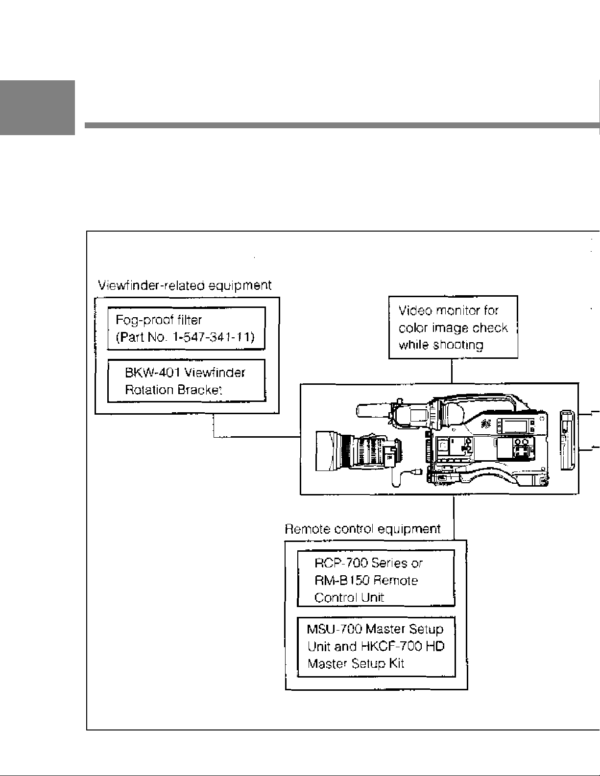
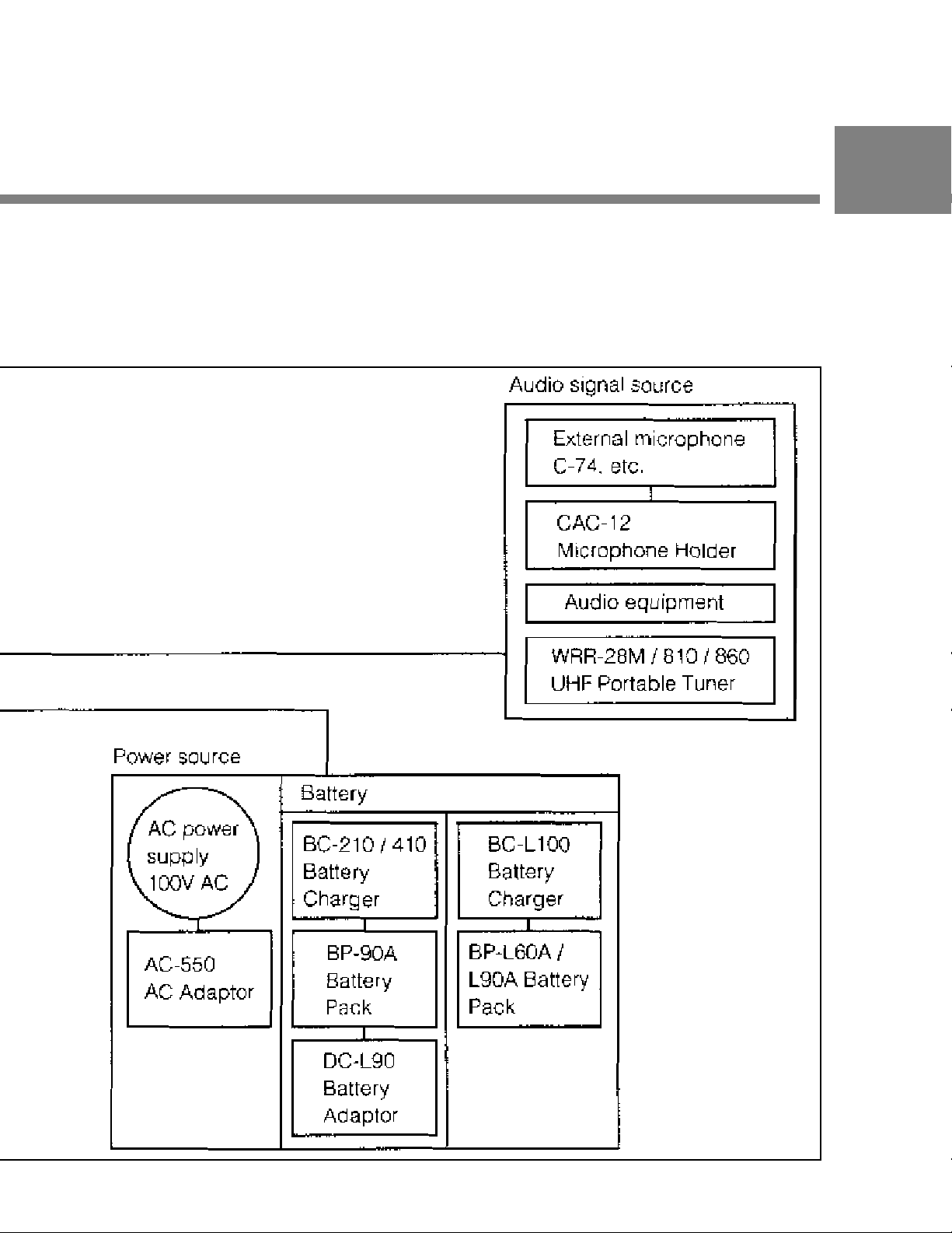
1-2 Example of System
Configuration
The diagram below shows a typical configuration of the camcorder for
ENG and EFP .
For more information about the fittings, connections, or use of additional
equipment and accessories, see Chapter 5 as well as the operation manuals for the
connected equipment.
1- 4 Chapter 1 Overview
Page 13
1
Chapter 1 Overview 1-5
Page 14

1-3 Precautions
1
Use and Storage
Do not subject the camcorder to severe shocks
The internal mechanism may be damaged or the body warped.
After use
Always turn off the power .
Before storing the camcorder for a long period
Remove the battery pack.
Use and storage locations
Store in a level, ventilated place. A void using or storing the camcorder
in the following places.
• Places subject to temperature extremes
• V ery damp places
• Places subject to severe vibration
• Near strong magnetic fields
• In direct sunlight or close to heaters for extended periods
1-6 Chapter 1 Overview
Page 15
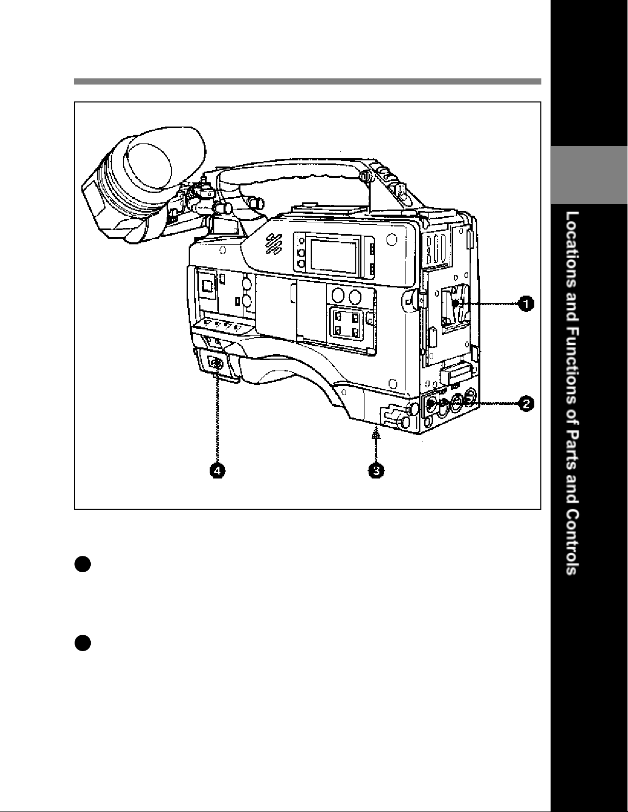
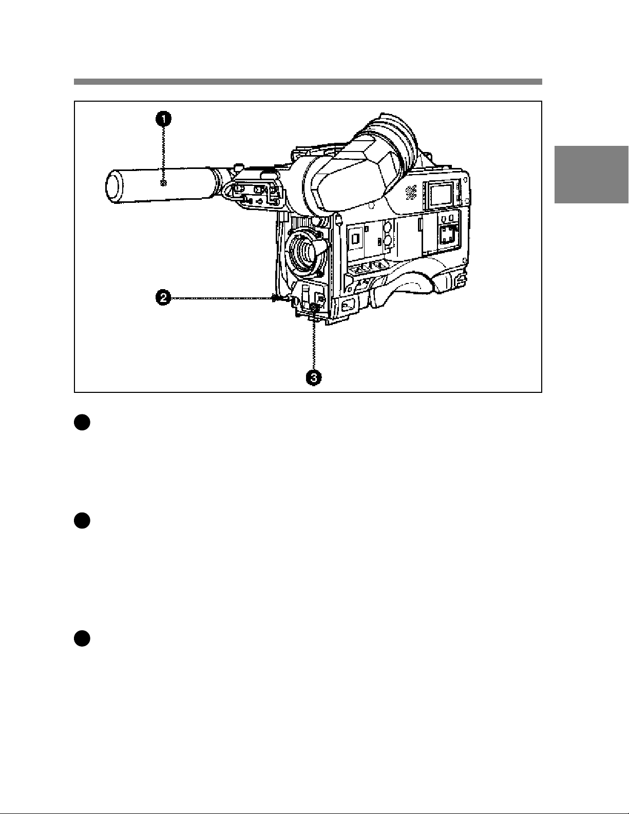
2-1 Power Supply
2
Power Supply
1
Battery attachment
Attach a BP-L60A/L90A battery pack. A DC-L90 Battery Adaptor for
loading a BP-90A Battery Pack also can be attached.
2
DC IN (external power input) connector (XLR type, 4-pin, male)
T o operate the HDW -700A using an AC power supply , connect an AC550 AC Adaptor with the DC output cable supplied with the adaptor .
T o use an external battery , connect its DC output cable to the DC IN
connector.
Chapter 2 Location and Functions of Parts and Controls 2-1
Page 16

2
3
BREAKER button
If excessive current flows within the unit, the breaker is tripped
automatically to shut off the power supply and protect the equipment.
After performing internal checks or adjustments, use a pointed object
such as a pen to press down lightly on this button. If there is no problem,
the power will again be supplied.
4
. POWER switch
This switch turns the main power supply on and off.
2-2 Chapter 2 Locations and Functions of Parts and Controls
Page 17
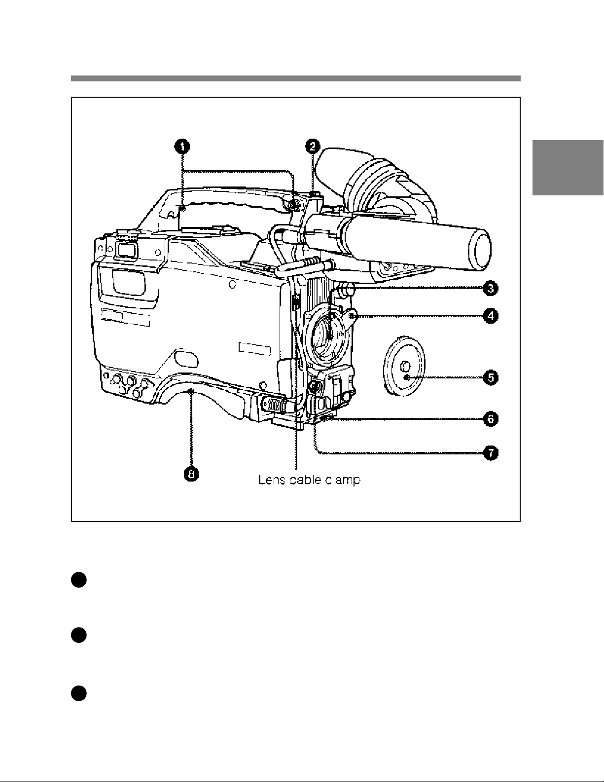
2-2 Accessory Attachments
2
Accessory attachments
1
Shoulder strap posts
Attach the supplied shoulder strap to these posts.
2
Light Shoe
Attach an optional accessory such as a video light to this shoe.
3
Lens mount (special bayonet mount)
Use this for mounting the lens.
Chapter 2 Locations and Functions of Parts and Controls 2-3
Page 18

4
Lens locking lever
After inserting the lens in the lens mount, rotate the lens mount ring with
this lever to lock the lens in position.
2
5
Lens mount cap
Remove this cap by pushing up on the lens locking lever . For protection
from dust, always insert this cap when no lens is mounted.
6
T ripod mount
When using the unit on a tripod, attach the supplied tripod adaptor .
7
LENS connector (12-pin)
Fit the lens cable to this connector . Contact your Sony representative for
more information about the lens you are using.
8
Shoulder pad
Y ou can move the shoulder pad forwards or backwards by loosening the
two screws. Do this to ensure the best balance when shooting with the
camcorder on your shoulder .
2-4 Chapter 2 Location and Functions of Parts and Controls
Page 19
2-3 Audio Functions
2
Audio functions (1)
1
Microphone
This is a super-cardioid directional microphone with an external power
supply (+48 V) system. Y ou can use it as an interview microphone by
connecting it to an extension cable (not supplied).
2
MIC IN (microphone input) connector (XLR type, 3-pin, female)
The supplied microphone connects to this connector . You can connect a
microphone other than the supplied one as long as it corresponds to an
external power supply system. The connector supplies power (+48 V) to
the microphone.
3
MIC/MENU knob
This knob adjusts the audio level of the front microphone. T o adjust the
front microphone level, set the VF DISP switch to ON, then push the
MENU switch to CANCEL. The audio level indication will appear on
the viewfinder screen. Note that you can do this only when the AUDIO
SELECT CH-1 / CH-2 switches are set to MANUAL and the AUDIO IN
switches are set to FRONT .
Chapter 2 Locations and Functions of Parts and Controls 2-5
Page 20
2
Audio functions (2)
2-6 Chapter 2 Locations and Functions of Parts and Controls
Page 21

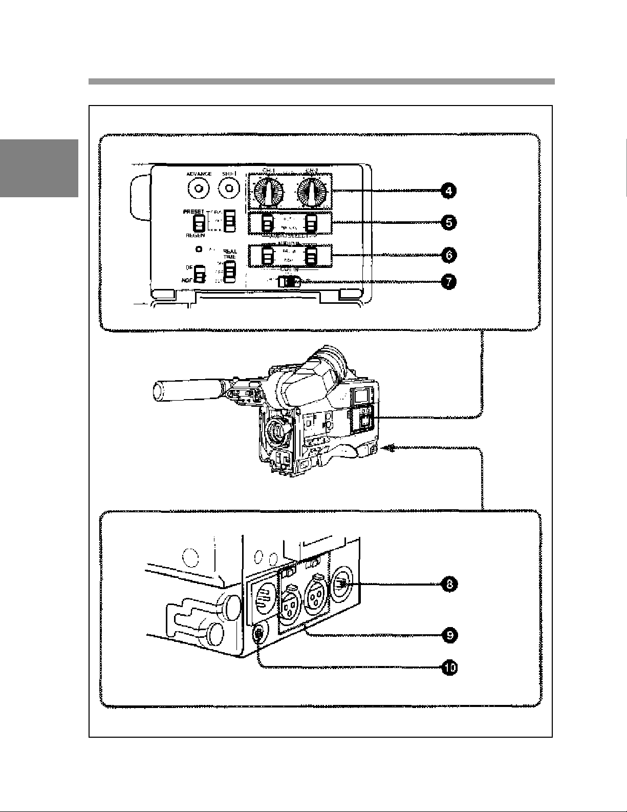
4
AUDIO LEVEL CH-1 / CH-2 (audio channel 1 and channel 2
recording level) controls
These controls adjust the audio levels of channels 1 and 2 when audio
input is from the AUDIO IN CH-1 / CH-2 connectors and the AUDIO
SELECT CH-1 / CH-2 switches are set to MANUAL.
5
AUDIO SELECT CH-1 / CH-2 (audio channel –1 and channel – 2
adjustment method select) switches
These switches select the audio level adjustment method for each of
audio channels 1 and 2.
AUTO: Use automatic adjustment.
MANUAL: Adjust the audio level manually.
6
AUDIO IN (audio input) switches
These switches select the audio input signals to be recorded for audio
channels 1 and 2.
FRONT: The input signal source is the microphone connected to the
MIC IN connector .
REAR: The input signal source is the audio equipment connected to the
2
AUDIO IN CH-1 / CH-2 connectors.
7
CUE IN (cue track input) switch
This switch selects the input signal to be recorded on the cue track.
CH-1: CH-1 input signal
MIX: Mixed input signals of CH-1 and CH-2
CH-2: CH-2 input signal
8
AUDIO OUT (audio output) connector (XLR type, 3-pin, male)
The connector outputs the audio signal selected by the MONITOR
switch.
Chapter 2 Locations and Functions of Parts and Controls 2-7
Page 22

9
AUDIO IN CH-1 / CH-2 (audio channel 1 and channel 2 input)
connectors (XLR type, 3-pin, female) and LINE/MIC/+48 V ON
(line input/microphone input/external power supply +48 V on)
2
switches
These are audio input connectors for channels 1 and 2 to which you can
connect audio equipment or a microphone.
The LINE / MIC / +48V ON switches select the audio source of the audio
input signals connected to each of these connectors.
LINE: Line input audio equipment
MIC: Microphone with an internal power supply
+48 V ON: Microphone with an external power supply system
10
DC OUT (DC power output) connector
This connector supplies power for a WRR-28M / 860 UHF Portable T uner
(not supplied). Do not connect any equipment other than the UHF
portable tuner .
2-8 Chapter 2 Locations and Functions of Parts and Controls
Page 23
Audio functions (3)
2
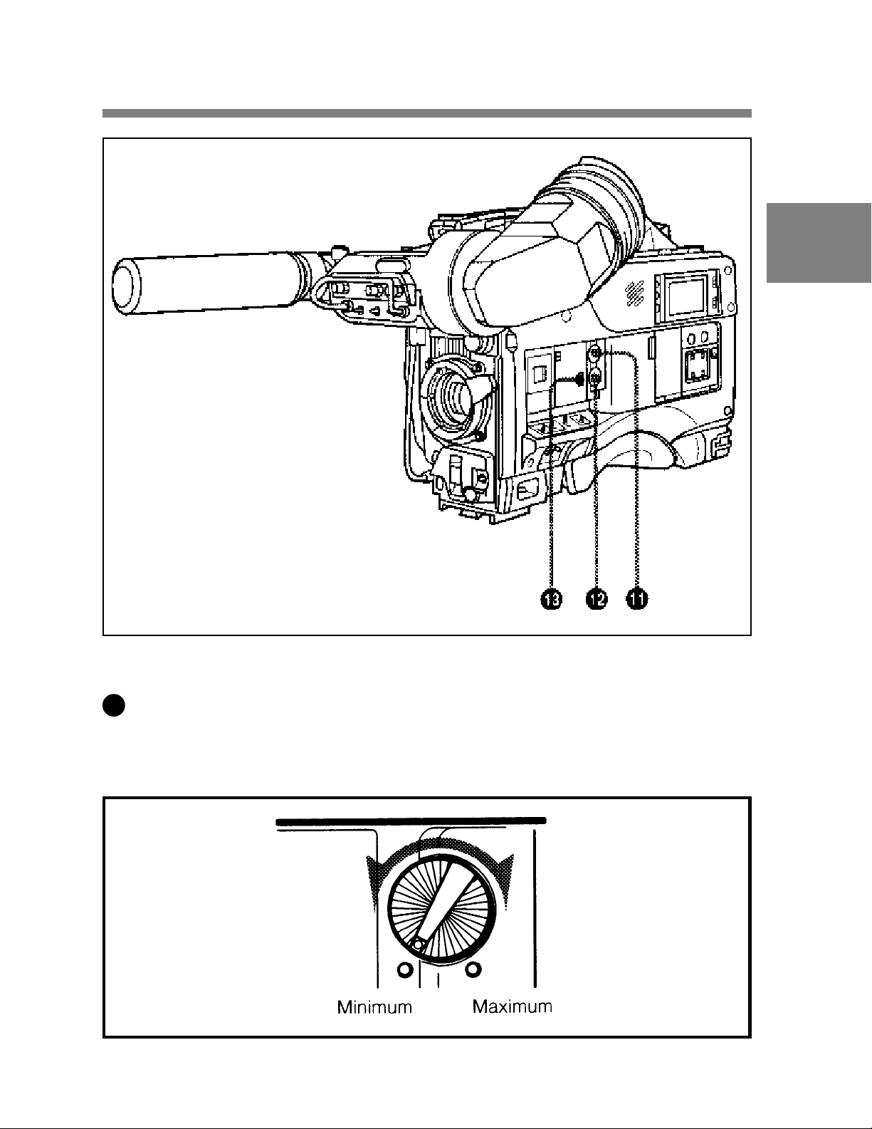
11
4 ALARM volume control
This control adjusts the speaker or earphone alarm volume. At the
minimum position, no sound can be heard.
ALARM volume control
Chapter 2 Locations and Functions of Parts and Controls 2-9
Page 24
2
The internal volume control can be adjusted so that the alarm is audible
even if the ALARM volume control is at the minimum position.
For more information, refer to the Maintenance Manual.
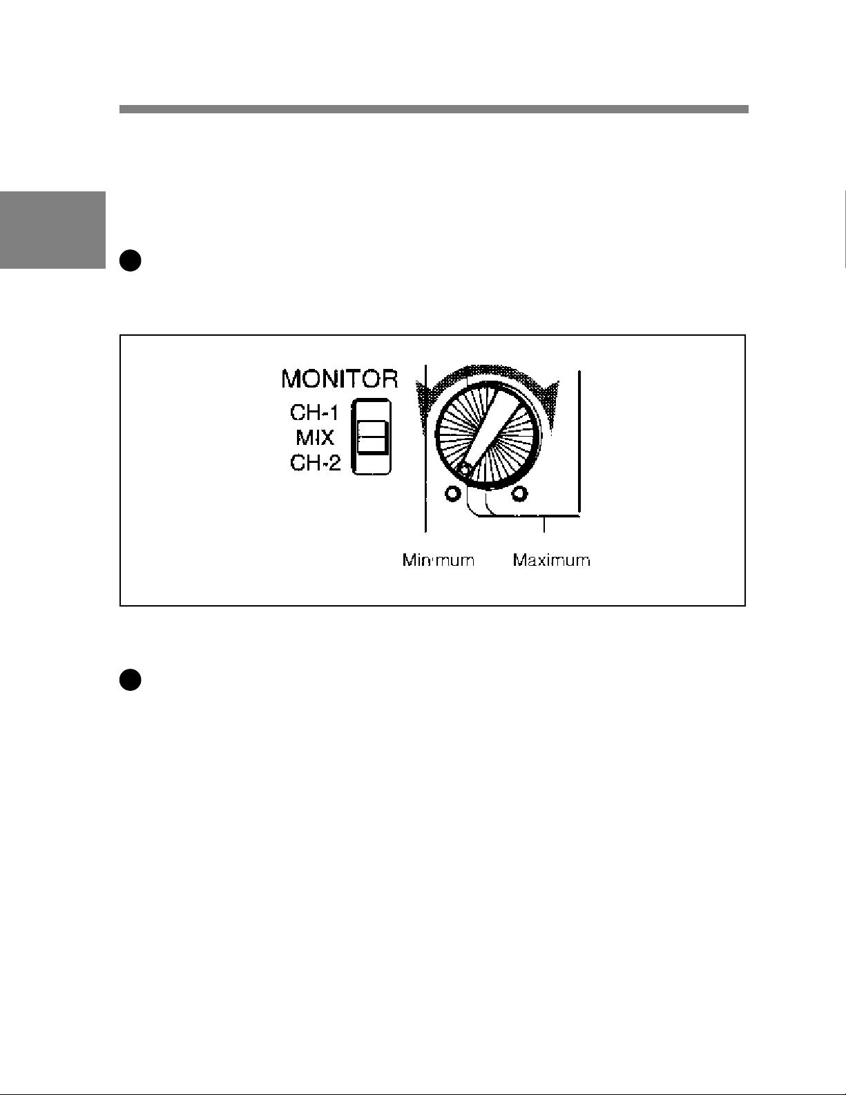
12
4 MONITOR volume control
This control adjusts the speaker or earphone volume for sounds other
than the alarm sound. At the minimum position, no sound can be heard.
MONITOR volume control
13
5 MONITOR (audio channel select) switch
This switch selects the audio channel to be output from the speaker or
earphone.
CH-1: Channel 1 audio
MIX: Mixed sound of channels 1 and 2
CH-2: Channel 2 audio
2-10 Chapter 2 Locations and Functions of Parts and Controls
Page 25
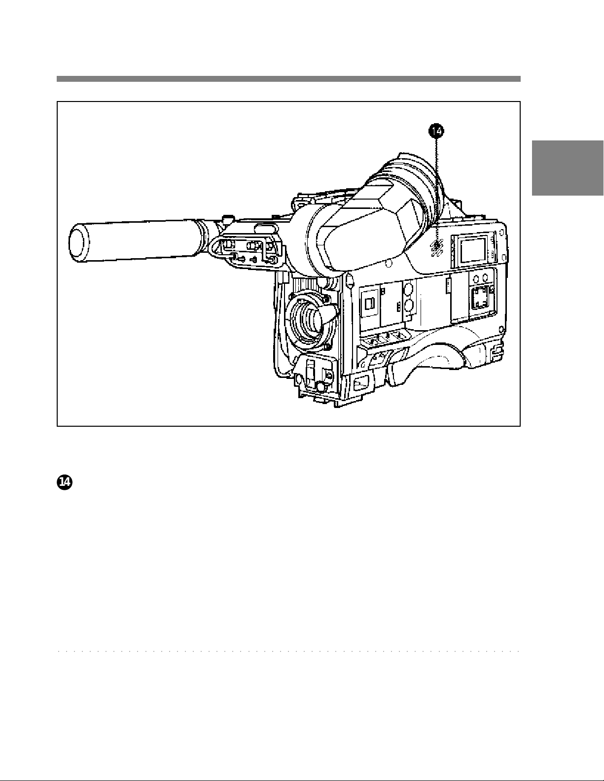
Audio functions (4)
2
14
4 Built-in speaker
During recording, the speaker can be used for monitoring the E-E
1)
sound, and during playback for monitoring playback sound. The speaker
also sounds alarms to reinforce visual warnings.
If an earphone is plugged into the EARPHONE jack, the speaker
sound is automatically cut off.
See Section 6-3 “Operation Warnings” (page 6-12) for information about alarms.
○○○○○○○○○○○○○○○○○○○○○○○○○○○○○○○○○○○○○○○○○○○○○○○○○○○○○○○○○○○
1) E-E sound (Electric-to-Electric sound)
The term E-E sound refers to an audio signal that has passed through the
amplifier, but has not been recorded on the tape. In other words, you can directly
monitor the recording input signal, as opposed to the simultaneous playback
(output) signal.
Chapter 2 Locations and Functions of Parts and Controls 2-1 1
Page 26
2
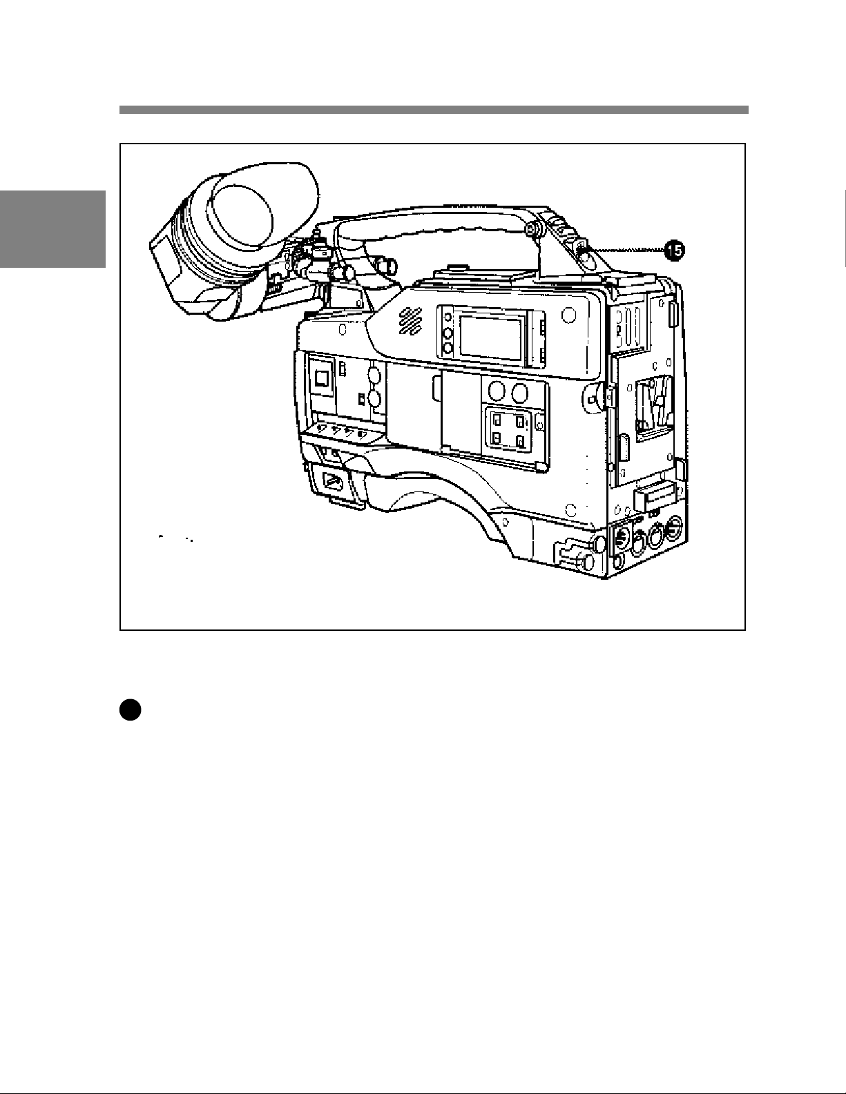
Audio functions (5)
15
4 EARPHONE jack
Y ou can monitor the E-E sound during recording and playback sound
during playback. Plugging an earphone into the jack automatically cuts
off the built-in speaker , and you hear the alarms about the camcorder’ s
operation and status through the earphone.
2-12 Chapter 2 Locations and Functions of Parts and Controls
Page 27
2-4 Shooting and Recording/
Playback Functions
2
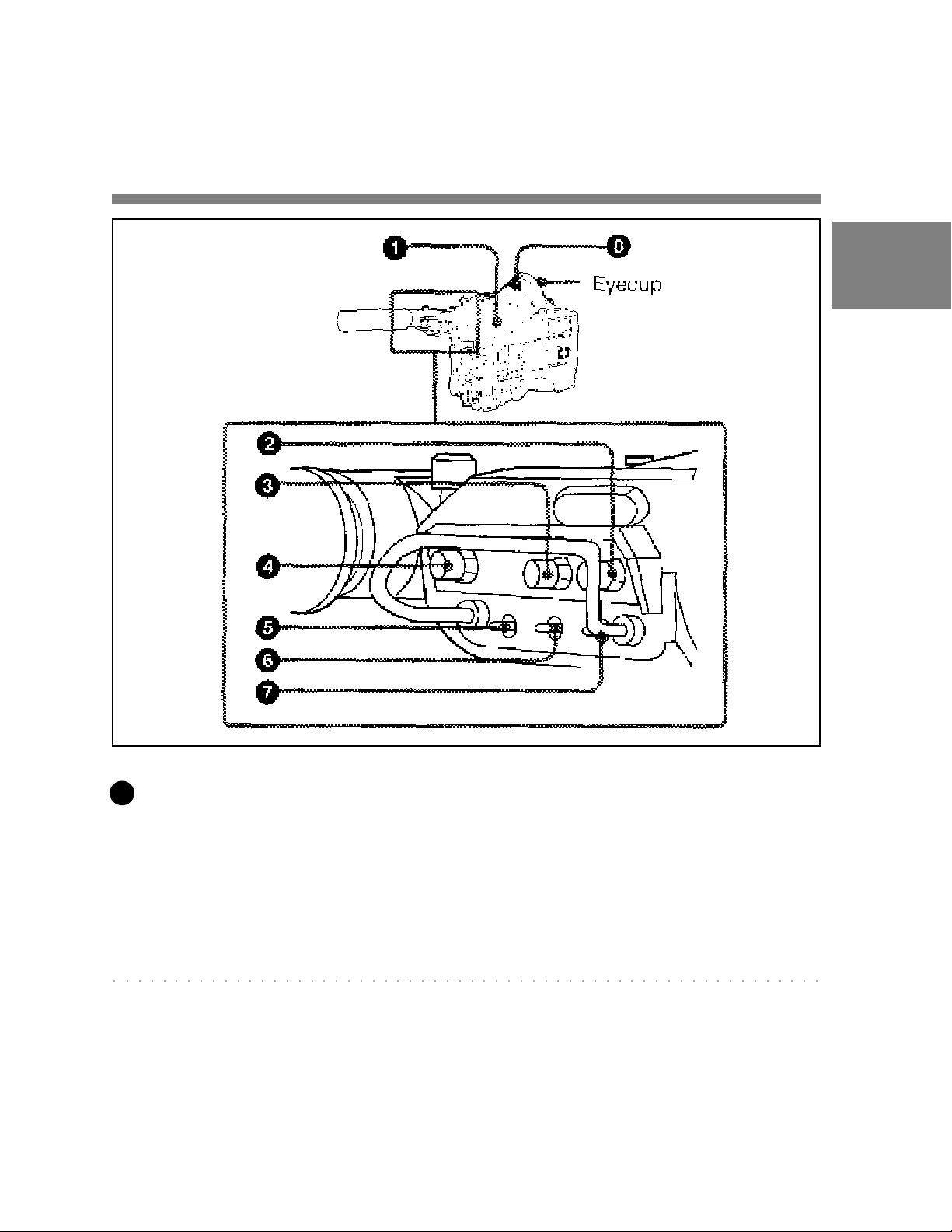
Shooting and recording/playback functions (1)
1
V iewfinder
The viewfinder lets you view the camera image in black and white
while shooting the picture and also see the playback picture from the
VTR. It also displays various warnings and messages related to the
settings or operating conditions of the camcorder , a zebra pattern1), safety
zone marker2), and center marker3).
○○○○○○○○○○○○○○○○○○○○○○○○○○○○○○○○○○○○○○○○○○○○○○○○○○○○○○○○○○
1) Zebra pattern
The zebra pattern aids in manual iris adjustment by indicating areas of the
picture where the video level is approximately 70% and 100% and above.
2) Safety zone marker
The safety zone marker is a rectangle indicating the effective picture area.
For more information, see Section 4-7-3 “Setting the Marker Display” (page 4-42)
3) Center marker
The center marker indicates the center of the picture with a crosshair .
Chapter 2 Locations and Functions of Parts and Controls 2-13
Page 28

2
BRIGHT (brightness) control
This control adjusts the picture brightness on the viewfinder screen. It
has no effect on the camera output signal.
2
3
CONTRAST control
This control adjusts the picture contrast on the viewfinder screen. It has
no effect on the camera output signal.
4
PEAKING control
This control adjusts the sharpness of the picture on the viewfinder screen
to make focusing easier . It has no effect on the camera output signal.
5
DISPLA Y / ASPECT (display/aspect control) switch
Use this switch to turn the markers on or off and to change the VF scan
mode.
DISPLAY: When MARKER in the OPERATION menu is set to ON,
pushing this switch to DISPLA Y toggles the markers on the
viewfinder screen on and off.
ASPECT: Pushing this switch to ASPECT toggles the viewfinder
screens aspect ratio between 16:9 and 4:3.
2-14 Chapter 2 Locations and Functions of Parts and Controls
Page 29

6
ZEBRA (zebra pattern) switch
This switch controls the zebra pattern on the viewfinder screen.
ON: The zebra pattern is displayed and stays.
OFF: No zebra pattern is displayed.
MOMENT: The zebra pattern is displayed and stays for 5 to 6 seconds.
The zebra pattern is factory set to indicate picture areas where the
video level is approximately 70%. The setup menu can be used to
specify that areas where the video level is 100% and above are to be
displayed at the same time.
For information about how the zebra pattern is to be displayed to
indicate areas of 100% or more, see Section 4-7-6 “Setting the Viewfinder”
(page 4-47).
7
T ALL Y switch
2
This switch controls the TALL Y indicator ( on page 2-36), setting its
1
brightness (HIGH or LOW) or turning it off.
HIGH: The T ALL Y indicator gets brighter.
OFF: The TALL Y indicator does not operate.
LOW : The T ALL Y indicator gets dimmer .
8
Diopter adjustment ring
Use this ring to adjust the viewfinder image for your vision.
Chapter 2 Locations and Functions of Parts and Controls 2-15
Page 30
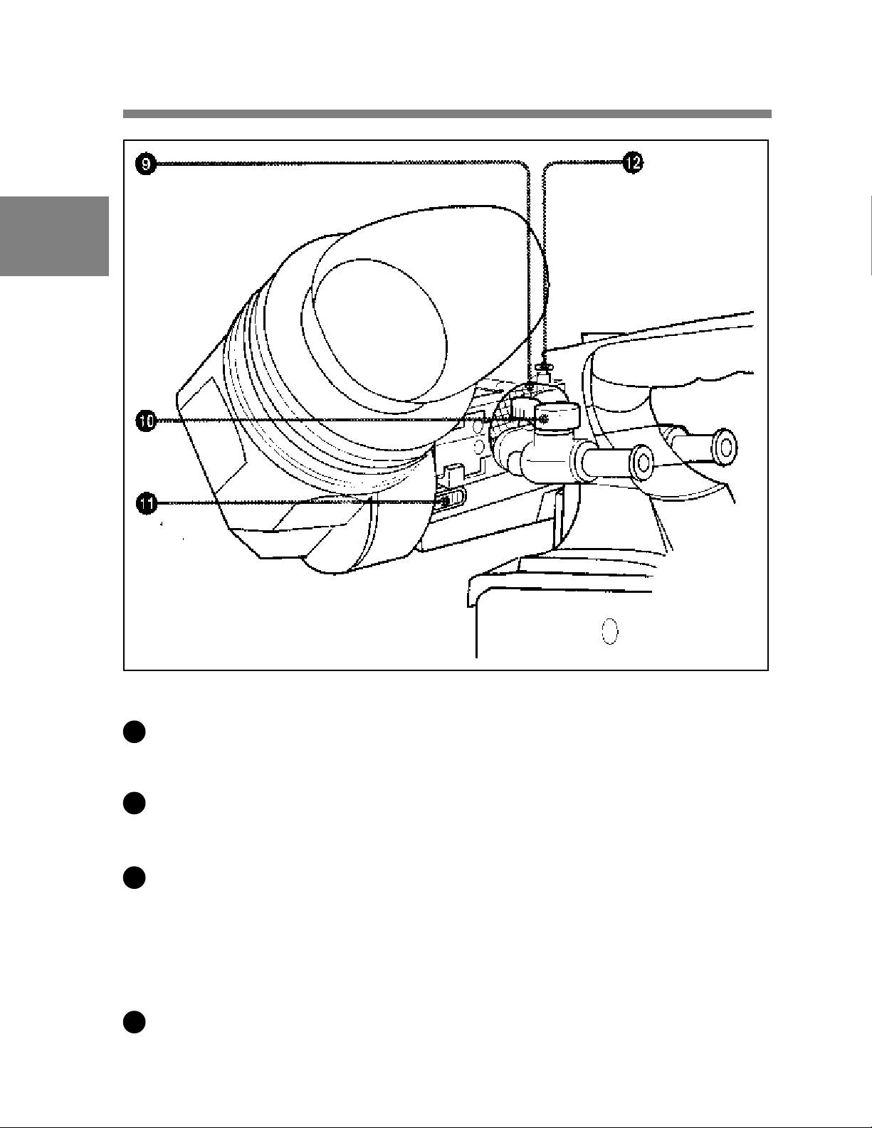
2
Shooting and recording/playback functions (2)
9
Viewfinder left-right positioning ring
Use this ring to move the viewfinder sideways.
10
Viewfinder front-rear positioning lever
Use this lever to move the viewfinder forward or backward.
11
Cameraman tally indicator
This indicator lights while the camcorder is operating.
Slide the window open when you shoot, keeping your eye away from the
viewfinder . This indicator flashes when the battery level is running low
or the tape is nearing its end.
12
Viewfinder stopper
Pull up this stopper to detach the viewfinder from the camera.
2-16 Chapter 2 Locations and Functions of Parts and Controls
Page 31

2
Shooting and recording/playback functions (3)
13
FIL TER selector
This selector is a dual knob that selects the most appropriate filter to
match the light source illuminating the subject. The outer knob selects
the color temperature of the CC (Color Conversion) filter, and the inner
knob selects the type of ND (Neutral Density) filter . When this selector
is adjusted, the new setting will be indicated on the viewfinder screen for
about 3 seconds. The white balance is stored in memory for each CC
filter.
Chapter 2 Locations and Functions of Parts and Controls 2-17
Page 32

The relationships between the selector settings and filter selections as
well as examples of filters for different shooting conditions are given
below.
2
FILTER selector (outer) setting and CC filter selection
FIL TER selector (outer) setting CC filter selection
A Cross filter
B 3200K
C 4300K
D 6300K
a)
a) A type of special effect filter. Generates a cross-hair light ray on a highlighted
portion.
FILTER selector (inner) setting and ND filter selection
FIL TER selector (inner) setting ND filter selection
1 Clear
2 1/4 ND
3 1/16 ND
4 1/64 ND
Examples of shooting conditions and appropriate filters
Shooting condition CC filter ND filter
Sunrise and sunset; B(3200 K) 1 (clear)
inside studio
Clear skies C (4300 K) or 2 (1/4 ND) or
D (6300 K) 3(1/16 ND)
Cloudy or raining D (6300 K) 1 (clear) or
2 (1/4 ND)
Very bright conditions C (4300 K) or 3 (1/16 ND) or
such as snow , at high D (6300 K) 4 (1/64 ND)
altitudes, or at the seashore
2-18 Chapter 2 Locations and Functions of Parts and Controls
Page 33

14
SHUTTER selector
Set this selector to ON to use the electronic shutter . Set it to SEL to
switch the shutter speed or mode setting within the range that has been
previously set from the setup menu.
When this selector is adjusted, the new setting will be indicated on the
setting change / adjustment progress message display area for about 3
seconds.
For more information about the shutter speed and mode settings, see Section 4-2
“Setting the Electronic Shutter” (page 4-9).
15
MIC/MENU knob
When the DISP switch is set to ON or when the lens is using the
automatic iris operation with the DISP switch set to OFF, pressing and
turning the MIC/MENU knob sets the iris override (+ 1 iris in 1/4 iris
steps). The iris override setting returns to 0 when you turn off the
camcorder, then on again.
2
16
AUTO W/B BAL (automatic white / black balance adjustment)
switch
This switch activates the white balance and black balance automatic
adjustment functions.
WHT: Automatic adjustment of the white balance. If the WHITE BAL
switch is set to A or B, the white balance setting is stored in the
corresponding memory . The memory can store the white balance
setting for each CC filter .
BLK: Automatic adjustment of the black set and black balance.
Chapter 2 Locations and Functions of Parts and Controls 2-19
Page 34

17
GAIN selector
This selector switches the gain of the video amplifier to match the
lighting conditions during shooting. The gains corresponding to the L,
2
M, and H, settings are selected from the setup menu before use. The
factory settings are L = 0 dB, M = 6 dB, and H = 12 dB.
When this selector is adjusted, the new setting will be indicated on the
setting change/ adjustment progress message display area of the
viewfinder screen for about 3 seconds.
For information about setting the gain values, see Section 4-7-5 “Setting the GAIN
Selector Values” (page 4-45).
18
OUTPUT / DCC (output signal / dynamic contrast control) selector
This selector switches the video signal that is output to the VTR,
viewfinder, and video monitor , between the color bar signal and the
camera output. It also switches DCC1) on and off when output from the
camera is selected.
○○○○○○○○○○○○○○○○○○○○○○○○○○○○○○○○○○○○○○○○○○○○○○○○○○○○○○○○○○
1) DCC (Dynamic Contrast Control)
Also called automatic knee. Against a very bright background with the iris
opening adjusted to the subject, objects in the background will be lost in the
glare. The DCC function will suppress the high intensity and restore much of
the lost detail and is particularly effective in the following cases.
• Shooting a subject against a bright sky
• Shooting a subject indoors, against a background through a window
• Any high contrast scenes
2-20 Chapter 2 Locations and Functions of Parts and Controls
Page 35

OUTPUT/DCC selector
19
WHITE BAL (white balance memory) switch
This switch determines the source of the white balance settings.
PRST (preset): Adjusts the color temperature corresponding to the
2
position of the FIL TER selector (outer knob). Use the PRST setting
when you have no time to adjust the white balance.
A or B: When the AUTO W / B BAL switch is pushed to WHT , the
white balance is automatically adjusted according to the current
position of the FIL TER selector (outer knob), and the adjusted value
is stored in either memory A or memory B. (There are two memories
for each CC filter, so a total of eight adjustments can be stored).
When the FIL TER selector (outer knob) is at the same position as it
was when this WHITE BAL switch was adjusted, the stored value is
called from memory , and the camcorder automatically adjusts itself
to that value.
When this switch is adjusted, the new setting will be indicated on the
setting change / adjustment progress message display area of the
viewfinder screen for about 3 seconds.
Chapter 2 Locations and Functions of Parts and Controls 2-21
Page 36

2
Shooting and recording/playback functions (4)
20
GENLOCK IN (genlock input) connector (BNC type)
This connector inputs an HD reference signal when the camera is to be
genlocked or when the time code is to be synchronized with external
equipment. Use the MAINTENANCE menu to adjust the genlock Hphase (phase of Horizontal sync signal).
For details, refer to the Maintenance Manual.
21
REMOTE (remote control) connector (8-pin)
Connect the RCP-700 Series or RM-B150 Remote Control Unit (not
supplied) with which VTR control is possible. Y ou can also connect and
use the MSU-700 Master Setup Unit (not supplied).
2-22 Chapter 2 Locations and Functions of Parts and Controls
Page 37

Shooting and recording/playback functions (5)
2
22
MONITOR OUT connector (BNC type)
This connector outputs the HD video signal (75-ohm terminated, Y / PB /
PR). T o include the text on the viewfinder screen with the output signal,
push the VF DISP switch to MENU while pushing the MENU switch to
CANCEL. T ext output is cancelled when you turn the camcorder off,
then on again.
Chapter 2 Locations and Functions of Parts and Controls 2-23
Page 38

2
Shooting and recording/playback functions (6)
2-24 Chapter 2 Locations and Functions of Parts and Controls
Page 39

23
VTR ST ART button
Press this button to start recording. Press it again to stop recording. The
effect is exactly the same as that of the VTR button on the lens.
24
VTR SAVE / STBY (VTR power saving / standby) switch
This switch controls the VTR power mode during pauses in recording
(REC P AUSE).
SAVE: Power saving mode. When you press the VTR ST AR T button,
there is a short delay before recording starts, but power consumption
is less than in standby mode, and battery life is extended. When the
switch is set to SAVE, the VTR SAVE indicator in the viewfinder
lights.
STBY: S tandby mode. Recording starts as soon as you press the VTR
ST AR T button.
25
EJECT (cassette eject) button
Press this button to eject or load a cassette.
26
REW (rewind) button and indicator
2
Press this button to rewind the tape. The indicator lights during
rewinding.
27
FWD (fast forward) button and indicator
Press this button to fast forward the tape. The indicator lights during fast
forward.
Chapter 2 Locations and Functions of Parts and Controls 2-25
Page 40

26
PLA Y (playback) button and indicator
Press this button to view the recorded picture in the viewfinder or on the
color video monitor . The indicator lights during playback.
2
The 3 times normal speed search function is provided to make it far
quicker to find a desired location of the tape. Press the REW button or F
FWD button during playback to view the 3 times normal speed search
picture.
27
STOP button
Press this button to stop the tape.
2-26 Chapter 2 Locations and Functions of Parts and Controls
Page 41

2-5 Setup Menu Operating
Section
2
Setup menu operating section
1
Setup card compartment
Lift the OPEN lever to open the cover and insert the supplied Setup Card
into the slot with the “SONY” logo facing you (a Setup Card was already
inserted at the factory).
2
MIC/MENU knob
Use this knob to change the page selection or a setting within the setup
menu.
Chapter 2 Locations and Functions of Parts and Controls 2-27
Page 42

2
3
MENU switch
Push this switch to CANCEL to erase the menu settings and return to
page selection mode or the TOP menu. Push the switch up to display the
‘!’ LED page of the operation menu.
For details on settings of this page, see Section 4-7-2 “Selecting the Items for
Which the ‘!’ LED is to light” (page 4-40).
4
VF DISP switch
Use this switch to change the display on the viewfinder screen.
ON: A message or character indicating the camcorder’s settings or
operation status is displayed on the viewfinder screen.
OFF: The display on the viewfinder screen disappears.
MENU: The setup menu is displayed on the viewfinder screen.
2-28 Chapter 2 Locations and Functions of Parts and Controls
Page 43

2-6 Time Code System
2
Time code functions (1)
1
GENLOCK IN (genlock input) connector (BNC type)
This connector inputs an HD reference signal when the camera is to be
genlocked or when the time code is to be synchronized with external
equipment.
Chapter 2 Locations and Functions of Parts and Controls 2-29
Page 44

2
Time code functions (2)
3
TC IN (time code output) connector (BNC type)
T o synchronize the time code with an external time code, connect the
reference time code input here.
3
TC OUT (time code output) connector (BNC type)
T o synchronize the time code of an external VTR with that of the
camcorder, connect this connector to the time code input lock connector
of the external VTR.
2-30 Chapter 2 Locations and Functions of Parts and Controls
Page 45

2
Time code functions (3)
Chapter 2 Locations and Functions of Parts and Controls 2-31
Page 46

2
4
HOLD (display hold) button
Pressing this button instantly freezes the time data displayed in the
counter display section. (The time code generator continues normal
operation.) Pressing this button again releases the hold. One use of this
feature is to determine the exact time of a particular shot.
See Section 2-8 “Warnings and Indications on the Display Panel” (page 2-38) for
more information about the counter display.
5
RESET (counter reset) button
This button resets the time data displayed on the counter display section
to “00:00:00:00” and the user bit data to “000000000”.
6
DISPLA Y switch
Depending on the settings of the F-RUN / SET/ R-RUN switch and the
REAL TIME switch, this switch selects data to display in the counter
display section as follows:
CTL: Control signal
U-BIT: User bits
TC: Time Code
For more information see “Time code displays” (page 2-40).
7
ADVANCE button
For setting the time code, user bits, or real time, each press of this button
increments the flashing digit selected by the SHIFT button.
8
SHIFT button
For setting the time code, user bits, or real time, this button selects the
digit to be changed. The selected digit flashes.
2-32 Chapter 2 Locations and Functions of Parts and Controls
Page 47

9
PRESET / REGEN (preset / regeneration) switch
This switch selects whether to set a new time code or to match the
existing time code that had been recorded.
PRESET: S tarts recording time code values on the tape from the newly
set value.
REGEN: Reads the existing time code on the tape and sets the time code
starting value accordingly . Thus, even when there is an indefinite
break in recording, this setting ensures that time codes on the tape
will be continuous. Regardless of the setting of the F-RUN/SET/R-
RUN switch, the camcorder operates in R-RUN mode.
10
F-RUN/SET/R-RUN (free run/set/recording run) switch
This switch selects the operating mode for the internal time code
generator .
F-RUN: The time code generator keeps running, regardless of the
operation state of the VTR. Use this position when matching the
2
time code to real time or for synchronizing the time code with an
external time code.
SET: Set the switch to this position to set the time code or user bits.
R-RUN: The time code generator runs only while recording. This
produces a tape with consecutive time code value, even when shot
intermittently.
For more information, see Section 4-4-1 “Setting the User Bits” (page 4-17) and
Section 4-4-2 “Setting the Time Code” (page 4-19).
Chapter 2 Locations and Functions of Parts and Controls 2-33
Page 48

2
11
DF / NDF (drop frame / non-drop frame) switch
This switch selects whether the time code advances in drop frame mode
or non-drop frame mode.
DF: Drop frame mode
NDF: Non-drop frame mode
12
REAL TIME switch
1)
2)
The switch selects whether or not real time is to be recorded as VITC
user bit data. It is also used for setting the real time.
ON: Real time is recorded as VITC user bit data.
OFF: Real time is not recorded as VITC user bit data.
SET: Sets the real time.
○○○○○○○○○○○○○○○○○○○○○○○○○○○○○○○○○○○○○○○○○○○○○○○○○○○○○○○○○
1) Drop frame mode
T o eliminate the discrepancy between the actual time and the time code value
generated by the time code generator when the field frequency is 59.94 Hz, drop
frame mode drops two frames (frame 00 and 01) from the time code value at
the beginning of each minute except every tenth minute.
2) Non-drop frame mode
Non-drop frame mode does not perform the processing of drop frame mode. As
a result, when the field frequency is 59.94 Hz, there will be a discrepancy
between the actual time and the time code value of about 86 seconds per one day
of recording.
2-34 Chapter 2 Locations and Functions of Parts and Controls
Page 49

2-7 Warnings and Indications
The camcorder supplies you visual information and warnings by means
of its indicators without you having to use the speaker , earphone or
viewfinder .
2
Warning and indication functions
Chapter 2 Locations and Functions of Parts and Controls 2-35
Page 50

2
1
T ALL Y indicator
Setting the T ALLY switch to HIGH or LOW activates this indicator .
The indicator lights during recording on the VTR. It also provides the
same information as the REC indicator in the viewfinder; it lights up
during recording and flashes to indicate a problem. The brightness of
this indicator when it is lit can be controlled by the T ALLY switch.
2
T ALL Y switch
This switch controls the T ALLY indicator , setting its brightness (HIGH
or LOW) or turning it off.
HIGH: The T ALL Y indicator gets brighter.
OFF: The T ALLY indicator does not operate.
LOW : The T ALL Y indicator gets dimmer .
3
DIAG (self-diagnostics) button
Pressing this button when the VTR is stopped switches the camcorder to
self-diagnostics mode. In self-diagnostics mode, it is possible to carry
out a display panel test, a VTR test, or a camera test and display the test
result.
T o exit from self-diagnostics mode, press this button once more.
Refer to the Maintenance Manual for more information.
4
BACK T ALL Y indicator
This indicator functions exactly the same way as the front tally indicator
when the BACK T ALLY switch is set to ON.
5
BACK T ALL Y switch
This switch enables (ON) or disables (OFF) the operation of the BACK
T ALL Y indicator.
ON: Enables the BACK T ALLY indicator operation.
OFF: Disables the BACK T ALLY indicator operation.
2-36 Chapter 2 Locations and Functions of Parts and Controls
Page 51

6
W ARNING indicator
This indicator lights up or flashes when there is a fault in the VTR.
See Section 6-3 “Operation Warnings” (page 6-12) for more information about the
relationships between the operation of the indicator and the meanings of the
indications.
7
LIGHT switch
This switch controls the display panel light.
ON: Turns the panel light on.
OFF: Turns the panel light of f.
8
Display panel
VTR error messages, battery status, tape status, audio level, time data,
and so forth are displayed on this panel.
For more information, see Section 2-8 “Warnings and Indications on the Display
Panel” (page 2-38).
2
Chapter 2 Locations and Functions of Parts and Controls 2-37
Page 52

2
2-8 Warnings and Indications
on the Display Panel
T ape st atus, battery st atus, and level indicators
Tape status, battery status, and level indicators
2-38 Chapter 2 Locations and Functions of Parts and Controls
Page 53

VTR operation status and status indicators
2
VTR operation and status indicators
Note
If the tape in the VTR becomes slackened, an error code appears
automatically on the display section of the display panel.
For more information refer to the Maintenance Manual.
Chapter 2 Locations and Functions of Parts and Controls 2-39
Page 54

2
Time code displays
Time code displays
2-40 Chapter 2 Locations and Functions of Parts and Controls
Page 55

Relationships between the REAL TIME, F-RUN/SET/R-RUN,
and DISPLAY switch settings and the time counter displays
The time counter display is determined first by the REAL TIME switch
setting, then by the F-RUN / SET / R-RUN switch setting, and finally by
the DISPLA Y switch setting.
Switch settings related to time code and displayed information
REAL TIME F-RUN/SET/R-RUN DISPLAY Displayed
switch position switch position switch position information
ON or OFF SET TC or CTL Time code
U-BIT User bits
F-RUN or CTL CTL
R-RUN T C Time code
U-BIT User bits
2
SET Any position Any position Real time
Chapter 2 Locations and Functions of Parts and Controls 2-41
Page 56

Page 57

3-1 About Cassettes
This section describes the procedure for loading and unloading a
cassette.
See “Specifications VTR Section” (page A-3) for information about the cassettes
you can use in the camcorder.
3-1-1 Loading and Unloading a Cassette
Loading a Cassette
1 Turn on the POWER switch.
3
2 Press the EJECT button.
The cassette lid will open
(Continued)
Chapter 3 Recording and Playback 3-1
Page 58

3
3 Check that there is no slack in the tape. Then slide in the cassette
until it clicks into position and close the cassette lid completely by
pressing near the engraved “PUSH”.
Note
T o insert the tape correctly , make sure the tape in the cassette is facing
up towards you before you try to close the cassette lid.
Checking the tape for slack
Pressing in the reels lightly , turn them gently with your finger in the
directions shown below . If the reels will not move, there is no slack.
Checking the tape for slack
3-2 Chapter 3 Recording and Playback
Page 59

Unloading a cassette
With the power supply on, press the EJECT button to open the cassette
lid. Then take out the cassette. If you are not going to insert another
cassette, close the cassette lid.
It is possible to take out the cassette and close the cassette lid unless the
battery voltage drops below about 10.5 V. Do not repeat this unloading
operation.
Unloading a cassette manually
If the battery voltage drops below about 10.5 V, take out the cassette
manually as illustrated below .
3
Unloading a cassette manually
You need not return the screw to its original position after taking out the
cassette. Although the cassette lid is not locked, turning on the power
makes the cassette lid operable again.
Chapter 3 Recording and Playback 3-3
Page 60

3
3-1-2 Preventing Accidental Erasure
The following procedure prevents cassettes from being recorded
inadvertently.
Preventing accidental erasure
3-4 Chapter 3 Recording and Playback
Page 61

3-2 Recording
3-2-1 Basic Procedure
This section describes the basic procedure for shooting and recording.
Before a shooting session, ensure that the camcorder is functioning
properly.
For more information, see Section 6-1 “Testing the Camcorder Before Shooting”
(page 6-1).
T urning on the camcorder and loading a cassette
Follow the procedure below .
Basic procedure for shooting : from power supply to cassette loading
3
1 Attach a fully charged battery pack.
2 Set the Power switch to ON. Check that the HUMID indicator
does not appear and that the BATT indicator shows at least five
segments.
• If HUMID indicator appears, wait until it disappears
• If the BA T T indicator does not show at least five segments,
replace the battery pack with a fully charged one.
(Continued)
Chapter 3 Recording and Playback 3-5
Page 62

3
3 Check that there are no obstructions near the cassette lid. Then press
the EJECT button to open the cassette lid.
4 After checking the points below, load the cassette and close the
cassette lid.
• The cassette is not write-protected.
• There is no slack in the tape.
Basic procedure for shooting: from adjusting the
black balance and white balance to stopping recording
After turning on the power and loading a cassette, set the switches and
selectors as shown below and begin operation.
Switch and selector settingsbefore shooting
3-6 Chapter 3 Recording and Playback
Page 63

Shooting
Follow the procedure below .
3
Basic procedure for shooting: from adjusting the black balance and white
balance to stopping recording
1 Push the AUTO W / B BAL switch to BLK to adjust the black
balance.
2 Select the CC filter and ND filter to match the lighting conditions,
and adjust the white balance.
(Continued)
Chapter 3 Recording and Playback 3-7
Page 64

When the black balance and white balance settings are already
in memory:
Set the WHITE BAL switch to A or B.
When the white balance setting is not in memory and you do not
have enough time to adjust the white balance:
3
Set the WHITE BAL switch to the PRST position. The white
balance is automatically set to 3200 K when the FIL TER selector is
set to B, to 4300 K when the FILTER selector is set to C, and to
6300 K when the FIL TER selector is set to D.
For more information, see Section 4-1-3 “Adjusting the White Balance” (page
4-5).
3 Aim the camera at the subject and adjust the focus and zoom.
4 If necessary, set the electronic shutter for an appropriate mode and
speed.
For more information, see Section 4-2 “Setting the Electronic Shutter” (page
.
4-9)
5 To start recording, press the VTR ST AR T button or the VTR button
on the lens.
During recording, the REC indicator in the viewfinder goes on.
Perform zooming and focus control, if necessary .
6 To stop recording, press the VTR ST AR T button or the VTR button
on the lens again.
The REC indicator goes off.
3-8 Chapter 3 Recording and Playback
Page 65

Cassette control buttons
During recording, the cassette control buttons (EJECT , REW , FFWD,
PLA Y, STOP) have no effect.
3-2-2 Continuous Recording
If the camcorder is in the recording pause mode, simply pressing the
VTR ST AR T button on the camcorder or the VTR button on the lens
continues recording at exactly the next frame.
In other cases, you first need to position the tape at an appropriate point.
When the camcorder is in the recording pause mode
Pressing the VTR ST A RT button on the camcorder or the VTR button on
the lens positions the tape at the appropriate point automatically .
However , the time taken before recording starts depends on the setting of
the VTR SA VE/STBY switch.
• If the VTR SAVE/STBY switch is in the SAVE position, it takes about
4 seconds before recording starts.
• If the VTR SAVE/STBY switch is in the STBY position, recording
starts immediately . However, just after the switch position is changed
from SAVE to STBY, it takes about 4 seconds before recording starts.
3
Chapter 3 Recording and Playback 3-9
Page 66

3
If you turn off the power during a recording pause
Continuous recording after turning off the power during a recording pause
1 Turn on the power again.
2 Press the RET button on the lens.
The camcorder positions the tape at the appropriate point. Note,
however , that this function works only for continuously recorded
material or consecutively joined segments totaling at least 4 seconds
in length.
3 Press the VTR ST AR T button on the camcorder or the VTR button
on the lens start recording.
Continuous recording in other cases
After rewinding or fast forward, after removing the cassette, or on a tape
that has been partially recorded, you can obtain a continuous recording
by following the procedure below .
3-10 Chapter 3 recording and Playback
Page 67

Continuous recording after rewinding or fast forward, after removing the
cassette, or on a tape that has been partly recorded
1 Looking in the viewfinder, press the PLA Y button to start playback.
2 Press the STOP button at the desired point to begin recording. T o
continue from the end of recording already on the tape, press the
STOP button immediately after the end of the previous recording
(within 0.5 seconds).
3 Press the RET button.
3
The tape will rewind and will be positioned at the desired point to
continue recording.
4 Press the VTR ST AR T button on the camcorder or the VTR button
on the lens to start recording.
Chapter 3 Recording and Playback 3-1 1
Page 68

3-3 Checking the Recording
– Playback
By pressing the PLA Y button, you can review any length of recording in
the viewfinder in black and white. There are two other ways to review
the recording.
• Recording review: Y ou can view the last 3 seconds of the recording
3
in the viewfinder in black and white.
• Color playback: Y ou can see the recording in color on a color video
monitor without the need for any external adaptor .
Y ou may also view the picture by pressing the REW button or FFWD
button during playback.
See Section 2-3 “Auto Functions” (page 2-5) for information about the switches
and controls used to select the audio output signal and to adjust the audio level.
3-3-1 Checking the Last Three Seconds of the
Recording – Recording Review
If you press the RET button on the lens while recording is paused, the
last three seconds of the tape is automatically rewound, and that segment
is played back on the viewfinder screen. Use this function to check
whether recording went smoothly . If you hold the RET button down
longer , at most 10 seconds of the tape is rewound and played back. After
playback, the camcorder is ready to start recording again.
Note
The recording review functions only works if the recording you have
made is at least 3 seconds long.
3-12 Chapter 3 Recording and Playback
Page 69

3-3-2 Checking the Recording on the Color Video
Monitor – Playback in Color
Connect a color video monitor to the MONITOR OUT connector of the
camcorder and press the PLA Y button.
3
Color playback
Chapter 3 Recording and Playback 3-13
Page 70

Page 71

4-1 Adjusting the Black
Balance and the White
Balance and Correcting
the White Spots
T o always obtain excellent image quality when using this camcorder,
conditions may require that both the black balance and the white balance
be adjusted.
Black balance adjustment
The black balance will require adjustment in the following cases.
• When the camcorder is first used
• When the camcorder has not been used for a long time
• When the camcorder is used under conditions in which the surrounding
temperature has changed greatly
• When the GAIN selector values have been changed by using the setup
menu
It is not usually necessary to adjust the black balance when using the
camcorder after it has been briefly off.
Automatic correction of white spots in the image
In rare cases, white spots may appear in the image due to pixel
abnormalities in the CCD. If this happens, you can activate a function
that automatically detects the position of the white spots and corrects
them.
4
White balance adjustment
Always readjust the white balance when the lighting conditions change.
Viewfinder screen displays
When the black balance, white balance adjustment or white spots
correction is started, messages that report on the progress and results are
displayed on the viewfinder screen.
Chapter 4 Adjustments and Settings for Recording 4-1
Page 72

Note
Black balance and white balance adjustment values that are
automatically set by the camcorder and the various settings are stored in
the camcorder memory and retained even when the power is turned off.
4-1-1 Adjusting the Black Balance
In automatic black balance mode, adjustments are performed in the
following order: clamp level, black set, and black balance. Manual
black balance adjustment can be selected from the setup menu.
4
Follow the procedure below to adjust the black balance.
1 Set switches as shown in the figure below.
4-2 Chapter 4 Adjustments and Settings for Recording
Page 73

2 Push the AUTO W/B BAL switch to BLK and release the switch.
The switch returns to the center position, and the adjustment is
completed.
4
During adjustment, the following message is displayed on the viewfinder
screen.
The black balance adjustment ends in a few seconds with the message
“ABB:OK” and the adjustment setting is automatically stored in
memory .
Chapter 4 Adjustments and Settings for Recording 4-3
Page 74

Notes
• During the black balance adjustment, the iris is automatically closed.
• During the black balance adjustment, the gain selection circuit is
automatically activated so you may see flickering on the viewfinder
screen, but this is not a fault.
If automatic black balance adjustment cannot be made
If the black balance adjustment cannot be completed normally , the error
message “ABB:NG” will appear for about 3 seconds on the viewfinder
4
screen. If this error message is displayed, retry the black balance
adjustment. If the error message occurs again, an internal check is
necessary .
Refer to the Maintenance Manual for information about this internal check.
Black balance memory
V alues stored in memory are retained even when the camcorder power is
turned off.
4-1-2 Automatic Correction of White Spots in the
Image
White spots that are visible and have a gain of 0 dB can be automatically
corrected by the camcorder .
T o initiate this function, hold the AUTO W / B BAL switch in the BLK
position until automatic black balance adjustment starts and ends.
After the automatic black balance adjustment is completed, the
camcorder begins the automatic detection and correction of white spots.
Notes
• Automatic white spot correction takes place only when there are
significant white spots (i.e., spots that are visible to the eye and have a
gain of 0 dB).
• If you perform the automatic white spots correction several times and
spots still persist, consult your Sony service representative.
4-4 Chapter 4 Adjustments and Settings for Recording
Page 75

4-1-3 Adjusting the White Balance
Follow the procedure below to automatically adjust the white balance.
1 Adjust the switches as shown in the figure below .
4
If the setting on the GAIN selector or WHITE BAL switch is changed, a
message reporting the set position appears for about 3 seconds in the
setting change and adjustment progress message display area of the
viewfinder screen.
(Continued)
Chapter 4 Adjustments and Settings for Recording 4-5
Page 76

4
2 Adjust the FIL TER selector to suit the lighting conditions.
ND filter CC filter
1 Clear A Cross filter
2 1/4 ND B 3200K
3 1/16 ND C 4300K
4 1/64 ND D 6300K
If the setting of the FIL TER selector is changed, a message reporting the
setting appears for about 3 seconds in the setting change and adjustment
progress message display area of the viewfinder screen.
3 Place a white test card under the same lighting conditions as the
subject to be shot and zoom up to it. Alternately , any white object
such as a cloth or wall could be used.
The absolute minimum white area is as follows:
4-6 Chapter 4 Adjustments and Settings for Recording
Page 77

Note
Make sure there are not bright spots in the rectangle.
4 Adjust the lens iris.
If the lens is manually adjusted, adjust it as appropriate.
If the lens has automatic iris, set the automatic / manual switch
on the lens to automatic.
5 Push the AUTO W / B BAL switch to WHT and release the switch.
The switch returns to the center position, and the adjustment is
4
completed.
During adjustment, the message “A WB:EXECUTING”: is displayed in
the lower left portion of the viewfinder screen.
The white balance adjustment ends in a second with the message
“A WB:OK A WB MEM:A”, and the adjustment setting is automatically
stored in the memory (A or B) that was selected in step 1.
Chapter 4 Adjustments and Settings for Recording 4-7
Page 78

4
Note
If the camera has a zoom lens with an automatic iris, the iris may hunt
1)
during the adjustment. T o prevent this, adjust the iris gain knob (marked
with IG, IS, or S) on the lens.
For more information, refer to the lens operation manual.
If the automatic white balance adjustment cannot be
made
If the white balance adjustment cannot be completed normally , the error
message “A WB:NG” will appear for about 3 seconds on the viewfinder
screen.
If this message is displayed, retry the white balance adjustment. If
the error message occurs again, an internal check is necessary .
Refer to the Maintenance Manual for information about this internal check.
If you have no time to adjust the white balance
Set the WHITE BAL switch to PRST . The white level is reset to the
value saved in the reference file (factory setting: 3200K). The white
balance is automatically set according to the FIL TER selector (outer
knob) position.
White balance memory
V alues stored in memory are retained even when the camcorder power is
turned off.
○○○○○○○○○○○○○○○○○○○○○○○○○○○○○○○○○○○○○○○○○○○○○○○○○○○○○○○○○○
1) Hunting
Repeated brightening and darkening of an image, resulting from repeated
response to automatic iris control.
4-8 Chapter 4 Adjustments and Settings for Recording
Page 79

4-2 Setting the Electronic
Shutter
This section describes the shutter modes that can be used with the
electronic shutter of the camcorder, and describes the procedure for
selecting the shutter speed and mode.
4-2-1 Shutter Modes
The shutter modes that can be used with the electronic shutter and the
shutter speeds that can be selected are listed below .
Selectable shutter modes and speeds
Mode Shutter speed Application
Standard 1/100, 1/125, For shooting fast-moving subjects with
1/250, 1/500 little blurring
1/1000, 1/2000 sec
ECS 30 to 7000 Hz For obtaining images with no horizontal
(Extended bands of noise when shooting subjects
Clear Scan) such as monitor screens.
S-EVS 1/60 sec. Improved vertical resolution. However,
(Enhanced (automatic setting) the sensitivity and dynamic range are
Vertical 0 to 100% reduced.
definition
System)
4
Chapter 4 Adjustments and Settings for Recording 4-9
Page 80

Notes
• Whatever the operating mode of the electronic shutter, the iris opens
wider as the shutter speed increases, thus reducing the depth of field.
• Under artificial light, particularly fluorescent or mercury lamps, the
light intensity may appear to be constant, but the strengths of each of
the R, G, and B colors are actually changing in synchronization with
the frequency of the power supply (“flicker”). Using an electronic
shutter under such lighting could make the flicker even worse. Color
4
flicker is particularly likely to happen when the power supply is 60
However, if the power supply is 50 Hz, setting the shutter speed to
1/100 can reduce this flicker .
Hz.
4-2-2 Selecting the Shutter Mode and Speed
Use the SHUTTER selector to select a shutter mode or a standard-mode
shutter speed.
Setting the shutter mode and standard-mode shutter
speed
1 Follow the procedure described in “Selecting the Display Items”
(page 4-43) to set SHUTT to ON from the VF DISPLAY page of the
OPERA TION menu.
2 Push the SHUTTER selector from ON to SEL.
4-10 Chapter 4 Adjustments and Settings for Recording
Page 81

The current shutter setting appears for about 3 seconds in the setting
change and adjustment progress message display area of the viewfinder
4
screen. (e.g., :SS: 1/250)
3 Before the message from step 2 disappears, push the SHUTTER
selector to SEL again and repeat until the desired mode or speed
appears.
Pushing the SHUTTER selector to SEL repeatedly allows you to
cycle through all of the pre-selected settings of mode and speed.
(Continued)
Chapter 4 Adjustment s and Settings for Recording 4-1 1
Page 82

4
When ECS mode is selected
Y ou can change the speed by rotating the MIC / MENU knob on the front
of the camcorder .
Once the shutter speed is selected, it is retained even when the
camcorder power is turned off.
When S-EVS mode is selected
Y ou can change the speed with the PAINT menu.
For more information, see Section 4-8 “Paint Menu” (page 4-54).
4-12 Chapter 4 Adjustments and Settings for Recording
Page 83

4-3 Adjusting the Audio Level
If you set the AUDIO SELECT CH-1 / CH-2 switches to AUTO, input
levels for the corresponding channels are adjusted automatically .
Follow the procedure below to manually adjust the input levels for both
audio channels.
Manually adjusting the audio levels of AUDIO IN CH-1 /
CH-2
Follow the procedure described below to adjust the audio levels of the
audio input from the AUDIO IN CH-1 / CH-2 connectors, which is
entered to channels 1 and 2.
4
Manual adjustment of the audio levels of AUDIO IN CH-1 / CH-2
Chapter 4 Adjustments and Settings for Recording 4-13
Page 84

4
1 Set the AUDIO IN switch to REAR.
2 Set the AUDIO SELECT CH-1 / CH-2 switches to MANUAL.
3 Adjust the AUDIO LEVEL CH-1 / CH-2 controls so that at the
maximum sound level, the level meter indicates -20 dB. The second
bar from the top may turn on occasionally , but do not allow the top
bar to go on. If it goes on, the audio level is too high.
4-14 Chapter 4 Adjustments and Settings for Recording
Page 85

Manually adjusting the audio level of the front
microphone
You can adjust the audio level input from the front microphone for
channels 1 and 2 by using the MIC / MENU knob on the front of the
camcorder.
4
Microphone audio level manual adjustment (1)
1 Set the AUDIO IN switches as follows:
• When using the front microphone input for both channels 1
and 2: Set both AUDIO IN switches to FRONT .
• When using the front microphone input for either channel 1
or 2: Set the AUDIO IN switch for the desired channel to
FRONT .
2 Set the AUDIO SELECT switch(es) for the desired channel(s) to
MANUAL.
(Continued)
Chapter 4 Adjustments and Settings for Recording 4-15
Page 86

4
Microphone audio level manual adjustment (2)
3 Set the VF DISP switch to ON.
4 Push the MENU switch to CANCEL to display the current audio
level (e.g., “AUDIO LEVEL:70”), then rotate the MENU knob to
adjust the audio level so that at the maximum sound level, the level
meter indicates -20 dB.
• The MENU knob can be adjusted from 0 to 100 in 101 steps.
• The second bar from the top may turn on occasionally , but do not
allow the top bar to go on. If it goes on, the audio level is too high.
5 Push the MENU switch to CANCEL.
Note
The AUDIO SELECT CH-1 and CH-2 switches on the left side of the
camcorder do not function when the AUDIO IN switch is set to FRONT .
4-16 Chapter 4 Adjustments and Settings for Recording
Page 87

4-4 Setting the Time Data
4-4-1 Setting the User Bits
By setting the user bits (up to 8 hexadecimal digits), you can record user
information such as the date, time, or scene number on the time code
track.
Follow the procedure below to set the user bits.
4
Setting the User bits
1 Set the DISPLA Y switch to U-BIT .
2 Set the REAL TIME switch to OFF .
3 Set the F-RUN/SET/R-RUN switch to SET .
Chapter 4 Adjustments and Settings for Recording 4-17
(Continued)
Page 88

4
4 Set the user bits by using the SHIFT and A DVANCE buttons.
SHIFT: Selects a digit to set. Each time you press the button, the
flashing digit moves one column to the right.
ADVANCE: Increments the value of the flashing digit.
Hexadecimal digits A to F are displayed as follows:
Hexadecimal ABCDEF
Display ABCBEF
Resetting a modified numeric value
T o reset a numeric value that was modified, press the RESET
button.
5 Set the F-RUN/SET/R-RUN switch to F-RUN or R-RUN,
corresponding to the desired time code run mode.
The specified user bits will be recorded for both L TC and VITC.
Storing the user bits in memory
The user bits settings (other than real time) are automatically retained in
memory even when the power is turned off.
4-18 Chapter 4 Adjustments and Settings for Recording
Page 89

4-4-2 Setting the Time Code
The time code setting range is from 00:00:00:00 to 23:59:59:29
(hour: minute: second: frame).
Follow the procedure below to set the time code.
4
Setting the time code
1 Set the DISPLA Y switch to TC.
2 Set the PRESET / REGEN switch to PRESET .
3 Set the REAL TIME switch to ON or OFF .
Chapter 4 Adjustments and Settings for Recording 4-19
(Continued)
Page 90

4 Set the F-RUN / SET / R-RUN switch to SET .
5 Set the DF / NDF switch as necessary.
DF: Drop frame mode
NDF: Non-drop frame mode
6 Using the SHIFT and ADV ANCE buttons, set the time code.
SHIFT: Selects a digit to set. Each time you press the button, the
4
flashing digit moves one column to the right.
ADVANCE: Increments the value of the flashing digit.
Resetting a modified numeric value
T o reset a numeric value that was modified, press the RESET
button.
7 Set the F-RUN / SET / R-RUN switch to F-RUN or R-RUN.
F-RUN: Free run. The time code generator keeps running,
regardless of the operating state of the VTR.
R-RUN: Recording run. The time code generator runs only while
recording.
Make the time code continuous
When the F-RUN / SET / R-RUN switch is set to R-RUN, recording a
number of scenes on the tape normally produces continuous time codes.
If, however, you take the cassette out at some point, the time code will
no longer be continuous.
T o make the time code continuous, follow the procedure below .
1 Set the PRESET / REGEN switch to REGEN.
2 Use the tape transport buttons to play back.
4-20 Chapter 4 Adjustments and Settings for Recording
Page 91

3 W atching the playback, find the point of the previous recording on
the tape from which you wish to continue recording, and press the
STOP button.
4 Press the RET button on the lens.
This reads the previous recording and synchronizes the internal time
code generator, thus allowing the new time code recorded to follow
on consecutively .
4-4-3 Entering the Real Time in the VITC
Follow the procedure below to enter the real time in the VITC.
4
Entering the real time in the VITC
Chapter 4 Adjustments and Settings for Recording 4-21
Page 92

1 Set the REAL TIME switch to SET .
2 Use the ADVANCE and SHIFT buttons to set the real time.
3 Set the REAL TIME switch to ON.
The real time is recorded in the VITC, and the user bits that were set
are recorded in the L TC.
4
By flipping the internal switch, you can enter the user bits in the VITC
and the real time in the L TC.
Refer to the Maintenance Manual for more information.
Displaying the user bits recorded in the VITC
Set the DISPLA Y switch to U-BIT and then press and hold down the
HOLD button. The user bits that are recorded in the VITC are displayed
while the HOLD button is pressed.
4-22 Chapter 4 Adjustments and Settings for Recording
Page 93

4-4-4 Synchronizing the Time Code
Y ou can synchronize the internal time code generator of this camcorder
with an external generator for the regeneration of an external time code.
Y ou can also synchronize the time code generators of external VTRs
with the internal generator of this camcorder .
Connections for time code synchronization
Connect both the reference video signal and the external time code as
illustrated below .
4
Chapter 4 Adjustments and Settings for Recording 4-23
Page 94

4
4-24 Chapter 4 Adjustments and Settings for Recording
Page 95

Procedure for time code synchronization
Follow the procedure below to synchronize the time code.
4
Synchronizing the time code
1 Turn the POWER switch to ON.
2 Set the F-RUN / SET / R-RUN switch to F-RUN.
3 Set the PRESET / REGEN switch to PRESET .
Chapter 4 Adjustments and Settings for Recording 4-25
(Continued)
Page 96

4
4 Set the DISPLA Y switch to TC.
5 Supply the time code to the TC IN connector and reference video
signals that comply with the SMPTE time code standard and are in
the proper phase relationship to the GENLOCK IN connector .
This operation synchronizes the internal time code generator with
the external time code. After about 10 seconds, you can disconnect
the external time code without losing the synchronization.
However, the synchronization will be disrupted if you connect or
disconnect the time code during recording.
Note
• When you finish the above procedure, the time code is immediately
synchronized with the external time code and the counter display will
show the value of the external time code. However, wait for a few
seconds until the sync generator stabilizes before recording.
• If the frequency of the reference video signal is not the same as the set
frequency of the camcorder, the camera cannot be correctly genlocked.
User bit settings during time code synchronization
When the time code is synchronized, only the time data is synchronized
with the external time code value. Therefore, the user bits can have their
own settings for each camcorder . You can also synchronize the user bits
with external user bit data.
Refer to the Maintenance Manual for more information.
4-26 Chapter 4 Adjustments and Settings for Recording
Page 97

Releasing the time code synchronization
First disconnect the external time code, then set the F-RUN/SET/R-RUN
switch to R-RUN
Changing the power supply from the battery pack to an external
power supply during time code synchronization
T o maintain a continuous power supply , connect the external power
supply to the DC IN connector before removing the battery pack. You
may lose time code synchronization if you remove the battery pack first.
Camera synchronization during time code synchronization
During time code synchronization, the camera is genlocked to the
reference video signal input from the GENLOCK IN connector .
4
Chapter 4 Adjustments and Settings for Recording 4-27
Page 98

4-5 Setup Menu Display on
the Viewfinder Screen
If the VF DISP switch is set to MENU, the OPERA TION menu is
displayed on the viewfinder screen. The menu is displayed as individual
pages.
TOP menu
The TO P menu screen shows the overall structure of the menu items. To
display the TOP menu screen, set the VF DISP switch to MENU while
pressing the MIC / MENU knob.
4-28 Chapter 4 Adjustments and Settings for Recording
Page 99

Note
The contents of the TOP menu will differ according to IF circuit board
switch settings inside the HDW -700A camcorder .
Refer to the Maintenance Manual for more information.
The TOP menu has the following submenus.
OPERA TION menu: This menu contains items for changing settings
according to conditions related to the subject when a normal
cameraman is operating the camcorder . This menu is normally
displayed when the VF DISP switch is changed to MENU.
P AINT menu: This menu contains items for making detailed image
adjustments while using a waveform monitor to monitor the waveforms
output by the camera. Usually , the support of a video engineer is
required to use this menu. Although you can also use an external
remote control panel or master setup unit to set the items on this menu,
this menu is effective when using the camcorder by itself outdoors.
This menu is almost identical to the PAINT menu of the MSU-700
Master Setup Unit (not supplied).
Chapter 4 Adjustments and Settings for Recording 4-29
Page 100

4
MAINTENANCE menu: This menu contains items for performing
camera maintenance operations such as changing the system or
infrequently used paint items. This menu is almost identical to the
MAINTENANCE menu of the MSU-700 Master Setup Unit (not
supplied).
FILE menu: This menu is used for performing file operations such as
writing the reference file.
INDEX menu: This menu is used for searching for an item you want to
set when you do not know the page that contains it.
DIAG DISP menu: This menu enables you to confirm the VTR status
or a failed circuit board.
4-30 Chapter 4 Adjustments and Settings for Recording
 Loading...