

Page 1

HDW-650
HDW-650F
HDW-650P
(SYM)
4-108-156-04 (1)
Sony Corporation
Printed on recycled paper.
Printed in Japan
2011.07 32
© 2008
HD CAMCORDER
HDW-650
HDW-650F
HDW-650P
4108156040
The supplied CD-ROM includes operation manuals for the
HDW-650/650F/650P HD Camcorder (English and Japanese
versions) in PDF format.
For more details, see “Using the CD-ROM manual” on page 9.
OPERATION MANUAL [English]
1st Edition (Revised 3)
Page 2

WARNING
To reduce the risk of fire or
electric shock, do not expose this
apparatus to rain or moisture.
To avoid electrical shock, do not
open the cabinet. Refer servicing
to qualified personnel only.
For the customers in the U.S.A.
This equipment has been tested and found to
comply with the limits for a Class B digital
device, pursuant to Part 15 of the FCC Rules.
These limits are designed to provide
reasonable protection against harmful
interference in a residential installation. This
equipment generates, uses, and can radiate
radio frequency energy and, if not installed
and used in accordance with the instructions,
may cause harmful interference to radio
communications. However, there is no
guarantee that interference will not occur in a
particular installation. If this equipment does
cause harmful interference to radio or
television reception, which can be
determined by turning the equipment off and
on, the user is encouraged to try to correct
the interference by one or more of the
following measures:
— Reorient or relocate the receiving
antenna.
— Increase the separation between the
equipment and receiver.
— Connect the equipment into an outlet on a
circuit different from that to which the
receiver is connected.
— Consult the dealer or an experienced
radio/TV technician for help.
For the customers in Europe
This product with the CE marking complies
with the EMC Directive issued by the
Commission of the European Community.
Compliance with this directive implies
conformity to the following European
standards:
• EN55103-1: Electromagnetic Interference
(Emission)
• EN55103-2: Electromagnetic Susceptibility
(Immunity)
This product is intended for use in the
following Electromagnetic Environments: E1
(residential), E2 (commercial and light
industrial), E3 (urban outdoors), E4
(controlled EMC environment, ex. TV studio).
The manufacturer of this product is Sony
Corporation, 1-7-1 Konan, Minato-ku, Tokyo,
Japan.
The Authorized Representative for EMC and
product safety is Sony Deutschland GmbH,
Hedelfinger Strasse 61, 70327 Stuttgart,
Germany. For any service or guarantee
matters please refer to the addresses given
in separate service or guarantee documents.
For the State of California, USA only
Perchlorate Material - special handling may
apply, See
www.dtsc.ca.gov/hazardouswaste/perchlorate
Perchlorate Material : Lithium battery
contains perchlorate.
For the customers in Taiwan only
You are cautioned that any changes or
modifications not expressly approved in this
manual could void your authority to operate
this equipment.
All interface cables used to connect
peripherals must be shielded in order to
comply with the limits for a digital device
pursuant to Subpart B of Part 15 of FCC
Rules.
2
Page 3

AVERTISSEMENT
Afin de réduire les risques
d’incendie ou d’électrocution, ne
pas exposer cet appareil à la
pluie ou à l’humidité.
Afin d’écarter tout risque
d’électrocution, garder le coffret
fermé. Ne confier l’entretien de
l’appareil qu’à un personnel
qualifié.
Pour les clients en Europe
Ce produit portant la marque CE est
conforme à la Directive sur la compatibilité
électromagnétique (EMC) émise par la
Commission de la Communauté
européenne.
La conformité à cette directive implique la
conformité aux normes européennes
suivantes :
• EN55103-1 : Interférences
électromagnétiques (émission)
• EN55103-2 : Sensibilité électromagnétique
(immunité)
Ce produit est prévu pour être utilisé dans les
environnements électromagnétiques
suivants : E1 (résidentiel), E2 (commercial et
industrie légère), E3 (urbain extérieur) et E4
(environnement EMC contrôlé, ex. studio de
télévision).
Le fabricant de ce produit est Sony
Corporation, 1-7-1 Konan, Minato-ku, Tokyo,
Japon.
Le représentant autorisé pour EMC et la
sécurité des produits est Sony Deutschland
GmbH, Hedelfinger Strasse 61, 70327
Stuttgart, Allemagne. Pour toute question
concernant le service ou la garantie, veuillez
consulter les adresses indiquées dans les
documents de service ou de garantie
séparés.
nicht Regen oder Feuchtigkeit
ausgesetzt werden.
Um einen elektrischen Schlag zu
vermeiden, darf das Gehäuse
nicht geöffnet werden.
Überlassen Sie
Wartungsarbeiten stets nur
qualifiziertem Fachpersonal.
Für Kunden in Europa
Dieses Produkt besitzt die CEKennzeichnung und erfüllt die EMVRichtlinie der EG-Kommission.
Angewandte Normen:
• EN55103-1: Elektromagnetische
Verträglichkeit (Störaussendung)
• EN55103-2: Elektromagnetische
Verträglichkeit (Störfestigkeit)
Für die folgenden elektromagnetischen
Umgebungen: E1 (Wohnbereich), E2
(kommerzieller und in beschränktem Maße
industrieller Bereich), E3 (Stadtbereich im
Freien) und E4 (kontrollierter EMV-Bereich,
z.B. Fernsehstudio).
Der Hersteller dieses Produkts ist Sony
Corporation, 1-7-1 Konan, Minato-ku, Tokyo,
Japan.
Der autorisierte Repräsentant für EMV und
Produktsicherheit ist Sony Deutschland
GmbH, Hedelfinger Strasse 61, 70327
Stuttgart, Deutschland. Bei jeglichen
Angelegenheiten in Bezug auf Kundendienst
oder Garantie wenden Sie sich bitte an die in
den separaten Kundendienst- oder
Garantiedokumenten aufgeführten
Anschriften.
WARNUNG
Um die Gefahr von Bränden oder
elektrischen Schlägen zu
verringern, darf dieses Gerät
3
Page 4

Table of Contents
Foreword ...................................................................................................... 9
Using the CD-ROM manual.............................................................. 9
Chapter 1 Overview
Features ...................................................................................................... 10
Camera features............................................................................... 10
VTR features................................................................................... 10
Other features.................................................................................. 11
Locations and Functions of Parts and Controls...................................... 12
Power supply................................................................................... 12
Accessory attachments.................................................................... 12
Operating and connectors section ................................................... 14
HDVF-20A viewfinder (optional)................................................... 26
Status display on the viewfinder screen.......................................... 27
Chapter 2 Preparations
Preparing a Power Supply ........................................................................ 31
Using a battery pack........................................................................ 31
Using AC power.............................................................................. 32
Attaching the Viewfinder .......................................................................... 32
Attaching the HDVF-20A/C35W ................................................... 32
Adjusting the viewfinder position................................................... 33
Moving the viewfinder shoe up....................................................... 33
Detaching the eyepiece ................................................................... 34
Adjusting the viewfinder focus and screen ..................................... 35
Setting the Date/Time of the Internal Clock ........................................... 36
Mounting the Lens..................................................................................... 37
Adjusting the Flange Focal Length.......................................................... 38
Preparing the Audio Input System .......................................................... 39
Connecting a microphone to the MIC IN connector....................... 39
Connecting microphones to the AUDIO IN connectors ................. 39
Attaching a UHF portable tuner (for a UHF wireless microphone
system)...................................................................................... 41
Connecting line input audio equipment .......................................... 43
Tripod Mounting ....................................................................................... 44
Table of Contents
4
Page 5

Connecting a Video Light ......................................................................... 45
Using the Shoulder Strap .......................................................................... 45
Adjusting the Shoulder Pad Position....................................................... 46
Connecting the Remote Control Unit ...................................................... 47
Chapter 3 Adjustments and Settings for Shooting
Adjusting the Black Balance and the White Balance............................. 49
Adjusting the black balance ............................................................ 49
Adjusting the white balance............................................................ 50
Setting the Electronic Shutter................................................................... 52
Shutter modes.................................................................................. 52
Selecting the shutter mode and shutter speed ................................. 53
Changing the Reference Value for Automatic Iris Adjustment............ 55
Adjusting the Audio Level ........................................................................ 57
Manually adjusting the audio levels of the audio inputs from the
AUDIO IN CH1/CH2 connectors............................................. 57
Manually adjusting the audio level of the MIC IN connector ........ 58
Recording audio on channels 3 and 4 ............................................. 59
Setting the Time Data................................................................................ 60
Setting the timecode........................................................................ 60
Setting the user bits......................................................................... 60
Synchronizing the timecode............................................................ 61
Chapter 4 Recording/Playback
About Cassettes.......................................................................................... 64
Loading and unloading a cassette ................................................... 64
Preventing accidental erasure.......................................................... 65
Recording.................................................................................................... 66
Basic procedures ............................................................................. 66
Continuous recording ...................................................................... 67
Recording good shot marks............................................................. 68
Recording a recording start mark.................................................... 69
Starting a shoot with a few seconds of pre-stored picture data (Picture
Cache function)......................................................................... 70
Shooting picture at intervals (Interval Rec function)...................... 72
Recording continuously on the previous cut................................... 78
Checking Recording and Playback.......................................................... 79
Checking the last two seconds of the recording – recording review 79
Table of Contents
5
Page 6

Checking the recording on the color video monitor – playback in color
.................................................................................................. 80
Checking the camera picture on the viewfinder and/or color video
monitor...................................................................................... 80
Freezing a picture during playback......................................................... 81
Setting the Rec-Pause Stand-by Off Timer ............................................. 82
Chapter 5 Menu Displays and Detailed Settings
Menu Organization.................................................................................... 83
TOP menu and top-level menus...................................................... 84
Menu List.................................................................................................... 86
OPERATION menu........................................................................ 86
PAINT menu................................................................................... 94
MAINTENANCE menu................................................................ 101
FILE menu .................................................................................... 114
DIAGNOSIS menu ....................................................................... 118
Menu Operations ..................................................................................... 119
Displaying menus.......................................................................... 119
Basic menu operations .................................................................. 119
Using the USER menu (example menu operation)....................... 124
Editing the USER menu................................................................ 125
Resetting USER menu settings to the standard settings................ 129
Setting the Status Display on the Viewfinder Screen and the LCD
Monitor............................................................................................... 130
Selecting the display items............................................................ 130
Change confirmation/adjustment progress messages.................... 131
Selecting the conditions that light the ‘!’ (warning) indicator...... 131
Setting the marker display............................................................. 133
Setting the viewfinder ................................................................... 133
Recording shot data superimposed on the color bars.................... 134
Setting the shot ID......................................................................... 135
Displaying the status confirmation screens................................... 136
Adjustments and Settings From Menus ................................................ 137
Setting gain values for the GAIN selector positions..................... 137
Selecting the output signals........................................................... 137
Assigning functions to ASSIGN switches .................................... 138
Setting the color temperature manually ........................................ 140
Specifying an offset for the auto white balance setting ................ 140
Selecting the lens file .................................................................... 141
Setting the UMID data .................................................................. 141
Table of Contents
6
Page 7

Chapter 6 Saving and Loading User Setting Data
Handling the “Memory Stick”................................................................ 144
Saving and Recalling User Files ............................................................. 145
Saving user menu data to the “Memory Stick”............................. 145
Loading saved data from a “Memory Stick”................................. 147
Returning the user file settings to the standard settings................ 148
Saving and Loading Scene Files ............................................................. 148
Saving a scene file......................................................................... 148
Loading scene files........................................................................ 150
Returning the scene file settings to the standard settings.............. 151
Jumping to a File-Related Menu Page When Inserting a “Memory Stick”
............................................................................................................. 151
Chapter 7 Maintenance
Testing the Camcorder Before Shooting ............................................... 153
Preparations for Testing ................................................................ 153
Testing the Camera ....................................................................... 153
Testing the VTR............................................................................ 155
Maintenance............................................................................................. 157
Cleaning the video heads .............................................................. 157
Cleaning the viewfinder ................................................................ 157
Cleaning the tape transport system ............................................... 158
Performing maintenance after use under severe condition ........... 158
Note about the battery terminal..................................................... 158
Periodic Inspection .................................................................................. 159
Hours meter................................................................................... 159
List of parts for the periodic inspection ........................................ 160
Operation Warnings................................................................................ 161
Appendix
Important Notes on Operation ............................................................... 165
Specifications............................................................................................ 167
General .......................................................................................... 167
Video camera section .................................................................... 167
VTR Section.................................................................................. 168
Supplied accessories...................................................................... 169
Recommended additional equipment............................................ 169
Chart of Optional Components and Accessories .................................. 171
Table of Contents
7
Page 8

About a “Memory Stick” ........................................................................ 172
Index.......................................................................................................... 174
Table of Contents
8
Page 9

Foreword
Using the CD-ROM manual
The supplied CD-ROM includes versions of the
Operation Manual for the HDW-650/650F/650P
in English and Japanese in PDF format.
Preparations
The following program must be installed on your
computer in order to read the Operation Manual
contained on the CD-ROM.
• Adobe Reader Version 6.0 or higher
Memo
If Adobe Reader is not installed, you can download it
from the following URL:
http://www.adobe.com/
Adobe and Adobe Reader are trademarks of Adobe
Systems Incorporated the United States and/or other
countries.
To read the CD-ROM manual
To read the Operation Manual contained on the
CD-ROM, do the following.
Note
If you have lost or damaged the CD-ROM, you can
purchase a new one to replace it. Contact a Sony service
representative.
1 Insert the CD-ROM in your CD-ROM
drive.
A cover page appears automatically in your
browser.
If it does not appear automatically in the
browser, double-click on the index.htm file
on the CD-ROM.
2 Select and click on the Operation
Manual that you want to read.
This opens the PDF file of the Operation
Manual.
Memo
The files may not be displayed properly, depending on
the version of Adobe Reader. In such a case, install the
latest version you can download from the URL
mentioned in “Preparations” above.
Foreword
9
Page 10

Chapter 1 Overview
Chapter1 Overview
Features
Camera features
New 2/3-inch full-HD “PowerHAD FX”
CCDs
• IT (Interline Transfer) 2/3-inch progressive
image sensors with 2.2 million pixels, for full
HD resolution (1920 × 1080)
• Newly developed “PowerHAD FX” CCDs,
featuring a signal processing ASIC with 14-bit
A/D converters
These new image sensor technologies enable the
capture of very high-quality images, with F11
(59.94i) and F12 (50i) sensitivity and 54 dB.
Multi-format support
The 59.94i/50i (HDW-650), 59.94i/50i/23.98P
(HDW-650F), and 59.94i/50i/25P (HDW-650P)
system frequencies are supported, for flexible
worldwide HD recording.
High-quality shooting ensured by 14-bit
camera signal processing
A 14-bit A/D converter ensures stable, reliable,
high-quality image processing.
Rich selection of interfaces
• HDSDI signal output connector
• HDSDI and SDSDI signal output connector:
Allows to select HDSDI or SDSDI signal.
Timecode and other text data can be
superimposed on signals.
• Composite signal output connector
• Gen-lock input connector: Enables
synchronized operation of multiple units, with
synchronization possible to either VBS or HDY signals.
• Audio input connectors: Supports AES/EBU
signal input, in addition to microphone input,
+48 V microphone input, and line input.
• Timecode input and output connectors
Features for improved performance
under various shooting conditions
• Down conversion is provided as a standard
function.
• The popular Picture Cache function is offered
as a standard feature.
• The slow shutter function is provided as a
standard function.
• New noise suppression circuits offer improved
performance under difficult evening or
nighttime shooting conditions.
• The digital extender function which is newly
provided magnifies a part of the video by DSP
processing, and prevents the decrease in
sensitivity (F-drop) that occurs when the lens
extender function is used.
• The ability to select from several gamma tables
enables a high degree of freedom in picture
composition.
VTR features
HDCAM format
• Use of the HDCAM format allows high
performance HD digital recording and playback
while preserving the same ease of use as
conventional camcorder equipment.
• The same cassette size (S size) as Digital
Betacam can be used to achieve the following
long recording times.
For 30 frames (59.94i): Approximately 40
minutes
For 25 frames (50i and 25PsF): Approximately
48 minutes
For 24 frames (23.98PsF): Approximately 50
minutes
Timecode operations
•LTC1) and VITC2) recording and LTC
playback are available.
10
Features
Page 11

• The built-in timecode generator can be
synchronized with an external generator.
• A lithium battery provides the back-up power
supply for the built-in timecode generator
enabling the camcorder to hold the timecode for
approximately 5 years without supplying the
power to the camcorder.
• The timecode can be displayed in the
monochrome LCD even when the power is off.
The automatic power shut-off function allows
you to set the time to be displayed from among
three patterns.
1) LTC: Longitudinal Time Code
2) VITC: Vertical Interval Time Code
Picture cache and interval recording
functions
The unit can continuously capture up to 8 seconds
of video and audio to its internal memory, so that
you can record video and audio that was prestored before you pressed the REC START
button. You can also record a specified number of
frames at specified intervals.
Other VTR functions
• Recording continuity from the very next frame
is ensured.
• You can automatically rewind and review the
last 2 seconds of the recording on the tape for a
quick check immediately after shooting.
• A four-times-normal speed color search
function provides quick positioning of the tape.
• With the retake function, the camcorder
searches for the most recently recorded cut and
records the new cut over it.
• With the End-Search function, the camcorder
searches for the point most recently recorded on
the tape and automatically switches to recording
pause mode (REC pause).
• The freeze function is provided to obtain a
freeze-frame picture from the playback picture
on the VTR by pressing the STOP button during
playback.
and simultaneous multi-channel operation.
Installation of the DWR-S01D Digital Wireless
1)
Receiver
channels.
1) These products are not available in countries where
Note
When you use the DWR-S01D Digital Wireless
Receiver in combination with this camcorder, you need
to check both of their versions.
Consult a Sony representative for information about
these versions.
enables simultaneous reception of tw o
they are prohibited by radio frequency regulations.
3.5-inch color LCD monitor
The 3.5-inch color LCD monitor displays audio
meters and menu.
Chapter 1 Overview
Other features
Supports new digital wireless
microphone system
The new digital wireless microphone system
offers high-quality, superior resistance to noise,
Features
11
Page 12
Chapter 1 Overview
231 54
q
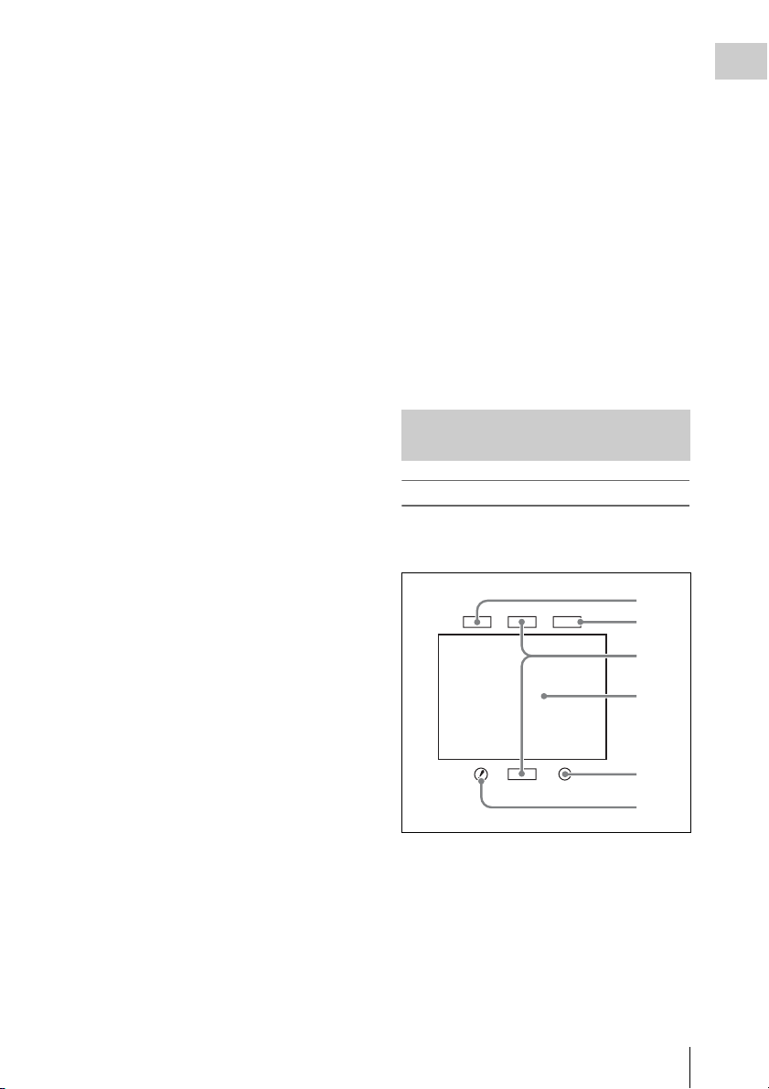
Locations and Functions of Parts and Controls
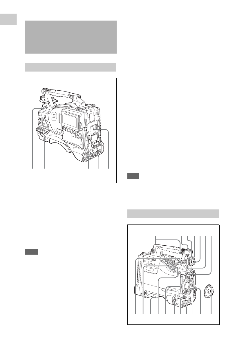
c DC IN (DC power input) connector
(XLR type, 4-pin, male)
To operate the camcorder from an AC power
supply, connect a n optional DC power cord to th is
terminal and then connect the cord to the DC
output terminal of the BC-L70, BC-M150, or
another battery charger.
Power supply
a LIGHT switch
Determines how a video light connected to the
LIGHT connector (see page 13) is turned on and
off.
AUTO : When the POWER switch of the video
light is in the on position, the video light is
turned on automatically while the camcorder
is recording.
MANUAL: You can turn the video light on or off
manually, using its own switch.
Notes
• When this switch is set to AUTO, at the beginning of
the recording, the picture is recorded even though the
lighting may fluctuate until the video light comes on.
If the beginning of the recording is important, you
should set this switch to MANUAL.
• To ensure proper operation of the video light, Sony
recommends the use of the BP-GL95/L80S Battery
Pack with the camcorder.
d DC OUT 12V (DC power output)
connector (4-pin, female)
Supplies power for a WRR-860A/861/862 UHF
Synthesized Diversity Tuner (not supplied)
(maximum 0.5 A).
Do not connect any equipment other than the
UHF Synthesized Diversity Tuner.
e Battery attachment shoe
Attach a BP-GL95/GL65/L60S/L80S Battery
Pack. Alternatively, you can attach an ACDN2B/DN10 AC Adaptor to operate the
camcorder on AC power supply.
For details about how to attach the battery or AC
adaptor, see “Preparing a Power Supply” on page
31. For information about attaching a synthesized
tuner, see “Attaching a UHF portable tuner (for a
UHF wireless microphone system)” on page 41.
Note
For your safety, and to ensure proper operation of the
camcorder, Sony recommends the use of the following
battery packs: BP-GL95, BP-GL65, BP-L60S, and BPL80S.
Accessory attachments
5674231
b POWER switch
Turns the main power supply on and off.
Locations and Functions of Parts and Controls
12
90qaqs qd qgqh qj
qf8
k
Page 13

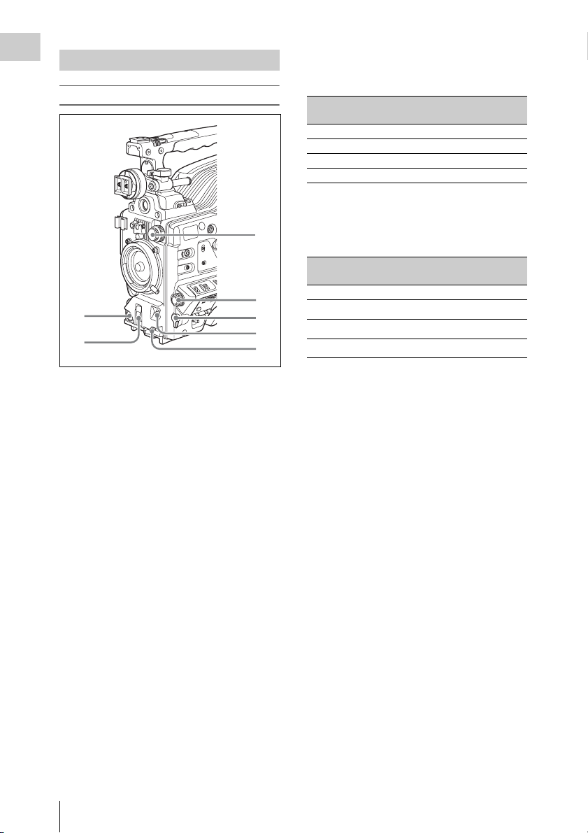
a Shoulder strap fitting
Attach the supplied shoulder strap (see page 45).
b Light fitting shoe
Attach an optional accessory such as a video light
(see page 45).
k LIGHT (video light) connector (2-pin,
female)
A video light with a maximum power
consumption of 50 W, such as the Anton Bauer
Ultralight 2 or equivalent can be connected (see
page 45).
Chapter 1 Overview
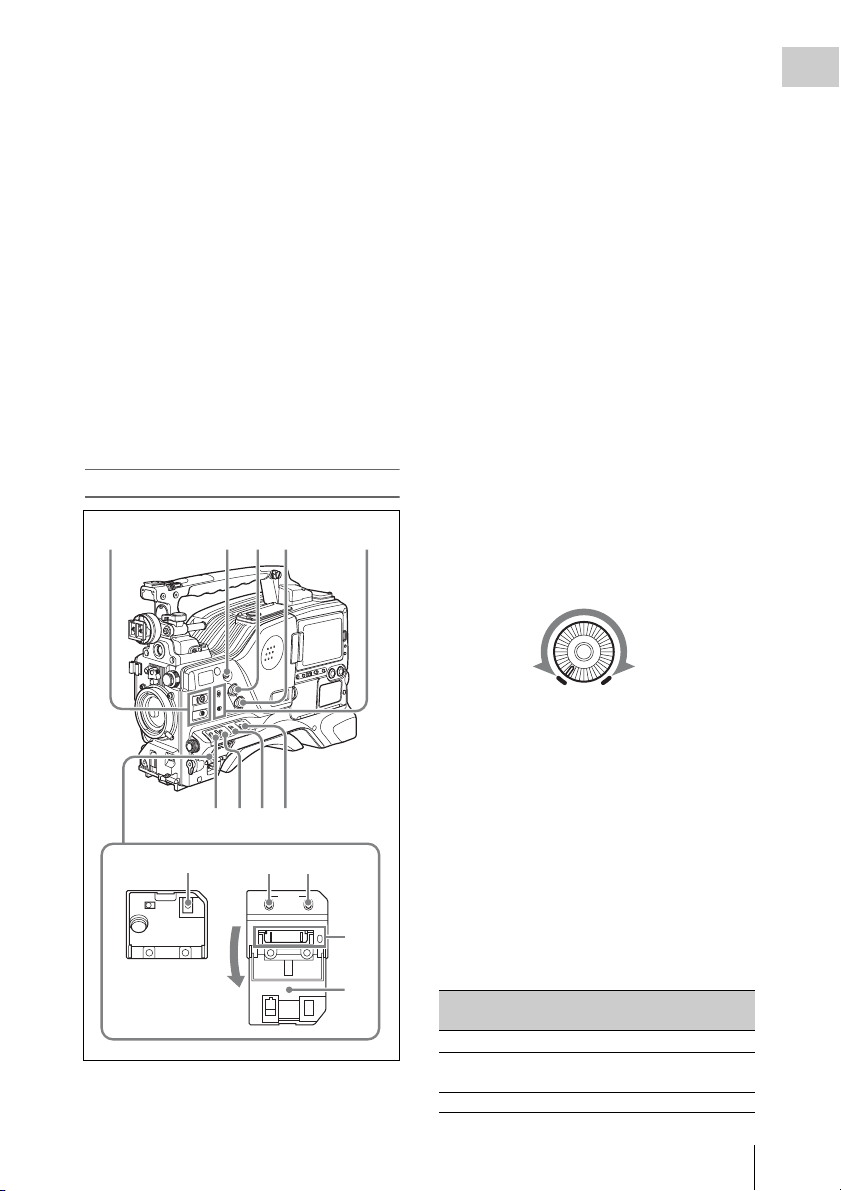
c Viewfinder front-to-back positioning
lever
To adjust the viewfinder position in the front-toback direction, loosen this lever and the LOCK
knob. After adjustment, retighten this lever and
the LOCK knob.
d Viewfinder left-to-right positioning ring
Loosen this ring to adjust the left-to-right position
of the viewfinder (see page 33).
e Viewfinder fitting shoe
Attach an optional viewfinder.
f VF (viewfinder) connector (20-pin)
Connect an optional viewfinder.
Consult a Sony representative for information about
available viewfinders.
g Lens mount securing rubber
After locking the lens in position using the lens
locking lever, fit this rubber over the lower of the
two projections. This fixes the lens mount,
preventing it from coming loose.
h Viewfinder front-to-back positioning
knob (LOCK knob)
Loosen this knob to adjust the front-to-back
position of the viewfinder (see page 33).
i Fitting for optional microphone holder
Fit an optional CAC-12 Microphone Holder (see
page 39).
l Lens cable clamp
Clamp a lens cable.
m MIC IN (microphone input) (+48 V)
connector (XLR type, 5-pin, female)
Connect a stereo microphone to this connector.
The power (+48 V) is supplied via this connector.
n LENS connector (12-pin)
Connect a lens cable to this connector.
Note
Power off this unit before connecting or disconnecting a
lens cable to this connector.
Consult a Sony representative for information about
available lenses.
o Tripod mount
When using the unit on a tripod, attach the tripod
adaptor (optional).
p Lens mount (special bayonet mount)
Attach the lens.
Consult a Sony representative for information about
available lenses.
q Lens locking lever
After inserting the lens in the lens mount, rotate
the lens mount ring with this lever to lock the lens
in position.
After locking the lens, be sure to use the lens
mount securing rubber to prevent the lens from
becoming detached.
j Shoulder pad
Raise the shoulder pad fixing lever to adjust the
position in the front-to-rear direction. Adjust the
position for maximum convenience when
operating the unit on your shoulder.
For details of the adjustment, see “Adjusting the
Shoulder Pad Position” on page 46.
r Lens mount cap
Remove by pushing up the lens locking lever.
When no lens is mounted, keep this cap fitted for
protection from dust.
Locations and Functions of Parts and Controls
13
Page 14
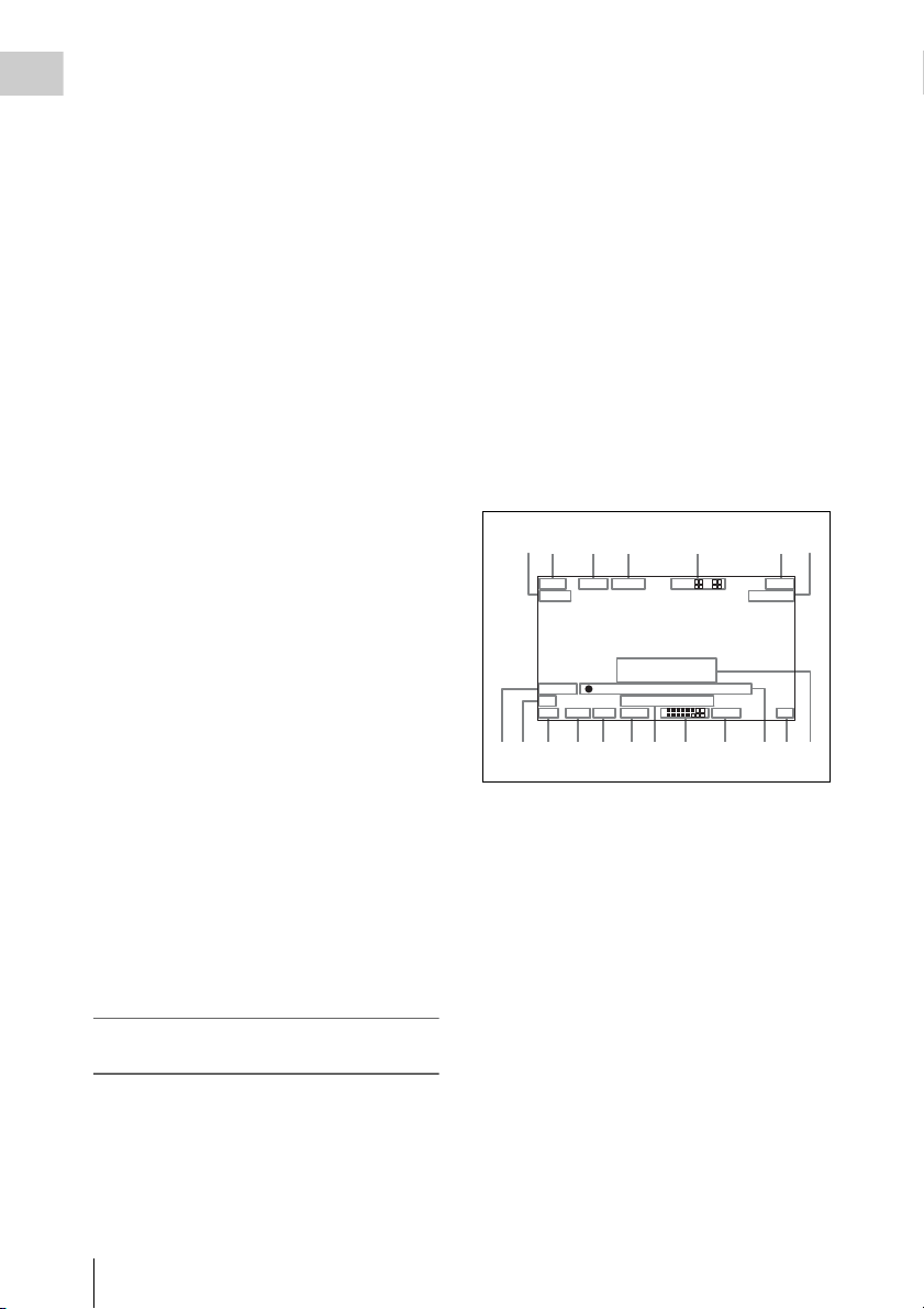
Operating and connectors section
Chapter 1 Overview
Front
1
2
a REC START (recording start) button
Press to start recording. Press it again to stop
recording. The effect is the same as that of the
REC button on the lens.
b SHUTTER selector
Set to ON to use the electronic shutter. Flick to
SELECT to switch the shutter speed or shutter
mode setting within the range previously set with
the menu. When this switch is operated, the new
setting appears on the setting change/adjustment
progress message display area for about three
seconds.
For details about the shutter speed and shutter mode
settings, see “Setting the Electronic Shutter” on
page 52.
c FILTER selector
Selects from the filters built into this unit.
3
4
5
6
7
FILTER selector (outer knob) setting and
Electrical CC (color conversion) filter
selection
FILTER selector
(outer knob) setting
A Cross filter
B 3200K
C 4300K
D 6300K
a) A type of special effect filter that creates a cross of
light in the highlight section.
CC filter selection
a)
FILTER selector (inner knob) setting and ND
filter selection
FILTER selector
(inner knob) setting
1 Clear
2
3
4
ND filter selection
1
/4 ND
1
/16 ND
1
/64 ND
When this selector is used with the menu item for
filter selection display set to ON (see page 131),
the new setting appears on the viewfinder screen
for about three seconds.
For details, see “Adjusting the white balance” on
page 50.
d MENU knob
Changes the page selection or a setting within the
menu.
For details about how to use the MENU knob, see
“Menu Operations” on page 119.
e EARPHONE jack (monaural,
minijack)
You can monitor the E-E
1)
sound during
recording and playback sound during playback.
When an alarm is indicated, you can hear the
alarm sound through the earphone. You can use
this with the EARPHONE jack on the rear of the
unit at the same time. Plugging an earphone into
the jack automatically cuts off the built-in
speaker.
1) E-E: Abbreviation of “Electric-to-Electric”. In E-E
mode, video and audio signals input to the camcorder
are output after passing through internal electric
circuits only. This can be used to check input signals.
Locations and Functions of Parts and Controls
14
Page 15
f AUTO W/B BAL (automatic white/
black balance adjustment) switch
Activates the automatic white/black balance
adjustment functions.
WHITE: Adjusts the white balance
automatically. If the WHITE BAL switch
(see page 16) is set to A or B, the white
balance setting is stored in the corresponding
memory. If the WHITE BAL switch is set to
PRST, the automatic white balance
adjustment function does not operate.
BLACK: Adjusts the black set and black balance
automatically.
g MIC (microphone) LEVEL control
Adjusts the input level of audio channels 1, 2, 3
and 4.
For details, see “Adjusting the Audio Level” on page
57.
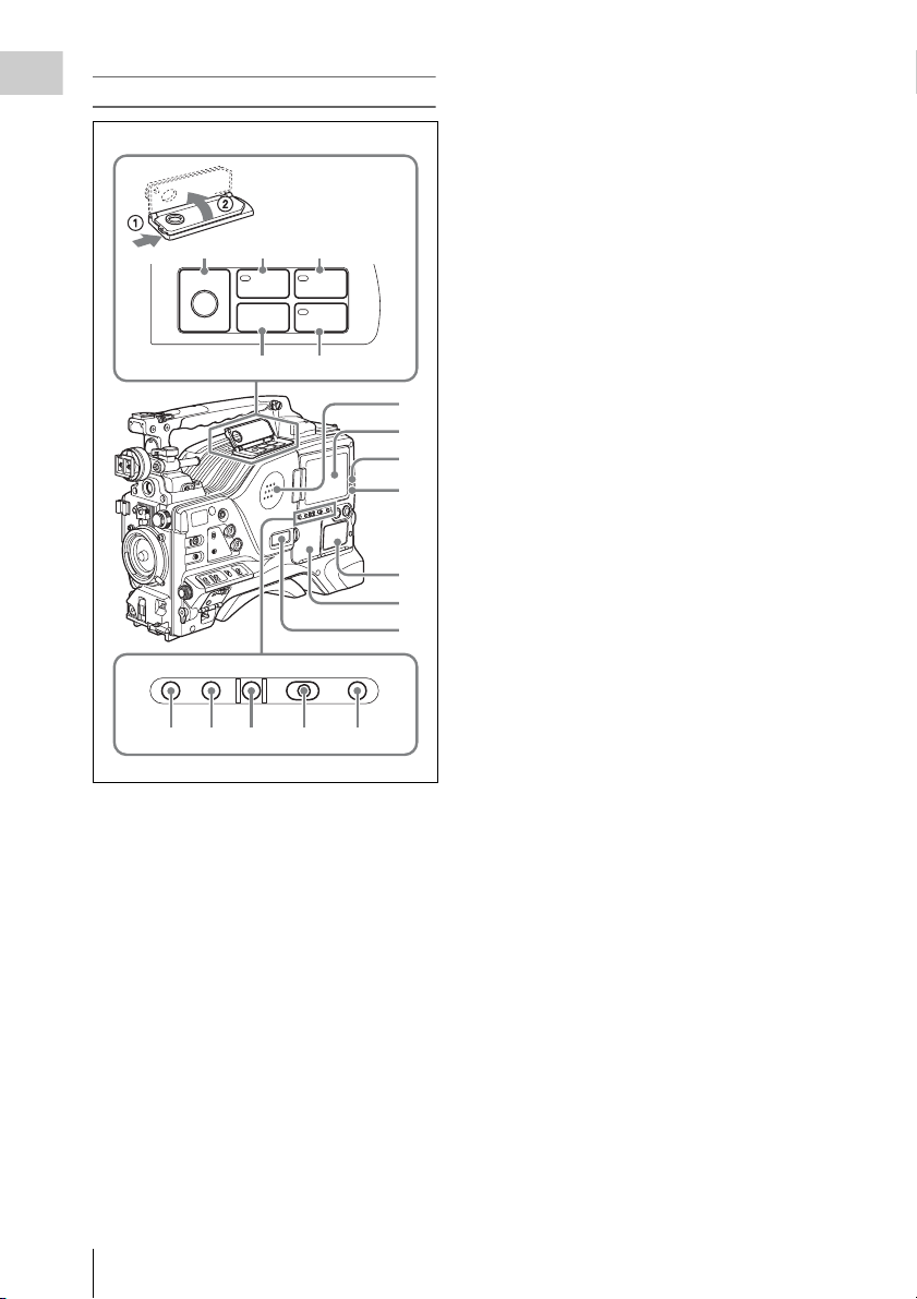
a ASSIGN (assignable) 1/2 switches
You can assign the desired functions to these
switches on the ASSIGNABLE SW page of the
OPERATION menu.
Nothing is assigned to these switches when the
camcorder is shipped from the factory (OFF is
selected in the menu).
For details, see “Assigning functions to ASSIGN
switches” on page 138.
b ASSIGN (assignable) 5 switch
You can assign the desired function to this switch
on the ASSIGNABLE SW page of the
OPERATION menu. The switch lights when
being pressed. Nothing is assigned to the switch
when the camcorder is shipped from the factory
(OFF is selected in the menu).
For details, see “Assigning functions to ASSIGN
switches” on page 138.
Chapter 1 Overview
Right side (near the front)
2341
6789
qa qs0
STATUS
ON/
SEL
OFF
OFF
MENU
CANCEL/PRST
ESCAPEON
qd
qf
5
c ALARM (alarm tone volume
adjustment) knob
Controls the volume of the warning tone that is
output via the built-in speaker or optional
earphones. When the knob is turned to the
minimum position, no sound can be heard.
ALARM
Minimum Maximum
d MONITOR (monitor volume
adjustment) knob
Controls the volume of the sound other than the
warning tone that is output via the built-in speaker
or optional earphones. When the knob is turned to
the minimum position, no sound can be heard.
e MONITOR (audio monitor selection)
switches
By means of combinations of the two switches,
you can select audio that you want to hear through
the built-in speaker or optional earphones.
Position of down-side switch: CH-1/2
Position of up-side
Audio outp ut
switch
CH-1/CH-3 Channel 1 audio
MIX Channels 1 and 2 mixed
audio (stereo)
CH-2/CH-4 Channel 2 audio
Locations and Functions of Parts and Controls
15
Page 16

Position of down-side switch: CH-3/4
Chapter 1 Overview
Position of up-side
switch
CH-1/CH-3 Channel 3 audio
MIX Channels 3 and 4 mixed
CH-2/CH-4 Channel 4 audio
Audio output
audio (stereo)
By connecting stereo headphones to the
EARPHONE jack on the rear of the unit, you can
hear the audio in stereo. (On the AUDIO 1 page
of the MAINTENANCE menu, HEADPHONE
OUT must be set to STREO.)
f VTR SAVE/STBY (standby) switch
Controls the VTR power mode during pauses in
recording.
SAVE: Power saving mode. When you press the
REC START button, there is a short delay
before recording starts, but power
consumption in this mode is less than in
standby mode. As a result, battery life is
extended. When the switch is set to SAVE,
the VTR SAVE indicator in the viewfinder
lights.
STBY: Standby mode. Recording starts as soon
as you press the REC START button.
Notes
• Avoid allowing the camcorder to remain in STBY
(standby) mode for a long time.
• Even if the switch is set to the STBY position, the
camcorder can automatically turn to power saving
mode if the tape does not run for a certain period. In
such a case, the VTR SAVE indicator in the viewfinder
lights. This function is effective when a setting other
than OFF is selected for the STBY OFF TIMER on the
CAM CONFIG 1 page of the MAINTENANCE menu.
The STBY OFF TIMER item also allows you to select
the length of time until the camcorder turns to power
saving mode.
For detailed information, see “Settin g the Rec-Pause
Stand-by Off Timer” on page 82.
g GAIN selector
Switches the gain of the video amplifier to match
the lighting condition s during shooting. The gains
corresponding to the L, M, and H settings can be
selected in the menu. (The factory settings are
L=0 dB, M=6 dB, and H=12 dB.)
When this switch is adjusted, the new setting
appears on the setting change/adjustment
progress message display area of the viewfinder
screen for about three seconds.
For details, see “Setting gain values for the GAIN
selector positions” on page 137.
h OUTPUT/DCC (output signal/dynamic
contrast control) switch
Switches the video signal, which is output to the
VTR, viewfinder, and video monitor from the
camera section, between the following two.
BARS: Outputs the color bar signal.
CAM: Outputs the video signal from the camera.
When this is selected, you can switch DCC
1)
on and off.
1) DCC (Dynamic Contrast Control): Against a very
bright background with the iris opening adjusted to the
subject, objects in the background will be lost in the
glare. The DCC function will suppress the high
intensity and restore much of the lost detail and is
particularly effective in the following cases.
• Shooting people in the shade on a sunny day
• Shooting a subject indoors, against a background
through a window
• Any high contrast scene
i WHITE BAL (white balance memory)
switch
Controls adjustment of the white balance.
PRST: Adjusts the color temperature to the preset
value (the factory default setting: 3200K).
Use this setting when you have no time to
adjust the white balance.
A or B: Recall the white balance adjustment
settings already stored in A or B. Flick the
AUTO W/B BAL switch (see page 15) on th e
WHITE side, to automatically adjust the
white balance, and save the adjustment
settings in memory A or memory B.
You can use the AUTO W/B BAL switch
even when ATW
1)
is in use.
B (ATW): When this switch is set to B and
WHITE SWITCH <B> is set to ATW on the
WHITE SETTING page of the
OPERATION menu, ATW is activated.
When this switch is adjusted, the new setting
appears on the setting change/adjustment
progress message display area of the viewfinder
screen for about three seconds.
1) ATW (Auto Tracing White Balance): The white
balance of the picture being shot is adjusted
automatically for varying lighting conditions.
j STATUS ON/SEL/OFF (menu display
on/page selection/display off) switch
This switch is enabled when the menu is not
displayed.
Locations and Functions of Parts and Controls
16
Page 17

ON/SEL: Each time this switch is pushed
upward, a window to confirm the menu
settings and status of the camcorder appears
on the viewfinder screen. The window
consists of four pages, which are switched
each time the switch is pushed upward. Each
page is displayed for about 10 seconds.
OFF: To clear the page after display, push this
switch down to the OFF position.
You can select the pages to be displayed on the
menu.
For details, see “Displaying the status confirmation
screens” on page 136.
k MENU ON/OFF switch
To use this switch, open the cover.
This switch is used to display the menu on the
viewfinder screen or the test signal screen.
Closing the cover automatically sets this switch to
OFF.
ON: Displays the menu on the viewfinder screen
or the test signal screen.
OFF: Removes the menu from the viewfinder
screen or the test signal screen.
For details, see “Menu Operations” (page 119).
l CANCEL/PRST (preset)/ESCAPE
switch
To enable this switch, set the MENU ON/OFF
switch to ON.
Closing the cover automatically sets the MENU
ON/OFF switch to OFF.
CANCEL/PRST: Flicking this switch up to this
position displays the message to confirm
whether the previous sett ings are cancelled or
settings are reset to their initial values,
depending on the menu operating condition.
Flicking this switch up to this position again
cancels the previous settings or resets the
settings to their initial values.
ESCAPE: Use this switch when the menu page,
which has a hierarchical structure, is opened.
Each time the switch is flicked to this
position, the page returns to one stage higher
in the hierarchy.
m “Memory Stick” compartment
Chapter 1 Overview
Label
“Memory Stick” Access indicator
Open the lid of the menu operating section, and
insert a “Memory Stick”, with the notch facing
downward, in the direction shown by the arrow,
so that it clicks into place.
To remove a “Memory Stick”, first press it in to
release the lock, then withdraw.
The “Memory Stick” access indicator lights in
green when a “Memory Stick” is loaded, and
lights in red when the “Memory Stick” is being
accessed for reading or writing.
For details about “Memory Stick”, see “Handling
the “Memory Stick”” on page 144.
n Cover
Locations and Functions of Parts and Controls
17
Page 18
Right side (near the rear)
Chapter 1 Overview
c WARNING indicator
Lights up or flashes when an abnormality occurs
in the VTR section.
For details about the meaning of the states of the
WARNING indicator, see ““Operation Warnings”
on page 161.
89q;
REW
EJECT
Z
F FWD
m
M
PLAYSTOP
x
N
qa qs
1
2
3
4
5
6
7
BRIGHTDISPLAYRESETHOLDDISP SEL
CTL T DATA
qd qf qg qh qj
a Built-in speaker
The speaker can be used to monitor E-E sound
during recording, and playback sound during
playback. The speaker also sounds alarms to
reinforce visual warnings.
If you connect earphones to the EARPHONE
jack, the speaker output is suppressed
automatically.
For details about alarms, se e “Operation Warnings”
on page 161.
d TAPE indicator
This lights when a cassette is loaded.
e Protection cover of the audio control/
timecode operations sections
Open to access the audio control section and the
timecode operation section.
For details, see “Timecode/menu operations
section and audio control section” on page 23
.
f Protection cover of the timecode/menu
operations section
Open to access the buttons and switches used for
setting timecode and user bit values and
performing menu operations.
For details, see “Timecode/menu operations
section and audio control section” on page 23
.
g Monochrome LCD
This shows the remaining battery capacity,
remaining tape recording time, time data, and so
on.
For details, see “Status displays on the LCD monitor
and monochrome LCD” on page 20.
h EJECT button
Press this button to eject or load a cassette.
i REW (rewind) button and indicator
Press this button to rewind the tape. The indicator
lights during rewinding.
j F FWD (fast forward) button and
indicator
Press this button to fast forward the tape. The
indicator lights during fast forward.
b LCD monitor
Displays camera video, VTR-related warnings,
remaining battery capacity, remaining tape
recording time, audio levels, time data, and so on.
For details, s ee “Status displays on the LCD monitor
and monochrome LCD” on page 20.
Locations and Functions of Parts and Controls
18
k STOP button
Press this button to stop the tape.
l PLAY button and indicator
Press this button to view the recorded picture in
the viewfinder or on the color video monitor. The
indicator lights during playback. The four times
normal speed search function is provided to make
Page 19

it far quicker to find a desired location of the tape.
Press the REW button or F FWD button during
playback to view the four times normal speed
search picture.
m DISP SEL (display selection) button
With each press of this button, the display in the
LCD monitor changes as follows.
Display indication Meaning
Video with
superimposed
information (CHAR)
Video without
superimposed
information (MONI)
Status display
(STATUS)
The LCD monitor displays
the same text information
as the viewfinder.
The video only appears.
Counter indications,
warnings, audio levels, and
similar information appear.
No video image appears.
n HOLD (display hold) button
Pressing this button instantly freezes the time data
displayed in the counter display section. (The
timecode generator continues running.) Pressing
this button again releases the hold.
You can use this button, for example, to
determine the exact time of a particular shot.
For details of the counter display, see page 20.
o RESET button
Resets the value shown in the time counter
display. According to the settings of the PRESET/
REGEN/CLOCK switch (see page 23), the FRUN/SET/R-RUN switch (see page 23), and the
DATA DISPLAY switch (see page 23), this
button resets the display as follows.
Settings of switches To reset
DISPLAY switch:
CTL
DISPLAY switch:
TC
PRESET/REGEN/
CLOCK switch:
PRESET
F-RUN/SET/R-RUN
switch: SET
DISPLAY switch:
DATA
PRESET/REGEN/
CLOCK switch:
PRESET
F-RUN/SET/R-RUN
switch: SET
DATA DISPLAY
switch: U-BIT
a) Of the timecode bits for every frame recorded on the
tape, those bits which can be used to record useful
information for the user such as scene number,
shooting place, etc.
For details, see “Setting the Time Data” on page 60.
CTL to 0:00:00:00
Timecode to 00:00:00:00
User bits data
00
a)
to 00 00 00
p DISPLAY switch
CTL: Displays control signal.
TC: Displays timecode.
DATA: Displays the item selected with the
DATA DISPLAY switch.
For details, see “Status displays on the LCD monitor
and monochrome LCD” on page 20.
q BRIGHT (brightness) button
Switches the brightness of the LCD monitor
backlight, and turns the backlight of the
monochrome LCD on and off.
Each press of the button selects the next setting in
the order shown in the following table.
Chapter 1 Overview
Locations and Functions of Parts and Controls
19
Page 20
Setting LCD monitor
Chapter 1 Overview
backlight
H High (select this to view
Monochrome
LCD backlight
Lit
the LCD monitor
outdoors in the
daytime)
M Brightness between H
Lit
and L
L Low (select this to view
Lit
the LCD monitor
indoors or outdoors at
night)
OFF Off (the display is also
Off
off)
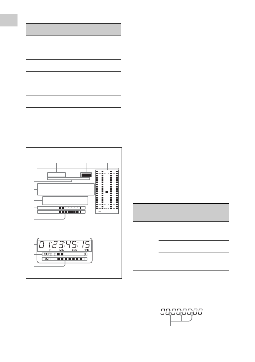
Status displays on the LCD monitor and
monochrome LCD
The following displays appear on the LCD
monitor and monochrome LCD when STATUS is
selected with the DISP SEL button.
123
59.94i
4
5
6
7
8
PB NDF EXT LK21HOLD
.....
01
23 45 15
H
RF1 RF2 SERVO
HUMID SLACK
TAPE E B
BATT EF
MIN SEC FRM
LCD monitor
EMPH
.
5
7
8
Monochrome LCD
a Frame frequency
Indicates the currently selected frame frequency.
59.94i: 59.94 fields per second, interlace scan
mode
50i: 50 fields per second, interlace scan mode
25PsF: 25 frames per second, progressive scan
mode (HDW-650P only)
23.98PsF: 23.98 frames per second,
progressive scan mode (HDW-650F only)
b Emphasis display
Lights during recording or playback when
emphasis processing is performed on audio
signals.
c Audio level indicators
Indicates the audio recording or playback levels
of channels 1 to 4.
d Status display
PB: Appears when the tape is running.
NDF: Appears when non-drop-frame timecode is
selected.
EXT-LK: Appears when the internal timecode
generator is locked to an external signal input
to the TC IN (timecode input) connector.
HOLD: Appears when the internal timecode
generator is stopped.
e Time counter display
Displays timecode, CTL signals, user bits or the
real time. Except when the timecode is being set,
the information displayed is determined by the
settings of the DISPLAY and DATA DISPLAY
OVER
0
10
20
30
40
dB
ST
PEAK
switches.
For more information about timecode, see “Setting
the timecode” (page 60).
Switch settings related to timecode and
displayed information
43
DISPLAY
switch
position
DATA
DISPLAY
switch position
Displayed
information
CTL Any position Control signal
TC Any position Timecode
DATA U -BIT User bits
SHOT TIME Data and time
from shot data
SHOT-NO Time counter is
not used (currently
zero is displayed)
When the HOLD button is pressed to hold the
timecode value, the timecode is displayed in the
format shown below. When the HOLD button is
pressed again to release the hold, the timecode is
displayed in the normal format.
Lights when the HOLD button is pressed.
Locations and Functions of Parts and Controls
20
Page 21

f Warning indicator area
Displays warnings when trouble with recording
or moisture condensation occurs.
For details, see “Operation Warnings” on page 161.
Chapter 1 Overview
Locations and Functions of Parts and Controls
21
Page 22

g Remaining tape recording time indicator
Chapter 1 Overview
Indication Remaining recording time
TAPE E [x x x x x x x] B More than 30 minutes
TAPE E [x x x x x x ] B 25 to 30 minutes
TAPE E [x x x x x ] B 20 to 25 minutes
TAPE E [x x x x ] B 15 to 20 minutes
TAPE E [x x x ] B 10 to 15 minutes
TAPE E [x x ] B 5 to 10 minutes
TAPE E [x ]
TAPE E [x ] B (flashing)
B 2 to 5 minut
a)
0 to 2 minutes
TAPE E [ ] B (flashing) 0 minutes
a) During recording
h Remaining battery capacity indicator
es
Indication Battery voltage
BP-L90A/L60S/L80S
Other batteries
BATT E [ x x x x x x x] F 15.5 V or more 17.0 V or more
BATT E [ x x x x x x ] F 15.1 to 15.5 V 16.0 to 17.0 V
BATT E [ x x x x x ] F 14.6 to 15.1 V 15.0 to 16.0 V
BATT E [ x x x x ] F 13.8 to 14.6 V 14.0 to 15.0 V
BATT E [ x x x ] F 12.9 to 13.8 V 13.0 to 14.0 V
BATT E [ x x ] F 12.0 to 12.9 V 12.0 to 13.0 V
BATT E [ x ]
F 10.8 to
12.0 V 11.0 to 12.0 V
BATT E [ ] F 10.8 V or less 11.0 V or less
a) You can change the threshold voltages on the
BATTERY 2 page of the MAINTENANCE menu
(see page 104).
Indication Battery voltage
BP-GL95/GL65/IL75/M100, Anton Bauer Battery
System
BATT E [ x x x x x x x] F 80 to 100%
BATT E [ x x x x x x x] 70%
BATT E [ x x x x x x ] 60%
BATT E [ x x x x x ] 50%
BATT E [ x x x x ] 40%
BATT E [ x x x ] 30%
BATT E [ x x ]
BATT
E [x ] 10%
20%
BATT E [ ]0%
a)
Locations and Functions of Parts and Controls
22
Page 23

Timecode/menu operations section and audio
67890
control section
1234 5
LEVEL
CANCEL/PRST
U BIT
SHOT
MENU
DATA DSPLAY
ENTER
CUE IN
CH 1
TIME
MX
NO
CH 2
010010
F-RUN
SET
R-RUN
CH 1
PRESET
REGEN
CLOCK
AUTO
MANUAL
AUDIO SELECT
AUDIO N
FRONT
REAR
WIRELESS
CH 3
F
R
W
CH 2
CH 4
F
R
W
a MENU button
When pressed, enables menu operations with the
arrow keys, the CANCEL/PRST button, and the
ENTER button.
The menu appears temporarily, even when the
MENU ON/OFF switch is in the OFF position.
For details, see “Menu Operations” (page 119).
F-RUN: Timecode keeps advancing, regardless
of the operating state of the VTR. Use this
setting when synchronizing the timecode
with an external timecode.
SET: Sets the timecode or user bits.
R-RUN: Timecode advances only during
recording. Use this setting to have a
consecutive timecode on the tape.
For details, see “Setting the timecode” on page 60
and “Setting the user bits” on page 60.
e AUDIO LEVEL CH-1/CH-2 (audio
channel 1/2 recording level) knobs
Adjusts the audio levels to be recorded on
channels 1 and 2 when the AUDIO SELECT CH1/CH-2 switches (see page 24) are set to
MANUAL.
f DATA DISPLAY switch
U-BIT: Displays the user bit value.
SHOT TIME: Displays the date and time from
the shot data.
SHOT-NO: Time counter is not used.
Chapter 1 Overview
b ENTER button and arrow buttons
Use to set timecode and user bit values, and for
menu screen operations.
Select items and change their values with the
arrow buttons, and confirm with the ENTER
button for menu screen operations.
When setting timecode and user bits, use the right
and left arrow buttons to select the digit to modify
(the selected digit flashes), and use the up and
down arrow buttons to increment and decrement
the flashing digit.
c CANCEL/PRST (menu cancel/preset)
button
This button is also enabled when the MENU
button is pressed to enable arrow key operations.
Cancels changes to a menu setting, or resets one
or more settings to the default settings. A message
appears so that you can confirm the cancellation
or reset. Press again to confirm the cancellation or
reset.
d F-RUN/SET/R-RUN (free run/set/
recording run) switch
Selects the operating mode of the internal
timecode generator. The operating mode is set as
explained below, depending on the position of the
switch.
g CUE IN(cue track input) switch
Selects the input signal to be recorded on the cue
track.
CH-1: Signal selected by the AUDIO IN CH-1
switch
MIX: Mixed signals selected by the AUDIO IN
CH-1 and CH-2 switches
CH-2: Signal selected by the AUDIO IN CH-2
switch
Note
When recording mixed signals by setting this switch to
MIX, be sure to confirm that the emphasis settings of the
two channels (on/off) are the same. If they are different,
the camcorder cannot record or play back mixed signals
correctly.
When the AES/EBU format audio signal is selected, the
emphasis settings are determined by the channel status of
the AES/EBU format audio signal (emphasis bit).
When an audio signal other than the AES/EBU format
audio signal is selected, the emphasis setting depends on
the setting of AU REC EMPHASIS (see page 105) on
the AUDIO 2 page of the MAINTENANCE menu.
Use this in combination with other buttons.
h PRESET/REGEN (regeneration)/
CLOCK switch
Selects whether to set a new timecode or to utilize
the existing timecode.
PRESET: Records a new timecode.
Locations and Functions of Parts and Controls
23
Page 24
REGEN: Records timecode continuous with the
Chapter 1 Overview
existing timecode recorded on the tape.
Regardless of the setting of the F-RUN/SET/
R-RUN switch, the camcorder operates in RRUN mode.
CLOCK: Records timecode synchronized to the
internal clock. Regardless of the setting of
the F-RUN/SET/R-RUN switch, the
camcorder operates in F-RUN mode.
i AUDIO SELECT CH-1/CH-2 (audio
channel 1/2 adjustment method
selection) switches
Select the audio level adjustment method for each
of audio channels 1 and 2.
AUTO : Automatic adjustment
MANUAL: Manual adjustment
j AUDIO IN CH-1/CH-2/CH-3/CH-4
(audio channel 1/2/3/4 input selection)
switches
AUDIO IN CH-1/CH-2 switches
Select the audio input signals to be recorded on
audio channels 1 and 2.
FRONT: Audio input signals from the
microphone connected to the MIC IN
connector
REAR: Audio input signals from an audio device
connected to the AUDIO IN CH-1/CH-2
connectors
WIRELESS: Audio input signals from the UHF
portable tuner (supplied separately) if it is
installed
AUDIO IN CH-3/CH-4 switches
Select the audio input signals to be recorded on
audio channels 3 and 4.
F (FRONT): Audio input signals from a
microphone connected to the MIC IN
connector
R (REAR): Audio input signals from an audio
device connected to the AUDIO IN CH-1/
CH-2 connectors
W (WIRELESS): Audio input signals from the
UHF portable tuner (supplied separately) if it
is installed
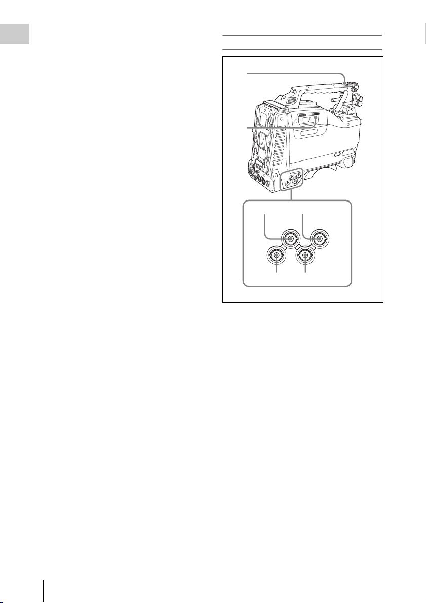
Left side and upper section
1
2
34
GEN LOCK
N
TEST
OUT
TC OUT
56
a ASSIGNABLE 3/4 switches
You can assign the desired functions to these
switches on the ASSIGNABLE SW page of the
OPERATION menu.
Nothing is assigned to these switches when the
camcorder is shippe d from the factory (equivalent
to a selection of OFF in the menu).
For details, see “Assigning functions to ASSIGN
switches” on page 138.
b Lid of the cassette compartment
This opens when the EJECT button on the top
panel is pressed. Press the side of the lid to close.
c GEN LOCK IN (genlock signal input)
connector (BNC type)
• This connector inputs a reference signal when
the camera is to be genlocked or when timecode
is to be synchronized with external equipment.
Use the GENLOCK page of the
MAINTENANCE menu to adjust the genlock
H-phase (phase of horizontal sync signal).
• This connector also inputs a return video signal.
The HD-Y signal can be displayed in the
viewfinder screen wh ile holding the RET button
TC IN
Locations and Functions of Parts and Controls
24
Page 25
down with RETURN VIDEO set to ON on the
ASSIGNABLE SW page of the OPERATION
menu.
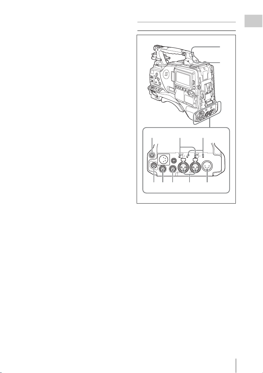
Rear
Chapter 1 Overview
d TC IN (timecode input) connector
(BNC type)
To apply an external lock to the timecode of this
unit, input the reference timecode.
For details of timecode, see “Setting the timecode”
on page 60.
e TEST OUT connector (BNC type)
This connector outputs the video signal for a
video monitor. The output signal can be selected
from composite video, HD-Y, R, G, and B. To
switch output signals, use the TEST OUT
SELECT item on the OUTPUT 1 page of the
OPERATION menu.
If the output signal is set to one of R, G, or B, then
this setting changes to HD-Y when the camcorder
is powered off and on again.
Depending on menu settings, menus, timecode,
and shot data can be superimposed on the image
on the monitor. This connector can also be used to
synchronize the timecode of an external VTR
with the timecode of the camcorder.
f TC OUT (timecode output) connector
(BNC type)
To lock the timecode of an external VTR to the
timecode of this unit, connect this connector to
the external VTR’s timecode input connector.
1
2
345
AU O IN
A EBU
LNE MIC
DC OUT
12V
HDS OUT
HD/SD S OUT
05A
CH1
DC
N
SEBU
LIN MIC
48V
8V
OFF
OFF
AUDO OUT
CH2
67 8 9 0
a TALLY (back tally) indicator (red)
Lights up during recording. It will not light if the
TALLY switch is set to OFF. This indicator also
flashes to indicate warnings (see page 18) in the
same manner as the REC/TALLY indicator in the
viewfinder.
For details, see “Operation Warnings” on page 161.
b TALLY switch
Set to ON to activate the TALLY indicator
function.
c EARPHONE jack (stereo, minijack)
You can monitor the E-E sound during recording
and playback sound during playback. When an
alarm is indicated, you can hear the alarm sound
through the earphone. You can use this with the
EARPHONE jack on the front of the unit at the
same time. Plugging an earphone into the jack
automatically cuts off the built-in speaker.
You can select monaural or stereo on the
AUDIO 1 page of the MAINTENANCE menu.
Locations and Functions of Parts and Controls
25
Page 26
d LINE /AES/EBU / MIC selectors
q
These select the audio source of the audio input
Chapter 1 Overview
signals input to the AUDIO IN CH1/CH2
connectors.
LINE: Line input audio equipment
AES/EBU: AES/EBU format audio signal
MIC: Microphone input
Note
When either of these selectors is in the MIC position, and
the corresponding +48V/OFF switch is in the +48V
position, and you inadvertently connect any audio device
other than a microphone to the corresponding connector
(AUDIO IN CH1 or CH2), the connected device may be
damaged.
e +48V/OFF switches
Select either of the following positions for the
microphones to be connected.
+48V: For a microphone that uses an external
power supply
OFF: For a microphone that uses an internal
power supply
f REMOTE connector (8-pin)
Connect an RM-B150/B750 Remote Control
Unit, which makes it possible to control the
camcorder remotely.
Note
Before connecting/disconnecting the Remote Control
Unit to/from the camcorder, be sure to turn off the
camcorder POWER switch.
g HDSDI OUT connector (BNC type)
Outputs an HDSDI signal (with embedded
audio).
h HD/SD SDI OUT connector (BNC type)
Outputs an HDSDI or SDSDI signal (with
embedded audio). To switch between HDSDI and
SDSDI output, use the HD/SD SDI OUT item on
the OUTPUT 1 page of the OPERATION menu.
Setting menus, timecode, or shot data can be
superimposed on the camera output video
depending on the menu settings, and you can
view them on the monitor screen.
i AUDIO IN CH1/CH2 (audio channel-1
and channel-2 input) connectors (XLR
type, 3-pin, female)
These are audio input connectors for channels 1
and 2 to which you can connect audio equipment
or a microphone.
When the LINE / AES/EBU / MIC selectors are
set to LINE or MIC, the CH1 connector is used
for channel-1 and -3 inputs, and the CH2
connector for channel-2 and -4 inputs.
When the LINE / AES/EBU / MIC selectors are
set to AES/EBU, the CH1 connector is used for
channel-1 and -2 inputs, and the CH2 connector,
for channel-3 and -4 inputs.
j AUDIO OUT connector (XLR type, 5-
pin, male)
Outputs the audio signals recorded on audio
channels 1 and 2 or audio channels 3 and 4. The
audio signals are selected by the MONITOR
switches.
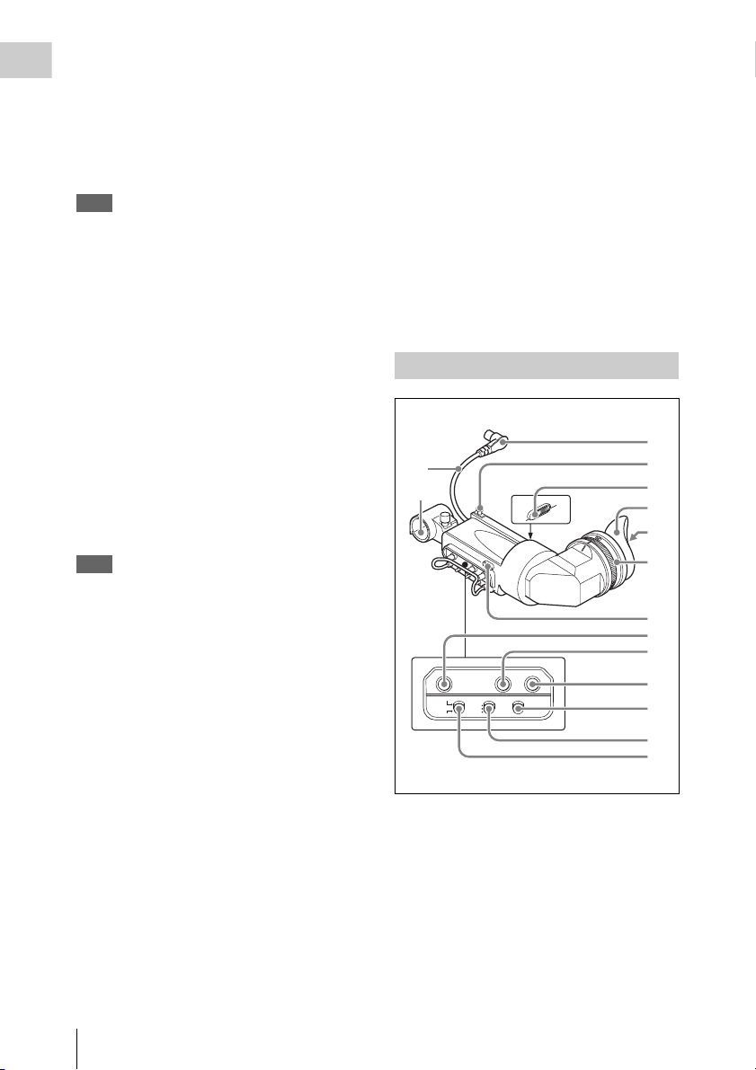
HDVF-20A viewfinder (optional)
1
qf
qg
PEAK NG CONTRAST BRIGHT
DSPLAY
ASPECT
TALLY
ZEBRA
HIGH
ON
OFF
OFF
LOW
MOMENT
a Plug
Connect to the VF connector on the camcorder.
b Stopper
Prevents the viewfinder from coming off the
camcorder when it is slid from side to side.
c Camera operator tally indicator
Lights up while camcorder is recording. This
indicator can be covered when not in use.
2
3
4
5
6
7
8
9
0
qa
qs
d
Locations and Functions of Parts and Controls
26
Page 27
This indicator also flashes to indicate warnings, in
6
the same manner as the tally indicator and the
REC indicator in the viewfinder.
d Eyecup
e Indicators and status display
For details, see “Status display on the viewfinder
screen” on page 27.
f Diopter adjustment ring
Allows for optimal focus adjustment.
g Tally indicator
Lights up while camcorder is recording. Set the
TALLY switch to OFF when not in use. The
brightness can also be adjusted with the TALLY
switch.
This indicator also flashes to indicate warnings, in
the same manner as the camera operator tally
indicator and the REC indicator in the viewfinder.
h PEAKING control
Turning this control clockwise adjusts the picture
sharpness, and makes focusing easier. This
control has no effect on the output signals of the
camcorder.
i CONTRAST control
Adjusts the contrast of the screen. This control
has no effect on the output signals of the
camcorder.
j BRIGHT control
Adjusts the brightness of the screen. This control
has no effect on the output signals of the
camcorder.
m DISPLAY/ASPECT switch
Turns the marker indication on and off, and
switches between 4:3 and 16:9 aspect ratios for
viewfinder screen display.
DISPLAY: When the marker indication is
enabled with the camcorder, the marker
indication on the viewfinder screen turns on
and off every time you push the switch up to
this position.
ASPECT: Each push of the switch down to this
position toggles the mask display on and off.
(Make mask display settings on the
MARKER 1 page of the OPERATION menu
(see page 90).)
n Viewfinder cable
o Microphone holder
Status display on the viewfinder screen
Indicators
The following indicators are arranged above and
below the viewfinder screen to show the current
state and adjustments of the camcorder.
TALLY/REC
BATT
1
2
3
4
Chapter 1 Overview
k TALLY switch
Controls the tally indicator located on the front of
the viewfinder.
HIGH: The tally indicator brightness is set to
high.
OFF: The tally indicator is disabled.
LOW: The tally indicator brightness is set to low.
l ZEBRA (zebra pattern) switch
Controls the zebra pattern display on the
viewfinder screen as follows.
ON: A zebra pattern appears and stays.
OFF: The zebra pattern disappears.
MOMENT: A zebra pattern appears and stays for
about five seconds.
VTR
SAVE
5
a TALLY (green tally) indicator
Lights when the camcorder is in Picture Cache
mode, and flashes when it is in Auto Interval Rec
or Manual Interval Rec mode. Also, lights in
green when the HDW-250/S280 connected to the
HDSDI OUT connector starts recording, if
HDSDI REMOTE I/F on the CAM CONFIG 2
page of the MAINTENANCE menu is set to GTLY.
Locations and Functions of Parts and Controls
27
Page 28
b BATT (battery) indicator
This indicator starts flashing when the battery
Chapter 1 Overview
connected to the camcorder is nearly exhausted,
and stays lit when the battery is completely
exhausted.
To prevent interruption during operation, replace
the battery as soon as this indicator starts flashing.
The battery power level at which the indicator starts
flashing can be set on the BATTERY 1 page of the
MAINTENANCE menu. For details, see page 103.
c REC (recording, red tally) indicator
Lights up while camcorder is recording.
This indicator also flashes to indicate warnings, in
the same manner as the tally indicator and the
camera operator tally indicator.
d Viewfinder screen
e VTR SAVE indicator
This indicator lights when the VTR SAVE/STBY
switch is set to SAVE, putting the VTR into
power save mode.
f ! (warning) indicator
This indicator lights when any of the following
conditions occurs with the corresponding item set
to ON on the ‘!’ LED page of the OPERATION
menu.
• The gain is set to other than 0 dB.
• The SHUTTER selector is set to ON.
• The WHITE BAL switch is set to PRST.
• The electric CC filter is ON.
• ATW is enabled.
• The lens extender is used.
• The reference value of auto iris adjustment is
not the standard value.
The conditions that cause the indicator to light
can be changed on the ‘!’ LED STD page of the
OPERATION menu.
For details, see “Selecting the conditions that light
the ‘!’ (warning) indicator” (page 131).
Layout of the status display on the
viewfinder screen
The viewfinder screen displays not only the video
picture but also characters and messages
indicating the camcorder settings and operating
status, a center marker, a safety zone marker, etc.
When the menu screen is not displayed and the
DISPLAY of the DISPLAY/ASPECT switch is
set to ON, the items for which an ON setting was
made on the VF DISP 1, VF DISP 2, or VF DISP
3 page of the OPERATION menu or with related
switches are displayed at the top and bottom of
the screen.
The messages that give details of the settings and
adjustment progress and results can also be made
to appear for about three seconds while settings
are being changed, during adjustment, and after
adjustment.
For details about the display item selection, see
“Selecting the display items” on page 130.
For details about setting change and adjustment
progress messages, see “Change confirmation/
adjustment progress messages” on page 131.
For details about marker display, see “Setting the
marker display” on page 133.
All items that can be displayed on the viewfinder
screen are shown below.
12 3 45 67
EX Z
MIX DC IN
AWB:NG
OVER LEVEL
REC2 TCG 00:30:11:03
5600
LOW LIGHT
1A
0qsqdqfqg qkqjqh ql
89 qa
13.9
K+ W
99
18 F 30dB 1/ 2000
W:A
13.4
1 2
1
2
V
F1.7
a Playback mix
“MIX” appears when the playback mix function
is set to ON.
b Extender
Displays the extender settings of this unit and the
lens.
EX: The lens extender is on.
08: The lens shrinker is on.
x2D: This unit’s extender function is on.
Ex2D: The lens extender and the digital extender
function of this unit are both on.
c Zoom position
Indicates the zoom position of the zoom lens in
the range from 0 to 99.
Locations and Functions of Parts and Controls
28
Page 29

d Color temperature
Displays a color temperature calculated from the
gain of R and B, in the range 0.0 K to 99.9 K (in
steps of 0.1 K). The +/– signs may be displayed
depending on the OFFSET WHT setting (see
page 140).
No display: OFFSET WHT is OFF
+: The value of OFFSET WHT is greater than
3200K.
–: The value of OFFSET WHT is less than
3200K.
e Wireless microphone reception level
When a UHF portable tuner is installed in the
camcorder, “W” appears together with foursegment reception level indicators for each of the
channels (1 or 2 channels) of the tuner. The
indications are as follows.
Normal use: The number of white segments
indicates the strength of the signal level.
Muted: The number of gray segments indicates
the strength of the signal level.
Reception level over peak: “P” is displayed
instead of the indicators.
1)
Tuner battery is low: The channel number and
indicator of the corresponding channel
1)
flash.
1) DWR-S01D only
f Power source voltage/battery
remaining capacity
When the unit is powered from a battery pack,
indicates the remaining capacity of the power
source voltage. When the unit is powered from a
battery connected to the DC IN connector or AC
adaptor attached to the battery attachment shoe,
indicates the power source voltage.
g External battery
Appears if the power is supplied from an AC
adaptor connected to the DC IN connector.
h External device control
Flashes when recording operation by the external
device connected to the HDSDI OUT connector
is being controlled.
However, this indicator only appears when
HDSDI REMOTE I/F on the CAM CONFIG 2
page of the MAINTENANCE menu is set to
CHARA and HD SDI OUT on the OUTPUT 1
page of the OPERATION menu is set to HDSDI.
i Electric CC (color temperature) filter
Displays the color temperature when the electric
CC filter is ON.
j Filter
Indicates the currently selected filter type (see
page 14).
k White balance memory
Indicates the currently selected white balance
automatic adjustment memory.
A: Displayed when the WHITE BAL switch is set
to A.
B: Displayed when the WHITE BAL switch is set
to B.
P: Displayed when the WHITE BAL switch is set
to PRST or when the preset button on an RMB150 has been pressed.
T: Displayed when ATW is being used.
l Gain value
Indicates the gain value (in dB) of the video
amplifier, as set by the GAIN selector.
m Shutter speed
Indicates the shutter speed or the shutter mode.
However, if the SHUTTER selector (see page 14)
is set to OFF, nothing is displayed.
For details of the displayed shutter speed, see
“Setting the Electronic Shutter” on page 52.
n Operation/alarm message display area
For details, see “Operation/alarm messages” on
page 164.
o Audio level
Indicates the level of audio channel 1 and channel
2. The peak indication of the VTR level meter is
related as follows to the audio level.
1
2
3
-40 -30 -20 -17 -14(dB)
1Audio channel 1 level indicator
2Audio channel 2 level indicator
3VTR level meter indicator
p Remaining tape recording time
Indicates the remaining recording time (in
minutes) of the tape.
Chapter 1 Overview
Locations and Functions of Parts and Controls
29
Page 30

Examples of remain ing recording time indication
Chapter 1 Overview
Indication Remaining recording
F-30 All to 30 minutes
30-25 30 minutes to 25 minutes
25-20 25 minutes to 20 minutes
20-15 20 minutes to 15 minutes
15-10 15 minutes to 10 minutes
time
q Timecode
Indicates the elapsed recording/playback time,
timecode, user bits or other information selected
by the DISPLAY switch (see page 19) and the
DATA DISPLAY switch (see page 23).
r Iris setting/auto iris override
Indicates the F value (iris setting) of the lens.
Auto iris override is shown by an indicator made
up of two segments each on the upper and lower
sides.
For details, see “Changing the Reference Value for
Automatic Iris Adjustment” on page 55.
s Setting change and adjustment
progress message display area
For details, see “Change confirmation/adjustment
progress messages” on page 131.
Locations and Functions of Parts and Controls
30
Page 31

Chapter2 Preparations
Preparing a Power Supply
For safety, use only the Sony battery packs listed
below.
• BP-GL95/GL65/L60S/L80S Lithium-ion
Battery Pack
• AC power using the AC-DN2B/DN10 AC
adaptor
Using a battery pack
When a BP-GL95/GL65/L60S/L80S Battery
Pack is used, the camcorder will operate
continuously for the time shown below.
Model name Operating time
BP-GL95 Approx. 120 minutes
BP-GL65 Approx. 70 minutes
BP-L60S Approx. 70 minutes
BP-L80S Approx. 95 minutes
Note
The battery pack operating time depends on the
frequency of use of the battery pack, and the ambient
temperature when used.
Before use, charge the battery pack with a charger
suitable for each battery.
For details on the battery charging procedure, refer
to the battery charger operation manual.
Note on using the battery pack
A warm battery pack may not be able to be fully
recharged.
To attach the battery pack
1 Press the battery pack against the back
of the camcorder, aligning the line on
the side of the battery pack with the
matching line on the camcorder.
Chapter 2 Preparations
1
2
1BP-GL95/GL65/L60S/L80S
2Align these lines.
2 Slide the battery pack down until its
“LOCK” arrow points at the matching
line on the camcorder.
1
2
1“LOCK” arrow
2Matching line on the camcorder
Note
If the battery pack is not attached correctly, the terminal
may be damaged.
To detach the battery pack
Holding the release button in, pull the battery
pack up.
Preparing a Power Supply
31
Page 32

Attaching the Viewfinder
Chapter 2 Preparations
Release button
Notes
• During recording and playback, be careful never to
remove the battery pack.
• Make sure to power the camcorder off before replacing
the battery pack.
Using AC power
When using the AC-DN10 AC adaptor
Mount an AC-DN10 on the camcorder in the
same way as a battery pack, then connect to the
AC power supply.
The AC-DN10 can supply up to 100 W of power.
To an AC outlet
CAUTION
When the viewfinder is attached, do not leave the
camcorder with the eyepiece facing the sun. Direct
sunlight can enter through the eyepiece, be focused in the
viewfinder and cause fire.
Note
The viewfinder is supplied separately.
Attaching the HDVF-20A/C35W
Note
When attaching the viewfinder, make notes of the
following points.
• Be sure to the power off the camcorder before coupling
the viewfinder connector to the camcorder’s VF
connector. If you make this connection when the
camcorder power is on, the viewfinder may not
function properly.
• Couple the viewfinder connector firmly to the
camcorder’s VF connector. If the coupling is loose,
noise may appear on the video or the tally indicator
may not operate properly.
For more information about the connection of the
viewfinder and camcorder, contact a Sony service
representative.
1 1 Loosen the viewfinder left-to-right
positioning ring, 2 attach the
viewfinder to the viewfinder fitting
shoe, and 3 tighten the viewfinder leftto-right positioning ring.
Attaching the Viewfinder
32
Page 33

Viewfinder left-to-right positioning ring
Stopper
31
2
Viewfinder left-to-right positioning ring
Chapter 2 Preparations
Viewfinder front-to-back positioning knob
2 Couple the viewfinder connector to the
VF connector.
VF connector
Detaching the viewfinder
You can carry out this by following the attaching
procedure in reverse order, but there is an
additional action to take: when detaching the
viewfinder from the fitting shoe, pull up the
stopper.
Adjusting the viewfinder position
To adjust the viewfinder left-right position,
loosen the left-right positioni ng ring, and to adjust
the front-back position, loosen the front-to-back
positioning knob.
Moving the viewfinder shoe up
1 Loosen the viewfinder front-to-back
positioning lever and the viewfinder
front-to-back positioning knob, and
then pull the viewfinder slide assembly
forward.
2 Using a 2.5 mm diameter hexagonal
wrench, detach the viewfinder slide
assembly and handle front cover.
Attaching the Viewfinder
33
Page 34

Handle front cover
Bolt with
Chapter 2 Preparations
Viewfinder slide assembly
hexagonal hole
3 Attach the handle front cover with the
bottom edge up.
To attach the viewfinder
at the top
Using the BKW-401 Viewfinder Rotation
Bracket
By fitting a BKW-401 Viewfinder Rotation
Bracket (not supplied), you can rotate the
viewfinder out of the way so that your right leg
does not hit the viewfinder while you are carrying
the camcorder.
For details, refer to the operation manual for the
BKW-401.
Detaching the eyepiece
Removing the eyepiece gives a clearer view of the
screen from further away. It is also easy to
remove dust from the viewfinder screen and
mirror when the eyepiece is detached.
1 Turn the eyepiece locking ring fully
counterclockwise, to align the red
marks on the locking ring and the
viewfinder barrel.
1
To attach the viewfinder
at the bottom (factory
default)
4 Attach the viewfinder slide assembly,
reversing the steps of the removal
procedure.
Attaching the Viewfinder
34
23
1Locking ring
2Locking ring match mark
3Match mark on the viewfinder barrel
2 Detach the eyepiece.
Match mark on end of eyepiece
Page 35

To reattaching the eyepiece
1 Align the red marks on the eyepiece
locking ring and the viewfinder barrel.
1 2 3
PEAKING CONTRAST BRIGHT
2 Align the red mark on the end of the
eyepiece end with the red marks on the
eyepiece locking ring and the
viewfinder barrel. Then insert the
eyepiece into the viewfinder barrel.
3 Turn the eyepiece locking ring
clockwise until its “LOCK” arrow
points at the red mark on the viewfinder
barrel.
When the eyecup is worn out, replace it with a
new one.
For details of a replacement eyecup, contact a Sony
service representative.
Adjusting the viewfinder focus and screen
To adjust the viewfinder focus
Turn the diopter adjustment ring until the
viewfinder image is sharpest.
Diopter adjustment ring
D SPLAY
ASPECT
1PEAKING control
2CONTRAST control
3BRIGHT control
MOMENT
ON
OFF
ZEBRA
TAL LY
HIGH
OFF
LOW
Chapter 2 Preparations
To adjust the viewfinder screen
Adjust the brightness, con trast, and peaking of the
viewfinder screen with the controls shown below.
Attaching the Viewfinder
35
Page 36

Setting the Date/Time of the Internal Clock
Chapter 2 Preparations
You can set or change the date and time of the
internal clock. The date and time set are reflected
in the timecode.
(How to select an item in the menu screen: Turn
the MENU knob to move b to the desired item.)
1 Display the TIME/DATE page of the
DIAGNOSIS menu, and press the
MENU knob.
For details on menu operations, see “Basic
menu operations” on page 119.
D02 TIME/DATE TOP
ADJUST EXEC
HOUR 12
MIN 55
SEC 58
YEAR 08
MONTH 03
DAY 31
2 Press the MENU knob.
The TIME ADJUST setting window appears.
TIME ADJUST ESC
HOUR 12
MIN 55
SEC 58
YEAR 08
MONTH 03
DAY 31
OK
4 Turn the MENU knob to display the
desired value, and press the MENU
knob.
z changes to b and ? changes to z.
5 To continue the remaining settings,
repeat steps 3 and 4.
6 When you finish settings, turn the
MENU knob to move b to OK, then
press the MENU knob.
The internal clock is set with the date and
time set in steps 3 to 5. The TIME/DATE
page of the DIAGNOSIS menu appears
again. The time set on the TIME ADJUST
setting window is displayed.
To cancel the setting
Before executing step 6, move b to ESC at the
top right of the window and press the MENU
knob.
Alternatively, flick the CANCEL/PRST /
ESCAPE switch down to the ESCAPE side.
All settings or changes are discarded and the
TIME/DATE page of the DIAGNOSIS menu
appears.
• HOUR: Sets the hour value.
• MIN: Sets the minutes value.
• SEC: Sets the seconds value.
• YEAR: Sets the year.
• MONTH: Sets the month.
• DAY: Sets the day.
3 Turn the MENU knob to move b to the
item you want to set, and press the
MENU knob.
b on the left of the selected item changes to
z and z on the left of the setting changes to
?.
Setting the Date/Time of the Internal Clock
36
Page 37

Mounting the Lens
First power off the camcorder, and then mount the
lens using the following procedure.
For information about using the lens, refer to the
operation manual for the lens.
securing rubber be put on the lens locking lever as
illustrated above.
4 Connect the lens cable to the LENS
connector.
5 Secure the lens cable with the cable
clamps.
Chapter 2 Preparations
Lens mount
securing rubber
2
1
5
3
4
1 Push the lens locking lever up and
remove the lens mount cap from the
lens mount.
2 Align the center pin on the lens with the
center slot in the lens mount, and insert
the lens into the mount.
3 Holding the lens in place, push the lens
locking lever down to lock the lens.
Caution
If the lens is not firmly locked, it may come off
while the camcorder is being used. This could cause
a serious accident. Make sure the lens is firmly
locked. It is recommended that the lens mount
Mounting the Lens
37
Page 38

Adjusting the Flange Focal Length
Chapter 2 Preparations
If the lens does not stay in focus properly as you
zoom from telephoto to wide angle, adjust the
flange focal length (the distance from the plane of
the lens mounting flange to the imaging plane).
Make this adjustment after mounting or changing
the lens.
The position of the controls for adjusting the flange
focal length vary somewhat from lens to lens. Check
the identification of the various controls in the lens
manual.
Approx. 3 m
1 Set the iris to manual.
8 Repeat steps 4 to 7 until the chart stays
in focus all the way from wide angle to
telephoto.
9 Tighten the F.f or F.B ring fixing
screws.
2 Open the iris. Place the flange focal
length adjustment chart about 3 m (10
ft.) away from the camera, lit well
enough to provide a satisfactory video
output level.
3 Loosen the fixing screws on the F.f or
F.B ring (flange focal length adjustment
ring).
4 Use manual or power zoom to set the
lens to telephoto.
5 Point the camera at the chart by turning
the focus ring and focus on it.
6 Set the zoom ring to wide angle.
7 Turn the F.f or F.B ring until the chart
is in focus, being careful not to disturb
the focus ring.
Adjusting the Flange Focal Length
38
Page 39

Preparing the Audio Input System
Connecting a microphone to the MIC IN connector
The MIC IN connector of this unit has an XLR 5pin connector (female) for attaching a stereo
microphone.
1 Loosen the screw and open the
microphone holder clamp.
Microphone holder clamp
1
2
2 Place the microphone in the
microphone holder.
1 Place the microphone in the holder so
that “UP” is at the top.
2 Close the microphone holder.
3 Tighten the screw.
1
3 Plug the microphone cable into the MIC
IN connector, then set the AUDIO IN
switch for the channel on which you
want to record the audio from this
microphone to FRONT (for CH-1/
CH-2) or F (for CH-3/CH-4).
Chapter 2 Preparations
Recording stereo sound
To record the L and R audio signals of stereo
sound in channels 1 and 2, set both AUDIO
IN CH-1 and CH-2 switches to FRONT.
To record the L and R audio signals of stereo
sound in channels 3 and 4, set both AUDIO
IN CH-3 and CH-4 switches to F.
Confirm that FRONT MIC SELECT on the
SOURCE SEL page of the OPERATION
menu is set to STREO (stereo).
Recording monaural sound
Set the appropriate AUDIO IN CH-1, CH-2,
CH-3 and/or CH-4 switch(es) corresponding
to the channel(s) to which you want to record
to FRONT or F.
Set FRONT MIC SELECT to MONO.
4 Secure the microphone cable with the
cable clamps.
23
On how to perform this operation, refer to the
operation manual for the microphone.
Connecting microphones to the AUDIO IN connectors
You can connect up to two monaural
microphones to the AUDIO IN CH1/CH2
connectors, using a CAC-12 Microphone Holder
(not supplied).
The following is the procedure for attaching an
electret condenser microphone such as the ECM674/678.
On how to attach the CAC-12, refer to the operation
manual for the CAC-12.
Preparing the Audio Input System
39
Page 40

1 Attach the electret condenser
microphone.
1 Loosen the ball joint lock lever.
2 Place the microphone in the holder so
that “UP” is at the top.
Chapter 2 Preparations
3 Close the microphone holder.
4 Tighten the screw.
5 Position so that the microphone does
not interfere with the viewfinder and
tighten the ball joint lock lever.
When attaching the ECM-674/678, use the
microphone adaptor supplied with the CAC12 Microphone Holder.
Microphone
2 Connect the microphone cable to the
AUDIO IN CH1 or CH2 connector.
3 Set the switches as follows.
Set the LINE / AES/EBU / MIC switch to
MIC.
• Set the +48V/OFF switch as indicated
below, depending on the power supply type
of the microphone.
Internal power supply: Set the +48V/OFF
switch to OFF.
External power supply: Set the +48V/
OFF switch to +48V (ON).
• Set the AUDIO IN (CH-1/CH-2/CH-3/CH-
4) switch for the channel to which the
microphone is connected to REAR (for
CH-1/CH-2) or R (for CH-3/CH-4).
12
43
1+48V/OFF switch
2Monaural microphone
3AUDIO IN CH-1/CH-2 switches
4To AUDIO IN CH1 or CH2 connector
4 Switch the input level to match the
sensitivity of the microphone used.
Switch the input level by changing the REAR
MIC REF setting on the AUDIO 1 page of the
MAINTENANCE menu (factory default setting
is –60 dB). For details, see page 105.
XLR connection automatic detection function
With the XLR connection automatic detection
function being on, when a cable is connected to
the AUDIO IN CH1 or CH2 connector, the input
from that connector is automatically selected for
audio recording, regardless of the setting of the
AUDIO IN CH-1 or CH-2 switch.
The XLR connection automatic detection
function can be switched on or off on the
AUDIO 1 page of the MAINTENANCE menu,
with the REAR XLR AUTO item.
Notes
• If the input level on this unit is not at an appropriate
setting for the microphone sensitivity, loud sounds
may be distorted, and the signal-to-noise ratio may be
affected.
• In order for the AUDIO IN CH1 and CH2 connectors
on the camcorder to be able to provide a phantom 48 V
power supply, female XLR connectors (3-pin) are
fitted. If the microphone cable has a female connector,
use an adaptor.
Preparing the Audio Input System
40
Page 41

• When you detach a CAC-12 Microphone Holder once
you have attached to the camcorder, be careful not to
lose the two screws fixing the CAC-12 (in step 1).
After detaching the CAC-12, be sure to put the two
screws back into their original places.
Attaching a UHF portable tuner (for a UHF wireless microphone system)
To use a Sony UHF wireless microphone system,
fit one of the following UHF portable tuners.
• DWR-S01D Digital Wireless Receiver
• WRR-855S UHF Synthesized Tuner Unit
• WRR-860A/861/862 UHF Synthesized
Diversity Tuner
For details of these units, refer to the operation
manuals for them.
To fit the DWR-S01D/WRR-855S
1 Remove the four fixing screws holding
the cover of the portable tuner/receiver
housing slot located in the rear of this
unit, to remove the cover.
Notes
• When the XLR connection automatic detection
function is on, even if the AUDIO IN CH-1 or CH-2
switch is set to WIRELESS, the signal input to the
AUDIO IN CH1 or CH2 connector is automatically
selected when an audio cable is connected to the
AUDIO IN CH1 or CH2 connector. In such a case, set
REAR XLR AUTO to OFF on the AUDIO-1 page of
the MAINTENANCE menu. (The factory default
setting is OFF.)
• When the LINE / AES/EBU / MIC switch is set to
LINE or MIC, the audio signals recorded on audio
channels 3 and 4 are not affected by the XLR
automatic detection function. They are determined by
the settings of the AUDIO IN CH-3 and CH-4
switches.
• When you use the DWR-S01D Digital Wireless
Receiver in combination with this camcorder, you
need to check both of their versions.
Consult a Sony representative for information
about these versions.
To users of the Anton Bauer QR-SDH
Note
If you attempt to mount a UHF portable tuner (such as
the WRR-855S) with the Anton Bauer QR-SDH Gold
Mount Battery Ad apter (hereafter referred to as the QRSDH) already mounted, the spring screws of the QRSDH interfere with the tuner, preventing proper
mounting. Instead of trying to mount the tuner forcibly,
mount it after exchanging the spring screws for the
adapter screws supplied with this unit.
Chapter 2 Preparations
2 Insert the DWR-S01D or WRR-855S
into the housing slot, and fasten the four
fixing screws.
DWR-S01D or WRR-855S
3 Set the AUDIO IN switch (see page 24)
for the channel to which you want to
input audio signal to W (WIRELESS).
Preparing the Audio Input System
41
Page 42

To exchange the screws
Chapter 2 Preparations
Spring screws (2) for QR SDH
Adapter screws supplied with this
unit (2)
QR-SDH
2 Loosen the adjustment screws on the
tuner fitting.
3 Adjust the tuner fitting position for a
BP-GL65/GL95/L60S/L80S Battery
Pack to be attached, and tighten the
adjustment screws to fix its position.
4 Attach the mount plate supplied with
the WRR-862.
About the WRR tuner fitting (service part
number: A-8278-057-B), contact a Sony
service or sales representative.
BP-GL65/GL95/L60S/L80S
Adjustment
screws
Mount plate
(supplied with
WRR-862)
1 If the QR-SDH is already mounted on
this unit, remove it.
2 Remove the two spring screws by
pulling up while rotating.
Save the removed spring screws for later use.
3 Screw the two adapter screws supplied
with this unit into the QR-SDH.
4 Mount the QR-SDH on this unit.
To fit the WRR-862 (when using a BPGL65/GL95/L60S/L80S Battery Pack)
1 Attach the WRR tuner fitting (not
supplied; service part number: A-8278057-B) to the back of the camcorder.
1 Use a Phillips type screwdriver to
tighten the four screws placed in the
tuner fitting. For three of these screws,
insert the screwdriver through the
corresponding hole and tighten the
screw.
Note
Make sure that all four screws are fully tightened.
Phillips type
screwdriver
2 Attach the battery pack.
On how to attach the battery pack, see “To
attach the battery pack” on page 31.
3 Mount the tuner on the WRR tuner
fitting.
WRR-862
4 Connect the tuner power cord to the DC
OUT connector of the camcorder, and
the audio output cable to the AUDIO IN
CH1 or CH2 connector.
Preparing the Audio Input System
42
Page 43

5 Set the switches as follows.
• Set the LINE / AES/EBU / MIC switch for
the channel to which the audio output cable
is attached to MIC. Also, set the +48V/OFF
switch to OFF.
• Set the AUDIO IN (CH-1/CH-2/CH-3/CH-
4) switch for the channel to which the audio
output cable is connected to REAR (for
CH-1/CH-2) or R (for CH-3/CH-4).
However, this setting is not needed if the
automatic XLR connection detection
function is ON, because the audio to record
will be detected automatically.
• When the XLR connection automatic detection
function is set to on: When a cable is connected
to the AUDIO IN CH1 or CH2 connector, the
input from that connector is automatically
selected for audio recording, regardless of the
setting of the AUDIO IN CH-1 or CH-2 switch.
The XLR connection automatic detection
function can be switched on or off on the
AUDIO 1 page of the MAINTENANCE menu,
with the REAR XLR AUTO item.
4
Chapter 2 Preparations
4
123
1AUDIO IN CH-1/CH-2 switches
2To DC OUT connector
3To AUDIO IN CH1 or CH2 connector
4LINE / AES/EBU / MIC switch
Connecting line input audio equipment
Connect the audio output connector of the audio
equipment that supplies the line input signal to the
AUDIO IN CH1 or CH2 connector.
Switch settings
Set the LINE / AES/EBU / MIC switch for the
channel to which the audio signal source is
connected to LINE.
Selecting the audio inputs to be recorded
• If the XLR automatic detection function is set to
OFF (factory default), set the AUDIO IN CH-1/
CH-2/CH-3/CH-4 switches for the channels to
which the au dio equipment is connected. S et the
switches to REAR (channels 1 and 2) or R
(channels 3 and 4).
21 3
1AUDIO IN CH-1/CH-2 switches
2To AUDIO IN CH1 or CH2 connector
3Audio equipment
4LINE / AES/EBU / MIC switch
Preparing the Audio Input System
43
Page 44

Tripod Mounting
Chapter 2 Preparations
1 Attach the VCT-14 tripod adaptor (not
supplied) to the tripod.
Tripod adaptor
Camera mount
2 Mount the camcorder on the tripod
adaptor.
Red button
Lever
Note
The tripod adaptor pin may remain in the engaged
position even after the camcorder is removed. If this
happens, press the red button against the lever a second
time and move the lever as shown above until the pin
returns to the stowed position. If the pin remains in the
engaged position, you will not be able to mount the
camcorder on the tripod adaptor.
Slide the camcorder forward along the
groove in the adaptor until it clicks
To remove the camcorder from the tripod
adaptor
Hold down the red button and pull the lever in the
direction of the arrow.
Tripod Mounting
44
Page 45

Connecting a Video Light
Using the Shoulder Strap
With this camcorder, you can use the Anton
Bauer Ultralight 2 or equivalent video light
(powered by 12 V with maximum power
consumption of 50 W).
• If you connect the video light to the LIGHT
connector on the camcorder and set the LIGHT
switch to AUTO, you can turn the light on and
off automatically as you start and stop the VTR
operation.
• The output of the LIGHT connector on the
camcorder is controlled to 12 V even when the
camcorder is supplied with over 12 V power
(through the DC IN connector or battery pack).
The brightness or color temperature of the light
will not change according to voltage increase.
Notes
• Do not use a video light with power consumption of
over 50 W.
• The brightness or color temperature of the light will
change when the voltage (supplied through the DC IN
connector or from the battery pack) is under 12 V.
To attach the video light
Fit the video light to the accessory fitting shoe on
the camcorder grip, and connect the video light
cable to the LIGHT connector.
Note
The accessory fitting shoe on this unit is of the 1/4-inch
tapped hole type. If you want to replace this with a slidetype shoe, contact a Sony service representative.
To attach the shoulder strap
Chapter 2 Preparations
1 Fit one of the clips to a shoulder strap
fitting.
Pull up the strap to lock the fitting
g
Clip
2 Fit the other clip to the shoulder strap
fitting on the other side of the grip in the
same way as in step 1.
Connecting a Video Light / Using the Shoulder Strap
45
Page 46

To remove the shoulder strap
Press here and pull in the direction
shown by the arrow to release
Adjusting the Shoulder Pad Position
Chapter 2 Preparations
g
You can shift the shoulder pad from its center
position (the factory default setting) backward by
up to 10 mm (3/8 inch) or forward by up to 25 mm
(1 inch). This adjustment helps you get the best
balance for shooting with the camcorder on your
shoulder.
1,3
2
Shoulder pad
1 Raise the lever in the center of the
shoulder pad to unlock the shoulder
pad.
2 Slide the shoulder pad backward or
forward until it is in the most
convenient position.
Adjusting the Shoulder Pad Position
46
3 Bring down the lever to lock the
shoulder pad in the selected position.
Page 47

Connecting the Remote
3
Control Unit
CONFIG 2 page of the MAINTENANCE menu
is set to RM)
• ASSIGN 1/3/4/5 switches and RET button on
the lens to which the electrical CC filter
function is assigned.
Connecting the RM-B150/B750 Remote Control
Unit enables remote control of the principal
camera functions.
Connecting the remote control unit to the
REMOTE connector (8-pin) automatically puts
the camcorder into remote control mode. If you
disconnect the remote control unit, the remote
control mode is cancelled.
1
2
1RM-B150/B750
2Remote control cable
3REMOTE connector
Camcorder switch functions when the
remote control unit is connected
The following switches on the camcorder do not
function.
•GAIN selector
•OUTPUT/DCC switch
•WHITE BAL switch
•AUTO W/B BAL switch
• SHUTTER selector
• ASSIGN 1/3/4/5 switches and RET button on
the lens to which the TURBO SWITCH
function is assigned
• REC START button (and the recording start/
stop buttons on the lens, and the ASSIGN 1/3/4/
5 switches and RET button on the lens to which
the recording start/stop function is assigned)
(when the RM REC START item on the CAM
Paint adjustment when the remote
control unit is connected
The settings of the paint adjustment that were in
effect the last time the remote control unit was
used are recalled.
Function of the recording start/stop
buttons when the remote control unit is
connected
When the remote control unit is connected, you
can make a setting to determine which of the
recording start/stop buttons you will use. This
setting is made using the RM REC START item
on the CAM CONFIG 2 page of the
MAINTENANCE menu.
Relationship between the setting of the RM REC
START item and the function of recording start/
stop buttons
Recording start/
stop button
Camcorder’s REC
START button
Lens’ VTR button Disabled Enabled Enabled
Camcorder’s
ASSIGN 1/3/4/5
switches and lens’
RET button
assigned the
recording start/
stop function
Remote control
unit’s VTR button
Settings of RM REC START
RM CAM PARA
Disabled Enabled Enabled
Disabled Enabled Enabled
Enabled Disabled Enabled
When the monitor is connected to the
MONITOR OUT connector of the remote
control unit
The MONITOR connector (BNC type) of the
RM-B150/B750 outputs the same signal as that
from the TEST OUT connector on the camcorder.
Use the black cable supplied with the RM-B150/
B750 to connect the monitor to the MONITOR
connector on the RM-B150/B750.
Chapter 2 Preparations
Connecting the Remote Control Unit
47
Page 48

When the remote control unit is
disconnected from the camcorder
The camcorder settings return to the settings in
effect before the remote control unit was
connected.
Chapter 2 Preparations
Structure of the paint adjustment data
The non-volatile memory of the camcorder used
for storing paint adjustment data consists of two
regions as shown below: one is the “independent
data region” that is used when a remote control
unit is not connected, and the other is the “remote
control data region” that is used when a remote
control unit is connected. Paint adjustment data is
automatically selected and output to the camera
section depending on whether or not a remote
control unit such as the RM-B150 is connected.
Setup menu of the
camcorder
Independent
data region
MASTER BLACK
MASTER GAMMA
KNEE POINT
DETAIL LEVEL
R/B GAIN
R/B BLACK
Non-volatile memory
RM-B150
Remote control
data region
MASTER BLACK
MASTER GAMMA
KNEE POINT
DETAIL LEVEL
R/B GAIN
R/B BLACK
region” becomes effective. Thus the camcorder
will return to the settings that were in effect
before the remote control unit was connected.
1) Absolute value rotational controls: The data
corresponding to the angular position of controls is
output. Rotational controls for which the data
corresponding to the amount of their rotation is output
are called relative value controls.
2) Absolute value switches: Like toggle switches or
slide switches (except momentary switches), the
switches (or knobs) whose positions must coincide
with their functions are calle d absolute value switches.
When RM COMMON MEMORY is set to ON on
the CAM CONFIG 2 page of the
MAINTENANCE menu, you can use settings of
the paint adjustment data stored in the
independent data region even if you connect the
remote control unit. In this case, the settings
stored in the independent data region will be
renewed when you change the settings on the
remote control unit. Thus, the settings of the paint
data made with the remote control unit can be
retained even if the remote control unit is
removed. However, if the switch position on the
remote control unit differs from the one on the
camcorder, the switch position on the camcorder
takes precedence over that on the remote control
unit.
Also, it is possible to keep the settings that are in
effect before you connect the remote control unit.
In this case, you should set the control knob to the
relative value mode on the remote control unit.
For details, refer to the operation manual supplied
with the remote control unit.
Hardware of the
camera section
RM-B150 connected
RM-B150 not connected
Thus, when a remote control unit is connected to
the camcorder, the effective data region is
switched to the “remote control data region” and
the settings of the paint adjustment that were in
effect the last time the remote control unit was
used are recalled.
The settings of the absolute value rotational
1)
controls
and absolute value switches
overwritten by those on the remote control unit
after the remote control unit is connected.
When the remote control unit is disconnected
from the camcorder, the “independent data
Connecting the Remote Control Unit
48
2)
are
Page 49

Chapter3
Adjustments and Settings for Shooting
Adjusting the Black Balance and the White Balance
To ensure excellent im age quality when using this
camcorder, conditions may require that both the
black balance and the white balance be adjusted.
Black balance adjustment
The black balance will require adjustment in the
following cases.
• When the camcorder is used for the first time
• When the camcorder has not been used for a
long time
• When the camcorder is used under conditions in
which the surrounding temperature has changed
greatly
• When the GAIN selector (L/M/H) values have
been changed by using the USER menu
It is not usually necessary to adjust the black
balance when using the camcorder after it has
been off.
White balance adjustment
Always readjust the white balance when the
lighting conditions change.
Adjusting the black balance
In automatic black balance mode, adjustments are
performed in the following order: black set and
black balance. Manual black balance adjustment
can be selected from the setup menu.
For details of manual black balance adjustment,
refer to the Maintenance Manual.
21
1OUTPUT/DCC switch
2AUTO W/B BAL switch
1 Set the OUTPUT/DCC switch to CAM.
2 Flick the AUTO W/B BAL switch to
BLK and release the switch.
The switch returns to the center position, and
the adjustment is executed.
During adjustment, the following message is
displayed on the viewfinder screen.
Chapter 3 Adjustments and Settings for Shooting
Viewfinder screen displays
If the black balance or white balance adjustment
is started, messages that report on the progress
and results are displayed on the viewfinder screen
when the VF DISP MODE item is set to 2 or 3 on
the VF DISP 1 page of the USER menu.
Note
Black balance and white balance adjustment values that
are automatically set by the camcorder and the various
settings are stored in the camcorder memory and retained
even when the power is turned off.
ABB:EXECUTING
BLACK SET
The black balance adjustment ends in a few
seconds with the message “ABB:OK” and
the adjustment value is automatically stored
in memory.
Notes
• During the black balance adjustment, the iris is
automatically closed.
• During the black balance adjustment, the gain
selection circuit is automatically activated so you may
Adjusting the Black Balance and the White Balance
49
Page 50

see flickering on the viewfinder screen, but this is not
2341
a fault.
If automatic black balance adjustment
cannot be made
If the black balance adjustment cannot be
completed normally, an error message will appear
for about 3 seconds on the viewfinder screen.
Possible messages are listed below.
Error message Meaning
ABB : NG
IRIS NOT CLOSE
Chapter 3 Adjustments and Settings for Shooting
ABB : NG
TIME LIMIT
ABB : NG
OVERFLOW
The lens iris did not close;
adjustment was
impossible.
Adjustment could not be
completed within the
standard number of
attempts.
The difference between the
reference value and the
current value is so great
that it exceeds the range.
Adjustment was
impossible.
If any of the above error messages is displayed,
retry the black balance adjustment.
Keep pushing the AUTO W/B BAL switch to
BLK. If the error message occurs again, an
internal check is necessary.
For information about this internal check, refer to
the Maintenance Manual.
Note
If the lens cable is not firmly connected to the LENS
connector, it may not be possible to adjust the lens iris.
If this happens, the black balance will be incorrect.
Black balance memory
Values stored in memory are held until the black
balance is next adjusted.
Adjusting the white balance
1 Set the switches and selectors as shown
in the figure below.
1FILTER selector
2GAIN selector: Set as low as possible.
3OUTPUT/DCC switch: CAM
4WHITE BAL switch: A or B
a) White balance setting values are stored in
memory B only when the WHITE SWITCH <B>
item is set to MEM on the WHITE SETTING
page of the OPERATION menu.
a)
If the setting of the GAIN selector or WHITE
BAL switch is changed, a message reporting
the new setting position appears for about 3
seconds in the setting change and adjustment
progress message display area of the
viewfinder screen.
2 Set the FILTER selector to suit the
lighting conditions as follows.
The possible settings of the FILTER selector
and their corresponding filters to be selected
are listed below.
FILTER selector (outer knob) setting and
CC filter selection
FILTER selector (outer knob)
setting
A Cross filter
B 3200K
C 4300K
D 6300K
CC filter
selection
Adjusting the Black Balance and the White Balance
50
Page 51

FILTER selector (inner knob) setting and
ND filter selection
FILTER selector (inner knob)
setting
1 CLEAR
2
3
4
ND filter
1
/4 ND
1
/16 ND
1
/64 ND
If the setting of the FILTER selector is
changed, a message reporting the setting
appears for about 3 seconds in the setting
change and adjustment progress message
display area of the viewfinder screen.
3 Place a white test card under the same
lighting conditions as for the subject to
be shot and zoom up to it.
Alternatively, any white object such as a
cloth or a wall can be used.
The absolute minimum white area is as
follows.
Rectangle centered on the screen. The
lengths of the sides are 70% of the length
and width of the screen.
The white object must be within the
rectangle and have an area of at least 10%
of the screen.
Note
Make sure there are not bright spots in the
rectangle.
4 Adjust the lens iris.
Manually adjusted lens: set the iris to an
appropriate setting.
Lens with automatic iris: set the automatic/
manual switch on the lens to automatic.
AUTO W/B BAL switch
The switch returns to the center position, and
the adjustment is executed.
The white balance adjustment ends in about
one second with the message shown in the
following figure, and the adjustment setting
is automatically stored in the memory (A or
B) that was selected in step 1.
AWB:OK
5200K
Approximate color temperature
of the subject
Note
If the camera has a zoom lens with an automatic iris,
the iris may hunt
occurs, adjust the iris gain of the lens.
For details, refer to the lens operation manual.
1) Hunting: Repeated brightening and darkening of
the image, resulting from repeated response to
automatic iris control.
1)
during the adjustment. If this
If the automatic white balance adjustment
cannot be made
If the white balance adjustment cannot be
completed normally , an error message will a ppear
for about 3 seconds on the viewfinder screen.
Possible messages are listed below.
Chapter 3 Adjustments and Settings for Shooting
5 Flick the AUTO W/B BAL switch to
WHITE and then release the switch.
Adjusting the Black Balance and the White Balance
51
Page 52

Error message Meaning
WHITE : NG
LOW LEVEL
The white video level is
too low. Either open the
lens iris or increase the
gain.
WHITE : NG
COLOR TEMP
The color temperature is
too high.
HIGH
WHITE : NG
COLOR TEMP LOW
WHITE : NG
TIME LIMIT
Chapter 3 Adjustments and Settings for Shooting
The color temperature is
too low.
Adjustment could not be
completed within the
standard number of
attempts.
WHITE : NG
POOR WHITE
The white area could not
be checked.
AREA
WHITE : NG
OVER LEVEL
The white video level is
too high. Either stop down
the lens iris or change the
ND filter.
If any of the above error messages is displayed,
retry the white balance adjustment. If the error
message occurs again, an internal check is
necessary.
For information about this internal check, refer to
the Maintenance Manual.
White balance memory
Values stored in memory are held until the white
balance is next adjusted.
There are two sets of white balance memories, A
and B, and adjustments for each of the CC filters
can be automatically stored in the memory
corresponding to the setting (A or B) of the
WHITE BAL switch. The camcorder has four
built-in CC filters, so a total of eight (4 × 2)
adjustments can be stored. The number of
memories allocated to each of A and B can be
limited to one by setting the FILTER WHT MEM
item to OFF on the WHITE SETTING page of the
OPERATION menu. In this case, the memory
contents are not linked to the CC filter settings.
If the WHITE BAL switch is set to B, and on the
WHITE SETTING page of the OPERATION
menu, the WHITE SWITCH <B> item is set to
ATW, the ATW function is activated to
automatically adjust the white balance of the
picture being shot for varying lighting conditions.
Setting the Electronic Shutter
Shutter modes
The shutter modes that can be used with the
electronic shutter and the shutter speeds that can
be selected are listed below.
Standard mode:
For shooting fast-moving objects with little
blurring.
Frame frequency Shutter speed (sec.)
59.94i
50i
25PsF (HDW-650P
only)
23.98PsF (HDW650F only)
ECS (Extended Clear Scan) mode:
For obtaining images with no horizontal bands of
noise when shooting subjects such as monitor
screens.
Frame frequency Shutter speed
59.94i 60.00 to 4300 Hz
50i 50.00 to 4700 Hz
25PsF (HDW-650P
only)
23.98PsF (HDW650F only)
SLS (Slow Speed Shutter) mode:
Select this mode for shoot ing subjects in low level
lighting conditions.
SYSTEM LINE
setting
1080 2, 3, 4, 5, 6, 7, 8, 16, 32
1
/
, 1/
, 1/
125
250
2000
, 1/
2000
2000
, 1/
100
250
250
500
, 1/
, 1/
, 1/
, 1/
500
500
250
1000
100
1
/
, 1/
1000
1
/60, 1/
125
1
/
, 1/
1000
1
/33, 1/50, 1/
1
/
, 1/
1000
1
/32, 1/48, 1/50, 1/60, 1/96,
1
/
, 1/
125
1
/
2000
25.00 to 2300 Hz
24.00 to 2200 Hz
Shutter speed (unit:
frames)
, 1/
,
,
,
500
,
Setting the Electronic Shutter
52
Page 53

Notes
• Whatever the operating mode of the electronic shutter,
the sensitivity of the CCD decreases with increasing
shutter speed.
• When the automatic iris is used, the iris opens wider as
the shutter speed increases, thus reducing the depth of
field.
• Under artificial light, particularly fluorescent or
mercury lamps, the light intensity may appear to be
constant, but the red, green, and blue intensities are
actually changing in synchronization with the
frequency of the power supply causing flicker. Using
an electronic shutter under such lighting could make
the flicker even worse. Color flicker is particularly
likely to happen when the power supply frequency is
60 Hz. However, if the power frequency is 50 Hz,
setting the shutter speed to 1/100 can reduce this
flicker.
• When a bright object is shot in ECS mode in such a
manner that it fills the screen, the upper edge of the
picture may have poor quality because of an inherent
characteristic of CCDs. Before using ECS mode, check
the shooting conditions.
Selecting the shutter mode and shutter speed
Use the SHUTTER selector to select a shutter
mode or a standard-mode shutter speed. To set the
shutter speed in ECS/SLS mode, with the
SHUTTER selector set to ON and the ECS/SLS
mode selected, use the MENU knob for
adjustment.
You can use the SHT ENABLE page of the
OPERATION menu to narrow the range of
choice in advance.
Setting the shutter mode and standardmode shutter speed
Once the shutter speed is selected, it is retained
even when the camcorder power is turned off.
SHUTTER selector
The current shutter setting indication appears
for about 3 seconds in the setting change and
adjustment progress message display area of
the viewfinder screen.
Examples: “: SHUTTER : 1/250”, “: ECS :
60.00 Hz”
3 Before the shutter setting indication
disappears, flick the SHUTTER
selector down to SELECT again and
repeat this until the desired mode or
speed appears.
Pushing the SHUTTER selector down to
SELECT repeatedly allows you to cycle
through the settings of mode and speed
preselected on the SHT ENABLE page of the
OPERATION menu.
Note that all modes and all standard-mode
speeds listed in the table on page 52 are
preselected using the SHT ENABLE page of
the OPERATION menu.
By factory default, all available shutter
modes and shutter spee ds are displayed in the
sequence shown in the following figure.
(You can use the SHT ENABLE page of the
OPERATION menu to make a setting so that
only the desired (or most frequently used)
modes and speeds are displayed.)
Standard mode
Chapter 3 Adjustments and Settings for Shooting
1 Follow the procedure described in
“Selecting the display items” on page
130 to set the VF DISPLAY MODE
item to 2 or 3 on the VF DISP 1 page of
the USER menu.
2 Flick the SHUTTER selector from ON
to SELECT.
ECS mode
Shutter speeds in standard mode can also be
switched to angle display by using SHT DISP
MODE in the CAM CONFIG 2 page of the
MAINTENANCE menu.
Setting the Electronic Shutter
SLS mode
53
Page 54

Setting the shutter speed in ECS/SLS
mode
1 Set the shutter speed mode to ECS/SLS
(see the previous item).
2 Turn the MENU knob clockwise or
counterclockwise until the desired
frequency appears.
When the RM-B150 Remote Control Unit is
connected
You can set the shutter speed of ECS/SLS with
Chapter 3 Adjustments and Settings for Shooting
the rotary encoder of the RM-B150.
Changing the range of choice of shutter
mode and speed settings
You can reduce the time required to select the
shutter mode and speed by narrowing the choice
of settings in advance. This can be done by using
the SHT ENABLE page of the OPERATION
menu.
Note
The settings selected on the SHT ENABLE page of the
OPERATION menu become invalid when the RM-B150
Remote Control Unit is connected to the camcorder.
022 SHT ENABLE
SHUTTER SLS ON
SHUTTER ECS ON
SHUTTER 1/100 ON
SHUTTER 1/125 ON
SHUTTER 1/250 ON
SHUTTER 1/500 ON
SHUTTER 1/1000 ON
SHUTTER 1/2000 ON
2 Turn the MENU knob to move b to the
shutter mode or shutter speed you want,
then press the MENU knob.
b on the left of the selected item changes to
z and z on the left of the setting changes to
?.
3 Turn the MENU knob until ON
appears, then press the MENU knob.
z on the left of the selected item changes to
b and ? on the left of the setting changes to
z.
To set another mode or speed, return to step
2.
Note that only the shutter speeds set to ON
can be selected with the SHUTTER selector.
4 To end the menu operation, set the
MENU ON/OFF switch to OFF or close
the cover of the menu operating section.
The menu disappears from the screen and the
display indicating the current status of the
camcorder appears along the top and bottom
of the viewfinder screen.
MENU ON/OFF switch
MENU knob
(How to select an item in the menu screen: Turn
the MENU knob to move b to the desired item.)
1 Display the SHT ENABLE page of the
OPERATION menu, and press the
MENU knob.
For details on menu operations, see “Basic
menu operations” on page 119.
Setting the Electronic Shutter
54
Page 55

Changing the Reference Value for Automatic Iris Adjustment
The reference value for automatic iris adjustment
can be changed to aid the shooting of clear
pictures of back-lit subjects, or to prevent blownout highlights. The reference value for the lens
iris can be set within the following range with
respect to the standard value.
• 0.25 to 1 (increasing by increments of 0.25):
About 0.25 to 1 stop further open
• –0.25 to –1 (decreasing by increments of 0.25):
About 0.25 to 1 stop further close
Also you can set the area where light detection
occurs.
Changing the reference value
(How to select an item in the menu screen: Turn
the MENU knob to move b to the desired item.)
1 Display the AUTO IRIS page of the
OPERATION menu, and press the
MENU knob.
For details on menu operations, see “Basic
menu operations” on page 119.
017 AUTO IRIS
4 Set the MENU ON/OFF switch to OFF.
The AUTO IRIS page disappears from the
screen.
5 Turn the MENU knob to change the
reference value.
The changed reference value is retained until
the power of the camcorder is turned off.
Even if the reference value is changed, it reverts to
the standard value every time the power is turned
on.
To make the iris more open
Turn the MENU knob counterclockwise as
seen from the front of the camera.
The iris stop indicators as shown in the
following table appear in the upper part to the
left of the F number in the iris indication.
Iris stop Indicator
+0.25
+0.5
+0.75
+1
To stop down the iris
Turn the MENU knob clockwise as seen
from the front of the camera.
The iris stop indicators as shown in the
following table appear in the lower part to the
left of the F number in the iris indication.
Iris stop Indicator
–0.25
–0.5
–0.75
–1
Chapter 3 Adjustments and Settings for Shooting
2 Check that the b mark is at the IRIS
OVERRIDE position, and then press
the MENU knob.
b on the left of the selected item changes to
z and z on the left of the setting changes to
?.
3 Turn the MENU knob until ON
appears, then press the MENU knob.
z on the left of the selected item changes to
b and ? on the left of the setting changes to
z.
The IRIS OVERRIDE item is set to ON.
Changing the Reference Value for Automatic Iris Adjustment
55
Page 56

Opening the lens iris
Iris opened by 1
stop (two
segments)
Chapter 3 Adjustments and Settings for Shooting
Stopping down the lens iris
When the RM-B150 Remote Control Unit is
connected
The IRIS control knob of the RM-B150 can be
used for lens iris setting. In this case, the indicator
is not displayed.
Iris opened by 0.5
stop (one segment)
Iris stopped down
by 1 stop (two
segments)
Iris stopped down
by 0.5 stop (one
segment)
Selecting the automatic iris window
1 Follow the procedure of steps 1 and 2
described in the previous item to
display the AUTO IRIS page.
2 Turn the MENU knob to move b to
IRIS WINDOW IND, then press the
MENU knob.
b on the left of IRIS WINDOW IND.
changes to z and z on the left of the setting
changes to ?.
3 Turn the MENU knob until ON
appears, then press the MENU knob.
z changes to b and ? changes to z
The currently selected auto iris window
appears on the screen.
If it is not necessary to display the auto iris
window on the screen, set to OFF.
4 Turn the MENU knob to move b to
IRIS WINDOW, then press the MENU
knob.
b changes to z and z changes to ?.
5 Turn the MENU knob until the desired
auto iris window appears, then press the
MENU knob.
The shaded parts indicate the area
where light detection occurs.
z changes to b and ? changes to z.
If you select VARIABLE, the following
items become effective and you can set the
window of the desired size. Set each item to
the desired size.
Item Setting
IRIS VAR WIDTH The width of the
window
IRIS VAR HEIGHT The height of the
window
IRIS VAR H POS. The position of the
window in the
horizontal direction
IRIS VAR V POS. The position of the
window in the vertical
direction.
6 Set the MENU ON/OFF switch to OFF.
The menu disappears from the screen and the
display indicating the current status of the
camcorder appears along the top and bottom
of the screen.
To counter problems with very bright
highlights
If the subject is too bright, the iris may close too
much, leaving the overall image dark, or the
highlights may be blown out. In such cases,
setting the highlight clip function on reduces the
luminance range, avoiding problems from the
automatic iris correction.
In the AUTO IRIS page of the OPERATION
menu, set the CLIP HIGH LIGHT item to ON.
Changing the Reference Value for Automatic Iris Adjustment
56
Page 57

Adjusting the Audio Level
Setting the AUDIO SELECT CH-1/CH-2
switches to AUTO automatically adjusts the input
levels of the audio signal to be recorded in audio
channels 1 and 2. You can also adjust the audio
level manually.
The input levels of signals to be recorded on
audio channels 3 and 4 can be adjusted
automatically or manua lly, as specified by a menu
setting.
Target audio level for automatic audio level
adjustment
Make adjustment using –20 dB as the target level.
If the audio level meter shows a maximum level
of 0 dB, then it indicates that the input audio level
is excessive.
Excessive
Target input
level
input level
Manually adjusting the audio levels of the audio inputs from the AUDIO IN CH1/CH2 connectors
Adjust the audio level as follows when recording
the input to audio signals input to the AUDIO IN
CH1 or CH2 connector to audio channels 1 and 2.
When the XLR connection automatic detection
function is set to ON, then the input from the
connector is automatically selected for audio
recording whenever a cable is connected to the
AUDIO IN CH1 or CH2 connector. In this case,
start the operation from step 2.
You can turn on and off the XLR connection
automatic detection functi on on the AUDIO 1 page of
the MAINTENANCE menu.
3
CH 3
F
R
W
2
CH 4
F
R
W
1
MIC LEVEL
control
010010
F-RUN
SET
R-RUN
CH 1
PRESET
REGEN
CLOCK
LEVEL
AUTO
MANUAL
UDIO SELECT
AUDIO IN
FRONT
REAR
WRELESS
CH 2
1 To adjust the signal input to the AUDIO
IN CH1 or AUDIO IN CH2 connector,
set the AUDIO IN CH-1 or AUDIO IN
CH-2 switch to REAR.
To adjust both input signals, set both
switches to REAR.
2 Set the AUDIO SELECT switch(es)
corresponding to the channel(s) selected
in step 1 to MANUAL.
3 With the LEVEL control(s) for the
channel(s) selected in step 1, adjust so
that the audio level meter shows up to
–20 dB for a normal input volume.
Correspondence between recording level
adjustments and audio level controls
On the AUDIO 3 page of the MAINTENANCE
menu, you can select which audio level control
controls the audio recording level of the input to
each of the AUDIO IN CH1/CH2 connectors. The
correspondence s between the settings of the m enu
items and the controls are as follows.
REAR1/WRR LEVEL: Audio recording level
of channel 1
Setting Control
SIDE1 LEVEL (CH-1) control (on the left)
FRONT MIC LEVEL control
F+S1 LEVEL (CH-1) control linked with
MIC LEVEL control.
Chapter 3 Adjustments and Settings for Shooting
Adjusting the Audio Level
57
Page 58

REAR2/WRR LEVEL: Audio recording level
of channel 2
Setting Control
SIDE2 LEVEL (CH-2) control (on the right)
FRONT MIC LEVEL control
F+S2 LEVEL (CH-2) control linked with
MIC LEVEL control.
Note
When you have operation of the LEVEL (CH-1/CH-2)
controls and MIC LEVEL control linked together, if the
MIC LEVEL control is set to 0, the audio signals on
channels 1 and 2 cannot be recorded. Check the position
Chapter 3 Adjustments and Settings for Shooting
of the MIC LEVEL control before adjusting the LEVEL
(CH-1/CH-2) con trols.
Manually adjusting the audio level of the MIC IN connector
Adjust the audio level as follows when recording
the input from a microphone connected to the
MIC IN connector to audio channel 1 and/or 2.
Note
If the XLR connection automatic detection mode is on,
when the cables are connected to the AUDIO IN CH1/
CH2 connectors, the camcorder detects the connection to
the AUDIO IN CH1/CH2 connectors. Thus, the AUDIO
IN switches are internally reset to REAR and the audio
signals input to the AUDIO IN CH1/CH2 connectors are
automatically selected.
Before adjusting the audio level of the front microphone,
confirm that no cables are connected to the AUDIO IN
CH1/CH2 connectors. Alternatively, set the REAR XLR
AUTO item to OFF on the AUDIO 1 page of the
MAINTENANCE menu.
1 Set either or both of the AUDIO IN
switch(es) to FRONT.
To record stereo sound: Set both AUDIO
IN CH-1 and CH-2 switches to FRONT.
To record monaural sound: Set the
appropriate AUDIO IN CH-1 or CH-2
switch corresponding to the channel to
which you want to record and adjust the
monaural sound signal to FRONT.
See “Recording stereo sound” or “Recording
monaural sound” (page 39) for more
information.
2 Set the AUDIO SELECT switch(es) for
the desired channel(s) selected in step 1
to MANUAL.
3 Turn the MIC LEVEL control, and
adjust so that the audio level meter
shows up to –20 dB for a normal input
volume.
Correspondence between recording level
adjustments and audio level controls
On the AUDIO 3 page of the MAINTENANCE
menu, you can select which audio level control
controls the audio recording level of the front
microphone input. The correspondences between
the settings of the menu items and the controls are
as follows.
MIC CH1 LEVEL: Audio recording level of
channel 1
Setting Control
SIDE1 LEVEL (CH-1) control (on the left)
FRONT MIC LEVEL control
F+S1 LEVEL (CH-1) control linked with
MIC LEVEL control.
3
Adjusting the Audio Level
58
010010
F-RUN
SET
R-RUN
CH 1
PRESET
REGEN
CLOCK
LEVEL
AUTO
MANUAL
AUDIO SELECT
AUDIO N
FRONT
REAR
WIRELESS
MIC CH2 LEVEL: Audio recording level of
channel 2
Setting Control
SIDE2 LEVEL (CH-2) control (on the
right)
FRONT MIC LEVEL control
CH 3
F
R
W
CH 2
2
CH 4
F
R
W
1
F+S2 LEVEL (CH-2) control linked with
MIC LEVEL control.
Note
When you have operation of the MIC LEVEL control
and LEVEL (CH-1/CH-2) controls linked toget her, if the
Page 59

LEVEL (CH-1/CH-2) controls are set to 0, the audio
signals on channels 1 and 2 cannot be recorded. Check
the position of the LEVEL (CH-1/CH-2) controls before
adjusting the MIC LEVEL control.
Recording audio on channels 3 and 4
Selecting the recorded audio
You can select the audio recorded on audio
channels 3 and 4 with the AUDIO IN CH-3/CH4 switches, or you can have the selection made
automatically, as follows.
To automatically select the same audio as on
channels 1 and 2
On the AUDIO 1 page of the MAINTENANCE
menu, set the AUDIO CH3/4 MODE item to CH
1/2.
1
2
3
4
5
6
CH-3 switch
1F: The audio signal from the front
microphone is recorded.
2R: The audio signal input to the AUDIO IN
CH1 connector is recorded.
3W: The audio signal of the wireless
microphone is recorded.
CH-4 switch
4F: Same as with the CH-3 switch.
5R: The audio signal input to the AUDIO IN
CH2 connector is recorded.
6W: Same as with the CH-3 switch.
Adjusting the audio recording levels
To adjust automatically
On the AUDIO 3 page of the MAINTENANCE menu,
set AUDIO SELECT CH3 (for audio channel 3) or
AUDIO SELECT CH4 (for audio channel 4) to AUTO.
To adjust manually using the menus
1 On the AUDIO 3 page of the
MAINTENANCE menu, set the
AUDIO SELECT CH3 (for audio
channel 3) or AUDIO SELECT CH4
(for audio channel 4) to MANU.
2 On the AUDIO 3 page of the
MAINTENANCE menu, change the
setting of the LVL CONTROL CH3
(for audio channel 3) or LVL
CONTROL CH4 (for audio channel 4),
so that the audio level meters show up to
–20 dB for normal input audio volume.
To adjust manually with the MIC LEVEL control
1 On the AUDIO 3 page of the
MAINTENANCE menu, set the
AUDIO SELECT CH3 (for audio
channel 3) or AUDIO SELECT CH4
(for audio channel 4) to FRONT.
2 Turn the MIC LEVEL control,
adjusting it so that the audio level
meters show up to –20 dB for normal
input audio volume.
Chapter 3 Adjustments and Settings for Shooting
Note
When the LINE / AES/EBU / MIC switch is set to LINE
or MIC, the audio signals recorded on audio channels 3
and 4 are not affected by the XLR automatic detection
function. They are determined by the settings of the
AUDIO IN CH-3 and CH-4 switches.
Adjusting the Audio Level
59
Page 60

Setting the Time Data
C
L
C
Setting the timecode
The timecode setting range is from 00 : 00 : 00 :
00 to 23 : 59 : 59 : 29 (hours : minutes : seconds :
frames).
Chapter 3 Adjustments and Settings for Shooting
1
RESET button
BRIGHTDIS LAYRE ETHOLDD SP SEL
3,5
4
U BIT
SHOT
MENU
DATA DSPLAY
CTL TC DATA
CANCEL/PRST
ENTER
TIME
NO
F-RUN
SET
R-RUN
CUE IN
CH 1
MIX
CH 2
REGEN
CLOCK
2
1 Set the DISPLAY switch to TC.
2 Set the PRESET/REGEN/CLOCK
switch to PRESET.
3 Set the F-RUN/SET/R-RUN switch to
SET.
The first (leftmost) digit of timecode flashes.
PRESET
LEVE
010
AUTO
MANUAL
AUDIO SELE
CH 1
AUDIO IN
FRONT
REAR
WRELESS
5 Set the F-RUN/SET/R-RUN switch to
F-RUN or R-RUN.
F-RUN: Free run. The timecode generator
keeps running.
R-RUN: Recording run. The timecode
generator runs only while recording.
To set the drop frame mode/non-drop frame
mode
You can select the drop frame (DF) mode or nondrop frame (NDF) mode on the TIMECODE page
of the MAINTENANCE menu.
Note
This function is available when the frame
frequency is set to 59.94i.
To make the timecode consecutive
When the F-RUN/SET/R-RUN switch is set to
R-RUN, recording a number of scenes on the tape
normally produces consecutive timecode.
However, once you remove the tape and record
on another tape, the timecode will no longer be
consecutive when you use the original tape again
for recording. In this case, to make the timecode
consecutive, set the PRESET/REGEN/CLOCK
switch to REGEN.
Saving the real Time in the Timecode
Setting the PRESET/REGEN/CLOCK switch to
CLOCK saves the real time in the timecode.
When it is necessary to set the actual time, use the
TIME/DATE page of the DIAGNOSIS menu.
For details, see “Setting the Date/Time of the
Internal Clock” on page 36.
Setting the user bits
By setting the user bits (up to 8 hexadecimal
digits), you can record user information such as
the date, time, or scene number on the timecode
track.
4 Use the up and down arrow buttons to
change values, and use the left and right
arrow buttons to move the flashing
digit. Repeat until all digits are set.
To reset the timecode value to 00 : 00 : 00 :
00
Press the RESET button.
Setting the Time Data
60
Page 61

C
L
C
1
Synchronizing the timecode
You can synchronize the internal timecode
generator of this camcorder with an external
generator for the regeneration of an external
timecode. You can also synchronize the timecode
generators of other camcorders/VTRs with the
internal generator of this camcorder.
RESET button
2,5
4
3
DATA DISPLAY
U-BT
SHOT
BRIGHTDIS LAYRE ETHOLDDISP SEL
CANCEL PRST
MENU
ENTER
TME
NO
F-RUN
R-RUN
CUE IN
CH-1
MIX
CH-2
REGEN
CLOCK
SET
PRESET
LEVE
0 0
AUTO
MANUAL
AUDO SELE
CH 1
AUDIO IN
FRONT
REAR
WRELESS
1 Set the DISPLAY switch to DATA.
2 Set the F-RUN/SET/R-RUN switch to
SET.
The first (leftmost) digit flashes.
3 Set the DATA DISPLAY switch to
U-BIT.
4 Use the up and down arrow buttons to
change values, and use the left and right
arrow buttons to move the flashing
digit. Repeat until all digits are set.
To reset the user bit data to 00 00 00 00
Press the RESET button.
5 Set the F-RUN/SET/R-RUN switch to
F-RUN or R-RUN, corresponding to the
desired operating mode for the
timecode generator.
The set user bit data will be recorded for both
LTC and VITC.
To store the user bit setting in memory
The user bit setting (apart from the real time) is
automatically retained in memory even when the
power is turned off.
Connections for timecode
synchronization
Connect both the reference video signal and the
external timecode as illustrated below.
Example 1: Synchronizing with an external
timecode
12
1 GEN LOCK IN connector
2 TC IN connector
a) Set GENLOCK to ON on the GENLOCK page of the
MAINTENANCE menu, if GENLOCK is set to OFF.
External timecode
Reference video signal
a)
Chapter 3 Adjustments and Settings for Shooting
Setting the Time Data
61
Page 62

Example 2: Interconnecting a number of
camcorders or timecode synchronization
1
2
Reference camcorder
3
4
Chapter 3 Adjustments and Settings for Shooting
1
2
3
4
1
2
To another camcorder to be synchronized
1TEST OUT connector
2TC OUT connector
3TC IN connector
4GEN LOCK IN connector
a) Set GENLOCK to ON on the GENLOCK page of the
MAINTENANCE menu, if GENLOCK is set to OFF.
a)
To lock the timecode to an external
source
1
4
3
U-BT
SHOT
MENU
DATA DISPLAY
ENTER
TME
NO
CTL TC DATA
CANCEL PRST
CUE IN
CH-1
MIX
CH-2
BR GHTDIS LAYRESETHOLDDISP SEL
F-RUN
SET
R-RUN
PRESET
REGEN
CLOCK
LEVEL
0100
AUTO
MANUAL
AUDO SELECT
CH 1
AUDIO IN
FRONT
REAR
WRELESS
2
5
GEN LOCK
IN
TEST
OUT
TC OUT
TC IN
CH 2
Setting the Time Data
62
1 Turn on the POWER switch.
2 Set the PRESET/REGEN/CLOCK
switch to PRESET.
3 Set the F-RUN/SET/R-RUN switch to
F-RUN.
4 Set the DISPLAY switch to TC.
5 Supply a timecode signal and a
reference video signal complying with
the SMPTE standard and in proper
phase relationship, to the TC IN
connector and to the GEN LOCK IN
connector, respectively.
Page 63

This operation synchronizes the internal
timecode generator with the external
timecode. After about 10 seconds, you can
disconnect the external timecode without
losing the synchronization. However, there
will be noise on the recorded image if you
connect or disconnect the timecode signal
during recording.
Notes
• When you finish the above procedure, the internal
timecode is immediately synchronized with the
external timecode and the counter display will show
the value of the external timecode. However, wait for
a few seconds until the sync generator stabilizes before
recording.
• If the frequency of the reference video signal is not the
same as the frame frequency of the camcorder, the
camera cannot be correctly genlocked. In such a case,
the internal timecode is not correctly synchronized
with the external timecode.
• When the GENLOCK item is set to OFF on the
GENLOCK page of the MAINTENANCE menu, the
timecode cannot be synchronized with the reference
video signal. In this case, set the GENLOCK item to
ON.
User bit settings during timecode
synchronization
When the timecode is synchronized, only the time
data is synchronized with the external timecode
value. Therefore, each camcorder can have its
own user bit settings.
You can lock the users bits of this camcorder to
the user bits of external timecode by setting EXTLK UBIT to EXT on the TIMECODE page of the
MAINTENANCE menu.
To release the timecode synchronization
First disconnect the external timecode, then set
the F-RUN/SET/R-RUN switch to R-RUN.
To change the power supply from the battery
pack to an external power supply during
timecode synchronization
To maintain a continuous power supply, connect
the external power supply to the DC IN connector
before removing the battery pack. You may lose
timecode synchronization if you remove the
battery pack first.
Camera synchronization during timecode
synchronization
During timecode synchronization, the camera is
genlocked to the reference video signal input
from the GEN LOCK IN connector.
Chapter 3 Adjustments and Settings for Shooting
Setting the Time Data
63
Page 64

Chapter4 Recording/Playback
21
2
About Cassettes
This section describes the procedure for loading
and unloading a cassette.
For details about usable cassettes, see “VTR
Section” on page 168.
Loading and unloading a cassette
Loading a cassette
Chapter 4 Recording/Playback
1 Turn on the POWER switch.
3 Check that there is no slack in the tape.
Then slide in the cassette until it clicks
into position and close the cassette
compartment lid completely by
pressing near the engraved PUSH.
1
1EJECT button
2Cassette compartment lid
1POWER switch
2HUMID indicator
Note
If the interior of the VTR section is damp, the
HUMID indicator will light. If this happens, wait
until the indicator goes off before going on to step
2.
2 Press the EJECT button.
The cassette compartment lid will open.
About Cassettes
64
1
1
2
2
1Grip
2Window outwards
Notes
• To load the cassette correctly, insert the tape with the
grip of the camcorder pointing upward as illustrated.
• When inserting the cassette, be careful that you do not
hit the tape against the cassette holder.
Page 65

Checking the tape for slack
Pressing in the reels lightly, turn them gently with
your fingers in the directions shown below. If the
reels will not move, there is no slack to adjust.
Cassette compartment lid
Unloading a cassette
With the power supply on, press the EJECT
button to open the cassette compartment lid. Then
take out the cassette. If you are not going to insert
another cassette, close the cassette compartment
lid.
Even if the battery is exhausted and the VTR
stops, it is possible to take out the cassette and
close the cassette compartment lid if the
remaining battery voltage is about 10.5 V or
more. However, when the battery voltage is low,
do not repeat the unloading operation. If you
repeat the operation, the power may be turned off
during the ejection operation and you may not be
able to continue the operation.
Note
When you do not intend to use the camcorder for a long
time, take out the cassette to protect the tape and turn off
the power.
Unloading a cassette manually (manual eject)
When you cannot unload a cassette even if you
press the EJECT button, take out the cassette
manually as illustrated below.
Rubber cover
1Turn the power off.
2Open the rubber cover.
3Pushing on the screw inside with a
screwdriver, turn the screw clockwise until the
cassette compartment lid opens.
You need not return the screw to its original
position after taking out the cassette. Although
the cassette compartment lid is not locked,
turning on the power makes the cassette
compartment lid operable again.
Preventing accidental erasure
The following procedure prevents cassettes from
being recorded inadvertently.
Push the plug in.
To reuse the
cassette, return
the plug to its
original position.
Chapter 4 Recording/Playback
About Cassettes
65
Page 66

Recording
345
Basic procedures
This section describes the basic procedures for
shooting and recording.
Before a shooting session, ensure that the
camcorder is functioning properly.
For details, see “Testing the Camcorder Before
Shooting” on page 153.
From power supply to tape loading
push the EJECT button to open the
cassette compartment lid.
4 After checking the points below, load
the cassette and close the cassette
compartment lid.
• The cassette is not write-protected.
• There is no slack in the tape.
From adjusting the black balance and
white balance to stopping recording
Switch settings
After turning on the power and loading a cassette,
set the switches and selectors as shown below and
begin operation.
2
43
2
Chapter 4 Recording/Playback
1 Attach a fully charged battery pack.
For details, see “Using a battery pack” on page
31.
2 Set the POWER switch to ON. Check
that the HUMID indicator does not
appear and that the battery power level
is sufficient.
If HUMID indicator appears, wait until it
disappears.
Note
After turning off the power, check whether the
drum is dry (even if the HUMID indicator is off)
with visual inspection when turning on the power
again.
1
162
1DISPLAY: ON
2Iris: AUTO
3Zoom: AUTO
4OUTPUT/DCC: CAM, DCC: ON
5F-RUN/SET/R-RUN: F-RUN or R-RUN
(set as needed)
6AUDIO SELECT CH-1/CH-2: AUTO
3 Check that there are no obstructions
near the cassette compartment lid. then
Recording
66
Page 67

Shooting
5,6 4312
1 Push the AUTO W/B BAL switch to
BLK to adjust the black balance.
For details of black balance adjustment, see
“Adjusting the black balance” on page 49.
2 Select the CC filter and ND filter to
match the lighting conditions, and
adjust the white balance.
When the white balance settings are
already in memory
Set the WHITE BAL switch to A or B.
When the white balance setting is not in
memory and you do not have enough time to
adjust the white balance
Set the WHITE BAL switch to PRST.
This automatically adjusts the white balance
as follows, depending on the setting of the
FILTER selector (outer knob).
A: Cross filter
B: 3200K
C: 4300K
D: 6300K
For details, see “Adjusting the white balance”
on page 50.
3 Aim the camera at the subject and
adjust the focus and zoom.
4 If necessary, set the electronic shutter
for an appropriate mode and speed.
For details, see “Setti ng the Electronic Shutter”
on page 52.
5 To start recording, press the REC
START button or the VTR button on
the lens.
If the recording start/stop function is
assigned to the ASSIGN 1/3/4/5 switches or
RET button, these switches function as REC
START button.
For details, see “Assigning functions to ASSIGN
switches” on page 138.
During recording, the REC indicator lights in
the viewfinder. Perform zooming and focus
control, if necessary.
6 To stop recording, press the REC
START button or the VTR button on
the lens again.
The REC indicator in the viewfinder goes
off.
Cassette control buttons
During recording, the cassette control buttons
(EJECT, REW, F FWD, PLAY, STOP) have no
effect.
Note
When crash-recording without doing continuous
recording on a recorded tape, or when recording with the
retake function, the timecode recorded previously may
be displayed for a few seconds when playing back the
first part of the cut.
Continuous recording
If the camcorder is in the recording pause mode,
simply pressing the REC START button on the
camcorder or the VTR button on the lens
continues recording exactly from the next frame.
In other cases, you first need to position the tape
at an appropriate point.
When the camcorder is in recording
pause mode
Pressing the REC START button on the
camcorder or the VTR button on the lens
continues recording at exactly from the next
frame. However, the time taken before recording
starts depends on the setting of the VTR SAVE/
STBY switch.
• If the VTR SAVE/STBY switch is in the SAVE
position, it takes about 4 seconds before
recording starts.
Chapter 4 Recording/Playback
Recording
67
Page 68

• If the VTR SAVE/STBY switch is in the STBY
position, recording starts immediately.
However, just after the switch position is
changed from SAVE to STBY, it takes about 4
seconds before recording starts.
If you turn off the power during a
recording pause mode
For details, see “Searching for the end of the last
recorded section and turning on recording pause
mode (End Search function)” on page 78.
3 1,24
Chapter 4 Recording/Playback
213
1 Turn on the power again.
2 Press the RET button on the lens.
If an analog composite signal is input to the
GEN LOCK IN connector, make sure that
RETURN VIDEO (see page 89) is set to OFF
on the ASSIGNABLE SW page of the
OPERATION menu.
The camcorder positions the tape at the
appropriate point. Note, however, that this
function works only for continuously
recorded material or consecutively joined
segments totaling at least 3 seconds in length.
3 Press the REC START button on the
camcorder or the VTR button on the
lens to start recording.
Continuous recording in other cases
After rewinding or fast forwarding, after
removing the cassette, or on a tape that has been
partially recorded, you can obtain a continuous
recording by following the procedure below.
The End Search function also allows you to
continue recording on a partially recorded tape.
1 Looking in the viewfinder, press the
PLAY button to start playback.
2 Press the STOP button at the desired
point to begin recording. To continue
from the end of a recording already on
the tape, press the STOP button
immediately after the end of the
previously recorded segment (within 0.5
seconds).
3 Press the RET button.
The tape will rew ind and will be positioned at
the desired point to continue recording.
4 Press the REC START button on the
camcorder or the VTR button on the
lens to start recording.
Recording good shot marks
Good shot marks 1 and 2 are recorded on the
LTC-UBIT area of the tape when the RET button
on the lens is pressed during reco rding. Recording
shot marks
important images and sounds enables quick
access to the marked points. This increases
editing efficiency.
For details about shot marker operations, refer to the
manual supplied with your VTR.
A setting on the SHOT MARKER page of the
MAINTENANCE menu determines whether or
not good shot marks are recorded to the tape.
1)
1 and 2 for scenes containing
68
Recording
Page 69

1) Shot mark: Timecode of the scene to be used as the
editing point when editing.
Setting for recording good shot marks on
the LTC-UBIT area on the tape
4 Set the mark(s) to be recorded to ON.
1 Turn the MENU knob to move the b
mark to the mark to be set, then press
the MENU knob.
M10 SHOT MARKER TOP
LTC UB-MARKER ? SET
REC START MARK OFF
SHOT MARKER 1 OFF
SHOT MARKER 2 ON
321
1MENU knob
2MENU ON/OFF switch
3Switch cover
1 Display the SHOT MARKER page of
the MAINTENANCE menu.
M10 SHOT MARKER TOP
LTC UB-MARKER SET
REC START MARK OFF
SHOT MARKER 1 OFF
SHOT MARKER 2 OFF
For details on menu operations, see “Basic
menu operations” on page 119.
2 Select LTC UB-MARKER, and press
the MENU knob.
3 Turn the MENU knob to select which
marker to record on LTC-UBIT.
The setting changes in the order of SET y
ALL y OFF.
Item Contents
SET Determines whether or not marks
ALL Records the recording start mark,
OFF Does not record any markers.
When you select SET, go to step 4.
are recorded for the items REC
START MARK, SHOT MARKER
1, and SHOT MARKER 2 which
appear when you select SET.
shot mark 1, and shot mark 2 all.
2 Turn the MENU knob clockwise or
counterclockwise until the desired
setting appears. To record the mark on
the tape, select ON. To not record the
mark, select OFF.
3 Press the MENU knob.
4 To set the remaining marks, repeat
steps 1, 2, and 3.
Recording a shot mark 1
Press the RET button once. On the viewfinder
screen, z and the timecode of the marked point
are displayed for about 3 seconds.
Recording a shot mark 2
Press the RET button twice. On the viewfinder
screen, × and the timecode of the marked point
are displayed for about 3 seconds.
Recording a recording start mark
You can record a recording start mark at the
beginning of the recording.
Using recording start marks enables quick access
to the marked points, for efficient editing.
For details about recording start marker operations,
refer to the manual supplied with your VTR.
You can set whether or not recording start marks
are recorded using the SHOT MARKER page of
the MAINTENANCE menu.
For details about the setting, see “Setting for
recording good shot marks on the LTC- UBIT area on
the tape” on page 69.
Chapter 4 Recording/Playback
Recording
69
Page 70

Starting a shoot with a few seconds of pre-stored picture data (Picture Cache function)
This unit can continuously capture up to 8
seconds of the video and audio data currently
being shot by the camera to its internal memory.
This allows you to record a few seconds of prestored video and audio when you press the REC
START button or the lens VTR button.
Setting the picture cache time/Picture
Cache mode
To record in Picture Cache mode, you need to
turn on Picture Cache mode and set the picture
data storage time (Picture Cache time) using the
OPERATION menu.
Chapter 4 Recording/Playback
The Picture Cache time determines how many
seconds of pre-stored data are recorded when you
press the REC START button or the lens VTR
button. Note that the number of seconds that are
recorded may be shorter immediately after you
change the setting of the VTR SAVE/STBY
switch, and in the special cases described in the
following notes.
Picture Cache time setting and recording start
point
Picture
Cache time
8 (seconds)
(For 50i/
25PsF/
23.98PsF
format)
7 (seconds)
(For 59.94i
format)
6 (seconds) About 6 seconds
5 (seconds) About 5 seconds
4 (seconds) About 4 seconds
3 (seconds) About 3 seconds
2 (seconds) About 2 seconds
Recording start point
VTR STBY
mode
About 8 seconds
before
About 7 seconds
before
before
before
before
before
before
VTR SAVE
mode
About 5 seconds
before
About 4 seconds
before
About 4 seconds
before
About 4 seconds
before
About 4 seconds
before
About 3 seconds
before
About 2 seconds
before
Picture
Cache time
1 (second) About 1 seconds
0 (seconds) About 0 seconds
a) For 50i/25PsF/23.98PsF format, you can record about
5 second of picture data stored in the memory.
Notes
• The contents of the stored memory become unstable
for a few moments immediately after you select
Picture Cache mode or change the Picture Cache time,
and immediately after you carry out playback or
recording review. This means that pre-stored picture
data will not be recorded if you press the REC START
button or the lens VTR button immediately after one of
the above operations.
• During playback or recording review, the picture data
is not stored in the memory. Picture data corresponding
to the duration of playback or recording revie w will not
be in memory and will not be recorded on tape.
Recording start point
VTR STBY
mode
before
before
VTR SAVE
mode
About 1 seconds
before
About 0 seconds
before
Setting procedure
(How to select an item in the menu screen: Turn
the MENU knob to move b to the desired item.)
1 Display the REC FUNCTION page of
the OPERATION menu.
?O05 REC FUNCTION TOP
DF/NDF DF
END SEARCH OFF
CACHE/INTVAL REC OFF
For details on menu operations, see “Basic
menu operations” on page 119.
a)
2 Select CACHE/INTVAL REC, and
press the MENU knob to display “ON”.
3 Turn the MENU knob to select
CACHE, and press the MENU knob.
As you turn the MENU knob, the setting
changes in the following sequence: OFF y
CACHE y A. INT y M. INT.
When CACHE appears, the camcorder is in
Picture Cache mode, where picture, sound,
and timecode are constantly saved in
70
Recording
Page 71

memory. The TALLY indicator (green) in
the viewfinder is on while picture data is
being stored in memory.
Also CACHE REC TIME appears.
Note
When HDSDI REMOTE I/F (see page 110) is set to
G-TLY on the CAM CONFIG 2 page of the
MAINTENANCE menu, this TALLY indicator
does not light in green even in Picture Cache mode.
4 Select CACHE REC TIME, and turn
the MENU knob to select the desired
Picture Cache time.
The Picture Cache time changes in the
following sequence: 0SEC y 1SEC y
2SEC y 3SEC y 4SEC y 5SEC y
6SEC y 7SEC
1)7 sec for 59.94i format, and 8 sec for 50i/25PsF/
23.98PsF format.
1)
.
5 Press the MENU knob.
The Picture Cache mode settings once made
continue to be effective until changed.
You can assign the Picture Cache on/off function
to one of the ASSIGN 1/2/3/4/5 switches and
RET button on the lens.
For details, see “Assigning functions to ASSIGN
switches” on page 138.
Note
When recording in Picture Cache mode, VITC is not
recorded when the F-RUN/SET/R-RUN switch is set to
R-RUN. When it is set to the F-RUN position, VITC is
recorded.
Camcorder operations in Picture Cache mode
The recording procedure in Picture Cache mode
is basically the same as that for normal recording.
However, note the following differences.
• When you record in Picture Cache mode, the
picture you shoot is recorded to tape after the
Picture Cache time elapses. For this reason, the
tape does not stop immediately when you press
the REC START button to stop recording.
While the tape is still running, all tape operation
buttons (EJECT, REW, F FWD, PLAY, and
STOP) are disabled, in the same way as during
recording. Also, if you press the REC START
button or the VTR button on the lens again
during this time, recording starts again as if
there had been no pause in recording.
• Normally, the time after which the tape stops
when recording is sto pped is equal to the Picture
Cache time. However, it may be shorter than the
Picture Cache time if one of the following
operations has been performed, because the
amount of stored data is less than the Picture
Cache time.
- You started recording immediately after
selecting Picture Cache mode.
- You started recording immediately after
changing the Picture Cache time.
- You started recording immediately after
playback or recording review.
- You started recording in Picture Cache mode
immediately after the unit is powered on.
• The timecode stops advancing while time data
is being set (when the F-RUN/SET/R-RUN
switch is set to SET). For this reason, if you start
recording immediately after switching to a
position other than SET (to F-RUN or R-RUN),
then timecode from the time when the timecode
advance was stopped may be recorded.
• Positions of shot marks may be shifted
depending on the Picture Cache time setting.
• Picture Cache time menu operations are
disabled during recording. To change the
Picture Cache time setting, stop the recording
by pressing the REC START button or the VTR
button on the lens.
If power is lost during recording
• If the power is turned off during recording, the
camera will switch itself off after the tape has
run for a few seconds.
• If you remove the batter y, pull out the DC cable,
or cut power to the AC adaptor during
recording, actual recording of picture data ends
the instant the tape is stopped. However, a
certain amount of recorded picture data, equal
to that recorded during the Picture Cache time,
will be lost, because it has not yet been recorded
on the tape before the tape stops. For this
reason, make sure you do not change the battery
while recording.
If the camcorder runs out of tape during
recording
If the camcorder runs out of tape and stops during
recording, a certain amount of recorded picture
data, equal to that recorded during the Picture
Cache time, will be lost, because it has not yet
been recorded on the tape.
Chapter 4 Recording/Playback
Recording
71
Page 72

Shooting picture at intervals (Interval Rec function)
You can use the unit’s internal memory to capture
and record video at specified intervals.
There are two Interval Rec modes:
• Auto Interval Rec
In Auto Interval Rec mode, pictures are
automatically shot a frame at a time at the
specified interval and stored in memory. To use
this function you must set the total time for
shooting (TAKE TOTAL TIME) and the length
of time for recording on the tape (REC TIME).
• Manual Interval Rec
There are two Manual Interval Rec modes:
- Single Trigger mode
Chapter 4 Recording/Playback
In this mode, the camcorder records a preset
number of frames (NUMBER OF FRAME)
each time the REC START button or the VTR
button on the lens is pressed.
- Continuous Trigger mode
In this mode, the camcorder records at preset
intervals. Continuous interval recording is
started by one press of the REC START
button or the VTR button on the lens.
In Manual Interval Rec mode (Auto Interval Rec
or Continuous Trigger mode) the light connected
to the LIGHT connector turns on automatically
before recording starts if the PRE-LIGHTING
function is set to ON. This allows you to record
pictures under stable light and color temperature
conditions.
(How to select an item in the menu screen: Turn
the MENU knob to move b to the desired item.)
1 Display the REC FUNCTION page of
the OPERATION menu.
For details on menu operations, see “Basic
menu operations” on page 119.
2 Select CACHE/INTVAL REC, and
press the MENU knob.
3 Turn the MENU knob to select A.INT,
and press the MENU knob.
O05 REC FUNCTION TOP
DF/NDF DF
END SEARCH OFF
CACHE/INTVAL REC A INT
As you turn the MENU knob, the setting
changes in the following sequence: OFF y
CACHE y A. INT y M. INT.
When A. INT appears, the camcorder is in
Auto Interval Rec mode. The TALLY
indicator (green) in the viewfinder flashes
(one flash/second) while the camcorder is in
this mode. Also, TAKE TOTAL TIME, REC
TIME and PRE-LIGHTING appear.
4 Turn the MENU knob to select TAKE
TOTAL TIME, and press the MENU
knob.
Auto Interval Rec mode settings
To record in Auto Interval Rec mode, you need to
turn on Auto Interval Rec and set the total time
from start to finish of shooting (TAKE TOTAL
TIME) and the length of time for recording on the
tape (REC TIME). Make these settings in the
USER menu.
Notes
• When making for Auto Interval Rec mode settings, set
TAKE TOTAL TIME first, and then set REC TIME.
• To turn on the light automatically before recording
starts, set the LIGHT switch to AUTO.
To turn on Auto Interval Rec mode, proceed as
follows.
Recording
72
5 Turn the MENU knob to select the
desired setting of TAKE TOTAL
TIME, and press the MENU knob.
The setting time changes in the following
sequence: 5MIN y 10MIN y 15MIN
y 20MIN y 30MIN y 40MIN y
50MIN y 1H y 2H y 3H y 4H y
5H y 7H y 10H y 15H y 20H y
30H y 40H y 50H y 70H y 100H.
(MIN = minutes; H = hours)
6 Turn the MENU knob to select REC
TIME, and press the MENU knob.
7 Turn the MENU knob to select the
desired setting of REC TIME, and press
the MENU knob.
Page 73

The setting time changes in the following
sequence: 5SEC y 10SEC y 15SEC y
20SEC y 30SEC y 40SEC y 50SEC
y 1MIN y 2MIN y .......38MIN y
39MIN y 40MIN
1)
.
(SEC = seconds; MIN = minutes)
1) You can select a time up to 40MIN for 59.94i
format, and 48MIN for 50i/25PsF/23.98PsF
format.
Note
You cannot set a REC TIME that is more than one
thirtieth of TAKE TOTAL TIME.
For example: When TAKE TOTAL TIME is set to
1H, the maximum value of REC TIME is 2 MIN.
(60 minutes divided by 30 gives 2 minutes.)
The time setting displayed when you turn the
MENU knob changes within the available setting
times.
Be sure to set REC TIME only after setting TAKE
TOTAL TIME.
8 Turn the MENU knob to select PRE-
LIGHTING, and press the MENU
knob.
9 Turn the MENU knob to select the
desired time to turn on the light before
starting to record, and press the MENU
knob.
The PRE-LIGHTING time changes in the
following sequence: OFF y 2SEC y
5SEC y 10SEC.
Notes
• Set the LIGHT switch on the camcorder to AUTO
to turn on the light before recording.
• The light switch must also be set to ON. With
these settings, the light turns on and off
automatically. (However, the light remains on
continuously if the off time is less than 5
seconds.)
• When the LIGHT switch is set to MANUAL and
the light switch is set to ON, the light remains on
continuously.
10 To end the menu operation, set the
MENU ON/OFF switch to OFF.
The menu display disappears from the
viewfinder screen and the message “AUTO
INTERVAL **M**S” indicating Auto
Interval Rec mode appears along the bottom
of the viewfinder.
“**M**S” indicates the shooting interval.
For example, when TAKE TOTAL TIME is
set to 1H and REC TIME is set to 30 SEC, the
message “AUTO INTERVAL 00M04S”
appears. The shooting interval is 4 seconds.
The display indicating the current status of
the camcorder appears along the top and
bottom of the viewfinder.
Note
The settings for Auto Interval Rec mode are maintained
until changed. However, if you turn the camcorder off,
Auto Interval Rec mode is cleared except for the TAKE
TOTAL TIME, REC TIME and PRE-LIGHTING
settings. To use the Auto Interval Rec function again
after switching on the power, perform steps 1 to 3.
Recording in Auto Interval Rec mode
Note
When you use blank cassettes, such as brand new
cassettes, be sure to record color bars for more than 2
seconds at the beginning of a cassette.
1 After performing the basic procedures
for shooting and recording, following
the instructions in “Basic procedures”
(see page 66), secure the camcorder so
that it will not move.
2 Press the REC START button on the
camcorder or the VTR button on the
lens.
The camcorder starts recording in Auto
Interval Rec mode. When you use the PRELIGHTING function, recording starts after
the light is switched on.
The actual recording to tape begins after the
camcorder has saved about five seconds of
video in memory, so the tape runs
intermittently.
While the unit recording in Auto Interval Rec
mode, the TALLY indicator (green) in the
viewfinder flashes (4 flashes/second) and the
message “AUTO INTERVAL **M**S”
flashes on the viewfinder screen.
The REC indicator in the viewfinder lights
while the camcorder is capturing data to
memory.
After the length of time for recording on the
tape (REC TIME) has elapsed, the camcorder
stops recording automatically.
To continue auto interval recording
Press the REC START button on the camcorder
or the VTR button on the lens again.
Chapter 4 Recording/Playback
Recording
73
Page 74

The camcorder starts recording in Auto Interval
Rec mode again.
To interrupt auto interval recording
Press the REC START button or the VTR button
on the lens. The camcorder stops recording.
However, the tape may run to record picture data
already stored in memory.
To stop auto interval recording
You can exit Auto Interval Rec mode using the
following two methods:
• Set the POWER switch to OFF.
• Set CACHE/INTVAL REC to OFF on the REC
FUNCTION page of the USER menu.
Time required for shooting and time required for
recording on the tape
Auto Interval Rec mode is an effective way to
shoot objects that move slowly. To use this
Chapter 4 Recording/Playback
function, you need to set the total shooting time
(TAKE TOTAL TIME) and the length of time for
recording on the tape (REC TIME).
The total shooting time is the time required to
capture the slowly moving subject. The
camcorder must be arranged so that the subject is
always framed in the picture during this time.
The tape recording time is the length of time that
material is recorded after one interval. The
camcorder calculates the time-lapse interval from
these two times.
Total time for shooting (TAKE TOTAL TIME)
Shooting interval
• Audio
Audio signals are not recorded in Auto Interval
Rec mode.
• Cassette control buttons
While recording in Auto Interval Rec mode,
you cannot use the cassette control buttons
(EJECT, REW, F FWD, PLAY and STOP). To
use these buttons, stop recordi ng by pressing the
REC START button or the VTR button on the
lens.
• Menu operation
While recording in Auto Interval Rec mode,
you cannot change the settings of CACHE/
INTVAL REC, TAKE TOTAL TIME and REC
TIME. To change the settings, stop recording
by pressing the REC START button or the VTR
button on the lens.
• When the camcorder power is turned off
during recording
- When you set the POWER switch to OFF, the
camcorder will turn itself off after the tape has
run for a few seconds to record the picture
data stored in memory.
- If you remove the battery, unplug the DC
cable, or cut power to the AC adaptor during
auto interval recording, picture data stored
before recording stops (a maximum of 5
seconds) may be lost. Be careful of when you
exchange the battery.
• If the unit runs out of tape during auto
interval recording
Picture data (a maximum of 5 seconds) shot and
stored before the tape stops is not recorded if the
camcorder runs out of tape and stops.
Time for recording on the tape (REC TIME)
Notes on Auto Interval Rec operation
• Timecode
In Auto Interval Rec mode, the internal
timecode generator runs in R-RUN mode
regardless of how the F-RUN/SET/R-RUN
switch is set. The information specified in the
menu is saved in the user bits.
Recording
74
Manual Interval Rec mode
Manual Interval Rec has the following two
modes.
Single Trigger mode: Each time the REC
START button or VTR button on the lens is
pressed, the camcorder captures to memory a
single shot consisting of the specified
number of video frames.
Continuous Trigger mode: Once the REC
START button or VTR button on the lens is
pressed, the camcorder captures consecutive
shots to memory at the specified interval,
with each shot consisting of the specified
number of video frames.
Page 75

Setting up Manual Interval Rec Single
Trigger mode
1 Select CACHE/INTVAL REC on the
REC FUNCTION page of the
OPERATION menu.
2 Turn the MENU knob to select M.INT,
and press the MENU knob.
As you turn the MENU knob, the setting
changes in the following sequence: OFF y
CACHE y A. INT y M. INT.
When M. INT appears, the camcorder is in
Manual Interval Rec mode and the TALLY
indicator (green) in the viewfinder flashes.
NUMBER OF FRAME, TRIGGER
INTERVAL and RE-LIGHTING appear.
3 Turn the MENU knob to select
NUMBER OF FRAME, and press the
MENU knob.
O05 REC FUNCTION TOP
DF/NDF DF
END SEARCH OFF
CACHE/INTVAL REC M INT
NUMBER OF FRAME 1
TRIGGER INTERVAL M
4 Turn the MENU knob to select the
desired number of frames to be
recorded in each shot, and press the
MENU knob.
The number changes in the following
sequence: 1 y 2 y 4 y 8.
5 Turn the MENU knob to select
TRIGGER INTERVAL, and press the
MENU knob.
6 Turn the MENU knob to select M, and
press the MENU knob.
The number changes in the following
sequence: M y 1SEC y 2SEC........12H
y 24H.
When M appears, the TALLY indicator
(green) flashes (2 flashes/second) and PRELIGHTING disappears.
7 To end the menu operation, set the
MENU ON/OFF switch to OFF (or
close the cover).
The menu display disappears from the
viewfinder screen and the message “MANU
INTERVAL *FRAME”, indicating the
Single Trigger mode of the Manual Interval
Rec mode, appears along the bottom of the
viewfinder.
“*FRAME” indicates the number of frames
set in step 3.
The display indicating the current status of
the camcorder appears along the top and
bottom of the viewfinder.
Note
The settings for Manual Interval Rec Single Trigger
mode are maintained until changed. However , if you turn
the camcorder off, all Manual Interval Rec mode settings
are cleared except for the NUMBER OF FRAME
setting. To use Manual Interval Rec Single Trigger mode
again after turning on the camcorder, perform steps 1 and
2.
Recording in Manual Interval Rec Single
Trigger mode
Follow the procedure below to shoot in of Manual
Interval Rec Single Trigger mode.
Note
When you use blank cassettes, such as brand new
cassettes, be sure to record color bars for more than 2
seconds at the beginning of a cassette.
1 After performing the basic procedures
for shooting and recording, following
the instructions in “Basic procedures”
(see page 66), secure the camcorder so
that it will not move.
2 Press the REC START button on the
camcorder or the VTR button on the
lens.
The camcorder starts recording in Manual
Interval Rec Single Trigger mode . The
TALLY indicator (green) in the viewfinder
flashes (2 flashes/second) and the message
“MANU INTERVAL *FRAME” flashes on
the viewfinder screen.
Each time you press the REC START button
or the VTR button, the camcorder captures
and stores picture data for the preset number
of frames. The REC indicator in the
Chapter 4 Recording/Playback
Recording
75
Page 76

viewfinder is on while the camcorder is
capturing the picture to memory.
The camcorder stores about 5 seconds of
picture data to memory, and then records the
stored picture data on the tape. The tape runs
intermittently.
To stop recording in Single Trigger mode
You can use the following two methods.
However, the tape may continue to run to record
the picture data stored in the memory at the
instant the tape stopped.
• Press the EJECT button.
• Set the POWER switch to OFF.
Setting up Manual Interval Rec
Continuous Trigger mode
1 Follow steps 1 to 5 in “Setting up
Chapter 4 Recording/Playback
Manual Interval Rec Continuous
Trigger mode” on page 76.
2 Turn the MENU knob to select the
desired trigger interval, and press the
MENU knob.
The number changes in the following
sequence: M y 1SEC y 2SEC........12H
y 24H.
When a trigger interval time other than M is
displayed, the camcorder is in Manual
Interval Rec Continuous Trigger mode. The
TALLY indicator (green) flashes (1 flash/
second).
3 Turn the MENU knob to select PRE-
LIGHTING, and press the MENU
knob.
O05 REC FUNCTION TOP
DF/NDF DF
END SEARCH OFF
CACHE/INTVAL REC M INT
NUMBER OF FRAME 1
TRIGGER INTERVAL 1SEC
PRE-LIGHTING OFF
The PRE-LIGHTING time changes in the
following sequence: OFF y 2SEC y
5SEC y 10SEC.
Notes
• If you want to turn on the light automatically
before recording starts, set the LIGHT switch to
AUTO. Also, set the switch of the light connected
to the LIGHT connector to ON. The light
automatically turns on and off in Manual Interval
Rec Continuous Trigger mode. However, if the
light would be off less than 5 seconds, it remains
on continuously.
• When the LIGHT switch is set to MANUAL and
the switch of the light is set to ON, the light is
always on.
5 To end the menu operation, set the
MENU ON/OFF switch to OFF (or
close the cover).
The menu display disappears from the
viewfinder screen and the message
“INTERVAL *SEC *FRAME”, indicating
Continuous Trigger mode of Manual Interval
Rec, appears along the bottom of the
viewfinder.
“*SEC” indicates the trigger interval preset
and “*FRAME” indicates the number of
frames preset.
The display indicating the current status of
the camcorder appears along the top and
bottom of the viewfinder.
Note
The settings for Manual Inter val Rec Continuous Trigger
mode are maintained until changed. However, if you
power the camcorder off, all Manual Interval Rec mode
settings are cleared except for the NUMBER OF
FRAME, TRIGGER INTERVAL, and PRELIGHTING
settings. To use Manual Interval Rec Continuous Trigger
mode again after switching on the power, perform steps
1 and 2 in “Setting up Manual Interval Rec Continuous
Trigger mode” on page 76.
Recording in Manual Interval Rec
Continuous Trigger mode
4 Turn the MENU knob to select the
desired time to turn on the light before
starting to record, and press the MENU
knob.
Recording
76
Note
When you use blank cassettes, such as brand new
cassettes, be sure to record color bars for more than 2
seconds at the beginning of a cassette.
1 After performing the basic procedures
for shooting and recording, following
the instructions in “Basic procedures”
Page 77

(see page 66), secure the camcorder so
that it will not move.
2 Press the REC START button on the
camcorder or the VTR button on the
lens.
The camcorder starts recording in Manual
Interval Rec Continuous Trigger mode, the
flashing cycle of the TALLY indicator
(green) changes from 1 flash/second to 4
flashes/second, and the message
“INTERVAL *SEC *FRAME” flashes on
the viewfinder screen.
If you are using the PRE-LIGHTING
function, the light turns on when you press
the REC START button. After the preset
PRE-LIGHTING time has elapsed, the
camcorder captures the picture data to
memory. The REC indicator in the
viewfinder is on while the camcorder is
capturing the picture in the memory. The
camcorder stores about 5 seconds of picture
data to memory, and then records the stored
picture data on the tape. As a result, the tape
runs intermittently.
To stop recording in Manual Interval Rec
Continuous Trigger mode
You can stop recording in Manual Interval Rec
Continuous Trigger mode using the following
two methods. However, the tape may continue to
run to record the picture data stored in memory at
the instant the tape stopped.
• Press the REC START button or the VTR
button on the lens.
• Set the POWER switch to OFF.
Notes on Manual Interval Rec operation
Take note of the following points. They are
common to both Single Trigger mode and
Continuous Trigger mode, except for the noted
differences.
• Timecode
In Manual Interval Rec mode, the internal
timecode generator runs in R-RUN mode
regardless of how the F-RUN/SET/R-RUN
switch is set.
• Audio
Audio signals are not recorded in Manual
Interval Rec mode.
• Cassette control buttons
While recording in Manual Interval Rec Single
Trigger mode (the green TALLY indicator in
the viewfinder flashes twice per second), you
cannot use the cassette control buttons (REW, F
FWD, PLAY and STOP).
Note that the camcorder stops recording in
Manual Interval Rec Single Trigger mode if you
press the EJECT button.
While recording in Manual Interval Rec
Continuous Trigger mode (the green TALLY
indicator flashes four times per second), you
cannot use the cassette control buttons (EJECT,
REW, F FWD, PLAY and STOP). To stop
recording, press the REC START button or the
VTR button on the lens. However, the tape may
run to record the picture data stored in the
memory before stopping the manual interval
recording.
• Menu operations
In Manual Interval Rec Single Trigger mode ,
you cannot change the settings of CACHE/
INTVAL REC and NUMBER OF FRAME on
the REC FUNCTION page after the camcorder
starts recording. To change the settings, stop
recording by pressing the EJECT button or
setting the POWER switch to OFF.
While recording in Manual Interval Rec
Continuous Trigger mode, you cannot change
the settings of CACHE/INTVAL REC,
NUMBER OF FRAME and TRIGGER
INTERVAL on the REC FUNCTION page. To
change these settings, stop recording by
pressing the REC START button or the VTR
button on the lens or by setting the POWER
switch to OFF.
• When the camcorder power is turned off
during recording in Manual Interval Rec
mode
- When you set the POWER switch to OFF, the
camcorder will switch itself off after tape
access has continued for a few seconds to
record the picture data stored in memory.
- If you remove the battery, unplug the DC
cable, or cut the power to the AC adaptor
during manual interval recording, picture data
stored before recording stops (a maximum of
5 seconds) may be lost. Be careful of when
you exchange the battery.
Chapter 4 Recording/Playback
Recording
77
Page 78

• If the camcorder runs out of tape during
recording in Manual Interval Rec mode
Picture data (a maximum of 5 seconds) at the
instant the tape stopped is not recorded if the
camcorder runs out of tape and stops.
Recording continuously on the previous cut
By assigning the retake function to one of the
ASSIGN 1/3/4/5 switches o r RET button, you can
use these switches/button to position the tape at
the most recent cut, clear it and record a new cut.
For details, see “Assigning functions to ASSIGN
switches” on page 138.
Continuously recording after the cut
Chapter 4 Recording/Playback
before the most recent cut
Example: After recording cut 3, clear cut 3 and
record cut 4 after cut 2
Tape running direction
Cut 1 Cut 2 Cut 3
Cut 4
• In the following cases, the retake function does not
operate. The message INVALID OPERATION! Is
displayed on the viewfinder screen for three seconds.
- When only one cut has been recorded
- When the length of the recorded cut is less than 3
seconds
- When Picture Cache is ON
The retake function also does not operate after
recording stops until the recording pause operation is
completed (about 1 second). The message INVALID
OPERATION! is displayed. In this case, the retake
function will operate when you perform the retake
operation again after the message disappears.
Searching for the end of the last recorded
section and turning on recording pause
mode (End Search function)
The End Search function allows the camcorder to
search for the end of a recorded section on the
tape after the recorded section is rewound and
played back.
To use this function, set END SEARCH on the
REC FUNCTION page of the OPERATION
menu to ON.
For details on menu operations, see “Basic menu
operations” on page 119.
END SEARCH function
1 Press the RET button on the lens while
holding the ASSIGN 1 switch down. In
the above example, press with the
camcorder in recording pause mode
after recording cut 3.
The camcorder automatically positions the
tape at the end point of cut 2 and enters
recording pause mode.
2 Record cut 4.
Cut 4 is recorded after cut 2.
Notes
• When pictures consisting of cuts recorded using the
retake function are played back on a professional VTR,
the CHANNEL CONDITION indicator, which
indicates the condition of the played back signal of the
VTR, may be lit in yellow, noise may be added to the
cue audio for the first 2 or 3 seconds, or the previously
recorded timecode may be displayed for a few seconds.
To avoid this, it is recommended that you make the
first part of the cut (in the above example, cut 4) about
3 seconds longer.
Recording
78
Tape running direction
Recorded portion Blank portion
The current tape position
Searching for the end of the recorded portion
and turning on recording pause mode
Searching for the end of a recorded
section and turning on recording pause
mode
1 Rewind the tape being recorded, then
push the PLAY button to start
playback.
2 After checking the recorded picture,
press the STOP button to select
recording pause mode.
3 Press the RET button on the lens.
Page 79

The tape automatically runs and stops at the
end of the recording. The camcorder is in
recording pause mode.
Note
When the STOP KEY FREEZE function is set to active
on the CAM CONFIG 1 page of the MAINTENANCE
menu, the picture is frozen once you press the STOP
button during playback. To activate the End Search
function, press the STOP button again to stop the
camcorder, then press the RET button on the lens.
Checking Recording and Playback
By pressing the PLAY button, you can review
any length of recorded material in the viewfinder
in black and white. There are two other ways to
review the recording.
• Recording review: You can view the last 2
seconds of the recorded material in the
viewfinder.
• Color playback: You can view the recorded
material in color on a color video monitor
without the need for an external adaptor.
You can also view the picture during rewind or
fast forward searches by pressing the PLAY +
REW buttons or PLAY + F FWD buttons.
See “Timecode/menu operations section and audio
control section” on page 23 for information about
the switches and controls used to select the audio
output signal and to adjust the audio level.
Note
Noise may occur if you play back a tape recorded on this
camcorder on the HDW-F900 HD camcorder.
Chapter 4 Recording/Playback
Checking the last two seconds of
the recording – recording review
If you press the RET button on the lens while
recording is paused, the last 2 seconds of the
recording are played back on the viewfinder
screen and the color LCD. Use this function to
check whether recording went smoothly. If you
hold the RET button down longer, up to 10
seconds of the tape are rewound and played back.
After playback, the camcorder is ready to start
recording again.
If you assign the LENS RET function to one of
the ASSIGN 1/3/4/5 switches or the RET button,
you can use that switch or button in the same way
as the RET button on the lens.
For details, see “Assigning functions to ASSIGN
switches” on page 138.
Note
The recording review functions only works if the
recording you have made is at least 3 seconds long.
Checking Recording and Playback
79
Page 80

Checking the recording on the
color video monitor – playback in
color
Connect an HD color video monitor with an HDSDI
input connector to the HDSDI OUT connector or the
HD/SD SDI OUT connector of the camcorder. By
pressing the PLAY button, you can view the recorded
picture.
The signals output from these connectors depend on
menu settings.
HDW-650
Note that HDSDI output always switches from
the camera picture to the recorded picture during
VTR playback, regardless of the setting of the PB
VIDEO.
To output VTR playback signals to the
viewfinder, TEST OUT connector, and the HDSDI
OUT connector
Set PB VIDEO (see page 87) on the OUTPUT 2
page of the OPERATION menu to ALL.
To output VTR playback signals to the HDSDI
OUT connector, and output the camera picture to
the viewfinder and the TEST OUT connector
Set PB VIDEO (see page 87) on the OUTPUT 2
page of the OPERATION menu to HDSDI.
Chapter 4 Recording/Playback
HDSDI OUT connector
Note
If HD SDI OUT or HD/SD SDI OUT is set to OFF on the
OUTPUT 1 page of the OPERATION menu, you cannot
view the recorded picture. Set it to HDSDI.
For details, see “Selecting the output signals” on
page 137.
HD/SD SDI OUT connector
HDSDI input
HD monitor
Checking the camera picture on the viewfinder and/or color video monitor
Normally, during VTR playback, the signals
output from the TEST OUT connector and the
HDSDI OUT connector switch from the camera
picture to the recorded picture. The viewfinder
and the LCD monitor also switch to the recorded
picture. However, by setting the PB VIDEO on
the OUTPUT 2 page of the OPERATION menu,
you can choose to output the camera picture even
during VTR playback.
HDSDI OUT
connector
HD/SD SDI OUT
connector
HDSDI
HD monitor
HD monitor
TEST OUT
connector
Video
input
Checking Recording and Playback
80
Page 81

Freezing a picture during playback
The tape stops running and the picture is
frozen.
The timecode is displayed in the counter
display and the PLAY indicator flashes (one
flash/second).
Pressing the STOP button during playback stops
playback and freezes the picture.
The CAM CONFIG 1 page of the
MAINTENANCE menu allows you to set the
freeze-frame mode where you can view the
frozen picture during playback.
Settings for freezing a picture
1 Display the CAM CONFIG 1 page of
the MAINTENANCE menu.
M12 CAM CONFIG 1 TOP
REC TALLY BLINK ON
REC START BEEP OFF
SUB LCD MODE SEL TIMER
SUB LCD TIMER 1H
SHOT TIME DISP MD HM
VIDEO OUT (F/R) EE
STBY OFF TIMER 60MIN
STOP KEY FREEZE OFF
EMERGENCY EJECT OFF
TAPE LED BRIGHT HIGH
2 Turn the MENU knob to select STOP
KEY FREEZE, and press the MENU
knob.
3 Turn the MENU knob to select the
desired freeze mode, and press the
MENU knob.
The freeze mode changes in the following
sequence: OFF y FRAME y FIELD
Setting Contents
OFF Deactivates the freeze function.
FRAME Freezes pictures in frame mode. This
FIELD Freezes pictures in field mode. This
mode is effective for freezing pictures
of objects that are not moving.
mode is effective for freezing moving
pictures.
Changing to another mode
To cancel the freeze-frame mode for viewing the
frozen picture and change to another mode,
proceed as follows:
To restart playback: Press the PLAY button.
To search the color picture: Press the F FWD or
REW button.
To view the pictures shot by the camcorder:
Press the STOP button.
To rewind the tape: Press the REW button twice.
To fast forward the tape: Press the F FWD
button twice.
To eject the tape: Press the EJECT button.
Notes
• In the freeze-frame mode, you cannot start recording
pictures on the tape. To start recording the shot
pictures again, press the STOP button to finish
playback, then press the REC START button.
• When changing to the recording pause mode from the
freeze-frame mode by using the End-Search function
or positioning function for continuous recording, press
the STOP button first, then press the RET button on the
lens.
When remotely controlling the camcorder from
an optional RM-B150/B750 Remote Control Unit
You can perform the same operation from an RMB150/B750.
Chapter 4 Recording/Playback
Viewing frozen pictures
1 Press the PLAY button to start
playback.
2 Press the STOP button at the instant
when you want to freeze the picture.
Freezing a picture during playback
81
Page 82

Setting the Rec-Pause Stand-by Off Timer
The VTR SAVE/STBY switch allows you to
select the VTR power mode during pauses in
recording or when the unit is stopped.
Standby mode (with the VTR SAVE/STBY
switch set to STBY) allows you to protect the tape
and recording heads. You can also set up the unit
in such a way that it switches from standby mode
to power saving mode when the tape does not run
for a specified time. This setting is made on the
CAM CONFIG 1 page of the MAINTENANCE
menu.
1 Display the CAM CONFIG 1 page of
Chapter 4 Recording/Playback
the MAINTENANCE menu.
M12 CAM CONFIG 1 TOP
REC TALLY BLINK ON
REC START BEEP OFF
SUB LCD MODE SEL TIMER
SUB LCD TIMER 1H
SHOT TIME DISP MD HM
VIDEO OUT (F/R) EE
STBY OFF TIMER 60MIN
STOP KEY FREEZE OFF
EMERGENCY EJECT OFF
TAPE LED BRIGHT HIGH
2 Turn the MENU knob to select STBY
OFF TIMER, and press the MENU
knob.
3 Turn the MENU knob to select OFF in
order not to enter in the VTR SAVE
mode, or select the desired time to enter
the VTR SAVE mode, then press the
MENU knob.
The time changes in the following sequence:
60MIN y 30MIN y 10MIN y 5MIN
y OFF.
Setting the Rec-Pause Stand-by Off Timer
82
Page 83

Chapter5
Menu Displays and Detailed Settings
Menu Organization
The following chart shows the organization of
menus in this camcorder.
TOP MENU
USER [A]
USER MENU CUSTOMIZE
ALL
OPERATION [B]
PA INT [C]
MAINTENANCE [D]
FILE [E]
DIAGNOSIS [F]
[A] USER menu
USER OUTPUT 1
OUTPUT 2
SUPERIMPOSE
LCD
REC FUNCTION
ASSIGNABLE SW
VF DISP 1
VF DISP 2
' ! ' LED
MARKER 1
GAIN SW
VF SETTING
AUTO IRIS
SHOT ID
SHOT DISP
SET STATUS
LENS FILE
USER FILE
[B] OPERATION menu
OPERATION OUTPUT 1
OUTPUT 2
SUPERIMPOSE
LCD
REC FUNCTION
PB MIX
ASSIGNABLE SW
VF DISP 1
VF DISP 2
VF DISP 3
' ! ' LED
' ! ' LED STD
MARKER 1
MARKER 2
GAIN SW
VF SETTING
AUTO IRIS
SHOT ID
SHOT DISP
SET STATUS
WHITE SETTING
OFFSET WHT
SHT ENABLE
LENS FILE
FORMAT
SOURCE SEL
UMID SET
POWER SAVE
SELECT FUNCTION
[C] PAINT menu
PA INTSW STATUS
WHITE
BLACK/FLARE
GAMMA
BLACK GAMMA
KNEE 1
KNEE 2
DETAIL 1
DETAIL 2
SD DETAIL
SKIN DETAIL
MTX LINEAR
MTX MULTI
V MODULATION
SATURATION
NOISE SUPPRES
SCENE FILE
Chapter 5 Menu Displays and Detailed Settings
Menu Organization
83
Page 84

[D] MAINTENANCE menu
MAINTENANCE WHITE SHADING
BLACK SHADING
LEVEL ADJUST
BATTERY 1
BATTERY 2
AUDIO 1
AUDIO 2
AUDIO 3
WRR SETTING
TIMECODE
SHOT MARKER
CAM CONFIG 1
CAM CONFIG 2
PRESET WHITE
DCC ADJUST
AUTO IRIS 2
GENLOCK
ND COMP
AUTO SHADING
APR
VANC RX
[E] FILE menu
FILE USER FILE
Chapter 5 Menu Displays and Detailed Settings
USER FILE 2
ALL FILE
SCENE FILE
REFERENCE
LENS FILE 1
LENS FILE 2
LENS FILE 3
MEMORY STICK
[F] DIAGNOSIS menu
DIAGNOSIS HOURS METER
TIME/DATE
ROM VERSION
DEV STATUS
TOP menu and top-level menus
The TOP menu appears when, with no menu
displayed, you hold down the MENU knob and
set the MENU ON/OFF switch to ON. The TOP
menu contains only top-level menus.
<TOP MENU>
USER
USER MENU CUSTOMIZE
ALL
OPERATION
PAINT
MAINTENANCE
FILE
DIAGNOSIS
When you select a top-level menu, the most
recently shown page of that menu appears. The
CONTENTS page appears when the menu is
selected for the first time.
For details about how to use menus, see page 119.
USER menu
This menu allows you to add any desired page
from the OPERATION, PAINT,
MAINTENANCE, FILE, and DIAGNOSIS
menus to suit your needs. By gathering frequently
used pages on the USER menu beforehand, you
can call up them quickly whenever you need
them.
This menu is normally displayed when the
MENU ON/OFF switch is set to ON.
USER MENU CUSTOMIZE menu
This menu allows you to add pages to or delete
pages from the USER menu to suit your needs.
ALL menu
This menu allows you to handle all items in the
OPERATION, PAINT, MAINTENANCE, FILE,
and DIAGNOSIS menus as if they were in one
menu.
OPERATION menu
This menu contains items for changing settings
according to conditions related to the subject
when the camcorder is being operated.
PAINT menu
This menu contains items for making detailed
image adjustments while using a waveform
monitor to monitor the waveforms output by the
camera. Support of a video engineer is usually
required to use this menu. Although you can also
use an external remote control unit to set the items
on this menu, this menu is effective when using
the camcorder by itself outdoors.
MAINTENANCE menu
This menu contains items for making settings for
audio, timecode, and battery.
Menu Organization
84
Page 85

FILE menu
This menu is for saving the adjusted data in the
camcorder memory or in a “Memory Stick”. The
following files can be saved.
User files
User files save the setting items and setting data
of customized USER menus. You can save up to
100 user files in a “Memory Stick”. Once you
save a user file in a “Memory Stick”, you can
easily set the USER menu to your preference by
loading the file.
For details on user files, see “Saving and Recalling
User Files” on page 145.
ALL files
ALL files save the setting data of all of the menus.
You can save up to 100 ALL files in a “Memory
Stick”.
Once a camcorder is set up according to your
preferences and you save an ALL file in a
“Memory Stick”, you can easily set other
camcorders to those settings by loading the data
from the “Memory Stick”.
Note
Device specific data (output levels and shading that
requires adjustment for the specific device) is not saved.
Scene files
In the scene file, the setting values of PAINT
menu items set to shoot a particular scene are
saved. You can save up to five scene files in the
camcorder memory and up to 100 scene files in a
“Memory Stick”. For example, first adjust the
settings to shoot a rehearsal of a particular scene
and then save them as a scene file. Then load that
file before the actual shooting so that you can
quickly recreate setup conditions of the rehearsal.
Reference files
Reference files save the reference values that are
set when STANDARD is executed in the SCENE
FILE page of the P AINT menu. You can save one
reference file in the internal memory of the unit
and one in a “Memory Stick”.
Lens files
Lens files save the setting data used to
compensate for the characteristics of lenses, such
as flare, white shading, and auto iris gain. You
can save up to 32 lens files in the internal memory
of the unit and up to 100 lens files in a “Memory
Stick”.
DIAGNOSIS menu
This menu shows the digital hours meter, the
ROM version, and information about the internal
device status of the camcorder.
Chapter 5 Menu Displays and Detailed Settings
Menu Organization
85
Page 86

Menu List
Tips
• The bold-faced numbers designate the pages that have been registered in the USER menu at the factory.
• The bold-faced settings are the factory default settings.
• The initial value of items with a setting range of –99 to 99 is 0.
• When the setup value in the Settings column is surrounded by parentheses ( ), the value is a relative
value. The setting range shown on the menu screen may differ from what is shown in the manual.
OPERATION menu
No. Page Item Settings Description
01 OUTPUT 1 HD SDI OUT OFF/HDSDI Selects the output signal from the
HD/SD SDI OUT OFF/HDSDI/SDSDI Selects the output signal from the
HD/SD SDI SUPER OFF/ON Sets the superimposed
Chapter 5 Menu Displays and Detailed Settings
TEST OUT SELECT VBS/Y/R/G/B Selects the output signal from the
TEST OUT SUPER OFF/ON Sets the superimposed
HDSDI OUT connector.
HD/SD SDI OUT connector.
information output from the HD/
SD SDI OUT connector.
TEST OUT connector.
Note
When R, G, or B is selected, turning
the power of the unit off and on
changes the setting to Y.
information output from the
TEST OUT connector.
86
Menu List
Page 87

No. Page Item Settings Description
02 OUTPUT 2 PB VIDEO ALL/HDSDI For details, see “Checking the
DOWN CON MODE SQEZE/LETTER/CROP Sets the conversion mode for
WIDE ID OFF/ON Specifies whether to add wide
03 SUPERIMPOSE SUPER(VFDISP) OFF/ON When the HD/SD SDI SUPER
SUPER(MENU) OFF/ON
SUPER(TC) OFF/ON
SUPER(MARKER) OFF/ON
SUPER(ZEBRA) OFF/ON
04 LCD LCD COLOR (–137 to 0 to 62) Adjusts the LCD color.
LCD
MARKER&ZEBRA
OFF/ON Turns the marker and zebra
camera picture on the viewfinder
and/or color video monitor” on
page 80.
down-converted output.
Note
LETTER cannot be selected when
LETTER BOX on the SELECT
FUNCTION page is set to
DISABLE.
picture information to the SD
output signal.
OFF: Output the video signals
without adding wide picture
information.
ON: When the DOWN CON
MODE item is set to
SQEZE, add wide picture
information to the output
video signals.
item or the TEST OUT SUPER
item on the OUTPUT 1 page is
set to ON, turn the output of text
(superimposed) information from
the HD/SD SDI OUT or TEST
OUT connector on or off for each
item.
display in the LCD monitor on or
off.
Chapter 5 Menu Displays and Detailed Settings
Menu List
87
Page 88

No. Page Item Settings Description
05 REC FUNCTION DF/NDF (when the
frame frequency is set
to 59.94i)
DF/NDF Switches between DF and NDF.
DF: drop frame mode
NDF: non-drop frame mode
END SEARCH OFF/ON For details, see “Searching for
the end of a recorded section and
turning on recording pause
mode” on page 78.
CACHE/INTVAL REC OFF/CACHE/A.INT/
M.INT
(CACHE)
0/1/2/3/4/5/6/7SEC
CACHE REC TIME
(A.INT)
TAKE TOTAL TIME
5/10/15/20/30/40/50
MIN, 1/2/3/4/5/7/10/15/
20/30/40/50/70/100 H
(A.INT)
REC TIME
(A.INT and M.INT
5/10/15/20/30/40/50
SEC, 1 to 40 MIN
OFF/2SEC/5SEC/10SEC
For details, see “Starting a shoot
with a few seconds of pre-stored
a)
picture data (Picture Cache
function)” on page 70.
For details, see “Shoo ting picture
at intervals (Interval Rec
function)” on page 72.
b)
except TRIGGER
INTERVAL set to M)
PRE-LIGHTING
(M.INT)
1/2/4/8
NUMBER OF FRAME
Chapter 5 Menu Displays and Detailed Settings
(M.INT)
TRIGGER INTERVAL
M/1 to 10/15/20/30/40/50
SEC, 1 to 10/15/20/30/
40/50 MIN, 1/2/3/4/6/12/
24H
06 PB MIX PB MIX OFF/ON Turns the playback mix function
on or off.
MIX DIRECTION CAM/PB Selects the mixing direction.
CAM: Mix the playback picture
into the camera picture.
PB: Mix the camera picture into
the playback picture.
MIX MODE Y- MI X/WIRE W/
WIRE B
Selects the type of picture
information to mix.
Y-M IX : Mix Y signals.
WIRE W: Mix outline
components with white lines.
WIRE B: Mix outline
components with black lines.
MIX LEVEL 0% to 80% Specifies the mix level.
STOP KEY FREEZE OFF/FRAME/FIELD Selects the type of freeze picture
to display when the STOP button
is pressed during playback.
88
Menu List
Page 89

No. Page Item Settings Description
07 ASSIGNABLE SWASSIGN SW <1> For details, see “Assigning
ASSIGN SW <2>
ASSIGN SW <3>
ASSIGN SW <4>
ASSIGN SW <5>
ASSIGN SW <RET>
ZOOM SPEED 0 to 20 to 99 Selects the zoom speed, when you
RETURN VIDEO OFF/ON Turns the return video function on
08 VF DISP 1 VF DISP OFF/ON For details, see “Selecting the
VF DISP MODE 1/2/3
DISP EXTENDER OFF/ON
DISP FILTER OFF/ON
DISP CC 5600K OFF/ON
DISP WHITE OFF/ON
DISP GAIN OFF/ON
DISP SHUTTER OFF/ON
DISP AUDIO OFF/ON
DISP TAPE OFF/ON
09 VF DISP 2 DISP IRIS OFF/ON
DISP ZOOM OFF/ON
DISP COLOR TEMP OFF/ON
DISP BATT REMAIN INT/VOLT/AUTO
DISP DC IN OFF/ON
DISP WRR RF LVL OFF/ON
DISP TIME CODE OFF/ON
DISP PB MIX OFF/ON
10 VF DISP 3 LOW LIGHT OFF/ON
LOW LIGHT LEVEL (–99 to 99)
VF BATT WARNING 10%/20%
ABSOLUTE VALUE OFF/ON Display absolute values for items
functions to ASSIGN swit ches” on
page 138.
have assigned ZOOM to ASSIGN
SW <3> or ASSIGN SW <4>,
when using a lens that supports
zoom from the camera.
or off.
display items” on page 130.
that are being displayed as
relative values (the target values
are highlighted).
Chapter 5 Menu Displays and Detailed Settings
Menu List
89
Page 90

No. Page Item Settings Description
11 ‘!’ LED GAIN <!> OFF/ON For details, see “Indicators” on
SHUTTER <!> OFF/ON
WHITE BAL <!> OFF/ON
CC 5600K <!> OFF/ON
ATW RUN <!> OFF/ON
EXTENDER <!> OFF/ON
FILTER ND <!> OFF/ON
FILTER CC <!> OFF/ON
OVERRIDE <!> OFF/ON
12 ‘ ! ’ LED STD GAIN <!> 0dB/LOW/MID/HIGH For details, see “Selecting the
SHUTTER <!> OFF/ECS/ 1/32 / 1/33 /
WHITE BAL <!> P/A/B/PA/PB/AB
CC 5600K <!> OFF/ON
ATW RUN <!> OFF/ON
EXTENDER <!> OFF/ON
FILTER ND <!> 1/2/3/4
Chapter 5 Menu Displays and Detailed Settings
13 MARKER 1 MARKER OFF/ON For details, see “Setting the
14 MARKER 2 USER BOX OFF/ON
FILTER CC <!> A/B/C/D
OVERRIDE <!> OFF/ON
CENTER OFF/ON
CENTER MARK 1/2/3/4
SAFETY ZONE OFF/ON
SAFETY AREA 80%/90%/92.5%/95%
ASPECT OFF/ON
ASPECT SELECT 15:9/14:9/13:9/4:3/1.85/
ASPECT MASK OFF/ON
ASPECT MASK LVL 0 to 12 to 15
100% MARKER OFF/ON
USER BOX WIDTH 3 to 240 to 479
USER BOX HEIGHT 3 to 135 to 269
USER BOX H POS –477 to 0 to 476
USER BOX V POS –267 to 0 to 266
CENTER H POS –480 to 0 to 479
CENTER V POS –270 to 0 to 269
ASPECT SAFE ZONE OFF/ON
ASPECT SAFE AREA 80%/90%/92.5%/95%
1/48 / 1/50 / 1/60 / 1/96 /
1/100 / 1/125 / 1/250 /
1/500 / 1/1000 / 1/2000/
c)
SLS
2.35
page 27.
conditions that light the ‘!’
(warning) indicator” on page
131.
marker display” on page 133.
90
Menu List
Page 91

No. Page Item Settings Description
15 GAIN SW GAIN LOW –6dB/–3dB/0dB/3dB/
GAIN MID –6dB/–3dB/0dB/3dB/
GAIN HIGH –6dB/–3dB/0dB/3dB/
GAIN TURBO –6dB/–3dB/0dB/3dB/
TURBO SW IND OFF/ON
SHOCKLESS GAIN OFF/ON
16 VF SETTING ZEBRA OFF/ON For details, see “Setting the
ZEBRA SELECT 1/2/BOTH
ZEBRA1 DET LVL 30% to 70% to 107%
ZEBRA1 APT LVL 1% to 10% to 20%
ZEBRA2 DET LVL 52% to 100% to 109%
VF DETAIL LEVEL (–99 to 99)
17 AUTO IRIS IRIS OVERRIDE OFF/ON For details, see “Changing the
IRIS SPEED (–99 to 99)
CLIP HIGH LIGHT OFF/ON
IRIS WINDOW 1/2/3/4/5/6/VAR
IRIS WINDOW IND OFF/ON
IRIS VAR WIDTH 20 to 240 to 479
IRIS VAR HEIGHT 20 to 135 to 269
IRIS VAR H POS –460 to 0 to 459
IRIS VAR V POS –253 to 0 to 252
18 SHOT ID ID-1 Blank/up to 12 characters For details, see “Setting the shot
ID-2 Blank/up to 12 characters
ID-3 Blank/up to 12 characters
ID-4 Blank/up to 12 characters
19 SHOT DISP SHOT DATE OFF/ON For details, see “Recording shot
SHOT TIME OFF/ON
SHOT MODE L NAM E OFF/ON
SHOT SERIAL NO OFF/ON
SHOT ID SEL OFF/ID-1/ID-2/ID-3/ID-
SHOT 16:9 CHARA OFF/ON
SHOT BLINK CHARA OFF/ON
20 SET STATUS STATUS ABNORMAL OFF/
STATUS SYSTEM OFF/ON
STATUS FUNCTION OFF/ON
STATUS AUDIO OFF/ON
6dB/9dB/12dB/18dB/
24dB/30dB/36dB/42dB
6dB/9dB/12dB/18dB/
24dB/30dB/36dB/42dB
6dB/9dB/
12dB/18dB/
24dB/30dB/36dB/42dB
6dB/9dB/12dB/18dB/
24dB/30dB/36dB/42dB
4
ON F
For details, see “Setting gain
values for the GAIN selector
positions” on page 137.
viewfinder” on page 133.
Reference Value for Automatic
Iris Adjustment” on page 55.
ID” on page 135.
data superimposed on the color
bars” on page 134.
tails, see “Displaying the
or de
status confirmation screens” on
page 136.
Chapter 5 Menu Displays and Detailed Settings
Menu List
91
Page 92

No. Page Item Settings Description
21 WHITE
SETTING
22 OFFSET WHT OFFSET WHITE <A> OFF/ON For details, see “Specifying an
Chapter 5 Menu Displays and Detailed Settings
23 SHT ENABLE
SHT ENABLE 2
WHITE SWITCH <B> MEM/ATW Specifies the operating mode
SHOCKLESS WHITE OFF/1/2/3 Specifies the transition time when
ATW SPEED 1/2/3/4/5 Switches the transition speed of
AWB FIXED AREA OFF/ON Executes AWB (auto white
FILTER WHT MEM OFF/ON Sets the content of the white
WARM-COOL <A> Displays reference color
WARM-COOL BAL
<A>
OFFSET WHITE <B> OFF/ON
WARM-COOL <B> Displays reference color
WARM-COOL BAL
<B>
SHUTTER SLS OFF/ON The items which can be set differ
SHUTTER ECS OFF/ON
SHUTTER 1/32 OFF/ON
SHUTTER 1/33 OFF/ON
SHUTTER 1/48 OFF/ON
SHUTTER 1/50 OFF/ON
SHUTTER 1/60 OFF/ON
SHUTTER 1/96 OFF/ON
SHUTTER 1/100 OFF/ON
SHUTTER 1/125 OFF/ON
SHUTTER 1/250 OFF/ON
SHUTTER 1/500 OFF/ON
SHUTTER 1/1000 OFF/ON
SHUTTER 1/2000 OFF/ON
temperature
(–99 to 99)
temperature
(–99 to 99)
when the WHITE BAL switch is
set to the B side.
MEM: Auto white balance
ATW : Auto tracing white balance
the WHITE BAL switch is
changed to a new setting (1 is
fastest)
auto tracing white balance (ATW)
(1 is fastest)
balance) at the center of the
screen.
balance memory area for each
position number of the FILTER
selector.
offset for the auto white balance
setting” on page 140.
depending on the settings of the
FORMAT page.
For details, see “Setting the
Electronic Shutter” on page 52.
92
Menu List
Page 93

No. Page Item Settings Description
24 LENS FILE LENS FILE SELECT 1 to 32 For details, see “Selecting the
F.ID Di splay on ly
S. NO Display only
L.ID Display only
L.MF Display only
25 FORMAT CURRENT Display only Displays the currently selected
NEXT 59.9i/50i (HDW-650)
26 SOURCE SEL FRONT MIC SELECT
(when stereo
microphone is
connected)
27 UMID SET EX-OWNERSHIP REC OFF/ON For details, see “Setting the
COUNTRY CODE Blank/up to 4 characters
ORGANIZATION Blank/up to 4 characters
USER CODE Blank/up to 4 characters
INSTANCE NO RND/GEN
TIME ZONE 00 to 3F
MACHINE Display only
28 POWER SAVE TEST OUT SAVE OFF/ON ON: No test sig nal is output when
59.9i/50i/25P (HDW650P)
59.9i/50i/23.9P (HDW650F)
MONO/STREO Input mode selection for front
lens file” on page 141.
frame frequency.
Selects the frame frequency. (The
selected frame frequency
becomes effective after the power
is turned off and then on again.)
59.9i: set to 59.94i
50i: set to 50i
25P: set to 25PsF
23.9P: set to 23.98PsF
microphone.
UMID data” on page 141.
the cable is not connected.
OFF: The test signal is always
output.
Chapter 5 Menu Displays and Detailed Settings
Menu List
93
Page 94

No. Page Item Settings Description
29 SELECT
FUNCTION
a) When 59.94i is selected, the maximum setting is
7SEC. When either 50i, 25PsF, or 23.98PsF is
selected, the maximum setting is 8SEC.
Chapter 5 Menu Displays and Detailed Settings
b) The maximum setting d iffers as follows depending on
the frame frequency.
LETTER BOX DISABLE/ENABLE Enable the selection of “LETTR”
FOCUS MAG DISABLE/ENABLE Enable the assignment of the
- 59.94i: 40MIN
- 50i or 25PsF: 48MIN
- 23.98PsF: 50MIN
c) The shutter speed depends on the selected frame
frequency.
PAINT menu
(LETTER BOX) in the DOWN
CON MODE item on the
OUTPUT 2 page.
Note
Breakup may occur in output
signals and in the video and audio
of this unit for about 5 to 10
seconds immediately after this
setting is changed.
FOCUS MAG function to the
ASSIGN switches.
Note
Breakup may occur in output
signals and in the video and audio
of this unit for about 5 to 10
seconds immediately after this
setting is changed.
No. Page Item Settings Description
01 SW STATUS GAMMA OFF/ON Turns the gamma correction on or
BLACK GAMMA OFF/ON Turns the black gamma correction
MATRIX OFF/ON Turns the linear matrix correction
KNEE OFF/ON Turns the knee correction on or
WHITE CLIP OFF/ON Turns the white clipping
DETAIL OFF/ON Turns the detail signal on or off.
APERTURE OFF/ON Turns the aperture function on or
FLARE OFF/ON Turns the flare function on or off.
TEST SAW OFF/ON Selects the test signal.
Menu List
94
off.
on or off.
and user-set matrix correction
functions on or off.
off.
correction on or off.
off.
Page 95

No. Page Item Settings Description
02 WHITE COLOR TEMP <A> Displays reference color
temperature.
C TEMP BAL <A> (–99 to 99) Adjusts the value more precisely
R GAIN <A> (–99 to 99) Only the value of R GAIN is
B GAIN <A> (–99 to 99) Only the value of B GAIN is
COLOR TEMP <B> Displays reference color
temperature.
C TEMP BAL <B> (–99 to 99) Adjusts the value more precisely
R GAIN <B> (–99 to 99) Only the value of R GAIN is
B GAIN <B> (–99 to 99) Only the value of B GAIN is
03 BLACK/FLARE MASTER BLACK (–99 to 99) Adjusts the master black level.
R BLACK (–99 to 99) Adjusts the R black level.
G BLACK (–99 to 99) Adjusts the G black level.
B BLACK (–99 to 99) Adjusts the B black level.
FLARE OFF/ON Turns the flare correction circuit
MASTER FLARE (–99 to 99) Adjusts the flare level of the
R FLARE (–99 to 99) Adjusts the R flare level.
G FLARE (–99 to 99) Adjusts the G flare level.
B FLARE (–99 to 99) Adjusts the B flare level.
TEST OUT SELECT VBS/Y/R/G/B Selects the output signal of TEST
Sets the color temperature of
WHITE A.
when the color temperature
adjustment through COLOR
TEMP is not satisfactory.
changed.
changed.
Sets the color temperature of
WHITE B.
when the color temperature
adjustment through COLOR
TEMP is not satisfactory.
changed.
changed.
on or off.
master.
OUT connector.
Chapter 5 Menu Displays and Detailed Settings
Menu List
95
Page 96

No. Page Item Settings Description
04 GAMMA GAMMA OFF/ON Turns the gamma correction
function on or off.
STEP GAMMA 0.35 to 0.45 to 0.90 Sets the gamma correction curve
MASTER GAMMA (–99 to 99) Sets the master gamma correction
R GAMMA (–99 to 99) Sets the R gamma correction
G GAMMA (–99 to 99) Sets the G gamma correction
B GAMMA (–99 to 99) Sets the B gamma correction
by steps.
curve.
curve.
curve.
curve.
a)
a)
a)
a)
a)
TEST OUT SELECT VBS/Y/R/G/B Selects the output signal of TEST
OUT connector.
GAMMA TABLE STD/HG Selects the gamma table.
GAM TABLE (STD) 1 to 5 to 6 Selects the standard gamma table.
(HG)
1 to 4 Selects the hyper gamma table.
GAM TABLE (HG)
05 BLACK
GAMMA
Chapter 5 Menu Displays and Detailed Settings
BLACK GAMMA OFF/ON Turns the black gamma correction
on or off.
BLK GAMMA
RANGE
MASTER BLK
LOW/L.MID/H.MID/
HIGH
Sets the range affected by black
gamma.
(–99 to 99) Adjusts the master black gamma.
GAMMA
R BLACK GAMMA (–99 to 99) Sets the correction curve of the R
black gamma.
G BLACK GAMMA (–99 to 99) Sets the correction curve of the G
black gamma.
B BLACK GAMMA (–99 to 99) Sets the correction curve of the B
black gamma.
TEST OUT SELECT VBS/Y/R/G/B Selects the output signal of TEST
OUT connector.
06 KNEE 1 KNEE OFF/ON Turns the knee correction circuit
on or off.
KNEE POINT (M) 50.0% to 95.0% to
Sets the knee point level.
a)
109.0%
KNEE SLOPE (M) (–99 to 99) Set the knee slope level.
KNEE SATURATION OFF/ON Turns the knee saturation function
on or off.
KNEE SAT LEVEL (–99 to 99) Sets the knee saturation level.
WHITE CLIP OFF/ON Turns the white clipping function
on or off.
WHITE CLIP LEVEL 59.94i/23.98PsF: 95.0 to
Adjusts the white clipping level.
108.0 to 109.0%
50i/25PsF: 95.0 to 105.0
to 109.0%
a)
a)
96
Menu List
Page 97

No. Page Item Settings Description
07 KNEE 2 KNEE SATURATION OFF/ON Turns the knee saturation function
on or off.
KNEE POINT (R) –45.0 to 0.0 to 14.0% Sets the knee point level.
KNEE SLOPE (R) (–99 to 99) Sets the knee slope level.
KNEE POINT (G) –45.0 to 0.0 to 14.0% Sets the knee point level.
KNEE SLOPE (G) (–99 to 99) Sets the knee slope level.
KNEE POINT (B) –45.0 to 0.0 to 14.0% Sets the knee point level.
KNEE SLOPE (B) (–99 to 99) Sets the knee slope level.
a) b)
a) b)
a)
a)
a) b)
a) b)
08 DETAIL 1 DETAIL OFF/ON Turns the detail signal on or off.
APERTURE OFF/ON Turns the aperture correction
function on or off.
DETAIL LEVEL (–99 to 99) Sets the general level of the detail
signal.
APERTURE LEVEL (–99 to 99) Sets the aperture correction level.
DTL H/V RATIO (–99 to 99) Sets the level of the V detail
signal.
CRISPENING (–99 to 99) Sets the crispening level.
LEVEL DEPEND OFF/ON Turns the level depend function
on or off.
LEVEL DEPEND LVL (–99 to 99) Sets the level of the level depend.
DETAIL
FREQUENCY
(–99 to 99) Sets the frequency of the H detail
signal.
09 DETAIL 2 KNEE APERTURE OFF/ON Turns the knee aperture function
on or off.
KNEE APT LVL (–99 to 99) Sets the knee aperture level.
DETAIL LIMIT (–99 to 99) Sets the both detail black and
white limiters.
DTL WHT LMT (–99 to 99) Sets the detail white limiter.
DTL BLK LMT (–99 to 99) Sets the detail black limiter.
DTL V-BLK LMT (–99 to 99) Sets the V detail black limiter.
V DTL CREATION NAM/G/R+G/Y Selects the source signal of the V
DTL signal.
H/V CONTROL
MODE
H/V / V Selects the operation mode of
DTL H/V RATIO on the DETAIL
1 page.
H/V: H and V increase and
decrease in inverse
proportion
V: V DTL only enabled
Chapter 5 Menu Displays and Detailed Settings
Menu List
97
Page 98

No. Page Item Settings Description
10 SD DETAIL SD DETAIL OFF/ON Turns the SD detail correction on
SD DETAIL LEVEL (–99 to 99) Sets the general level of the SD
SD CRISPENING (–99 to 99) Sets the SD crispening level.
SD DTL WHT LIMIT (–99 to 99) Sets the SD detail white limiter.
SD DTL BLK LIMIT (–99 to 99) Sets the SD detail black limiter.
SD LEVEL DEPEND OFF/ON Turns the SD level depend
SD LV DEPEND LVL (–99 to 99) Sets the level of the SD level
SD DTL
FREQUENCY
SD DTL H/V RATIO (–99 to 99) Sets the level of the SD V detail
SD CROSS COLOR
(when the frame
frequency is set to
59.94i or 23.98PsF)
11 SKIN DETAIL SKIN DETAIL ALL OFF/ON Turns on or off all of channels 1, 2
Chapter 5 Menu Displays and Detailed Settings
SKIN DETECT Moves to color detection
SKIN AREA IND OFF/ON Turns on and off the function that
SKIN DTL SELECT 1/2/3 Selects the type of the color detail
SKIN DETAIL OFF/ON Turns the color detail function on
SKIN DETAIL LVL (–99 to 99) Sets the level of the color detail
SKIN DTL SAT (–99 to 99) Adjusts the saturation level of the
SKIN DTL HUE 0 to 359 Adjusts the center phase of the
SKIN DTL WIDTH 0 to 39 to 359 Adjusts the width of the hue
(–99 to 99) Sets the frequency of the SD H
(–99 to 99) Sets the SD cross color reduction
page.
or off.
detail signal.
function on or off.
depend.
detail signal.
signal.
level.
and 3 for the color detail function.
Executes the color detail function.
displays a zebra pattern where
color was detected.
function.
or off for the type selected in the
above item.
signal.
hue possessed by the color detail
function.
hue possessed by the color detail
function.
possessed by the color detail
function.
98
Menu List
Page 99

No. Page Item Settings Description
12 MTX LINEAR MATRIX OFF/ON Turns the linear matrix correction
MATRIX(USER) OFF/ON Turns the user-set matrix
MATRIX(PRESET) OFF/ON Turns the preset matrix correction
MATRIX(PRST) SEL 1/2/3/4/5/6 Selects the preset matrix
MATRIX(USER) R-G (–99 to 99) Sets the arbitrary R-G user-set
MATRIX(USER) R-B (–99 to 99) Sets the arbitrary R-B user-set
MATRIX(USER) G-R (–99 to 99) Sets the arbitrary G-R user-set
MATRIX(USER) G-B (–99 to 99) Sets the arbitrary G-B user-set
MATRIX(USER) B-R (–99 to 99) Sets the arbitrary B-R user-set
MATRIX(USER) B-G (–99 to 99) Sets the arbitrary B-G user-set
13 MTX MULTI MATRIX OFF/ON Turns the linear matrix correction
MATRIX (MULTI) OFF/ON Turns the multi matrix correction
MATRIX AREA IND OFF/ON Turns the zebra indication on or
MATRIX COLOR
DET
MTX(MULTI)
PRESET
MTX (MULTI) AXIS B/B+/MG–/MG/MG+/
MTX (MULTI) HUE (–99 to 99) Sets hue correction values for
MTX (MULTI) SAT (–99 to 99) Sets saturation correction values
Moves to color detection
page.
– Clears settings for 16 axes of
R/R+/YL–/YL/YL+/G–/
G/G+/CY/CY+/B–
and user-set matrix correction
functions on or off.
correction function on or off.
function on or off.
correction function.
matrix coefficients.
matrix coefficients.
matrix coefficients.
matrix coefficients.
matrix coefficients.
matrix coefficients.
and multi matrix correction
functions on or off.
function on or off.
off in the area corresponding to
the currently selected setting.
Detects color.
MTX (MULTI) HUE and MTX
(MULTI) SAT respectively.
Sets 16 hue axes as the targets of
the multi matrix correction
function.
each of the 16 axis modes.
for each of the 16 axis modes.
Chapter 5 Menu Displays and Detailed Settings
Menu List
99
Page 100

No. Page Item Settings Description
14 V
MODULATION
15 SATURATION SATURATION OFF/ON Turns the saturation function on
Chapter 5 Menu Displays and Detailed Settings
16 NOISE
SUPPRESS
V MOD OFF/ON Turns the V modulation function
MASTER VMOD (–99 to 99) Adjusts the master V modulation
R VMOD (–99 to 99) Adjusts the R V modulation level.
G VMOD (–99 to 99) Adjusts the G V modulation level.
B VMOD (–99 to 99) Adjusts the B V modulation level.
TEST OUT SELECT VBS/Y/R/G/B Selects the output signal of the
SATURATION LEVEL (–99 to 99) Sets the saturation level.
LOW KEY SAT OFF/ON Turns the low key saturation
L. KEY SAT LEVEL (–99 to 99) Sets the saturation level of the low
L. KEY SAT RANGE LOW/L.MID/H MID/
HIGH
Y BLACK GAMMA OFF/ON Turns the Y black gamma
Y BLK GAM LEVEL (–99 to 99) Sets the gamma curve in the low
Y BLK GAM RANGE LOW/L.MID/H MID/
HIGH
NOISE SUPPRESS OFF/ON Turns the noise suppressor
NOISE SUP LEVEL 0% to 100% Adjusts the noise suppressor level
MASTER GAIN(TMP) –6dB/–3dB/0dB/3dB/
6dB/9dB/12dB/18dB/
24dB/30dB/36dB/42dB
NOISE SUP SETTING Display only Displays the noise suppressor
on or off.
level.
TEST OUT connector.
or off.
function on or off.
luminance part.
Sets the luminance level at which
the low key saturation function
becomes effective.
function on or off.
luminance part.
Sets the luminance level at which
the Y black gamma becomes
effective. (linked with L.KEY
SAT RANGE)
function on or off.
for the current master gain value.
Temporarily adjusts the master
gain value.
level for each master gain value.
100
Menu List
 Loading...