

Sony HDW-650 Operation Manual

HD CAMCORDER
HDW-650
HDW-650F
HDW-650P
OPERATION MANUAL [English]
1st Edition (Revised 3)

WARNING
To reduce the risk of fire or
electric shock, do not expose this
apparatus to rain or moisture.
To avoid electrical shock, do not
open the cabinet. Refer servicing
to qualified personnel only.
For the customers in the U.S.A.
This equipment has been tested and found to
comply with the limits for a Class B digital
device, pursuant to Part 15 of the FCC Rules.
These limits are designed to provide
reasonable protection against harmful
interference in a residential installation. This
equipment generates, uses, and can radiate
radio frequency energy and, if not installed
and used in accordance with the instructions,
may cause harmful interference to radio
communications. However, there is no
guarantee that interference will not occur in a
particular installation. If this equipment does
cause harmful interference to radio or
television reception, which can be
determined by turning the equipment off and
on, the user is encouraged to try to correct
the interference by one or more of the
following measures:
— Reorient or relocate the receiving
antenna.
— Increase the separation between the
equipment and receiver.
— Connect the equipment into an outlet on a
circuit different from that to which the
receiver is connected.
— Consult the dealer or an experienced
radio/TV technician for help.
For the customers in Europe
This product with the CE marking complies
with the EMC Directive issued by the
Commission of the European Community.
Compliance with this directive implies
conformity to the following European
standards:
• EN55103-1: Electromagnetic Interference
(Emission)
• EN55103-2: Electromagnetic Susceptibility
(Immunity)
This product is intended for use in the
following Electromagnetic Environments: E1
(residential), E2 (commercial and light
industrial), E3 (urban outdoors), E4
(controlled EMC environment, ex. TV studio).
The manufacturer of this product is Sony
Corporation, 1-7-1 Konan, Minato-ku, Tokyo,
Japan.
The Authorized Representative for EMC and
product safety is Sony Deutschland GmbH,
Hedelfinger Strasse 61, 70327 Stuttgart,
Germany. For any service or guarantee
matters please refer to the addresses given
in separate service or guarantee documents.
For the State of California, USA only
Perchlorate Material - special handling may
apply, See
www.dtsc.ca.gov/hazardouswaste/perchlorate
Perchlorate Material : Lithium battery
contains perchlorate.
For the customers in Taiwan only
You are cautioned that any changes or
modifications not expressly approved in this
manual could void your authority to operate
this equipment.
All interface cables used to connect
peripherals must be shielded in order to
comply with the limits for a digital device
pursuant to Subpart B of Part 15 of FCC
Rules.
2

AVERTISSEMENT
Afin de réduire les risques
d’incendie ou d’électrocution, ne
pas exposer cet appareil à la
pluie ou à l’humidité.
Afin d’écarter tout risque
d’électrocution, garder le coffret
fermé. Ne confier l’entretien de
l’appareil qu’à un personnel
qualifié.
Pour les clients en Europe
Ce produit portant la marque CE est
conforme à la Directive sur la compatibilité
électromagnétique (EMC) émise par la
Commission de la Communauté
européenne.
La conformité à cette directive implique la
conformité aux normes européennes
suivantes :
• EN55103-1 : Interférences
électromagnétiques (émission)
• EN55103-2 : Sensibilité électromagnétique
(immunité)
Ce produit est prévu pour être utilisé dans les
environnements électromagnétiques
suivants : E1 (résidentiel), E2 (commercial et
industrie légère), E3 (urbain extérieur) et E4
(environnement EMC contrôlé, ex. studio de
télévision).
Le fabricant de ce produit est Sony
Corporation, 1-7-1 Konan, Minato-ku, Tokyo,
Japon.
Le représentant autorisé pour EMC et la
sécurité des produits est Sony Deutschland
GmbH, Hedelfinger Strasse 61, 70327
Stuttgart, Allemagne. Pour toute question
concernant le service ou la garantie, veuillez
consulter les adresses indiquées dans les
documents de service ou de garantie
séparés.
nicht Regen oder Feuchtigkeit
ausgesetzt werden.
Um einen elektrischen Schlag zu
vermeiden, darf das Gehäuse
nicht geöffnet werden.
Überlassen Sie
Wartungsarbeiten stets nur
qualifiziertem Fachpersonal.
Für Kunden in Europa
Dieses Produkt besitzt die CEKennzeichnung und erfüllt die EMVRichtlinie der EG-Kommission.
Angewandte Normen:
• EN55103-1: Elektromagnetische
Verträglichkeit (Störaussendung)
• EN55103-2: Elektromagnetische
Verträglichkeit (Störfestigkeit)
Für die folgenden elektromagnetischen
Umgebungen: E1 (Wohnbereich), E2
(kommerzieller und in beschränktem Maße
industrieller Bereich), E3 (Stadtbereich im
Freien) und E4 (kontrollierter EMV-Bereich,
z.B. Fernsehstudio).
Der Hersteller dieses Produkts ist Sony
Corporation, 1-7-1 Konan, Minato-ku, Tokyo,
Japan.
Der autorisierte Repräsentant für EMV und
Produktsicherheit ist Sony Deutschland
GmbH, Hedelfinger Strasse 61, 70327
Stuttgart, Deutschland. Bei jeglichen
Angelegenheiten in Bezug auf Kundendienst
oder Garantie wenden Sie sich bitte an die in
den separaten Kundendienst- oder
Garantiedokumenten aufgeführten
Anschriften.
WARNUNG
Um die Gefahr von Bränden oder
elektrischen Schlägen zu
verringern, darf dieses Gerät
3

Table of Contents
Chapter 1 Overview
Features ........................................................................................................ 8
Camera features................................................................................. 8
VTR features..................................................................................... 8
Other features.................................................................................... 9
Locations and Functions of Parts and Controls...................................... 10
Power supply................................................................................... 10
Accessory attachments.................................................................... 10
Operating and connectors section ................................................... 12
HDVF-20A viewfinder (optional)................................................... 24
Status display on the viewfinder screen.......................................... 25
Chapter 2 Preparations
Preparing a Power Supply ........................................................................ 29
Using a battery pack........................................................................ 29
Using AC power.............................................................................. 30
Attaching the Viewfinder .......................................................................... 30
Attaching the HDVF-20A/C35W ................................................... 30
Adjusting the viewfinder position................................................... 31
Moving the viewfinder shoe up....................................................... 31
Detaching the eyepiece ................................................................... 32
Adjusting the viewfinder focus and screen ..................................... 33
Setting the Date/Time of the Internal Clock ........................................... 34
Mounting the Lens..................................................................................... 35
Adjusting the Flange Focal Length.......................................................... 36
Preparing the Audio Input System .......................................................... 37
Connecting a microphone to the MIC IN connector....................... 37
Connecting microphones to the AUDIO IN connectors ................. 37
Attaching a UHF portable tuner (for a UHF wireless microphone
system)...................................................................................... 39
Connecting line input audio equipment .......................................... 41
Tripod Mounting ....................................................................................... 42
Connecting a Video Light ......................................................................... 43
Using the Shoulder Strap .......................................................................... 43
Adjusting the Shoulder Pad Position....................................................... 44
Table of Contents
4

Connecting the Remote Control Unit ...................................................... 45
Chapter 3 Adjustments and Settings for Shooting
Adjusting the Black Balance and the White Balance ............................. 47
Adjusting the black balance ............................................................ 47
Adjusting the white balance............................................................ 48
Setting the Electronic Shutter................................................................... 50
Shutter modes.................................................................................. 50
Selecting the shutter mode and shutter speed ................................. 51
Changing the Reference Value for Automatic Iris Adjustment............ 53
Adjusting the Audio Level ........................................................................ 55
Manually adjusting the audio levels of the audio inputs from the
AUDIO IN CH1/CH2 connectors............................................. 55
Manually adjusting the audio level of the MIC IN connector ........ 56
Recording audio on channels 3 and 4 ............................................. 57
Setting the Time Data................................................................................ 58
Setting the timecode........................................................................ 58
Setting the user bits......................................................................... 58
Synchronizing the timecode............................................................ 59
Chapter 4 Recording/Playback
About Cassettes.......................................................................................... 62
Loading and unloading a cassette ................................................... 62
Preventing accidental erasure.......................................................... 63
Recording.................................................................................................... 64
Basic procedures ............................................................................. 64
Continuous recording ...................................................................... 65
Recording good shot marks............................................................. 66
Recording a recording start mark.................................................... 67
Starting a shoot with a few seconds of pre-stored picture data (Picture
Cache function)......................................................................... 68
Shooting picture at intervals (Interval Rec function)...................... 70
Recording continuously on the previous cut................................... 76
Checking Recording and Playback.......................................................... 77
Checking the last two seconds of the recording – recording review
.................................................................................................. 77
Checking the recording on the color video monitor – playback in color
.................................................................................................. 78
Table of Contents
5

Checking the camera picture on the viewfinder and/or color video
monitor...................................................................................... 78
Freezing a picture during playback......................................................... 79
Setting the Rec-Pause Stand-by Off Timer ............................................. 80
Chapter 5 Menu Displays and Detailed Settings
Menu Organization.................................................................................... 81
TOP menu and top-level menus...................................................... 82
Menu List.................................................................................................... 84
OPERATION menu........................................................................ 84
PAINT menu................................................................................... 92
MAINTENANCE menu.................................................................. 99
FILE menu .................................................................................... 112
DIAGNOSIS menu ....................................................................... 116
Menu Operations ..................................................................................... 117
Displaying menus.......................................................................... 117
Basic menu operations .................................................................. 117
Using the USER menu (example menu operation)....................... 122
Editing the USER menu................................................................ 123
Resetting USER menu settings to the standard settings................ 127
Setting the Status Display on the Viewfinder Screen and the LCD
Monitor............................................................................................... 128
Selecting the display items............................................................ 128
Change confirmation/adjustment progress messages.................... 129
Selecting the conditions that light the ‘!’ (warning) indicator...... 129
Setting the marker display............................................................. 131
Setting the viewfinder ................................................................... 131
Recording shot data superimposed on the color bars.................... 132
Setting the shot ID......................................................................... 133
Displaying the status confirmation screens................................... 134
Adjustments and Settings From Menus ................................................ 135
Setting gain values for the GAIN selector positions..................... 135
Selecting the output signals........................................................... 135
Assigning functions to ASSIGN switches .................................... 136
Setting the color temperature manually ........................................ 138
Specifying an offset for the auto white balance setting ................ 138
Selecting the lens file .................................................................... 139
Setting the UMID data .................................................................. 139
Chapter 6 Saving and Loading User Setting Data
Handling the “Memory Stick”................................................................ 142
Table of Contents
6

Saving and Recalling User Files ............................................................. 143
Saving user menu data to the “Memory Stick”............................. 143
Loading saved data from a “Memory Stick”................................. 145
Returning the user file settings to the standard settings................ 146
Saving and Loading Scene Files ............................................................. 146
Saving a scene file......................................................................... 146
Loading scene files........................................................................ 148
Returning the scene file settings to the standard settings.............. 149
Jumping to a File-Related Menu Page When Inserting a “Memory Stick”
............................................................................................................. 149
Chapter 7 Maintenance
Testing the Camcorder Before Shooting ............................................... 151
Preparations for Testing ................................................................ 151
Testing the Camera ....................................................................... 151
Testing the VTR............................................................................ 153
Maintenance............................................................................................. 155
Cleaning the video heads .............................................................. 155
Cleaning the viewfinder ................................................................ 155
Cleaning the tape transport system ............................................... 156
Performing maintenance after use under severe condition ........... 156
Note about the battery terminal..................................................... 156
Periodic Inspection .................................................................................. 157
Hours meter................................................................................... 157
List of parts for the periodic inspection ........................................ 158
Operation Warnings................................................................................ 159
Appendix
Important Notes on Operation ............................................................... 163
Specifications............................................................................................ 165
General .......................................................................................... 165
Video camera section .................................................................... 165
VTR Section.................................................................................. 166
Supplied accessories...................................................................... 167
Recommended additional equipment............................................ 167
Chart of Optional Components and Accessories .................................. 169
About a “Memory Stick” ........................................................................ 170
Index.......................................................................................................... 172
Table of Contents
7

Chapter 1 Overview
Chapter1 Overview
Features
Camera features
New 2/3-inch full-HD “PowerHAD FX”
CCDs
• IT (Interline Transfer) 2/3-inch progressive
image sensors with 2.2 million pixels, for full
HD resolution (1920 × 1080)
• Newly developed “PowerHAD FX” CCDs,
featuring a signal processing ASIC with 14-bit
A/D converters
These new image sensor technologies enable the
capture of very high-quality images, with F11
(59.94i) and F12 (50i) sensitivity and 54 dB.
Multi-format support
The 59.94i/50i (HDW-650), 59.94i/50i/23.98P
(HDW-650F), and 59.94i/50i/25P (HDW-650P)
system frequencies are supported, for flexible
worldwide HD recording.
High-quality shooting ensured by 14-bit
camera signal processing
A 14-bit A/D converter ensures stable, reliable,
high-quality image processing.
Rich selection of interfaces
• HDSDI signal output connector
• HDSDI and SDSDI signal output connector:
Allows to select HDSDI or SDSDI signal.
Timecode and other text data can be
superimposed on signals.
• Composite signal output connector
• Gen-lock input connector: Enables
synchronized operation of multiple units, with
synchronization possible to either VBS or HDY signals.
• Audio input connectors: Supports AES/EBU
signal input, in addition to microphone input,
+48 V microphone input, and line input.
• Timecode input and output connectors
Features for improved performance
under various shooting conditions
• Down conversion is provided as a standard
function.
• The popular Picture Cache function is offered
as a standard feature.
• The slow shutter function is provided as a
standard function.
• New noise suppression circuits offer improved
performance under difficult evening or
nighttime shooting conditions.
• The digital extender function which is newly
provided magnifies a part of the video by DSP
processing, and prevents the decrease in
sensitivity (F-drop) that occurs when the lens
extender function is used.
• The ability to select from several gamma tables
enables a high degree of freedom in picture
composition.
VTR features
HDCAM format
• Use of the HDCAM format allows high
performance HD digital recording and playback
while preserving the same ease of use as
conventional camcorder equipment.
• The same cassette size (S size) as Digital
Betacam can be used to achieve the following
long recording times.
For 30 frames (59.94i): Approximately 40
minutes
For 25 frames (50i and 25PsF): Approximately
48 minutes
For 24 frames (23.98PsF): Approximately 50
minutes
Timecode operations
•LTC1) and VITC2) recording and LTC
playback are available.
8
Features

• The built-in timecode generator can be
synchronized with an external generator.
• A lithium battery provides the back-up power
supply for the built-in timecode generator
enabling the camcorder to hold the timecode for
approximately 5 years without supplying the
power to the camcorder.
• The timecode can be displayed in the
monochrome LCD even when the power is off.
The automatic power shut-off function allows
you to set the time to be displayed from among
three patterns.
1) LTC: Longitudinal Time Code
2) VITC: Vertical Interval Time Code
Picture cache and interval recording
functions
The unit can continuously capture up to 8 seconds
of video and audio to its internal memory, so that
you can record video and audio that was prestored before you pressed the REC START
button. You can also record a specified number of
frames at specified intervals.
Other VTR functions
• Recording continuity from the very next frame
is ensured.
• You can automatically rewind and review the
last 2 seconds of the recording on the tape for a
quick check immediately after shooting.
• A four-times-normal speed color search
function provides quick positioning of the tape.
• With the retake function, the camcorder
searches for the most recently recorded cut and
records the new cut over it.
• With the End-Search function, the camcorder
searches for the point most recently recorded on
the tape and automatically switches to recording
pause mode (REC pause).
• The freeze function is provided to obtain a
freeze-frame picture from the playback picture
on the VTR by pressing the STOP button during
playback.
and simultaneous multi-channel operation.
Installation of the DWR-S01D Digital Wireless
1)
Receiver
channels.
1) These products are not available in countries where
Note
When you use the DWR-S01D Digital Wireless
Receiver in combination with this camcorder, you need
to check both of their versions.
Consult a Sony representative for information about
these versions.
enables simultaneous reception of tw o
they are prohibited by radio frequency regulations.
3.5-inch color LCD monitor
The 3.5-inch color LCD monitor displays audio
meters and menu.
Chapter 1 Overview
Other features
Supports new digital wireless
microphone system
The new digital wireless microphone system
offers high-quality, superior resistance to noise,
Features
9
Chapter 1 Overview
231 54
q
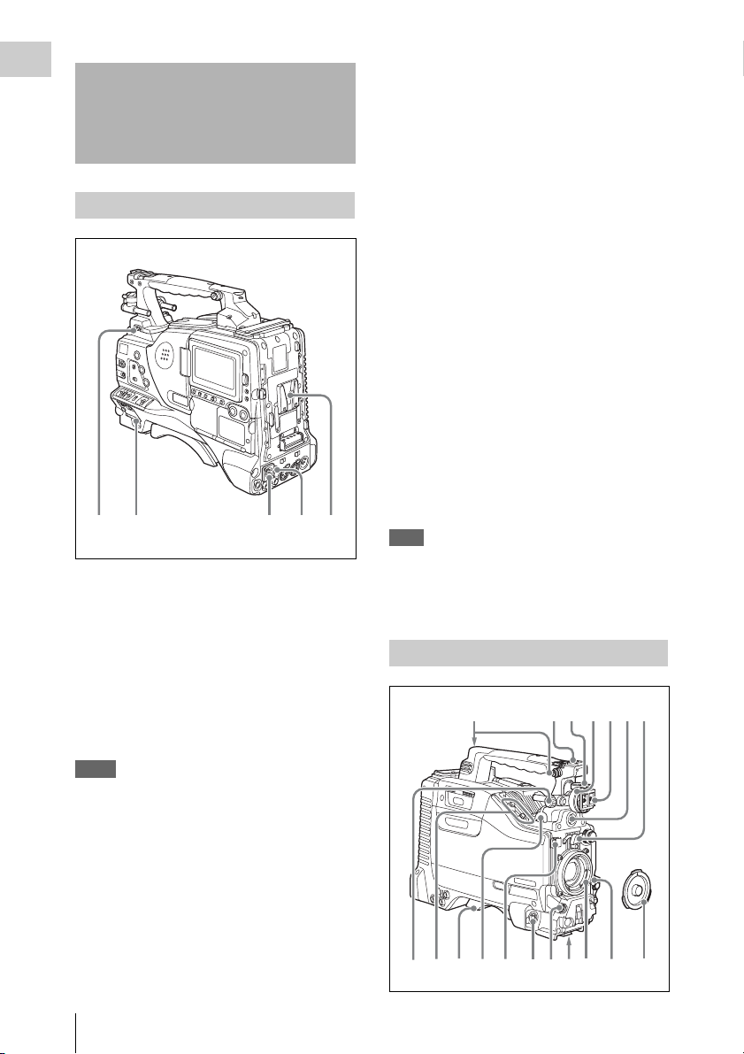
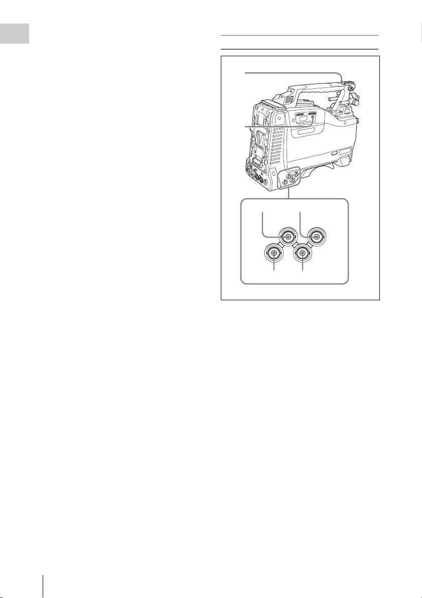
Locations and Functions of Parts and Controls
c DC IN (DC power input) connector
(XLR type, 4-pin, male)
To operate the camcorder from an AC power
supply, connect a n optional DC power cord to this
terminal and then connect the cord to the DC
output terminal of the BC-L70, BC-M150, or
another battery charger.
Power supply
a LIGHT switch
Determines how a video light connected to the
LIGHT connector (see page 11) is turned on and
off.
AUTO : When the POWER switch of the video
light is in the on position, the video light is
turned on automatically while the camcorder
is recording.
MANUAL: You can turn the video light on or off
manually, using its own switch.
Notes
• When this switch is set to AUTO, at the beginning of
the recording, the picture is recorded even though the
lighting may fluctuate until the video light comes on.
If the beginning of the recording is important, you
should set this switch to MANUAL.
• To ensure proper operation of the video light, Sony
recommends the use of the BP-GL95/L80S Battery
Pack with the camcorder.
d DC OUT 12V (DC power output)
connector (4-pin, female)
Supplies power for a WRR-860A/861/862 UHF
Synthesized Diversity Tuner (not supplied)
(maximum 0.5 A).
Do not connect any equipment other than the
UHF Synthesized Diversity Tuner.
e Battery attachment shoe
Attach a BP-GL95/GL65/L60S/L80S Battery
Pack. Alternatively, you can attach an ACDN2B/DN10 AC Adaptor to operate the
camcorder on AC power supply.
For details about how to attach the battery or AC
adaptor, see “Preparing a Power Supply” on page
29. For information about attaching a synthesized
tuner, see “Attaching a UHF portable tuner (for a
UHF wireless microphone system)” on page 39.
Note
For your safety, and to ensure proper operation of the
camcorder, Sony recommends the use of the following
battery packs: BP-GL95, BP-GL65, BP-L60S, and BPL80S.
Accessory attachments
5674231
b POWER switch
Turns the main power supply on and off.
Locations and Functions of Parts and Controls
10
90qaqs qd qgqh qj
qf8
k

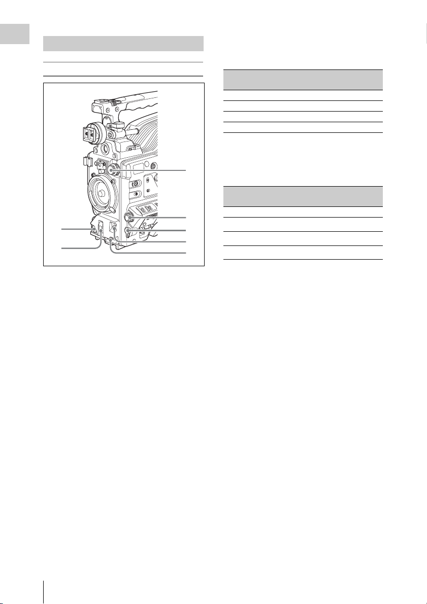
a Shoulder strap fitting
Attach the supplied shoulder strap (see page 43).
b Light fitting shoe
Attach an optional accessory such as a video light
(see page 43).
k LIGHT (video light) connector (2-pin,
female)
A video light with a maximum power
consumption of 50 W, such as the Anton Bauer
Ultralight 2 or equivalent can be connected (see
page 43).
Chapter 1 Overview
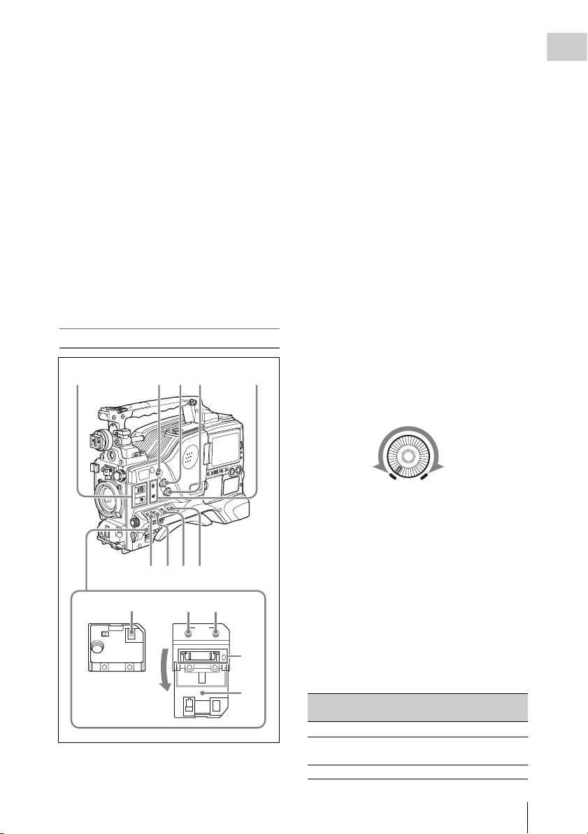
c Viewfinder front-to-back positioning
lever
To adjust the viewfinder position in the front-toback direction, loosen this lever and the LOCK
knob. After adjustment, retighten this lever and
the LOCK knob.
d Viewfinder left-to-right positioning ring
Loosen this ring to adjust the left-to-right position
of the viewfinder (see page 31).
e Viewfinder fitting shoe
Attach an optional viewfinder.
f VF (viewfinder) connector (20-pin)
Connect an optional viewfinder.
Consult a Sony representative for information about
available viewfinders.
g Lens mount securing rubber
After locking the lens in position using the lens
locking lever, fit this rubber over the lower of the
two projections. This fixes the lens mount,
preventing it from coming loose.
h Viewfinder front-to-back positioning
knob (LOCK knob)
Loosen this knob to adjust the front-to-back
position of the viewfinder (see page 31).
i Fitting for optional microphone holder
Fit an optional CAC-12 Microphone Holder (see
page 37).
l Lens cable clamp
Clamp a lens cable.
m MIC IN (microphone input) (+48 V)
connector (XLR type, 5-pin, female)
Connect a stereo microphone to this connector.
The power (+48 V) is supplied via this connector.
n LENS connector (12-pin)
Connect a lens cable to this connector.
Note
Power off this unit before connecting or disconnecting a
lens cable to this connector.
Consult a Sony representative for information about
available lenses.
o Tripod mount
When using the unit on a tripod, attach the tripod
adaptor (optional).
p Lens mount (special bayonet mount)
Attach the lens.
Consult a Sony representative for information about
available lenses.
q Lens locking lever
After inserting the lens in the lens mount, rotate
the lens mount ring with this lever to lock the lens
in position.
After locking the lens, be sure to use the lens
mount securing rubber to prevent the lens from
becoming detached.
j Shoulder pad
Raise the shoulder pad fixing lever to adjust the
position in the front-to-rear direction. Adjust the
position for maximum convenience when
operating the unit on your shoulder.
For details of the adjustment, see “Adjusting the
Shoulder Pad Position” on page 44.
r Lens mount cap
Remove by pushing up the lens locking lever.
When no lens is mounted, keep this cap fitted for
protection from dust.
Locations and Functions of Parts and Controls
11
Operating and connectors section
Chapter 1 Overview
Front
1
2
a REC START (recording start) button
Press to start recording. Press it again to stop
recording. The effect is the same as that of the
REC button on the lens.
b SHUTTER selector
Set to ON to use the electronic shutter. Flick to
SELECT to switch the shutter speed or shutter
mode setting within the range previously set with
the menu. When this switch is operated, the new
setting appears on the setting change/adjustment
progress message display area for about three
seconds.
For details about the shutter speed and shutter mode
settings, see “Setting the Electronic Shutter” on
page 50.
c FILTER selector
Selects from the filters built into this unit.
3
4
5
6
7
FILTER selector (outer knob) setting and
Electrical CC (color conversion) filter
selection
FILTER selector
(outer knob) setting
A Cross filter
B 3200K
C 4300K
D 6300K
a) A type of special effect filter that creates a cross of
light in the highlight section.
CC filter selection
a)
FILTER selector (inner knob) setting and ND
filter selection
FILTER selector
(inner knob) setting
1 Clear
2
3
4
ND filter selection
1
/4 ND
1
/16 ND
1
/64 ND
When this selector is used with the menu item for
filter selection display set to ON (see page 129),
the new setting appears on the viewfinder screen
for about three seconds.
For details, see “Adjusting the white balance” on
page 48.
d MENU knob
Changes the page selection or a setting within the
menu.
For details about how to use the MENU knob, see
“Menu Operations” on page 117.
e EARPHONE jack (monaural,
minijack)
You can monitor the E-E
1)
sound during
recording and playback sound during playback.
When an alarm is indicated, you can hear the
alarm sound through the earphone. You can use
this with the EARPHONE jack on the rear of the
unit at the same time. Plugging an earphone into
the jack automatically cuts off the built-in
speaker.
1) E-E: Abbreviation of “Electric-to-Electric”. In E-E
mode, video and audio signals input to the camcorder
are output after passing through internal electric
circuits only. This can be used to check input signals.
Locations and Functions of Parts and Controls
12
f AUTO W/B BAL (automatic white/
black balance adjustment) switch
Activates the automatic white/black balance
adjustment functions.
WHITE: Adjusts the white balance
automatically. If the WHITE BAL switch
(see page 14) is set to A or B, the white
balance setting is stored in the corresponding
memory. If the WHITE BAL switch is set to
PRST, the automatic white balance
adjustment function does not operate.
BLACK: Adjusts the black set and black balance
automatically.
g MIC (microphone) LEVEL control
Adjusts the input level of audio channels 1, 2, 3
and 4.
For details, see “Adjusting the Audio Level” on page
55.
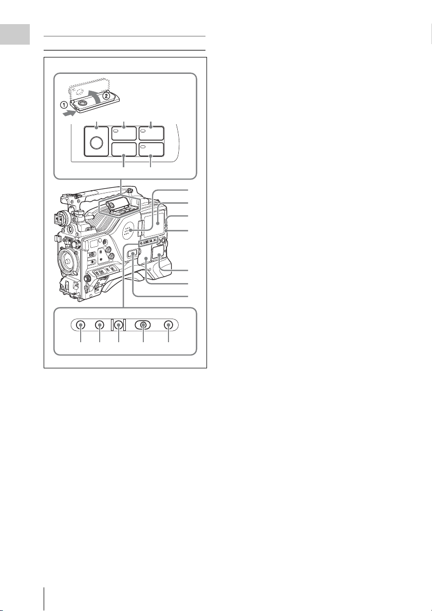
a ASSIGN (assignable) 1/2 switches
You can assign the desired functions to these
switches on the ASSIGNABLE SW page of the
OPERATION menu.
Nothing is assigned to these switches when the
camcorder is shipped from the factory (OFF is
selected in the menu).
For details, see “Assigning functions to ASSIGN
switches” on page 136.
b ASSIGN (assignable) 5 switch
You can assign the desired function to this switch
on the ASSIGNABLE SW page of the
OPERATION menu. The switch lights when
being pressed. Nothing is assigned to the switch
when the camcorder is shipped from the factory
(OFF is selected in the menu).
For details, see “Assigning functions to ASSIGN
switches” on page 136.
Chapter 1 Overview
Right side (near the front)
2341
6789
qa qs0
STATUS
ON/
SEL
OFF
OFF
MENU
CANCEL/PRST
ESCAPEON
qd
qf
5
c ALARM (alarm tone volume
adjustment) knob
Controls the volume of the warning tone that is
output via the built-in speaker or optional
earphones. When the knob is turned to the
minimum position, no sound can be heard.
ALARM
Minimum Maximum
d MONITOR (monitor volume
adjustment) knob
Controls the volume of the sound other than the
warning tone that is output via the built-in speaker
or optional earphones. When the knob is turned to
the minimum position, no sound can be heard.
e MONITOR (audio monitor selection)
switches
By means of combinations of the two switches,
you can select audio that you want to hear through
the built-in speaker or optional earphones.
Position of down-side switch: CH-1/2
Position of up-side
Audio outp ut
switch
CH-1/CH-3 Channel 1 audio
MIX Channels 1 and 2 mixed
audio (stereo)
CH-2/CH-4 Channel 2 audio
Locations and Functions of Parts and Controls
13

Position of down-side switch: CH-3/4
Chapter 1 Overview
Position of up-side
switch
CH-1/CH-3 Channel 3 audio
MIX Channels 3 and 4 mixed
CH-2/CH-4 Channel 4 audio
Audio output
audio (stereo)
By connecting stereo headphones to the
EARPHONE jack on the rear of the unit, you can
hear the audio in stereo. (On the AUDIO 1 page
of the MAINTENANCE menu, HEADPHONE
OUT must be set to STREO.)
f VTR SAVE/STBY (standby) switch
Controls the VTR power mode during pauses in
recording.
SAVE: Power saving mode. When you press the
REC START button, there is a short delay
before recording starts, but power
consumption in this mode is less than in
standby mode. As a result, battery life is
extended. When the switch is set to SAVE,
the VTR SAVE indicator in the viewfinder
lights.
STBY: Standby mode. Recording starts as soon
as you press the REC START button.
Notes
• Avoid allowing the camcorder to remain in STBY
(standby) mode for a long time.
• Even if the switch is set to the STBY position, the
camcorder can automatically turn to power saving
mode if the tape does not run for a certain period. In
such a case, the VTR SAVE indicator in the viewfinder
lights. This function is effective when a setting other
than OFF is selected for the STBY OFF TIMER on the
CAM CONFIG 1 page of the MAINTENANCE menu.
The STBY OFF TIMER item also allows you to select
the length of time until the camcorder turns to power
saving mode.
For detailed information, see “Settin g the Rec-Pause
Stand-by Off Timer” on page 80.
g GAIN selector
Switches the gain of the video amplifier to match
the lighting conditi ons during shooting. The gains
corresponding to the L, M, and H settings can be
selected in the menu. (The factory settings are
L=0 dB, M=6 dB, and H=12 dB.)
When this switch is adjusted, the new setting
appears on the setting change/adjustment
progress message display area of the viewfinder
screen for about three seconds.
For details, see “Setting gain values for the GAIN
selector positions” on page 135.
h OUTPUT/DCC (output signal/dynamic
contrast control) switch
Switches the video signal, which is output to the
VTR, viewfinder, and video monitor from the
camera section, between the following two.
BARS: Outputs the color bar signal.
CAM: Outputs the video signal from the camera.
When this is selected, you can switch DCC
1)
on and off.
1) DCC (Dynamic Contrast Control): Against a very
bright background with the iris opening adjusted to the
subject, objects in the background will be lost in the
glare. The DCC function will suppress the high
intensity and restore much of the lost detail and is
particularly effective in the following cases.
• Shooting people in the shade on a sunny day
• Shooting a subject indoors, against a background
through a window
• Any high contrast scene
i WHITE BAL (white balance memory)
switch
Controls adjustment of the white balance.
PRST: Adjusts the color temperature to the preset
value (the factory default setting: 3200K).
Use this setting when you have no time to
adjust the white balance.
A or B: Recall the white balance adjustment
settings already stored in A or B. Flick the
AUTO W/B BAL switch (see page 13) on th e
WHITE side, to automatically adjust the
white balance, and save the adjustment
settings in memory A or memory B.
You can use the AUTO W/B BAL switch
even when ATW
1)
is in use.
B (ATW): When this switch is set to B and
WHITE SWITCH <B> is set to ATW on the
WHITE SETTING page of the
OPERATION menu, ATW is activated.
When this switch is adjusted, the new setting
appears on the setting change/adjustment
progress message display area of the viewfinder
screen for about three seconds.
1) ATW (Auto Tracing White Balance): The white
balance of the picture being shot is adjusted
automatically for varying lighting conditions.
j STATUS ON/SEL/OFF (menu display
on/page selection/display off) switch
This switch is enabled when the menu is not
displayed.
Locations and Functions of Parts and Controls
14

ON/SEL: Each time this switch is pushed
upward, a window to confirm the menu
settings and status of the camcorder appears
on the viewfinder screen. The window
consists of four pages, which are switched
each time the switch is pushed upward. Each
page is displayed for about 10 seconds.
OFF: To clear the page after display, push this
switch down to the OFF position.
You can select the pages to be displayed on the
menu.
For details, see “Displaying the status confirmation
screens” on page 134.
k MENU ON/OFF switch
To use this switch, open the cover.
This switch is used to display the menu on the
viewfinder screen or the test signal screen.
Closing the cover automatically sets this switch to
OFF.
ON: Displays the menu on the viewfinder screen
or the test signal screen.
OFF: Removes the menu from the viewfinder
screen or the test signal screen.
For details, see “Menu Operations” (page 117).
l CANCEL/PRST (preset)/ESCAPE
switch
To enable this switch, set the MENU ON/OFF
switch to ON.
Closing the cover automatically sets the MENU
ON/OFF switch to OFF.
CANCEL/PRST: Flicking this switch up to this
position displays the message to confirm
whether the previous sett ings are cancelled or
settings are reset to their initial values,
depending on the menu operating condition.
Flicking this switch up to this position again
cancels the previous settings or resets the
settings to their initial values.
ESCAPE: Use this switch when the menu page,
which has a hierarchical structure, is opened.
Each time the switch is flicked to this
position, the page returns to one stage higher
in the hierarchy.
m “Memory Stick” compartment
Chapter 1 Overview
Label
“Memory Stick” Access indicator
Open the lid of the menu operating section, and
insert a “Memory Stick”, with the notch facing
downward, in the direction shown by the arrow,
so that it clicks into place.
To remove a “Memory Stick”, first press it in to
release the lock, then withdraw.
The “Memory Stick” access indicator lights in
green when a “Memory Stick” is loaded, and
lights in red when the “Memory Stick” is being
accessed for reading or writing.
For details about “Memory Stick”, see “Handling
the “Memory Stick”” on page 142.
n Cover
Locations and Functions of Parts and Controls
15
Right side (near the rear)
Chapter 1 Overview
c WARNING indicator
Lights up or flashes when an abnormality occurs
in the VTR section.
For details about the meaning of the states of the
WARNING indicator, see ““Operation Warnings”
on page 159.
89q;
REW
EJECT
Z
F FWD
m
M
PLAYSTOP
x
N
qa qs
1
2
3
4
5
6
7
BRIGHTDISPLAYRESETHOLDDISP SEL
CTL TC DATA
qd qf qg qh qj
a Built-in speaker
The speaker can be used to monitor E-E sound
during recording, and playback sound during
playback. The speaker also sounds alarms to
reinforce visual warnings.
If you connect earphones to the EARPHONE
jack, the speaker output is suppressed
automatically.
For details about alarms, se e “Operation Warnings”
on page 159.
d TAPE indicator
This lights when a cassette is loaded.
e Protection cover of the audio control/
timecode operations sections
Open to access the audio control section and the
timecode operation section.
For details, see “Timecode/menu operations
section and audio control section” on page 21
.
f Protection cover of the timecode/menu
operations section
Open to access the buttons and switches used for
setting timecode and user bit values and
performing menu operations.
For details, see “Timecode/menu operations
section and audio control section” on page 21
.
g Monochrome LCD
This shows the remaining battery capacity,
remaining tape recording time, time data, and so
on.
For details, see “Status displays on the LCD monito r
and monochrome LCD” on page 18.
h EJECT button
Press this button to eject or load a cassette.
i REW (rewind) button and indicator
Press this button to rewind the tape. The indicator
lights during rewinding.
j F FWD (fast forward) button and
indicator
Press this button to fast forward the tape. The
indicator lights during fast forward.
b LCD monitor
Displays camera video, VTR-related warnings,
remaining battery capacity, remaining tape
recording time, audio levels, time data, and so on.
For details, s ee “Status displays on th e LCD monitor
and monochrome LCD” on page 18.
Locations and Functions of Parts and Controls
16
k STOP button
Press this button to stop the tape.
l PLAY button and indicator
Press this button to view the recorded picture in
the viewfinder or on the color video monitor. The
indicator lights during playback. The four times
normal speed search function is provided to make

it far quicker to find a desired location of the tape.
Press the REW button or F FWD button during
playback to view the four times normal speed
search picture.
m DISP SEL (display selection) button
With each press of this button, the display in the
LCD monitor changes as follows.
Display indication Meaning
Video with
superimposed
information (CHAR)
Video without
superimposed
information (MONI)
Status display
(STATUS)
The LCD monitor displays
the same text information
as the viewfinder.
The video only appears.
Counter indications,
warnings, audio levels, and
similar information appear.
No video image appears.
n HOLD (display hold) button
Pressing this button instantly freezes the time data
displayed in the counter display section. (The
timecode generator continues running.) Pressing
this button again releases the hold.
You can use this button, for example, to
determine the exact time of a particular shot.
For details of the counter display, see page 18.
o RESET button
Resets the value shown in the time counter
display. According to the settings of the PRESET/
REGEN/CLOCK switch (see page 21), the FRUN/SET/R-RUN switch (see page 21), and the
DATA DISPLAY switch (see page 21), this
button resets the display as follows.
Settings of switches To re set
DISPLAY switch:
CTL
DISPLAY switch:
TC
PRESET/REGEN/
CLOCK switch:
PRESET
F-RUN/SET/R-RUN
switch: SET
DISPLAY switch:
DATA
PRESET/REGEN/
CLOCK switch:
PRESET
F-RUN/SET/R-RUN
switch: SET
DATA DISPLAY
switch: U-BIT
a) Of the timecode bits for every frame recorded on the
tape, those bits which can be used to record useful
information for the user such as scene number,
shooting place, etc.
For details, see “Setting the Time Data” on page 58.
CTL to 0:00:00:00
Timecode to 00:00:00:00
User bits data
00
a)
to 00 00 00
p DISPLAY switch
CTL: Displays control signal.
TC: Displays timecode.
DATA: Displays the item selected with the
DATA DISPLAY switch.
For details, see “Status displays on the LCD monito r
and monochrome LCD” on page 18.
q BRIGHT (brightness) button
Switches the brightness of the LCD monitor
backlight, and turns the backlight of the
monochrome LCD on and off.
Each press of the button selects the next setting in
the order shown in the following table.
Chapter 1 Overview
Locations and Functions of Parts and Controls
17
Setting LCD monitor
Chapter 1 Overview
backlight
H High (select this to view
Monochrome
LCD backlight
Lit
the LCD monitor
outdoors in the
daytime)
M Brightness between H
Lit
and L
L Low (select this to view
Lit
the LCD monitor
indoors or outdoors at
night)
OFF Off (the display is also
Off
off)
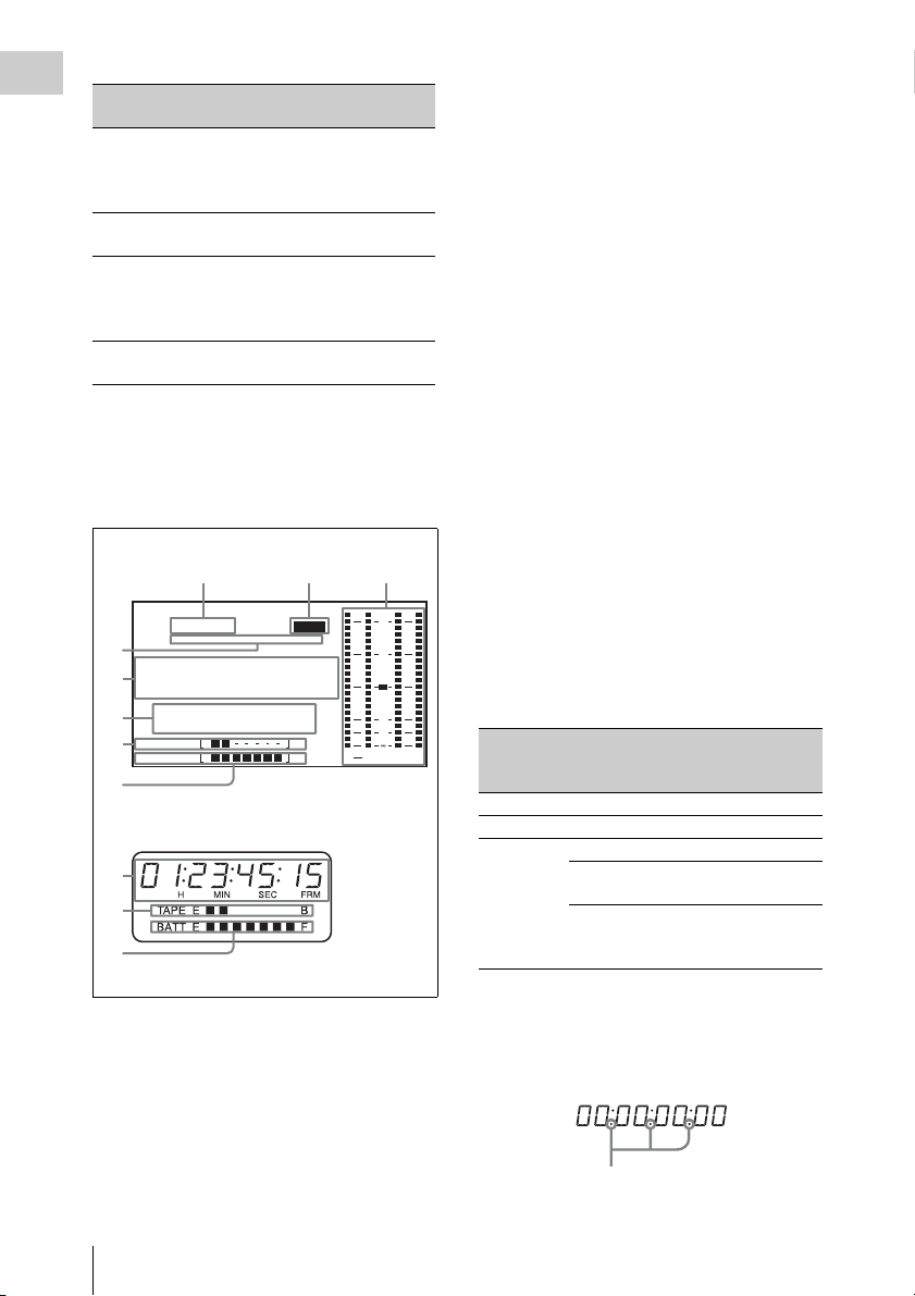
Status displays on the LCD monitor and
monochrome LCD
The following displays appear on the LCD
monitor and monochrome LCD when STATUS is
selected with the DISP SEL button.
123
59.94i
4
5
6
7
8
PB NDF EXT-LK21HOLD
.....
01
23 45 15
H
RF1 RF2 SERVO
HUMID SLACK
TAPE E B
BATT EF
MIN SEC FRM
LCD monitor
EMPH
.
5
7
8
Monochrome LCD
a Frame frequency
Indicates the currently selected frame frequency.
59.94i: 59.94 fields per second, interlace scan
mode
50i: 50 fields per second, interlace scan mode
25PsF: 25 frames per second, progressive scan
mode (HDW-650P only)
23.98PsF: 23.98 frames per second,
progressive scan mode (HDW-650F only)
b Emphasis display
Lights during recording or playback when
emphasis processing is performed on audio
signals.
c Audio level indicators
Indicates the audio recording or playback levels
of channels 1 to 4.
d Status display
PB: Appears when the tape is running.
NDF: Appears when non-drop-frame timecode is
selected.
EXT-LK: Appears when the internal timecode
generator is locked to an external signal input
to the TC IN (timecode input) connector.
HOLD: Appears when the internal timecode
generator is stopped.
e Time counter display
Displays timecode, CTL signals, user bits or the
real time. Except when the timecode is being set,
the information displayed is determined by the
settings of the DISPLAY and DATA DISPLAY
OVER
0
10
20
30
40
dB
ST
PEAK
switches.
For more information about timecode, see “Setting
the timecode” (page 58).
Switch settings related to timecode and
displayed information
43
DISPLAY
switch
position
DATA
DISPLAY
switch position
Displayed
information
CTL Any position Control signal
TC Any position Timecode
DATA U -BIT User bits
SHOT TIME Data and time
from shot data
SHOT-NO Time counter is
not used (currently
zero is displayed)
When the HOLD button is pressed to hold the
timecode value, the timecode is displayed in the
format shown below. When the HOLD button is
pressed again to release the hold, the timecode is
displayed in the normal format.
Lights when the HOLD button is pressed.
Locations and Functions of Parts and Controls
18

f Warning indicator area
Displays warnings when trouble with recording
or moisture condensation occurs.
For details, see “Operation Warnings” on page 159.
Chapter 1 Overview
Locations and Functions of Parts and Controls
19

g Remaining tape recording time indicator
Chapter 1 Overview
Indication Remaining recording time
TAPE E [ x x x x x x x] B More than 30 minutes
TAPE E [ x x x x x x x] B 25 to 30 minutes
TAPE E [ x x x x x x x] B 20 to 25 minutes
TAPE E [ x x x x x x x] B 15 to 20 minutes
TAPE E [ x x x x x x x] B 10 to 15 minutes
TAPE E [ x x x x x x x] B 5 to 10 minutes
TAPE E [ x x x x x
TAPE E [ x x x x x x x] B (flashing)
x x] B 2 to 5 minutes
a)
0 to 2 minutes
TAPE E [ x x x x x x x] B (flashing) 0 minutes
a) During recording
h Remaining battery capacity indicator
Indication Battery voltage
BP-L90A/L60S/L80S
Other batteries
BATT E [ x x x x x x x] F 15.5 V or more 17.0 V or more
BATT E [ x x x x x x x] F 15.1 to 15.5 V 16.0 to 17.0 V
BATT E [ x x x x x x x] F 14.6 to 15.1 V 15.0 to 16.0 V
BATT E [ x x x x x x x] F 13.8 to 14.6 V 14.0 to 15.0 V
BATT E [ x x x x x x x] F 12.9 to 13.8 V 13.0 to 14.0 V
BATT E [ x x x x x x x] F 12.0 to 12.9 V 12.0 to 13.0 V
BATT E [ x x x x x
x x] F 10.8 to 12.0 V 11.0 to 12.0 V
BATT E [ x x x x x x x] F 10.8 V or less 11.0 V or less
a) You can change the threshold voltages on the
BATTERY 2 page of the MAINTENANCE menu
(see page 102).
Indication Battery voltage
BP-GL95/GL65/IL75/M100, Anton Bauer Battery
System
BATT E [ x x x x x x x] F 80 to 100%
BATT E [ x x x x x x x] 70%
BATT E [ x x x x x x x] 60%
BATT E [ x x x x x x x ] 50%
BATT E [ x x x x x x x] 40%
BATT E [ x x x x x x x] 30%
BATT E [ x x x x
x x x] 20%
BATT E [ x x x x x x x] 10%
BATT E [ x x x x x x x]0%
a)
Locations and Functions of Parts and Controls
20

Timecode/menu operations section and audio
67890
control section
1234 5
LEVEL
CANCEL/PRST
U-BIT
SHOT
MENU
DATA DISPLAY
ENTER
CUE IN
CH-1
TIME
MIX
NO
CH-2
010010
F-RUN
SET
R-RUN
CH-1
PRESET
REGEN
CLOCK
AUTO
MANUAL
AUDIO SELECT
AUDIO IN
FRONT
REAR
WIRELESS
CH-3
F
R
W
CH-2
CH-4
F
R
W
a MENU button
When pressed, enables menu operations with the
arrow keys, the CANCEL/PRST button, and the
ENTER button.
The menu appears temporarily, even when the
MENU ON/OFF switch is in the OFF position.
For details, see “Menu Operations” (page 117).
F-RUN: Timecode keeps advancing, regardless
of the operating state of the VTR. Use this
setting when synchronizing the timecode
with an external timecode.
SET: Sets the timecode or user bits.
R-RUN: Timecode advances only during
recording. Use this setting to have a
consecutive timecode on the tape.
For details, see “Setting the timecode” on page 58
and “Setting the user bits” on page 58.
e AUDIO LEVEL CH-1/CH-2 (audio
channel 1/2 recording level) knobs
Adjusts the audio levels to be recorded on
channels 1 and 2 when the AUDIO SELECT CH1/CH-2 switches (see page 22) are set to
MANUAL.
f DATA DISPLAY switch
U-BIT: Displays the user bit value.
SHOT TIME: Displays the date and time from
the shot data.
SHOT-NO: Time counter is not used.
Chapter 1 Overview
b ENTER button and arrow buttons
Use to set timecode and user bit values, and for
menu screen operations.
Select items and change their values with the
arrow buttons, and confirm with the ENTER
button for menu screen operations.
When setting timecode and user bits, use the right
and left arrow buttons to select the digit to modify
(the selected digit flashes), and use the up and
down arrow buttons to increment and decrement
the flashing digit.
c CANCEL/PRST (menu cancel/preset)
button
This button is also enabled when the MENU
button is pressed to enable arrow key operations.
Cancels changes to a menu setting, or resets one
or more settings to the default settings. A message
appears so that you can confirm the cancellation
or reset. Press again to confirm the cancellation or
reset.
d F-RUN/SET/R-RUN (free run/set/
recording run) switch
Selects the operating mode of the internal
timecode generator. The operating mode is set as
explained below, depending on the position of the
switch.
g CUE IN(cue track input) switch
Selects the input signal to be recorded on the cue
track.
CH-1: Signal selected by the AUDIO IN CH-1
switch
MIX: Mixed signals selected by the AUDIO IN
CH-1 and CH-2 switches
CH-2: Signal selected by the AUDIO IN CH-2
switch
Note
When recording mixed signals by setting this switch to
MIX, be sure to confirm that the emphasis settings of the
two channels (on/off) are the same. If they are different,
the camcorder cannot record or play back mixed signals
correctly.
When the AES/EBU format audio signal is selected, the
emphasis settings are determined by the channel status of
the AES/EBU format audio signal (emphasis bit).
When an audio signal other than the AES/EBU format
audio signal is selected, the emphasis setting depends on
the setting of AU REC EMPHASIS (see page 103) on
the AUDIO 2 page of the MAINTENANCE menu.
Use this in combination with other buttons.
h PRESET/REGEN (regeneration)/
CLOCK switch
Selects whether to set a new timecode or to utilize
the existing timecode.
PRESET: Records a new timecode.
Locations and Functions of Parts and Controls
21
REGEN: Records timecode continuous with the
Chapter 1 Overview
existing timecode recorded on the tape.
Regardless of the setting of the F-RUN/SET/
R-RUN switch, the camcorder operates in RRUN mode.
CLOCK: Records timecode synchronized to the
internal clock. Regardless of the setting of
the F-RUN/SET/R-RUN switch, the
camcorder operates in F-RUN mode.
i AUDIO SELECT CH-1/CH-2 (audio
channel 1/2 adjustment method
selection) switches
Select the audio level adjustment method for each
of audio channels 1 and 2.
AUTO : Automatic adjustment
MANUAL: Manual adjustment
j AUDIO IN CH-1/CH-2/CH-3/CH-4
(audio channel 1/2/3/4 input selection)
switches
AUDIO IN CH-1/CH-2 switches
Select the audio input signals to be recorded on
audio channels 1 and 2.
FRONT: Audio input signals from the
microphone connected to the MIC IN
connector
REAR: Audio input signals from an audio device
connected to the AUDIO IN CH-1/CH-2
connectors
WIRELESS: Audio input signals from the UHF
portable tuner (supplied separately) if it is
installed
AUDIO IN CH-3/CH-4 switches
Select the audio input signals to be recorded on
audio channels 3 and 4.
F (FRONT): Audio input signals from a
microphone connected to the MIC IN
connector
R (REAR): Audio input signals from an audio
device connected to the AUDIO IN CH-1/
CH-2 connectors
W (WIRELESS): Audio input signals from the
UHF portable tuner (supplied separately) if it
is installed
Left side and upper section
1
2
34
GEN LOCK
IN
TEST
OUT
TC OUT
56
a ASSIGNABLE 3/4 switches
You can assign the desired functions to these
switches on the ASSIGNABLE SW page of the
OPERATION menu.
Nothing is assigned to these switches when the
camcorder is shippe d from the factory (equivalent
to a selection of OFF in the menu).
For details, see “Assigning functions to ASSIGN
switches” on page 136.
b Lid of the cassette compartment
This opens when the EJECT button on the top
panel is pressed. Press the side of the lid to close.
c GEN LOCK IN (genlock signal input)
connector (BNC type)
• This connector inputs a reference signal when
the camera is to be genlocked or when timecode
is to be synchronized with external equipment.
Use the GENLOCK page of the
MAINTENANCE menu to adjust the genlock
H-phase (phase of horizontal sync signal).
• This connector also inputs a return video signal.
The HD-Y signal can be displayed in the
viewfinder screen wh ile holding the RET button
TC IN
Locations and Functions of Parts and Controls
22
down with RETURN VIDEO set to ON on the
ASSIGNABLE SW page of the OPERATION
menu.
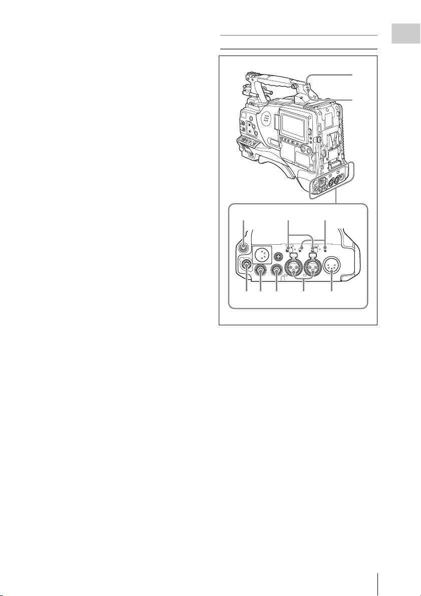
Rear
Chapter 1 Overview
d TC IN (timecode input) connector
(BNC type)
To apply an external lock to the timecode of this
unit, input the reference timecode.
For details of timecode, see “Setting the timecode”
on page 58.
e TEST OUT connector (BNC type)
This connector outputs the video signal for a
video monitor. The output signal can be selected
from composite video, HD-Y, R, G, and B. To
switch output signals, use the TEST OUT
SELECT item on the OUTPUT 1 page of the
OPERATION menu.
If the output signal is set to one of R, G, or B, then
this setting changes to HD-Y when the camcorder
is powered off and on again.
Depending on menu settings, menus, timecode,
and shot data can be superimposed on the image
on the monitor. This connector can also be used to
synchronize the timecode of an external VTR
with the timecode of the camcorder.
f TC OUT (timecode output) connector
(BNC type)
To lock the timecode of an external VTR to the
timecode of this unit, connect this connector to
the external VTR’s timecode input connector.
1
2
345
AUDIO IN
AES/EBU
AES/EBU
LINE MIC
LINE MIC
DC OUT
12V
HDSDI OUT
HD/SD SDI OUT
0.5A
CH1
1/2
DC
IN
48V
48V
OFF
OFF
AUDIO OUT
CH2
3/4
67 8 9 0
a TALLY (back tally) indicator (red)
Lights up during recording. It will not light if the
TALLY switch is set to OFF. This indicator also
flashes to indicate warnings (see page 16) in the
same manner as the REC/TALLY indicator in the
viewfinder.
For details, see “Operation Warnings” on page 159.
b TALLY switch
Set to ON to activate the TALLY indicator
function.
c EARPHONE jack (stereo, minijack)
You can monitor the E-E sound during recording
and playback sound during playback. When an
alarm is indicated, you can hear the alarm sound
through the earphone. You can use this with the
EARPHONE jack on the front of the unit at the
same time. Plugging an earphone into the jack
automatically cuts off the built-in speaker.
You can select monaural or stereo on the
AUDIO 1 page of the MAINTENANCE menu.
Locations and Functions of Parts and Controls
23
d LINE /AES/EBU / MIC selectors
q
These select the audio source of the audio input
Chapter 1 Overview
signals input to the AUDIO IN CH1/CH2
connectors.
LINE: Line input audio equipment
AES/EBU: AES/EBU format audio signal
MIC: Microphone input
Note
When either of these selectors is in the MIC position, and
the corresponding +48V/OFF switch is in the +48V
position, and you inadvertently connect any audio device
other than a microphone to the corresponding connector
(AUDIO IN CH1 or CH2), the connected device may be
damaged.
e +48V/OFF switches
Select either of the following positions for the
microphones to be connected.
+48V: For a microphone that uses an external
power supply
OFF: For a microphone that uses an internal
power supply
f REMOTE connector (8-pin)
Connect an RM-B150/B750 Remote Control
Unit, which makes it possible to control the
camcorder remotely.
Note
Before connecting/disconnecting the Remote Control
Unit to/from the camcorder, be sure to turn off the
camcorder POWER switch.
g HDSDI OUT connector (BNC type)
Outputs an HDSDI signal (with embedded
audio).
h HD/SD SDI OUT connector (BNC type)
Outputs an HDSDI or SDSDI signal (with
embedded audio). To switch between HDSDI and
SDSDI output, use the HD/SD SDI OUT item on
the OUTPUT 1 page of the OPERATION menu.
Setting menus, timecode, or shot data can be
superimposed on the camera output video
depending on the menu settings, and you can
view them on the monitor screen.
i AUDIO IN CH1/CH2 (audio channel-1
and channel-2 input) connectors (XLR
type, 3-pin, female)
These are audio input connectors for channels 1
and 2 to which you can connect audio equipment
or a microphone.
When the LINE / AES/EBU / MIC selectors are
set to LINE or MIC, the CH1 connector is used
for channel-1 and -3 inputs, and the CH2
connector for channel-2 and -4 inputs.
When the LINE / AES/EBU / MIC selectors are
set to AES/EBU, the CH1 connector is used for
channel-1 and -2 inputs, and the CH2 connector,
for channel-3 and -4 inputs.
j AUDIO OUT connector (XLR type, 5-
pin, male)
Outputs the audio signals recorded on audio
channels 1 and 2 or audio channels 3 and 4. The
audio signals are selected by the MONITOR
switches.
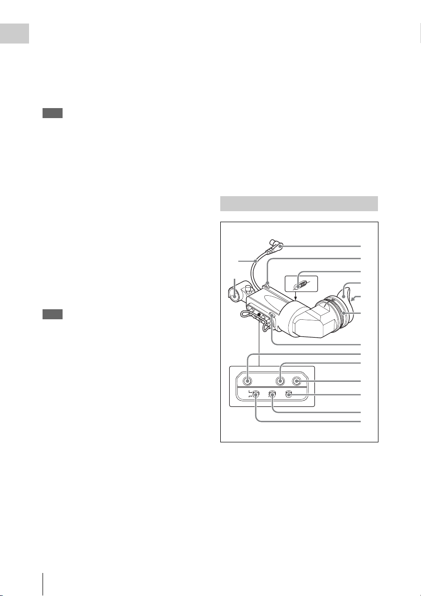
HDVF-20A viewfinder (optional)
1
qf
qg
PEAKING CONTRAST BRIGHT
DISPLAY
ASPECT
TALLY
ZEBRA
HIGH
ON
OFF
OFF
LOW
MOMENT
a Plug
Connect to the VF connector on the camcorder.
b Stopper
Prevents the viewfinder from coming off the
camcorder when it is slid from side to side.
c Camera operator tally indicator
Lights up while camcorder is recording. This
indicator can be covered when not in use.
2
3
4
5
6
7
8
9
0
qa
qs
d
Locations and Functions of Parts and Controls
24
This indicator also flashes to indicate warnings, in
6
the same manner as the tally indicator and the
REC indicator in the viewfinder.
d Eyecup
e Indicators and status display
For details, see “Status display on the viewfinder
screen” on page 25.
f Diopter adjustment ring
Allows for optimal focus adjustment.
g Tally indicator
Lights up while camcorder is recording. Set the
TALLY switch to OFF when not in use. The
brightness can also be adjusted with the TALLY
switch.
This indicator also flashes to indicate warnings, in
the same manner as the camera operator tally
indicator and the REC indicator in the viewfinder.
h PEAKING control
Turning this control clockwise adjusts the picture
sharpness, and makes focusing easier. This
control has no effect on the output signals of the
camcorder.
i CONTRAST control
Adjusts the contrast of the screen. This control
has no effect on the output signals of the
camcorder.
j BRIGHT control
Adjusts the brightness of the screen. This control
has no effect on the output signals of the
camcorder.
m DISPLAY/ASPECT switch
Turns the marker indication on and off, and
switches between 4:3 and 16:9 aspect ratios for
viewfinder screen display.
DISPLAY: When the marker indication is
enabled with the camcorder, the marker
indication on the viewfinder screen turns on
and off every time you push the switch up to
this position.
ASPECT: Each push of the switch down to this
position toggles the mask display on and off.
(Make mask display settings on the
MARKER 1 page of the OPERATION menu
(see page 88).)
n Viewfinder cable
o Microphone holder
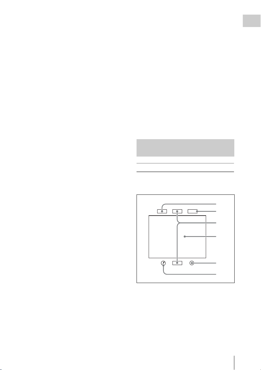
Status display on the viewfinder screen
Indicators
The following indicators are arranged above and
below the viewfinder screen to show the current
state and adjustments of the camcorder.
TALLY/REC
BATT
1
2
3
4
Chapter 1 Overview
k TALLY switch
Controls the tally indicator located on the front of
the viewfinder.
HIGH: The tally indicator brightness is set to
high.
OFF: The tally indicator is disabled.
LOW: The tally indicator brightness is set to low.
l ZEBRA (zebra pattern) switch
Controls the zebra pattern display on the
viewfinder screen as follows.
ON: A zebra pattern appears and stays.
OFF: The zebra pattern disappears.
MOMENT: A zebra pattern appears and stays for
about five seconds.
VTR
SAVE
5
a TALLY (green tally) indicator
Lights when the camcorder is in Picture Cache
mode, and flashes when it is in Auto Interval Rec
or Manual Interval Rec mode. Also, lights in
green when the HDW-250/S280 connected to the
HDSDI OUT connector starts recording, if
HDSDI REMOTE I/F on the CAM CONFIG 2
page of the MAINTENANCE menu is set to GTLY.
Locations and Functions of Parts and Controls
25
b BATT (battery) indicator
This indicator starts flashing when the battery
Chapter 1 Overview
connected to the camcorder is nearly exhausted,
and stays lit when the battery is completely
exhausted.
To prevent interruption during operation, replace
the battery as soon as this indicator starts flashing.
The battery power level at which the indicator starts
flashing can be set on the BATTERY 1 page of the
MAINTENANCE menu. For details, see page 101.
c REC (recording, red tally) indicator
Lights up while camcorder is recording.
This indicator also flashes to indicate warnings, in
the same manner as the tally indicator and the
camera operator tally indicator.
d Viewfinder screen
e VTR SAVE indicator
This indicator lights when the VTR SAVE/STBY
switch is set to SAVE, putting the VTR into
power save mode.
f ! (warning) indicator
This indicator lights when any of the following
conditions occurs with the corresponding item set
to ON on the ‘!’ LED page of the OPERATION
menu.
• The gain is set to other than 0 dB.
• The SHUTTER selector is set to ON.
• The WHITE BAL switch is set to PRST.
• The electric CC filter is ON.
• ATW is enabled.
• The lens extender is used.
• The reference value of auto iris adjustment is
not the standard value.
The conditions that cause the indicator to light
can be changed on the ‘!’ LED STD page of the
OPERATION menu.
For details, see “Selecting the conditions that light
the ‘!’ (warning) indicator” (page 129).
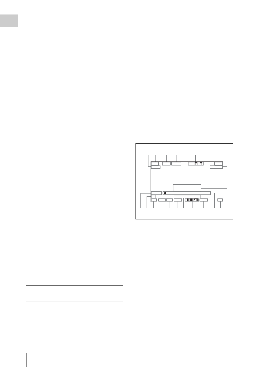
Layout of the status display on the
viewfinder screen
The viewfinder screen displays not only the video
picture but also characters and messages
indicating the camcorder settings and operating
status, a center marker, a safety zone marker, etc.
When the menu screen is not displayed and the
DISPLAY of the DISPLAY/ASPECT switch is
set to ON, the items for which an ON setting was
made on the VF DISP 1, VF DISP 2, or VF DISP
3 page of the OPERATION menu or with related
switches are displayed at the top and bottom of
the screen.
The messages that give details of the settings and
adjustment progress and results can also be made
to appear for about three seconds while settings
are being changed, during adjustment, and after
adjustment.
For details about the display item selection, see
“Selecting the display items” on page 128.
For details about setting change and adjustment
progress messages, see “Change confirmation/
adjustment progress messages” on page 129.
For details about marker display, see “Setting the
marker display” on page 131.
All items that can be displayed on the viewfinder
screen are shown below.
12 3 45 67
EX Z
MIX DC IN
AWB:NG
OVER LEVEL
REC2 TCG 00:30:11:03
5600
LOW LIGHT
1A -
0qsqdqfqg qkqjqh ql
89 qa
13.9
K+ W
99
W:A
13.4
1 2
1
2
V
F1.718 F 30dB 1/ 2000
a Playback mix
“MIX” appears when the playback mix function
is set to ON.
b Extender
Displays the extender settings of this unit and the
lens.
EX: The lens extender is on.
08: The lens shrinker is on.
x2D: This unit’s extender function is on.
Ex2D: The lens extender and the digital extender
function of this unit are both on.
c Zoom position
Indicates the zoom position of the zoom lens in
the range from 0 to 99.
Locations and Functions of Parts and Controls
26

d Color temperature
Displays a color temperature calculated from the
gain of R and B, in the range 0.0 K to 99.9 K (in
steps of 0.1 K). The +/– signs may be displayed
depending on the OFFSET WHT setting (see
page 138).
No display: OFFSET WHT is OFF
+: The value of OFFSET WHT is greater than
3200K.
–: The value of OFFSET WHT is less than
3200K.
e Wireless microphone reception level
When a UHF portable tuner is installed in the
camcorder, “W” appears together with foursegment reception level indicators for each of the
channels (1 or 2 channels) of the tuner. The
indications are as follows.
Normal use: The number of white segments
indicates the strength of the signal level.
Muted: The number of gray segments indicates
the strength of the signal level.
Reception level over peak: “P” is displayed
instead of the indicators.
1)
Tuner battery is low: The channel number and
indicator of the corresponding channel
1)
flash.
1) DWR-S01D only
f Power source voltage/battery
remaining capacity
When the unit is powered from a battery pack,
indicates the remaining capacity of the power
source voltage. When the unit is powered from a
battery connected to the DC IN connector or AC
adaptor attached to the battery attachment shoe,
indicates the power source voltage.
g External battery
Appears if the power is supplied from an AC
adaptor connected to the DC IN connector.
h External device control
Flashes when recording operation by the external
device connected to the HDSDI OUT connector
is being controlled.
However, this indicator only appears when
HDSDI REMOTE I/F on the CAM CONFIG 2
page of the MAINTENANCE menu is set to
CHARA and HD SDI OUT on the OUTPUT 1
page of the OPERATION menu is set to HDSDI.
i Electric CC (color temperature) filter
Displays the color temperature when the electric
CC filter is ON.
j Filter
Indicates the currently selected filter type (see
page 12).
k White balance memory
Indicates the currently selected white balance
automatic adjustment memory.
A: Displayed when the WHITE BAL switch is set
to A.
B: Displayed when the WHITE BAL switch is set
to B.
P: Displayed when the WHITE BAL switch is set
to PRST or when the preset button on an RMB150 has been pressed.
T: Displayed when ATW is being used.
l Gain value
Indicates the gain value (in dB) of the video
amplifier, as set by the GAIN selector.
m Shutter speed
Indicates the shutter speed or the shutter mode.
However, if the SHUTTER selector (see page 12)
is set to OFF, nothing is displayed.
For details of the displayed shutter speed, see
“Setting the Electronic Shutter” on page 50.
n Operation/alarm message display area
For details, see “Operation/alarm messages” on
page 162.
o Audio level
Indicates the level of audio channel 1 and channel
2. The peak indication of the VTR level meter is
related as follows to the audio level.
1
2
3
-40 -30 -20 -17 -14(dB)
1Audio channel 1 level indicator
2Audio channel 2 level indicator
3VTR level meter indicator
p Remaining tape recording time
Indicates the remaining recording time (in
minutes) of the tape.
Chapter 1 Overview
Locations and Functions of Parts and Controls
27

Examples of remain ing recording time indication
Chapter 1 Overview
Indication Remaining recording
F-30 All to 30 minutes
30-25 30 minutes to 25 minutes
25-20 25 minutes to 20 minutes
20-15 20 minutes to 15 minutes
15-10 15 minutes to 10 minutes
time
q Timecode
Indicates the elapsed recording/playback time,
timecode, user bits or other information selected
by the DISPLAY switch (see page 17) and the
DATA DISPLAY switch (see page 21).
r Iris setting/auto iris override
Indicates the F value (iris setting) of the lens.
Auto iris override is shown by an indicator made
up of two segments each on the upper and lower
sides.
For details, see “Changing the Reference Value for
Automatic Iris Adjustment” on page 53.
s Setting change and adjustment
progress message display area
For details, see “Change confirmation/adjustment
progress messages” on page 129.
Locations and Functions of Parts and Controls
28
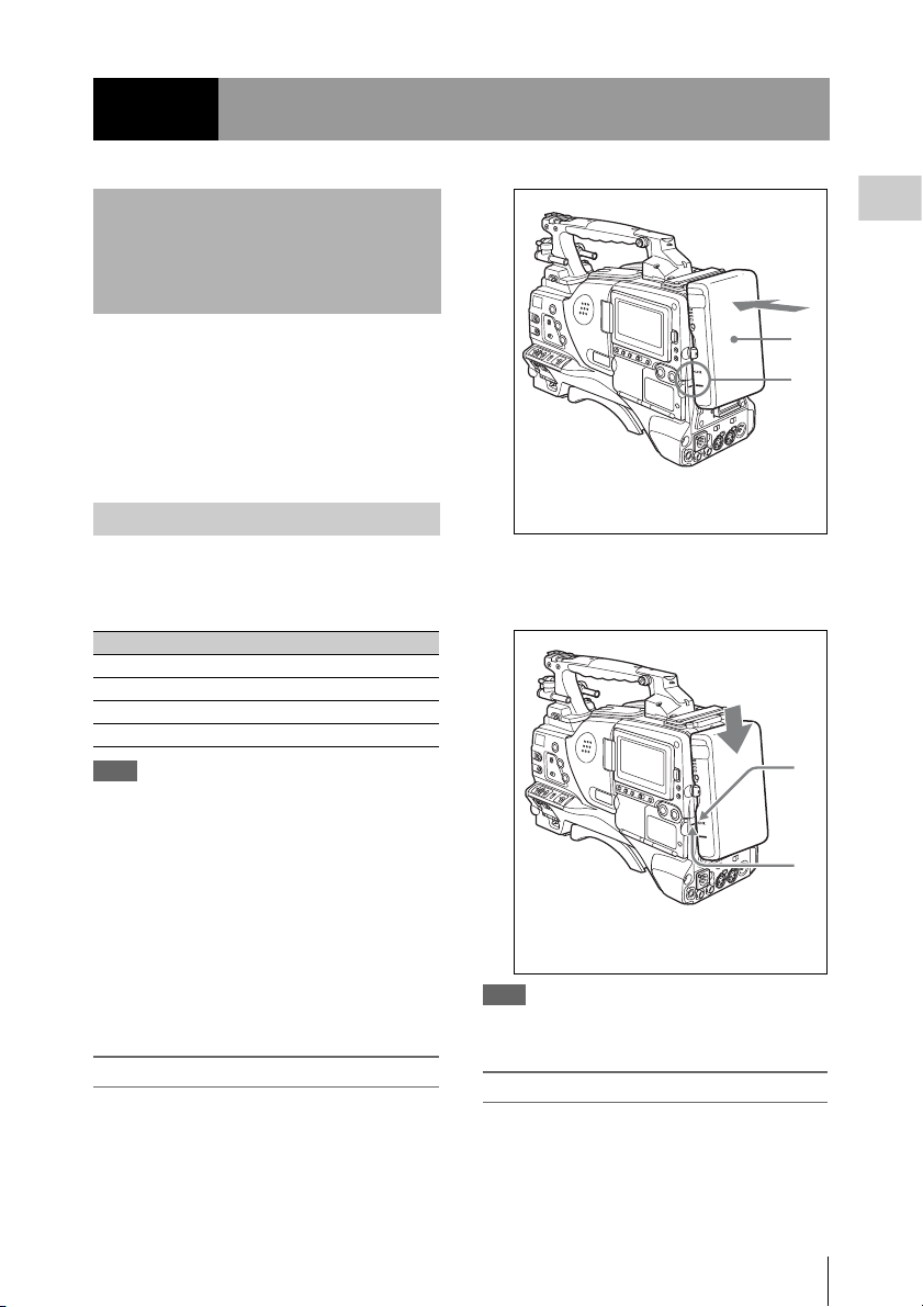
Chapter2 Preparations
Preparing a Power Supply
For safety, use only the Sony battery packs listed
below.
• BP-GL95/GL65/L60S/L80S Lithium-ion
Battery Pack
• AC power using the AC-DN2B/DN10 AC
adaptor
Using a battery pack
When a BP-GL95/GL65/L60S/L80S Battery
Pack is used, the camcorder will operate
continuously for the time shown below.
Model name Operating time
BP-GL95 Approx. 120 minutes
BP-GL65 Approx. 70 minutes
BP-L60S Approx. 70 minutes
BP-L80S Approx. 95 minutes
Note
The battery pack operating time depends on the
frequency of use of the battery pack, and the ambient
temperature when used.
Before use, charge the battery pack with a charger
suitable for each battery.
For details on the battery charging procedure, refer
to the battery charger operation manual.
Note on using the battery pack
A warm battery pack may not be able to be fully
recharged.
To attach the battery pack
1 Press the battery pack against the back
of the camcorder, aligning the line on
the side of the battery pack with the
matching line on the camcorder.
Chapter 2 Preparations
1
2
1BP-GL95/GL65/L60S/L80S
2Align these lines.
2 Slide the battery pack down until its
“LOCK” arrow points at the matching
line on the camcorder.
1
2
1“LOCK” arrow
2Matching line on the camcorder
Note
If the battery pack is not attached correctly, the terminal
may be damaged.
To detach the battery pack
Holding the release button in, pull the battery
pack up.
Preparing a Power Supply
29
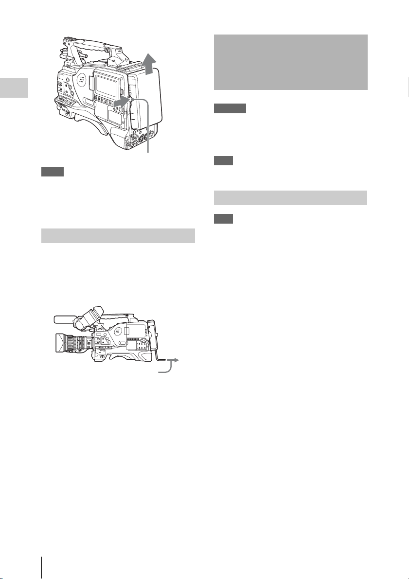
Attaching the Viewfinder
Chapter 2 Preparations
Release button
Notes
• During recording and playback, be careful never to
remove the battery pack.
• Make sure to power the camcorder off before replacing
the battery pack.
Using AC power
When using the AC-DN10 AC adaptor
Mount an AC-DN10 on the camcorder in the
same way as a battery pack, then connect to the
AC power supply.
The AC-DN10 can supply up to 100 W of power.
To an AC outlet
CAUTION
When the viewfinder is attached, do not leave the
camcorder with the eyepiece facing the sun. Direct
sunlight can enter through the eyepiece, be focused in the
viewfinder and cause fire.
Note
The viewfinder is supplied separately.
Attaching the HDVF-20A/C35W
Note
When attaching the viewfinder, make notes of the
following points.
• Be sure to the power off the camcorder before coupling
the viewfinder connector to the camcorder’s VF
connector. If you make this connection when the
camcorder power is on, the viewfinder may not
function properly.
• Couple the viewfinder connector firmly to the
camcorder’s VF connector. If the coupling is loose,
noise may appear on the video or the tally indicator
may not operate properly.
For more information about the connection of the
viewfinder and camcorder, contact a Sony service
representative.
1 1 Loosen the viewfinder left-to-right
positioning ring, 2 attach the
viewfinder to the viewfinder fitting
shoe, and 3 tighten the viewfinder leftto-right positioning ring.
Attaching the Viewfinder
30
 Loading...