

Sony HDW-1800,HDW-D1800 Installation Manual

HD DIGITAL VIDEOCASSETTE RECORDER
HDW-1800
HDW-D1800
INSTALLATION MANUAL
1st Edition
! WARNING
This manual is intended for qualified service personnel only.
To reduce the risk of electric shock, fire or injury, do not perform any servicing other than that
contained in the operating instructions unless you are qualified to do so. Refer all servicing to
qualified service personnel.
! WARNUNG
Die Anleitung ist nur für qualifiziertes Fachpersonal bestimmt.
Alle Wartungsarbeiten dürfen nur von qualifiziertem Fachpersonal ausgeführt werden. Um die
Gefahr eines elektrischen Schlages, Feuergefahr und Verletzungen zu vermeiden, sind bei
Wartungsarbeiten strikt die Angaben in der Anleitung zu befolgen. Andere als die angegeben
Wartungsarbeiten dürfen nur von Personen ausgeführt werden, die eine spezielle Befähigung
dazu besitzen.
! AVERTISSEMENT
Ce manual est destiné uniquement aux personnes compétentes en charge de l’entretien. Afin
de réduire les risques de décharge électrique, d’incendie ou de blessure n’effectuer que les
réparations indiquées dans le mode d’emploi à moins d’être qualifié pour en effectuer d’autres.
Pour toute réparation faire appel à une personne compétente uniquement.
HDW-1800 (SY) Serial No. 10001 and Higher
HDW-1800 (CN) Serial No. 50001 and Higher
HDW-D1800 (SY) Serial No. 10001 and Higher
HDW-D1800 (CN) Serial No. 50001 and Higher
HDW-1800/D1800
CAUTION
Danger of explosion if battery is incorrectly replaced.
Replace only with the same or equivalent type
recommended by the manufacturer.
Dispose of used batteries according to the
manufacturer’s instructions.
ADVARSEL!
Lithiumbatteri-Eksplosionsfare ved fejlagtig
håndtering.
Udskiftning må kun ske med batteri
af samme fabrikat og type.
Levér det brugte batteri tilbage til leverandøren.
ADVARSEL
Lithiumbatteri - Eksplosjonsfare.
Ved utskifting benyttes kun batteri som
anbefalt av apparatfabrikanten.
Brukt batteri returneres
apparatleverandøren.
Vorsicht!
Explosionsgefahr bei unsachgemäßem Austausch
der Batterie.
Ersatz nur durch denselben oder einen vom
Hersteller empfohlenen ähnlichen Typ. Entsorgung
gebrauchter Batterien nach Angaben des
Herstellers.
ATTENTION
Il y a danger d’explosion s’il y a remplacement
incorrect de la batterie.
Remplacer uniquement avec une batterie du même
type ou d’un type équivalent recommandé par le
constructeur.
Mettre au rebut les batteries usagées conformément
aux instructions du fabricant.
VARNING
Explosionsfara vid felaktigt batteribyte.
Använd samma batterityp eller en likvärdig typ
som rekommenderas av apparattillverkaren.
Kassera använt batteri enligt gällande
föreskrifter.
VAROITUS
Paristo voi räjähtää jos se on virheellisesti
asennettu.
Vaihda paristo ainoastaan laitevalmistajan
suosittelemaan tyyppiin.
Hävitä käytetty paristo valmistajan ohjeiden
mukaisesti.
HDW-1800/D1800
1 (P)
Attention-when the product is installed in Rack:
Für Kunden in Deutschland
1. Prevention against overloading of branch circuit
When this product is installed in a rack and is
supplied power from an outlet on the rack, please
make sure that the rack does not overload the supply
circuit.
2. Providing protective earth
When this product is installed in a rack and is
supplied power from an outlet on the rack, please
confirm that the outlet is provided with a suitable
protective earth connection.
3. Internal air ambient temperature of the rack
When this product is installed in a rack, please make
sure that the internal air ambient temperature of the
rack is within the specified limit of this product.
4. Prevention against achieving hazardous
condition due to uneven mechanical loading
When this product is installed in a rack, please make
sure that the rack does not achieve hazardous
condition due to uneven mechanical loading.
5. Install the equipment while taking the operating
temperature of the equipment into consideration
For the operating temperature of the equipment, refer
to the specifications of the Operation Manual.
Entsorgungshinweis: Bitte werfen Sie nur entladene
Batterien in die Sammelboxen beim Handel oder den
Kommunen. Entladen sind Batterien in der Regel dann,
wenn das Gerät abschaltet und signalisiert “Batterie
leer” oder nach längerer Gebrauchsdauer der Batterien
“nicht mehr einwandfrei funktioniert”. Um
sicherzugehen, kleben Sie die Batteriepole z.B. mit
einem Klebestreifen ab oder geben Sie die Batterien
einzeln in einen Plastikbeutel.
For the customers in the Netherlands
Voor de klanten in Nederland
Hoe u de batterijen moet verwijderen, leest u in de
Onderhoudshandleiding.
Gooi de batterij niet weg maar lever deze in als klein
chemisch afval (KCA).
6. When performing the installation, keep the
following space away from walls in order to
obtain proper exhaust and radiation of heat.
Right, Left: 4 cm (1.6 inches) or more
Rear: 40 cm (16 inches) or more
For the customers in Taiwan only
2 (P)
HDW-1800/D1800

Table of Contents
Manual Structure
Purpose of this manual ...........................................................2 (E)
Related manuals ..................................................................... 2 (E)
1. Installation
1-1. Installation Procedure .............................................. 1-1 (E)
1-2. Supplied Accessories ............................................... 1-1 (E)
1-3. Operating Conditions............................................... 1-1 (E)
1-4. Power Supply........................................................... 1-2 (E)
1-4-1. Voltage and Power Requirements .................. 1-2 (E)
1-4-2. Power Cord..................................................... 1-2 (E)
1-5. Installation Space..................................................... 1-3 (E)
1-6. Rack Mounting ........................................................ 1-4 (E)
1-7. Matching Connectors and Cables ............................ 1-9 (E)
1-8. Signal Inputs and Outputs...................................... 1-10 (E)
1-9. Switch Settings on Connector Panel...................... 1-14 (E)
1-10. Switch Settings on Circuit Boards ......................... 1-15 (E)
1-10-1. APR-80 Board .............................................. 1-15 (E)
1-11. Operation Mode Settings ....................................... 1-17 (E)
1-11-1. Operation Procedure of Destination
Selection Mode............................................. 1-17 (E)
1-12. Removing/Reattaching Lower Control
Panel Unit .............................................................. 1-18 (E)
1-13. Switching Search Dial Mode ................................. 1-19 (E)
1-14. Reference System .................................................. 1-20 (E)
1-15. Settings and Adjustment when External
Equipment is Connected ........................................ 1-21 (E)
1-15-1. Settings for Time Code ................................ 1-21 (E)
1-15-2. VTR Constant Values Settings of Editor ..... 1-21 (E)
1-15-3. System Phase Alignment.............................. 1-22 (E)
1-16. Removing/Reattaching Plug-in Board ................... 1-22 (E)
1-17. Taking Out the Cassette in Tape Slacking ............. 1-23 (E)
Appendix A Setting Check Sheet
HDW-1800/D1800
1 (E)

Purpose of this manual
Related manuals
Manual Structure
This manual is the installation manual of the HD Digital Videocassette Recorder
HDW-1800/D1800.
This manual is intended for use by trained system and service engineers, and
provides the information that is required to install (environment, connection information, initial setting, etc.) and the setting check sheet.
Besides this “installation manual”, the following manuals are available for this unit.
..
. Operation Manual (Supplied with this unit.)
..
This manual is necessary for application and operation (and installation) of this
unit.
..
. Maintenance Manual (Available on request)
..
Volume-1 : Service Instruction
Volume-2 : Parts List, Block Diagrams, and Board Layouts
Volume-3 : Schematic Diagrams
These manuals describe the maintenace and service information (service overview, adjustments, board layouts, schematic diagrams, detailed parts list, etc.) for
this unit.
..
. “Semiconductor Pin Assignments” CD-ROM (Available on request)
..
This “Semiconductor Pin Assignments” CD-ROM allows you to search for
semiconductors used in Broadcast and Professional equipment.
The maintenance manual (volume-2) contains a complete list of semiconductors
and their ID Nos., and thus should be used together with the CD-ROM.
Part number: 9-968-546-0X
2 (E)
HDW-1800/D1800
Section 1
Installation
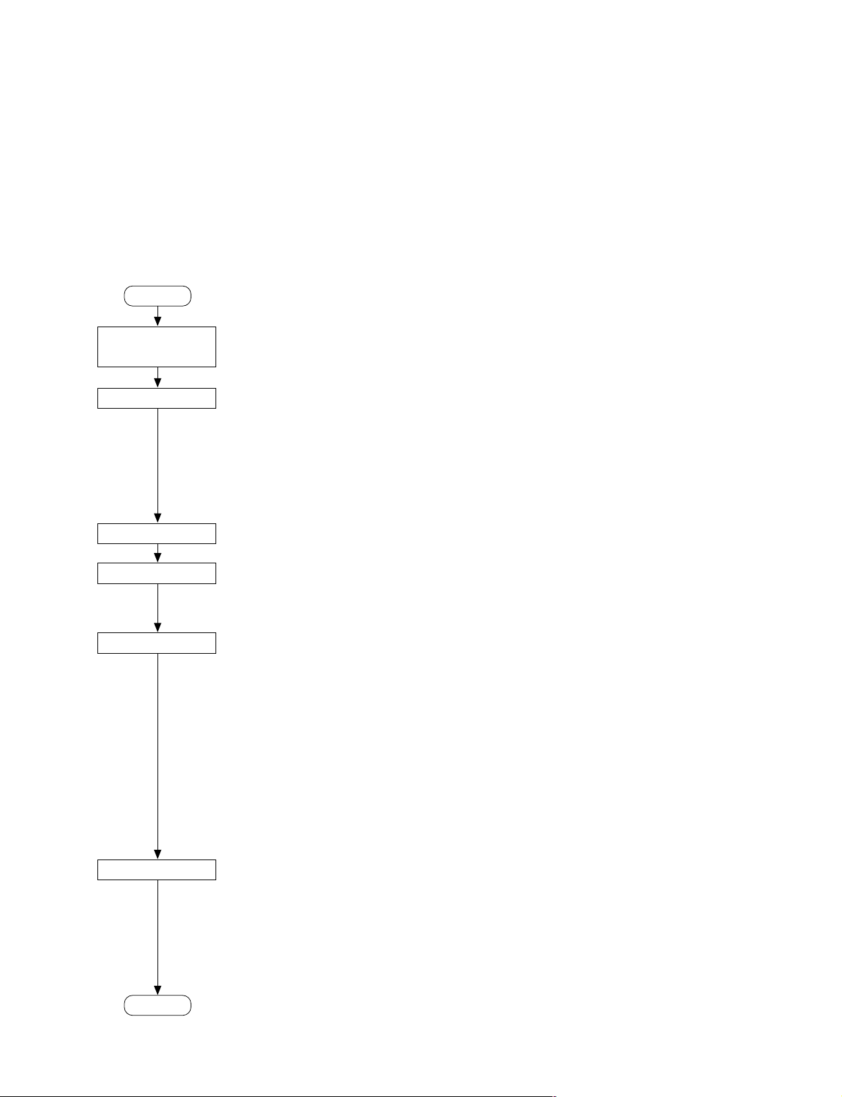
1-1. Installation Procedure
Installation procedure of this unit is shown on the following flowchart.
Refer to each section about detail of each flow.
The operation manual is also required to do *-marked
flow.
Start
Determination of
installation place
Unpacking
n
When the unit is transported, it is required to
pack the unit into the specified new packing
materials.
Do not reuse the packing materials.
Rack mounting
*Connection
*Initial setup
*Operation check
1-3. Operating Conditions
1-4. Power Supply
1-5. Installation Space
1-6. Rack Mounting
1-7. Matching Connectors and
Cables
1-8. Signal Inputs and Outputs
1-9. Switch Settings on Connector
Panel
1-10. Switch Settings on Circuit
Boards
1-11. Operation Mode Settings
1-12. Removing/Reattaching
Lower Control Panel Unit
1-13. Switching Search Dial Mode
1-14. Reference System
1-15. Settings and Adjustment
when External Equipment
is Connected
1-2. Supplied Accessories
. Screws for rack mounting (PSW 4 x 16) ....................... 4
. Operation guide .............................................................. 1
. Operation manual CD-ROM (PDF) ............................... 1
. Installation manual ......................................................... 1
1-3. Operating Conditions
c
Good air circulation is essential to prevent internal heat
build-up. Place the unit in location with sufficient air
circulation.
Do not block the ventilation holes of the cabinet and the
front and rear panels.
Operating temperature: 5 dC to 40 dC
Operating humidity: 25 % to 80 % (non-condensing)
Storage temperature: _20 dC to 60 dC
Locations to avoid:
. Areas where the unit will be exposed to direct sunlight
of any other strong lights.
. Areas near heat sources.
. Dusty areas or areas subject to vibration.
. Areas with strong magnetic field.
. Areas with much electrical noise.
. Areas with much static electricity.
. Areas that is impossible to find a specified room for
installation. (Refer to “1-5. Installation Space”.)
. Areas windtight.
Tilt allowance: Within 30d (Do not slant the front
and rear of the unit more than 30d.)
c
Fix the unit securely to avoid drop when the unit is operated at not-horizontal place.
End
HDW-1800/D1800
n
If an error message appears on the time data
display area, refer to the operation manual.
(For more details, refer to the maintenance
manual volume-1.)
1-1 (E)
1-4. Power Supply
1-4-2. Power Cord
1-4-1. Voltage and Power Requirements
This unit’s power line has a switching regulator.
c
Be sure to operate the unit within the range of following
power voltage.
Power voltage: AC 100 to 240 V ± 10 %
Power frequency: 50 Hz or 60 Hz
Power consumption: Maximum 170 W
(With all of the presumed optional kits.)
Rush current: 10 A (Power voltage 100 V)
33 A (Power voltage 240 V)
n
AC power supply is required a capacity which is commensurate with rush current.
If the capacity of the AC power supply is not enough, the
breaker of AC power of a supply side may operate or this
unit may not operate normally.
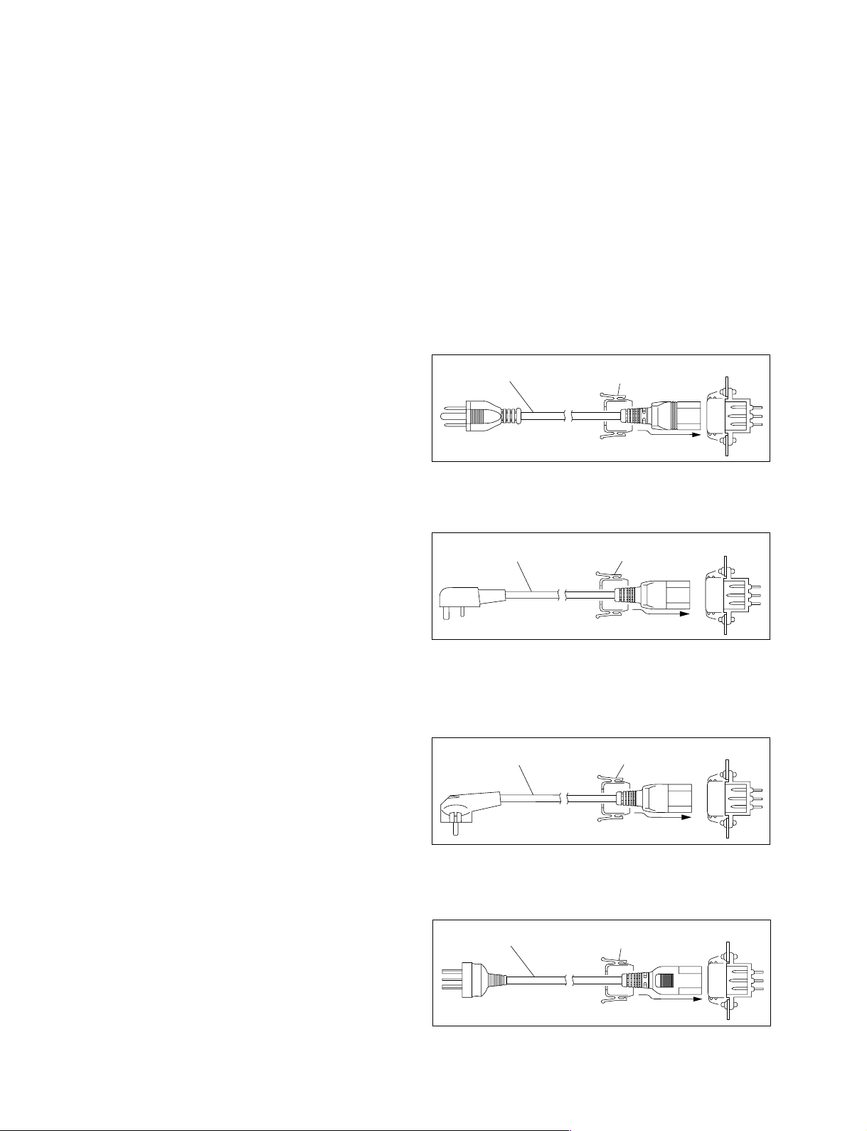
This unit does not come with a power cord.
To get a power cord, please contact your local Sony Sales
Office/Service Center.
w
Use the specified power cord only when connecting the
AC power. Never use a injured power cord.
For customers in the U.S.A. and Canada:
1 Power cord 125 V 10 A (2.4 m): ! 1-551-812-31
2 Plug holder (Brown): 3-613-640-01
1
2
AC inlet
For customers in the United Kingdom:
1 Power cord 250 V 10 A (2.0 m): ! 1-777-823-12
2 Plug holder (Brown): 3-613-640-01
21
AC inlet
For customers in European countries except the United
Kingdom:
1 Power cord 250 V 10 A (2.0 m): ! 1-551-631-15
2 Plug holder (Brown): 3-613-640-01
21
AC inlet
For customers in the China:
1 Power cord 250 V 10 A (1.8 m): ! 1-783-481-42
2 Plug holder (Brown): 3-613-640-01
1
2
AC inlet
If the unit is used in the area except above, please contact
your local Sony Sales Office/Service Center.
1-2 (E)
HDW-1800/D1800
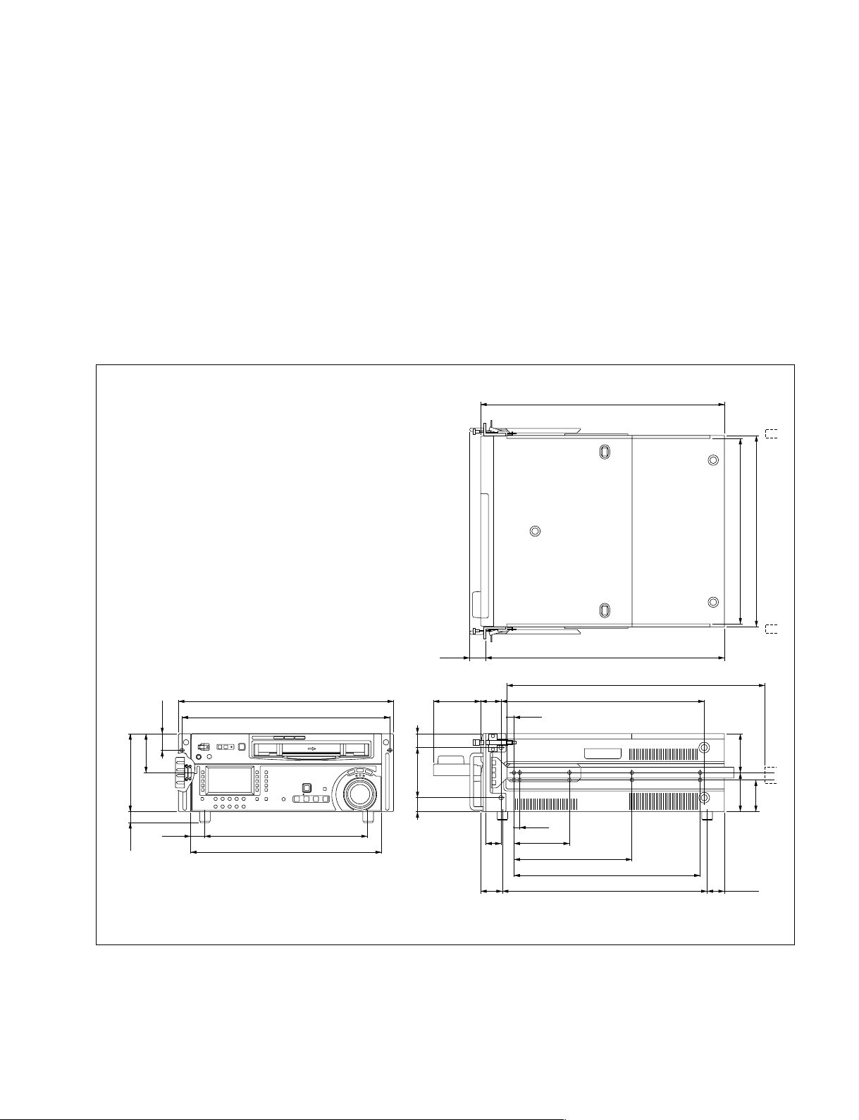
1-5. Installation Space
When installing, the installation space must be secured in
consideration of the ventilation and service operation.
. Do not block the ventilation slots at the left side and
right side panels, and vents of the fans.
. Leave a space around the unit for ventilation.
. Leave more than 40 centimeters of space in the rear of
the unit to secure the operation area.
When the unit is installed on the desk or the like, leave at
least four centimeters of space in the left and right sides.
Leaving 40 centimeters or more of space above the unit is
recommended for service operation.
(Mass of this unit : approx. 22 kg)
Moreover, an air flow that is effective in cooling the unit is
essential. If the ventilation is not enough, the unit may be
damaged because of an increase of the internal temperature.
n
This unit is air-cooled by the five fans. The operation with
the upper lid is removed affects the air cooling by the fans.
Complete the work in a short time as possible when
operating the unit for inspection with the upper lid removed. If it takes a long time, blow to the unit by an
electric fan to cool the unit.
544
481
36.2
87
17419.5
465
36431.5
427
n Remove the feet when rack mounting.
Dimensions when Rack-Mounting
112 3131
48
34
53345.5
577(Maximum traveling distance)
45445105
15.9
12.7
123.8
263.5
415.9
457.5
427(Unit width)
416(Rail-installed width)
8787
70.6
(38.5)
Unit : mm
HDW-1800/D1800
1-3 (E)
1-6. Rack Mounting
Parts Packed in RMM-131
Explains how to mount this unit into a 19-inch standard
rack.
Two positions (center and low) are available to attach the
inner rails of the slide rails to this unit.
Be sure to mount this unit (*) into a rack accurately
following the procedure and notes mentioned below.
*: The center position only is available for the units listed
below.
MSW-A2000 : Serial No. 10001 through 10180
MSW-A2000P : Serial No. 40001 through 40520
w
. To prevent toppling over the rack, fix it on the horizontal
and firm floor securely with bolts, etc.
. When installing the unit in an Outside Broadcasting van,
be sure to fix the unit to the rack using the screws and
ornamental washers supplied with the rack mount kit.
c
. Use the specified rack mount rail.
The use of other rail of low strength may drop the unit
and cause the risk of injury.
. Mount the unit into a rack with a steady posture.
. Slide rails .......................................................... 2
. Rack angles (handles) with lock mechanism ... 2
. Rail brackets ..................................................... 4
. Plate nuts (large) .............................................. 4
. Plate nuts (small) .............................................. 4
. Screws (B4 x 8) ............................................... 8
. Hexagon socket head cap screws ..................... 8
. Flat washers ...................................................... 8
. Screws (RK5 x 14) .......................................... 2
. Ornamental washers ......................................... 2
. L-shaped hexagon wrench ............................... 1
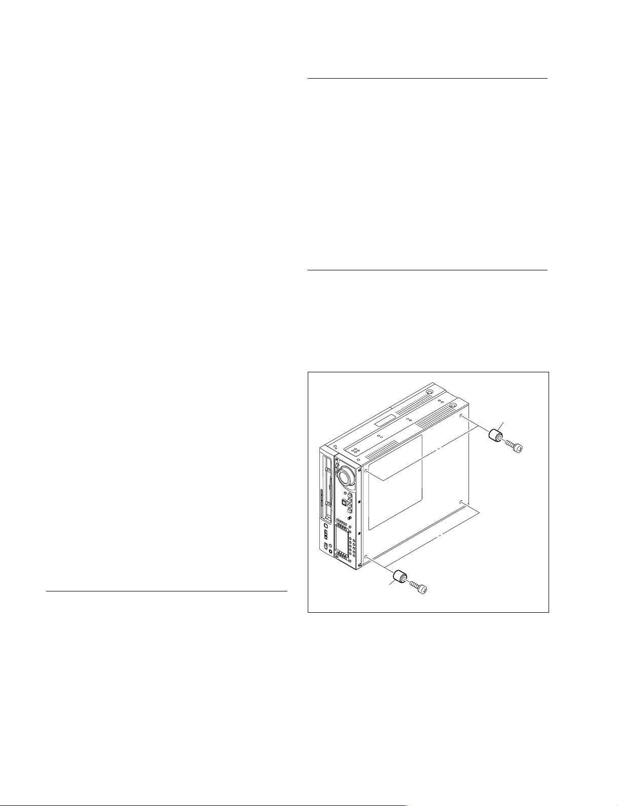
Rack Mounting Procedure
. Removing the feet
1. Set the unit its side panel down.
2. Unscrew the four screws to remove the feet from the
bottom plate of the unit.
3. Set the unit in a horizontal position.
m
. When other equipment with built-in hard disk drive is
already mounted in the same rack for mounting this unit,
turn off the power of the equipment before mounting this
unit.
. Connect long enough cables on the connector panel,
considering that the unit is pulled out from the rack.
. Do not operate this unit without the upper lid and bottom
plate except when servicing it.
. Adjust the temperature inside the rack within the range
of the unit’s operating temperature.
(Refer to Section 1-3.)
Specified Rack Mount Kit
RMM-131 (Optional accessory)
m
. When mounting this unit into Sony LMS (Library
Management System) VTR console, it is necessary to
modify the VTR console.
. When mounting this unit into Flexicart, be sure to use
the specified kit below.
VTR Mounting kit: BKFC-53/3
. The RMM-130 rack mount kit also can be used for the
center position.
Feet
PS4 x 20
Feet
PS4 x 20
n
Keep these screws and the feet.
When operating the unit after demounting it from the rack,
be sure to reattach the feet.
Tightening torque: 98 x 10_2 N . m {10 kgf . cm}
1-4 (E)
HDW-1800/D1800

. Attaching the inner rails
B4 x 6
B4 x 6
B4 x 6
PSW4 x 16
PSW
4 x 16
Rack angle
Rack angle
Rack angle
Fig.1 For RMM-130 (Left side)
4. Pull out the inner rails from the two intermediate rails.
5. While pressing the stopper of the inner rail in the
direction of the arrow A in the figure, pull the inner
rail out in the direction of the arrow B.
Intermediate rail
. Attaching the rack angles (handles)
8. Remove the four screws from both sides (left and
right) of the unit.
Inner rail
Outer rail
A
Stopper
B
6. Remove the ten screws from both sides (left and right)
of the unit as shown in the figure below.
7. Attach the two inner rails to both sides (left and right)
of unit with the removed screws in the step 6.
Tightening torque: 120 x 10_2 N . m {12.2 kgf . cm}
m
. Be sure to use the (B4 x 6) screws when attaching
the inner rail. The use other-sized screws may cause
a malfunction.
. Pay attention not to fasten the screws to the screw
holes other than actually used screw holes for fixing
the inner rails on both sides of the unit.
If unnecessary screws are fastened, rack mounting
will be unenabled.
Inner rail
n
Keep these screws (B4 x 6).
Be sure to use these screws when directly fixing the
side panels without the rack angles.
The use of longer screws such as the screws (PSW 4 x
16) for fixing the rack angles of RMM-130 will cause
a malfunction of the unit.
9. Attach the two rack angles to both sides (left and right)
of the unit with the four screws (PSW4 x 16).
Tightening torque: 120 x 10_2 N . m {12.2 kgf . cm}
n
. For RMM-131, screws with stop washers are used
for fixing the rack angles.
. For RMM-130, use the supplied screws PSW4 x 16
as shown in Fig. 1.
B4 x 6
n
When replacing a 5U size Sony VTR with this unit, attach
the inner rails to the low position, so that the bottom of the
unit becomes same as that of the 5U size VTR.
HDW-1800/D1800
Inner rail
B4 x 6
1-5 (E)
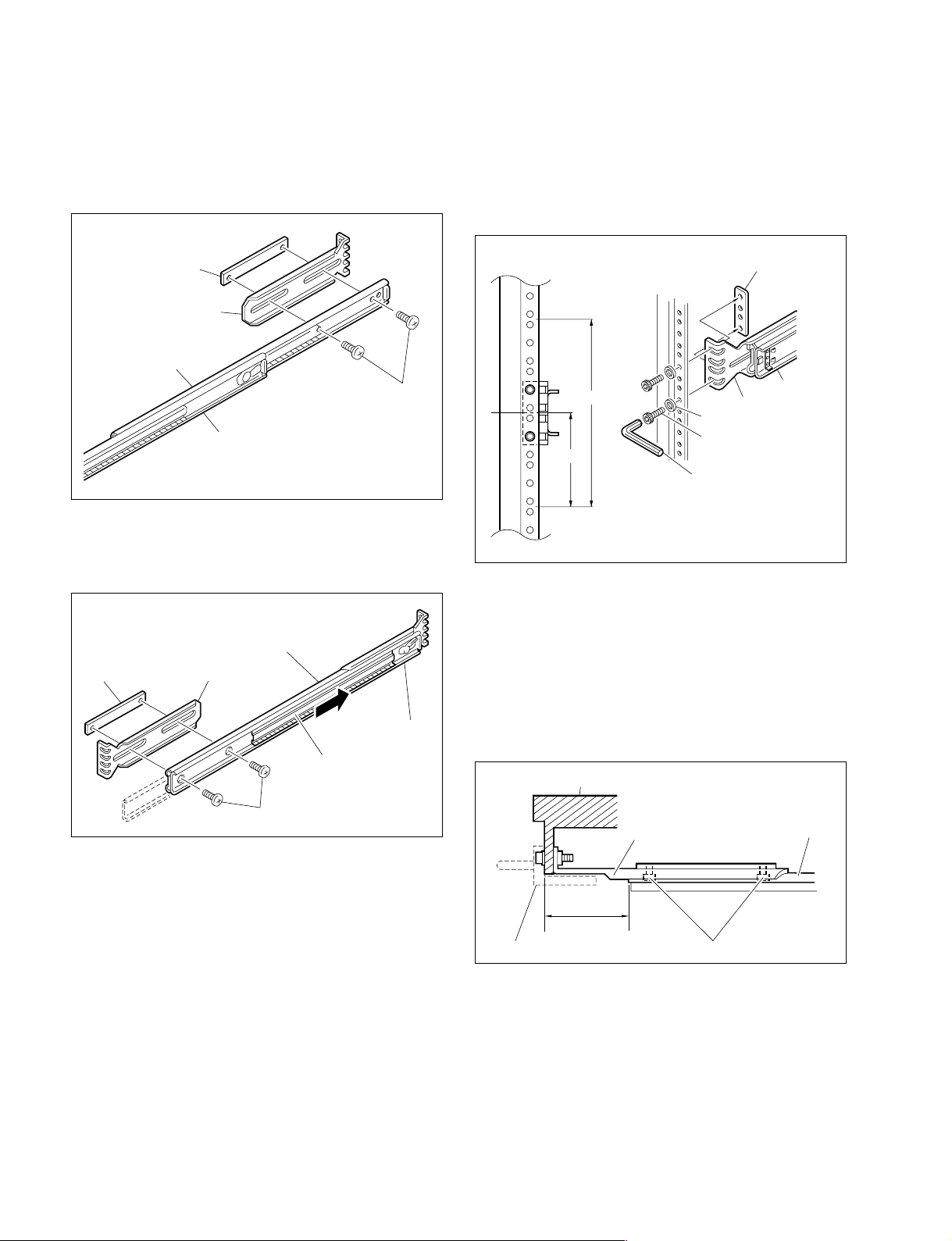
. Loosely attaching the rail brackets
10. Slide the intermediate rail as shown in the figure, and
then loosely attach the rear rail bracket to the outer rail
with a plate nut (large) and the two screws.
. Attaching the outer rails
12. Loosely attach the two outer rails to the middle of the
4U space in the rack for mounting this unit, with the
eight hexagon socket head cap screws, eight flat
washers, and four plate nuts (small).
Plate nut (large)
Rail bracket
Outer rail
B4 x 8
Intermediate rail
11. Slide the ball retainer in the direction of the arrow, and
then loosely attach the front rail bracket to the outer
rail with a plate nut (large) and the two screws.
Outer rail
Plate nut (large)
Rail bracket
Intermediate rail
Ball retainer
Plate nut (small)
Rail
By 4U
2U
L-shaped hexagon wrench
Rail bracket
Flat washer
Hexagon socket
head cap screw
13. As shown in the following figure, adjust each frontside position of the outer rails on both sides (left and
right) so that the distance from the surface of the rack
to the tip of the rail becomes within the range of 50 to
55 millimeters.
14. Fully tighten the eight screws (B4 x 8) fixing the four
rail brackets.
Tightening torque: 120 x 10_2 N . m {12.2 kgf . cm}
Rack
1-6 (E)
B4 x 8
Rack angle
50 to 55 mm
Rail bracket
Outer rail
B4 x 8
HDW-1800/D1800
 Loading...