

Sony HDVF-L750, HDVF-L770 Operation Manual

LCD COLOR VIEWFINDER
HDVF-L750
HDVF-L770
OPERATION MANUAL [English]
1st Edition

Table of Contents
Precautions................................................ 3
Overview .................................................... 4
Functions of Parts and Controls.............. 5
Attaching to the Camera........................... 8
Turning on the Viewfinder...................... 10
Adjusting the Viewfinder Position......... 10
Adjusting the Height and Tilting/
Panning...........................................10
Adjusting the Front-Back Position
(HDVF-L770 only) ........................12
Adjusting the Screen .............................. 13
Attaching Accessories............................ 14
Attaching a Hood .....................................14
Attaching a Number Plate........................15
Using the Focus Assist Function .......... 15
PEAKING PLUS Function......................15
MAGNIFICATION Function ..................17
Using the Menu........................................ 18
Basic Menu Operations............................18
List of Menu Items...................................20
Error Message ......................................... 26
Specifications..........................................26
Table of Contents /
2

Precautions
Handling the screen
• The LCD panel fitted to this unit is manufactured with
high precision technology, giving a functioning pixel
ratio of at least 99.99%. Thus a very small proportion of
pixels may be “stuck”, either always off (black), always
on (red, green, or blue), or flashing. In addition, over a
long period of use, because of the physical
characteristics of the liquid crystal display, such
“stuck” pixels may appear spontaneously. These
problems are not a malfunction.
These phenomena have no effect on the camera’s
output signals.
• Do not leave the screen facing the sun as it can damage
the screen. Take care when you use the unit outdoors.
• Do not push or scratch the screen. Do not place a heavy
object on the screen. This may cause the screen to lose
uniformity.
• An afterimage may appear when a still image is
displayed continuously. Turn the viewfinder off when it
is not used for a long time.
• When using the viewfinder in low temperature, the
moving image resolution deteriorates right after the
viewfinder is turned on.
• Do not apply strong shock to the screen. This may
damage the internal structure or deform the cabinet.
On installation
• Allow adequate air circulation to prevent internal heat
build-up.
Do not place the unit on surfaces (rugs, blankets, etc.)
or near materials (curtains, draperies) that may block
the ventilation holes.
• Do not install the unit in a location near heat sources
such as radiators or air ducts, or in a place subject to
direct sunlight, excessive dust, mechanical vibration or
shock.
On dew condensation
If the unit is suddenly taken from a cold to a warm
location, or if ambient temperature suddenly rises,
moisture may form on the outer surface of the unit and/or
inside of the unit. This is known as condensation. If
condensation occurs, turn off the unit and wait until the
condensation clears before operating the unit. Operating
the unit while condensation is present may damage the
unit.
Disposal of the unit
Do not dispose of the unit with general waste.
Do not include the unit with household waste.
When you dispose of the unit, you must obey the law in
the relative area or country.
Handling and maintenance of the screen
The surface of the screen is specially coated to reduce
image reflection. Make sure to observe the following
points as improper maintenance procedures may impair
the screen’s performance. In addition, the screen is
vulnerable to damage. Do not scratch or knock against it
using a hard object.
• Be sure to turn off the power of the connected
equipment before performing maintenance.
• The surface of the screen is specially coated. Do not
attach adhesive objects, such as stickers, on it.
• The surface of the screen is specially coated. Do not
touch the screen directly.
• Wipe the screen surface gently with a soft dry cloth to
remove dirt.
• Stubborn stains may be removed with a soft cloth
slightly dampened with a mild detergent solution.
• The screen may become scratched if a cloth is dusty.
• Never use strong solvents such as alcohol, benzene,
thinner, acidic or alkaline detergent, detergent with
abrasives, or chemical wipe as these may damage the
screen.
• Use a blower to remove dust from the screen surface.
Precautions
3

Overview
The HDVF-L750/HDVF-L770 is a 7.0-inch LCD
viewfinder.
This viewfinder has the following features.
High resolution and wide visual angle
The viewfinder uses a 7.0-inch Full-HD resolution LCD
panel for a resolution of 1920 × 1080 and a wide visual
angle.
Focus Assist function
This viewfinder comes with an original Focus Assist
function to support accurate focusing.
• Peaking function
Edge enhancement can be performed in the horizontal/
vertical direction on the entire of the screen. (Only in
the horizontal direction for the previous HDVF.)
• Peaking Plus function
Edge enhancement can be performed on the object that
is specified using a color, area selected, or both.
• Image magnification function
A portion of the image can be magnified vertically and
horizontally while displaying the image for composing
the picture.
Easy return function
You can switch between the camera image from the
supplied connecting cable and the SDI image from the
external input by operating the assignable switch.
Waveform Monitor function
The input signal waveform can be easily displayed in the
sub display.
Assignable switch
Assignable switches are provided on the front (2
switches) and on the left and right handles (2 switches
each, HDVF-L770 only) for frequently used functions.
Tally indicators
The viewfinder comes with three tally indicators (red,
green, and yellow), which light up in response to tally
signals.
Check the connected camera to identify whether the use
of the yellow tally indicator is supported.
Superior operation
• Screen positioning mechanism
HDVF-L770:
Use of a counterbalance mechanism to optimize weight
distribution of the panel and link arms allows
immediate screen tilting and lifting with a light
operational feeling.
HDVF-L750:
The lift mechanism is equipped while being light
(approx. 1.7 kg). This mechanism can perform panning,
tilting, and height adjustment.
• Large handles equipped with assignable switches
(HDVF-L770 only)
Large handles each equipped with two assignable
switches are provided for the left and right sides of the
screen. These do not hinder the operator’s view, and
they offer comfortable operation.
Supplied indoor hood and optional VFH790 outdoor hood
The indoor hood is supplied. The optional VFH-790
outdoor hood offers superior shading ability.
Guide frame displaying function
The guide marker for matching the horizontal/vertical
line can be displayed.
Switching to preset adjustment settings
Brightness, contrast, peaking, and chroma levels can be
preset for selection through an assignable switch or a
menu operation.
False color function
Display signal levels using different colors. When you
use the false color function, image signals are displayed
in black and white, and colors are added based on the
signal levels.
Overview
4
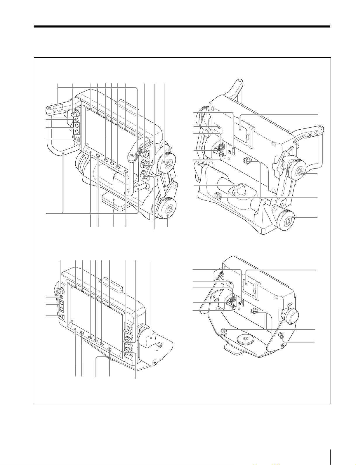
Functions of Parts and Controls
HDVF-L770
8 9 qa67435210
qs
qd
qf
qg
HDVF-L750
qs
qd
qf
qh qj qlqk
8 9 qa6743520
ws
wd
wf
wg
wh
wj
waw;
ws
wd
wf
wg
wh
wk
wl
e;
ea
wk
qh qj qlqk
w;
e;
es
Functions of Parts and Controls
5

a ASSIGN. (assignable) L1/L2/R1/R2 switches
(HDVF-L770 only)
Can be used to store frequently used functions.
The switches ASSIGN. L1 and ASSIGN. L2 are located
on the left handle, and ASSIGN. R1 and ASSIGN. R2 are
located on the right handle.
Storing a function is performed using “ASSIGN. L1,”
“ASSIGN. L2,” “ASSIGN. R1,” or “ASSIGN. R2” in the
FUNCTION menu.
i BRIGHT control
Adjusts the brightness of the viewfinder image.
This control does not affect the output signal of the
camera.
j CONTRAST control
Adjusts the contrast of the viewfinder image.
This control does not affect the output signal of the
camera.
b MENU control
Turn the control to select a menu item, and then press the
control to confirm the selection. Use with the MENU
switch to set various functions.
When the menu is not displayed, pressing this control
shows the status information of the viewfinder on the
screen.
For details on operations, see “Using the Menu” on page
18.
c PEAKING PLUS indicator (blue)
Lights up when “PEAKING MODE” in the PEAKING
menu is set to “PLUS.”
d MAG (magnification) indicator (amber)
Lights up when the displayed image is magnified (when
the ASSIGN. switch of the MAGNIFICATION function
is set to “ON,” or “MAGNIFICATION” in the
MAGNIFICATION menu is set to “ON”).
e G TALLY indicator (green)
Lights up when the green tally signal is input.
f R TALLY indicator (red)
Lights up when the red tally signal is input.
k Tilt-lock knob
HDVF-L770:
Turn this knob in the direction of the arrow indicated on
the knob to secure the tilting position of the viewfinder.
HDVF-L750:
Turn this knob clockwise to secure the tilting position of
the viewfinder.
l MENU switch
Displays the menu. Use with the MENU control to set
various functions.
When the menu is not displayed and this switch is pressed
and held for three seconds or more, “VR LOCK” appears.
This locks the BRIGHT, CONTRAST, and PEAKING
controls at their current settings, preventing accidental
operation. To unlock the controls, press this switch for
three seconds or more again so that “VR UNLOCK”
appears.
For details on operations, see “Using the Menu” on page
18.
m ASSIGN. (assignable) 1/2 switches
Can be used to store frequently used functions.
Storing a function is performed using “ASSIGN.1” and
“ASSIGN.2” in the FUNCTION menu.
g Y TALLY indicator (yellow)
Lights up when the yellow tally signal is input.
h BATT (battery) indicator (red)
Lights up or flashes, to indicate the status of the battery
attached to the camera as follows.
Lit: The battery is drained.
Flashing: The voltage of the battery has dropped below
the threshold value.
To prevent camera from shutting down, change the
battery as soon as possible after this indicator begins
flashing.
The threshold battery voltage value at which this
indicator begins flashing can be set by the camera. For
details, refer to the manual for the camera.
Functions of Parts and Controls
6
n POWER switch
Turns off the power of the LCD panel and goes into a
power-saving mode when SAVE is selected.
o Handles (HDVF-L770 only)
Use the handles to move the viewfinder’s screen.
p STATUS indicator (amber)
Shows the current status of the viewfinder.
Blinking in intervals of 0.5 seconds: A problem is
detected during self-diagnosis.
An error message (see page 26) may be displayed at the
same time. Turn off the power and contact your Sony
service representative.

q (attention) indicator (amber)
Lights up when the camera detects certain conditions. The
conditions under which the indicator lights up are
specified on the camera.
y SDI IN connector (BNC type)
When using monitor mode, connect this to the SDI OUT
connector on the camera or external device using a BNC
cable.
For details on how to set up and verify the conditions
under which the indicator lights up, refer to the
operation manual of the camera in use.
r Mounting wedge
To attach the viewfinder to the camera, mount the
viewfinder in the V-wedge shoe attachment attached on
top of the camera.
For attachment, see “Attaching to the Camera” on page
8.
s Auxiliary indicator
Is not currently used.
t PEAKING control
Adjusts the sharpness of the viewfinder image.
Turn the control clockwise to make the edges sharper.
This control does not affect the output signal of the
camera.
u Lift-lock knob (HDVF-L770 only)
Turn this knob in the direction of the arrow indicated on
the knob to fix the height of the viewfinder.
v CAM connector (26-pin rectangular type)
Connect this to the VF connector on the camera using the
supplied connecting cable (26-pin).
w INPUT switch
Switches the input signal.
CAM: Inputs signals from the CAM connector.
SDI: Inputs signals from the SDI IN connector (monitor
mode).
For details on supported formats, see “Specifications” on
page 26.
z DC IN connector
When power cannot be supplied via CAM connector,
connect to an external power supply (DC 10.5 V to 17.0
V). In this case, contact your Sony service representative.
wj COUNTER BALANCE control (HDVF-L770 only)
Adjust the counterbalance for the screen.
Turning the control toward + increases counterbalance. If
the control movement is too tight, lift the screen then turn
the control.
wk Up-tally lamp (red)
The supplied number plate can be attached to this.
The lamp lights up when the red tally signal is input.
wl Tilt friction adjustment knob (HDVF-L770 only)
Adjusts the friction in the tilting mechanism.
Turning the knob toward + increases the friction, and
toward – decreases the friction.
e; Cable clamp
Clamps the supplied connecting cable.
ea Lift friction adjustment knob (HDVF-L770 only)
Adjusts the friction in the lift mechanism.
Turning the knob toward + increases the friction, and
toward – decreases the friction.
es Lift fixing screw (HDVF-L750 only)
Adjusts the height of the viewfinder in two levels.
x CAM connector (round-type, 20-pin)
Connects to the camera’s VF connector using the
supplied connecting cable (20-pin).
CAUTION
When you connect the unit to peripheral device, use the
supplied cable to prevent malfunction due to radiation
noise.
Note
Use a round-type 20-pin connector when connecting to
the CA4000.
Functions of Parts and Controls
7
Attaching to the Camera
Attach the V-wedge shoe attachment to the camera and
attach the viewfinder to the V-wedge shoe attachment.
Notes
• When attaching the viewfinder to the camera or
removing it from the camera, be sure to lock the
viewfinder in its standard position.
• When removing the viewfinder from the camera, be
sure to secure the tripod with its tilt-lock mechanism
and hold the viewfinder firmly.
Be careful not to fall or drop the viewfinder and camera.
• When attaching the V-wedge shoe attachment, be sure
to use the supplied hexagonal screws.
• When attaching the viewfinder to the HXC-D70 or
PMW-320/350/400/500, use the shoe conversion
bracket (supplied) (see page 9). (HDVF-L750 only)
For how to change the position of the viewfinder attached
to the camera, see “Adjusting the Viewfinder Position”
on page 10.
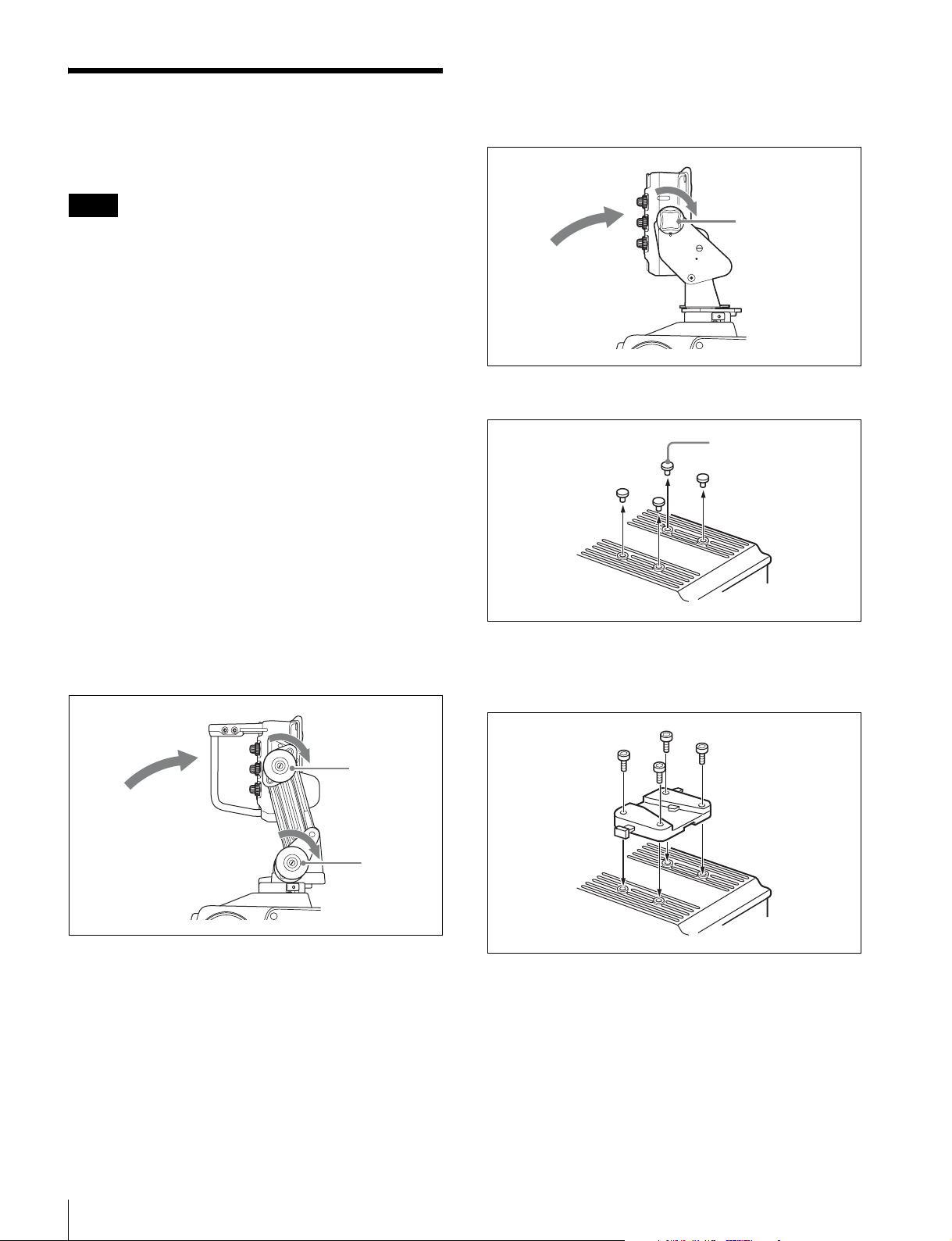
HDVF-L750:
Adjust the height of the viewfinder to the position of
the illustration below, then fix the viewfinder screen
in the standard position by turning the tilt-lock knob.
1
Standard position:
The screen’s height
and position are
fixed fully back, as
illustrated.
2
Tilt-lock knob
3 Remove the four plastic caps from the camera.
Plastic caps
1 Reset the viewfinder to the standard position.
2 HDVF-L770:
Fix the viewfinder screen in the standard position by
turning the tilt-lock knob and lift-lock knob in the
direction of the arrow indicated on each knob
(toward the lock position).
1
Standard position:
The screen’s height
and position are
fixed fully back, as
illustrated.
2
Tilt-lock knob
2
Lift-lock knob
4 Attach the supplied V-wedge shoe attachment to the
camera using the supplied hexagonal wrench and
four socket head cap screws (4 ×12).
Attaching to the Camera
8
5 Mount this viewfinder firmly in the V-wedge shoe
attachment.
There is an audible click when the viewfinder snaps
into the attachment.
HDVF-L770
To detach the viewfinder from the camera
Pull the lever and push down the button while pulling the
viewfinder toward you, as shown in the figure below.
6 Connect the CAM connector to the camera’s VF
connector.
Clamp the connecting cable with the cable clamp as
shown in the following figure.
HDVF-L770
Cable clamp
Button
2
1
HDVF-L770
Lever
Attaching the shoe conversion bracket
(HDVF-L750 only)
When attaching the viewfinder to the HXC-D70 or
PMW-320/350/400/500, use the shoe conversion bracket
(supplied).
1 Remove the cover on the handle of the camera, then
attach the shoe conversion bracket (supplied) to the
camera by using the screws (3×10 screws (4),
supplied).
To the camera’s
VF connector
Notes
• Fix the connecting cable while adjusting the cable
length so that the connecting cable is not caught when
adjusting height, tilting, or panning.
• When gathering the cables together, use the supplied
spiral tube.
• When using the connecting cable (26-pin), make sure
not to tighten the two cable fixing screws too tightly.
Connecting cable
When moving the viewfinder attached to
the camera
Reset the viewfinder screen to the standard position and
fix it in place.
2 Attach the V-wedge shoe attachment to the shoe
conversion bracket by using the hexagonal wrench
and socket head cap screws (4×12 screws (4)).
Attaching to the Camera
9
 Loading...