

Sony VFH-990, HDVF-C950W Maintenance Manual

HD ELECTRONIC VIEWFINDER
HDVF-C950W
OUTDOOR HOOD
VFH-990
MAINTENANCE MANUAL
1st Edition
Serial No. 100001 and Higher

! WARNING
This manual is intended for qualified service personnel only.
To reduce the risk of electric shock, fire or injury, do not perform any servicing other than that
contained in the operating instructions unless you are qualified to do so. Refer all servicing to
qualified service personnel.
! WARNUNG
Die Anleitung ist nur für qualifiziertes Fachpersonal bestimmt.
Alle Wartungsarbeiten dürfen nur von qualifiziertem Fachpersonal ausgeführt werden. Um die
Gefahr eines elektrischen Schlages, Feuergefahr und Verletzungen zu vermeiden, sind bei
Wartungsarbeiten strikt die Angaben in der Anleitung zu befolgen. Andere als die angegeben
Wartungsarbeiten dürfen nur von Personen ausgeführt werden, die eine spezielle Befähigung
dazu besitzen.
! AVERTISSEMENT
Ce manual est destiné uniquement aux personnes compétentes en charge de l’entretien. Afin
de réduire les risques de décharge électrique, d’incendie ou de blessure n’effectuer que les
réparations indiquées dans le mode d’emploi à moins d’être qualifié pour en effectuer d’autres.
Pour toute réparation faire appel à une personne compétente uniquement.
HDVF-C950W

Table of Contents
Manual Structure
Purpose of this manual ........................................................... 3 (E)
Relative manual ...................................................................... 3 (E)
1. Service Overview
1-1. Board Layout ........................................................... 1-1 (E)
1-2. Matching Connectors and Cables ............................ 1-1 (E)
1-2-1. Cable Input/Output Signals ............................ 1-1 (E)
1-2-2. VF Connecting Cable ..................................... 1-2 (E)
1-3. Circuit Overview ..................................................... 1-3 (E)
1-4. List of Tools, Used Equipment, and
Adjustment Equipment ............................................ 1-4 (E)
1-5. Firmware and Software ............................................ 1-5 (E)
1-5-1. Checking the ROM and Software Version ..... 1-5 (E)
1-5-2. Writing and Rewriting PLD Internal Data ..... 1-5 (E)
1-6. Description of On-board Switches ........................... 1-7 (E)
1-7. Removal/Installation of Main Parts ......................... 1-8 (E)
1-7-1. Removing LCD Module ................................. 1-8 (E)
1-7-2. Removing the LE-317 Board ....................... 1-10 (E)
1-7-3. Removing the PR-292 Board ....................... 1-10 (E)
1-7-4. Removing the RE-237 Board ....................... 1-11 (E)
1-7-5. Removing the LE-315 Board ....................... 1-11 (E)
1-7-6. Removing the LE-316 Board ....................... 1-12 (E)
1-7-7. Removing the SW-1298 Board .................... 1-13 (E)
1-7-8. Removing the VR-315 Board ....................... 1-13 (E)
1-7-9. Removing the Harness (VF) ......................... 1-14 (E)
1-8. Extending the Circuit Board .................................. 1-15 (E)
1-8-1. Service Position ............................................ 1-15 (E)
1-8-2. RE-237 Board ............................................... 1-15 (E)
1-9. Fuse and IC Link Replacement .............................. 1-16 (E)
1-10. Unleaded Solder ..................................................... 1-16 (E)
2. Setting Menu
2-1. Setting Menu ............................................................ 2-1 (E)
2-2. TOP Menu ............................................................... 2-2 (E)
2-3. OPERATION Menu ................................................ 2-3 (E)
2-4. SERVICE Menu ...................................................... 2-3 (E)
3. Electrical Alignment
3-1. Preparation ............................................................... 3-1 (E)
3-1-1. Description of Switches, Controls, and
Menu Settings ................................................. 3-1 (E)
3-1-2. Used Equipment ............................................. 3-1 (E)
3-1-3. Connection ..................................................... 3-1 (E)
3-1-4. Format Settings .............................................. 3-1 (E)
3-2. Inverter Power Supply Voltage Adjustment ............ 3-2 (E)
3-3. Brightness Initial Adjustment .................................. 3-2 (E)
3-4. Color Temperature Adjustment ............................... 3-2 (E)
3-5. Brightness Final Adjustment ................................... 3-3 (E)
4. Spare Parts
4-1. Notes on Repair Parts ..................................................... 4-1
4-2. Exploded Views .............................................................. 4-2
4-3. Electrical Parts List .........................................................4-6
4-4. Packing Materials & Supplied Accessories ..................4-19
5. Semiconductor Pin Assignments
6. Block Diagrams
HDVF-C950W
Overall ............................................................................6-2
RE-237 ............................................................................6-3
1 (E)

7. Schematic Diagrams
LE-315 ............................................................................ 7-1
LE-316 ............................................................................ 7-1
LE-317 ............................................................................ 7-2
PR-292 ............................................................................ 7-3
RE-237 ..........................................................................7-10
SW-1298 .......................................................................7-12
SW-1299 .......................................................................7-12
VR-315 .........................................................................7-12
Frame Wiring ................................................................7-13
8. Board Layouts
LE-315 ............................................................................ 8-2
LE-316 ............................................................................ 8-2
LE-317 ............................................................................ 8-2
PR-292 ............................................................................ 8-4
RE-237 ............................................................................8-5
SW-1298 .........................................................................8-5
SW-1299 .........................................................................8-5
VR-315 ...........................................................................8-5
2 (E)
HDVF-C950W

Purpose of this manual
Relative manual
Manual Structure
This manual is the maintenance manual for HD Electronic Viewfinder HDVFC950W. This manual describes the information items necessary when the unit is
supplied and installed, items that premise the service based on the components parts
such as service overview, electrical alignment, spare parts lists, block diagram and
schematic diagrams, assuming use of system and service engineers.
Besides this maintenance manual the following manual is available for this unit.
..
. Operation Manual (supplied with this unit)
..
This manual is necessary for application and operation of this unit.
. “Semiconductor Pin Assignments” CD-ROM (Available on request)
This “Semiconductor Pin Assignments” CD-ROM allows you to search for
semiconductors used in Broadcast and Professional equipment.
The maintenance manual contains a complete list of semiconductors and their ID
Nos., and thus should be used together with the CD-ROM.
Part number: 9-968-546-0X
HDVF-C950W
3 (E)

Section 1
Service Overview
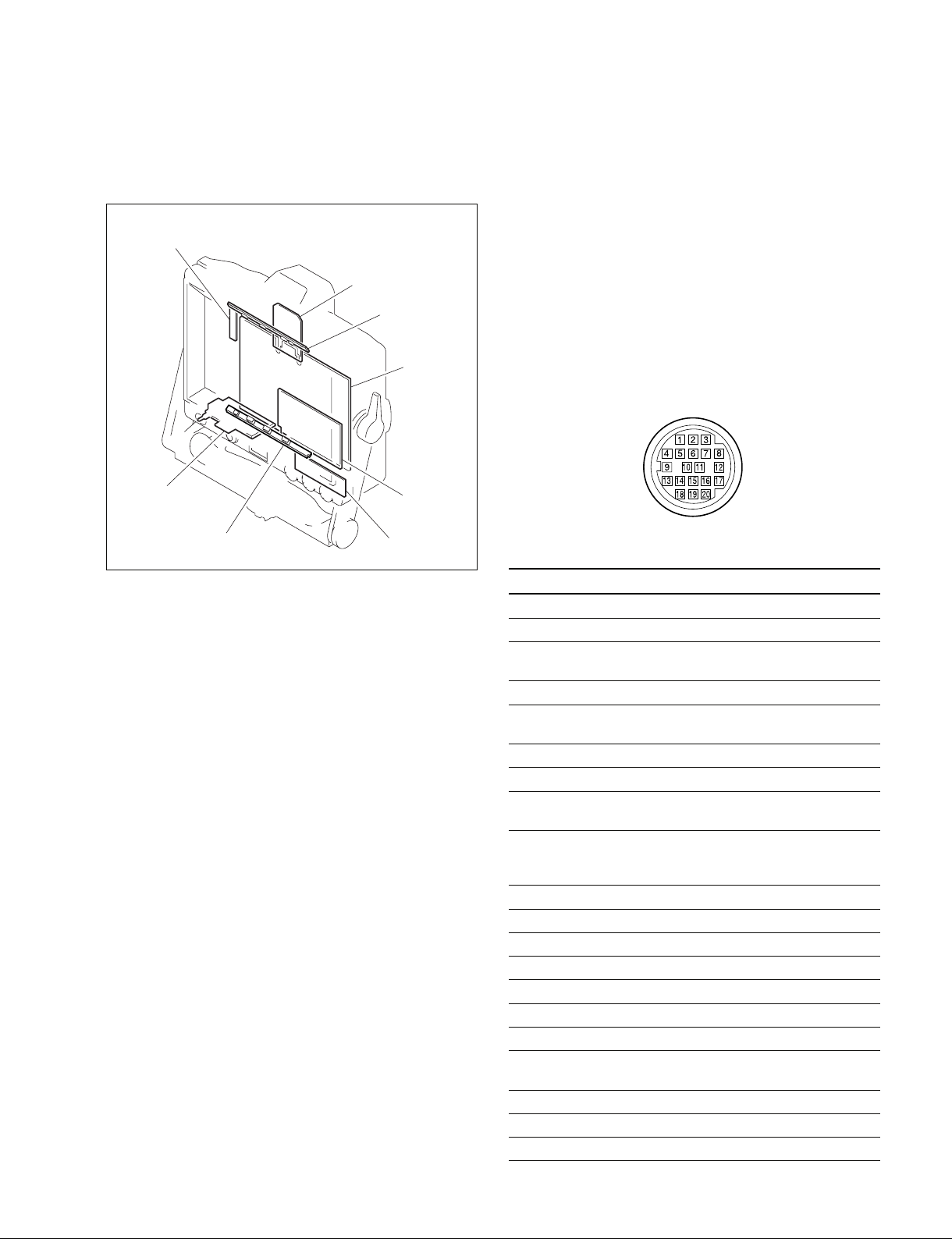
1-1. Board Layout 1-2. Matching Connectors and Cables
Use the included VF connection cable when connecting to
SW-1299
the camera for installation or servicing.
SW-1298
LE-316
LE-317
LE-315
PR-292
RE-237
VR-315
1-2-1. Cable Input/Output Signals
The VF connection cable input/output signals are as
follows.
. CAMERA (20-pin Male)
(External view)
No. Signal I/O Specifications
1 S-DATA IN/OUT TTL level
2 NC No connection
3 POWER OFF IN ON : OPEN
OFF : GND
4 SCK IN TTL level
5 COLOR/MONO OUT MONO : GND
COLOR : OPEN
6 NC No connection
7 NC No connection
8 G TALLY IN ON : +5 V
OFF : GND
9 PEAKING CTL OUT 0 V to +5 V
0 V : PEAKING OFF
+5 V : PEAKING MAX
10 NC No connection
11 NC No connection
12 Y VIDEO IN 1.0 Vp-p, Zi=75 Z
13 VIDEO GND _ GND for VIDEO
14 Pb VIDEO IN 0.7 Vp-p, Zi=75 Z
15 Pr VIDEO IN 0.7 Vp-p, Zi=75 Z
16 NC No connection
17 R TALLY IN ON : +5 V
OFF : GND
18 NC No connection
19 UNREG GND _ GND for UNREG
20 UNREG IN +10.5 V to 17 V
HDVF-C950W
1-1 (E)
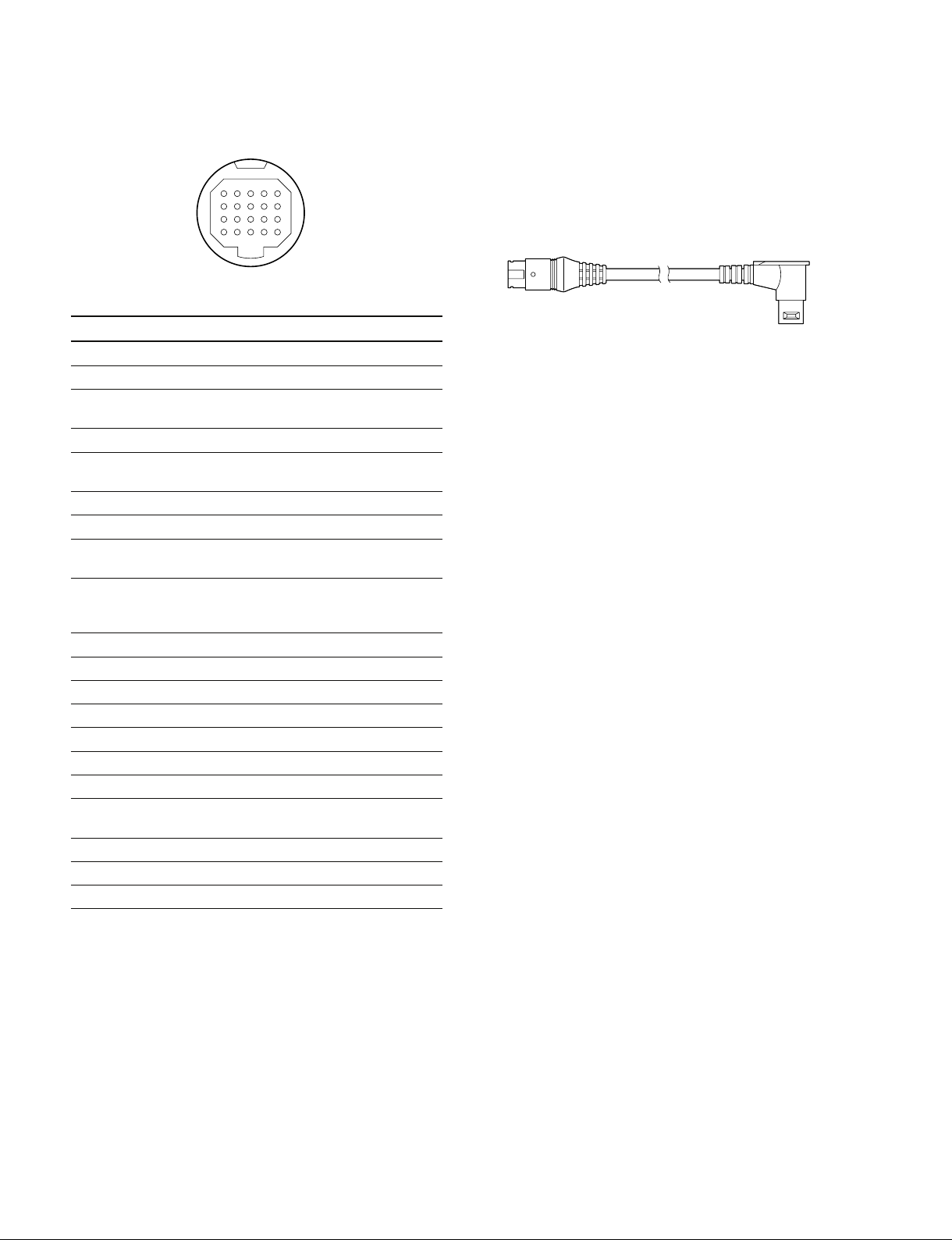
. VF (20-pin Male)
5
10
15
20
1
6
11
16
(External view)
1-2-2. VF Connecting Cable
This cable is used for connecting the main unit to the
camera.
1-830-631-11
No. Signal I/O Specifications
1 S-DATA IN/OUT TTL level
2 NC No connection
3 POWER OFF IN ON : OPEN
OFF : GND
4 SCK IN TTL level
5 COLOR/MONO OUT MONO : GND
COLOR : OPEN
6 NC No connection
7 UNREG IN +10.5 V to 17 V
8 G TALLY IN ON : +5 V
OFF : GND
9 PEAKING CTL OUT 0 V to +5 V
0 V : PEAKING OFF
+5 V : PEAKING MAX
10 NC No connection
11 UNREG GND _ GND for UNREG
12 Y VIDEO IN 1.0 Vp-p, Zi=75 Z
13 VIDEO GND _ GND for VIDEO
14 Pb VIDEO IN 0.7 Vp-p, Zi=75 Z
15 Pr VIDEO IN 0.7 Vp-p, Zi=75 Z
16 NC No connection
17 R TALLY IN ON : +5 V
OFF : GND
18 NC No connection
19 UNREG GND _ GND for UNREG
20 UNREG IN +10.5 V to 17 V
VF side CAMERA side
1-2 (E)
HDVF-C950W

1-3. Circuit Overview
PR-292 board
The PR-292 board consists of the video amplifier circuit,
A/D conversion circuit, video processing circuit, clock
generation circuit, tally control circuit, and micro computer.
The analog HD Y/Pb/Pr signal input from CN1 passes
through the pre-filter (FL200-202) and the video amplifier
before it is converted into a 74 Msps rate, 10 bit digital
signal with the A/D converter (IC214-216). It then passes
through FPGA (IC300) before finally being input to the
video processing IC (IC400).
In FPGA, PLL is added to the sync signal generated in the
sync separation circuit and HD/VD is output.
In addition, the parameter settings for video processing IC
and clock generation IC (IC306) are configured, the
internal test signal is generated, and IIC communication is
performed with the connected camera.
The video processing IC converts the input HD Y/Pb/Pr
digital signal into a WVGA RGB digital signal and outputs
that signal. Brightness and contrast settings are also
performed.
The RGB digital signal is entered into FPGA again where
peaking processing and knee correction processing are
performed before the signal is converted into an 8 bit
digital signal. The video signal is superimposed on the
OSD signal and indicator display, and then the signal is
output to the LVDS transmitter circuit (IC700).
The LVDS transmitter converts 8 bit RGB digital signals
and sync signals into LVDS signals and outputs them to
CN5.
RE-237 board
The voltage comparison circuit (IC2) supplies power to
each control IC (IC3, IC6, IC7) when the input voltage
falls within the appropriate range.
The power supply turns on when the input voltage is
within the range of +9.8 V to +19.0 V. After the power
supply turns on, it continues to operate until the input
voltage falls below the lower limit (+7.5 V).
Each output is connected to a short-circuit detection
circuit. If any of the outputs are short-circuited or if a
signal is not output due to some error, the short-circuit
detection circuit outputs the H SHUT DOWN signal.
This signal causes the supplied UNREG +12 V to be cut
off at the source.
+5 V, +3.3 V, and +1.8 V use a step-down chopper
circuit, and _5 V uses an inverse chopper circuit.
+12 V uses a rising and falling voltage circuit and can
control output voltage in a range of +10.0 V to +13.5 V
with the control voltage (BRIGHT ADJ) from the PR-292
board.
CPU (IC600) performs parallel communication with
FPGA, controls the character generator (IC601) and D/A
converter (IC614), and performs IIC communication with
the panel module.
The A/D input port connects to the signal wires for
brightness, contrast, peaking, and volume level and
controls these parameters.
The D/A converter controls the dimmer for the external
tally lamp and the voltage for the backlight power supply.
IIC communication with the panel module controls PWM
modulated light for the backlight and the black insertion
rate.
Data such as luminance and color temperature adjustment
data are saved on EEPROM (IC606) on the board.
FPGA can be upgraded for E-Production through CN14.
(Refer to Section 1-5-2.)
HDVF-C950W
1-3 (E)

1-4. List of Tools, Used Equipment, and Adjustment Equipment
Tools
No. Part No. Name Usage
1 A-1239-470-A PR/RE extension assembly RE-237 board extension
1-A 1-832-098-11 Flexible card wire Refer to Section 1-8.
(30p, 150 mm)
2 J-7120-140-A Data download cable PLD data download
3 J-6352-400-A Torque screwdriver (3 kgf.cm) Panel module mounting
3-A Torque screwdriver bit (M2.6)
Used equipment
Used equipment Model name
HDVS camera HDC-1500 series or HDW-F900R
Adjustment equipment
Adjustment equipment Model name
Display color analyzer Konica Minolta sensing CA-210 or equivalent
Digital voltmeter Advantest TR6845 or equivalent
1-4 (E)
HDVF-C950W
1-5. Firmware and Software
n
Do not version down the ROM. The equipment may stop
working correctly.
The PR-292 board on the unit is equipped with the ROMs.
Board Ref. No. Address
PR-292 IC305 D2/A side
IC314 D2/A side
IC600 C3/A side
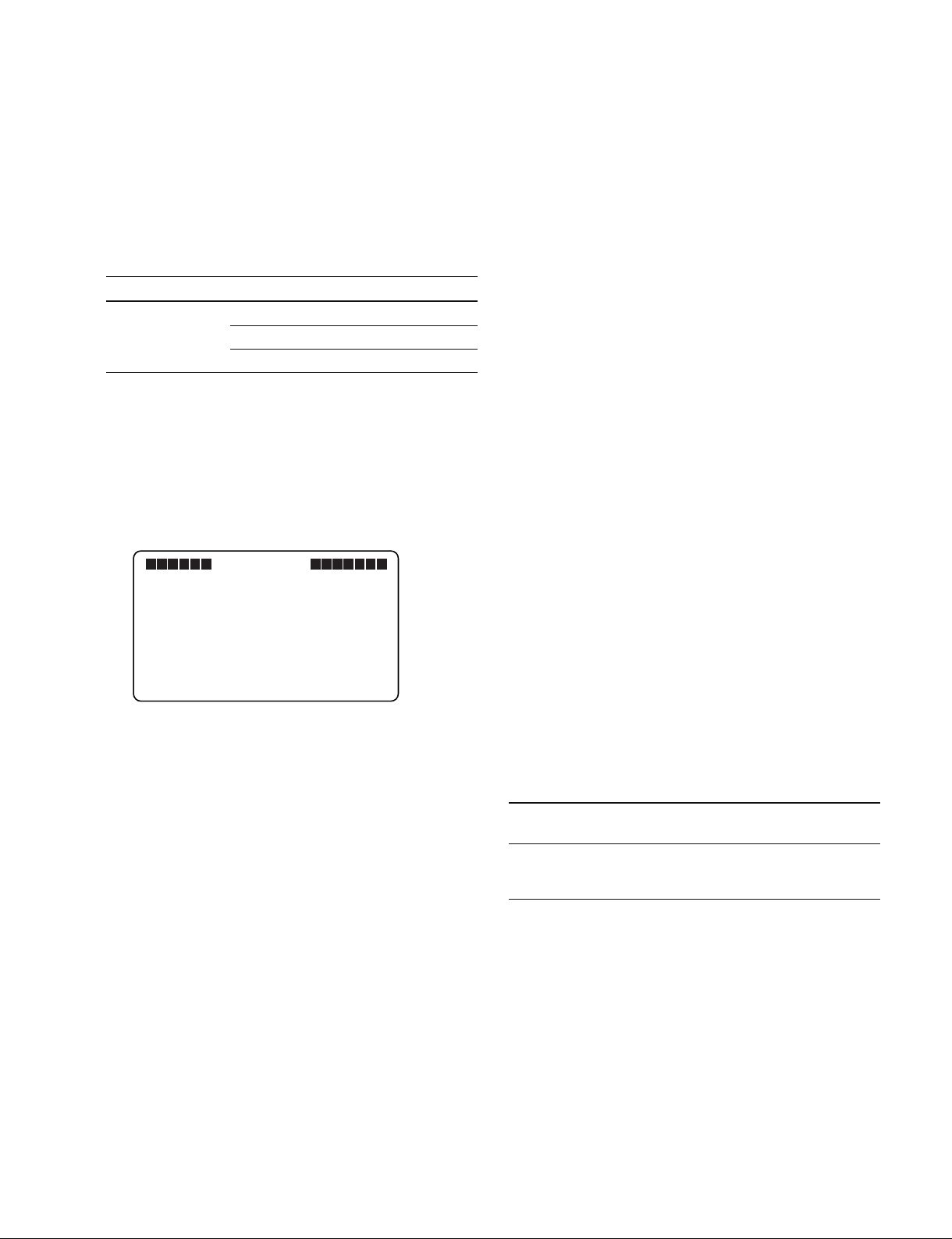
1-5-1. Checking the ROM and Software
Version
1. Display the TOP menu.
Refer to “2-2. TOP Menu”.
2. Display the VERSION screen in the SERVICE menu.
VF MENU
S08 VERSION
SOFTWARE
MAIN: 1.00
BOOT: 1.00
FPGA : 1.00
3. Check the ROM version.
1-5-2. Writing and Rewriting PLD Internal
Data
The device is equipped with a PLD (Programmable Logic
Device) that can be written and rewritten using the eProduction (EPR) method.
When replacing the following parts or upgrading the PLD
version, contact your local Sony Sales Office/Service
Center.
n
The part number of the PLD (or the ROM for the PLD)
noted in “Spare Parts” is for a part with no data written.
When you need to replace any part, write data using the
steps on the next page.
For a PLD that has a program operating on the externally
connected ROM, when a part in the PLD is defective, if
you replace only the defective part, you do not have to
rewrite the data.
About e-Production
. When writing or rewriting the PLD internal data,
1. Standard tools (cables) can be used.
2. Standard software (PLD Download Tool) can be
used.
. The PLD internal data is managed on the Sony database
server as a Project file (E_xxx_xxx_xx_xx).
. The standard connector (EPR connector) for writing
PLD internal data on the board is equipped. “EPR” is
displayed on the board.
HDVF-C950W
Corresponding PLDs :
Name of board
PLD/ROM EPR connector Project file No.
PR-292
IC305*1, IC314*1,
IC300 CN14 E_000_003_61_01
*1 : IC305 and IC314/PR-292 are the ROMs for IC300/PR-292.
1-5 (E)

Used equipment
. PLD download tool (Sony part No. : J-7120-140-A)
Cable to connect PC and the device
. PC
Computer with a parallel port.
Computer with PLD Download Tool installed.
For the supported OS and operating environment, refer
to “Download Tool Operation Manual (Device Writing
Volume)”.
Operation procedure
The procedure to write data to the PLD (or the ROM for
the PLD) is outlined below.
For details on these steps, refer to “Download Tool
Operation Manual (Device Writing Volume)”.
“Download Tool Operation Manual (Device Writing
Volume)” can be obtained on the same Web site where the
PLD Download Tool software is downloaded.
Step 1. Prepare the Project file.
n
Download the Project file from the Sony database
server.
Step 2. With the power of the device turned off, connect
the parallel port on the PC and the EPR connector
on the target board with the PLD download tool
(cable).
Step 3. Turn on the power of the device.
Launch the PLD Download Tool software, and
import the Project file.
Step 4. Program the PLD (or the ROM for the PLD) by
using the PLD Download Tool software.
Step 5. When the programming completes correctly
(without an error message), restart the device.
1-6 (E)
HDVF-C950W
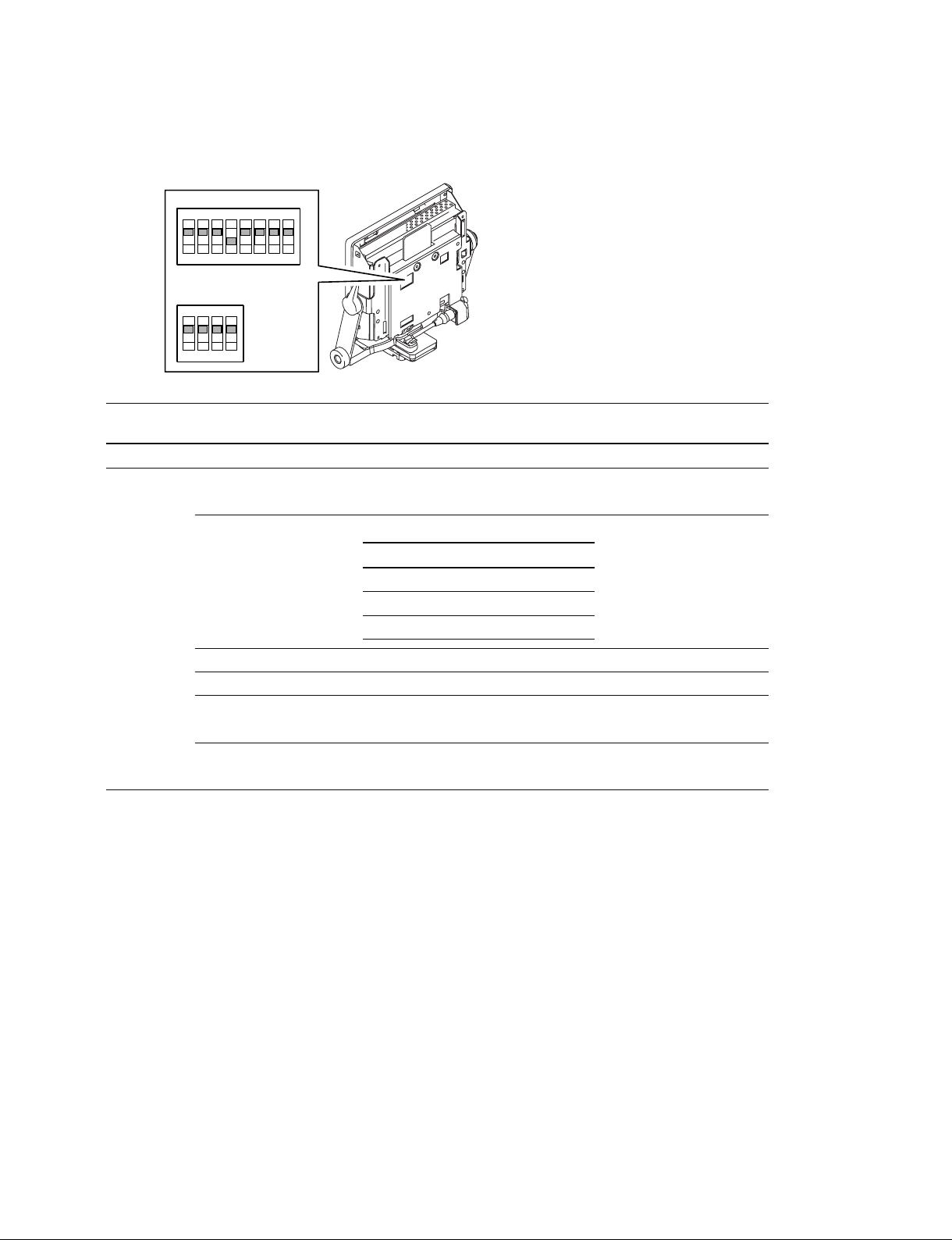
1-6. Description of On-board Switches
PR-292 board
8
4
7
S600
3
S601
6
2
N
2
1
3
4
5
O
N
1
O
Ref. No. Name Bit Contents Factory default
setting
S600 Model ID 1 to 4 All OFF
S601 SECOND VF settings 1 OFF: Normal OFF
ON : When used as the Second VF
Input signal format 2 to 4 All OFF
*2
settings
AUTO 60i 50i 24PsF
*1
2 OFF ON OFF ON
3 OFF OFF ON ON
4 OFF OFF OFF OFF
5ON
6 OFF
BOOT SOFT VERSION UP 7 OFF : Normal OFF
ON : During VERSION UP
MAIN SOFT VERSION UP 8 OFF: Normal OFF
ON : During VERSION UP
*1 : Set this to ON only when using the device as the second VF by connecting it to the EXT I/O (20P) connector of HDC-950 or HDC-
930. (No setting change is required when using the device alone.)
In this case, a dedicated VF connection cable and the corresponding camera settings are needed.
Contact your nearest SONY Office/Service Center for details.
No setting change is required when connecting the device to the EXT I/O (20P) connector of HDC-F950.
*2 : The input signal format must be set according to the connected camera. Change the setting only when you want to fix the format on
the VF side.
HDVF-C950W
1-7 (E)
1-7. Removal/Installation of Main Parts
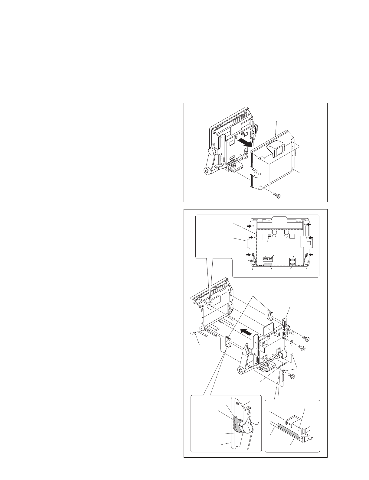
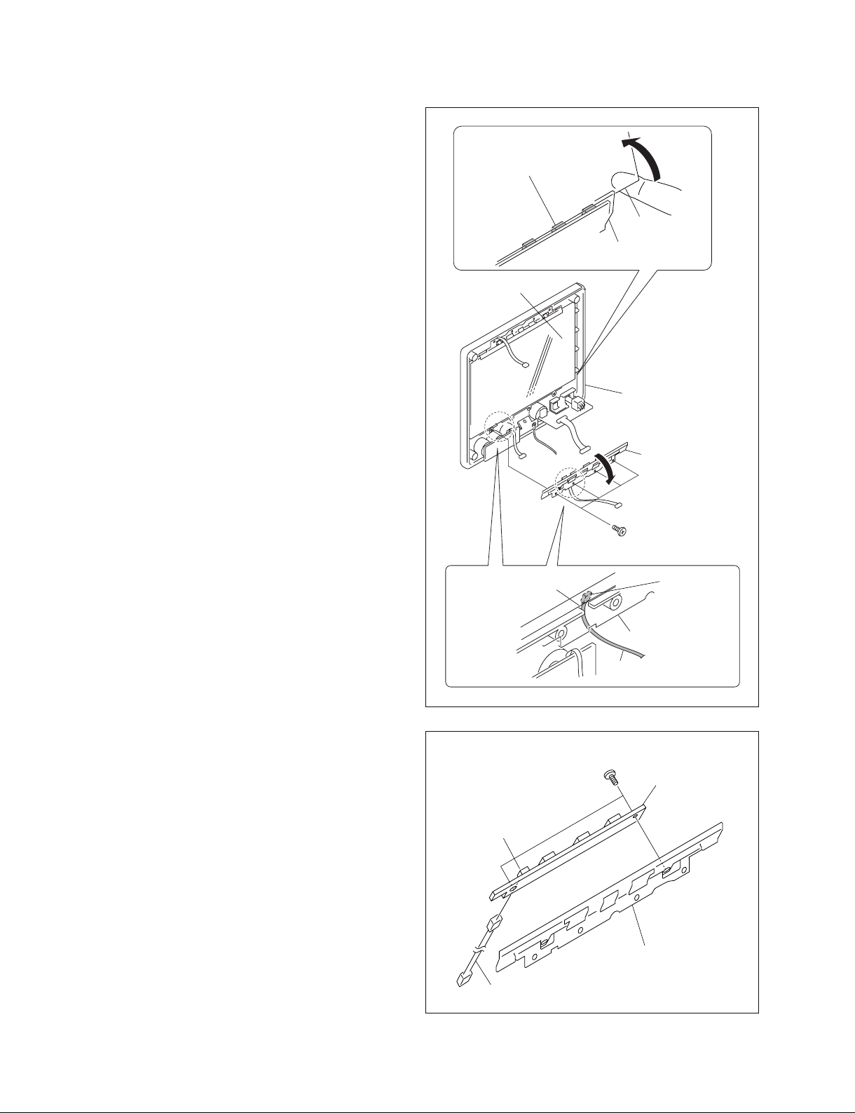
1-7-1. Removing LCD Module
n
When installing the dustproof cushions, install new
dustproof cushions.
Dustproof cushions (H), (V), conductive fabric tape
1. Remove the four screws and remove the rear cover
assembly.
2. Disconnect the six harnesses from the connectors
(CN5, CN6, CN8, CN9, CN11 and CN12) of the PR292 board.
3. Remove the two screws and remove the two GND
terminals from the CN box bracket.
n
When installing the GND terminals, install them in the
remote location from the hole “A” with the terminal
facing inside.
4. Peel the conductive fabric tape at the bottom of the CN
box bracket.
Precautions for installation
. Affix the conductive fabric tape before connecting
the harness.
. Affix the conductive fabric tape to the CN box
bracket and the EMC cover after installing the CN
box bracket to the bezel assembly.
PR-292 board
CN box bracket
Bezel
assembly
CN9
Hole
“A”
GND terminal
Tilt shaft covers
Rear cover assembly
B3 x 8
CN12
CN11
CN8
CN5
Hole “A”
CN6
CN box bracket
B2.6 x 5
B2.6 x 5
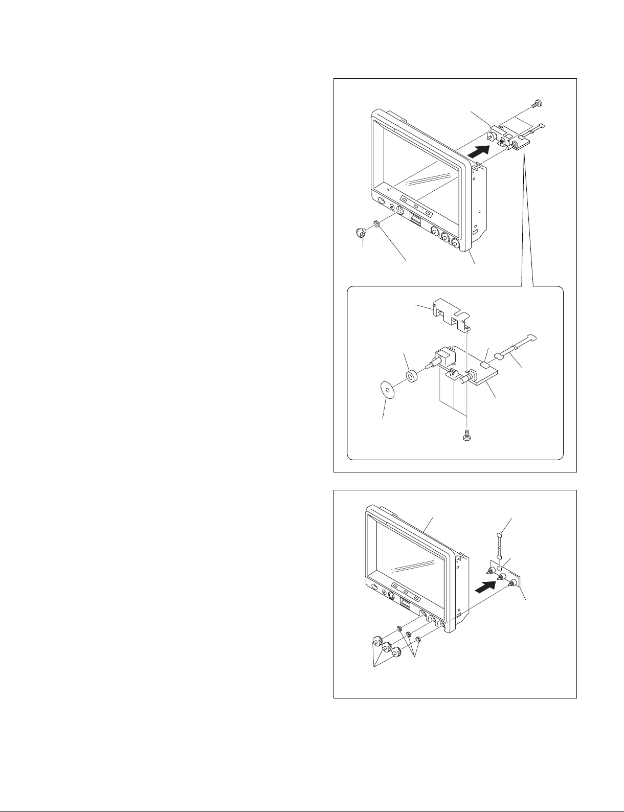
5. Remove the four screws and remove the bezel assembly from the CN box bracket.
m
. When the CN box bracket is removed from the bezel
assembly, the tilt shaft covers are removed. Be
careful not to drop them.
. When installing the bezel assembly to the CN box
bracket, install the bezel assembly to the CN box
bracket first of all. Then, connect the harnesses.
6. Remove the right and left tilt shaft covers from the
groove of the bezel cover assembly.
1-8 (E)
Groove
Tilt shaft
cover
Tilt stand
assembly
Bezel
assembly
Conductive fabric tape
EMC cover
GND
terminals
B2.6 x 5
CN box bracket
Conductive fabric tape
HDVF-C950W
Harness (BL)
Harness (LVDS)
CN1
P1
LCD bracket (L)
Shield cushion
LCD module
LCD bracket (R)
B2.6 x 5
B2.6 x 5
LCD bracket (L)
LCD unit
B2.6 x 5
B2.6 x 5
EMC cover
EMC cover
GND terminal
Dustproof cushions (V)
Dustproof
cushions (H)
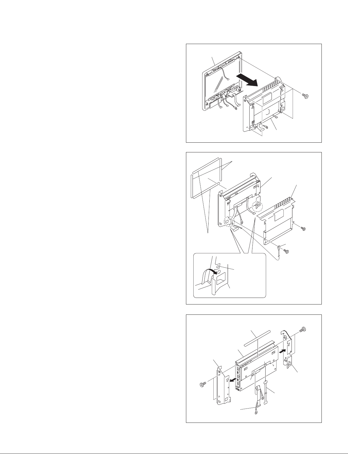
7. Remove the four screws and remove the LCD unit.
n
Standard tightening torque :
_2
25 x 10
N.m (2.5 kg.cm)
8. Remove the two screws and remove the GND terminal
and the EMC cover in the direction of arrow.
9. Remove the two dustproof cushions (V) and the two
dustproof cushions (H) from the front of the LCD
panel.
Bezel assembly
B2.6 x 5
LCD unit
10. Remove the four screws and remove the LCD brackets
(L) / (R).
11. Disconnect the harnesses from the two connectors
(CN1, P1) of the LCD module, and remove the shield
cushion.
12. Reinstall it by reversing the steps 1 to 11 of disassembling.
n
When the LCD module is replaced, the adjustment is
required. Refer to “Section 3. Electrical Adjustment”.
HDVF-C950W
1-9 (E)
1-7-2. Removing the LE-317 Board
PR-292 board
1. Remove the rear cover assembly.
(Refer to Section 1-7-1 step 1.)
2. Remove the bezel assembly.
(Refer to Section 1-7-1 steps 2 to 5.)
3. Remove the two screws and remove the LE-317 board
from the board-to-board connector of the PR-292
board.
4. Reinstall it by reversing the steps 1 to 3 of disassembling.
1-7-3. Removing the PR-292 Board
1. Remove the rear cover assembly.
(Refer to Section 1-7-1 step 1.)
2. Remove the bezel assembly.
(Refer to Section 1-7-1 steps 2 to 5.)
3. Remove the LE-317 board.
(Refer to Section 1-7-2 step 3.)
4. Remove the screw and remove the GND terminal.
5. Disconnect the harness from the connector (CN1) of
the PR-292 board.
6. Disconnect the two harnesses from the connectors
(CN2, CN10) of the PR-292 board.
n
Disconnect the harness (VF) on the connector (CN2)
side of the PR-292 board toward the front side of the
main unit through the CN box bracket A hole.
LE-317 board
PSW3 x 6
To the front of
the main unit
GND terminal
PSW3 x 6
PSW3 x 6
PSW3 x 6
Board-to-board
Harness (VF)
Harness (VF)
Dowel for LE-317 board
PR-292 board
CN2
CN box bracket
A hole
CN1
Dowel for
PR-292 board
7. Remove the two screws and remove the PR-292 board.
8. Remove the three screws (PS2.5 x 5), and remove the
RE-237 board.
n
When installing the RE-237 board, apply the screw
locking compound.
9. Reinstall it by reversing the steps 1 to 8 of disassembling.
1-10 (E)
PS2.5 x 5
RE-237 board
To the rear of
the main unit
Harness (SW1)
CN box bracket
A hole
Board-to-board
CN10
CN2
PR-292 board
Claws
PR-292 board
SW-1299 board
Harness (VF)
HDVF-C950W
Board-to-board
PR-292 board
RE-237 board
PS2.5 x 5
1-7-4. Removing the RE-237 Board
1. Remove the rear cover assembly.
(Refer to Section 1-7-1 step 1.)
2. Remove the bezel assembly.
(Refer to Section 1-7-1 steps 2 to 5.)
3. Remove the three screws and remove the RE-237
board.
n
When installing the RE-237 board, apply the screw
locking compound to the screws.
4. Reinstall it by reversing the steps 1 to 3 of disassembling.
1-7-5. Removing the LE-315 Board
1. Remove the rear cover assembly.
(Refer to Section 1-7-1 step 1.)
2. Remove the LCD unit.
(Refer to Section 1-7-1 steps 2 to 7.)
3. Remove the four screws and remove the LED bracket
and the LE-315 board from the bezel assembly in the
direction of arrow.
m
. To install the LED bracket and the LE-315 board to
the bezel assembly, pass the harness (LE) through
the cut-out for the harness (LE).
Be careful not to pinch the harness (LE) with the
LED bracket.
. Do not scar the protection panel.
Cut-out for the harness (LE)
LED bracket
Harness (LE)
LE-315 board
(CN1)
BTP2.6 x 6
n
Standard tightening torque :
25 x 10_2 N.m (2.5 kg.cm)
4. Disconnect the harness from the connector (CN1) of
the LE-315 board.
5. Remove the two screws and remove the LED bracket
from the LE-315 board.
6. Reinstall it by reversing the steps 1 to 5 of disassembling.
HDVF-C950W
LED bracket,
LE-315 board
Bezel assembly
LED bracket
Harness (LE)
LE-315 board
B2.6 x 5
1-11 (E)
1-7-6. Removing the LE-316 Board
1. Remove the rear cover assembly.
(Refer to Section 1-7-1 step 1.)
2. Remove the bezel assembly.
(Refer to Section 1-7-1 steps 2 to 5.)
3. Remove the four screws. Raise the protection panel in
the direction of arrow A, and remove the LED bracket
and the LE-316 board in the direction of arrow B.
m
. To install the LED bracket and the LE-316 board in
the bezel assembly, pass the harness (LE) through
the cut-out for the harness (LE).
Be careful not to pinch the harness (LE) with the
LED bracket.
. Do not scar the protection panel.
n
Standard tightening torque :
25 x 10_2 N.m (2.5 kg.cm)
LE-316 board
Protection panel
A
Protection panel
LED bracket
Bezel assembly
B
BTP2.6 x 6
LED bracket,
LE-316 board
4. Disconnect the harness from the connector (CN1) of
the LE-316 board.
5. Remove the two screws and remove the LED bracket
from the LE-316 board.
6. Reinstall it by reversing the steps 1 to 5 of disassembling.
Cut-out for the
harness (LE)
CN1
Harness (LE)
LE-316 board
(CN1)
LED bracket
Harness (LE)
B2.6 x 5
LE-316 board
LED bracket
1-12 (E)
HDVF-C950W
BTP2.6 x 6
B2.6 x 5
SW-1298 board
CN1
Bezel assembly
SW bracket
RE knob
Hexagon nut
Splash-proof cushion
Splash-proof rubber
Harness
SW-1298 board,
SW bracket
1-7-7. Removing the SW-1298 Board
1. Remove the rear cover assembly.
(Refer to Section 1-7-1 step 1.)
2. Remove the bezel assembly.
(Refer to Section 1-7-1 steps 2 to 5.)
3. Remove the RE knob and the hexagon nut from the
bezel assembly.
n
Do not scar the front panel.
4. Remove the two screws (BTP2.6 x 6), and remove the
SW bracket and the SW-1298 board.
5. Remove the three screws (B2.6 x 5), and remove the
splash-proof rubber, the splash-proof cushion and the
SW bracket from the SW-1298 board.
6. Disconnect the harness from the connector (CN1) of
the SW-1298 board
7. Reinstall it by reversing the steps 1 to 6 of disassembling.
1-7-8. Removing the VR-315 Board
1. Remove the rear cover assembly.
(Refer to Section 1-7-1 step 1.)
2. Remove the bezel assembly.
(Refer to Section 1-7-1 steps 2 to 5.)
3. Remove the three VR control knobs from the bezel
assembly.
4. Remove the three VR nuts M6 and remove the VR-
5. Disconnect the harness from the connector (CN1) of
6. Reinstall it by reversing the steps 1 to 5 of disassem-
315 board.
n
Do not scar the front panel.
the VR-315 board.
bling.
VR control knob
Bezel assembly
VR nut M6
Harness (VR)
CN1
VR-315 board
HDVF-C950W
1-13 (E)
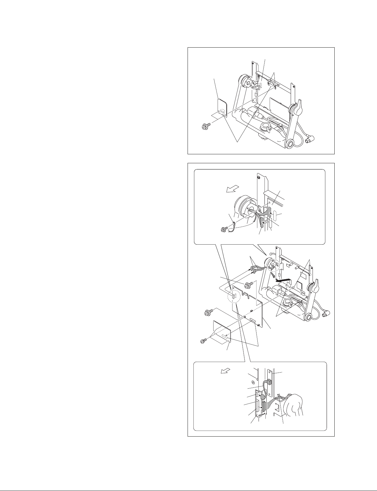
1-7-9. Removing the Harness (VF)
1. Remove the rear cover assembly.
(Refer to Section 1-7-1 step 1.)
2. Remove the bezel assembly.
(Refer to Section 1-7-1 steps 2 to 5.)
3. Remove the screw and remove the GND terminal.
(Refer to Section 1-7-3 step 4.)
4. Disconnect the harness from the connector (CN1) of
the PR-292 board. (Refer to Section 1-7-3 step 5.)
5. Disconnect the harness from the connector (CN2) of
the PR-292 board and remove it toward the front of the
machine through the CN box bracket A hole.
(Refer to Section 1-7-3 step 6.)
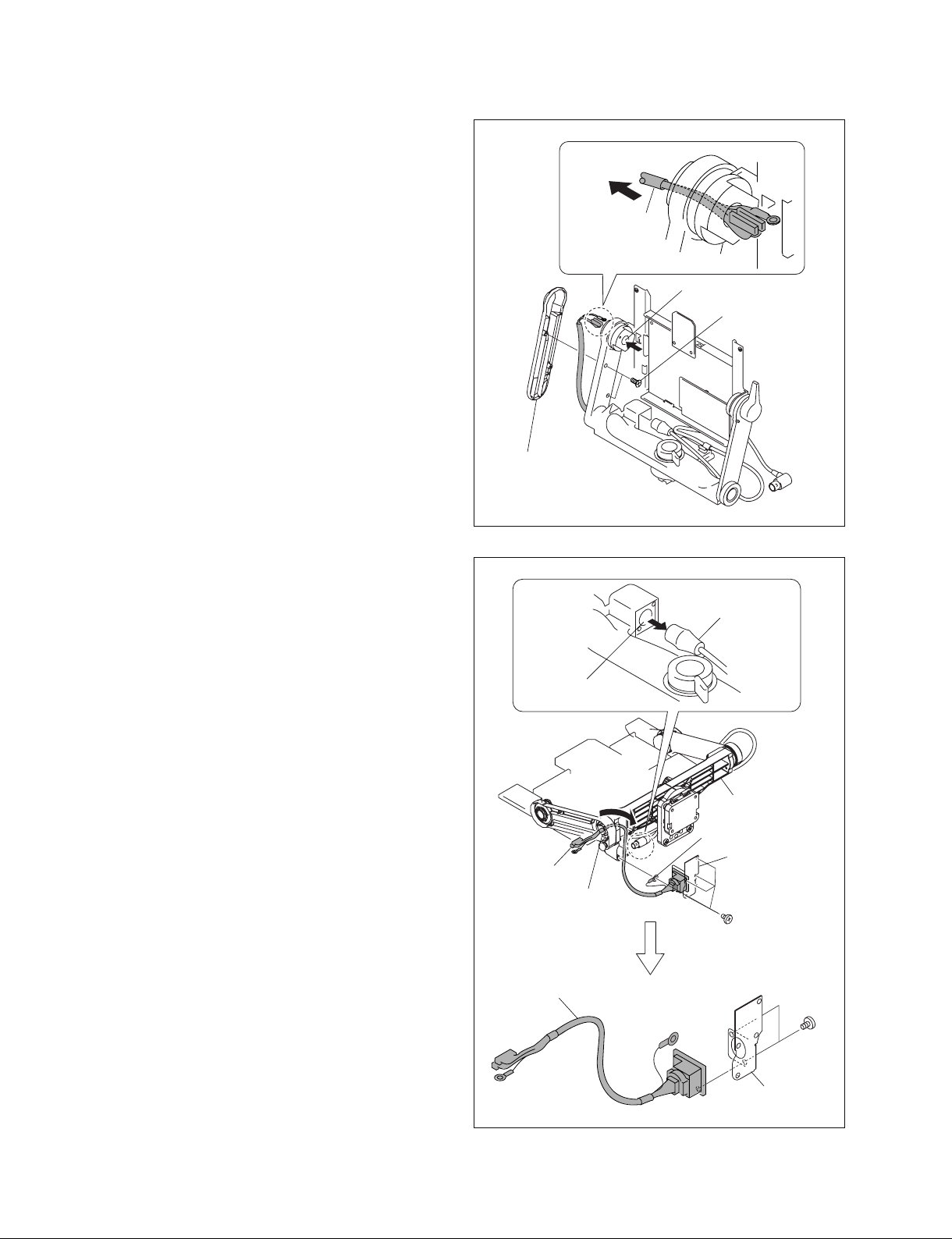
6. Remove the two screws and remove the arm cover (L).
7. Disconnect the harness through the tilt shaft (L) hole
in the direction of arrow.
n
Be careful not damage the harness (VF).
8. Disconnect the VF connection cable from the harness.
9. Remove the four screws (P2.6 x 5), and remove the
GND terminal, the bottom plate and harness from the
pan arm.
10. Remove the harness from the arm lift shaft in the
direction of arrow.
n
Be careful not damage the harness (VF).
Harness (VF)
Tilt shaft (L) hole
BTTP2.6 x 8
Arm cover (L)
VF connection cable
Harness (VF)
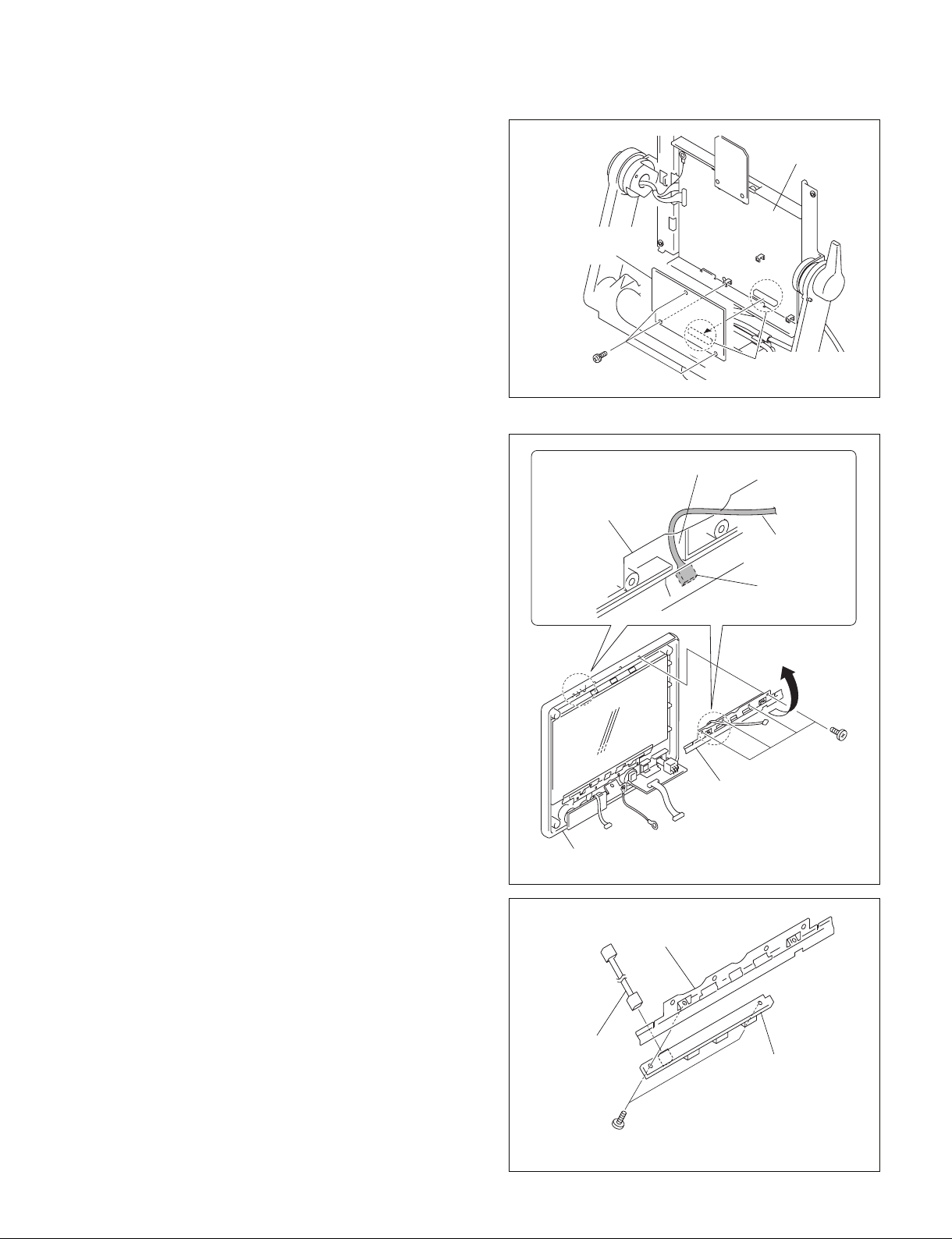
11. Remove the two screws (M2 x 5) and remove the
harness (VF) from the bottom plate.
12. Reinstall it by reversing the steps 1 to 11 of disassembling.
1-14 (E)
Harness (VF)
Arm lift shaft
Harness (VF)
Pan arm
GND terminal
Bottom plate,
harness (VF)
P2.6 x 5
M2 x 5
Bottom plate
HDVF-C950W

1-8. Extending the Circuit Board
B3 x 8
PR-292
board
PR/RE extension
assembly
RE-237 board
EX-1018 board
EX-1017 board
CN1
CN4
Fixture required: PR/RE extension assembly
n
Life of flexible card wire will be significantly shortened if
it is folded. Be very careful not to fold the flexible card
wire.
1-8-1. Service Position
1. Remove the rear cover assembly.
(Refer to Section 1-7-1 step 1.)
2. Disconnect the two harnesses from the connectors
(CN11, CN12) of the PR-292 board. (Refer to Section
1-7-1 step 2.)
3. Remove the bezel assembly.
(Refer to Section 1-7-1 steps 3 to 5.)
4. Insert the claws of the CN box bracket (L)/(R) into the
grooves (L)/(R) of the LCD bracket as shown in the
figure.
1-8-2. RE-237 Board
Groove of the LCD bracket (L)
Claws of the CN box
bracket (L)/(R)
Groove of the LCD
bracket (R)
Groove of the LCD
bracket (L)/(R)
1. Set the unit to the service position.
(Refer to Section 1-8-1.)
2. Remove the RE-237 board.
(Refer to Section 1-7-4 step 3.)
3. Connect the PR/RE extension assembly (EX-1017
board side) to the connector (CN4) of the PR-292
board.
4. Install the PR/RE extension assembly (EX-1018 board
side) with the screw to the CN box bracket.
n
Fix the EX-1018 board to the position shown in the
figure with the screw (B3 x 8) removed from the rear
cover.
5. Connect the RE-237 board to the connector of the PR/
RE extension assembly (EX-1018 board side).
HDVF-C950W
1-15 (E)

1-9. Fuse and IC Link Replacement
1-10. Unleaded Solder
w
The fuse and IC link are critical parts to safe operation.
Replace the components with Sony parts whose part
number appear in the manual published by Sony. If the
components are replaced by any parts other than the
specified ones, this may cause a fire or electric shock.
c
If a fuse or IC link is replaced while the main power is kept
on, this may cause electric shock.
Before replacing fuse or IC link, not only turn off the
POWER switch but also remove the power cable that is
connected to the DC IN connector.
The RE-237 board is equipped with fuse. The PR-292
board is equipped with IC link.
Any an excessive current flow due to abnormality inside
the equipment, the fuse and IC link blow. If a fuse or IC
link blows, turn off the main power of the equipment once
and inspect inside of the equipment and remove the cause
of excessive current. After that, replace the fuse and/or IC
link.
Boards requiring use of unleaded solder are printed with a
lead free mark (LF) indicating the solder contains no lead.
(Caution: Some printed circuit boards may not come
printed with the lead free mark due to their particular size.)
: LEAD FREE MARK
m
. Be sure to use the unleaded solder for the printed circuit
board printed with the lead free mark.
. The unleaded solder melts at a temperature about 40 dC
higher than the ordinary solder, therefore, it is recommended to use the soldering iron having a temperature
regulator.
. The ordinary soldering iron can be used but the iron tip
has to be applied to the solder joint for a slightly longer
time. The printed pattern (copper foil) may peel away if
the heated tip is applied for too long, so be careful.
Board Ref. No. Description Part No.
RE-237 F1 Fuse !1-576-269-21
(3.15 A/125 V)
PR-292 PS1, 2, 3, 4 IC link 0.6 A !1-576-259-21
1-16 (E)
HDVF-C950W
Section 2
MENU
POWER
ONOFF
Setting Menu
2-1. Setting Menu
The setting menu is used for selecting and adjusting all of
the parameters.
Setting menu configuration
The Setting menu consists of the following menus.
. OPERATION menu
. SERVICE menu
n
The TOP menu screen is also available for displaying the
entire configuration of the menu items.
For information about how to display the TOP menu, refer
to “2-2. TOP Menu”.
Description of switches
MENU knob
Selects items in the menu or changes the parameters.
Turn : Move to the next item or page and change parame-
ters.
Press : Select the next item or page and set parameters.
MENU switch
Displays the setting menu.
Deletes changed parameters during setting and returns to
page selection mode or the TOP menu.
PEAKING BRIGHT
CONTRAST
MENU switch
POWER
MENU
ONOFF
MENU knob
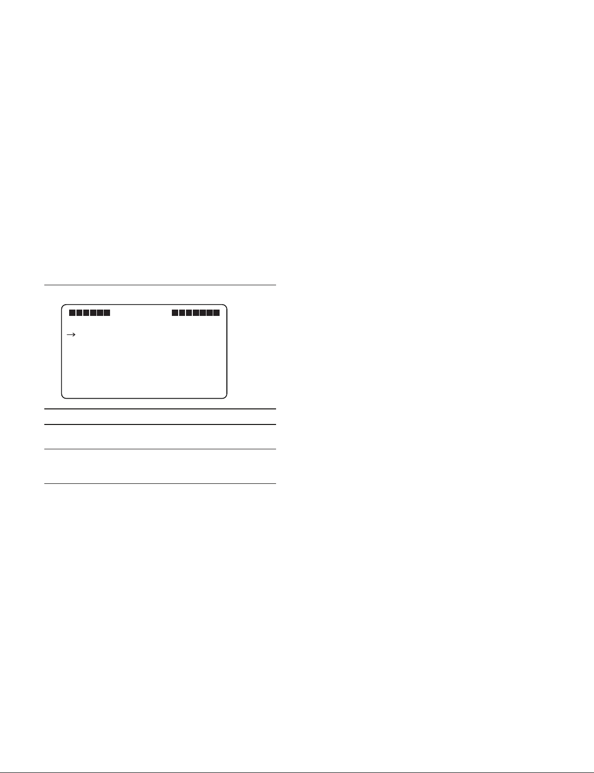
Basic operations
1. Display the menu
Press the MENU switch to display the OPERATION menu.
2. Select the menu page
With the “?” mark displayed in front of the page
number (page selection mode), turn the MENU knob.
When the desired page is displayed, press the MENU
knob.
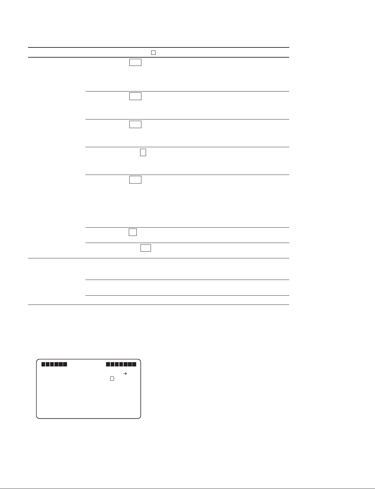
3. Select the item
With the cursor mark “→” display in front of the setting
items in the selected page (item selection mode), turn the
MENU knob. When the cursor mark “→” lines up with
the item you want to change, press the MENU knob.
4. Change the parameter
With the “?” mark displayed in front of the parameter (parameter changing mode), turn the MENU
knob to change the parameter.
If the parameter is a number, turning the MENU
knob clockwise increases the value and turning it
counter-clockwise decreases the value.
Turning the knob far increases the value quickly,
while slowly turning the knob fine-tunes the value.
5. Set the parameter
Press the MENU knob.
This sets the parameter and returns to item selection
mode.
n
If the MENU switch it pressed before pressing the
MENU knob, the parameter returns to the value
before making changes and the screen returns to
item selection mode.
6. Exit the menu display
Every time the MENU switch is pressed, a different
operation is performed. First, the screen switches to
item selection mode, then page selection mode, then
returns to the TOP menu*1.
Pressing the MENU switch a final time exits menu
display.
HDVF-C950W
7. Return the parameters to the defaults
Move the cursor mark “→” in front of the parameter that you want to return to default. Press and hold
the MENU knob for two or more seconds.
*1 : Only has to be performed when operating from the TOP menu.
Refer to “2-2. TOP Menu”.
2-1 (E)
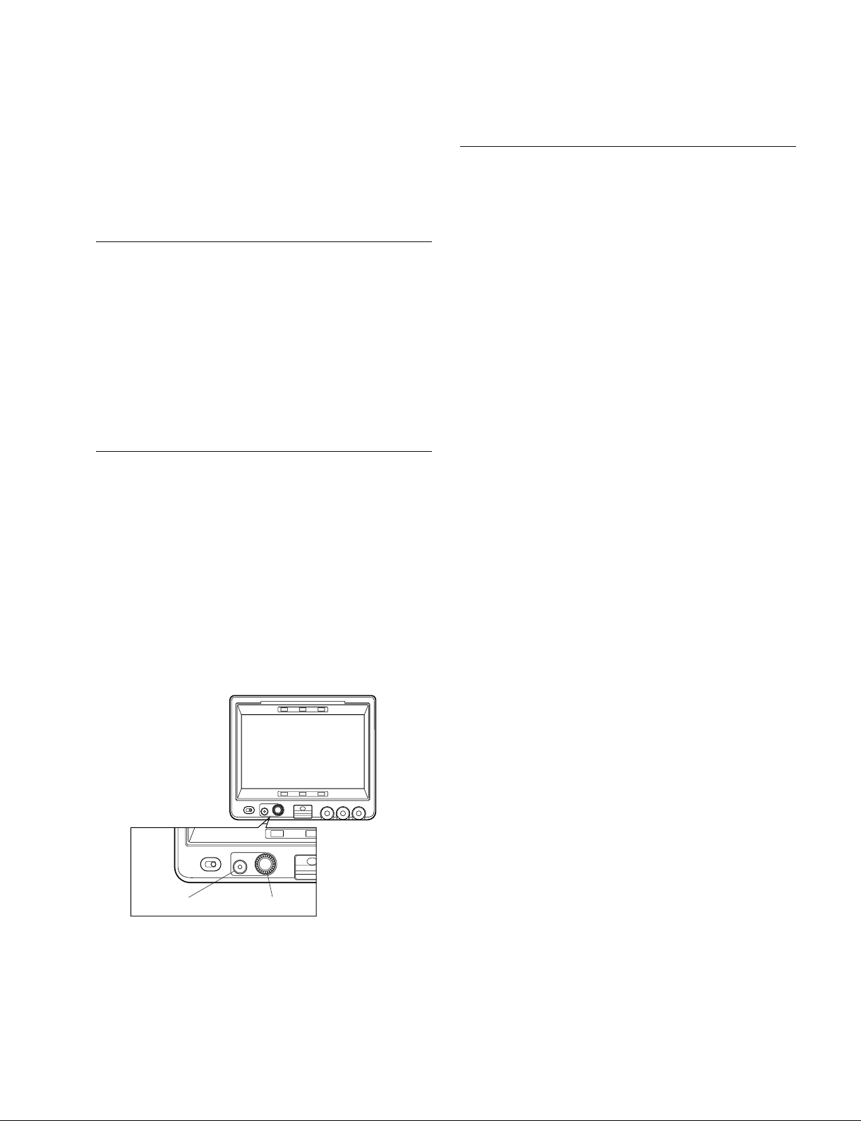
2-2. TOP Menu
The TOP menu displays all of the menu items.
Displaying the TOP Menu
1. Set the control knob on the front to the following
settings.
1 CONTRAST knob : 99 (Turned fully clockwise)
2 BRIGHT knob : _99 (Turned fully counter-
clockwise)
3 PEAKING knob : 100 (Turned fully clockwise)
2. Press the MENU switch while holding down the
MENU knob.
The TOP menu is displayed.
TOP MENU screen
VF MENU
<TOP MENU>
OPERATION
SERVICE
Menu items Contents
OPERATION Contains the setting items required when the
SERVICE Contains items required for maintaining the
camera operator is using the device.
View Finder, such as electrical alignment,
HOURS METER, and self-diagnosis function.
2-2 (E)
HDVF-C950W
2-3. OPERATION Menu
The OPERATION menu contains the setting items required when the camera operator is using the device.
For more information, refer to the operation manual that comes with this device.
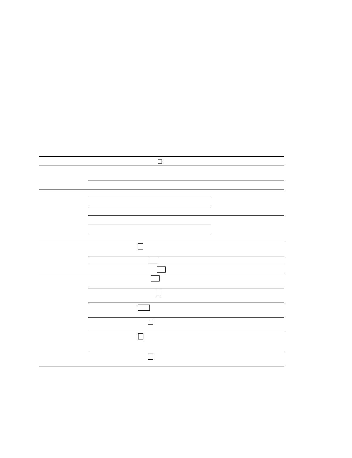
2-4. SERVICE Menu
The SERVICE menu contains items required for maintaining the View Finder, such as electrical alignment, HOURS METER, and self-diagnosis function.
m
. The next menu item may not be selectable depending on the current menu item setting.
. “___” is displayed as the parameter for unselectable items.
Page Menu Items Setting ( indicates the default) Function
S01*1ADJUST INVERTER POWER 0 to 215 Adjusts the inverter power
supply voltage
BL DIMMER 0 to 255 Adjusts the backlight
S02*1COLOR ADJUST BIAS R _512 to 511 Adjusts the black level color
TEMP
S03 GAMMA/ GAMMA SELECT 1 to 7 Switches the gamma table
KNEE Currently, only 1 is valid
S04 PEAKING FREQUENCY L, M, MH , H Sets the center frequency of the
*1 : The items of S01 and S02 are adjusted when shipped from the factory.
For information about adjustment, refer to Section 3 “Electrical Alignment”.
ADJUST BIAS G _512 to 511
ADJUST BIAS B _512 to 511
ADJUST GAIN R 0 to 255 Adjusts the white level color
ADJUST GAIN G 0 to 255
ADJUST GAIN B 0 to 255
KNEE POINT 0 to 213 to 255 Sets the knee point level
KNEE SLOPE 1/2, 1/3, 1/4 , CLIP Sets the knee slope level
SOURCE NAMY, Y , R, G, B Sets the video signal that makes
B MIX GAIN 0 dB , _6 dB, _12 dB, _18 dB Sets the mix gain that mixes the
CRUMPLE 0 to 1 to 3 Sets the bit shift for crumpling
RGB MIX R , G, B, CY, MG, YL, Sets the mix gain for R ch, G ch,
SKIN, SKY, FOIL, ORAN and B ch when mixing the
CRISPENING 0 to 5 to 63 Sets the level for crispening the
temperature
temperature.
peaking signal
the peaking signal
peaking signal to the B ch
the peaking signal
peaking signal to the main signal
peaking signal
HDVF-C950W
2-3 (E)
Page Menu Items Setting ( indicates the default) Function
S05 FUNCTION2 SECOND VF OFF , ON Switches the IIC address used as
the second VF
OFF : Normal
ON : When used as the second
VF
*1
PANEL REV <H> OFF , ON Inverses the screen display
horizontally
OFF : Normal
ON : Inverses horizontally
PANEL REV <V> OFF , ON Inverses the screen display
vertically
OFF : Normal
ON : Inverses vertically
MAG REL TIME 1 to 5 to 10 Sets the time it takes to return
from the enlarged view to the
normal view when MAG AUTO
RELEASE is set to AUTO
TEST SIGNAL OFF , BARS, SAW, RAST Sets the internal test signal
*2
*3
OFF : Does not output the test
signal
BARS: Outputs a color bar signal
SAW : Outputs a saw-tooth wave
test signal
RAST : Outputs a rectangular test
signal
COLOR SELECT W , R, G, B, Y, C, M Selects a display color when a
rectangular test signal is selected
TEST LEVEL 0 to 255 Sets the signal level when a
rectangular test signal is selected
S06 HOURS METER RESET METER EXEC Resets the OPERATION time
Press the MENU knob to move to
the operation screen
*4
OPERATION Display only Displays the total power-on time
(resettable)
TOTAL Display only Displays the total power-on time
*1 : Set this to ON only when using the device as the second VF by connecting it to the EXT I/O (20P) connector of HDC-950 or HDC-
930. (No setting change is required when using the device alone.)
In this case, a dedicated VF connection cable and the corresponding camera settings are needed.
Contact your nearest SONY Office/Service Center for details.
No setting change is required when connecting the device to the EXT I/O (20P) connector of HDC-F950.
*2 : Refer to AUTO RELEASE of OPERATION MENU 03 MEGNIFICATION.
*3 : This parameter will always start in OFF when the power is turned on.
*4 : Place the cursor mark “→” on “EXEC” and press the MENU knob to move to the following operation screen.
Place the cursor mark “→” on “YES” and press the MENU knob to perform reset.
VF MENU
S06 HOURS METER
RESET OK? YES NO
RESET METER : EXEC
OPERATION : XXXXXXH
TOTAL : XXXXXXH
2-4 (E)
HDVF-C950W
 Loading...