

Page 1
HD ELECTRONIC VIEWFINDER
HDVF-C750W
HDVF-C700W
電気製品は、安全のための注意事項を守らないと、火災
警告
このオペレーションマニュアルには、事故を防ぐための重要な注意事項と製
品の取り扱いかたを示してあります。このオペレーションマニュアルをよく
お読みのうえ、製品を安全にお使いください。お読みになったあとは、いつ
でも見られるところに必ず保管してください。
OPERATION MANUAL
や人身事故になることがあり、危険です。
[Japanese/English]
1st Edition
Page 2
安全のために
電気製品はまちがった使い方をすると、火災や感電などにより死亡や大けが
など人身事故につながることがあり、危険です。
事故を防ぐために次のことを必ずお守りください。
安全のための注意事項を守る
2(J)ページの注意事項をよくお読みください。
定期点検を実施する
長期間安全に使用していただくために、定期点検を実施することをおすすめ
します。点検の内容や費用については、ソニーのサービス担当者または営業
担当者にご相談ください。
故障したら使用を中止する
ソニーのサービス担当者または営業担当者にご連絡ください。
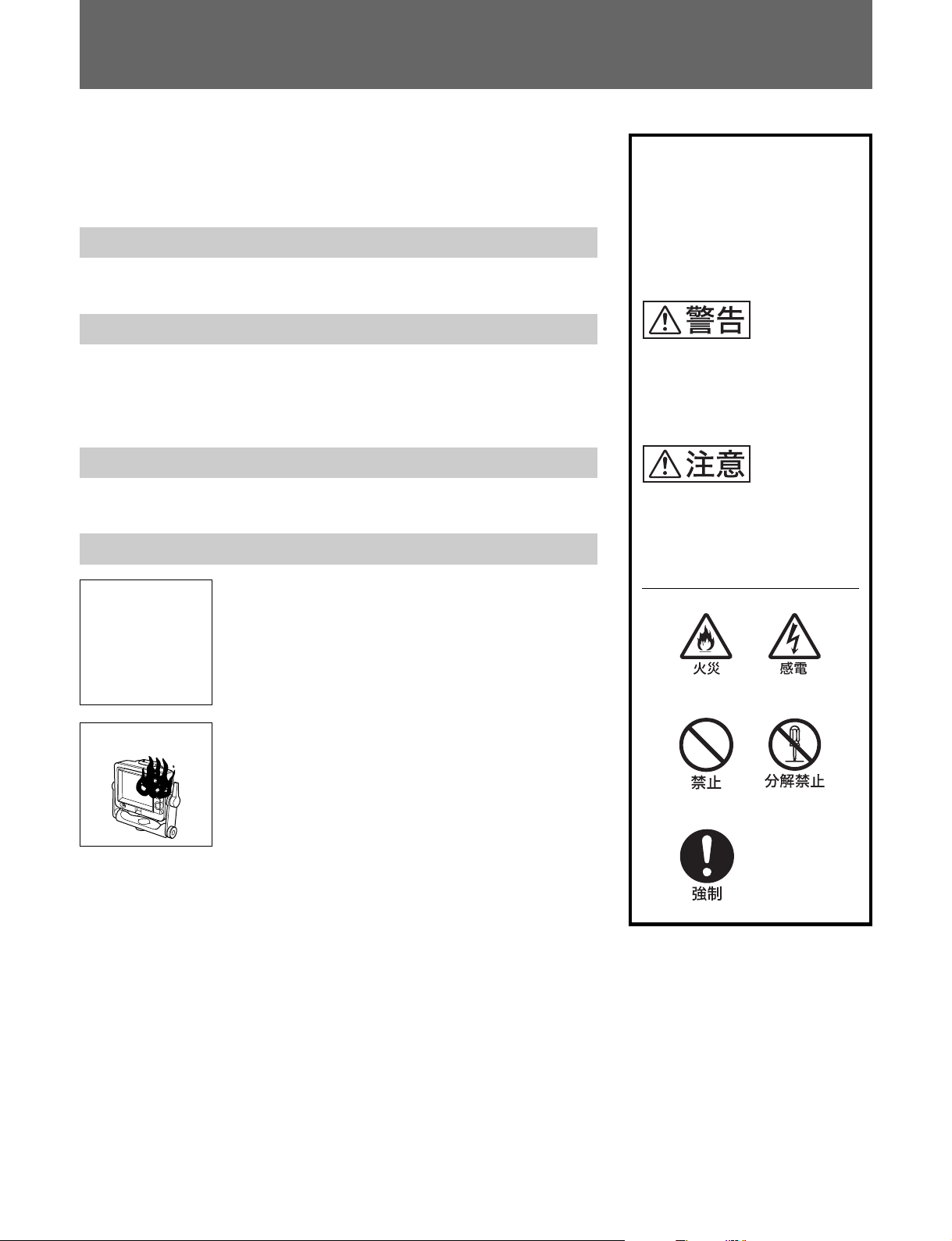
万一、異常が起きたら
1 カメラの電源を切る。
異常な音、
•
におい、煙
が出たら
落下させた
•
ら
,
2 接続コードを抜く。
3 ソニーのサービス担当者または営業担当者に修
理を依頼する。
警告・注意表示の意味
このオペレーションマニュアル
および製品では、次のような表
示をしています。表示の内容を
よく理解してから本文をお読み
ください。
この表示の注意事項を守らない
と、火災や感電などにより死亡
や大けがなど人身事故につなが
ることがあります。
この表示の注意事項を守らない
と、けがをしたり周辺の物品に
損害を与えることがあります。
注意を促す記号
行為を禁止する記号
炎が出たら
すぐにカメラの電源を切り、消火する。
,
行為を指示する記号
Page 3
目次
警告 ................................................................................................................
注意 ................................................................................................................
概要 .....................................................................................................................
使用上のご注意 ...................................................................................................
各部の名称と働き ...............................................................................................
カメラに取り付ける............................................................................................
HDVF-C750Wの場合 .......................................................................................... 6(J)
HDVF-C700Wの場合 .......................................................................................... 8(J)
位置を調節する ................................................................................................
高さ調整(HDVF-C750Wのみ) .........................................................................10(J)
チルティング操作..............................................................................................11(J)
パンニング操作(HDVF-C750Wのみ) .............................................................11(J)
画面を調整する ................................................................................................
アクセサリーを取り付ける ..............................................................................
フードを取り付ける.......................................................................................... 13(J)
ナンバープレートを取り付ける...................................................................... 14(J)
仕様 ..................................................................................................................
2(J)
2(J)
3(J)
3(J)
4(J)
6(J)
10(J)
12(J)
13(J)
15(J)
日
本
語
1(J)
Page 4
警告
下記の注意を守らないと、
感電火災
火災や感電 により死亡や大けがにつながることがあります。
分解しない、改造しない
分解したり、改造したりすると、感電の原因となります。
ビューファインダー内部の調整や点検を行う必要がある場合は、必ずソニー
のサービス担当者にご依頼ください。
内部に水や異物を入れない
水や異物が入ると火災の原因となります。
万一、水や異物が入ったときは、すぐにカメラの電源を切り、接続コードを
抜いて、ソニーのサービス担当者または営業担当者にご相談ください。
油煙、湯気、湿気、ほこりの多い場所では設置•使用しない
上記のような場所で設置・使用すると、火災や感電の原因となります。
下記の注意を守らないと、
けがをしたり周辺の物品に損害を与えることがあります。
ビューファインダーの取り付けは確実に行う
ビューファインダーは確実に固定してください。正しく取り付けられていな
いと、落下してけがの原因となることがあります。
ビューファインダーを取り外すときは、指示にしたがって行う
ビューファインダーの取り外しは、この説明書に記載されている方法で行っ
てください。正しく取り外さないと、落下してけがの原因となることがあり
ます。
三脚アタッチメントは重心を考慮して取り付ける
三脚アタッチメントを取り付けるときは、重心を考え、バランス良く取り付
けてください。
正しく取り付けられていないと、落下してけがの原因となることがありま
す。
2(J)
Page 5
概要
HDエレクトロニックビューファインダーHDVF-C750W/C700Wは、
ソニーハイビジ ョンカラ ーカメ ラ用の6型カ ラー ビューフ ァ インダーで
す。
本機には以下のような特長があります。
小型軽量
LCDの採用により、画面サイズが同等のCRTビューファインダーと
比べて小型軽量化を実現しています。
マルチスキャン
カメラからの制御信号により、これまでの60iに加えて、24PsFや
50iなどの各種フォーマットに対応します。
高解像度
高精細LCDを採用し、水平解像度500本以上の高解像度を実現
していま す。
タリーランプ
タリー信号によって 点灯する2系統(レッドおよびグリ ーン) のタ リーラ
ンプを備えています。
優れた操作性
HDVF-C750Wは高さを3段階に設定でき、上下両方向に90度ず
つ、左右両方向に90度ずつ角度を変えることができます。
HDVF-C700Wは上方向に90度、下方向に50度まで角度を変える
ことが できます。
防滴構造
多少の雨 にも耐えられる防滴構造 により、戸外での 撮影にも適して
います。
屋内フードおよび屋外フードを取り付け可能
堅牢で操作性のよい屋内フード(付属)と、遮光性に優れている屋
外フード(別売り)を取り付けるこ とができます。
安定した画像
LCDの採用により、画面の明るさに関係なく、ひずみのない安定
した画像が得られます。
ステップ可変ピーキング補正
ステップ可変ピーキング 補正回 路により、シャープな画像が得ら れ 、
カメ ラのピント合わせが容易です。
使用上のご注意
・本機の液晶パネルは非常に精密な技術で作られております。
まれに黒い画素が現れたり、常時点灯(赤、青、緑など)
する画素が存在することがありますが、故障ではありません
(有効画素99.99%以上)。
これらの現象はカメラの映像出力には影響しません。
省エネルギー設計
入力電圧の許容範囲が広く(10.5〜 17V)、しかも低消費電力
(10W)です。
・低温でのご使用時には、電源投入直後、動解像度が低下いたし
ます。
・画面 の表面からほこ りを取り除く ときは、ブロアーをお使いくださ
い。
・画面をクリーニングするときは、シ ンナー な どの溶剤はいっ さ い使
用しない でく ださい。
3(J)
Page 6
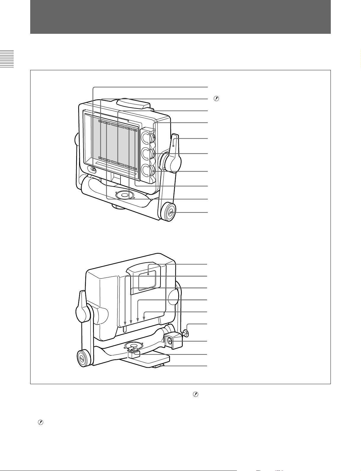
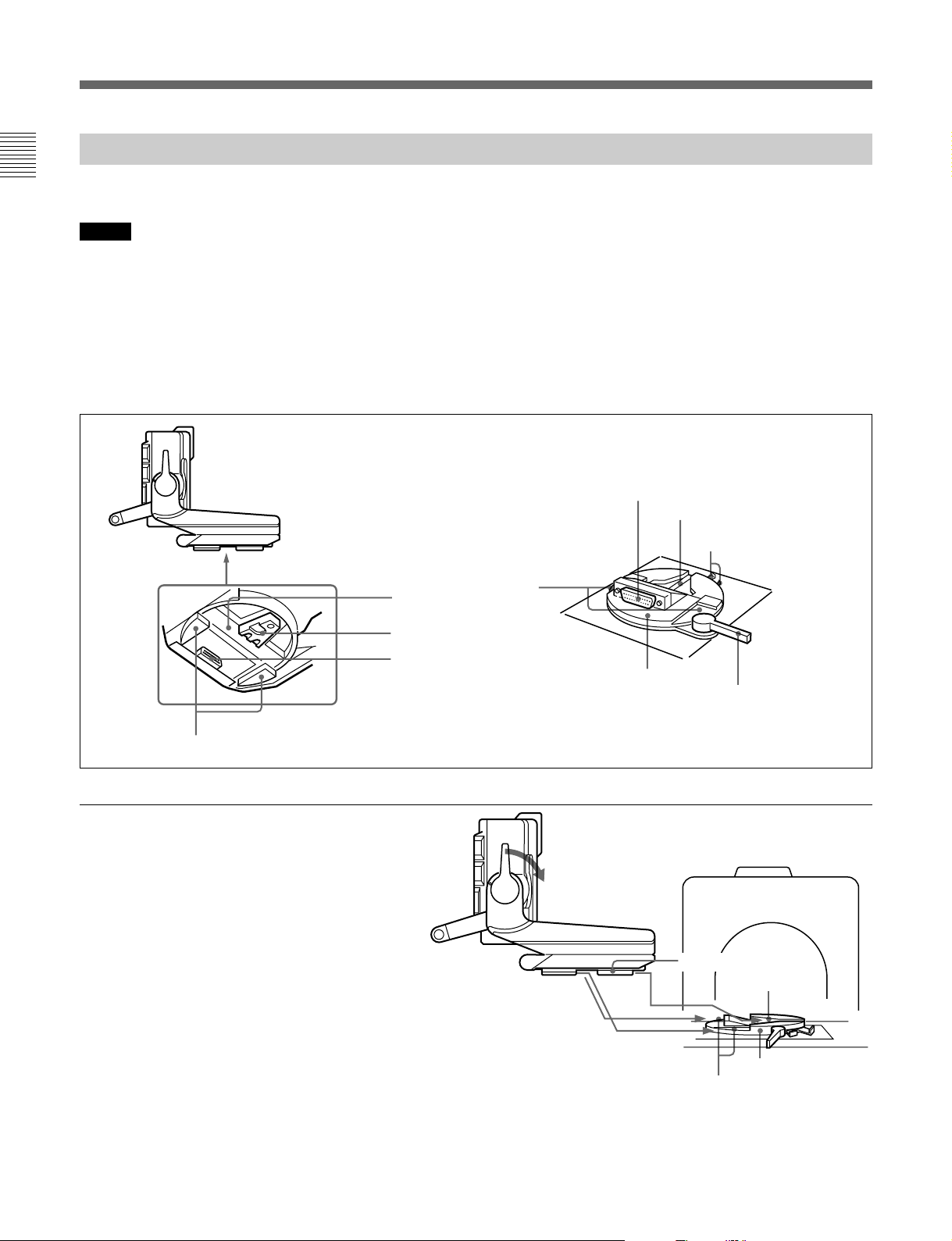
各部の名称と働き
図はHDVF-C750Wを示しています。
HDVF-C750WとHDVF-C700Wの各部の働きは、基本的には同じです。
前面
後面
1
POWER
2 (注意)ランプ
3 レッドタリーランプ
4
BRIGHT
5 フリクション調節/ロックレバー
6
CONTRAST
7
PEAKING
8
BATT
9 グリーンタリーランプ
q; リフトロック解除ノブ1
スイッチ
つまみ
つまみ
つまみ
(バッテリー)ランプ
1
POWER
(電源)スイッチ
カメラから本機への電源をON/OFFします。
2 (注意)ランプ
カメ ラがある特定 の状態になったとき点灯します。どの状態で点灯
させるかは、カメラで設定できます。
qa 外部タリーランプ
qs 外部タリー光量調節ボリューム
qd
TALLY ON/OFF
qf ブランキングマーカー
qg タリー光量調節スイッチ
qh リフトロック解除ノブ2
qj カメラ端子
qk クランパー
ql マウントウェッジ
◆ ランプが点灯する条件を設定/確認す る方法について は 、使用して
いるカメ ラのマニュアルをご覧く ださい。
スイッチ
ON/OFF
スイッチ
3 レッドタリーランプ
カメ ラにレッドタリー信号が供給されると点灯(赤)します。
4(J)
Page 7

4
BRIGHT
画面の明るさ(輝度)を調節します。
5 フリクション調節/ロックレバー
チルティング操作のフリクションを希望の度合いに調節します。
また、本機を希望の角度に固定するレバーです。レバーをカメラの
レンズ側 に倒すと固定さ れ 、手前に倒すとフリクション を調節できま
す。
6
CONTRAST
画面のコントラストを調節します。
7
PEAKING
画像の輪郭を補正できます。右に回すと補正量が多くなります。 調
節可能範囲はOFF〜16dBです。
8
BATT
カメ ラに 接続したバッテリ ーの電 圧が下がると点滅します。バッテ
リーが使用できなくなる と点灯します。
動作中断を防ぐため、バッテリーが点滅を開始した時点で、すば
やく バッテリ ーを交換してく ださい。
◆ 点滅を開始する電圧を、カメラ側で設定することができます。詳しく は、
使用しているカメ ラのマニュアルをご覧ください。
9 グリーンタリーランプ
カメラにグリーンタ リー信号が供給されると点灯(緑)します。
q; リフトロック解除ノブ1(
リフトロック解 除ノブ 2 qhと併用して、本機の高さを調節するとき使
用します。
◆操作方法については、「高さ調節(HDVF-C750Wのみ)」(10(J)ペー
ジ)をご覧く ださい。
(明るさ調節)つまみ
(コントラスト調節)つまみ
(ピーキング調節)つまみ
(バッテリー)ランプ
1)
1)
HDVF-C750W
1)
のみ)
qs 外部タリー光量調節ボリューム
調整用ドライバーなどを差し込んで光量を調節できます 。左方向に
回すと明る く なり、右方向に回すと暗くなります。
qd
TALLY ON/OFF
外部タリーランプ qaをコントロールします。
:タリーランプが機能する。
ON
:タリーランプが 機 能しな い(レッ ドタリー信 号 が カメラに 供
OFF
給され ても、点灯しません)。
qf ブランキングマーカー
ブランキングマーカーの表示をON/OFFします。
qg タリー光量調節スイッチ
前面のタリー 3・9、およびインジケーター2・8の光量を調節し
ます。
qh リフトロック解除ノブ2(
リフトロック解 除ノブ 1 q;と併用して、本機の高さを調節するとき使
用します。
◆操作方法については、「高さ調節(HDVF-C750Wのみ)」(10(J)ペー
ジ)をご覧く ださい。
qj カメラ端子(
C700W
は
D-sub 25
HDVF-C750W:
ビュー ファ インダー端子と接続します。
HDVF-C700W:
ビュー ファ インダー端子と接続します。
qk クランパー(
付属の接続ケーブルを固定します。
(タリーオン/オフ)スイッチ
ON/OFF
HDVF-C750W
ピン)
付属の接続ケーブルを使って、カメラの
カメ ラ端 子は本機底面にあり ます。カメ ラの
HDVF-C750W
スイッチ
HDVF-C750W
は丸型20ピン、
のみ)
のみ)
HDVF-
qa 外部タリーランプ
カメ ラにレッドタリー信号が供給されると点灯(赤)します。0から9
までのナンバー プレート(付属)を取り付けて、カメラの番号を表示
でき ます。
..............................................................................................................................................................................................................................................................
1) これらのつまみによる調節はカメラの映像出力には影響しません。
ql マウントウェッジ
本機をカメラに取り付けると き、カメラ上面のV字型溝にはめます。
5(J)
Page 8
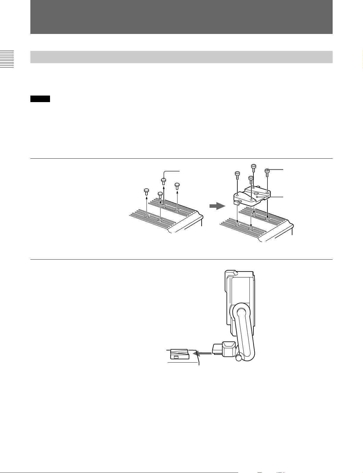
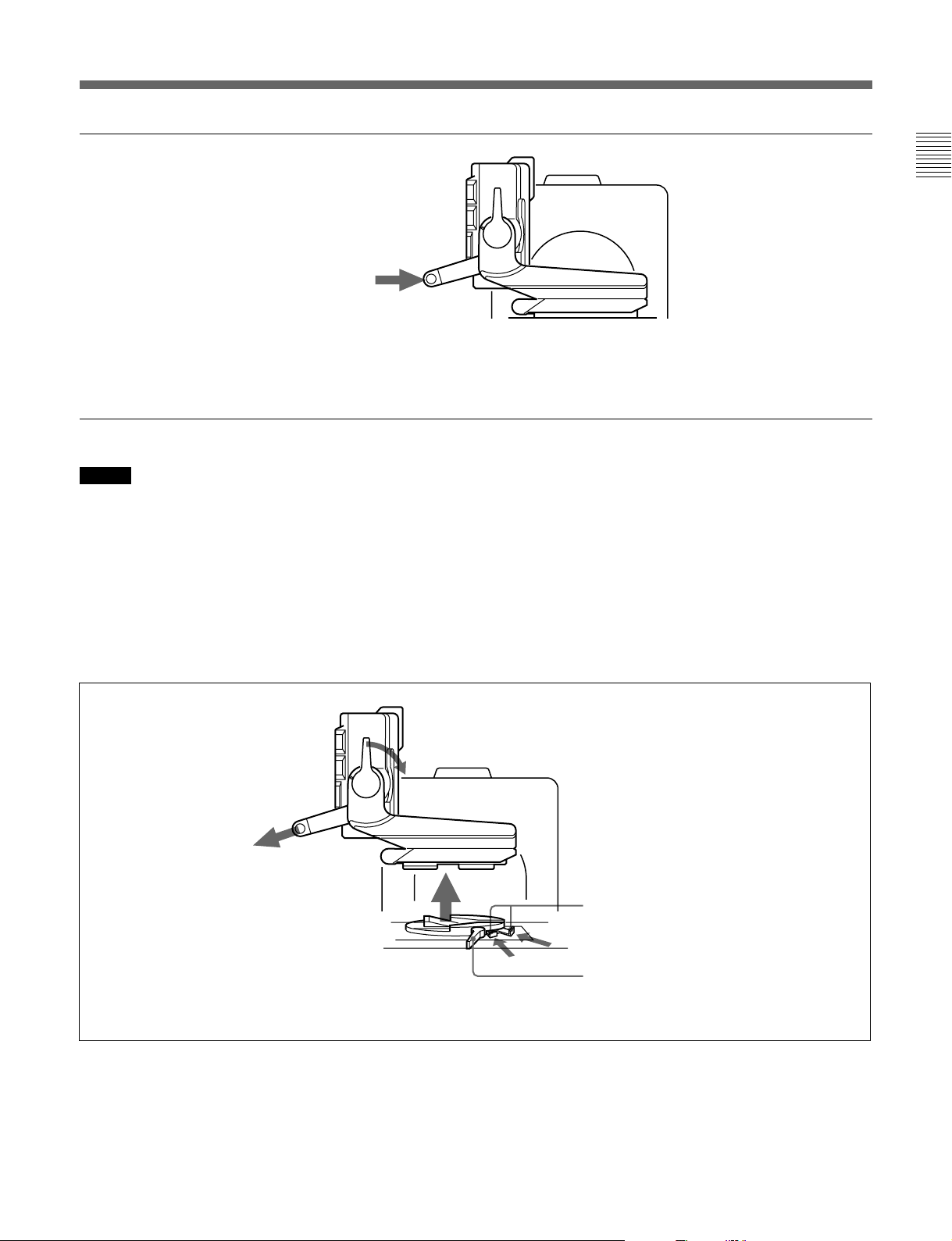
カメラに取り付ける
HDVF-C750W
カメ ラに Vウェ ッジシューアタ ッチメント(付属)を取り付け、 ア タッ
チメントに本機を取り付けます。
ご注意
・本機をカメラに取り付け/取り外しすると きには、かな らず本機を
標準位置(最高位置)にロックしてください。
・本機をカメラから取 り外すと きは、三脚のチルトロックを確 実に行
い、本機 を確実に持って取り 外してください。また、本機およびカ
メラの転倒・落下にご注意ください。
の場合
1 4 個のプラスチッ クキャッ プを外し、 L
レンチ(付属)と六角穴付きボルト(4
×12、4本付属)を使って、Vウェッ
ジシューアタ ッチメ ン ト(付属)をカメ
ラの上部に取り付ける。
◆ カメラに取り付けた後 、本機の位置を変える方法に ついては、「位置を
調節する」(10(J)ページ)の手順をご覧ください。
プラスチックキャップ
六角穴付きボルト
、付属
(4×12
ウェッジシュー
V
アタッチメント(付属
)
)
2 フリクシ ョ ン調節/ロ ックレバー を時
計回りの方向に回してロックする。
本機をVウェッ ジシューアタ ッチメ ント
にしっかりと差し込む。
カチッと音がして固定されます。
6(J)
Page 9
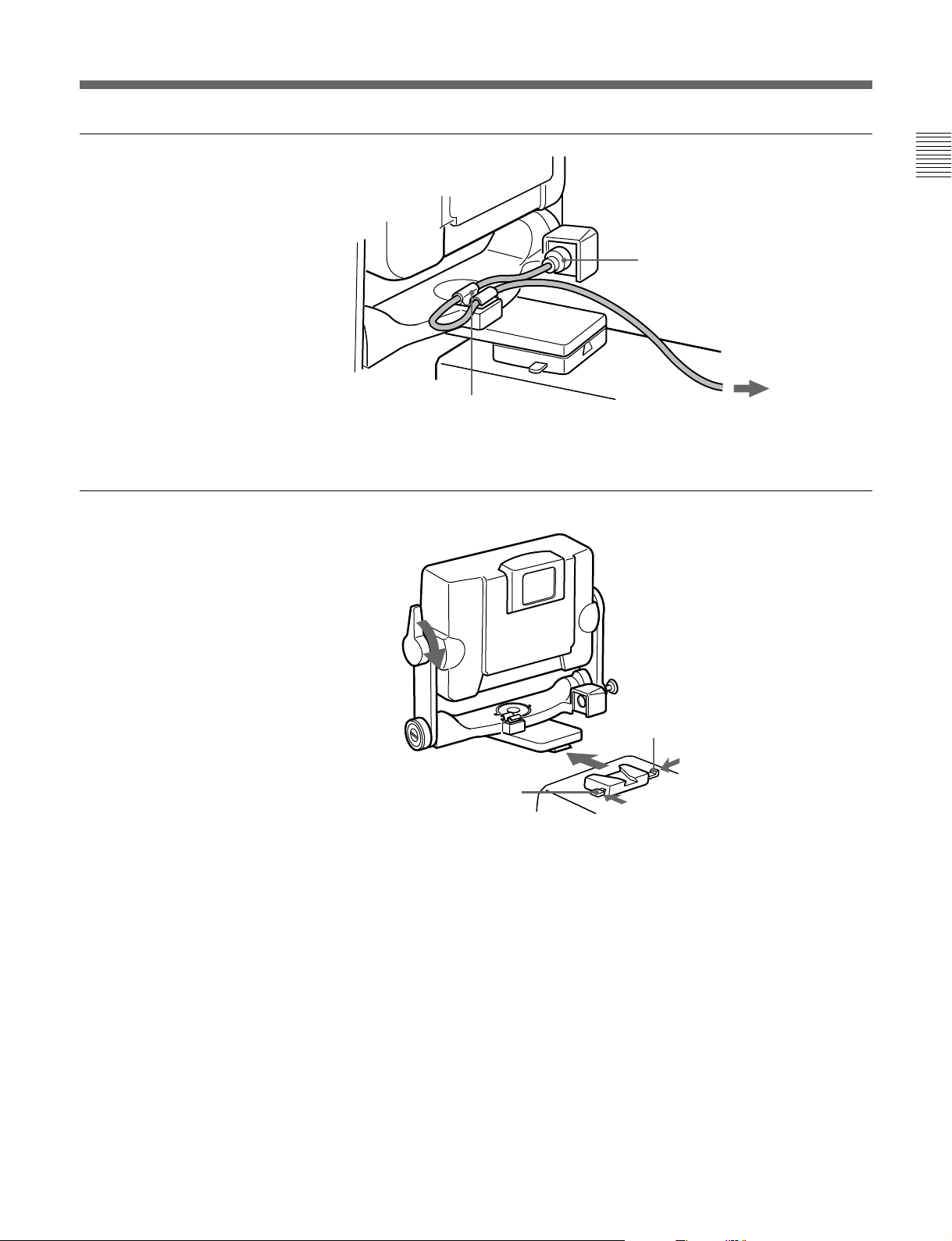
3 接続ケーブル(付属)を使用して 、
本機のカメラ端子とビデオカメラの
VF端子とを接続する。
接続ケーブルは、下図のようにクラン
パーで固定する。
カメラ端子
取り外すときは
フリクシ ョ ン調節/ロックレバーを時計回り
の方向に回してロックします。
レバーを引きながらボタンを押して取り外し
ます。
クランパー
レバー
ボタン
ビデオカメラの
端子へ
VF
7(J)
Page 10
カメラに取り付ける
カメラに取り付ける
HDVF-C700W
本機をカメ ラ上面のパンベース受け台(下図)に取り 付けます。
ご注意
・ビュー ファインダーを取り付ける前に、 カメ ラのパンベース受け台
のVF端子が、カメ ラのコントロールパネルを基準にして時計回り
に90 ゜の向きになっている ことを確認してください。
・本機をカメラから取 り外すと きは、三脚のチルトロックを確 実に行
い、本機 を確実に持って取り 外してください。また、本機およびカ
メラの転倒・落下にご注意ください。
の場合
パンベース
端子
VF
字型溝
V
ロック解除つまみ
溝
本機底面
突起部
1 フリクション調節/ロックレバーを時計
回りの方向に回し てロックす る。
マウ ントウェッジをV字型溝に、突起部
をパ ンベ ース受け台の左右の溝に合
わせて、本機をパンベース受け台に
乗せる。
マウントウェッジ
CAMERA
ビューファインダー取り付け機構
端子
突起部
パンベース受け台
パンニングロックレバー
ビューファインダー取り付け部
(カメラ上面)
マウントウェッジ
溝
カメラのコントロールパネル側
字型溝
V
パンベース受け台
8(J)
Page 11
2 本機の取っ手を持って、本機を押す。
カメラ端子が、VF端子に接続されま
す。
取り外すときは
ご注意
ビューフ ァインダーを取り外す前に、カメ ラのパンニングロック レ
バー を解除 し、ビュ ーファインダーをカメ ラのコントロールパネルを基
準にして時計回りに90゜回転させてください。 この位置でないと、
ビュー ファ インダーを取り外すことができません。
カメラのコントロールパネル側
フリクション調節/ロックレバーを時計回りの方向に回してロックし
ます。ロック解除つま み を押し込んだまま、本機の取っ手を持って
本機を引き上げ、取り外します。
カメラのコントロールパネル側
ロック解除つまみ
パンニングロックレバー
9(J)
Page 12

位置を調節する
ご注意
HDVF-C750W
本機をカメラに取り付けたままカメラを移動す るときは、本機を標準
位置(最高位置)まで引き上げ、フリクショ ン調節/ロッ クレバー を
カメ ラのレンズ 側に倒してロック してく ださい。 また、 リフトロック解
除ノブ1がLOCK側に固定されていることを確認してください。
高さ調節
の場合
(HDVF-C750W
のみ
)
1 リフトロック解除ノブ1をRELEASE側に止るまで回してロック
を解除する。
2 本機を確実に持ち ながら、リフトロック解除ノブ 2 を引き、本
機を標準位置(最高位置)、中間位置、または、最低位置
に移動する。
カチッと音がして固定されます。
調節後、リフトロック解除ノブ1をLOCK側に回して確実に固
定する。
HDVF-C700W
本機をカメラに取り付けたままカメ ラを移動すると きは、フリクション
調節 /ロック レバーをカメラのレンズ側 に倒してロックして ください。
ご注意
本機は標準位置(最高位置)、中間位置、最低位置のいずれかの
位置のみで固定が可能です。
の場合
リフトロック解除ノブ
標準位置(最高位置
2
リフトロック解除ノブ
2
1
1
90°
60°
)
中間位置
90°
90°
最低位置
60°
90°
10(J)
Page 13

チルティング操作
1 フリクショ ン調節/ロックレバーを回して、フリクショ ンを調節す
る。(下図はHDVF-C750W)
12
2 チルティング角度を調節する。(下図はHDVF-C750W)
調節範囲は次の通り。
HDVF-C750W:+90゜〜−90゜(高さ調節の位置により異なる。)
◆詳しくは、10(J)ページの図をご覧ください。
HDVF-C700W:+90゜〜−50゜
チルティン グ角度を調節した後は、フリクシ ョン調節/ロ ックレ
バー を カ メラのレンズ側に倒 してロックす る 。
パンニング操作(
本機を持って、本機を希望の角度に調節する。
◆ HDVF-C700Wにはパン機構がありません。
パン機構の 付い ているカメ ラに取り付けた状態で、カメラ側のパン機
構を利用 して角度を調節しま す。
操作方法については、カメラのオペレーションマニュアルをご覧くださ
い。
HDVF-C750W
のみ)
11(J)
Page 14

画面を調整する
BRIGHT
6
4
2
CONTRAST
6
4
2
PEAKING
MAX
OFF
108
0
108
0
1
2
3
1 BRIGHTつまみを回して、画面の明る さを調節する。
明るくするには、時計方向に回します。
2 CONTRASTつまみを回して、画面のコントラス トを調節する。
3 PEAKINGつまみを回して、ピーキングを補正する。
輪郭をはっきりとさせるには、時計方向に回します。
12(J)
Page 15

アクセサリーを取り付ける
フードを取り付ける
屋内フード (付属)の取 り 付けかた を説明します。
屋外フードVFH-770(別売り)の取り付けかたも同じです。
1 溝に引っかけて、 取り 付け る。
2 ネ ジを回 して固定する 。
溝
フー ドは上方向に30°向きを変えること ができ ます。
屋内フード
ネジ
13(J)
Page 16

アクセサリーを取り付ける
屋外フード(別売り
屋外フードが動きにくいと きや、逆に所定の位置に留まりにくいとき
は、コイ ンネ ジで調節します。右に回 すと動きが重くなり、 左へ回す
と軽くなります。
)
コインネジ
ナンバープレートを取り付ける
ナンバープレー ト(付属)の左右のつめを外部タリー ランプの溝に差
し込みます。
外部タリーランプ
ナンバープレート
1
14(J)
Page 17

仕様
一般
電源 DC10.5〜17.0V(カメラから供給)
消費電力 10W
使用温度 0゜C〜45゜C
保存温度 −20゜C〜60゜C
質量 HDVF-C750W:2.0kg(フード含まず)
HDVF-C700W:2.2kg(フード含まず)
外形寸法(単位:mm)
HDVF-C750W:
259
215
HDVF-C700W:
260
216
314
1080/50i/28.13kHz/ 50Hz
1080/59.94i/33.72kHz/59.94Hz
1080/60i/33.75kHz/ 60Hz
1035/59.94i/33.72kHz/59.94Hz
1035/60i/33.75kHz/60Hz
色温度 6500K
表示ランプ RTALLY/GTALLY/BATT/
入力信号
Pb,Pr:0.7Vp-p、同期なし、75Ω終端
Y :1.0Vp-p、同期あり、75Ω終端
接続端子
カメラ端子 HDVF-C750W:丸型20ピン
HDVF-C700W:D-sub25ピン
190
258
LCD
6型、カラー、TFT液晶
画像表示部 132×74mm(水平/垂直、アスペクト比
16:9)
タリー表示部 132×4(水平/垂直、上部および下部)
性能
輝度 300cd/m
解像度 500本以上
対応フォーマット
有効走査線数/フォーマット/水平走査線周波数/垂直走
査線周波数
1080/23.98PsF/26.97kHz/47.95Hz
1080/ 24PsF/27kHz/ 48Hz
1080/25PsF/28.13kHz/ 50Hz
1080/29.97PsF/33.72kHz/59.94Hz
1080/30PsF/33.75kHz/ 60Hz
2
付属品
屋内フード(1)
ナンバープレー ト(1)
オペ レー ションマニュアル(1)
以下はHDVF-C750Wのみ
Vウェッジシューアタ ッチメント(1)
Lレンチ(1)
六角穴付きボルト(4)
接続ケーブル(1)
別売り品
屋外フードVHF-770
関連製品
HDカラーカメラHDC-900/950
HDカムコーダーHDW-F900
大型レンズアダプターCA-905L+BKP-9057
本機の仕様および外観は、改良のため予告なく変更することがあ
りますが、ご了承ください。
15(J)
Page 18

Table of Contents
English
Overview............................................................................................... 2(E)
Notes...................................................................................................... 2(E)
Location and Function of Parts.......................................................... 3(E)
Attaching to the Camera..................................................................... 6(E)
In the case of the HDVF-C750W ....................................................6(E)
In the case of the HDVF-C700W ....................................................8(E)
Adjusting the Position ....................................................................... 10(E)
Adjusting the height (HDVF-C750W only)..................................10(E)
Tilting ............................................................................................11(E)
Panning (HDVF-C750W only) .....................................................11(E)
Adjusting the Screen ......................................................................... 12(E)
Attaching Accessories........................................................................ 13(E)
Attaching hoods.............................................................................13(E)
Attaching a number plate ..............................................................14(E)
Specifications...................................................................................... 15(E)
1(E)
Page 19

Overview
The HDVF-C750W/C700W HD Electronic
Viewfinder is a 6-type color viewfinder for use with a
Sony high-definition color camera.
This viewfinder has the following features:
Compact and lightweight
The viewfinder uses an LCD panel, making it more
compact in size and lighter in weight as compared with
a CRT viewfinder that has a display of the same size.
Multiscan
In addition to the 60i format, formats such as 24PsF
and 50i are supported for control signals from the
camera.
High resolution
The high-resolution LCD panel of the viewfinder
provides 500 or more lines of horizontal resolution.
Stable picture
Tally lamps
The viewfinder has red and green tally lamps which
light in response to tally signals.
Superior usability
The height of the HDVF-C750W can be set to one of
three positions. It can be tilted up to 90° upwards or
90° downwards, and can be panned up to 90° leftwards
or 90° rightwards.
The HDVF-C700W can be tilted up to 90° upwards or
50° downwards.
Drip-proof construction
The drip-proof design is able to withstand light rain,
making the viewfinder well suited to outdoor use.
Studio monitor hood, outdoor hood
The viewfinder can be fitted with a strong, easy-to-use
hood (supplied), or an outdoor hood with excellent
shading ability (option).
The LCD panel provides a stable image without
distortion, regardless of screen brightness.
Step-variable peaking
Step-variable peaking circuits provide a sharp image,
making it easy to focus the camera.
Notes
•The LCD panel of this unit is a product of highprecision technology. In rare cases, there may be one
or more dropout pixels or pixels (red, blue, green,
etc.) which are always on. This is not a malfunction
(99.99% or more effective pixels). The existence of
such pixels has no effect on the output of the camera.
Energy-saving design
The viewfinder will accept a wide range of power
supply voltage (from 10.5 to 17 volts) with low power
consumption (10 watts).
•When using the viewfinder at low temperature,
dynamic resolution drops just after turning the power
on.
•Use a blower to remove dust from the screen.
•Do not use a solvent such as thinner to clean the
screen.
2(E)
Page 20

Location and Function of Parts
The figure illustrates the HDVF-C750W.
The parts of the HDVF-C750W and the HDVF-C700W
have basically the same functions.
1 POWER switch
2 (attention) indicator
3 Red tally lamps
4 BRIGHT control
5 Friction adjustment/lock lever
6 CONTRAST control
7 PEAKING control
Front
Rear
8 BATT indicator
9 Green tally lamps
q; Lift-lock release knob 1
qa External tally lamp
qs External tally dimmer control
qd TALLY ON/OFF switch
qf Blanking marker ON/OFF switch
qg Tally dimmer switch
qh Lift-lock release knob 2
qj CAMERA connector
qk Clamper
ql Mounting wedge
3(E)
Page 21

Location and Function of Parts
1 POWER switch
Turns the power supply from the camera to the
viewfinder on and off.
(attention) indicator
2
This indicator lights when the camera detects certain
conditions. The particular conditions which cause the
indicator to light up are set up by the camera.
For information on how to set up and verify the conditions
under which the indicator will light, refer to the manual
for the camera being used.
3 Red tally lamps
Light up when the camera receives a red tally signal.
4 BRIGHT(brightness)control
1)
Adjusts the picture brightness.
5 Friction adjustment/lock lever
Adjusts the amount of friction in the tilting
mechanism. Also, locks the viewfinder into a desired
angle. The angle is locked when the lever is pushed
towards the camera lens. When the lever is pulled
towards the back of the camera, the tilting mechanism
can be adjusted.
6 CONTRAST control
1)
Adjusts the picture contrast.
The threshold battery voltage value to make this indicator
begin blinking is set by the camera. For details, refer to the
manual for the camera.
9 Green tally lamps
Light up when the camera receives a green tally signal.
q; Lift-lock release knob 1 (HDVF-C750W only)
Adjust the viewfinder height using lift-lock release
knob 2 qh together with this knob.
For operation instructions, see “Adjusting the height
(HDVF-C750W only)” on page 10(E).
qa External tally lamp
Lights up red in response to a red tally signal. Can be
used to display the camera number by attaching one of
the supplied number plates (0 through 9).
qs External tally dimmer control
Adjusts the brightness of the external tally lamp. Use a
screwdriver to turn the control counterclockwise to
increase the brightness, or clockwise to dim the lamp.
qd TALLY ON/OFF switch
Controls the external tally lamp qa. When set to ON,
the external tally lamp will operate.
When set to OFF, the lamp will not operate (will not
light in response to a tally signal).
7 PEAKING control
1)
Sharpens the edges in the picture. Turning the control
qf Blanking marker ON/OFF switch
Turns the display of the blanking marker on and off.
clockwise increases the sharpness. The peaking can be
adjusted from off to 16 dB.
qg Tally dimmer switch
Adjusts the brightness of the red tally lamps 3, the
8 BATT (battery) indicator
This indicator blinks when the voltage output of the
camera battery drops. When the battery reaches a point
green tally lamps 9, the
and the BATT (battery) indicator 8 on the front
panel.
(attention) indicator 2,
that it may no longer be used, the indicator will light
up.
To prevent camera shut down due to the battery
running down, change the battery as soon as possible
after this indicator begins blinking.
........................................................................................................................................................................................
1) These controls have no effect on the camera’s video
output signals.
4(E)
Page 22

qh Lift-lock release knob 2 (HDVF-C750W only)
Adjust the viewfinder height using lift-lock release
knob 1 q; together with this knob.
For operation instructions, see “Adjusting the height
(HDVF-C750W only)” on page 10(E).
qj CAMERA connector (HDVF-C750W : Round
type 20-pin, HDVF-C700W : D-sub 25-pin)
HDVF-C750W: Connect to the camera’s viewfinder
connector using the supplied connecting cable.
HDVF-C700W: The CAMERA connector is on the
bottom of the viewfinder. Connect to the camera’s
viewfinder connector.
qk Clamper (HDVF-C750W only)
Clamps the supplied connecting cable.
ql Mounting wedge
To attach the viewfinder to a camera, the mounting
wedge is inserted into the V-shaped groove on the top
of the camera.
5(E)
Page 23

Attaching to the Camera
In the case of the HDVF-C750W
Attach the V-shaped shoe attachment to the top of the
camera, then attach the viewfinder to the V-shaped
shoe attachment.
Notes
•Before attaching the viewfinder to or removing it
from a camera, always be sure to lock the viewfinder
in the standard (top) position.
•Before removing the viewfinder from the camera, be
sure to lock the tilt lock of the tripod. Grasp the
viewfinder firmly when removing, and be careful not
to drop it or the camera.
1 Remove the four plastic caps,
then use the supplied
hexagonal key and the
hexagonal socket head screws
(4×12, four screws supplied)
to attach the supplied V-shaped
shoe attachment to the top of
the camera.
For more information about adjusting the viewfinder
position, see “Adjusting the Position” on page 10 (E).
Plastic cap
Hexagonal socket head
screw
V-shaped shoe
attachment
2 Turn the friction adjustment/
lock lever clockwise to lock
the viewfinder. Mount the
viewfinder firmly in the Vshaped shoe attachment.
There is an audible click when
the viewfinder snaps into the
attachment.
6(E)
Page 24

3 Connect the viewfinder’s
camera connector to the
camera’s viewfinder connector
using the supplied connecting
cable.
Clamp the connecting cable in
the clamper.
Removing the viewfinder
Turn the friction adjustment/lock
lever clockwise to lock the
viewfinder. Remove the
viewfinder from the attachment by
pushing the button while pulling
the lever.
Clamper
CAMERA connector
To the camera’s
viewfinder connector
Lever
Button
7(E)
Page 25

Attaching to the Camera
In the case of the HDVF-C700W
The viewfinder is attached to the panning base
mounting plate (see the figure below) on the top of the
camera.
Panning base
Mounting wedge
CAMERA connector
Bottom of viewfinder
Protrusions
Notes
•Before attaching the viewfinder to the camera, check
to be sure that the VF connector on the camera’s
panning base mounting plate faces in the direction
90° clockwise to the camera’s control panel.
•Before removing the viewfinder from the camera, be
sure to lock the tilt lock of the tripod. Grasp the
viewfinder firmly when removing, and be careful not
to drop it or the camera.
VF connector
V-shaped groove
Lock release tabs
Depressions
Panning base mounting plate
Panning lock lever
Viewfinder attachment shoe (top of camera)
1 Turn the friction adjustment/
lock lever clockwise to lock
the viewfinder. Aligning the
mounting wedge with the Vshaped groove, and the
protrusions on the viewfinder
with the depressions on the left
and right of the panning base
mounting plate, set the
viewfinder on the panning base
mounting plate.
Viewfinder attachment mechanism
Protrusions
Mounting wedge
V-shaped groove
Panning base
Depressions
Camera’s control panel side
mounting plate
8(E)
Page 26

2 Holding on to the handle, push
the viewfinder forwards.
The CAMERA connector will
mate with the camera’s VF
connector.
Removing the viewfinder
Notes
Before detaching the viewfinder from the camera,
release the camera’s panning lock lever and turn the
viewfinder in the direction 90° clockwise to the
camera’s control panel. You cannot detach the
viewfinder from the camera unless it is in this position.
Turn the friction adjustment/lock lever clockwise to
lock the viewfinder.
While pushing in the lock release tabs, grasp the
viewfinder handle and lift the viewfinder to remove it
from the camera.
Camera’s control panel side
Camera’s control panel side
Lock release tabs
Panning lock lever
9(E)
Page 27

Adjusting the Position
Notes
In the case of the HDVF-C750W
Before moving the camera with the viewfinder
attached, always pull the viewfinder up to the standard
(top) position and push the friction adjustment/lock
lever towards the camera lens to lock the viewfinder.
Also, check to be sure that lift-lock release knob 1 is
locked in the “LOCK” position.
Adjusting the height (HDVF-C750W only)
1 Turn lift-lock release knob 1 in the direction of
“RELEASE” until it will not go further, to unlock
the lifting mechanism.
2 Holding the viewfinder firmly, pull lift-lock
release knob 2 and move the viewfinder to the
standard (top) position, middle position, or low
position.
There is an audible click when the viewfinder
snaps into the position.
In the case of the HDVF-C700W
Before moving the camera with the viewfinder
attached, always push the friction adjustment/lock
lever towards the camera lens to lock the viewfinder.
After adjusting the height, be sure to always turn
lift-lock release knob 1 to the “LOCK” position to
lock the lifting mechanism.
Note
The viewfinder snaps into place at the standard (top)
position, middle position, or low position.
Lift-lock release knob 1
Standard (top) position
90°
2
Lift-lock release knob 2
1
90°
60°
60°
90°
Middle position Low position
90°
10(E)
Page 28

Tilting
1 Turn the friction adjustment/lock lever to set the
desired tilt friction. (The figure below illustrates
the HDVF-C750W.)
12
2 Adjust the tilt angle. (The figure below illustrates
the HDVF-C750W.)
Tilting ranges are as follows.
HDVF-C750W: +90° to –90°
(Depending on the adjusted
height of the viewfinder)
For details, see the figure on page
10(E).
HDVF-C700W: +90° to –50°
After setting the viewfinder to the desired angle,
push the friction adjustment/lock lever towards the
camera lens to lock the viewfinder in position.
Panning (HDVF-C750W only)
Holding the viewfinder, adjust the desired panning
angle.
The HDVF-C700W does not have a panning mechanism.
When it is attached to a camera that has a panning
mechanism, use the camera’s panning mechanism to adjust
the angle.
For operation instructions, refer to the operation manual of
the camera.
11(E)
Page 29

Adjusting the Screen
BRIGHT
6
4
2
CONTRAST
6
4
2
PEAKING
MAX
OFF
108
0
108
0
1
2
3
1 Turn the BRIGHT control to adjust the brightness
of the screen. Turning the control clockwise
makes the picture brighter.
2 Turn the CONTRAST control to adjust the screen
contrast.
3 Turn the PEAKING control to adjust the peaking.
Turn the control clockwise to make edges in the
image sharper.
12(E)
Page 30

Attaching Accessories
Attaching hoods
This section describes how to attach the supplied
monitor hood. The VFH-770 Outdoor Hood (sold
separately) is attached in the same manner.
1 Hook the hood on the
projection over the screen.
2 Tighten the screw to fix the
hood in place.
Projection
Screw
The hood direction can be adjusted up by 30º.
Monitor hood
13(E)
Page 31

Attaching Accessories
Outdoor hood (sold separately)
When the outdoor hood is difficult to move, or when it
won’t stay in a set position, adjust the tilt friction using
the screw. Turning the screw clockwise will tighten
the joint, and turning it counterclockwise will loosen it.
Screw
Attaching a number plate
Insert the tabs on the sides of the required number
plate (supplied) into the slots on the sides of the
external tally lamp.
External tally lamp
Number plate
1
14(E)
Page 32

Specifications
General
Power supply DC10.5 to 17.0V (supplied by the
camera)
Power consumption
10W
Operating temperature
0°C to 45°C (32°F to 113°F)
Storage temperature
–20°C to 60°C (–4°F to 140°F)
Mass HDVF-C750W: 2.0kg(4.4 lb) not
including hood
HDVF-C700W: 2.2kg(4.9 lb) not
including hood
External dimensions:
HDVF-C750W:
216mm (8 5/8 in)
216
215mm
215
(8 1/2 in)
259mm (10 1/4 in)
259
Performance
Brightness 300cd/m
Resolution 500 or more lines
Supported formats
Effective scanning lines / Format / Horizontal
scanning frequency / Vertical scanning frequency
1080/ 23.98PsF/ 26.97kHz/ 47.95Hz
1080/ 24PsF/ 27kHz/ 48Hz
1080/ 25PsF/ 28.13kHz/ 50Hz
1080/ 29.97PsF/ 33.72kHz/ 59.94Hz
1080/ 30PsF/ 33.75kHz/ 60Hz
1080/ 50i/ 28.13kHz/ 50Hz
1080/ 59.94i/ 33.72kHz/ 59.94Hz
1080/ 60i/ 33.75kHz/ 60Hz
1035/ 59.94i/ 33.72kHz/ 59.94Hz
1035/ 60i/ 33.75kHz/ 60Hz
Color temperature 6500K
Indicators R TALLY/G TALLY/BATT/
2
Input signals
HDVF-C700W:
260mm (10 1/4 in)
260
190mm
(7 1/2 in)
190
LCD
6-type color TFT screen
Image display area dimensions
132 × 74mm (5
aspect ratio)
Tally lamps display area dimensions
132 × 4mm (5
upper and the lower part)
314mm (12 3/8 in)
314
258mm (10 1/4 in)
258
1
/4 × 3 in) (16:9
1
/4 ×3/16 in, the
Pb,Pr: 0.7Vp-p, asynchronous, 75-Ω terminated
Y : 1.0Vp-p, synchronous, 75-Ω terminated
Connectors
CAMERA connector
HDVF-C750W: Round type 20-pin
HDVF-C700W: D-sub 25-pin
Supplied accessories
Monitor hood (1)
Number plate (1)
Operation manual (1)
The followings are supplied with the HDVF-C750W
only:
V-shaped shoe attachment (1)
Hexagonal key (1)
Hexagonal socket head screws (4)
Connecting cable (1)
Optional accessories
VHF-770 Outdoor Hood
15(E)
Page 33

Specifications
Related accessories
HDC-900/950 HD Color Video Camera
HDW-F900 HD Camcorder
CA-905L+BKP-9057 Large Lens Adaptor
Designs and specifications are subject to change
without notice.
16(E)
Page 34

The material contained in this manual consists of
information that is the property of Sony Corporation and is
intended solely for use by the purchasers of the equipment
described in this manual.
Sony Corporation expressly prohibits the duplication of any
portion of this manual or the use thereof for any purpose
other than the operation or maintenance of the equipment
described in this manual without the express written
permission of Sony Corporation.
Le matériel contenu dans ce manuel consiste en
informations qui sont la propriété de Sony Corporation et
sont destinées exclusivement à l’usage des acquéreurs de
l’équipement décrit dans ce manuel.
Sony Corporation interdit formellement la copie de quelque
partie que ce soit de ce manuel ou son emploi pour tout
autre but que des opérations ou entretiens de l’équipement
à moins d’une permission écrite de Sony Corporation.
Das in dieser Anleitung enthaltene Material besteht aus
Informationen, die Eigentum der Sony Corporation sind,
und ausschließlich zum Gebrauch durch den Käufer der in
dieser Anleitung beschriebenen Ausrüstung bestimmt sind.
Die Sony Corporation untersagt ausdrücklich die
Vervielfältigung jeglicher Teile dieser Anleitung oder den
Gebrauch derselben für irgendeinen anderen Zweck als die
Bedienung oder Wartung der in dieser Anleitung
beschriebenen Ausrüstung ohne ausdrückliche schriftliche
Erlaubnis der Sony Corporation.
Page 35

HDVF-C750W
HDVF-C700W
和, 英
(SY,
3-204-412-01(1)
)
Sony Corporation
Communication System Solutions Network Company
Printed in Japan
2000.02.13
2000
 Loading...